US7751694B2 - Three-dimensional endoscope imaging and display system - Google Patents
Three-dimensional endoscope imaging and display systemDownload PDFInfo
- Publication number
- US7751694B2 US7751694B2US11/314,408US31440805AUS7751694B2US 7751694 B2US7751694 B2US 7751694B2US 31440805 AUS31440805 AUS 31440805AUS 7751694 B2US7751694 B2US 7751694B2
- Authority
- US
- United States
- Prior art keywords
- dimensional
- focal length
- image
- endoscope system
- variable focal
- Prior art date
- Legal status (The legal status is an assumption and is not a legal conclusion. Google has not performed a legal analysis and makes no representation as to the accuracy of the status listed.)
- Active, expires
Links
- 238000003384imaging methodMethods0.000titleclaimsabstractdescription57
- 230000003287optical effectEffects0.000claimsdescription33
- 238000000034methodMethods0.000claimsdescription22
- 230000008859changeEffects0.000claimsdescription21
- 238000012545processingMethods0.000claimsdescription15
- 230000002085persistent effectEffects0.000claimsdescription8
- 230000004075alterationEffects0.000claimsdescription5
- 230000008569processEffects0.000claimsdescription5
- 238000013501data transformationMethods0.000claimsdescription4
- 230000001360synchronised effectEffects0.000claimsdescription3
- 230000003044adaptive effectEffects0.000claimsdescription2
- 238000010586diagramMethods0.000description13
- 230000004438eyesightEffects0.000description7
- 230000008901benefitEffects0.000description6
- 238000003745diagnosisMethods0.000description3
- 238000000605extractionMethods0.000description3
- 238000007689inspectionMethods0.000description3
- 238000010276constructionMethods0.000description2
- 239000000284extractSubstances0.000description2
- 208000014674injuryDiseases0.000description2
- 239000013307optical fiberSubstances0.000description2
- 230000004044responseEffects0.000description2
- 230000008733traumaEffects0.000description2
- 230000004308accommodationEffects0.000description1
- 208000003464asthenopiaDiseases0.000description1
- 238000012937correctionMethods0.000description1
- 230000007547defectEffects0.000description1
- 230000000593degrading effectEffects0.000description1
- 238000013461designMethods0.000description1
- 238000006073displacement reactionMethods0.000description1
- 230000000694effectsEffects0.000description1
- 239000000835fiberSubstances0.000description1
- 230000003993interactionEffects0.000description1
- 230000003902lesionEffects0.000description1
- 230000007246mechanismEffects0.000description1
- 239000000203mixtureSubstances0.000description1
- 230000002688persistenceEffects0.000description1
- 230000002035prolonged effectEffects0.000description1
- 238000002310reflectometryMethods0.000description1
- 238000013519translationMethods0.000description1
Images


Classifications
- G—PHYSICS
- G03—PHOTOGRAPHY; CINEMATOGRAPHY; ANALOGOUS TECHNIQUES USING WAVES OTHER THAN OPTICAL WAVES; ELECTROGRAPHY; HOLOGRAPHY
- G03B—APPARATUS OR ARRANGEMENTS FOR TAKING PHOTOGRAPHS OR FOR PROJECTING OR VIEWING THEM; APPARATUS OR ARRANGEMENTS EMPLOYING ANALOGOUS TECHNIQUES USING WAVES OTHER THAN OPTICAL WAVES; ACCESSORIES THEREFOR
- G03B35/00—Stereoscopic photography
- G03B35/18—Stereoscopic photography by simultaneous viewing
- A—HUMAN NECESSITIES
- A61—MEDICAL OR VETERINARY SCIENCE; HYGIENE
- A61B—DIAGNOSIS; SURGERY; IDENTIFICATION
- A61B1/00—Instruments for performing medical examinations of the interior of cavities or tubes of the body by visual or photographical inspection, e.g. endoscopes; Illuminating arrangements therefor
- A61B1/00002—Operational features of endoscopes
- A61B1/00043—Operational features of endoscopes provided with output arrangements
- A61B1/00045—Display arrangement
- A61B1/00048—Constructional features of the display
- A—HUMAN NECESSITIES
- A61—MEDICAL OR VETERINARY SCIENCE; HYGIENE
- A61B—DIAGNOSIS; SURGERY; IDENTIFICATION
- A61B6/00—Apparatus or devices for radiation diagnosis; Apparatus or devices for radiation diagnosis combined with radiation therapy equipment
- A61B6/46—Arrangements for interfacing with the operator or the patient
- A61B6/461—Displaying means of special interest
- A61B6/466—Displaying means of special interest adapted to display 3D data
- G—PHYSICS
- G02—OPTICS
- G02B—OPTICAL ELEMENTS, SYSTEMS OR APPARATUS
- G02B26/00—Optical devices or arrangements for the control of light using movable or deformable optical elements
- G02B26/08—Optical devices or arrangements for the control of light using movable or deformable optical elements for controlling the direction of light
- G02B26/0816—Optical devices or arrangements for the control of light using movable or deformable optical elements for controlling the direction of light by means of one or more reflecting elements
- G02B26/0833—Optical devices or arrangements for the control of light using movable or deformable optical elements for controlling the direction of light by means of one or more reflecting elements the reflecting element being a micromechanical device, e.g. a MEMS mirror, DMD
- G—PHYSICS
- G02—OPTICS
- G02B—OPTICAL ELEMENTS, SYSTEMS OR APPARATUS
- G02B30/00—Optical systems or apparatus for producing three-dimensional [3D] effects, e.g. stereoscopic images
- G02B30/50—Optical systems or apparatus for producing three-dimensional [3D] effects, e.g. stereoscopic images the image being built up from image elements distributed over a 3D volume, e.g. voxels
- G02B30/52—Optical systems or apparatus for producing three-dimensional [3D] effects, e.g. stereoscopic images the image being built up from image elements distributed over a 3D volume, e.g. voxels the 3D volume being constructed from a stack or sequence of 2D planes, e.g. depth sampling systems
- G—PHYSICS
- G03—PHOTOGRAPHY; CINEMATOGRAPHY; ANALOGOUS TECHNIQUES USING WAVES OTHER THAN OPTICAL WAVES; ELECTROGRAPHY; HOLOGRAPHY
- G03B—APPARATUS OR ARRANGEMENTS FOR TAKING PHOTOGRAPHS OR FOR PROJECTING OR VIEWING THEM; APPARATUS OR ARRANGEMENTS EMPLOYING ANALOGOUS TECHNIQUES USING WAVES OTHER THAN OPTICAL WAVES; ACCESSORIES THEREFOR
- G03B21/00—Projectors or projection-type viewers; Accessories therefor
- G03B21/14—Details
- G03B21/28—Reflectors in projection beam
- H—ELECTRICITY
- H04—ELECTRIC COMMUNICATION TECHNIQUE
- H04N—PICTORIAL COMMUNICATION, e.g. TELEVISION
- H04N13/00—Stereoscopic video systems; Multi-view video systems; Details thereof
- H04N13/20—Image signal generators
- H04N13/204—Image signal generators using stereoscopic image cameras
- H—ELECTRICITY
- H04—ELECTRIC COMMUNICATION TECHNIQUE
- H04N—PICTORIAL COMMUNICATION, e.g. TELEVISION
- H04N13/00—Stereoscopic video systems; Multi-view video systems; Details thereof
- H04N13/30—Image reproducers
- H04N13/302—Image reproducers for viewing without the aid of special glasses, i.e. using autostereoscopic displays
- H04N13/322—Image reproducers for viewing without the aid of special glasses, i.e. using autostereoscopic displays using varifocal lenses or mirrors
- H—ELECTRICITY
- H04—ELECTRIC COMMUNICATION TECHNIQUE
- H04N—PICTORIAL COMMUNICATION, e.g. TELEVISION
- H04N13/00—Stereoscopic video systems; Multi-view video systems; Details thereof
- H04N13/30—Image reproducers
- H04N13/388—Volumetric displays, i.e. systems where the image is built up from picture elements distributed through a volume
- H04N13/395—Volumetric displays, i.e. systems where the image is built up from picture elements distributed through a volume with depth sampling, i.e. the volume being constructed from a stack or sequence of 2D image planes
Definitions
- the present inventionrelates to endoscope systems, and in particular, a three-dimensional endoscope system comprising a real-time three-dimensional imaging device and a three-dimensional display device.
- An endoscopeis a minimal invasive imaging instrument having a rigid or flexible long narrow tube shape, allowing viewing an internal structure of a body through a natural opening or a small incision for clinical inspection and treatment.
- endoscopescomprise the lens system, a light and image delivery system such as relay lens or optical fibers, an imaging system, various channels for treatment tool passage, and a display system.
- Endoscopic proceduresrequire precise hand-eye coordination and minute manipulation, which can be hardly accomplished by monocular vision.
- Three-dimensional visionprovides more informative and intuitive observation of scene and precise interaction with environment than monocular vision does. Thus, it has become an indispensable element for the endoscope system.
- Three-dimensional visioncan be accommodated by binocular parallax, motion parallax, confocal scanning, structured light depth extraction techniques, and the like.
- U.S. Pat. No. 3,520,587 to Tasakidiscloses a stereoscopic endoscope having two objective lens systems with two fiber optic image delivery systems to provide a pair of stereoscopic images.
- U.S. Pat. No. 5,751,341 to Chaleki and U.S. Pat. No. 5,673,147 to McKinleyalso disclose systems and methods to provide a pair of stereoscopic images for endoscopes.
- a binocular vision systemcan cause eye-strain and fatigue for prolonged uses, and requires special eye-wear to see three-dimensional images.
- U.S. Pat. No. 6,798,570 to Greenbergdiscloses a three-dimensional imaging and reconstruction system with a single camera system using motion parallax.
- the camera systemmust be continuously moving to generate three-dimensional effect, which can make inspection and treatment procedures complicated and cause trauma to a patient.
- U.S. Pat. No. 6,949,069 to Farkasdiscloses a three dimensional confocal system in which a point of interest is illuminated by a light source using pinhole apertures.
- the confocal systemcan provide a high resolution three-dimensional image with a single camera system, but most of illuminating light is wasted and causes noise problem.
- U.S. Pat. No. 6,749,346 to Dickensheets and U.S. Pat. No. 6,563,105 to Seibeluse a single optical fiber to scan and collect reflected light, but point by point scanning can lead to a slow image refresh rate.
- U.S. Pat. No. 6,503,195 to Kellerdiscloses a structured light depth extraction system in which a projector projects a structured light pattern such as grids in the visible or invisible form onto an object, and then an image processor calculates the depth information based on the reflected light pattern.
- a projectorprojects a structured light pattern such as grids in the visible or invisible form onto an object
- an image processorcalculates the depth information based on the reflected light pattern.
- image qualitycan be degraded while using invisible light requires an additional sensor system.
- performance of the structured light depth extraction systemdepends on the reflectivity of the object.
- a wide field of viewis useful for viewing an overall internal structure and spotting an area of interest, but it may not provide enough information for diagnosis or treatment because the image produced by the wide field of view tends to suffer from huge distortion and low resolution.
- a narrow field of viewproduces a better quality and higher resolution image, and facilitates diagnosis and treatment.
- a desirable endoscope systemmust provide both wide and narrow fields of view.
- variable magnification(or a variable field of view) can be accomplished by changing relative locations of lenses in multiple lens system like a zoom lens system.
- itrequires complicated macroscopic servo mechanism and yields a slow response time.
- variable optical axis imaging systemwithout macroscopic reposition or rotation of the endoscope body can benefit a patient by reducing unnecessary contact between lesion and the instrument.
- the minimal invasive nature of endoscopic proceduresrequires the tube with a small diameter to reduce the size of incision and patient's trauma, sharp three-dimensional video images since a clinician can not see an object directly, a wide field of view for surveying the area of interest, a narrow field of view with high resolution images for inspection and treatment, and a variable optical axis to view the surrounding area without macroscopic movements of an endoscope body or parts thereof.
- the present inventionprovides a three-dimensional endoscope system comprising a three-dimensional imaging device and a three-dimensional display device using a variable focal length micromirror array lens (MMAL).
- MMALvariable focal length micromirror array lens
- An objective of the inventionis to provide a three-dimensional imaging device that generates in-focus depthwise images with depth information or an all-in-focus image with depth information of each pixel.
- the three-dimensional imaging devicecomprises at least one camera system having a lens system including at least one variable focal length MMAL, an objective lens, and auxiliary lenses, an imaging unit, an image processing unit, and a light delivery system.
- a lens systemincluding at least one variable focal length MMAL, an objective lens, and auxiliary lenses, an imaging unit, an image processing unit, and a light delivery system.
- the variable focal length MMALcomprises a plurality of micromirrors.
- the following U.S. patents and applicationsdescribe the MMAL: U.S. Pat. No. 6,934,072 to Kim , U.S. Pat. No. 6,934,073 to Kim , U.S. Pat. No. 6,970,284 to Kim , U.S. patent application Ser. No. 10/855,715 filed May 27, 2004, U.S. patent application Ser. No. 10/857,714 filed May 28, 2004, U.S. patent application Ser. No. 10/857,280 filed May 28, 2004, U.S. patent application Ser. No. 10/893,039 filed Jul. 16, 2004, U.S. patent application Ser. No. 10/983,353 filed Nov. 8, 2004, all of which are hereby incorporated by reference.
- variable focal length MMALis suitable for the three-dimensional imaging and display device of the present invention since it has a fast focusing speed and a large range of focal length, and since it can be made to have a small or large aperture.
- the imaging unitincludes one or more two-dimensional image sensors taking two-dimensional images at different focal planes.
- the detail for three-dimensional imaging using the variable focal length MMALcan be found in U.S. patent application Ser. No. 10/822,414 filed Apr. 12, 2004, U.S. patent application Ser. No. 10/979,624 filed Nov. 2, 2004, and U.S. patent application Ser. No. 11/208,115 filed Aug. 19, 2005.
- the image sensortakes two-dimensional images of an object or scene with one or more focal planes that are shifted by changing the focal length of the variable focal length MMAL.
- the image processing unitextracts substantially in-focus pixels or areas from each two-dimensional image to generate a corresponding in-focus depthwise image. Based on the known focal length of the two-dimensional image, depth information of the corresponding in-focus depthwise image can be obtained. Each in-focus depthwise image represents a portion of the object having the same image depth.
- the focal length of the variable focal length MMALcan progressively increase or decrease, or varies in a selected order within a focal length variation range of the variable focal length MMAL such that any portion of the object or scene is imaged substantially in-focus at least once.
- a set of in-focus depthwise images taken at different focal lengths with a fast imaging raterepresents the object or scene at a given moment.
- the objectcan remain still or be moving. For the case that the object is moving, the movement of the object can be ignored when the imaging rate is fast enough.
- the number of in-focus depthwise images representing the object at a given momentdepends on the depth resolution requirement, and the refresh rate of the two-dimensional display and the focusing speed of the variable focal length MMAL, and may increase for a better image quality.
- a set of depthwise images with depth information or an all-in-focus image with depth informationcan be displayed by various conventional three-dimensional display devices through geometric data transformation.
- the present inventionincludes a three-dimensional display device, which displays these images without data transformation, as explained below.
- variable magnificationa variable field of view
- the variable focal length MMAL of the present inventionhas a large range of focal length variation, which can offer a variable field of view; a shorter focal length for a wider field of view and a longer focal length for a narrow field of view.
- the field of viewis changed without macroscopic movements of the lens system because each micromirror of the variable focal length MMAL is adjusted for varying the focal length and actuated by the electrostatic force and/or electromagnetic force.
- Still another objective of the inventionis to provide an imaging device having a variable optical axis without macroscopic movements of an endoscope body or parts thereof in order to center the object of interest in the image plane.
- the optical axis of the variable focal length MMALcan be adjusted in a limited range by controlling each micromirror of the MMAL independently without macroscopic movements of the endoscope body or parts thereof.
- Still another objective of the inventionis to provide an imaging device that can compensate the aberration caused by optical effects due to the medium between the object and its image or defects of a lens system that leads its image to deviate from the rules of paraxial imagery, by controlling each micromirror independently.
- the present imaging deviceproduces a sharp image through entire area without blurring or vignetting.
- Still another objective of the inventionis to provide a small and compact imaging device in order to have an endoscope body with a small diameter, which allows a minimal invasive endoscopic procedure.
- the present inventioncan determine three-dimensional information using only a single camera system, and this renders a simpler camera calibration and a more compact imaging device.
- the MMALcan be made to have a small aperture and the magnification and optical axis can be adjusted without macroscopic movements of the lens system, the endoscope imaging system of the present invention can be made small and compact.
- the three-dimensional endoscope imaging device of the present inventionhas the following advantages: (1) the device provides a set of in-focus depthwise images with depth information and/or an all-in-focus image with depth information representing an object at a given moment; (2) the device has a large range of depth; (3) the device has a high optical efficiency; (4) the device corrects aberration; (5) the device can have high depth resolution; (6) the device has a variable field of view; (7) the device has a variable optical axis; (8) the cost is inexpensive because the MMAL is inexpensive; (9) the device has a very simple structure because there is no macroscopic mechanical displacement or deformation of the MMAL; (10) the device is small and compact; (11) the device requires small power consumption when the MMAL is actuated by electrostatic force.
- Other objectives of the inventionare to provide a three-dimensional display device that has a simple construction and realistic image representation, to provide a three-dimensional display device and method that utilize a set of depthwise images, to provide a three-dimensional display device that can display a large range of image depth, to provide a three-dimensional display device that comprises two-dimensional/three-dimensional compatibility, and to provide a three-dimensional display device that has a large size variation.
- Three-dimensional display using the MMALis proposed in the U.S. patent application Ser. No. 10/778,281 filed Feb. 13, 2004 and U.S. patent application Ser. No. 10/979,624 filed Nov. 2, 2004.
- the three-dimensional image display device of the present inventionhas the following advantages: (1) since the three-dimensional display device actually generates three-dimensional images in the space, the device does not suffer from the disadvantage of prior art device using parallax including imaging difficulties due to considerations for arbitrary distribution of the viewer's position, and binocular disparity due to deviations in the distance between the two eyes, vergence, accommodation, watching by more than one viewers, and the relative position change of the three-dimensional image due to viewer's movement; (2) the cost for providing three-dimensional image data is inexpensive since the data needs only depth information in addition to two-dimensional image information, and thus there is no significant increase in data amount; and (3) the device can be easily converted to a two-dimensional display and vice versa.
- FIG. 1is a schematic illustration of an endoscope system with a variable optical axis
- FIG. 2is a schematic illustration of an endoscope system with a variable optical axis and a variable magnification (a variable field of view);
- FIG. 3is a schematic diagram showing how in-focus depthwise images are obtained from two-dimensional images with different focal planes
- FIG. 4is a schematic representation for optical axis changes in the MMAL
- FIGS. 5A-5Dare schematic diagrams showing how the depth of an image is changed as the focal length of a lens is changed
- FIG. 6is a schematic diagram showing a three-dimensional display device of the present invention.
- FIGS. 7A-7Care schematic diagrams showing how a two-dimensional display and a variable focal length MMAL displays three-dimensional images
- FIG. 8Ais a schematic diagram showing how a refractive Fresnel lens replaces an ordinary single-bodied lens
- FIG. 8Bis a schematic diagram showing how a reflective Fresnel lens replaces an ordinary single-bodied mirror
- FIG. 9Ais a schematic plan view showing a variable focal length MMAL that is made of many micromirrors
- FIG. 9Bis an enlarged detail plan view of the micromirrors
- FIG. 10is a schematic diagram showing a beam splitter and an auxiliary lens added to the three-dimensional display device
- FIG. 11is a schematic diagram showing a magnifying lens added to the three-dimensional display device.
- FIG. 12Ais a schematic diagram showing a three-dimensional display device, which has variable focal length lenses corresponding to pixels of a two-dimensional display;
- FIG. 12Bis a schematic diagram showing that the MMAL is used as the variable focal length MMAL for the device of FIG. 12A ;
- FIG. 13is a flow diagram showing a three-dimensional display method of the present invention.
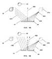
- FIG. 1schematically illustrates an endoscope system with a variable optical axis according to the one embodiment of the present invention.
- the endoscope devicecomprises an endoscope imaging device 11 and a three-dimensional display device 12 .
- the endoscope imaging device 11comprises a lens system 13 , 14 , an imaging unit 15 , and an image processing unit 16 .
- the lens systemincludes an objective lens 13 , and a variable focal length MMAL 14 , optically coupled to the objective lens 13 , configured to change the focal plane by changing the focal length of the MMAL 14 .
- the light delivery system 17 with a light source 18illuminates an object of interest 19 .
- the imaging unit 15receives two-dimensional images of an object 19 with different focal planes that are shifted by changing the focal length of the variable focal length MMAL 14 .
- the image depth of the focal planeis obtained from the focal length of the variable focal length MMAL.
- the image processing unit 16extracts substantially in-focus pixels or areas from original two-dimensional images taken at different focal planes to generate in-focus depthwise images and provides depth information of the object of interest 19 .
- a set of in-focus depthwise images taken at different focal lengths with a fast imaging raterepresents the object at a given moment.
- the image processing unit 16can generate an all-in-focus image with depth information as well.
- the imaging deviceis communicatively connected to the three-dimensional display device. Since the focal plane and the optical axis of the MMAL can be changed without macroscopic movements, the arrangement of optical elements in FIG. 1 requires a small space and allows a compact size endoscope imaging system, which is desirable to achieve a minimal invasive endoscopic procedure.
- FIG. 2illustrates an endoscope imaging device with a variable length MMALs can be employed.
- FIG. 2illustrates an endoscope imaging device with a variable optical axis and a variable magnification (a variable field of view) according to the other embodiment of the present invention.
- the endoscope imaging device 21comprises a lens system, an imaging unit 22 , and an image processing unit 23 .
- the lens systemcomprises an objective lens 24 , and a variable focal length MMAL 25 , optically coupled to the objective lens 24 , configured to change the focal plane by changing the focal length of the MMAL 25 .
- the lens systemalso comprises an auxiliary lens 26 or group of lenses to change the field of view and image resolution. Further, the lens system comprises one or more auxiliary lenses for increasing the numerical aperture of the imaging system.
- the lens systemcan comprise the second variable focal length MMAL 27 for the variable magnification of the object.
- the first and second variable focal length MMAL 25 , 27are optically coupled. They are controlled to change the magnification of the object (size of field of view), wherein the image of an object is optically magnified and to change the focal plane to form two-dimensional images in-focus at a given magnification.
- the objective lens 24 and the auxiliary lens 26provide additional magnification.
- the magnificationis adjusted without macroscopic movements of the lens system or time delay since each micromirror 28 of the variable focal length MMALs 25 and 27 is adjusted independently and actuated by electrostatic and/or electromagnetic force.
- the image processing unit 23generates a set of in-focus depthwise image with depth information or an all-in-focus image with depth information using the two-dimensional images with depth information received from the imaging unit 22 .
- the variable focal length MMAL 25 and 27changes their focal lengths so fast that the imaging processes are achieved faster than the persistence rate of the human eye.
- the light delivery system 29illuminates an object of interest. Further, by controlling individual micromirrors of variable focal length MMALs, the optical axis of the lens system can be adjusted, as will be explained in FIG. 4 . Since the MMAL can be made to have a small aperture and the magnification and optical axis can be adjusted without macroscopic movements of the lens system, the arrangement of optical elements in FIG. 2 requires a small space and allows a compact size endoscope imaging system, which is desirable to achieve a minimal invasive endoscopic procedure.
- FIG. 3shows how a MMAL 31 takes two-dimensional images 32 A, 32 B, 32 C with the focal planes 33 A, 33 B, 33 C.
- the MMAL 31comprises a plurality of micromirrors 34 .
- Each micromirror 34is controlled to change the focal length of the variable focal length MMAL 31 .
- the focal length of the MMAL 31is changed by rotation and translation of each micromirror 34 , which are controlled by electrostatic and/or electromagnetic force.
- Two-dimensional images 32 A, 32 B, 32 Care taken with the depth information which corresponds to the position of the focal plane.
- the two-dimensional image 32 Ahas in-focus image LI at the focal plane 33 A, which is the image of a portion L of an object 35 .
- Images MD, ND of portions M, N of an object 35are defocused.
- the image processing unitdetermines the in-focus pixels LI from the two-dimensional images 32 A.
- the two-dimensional image 32 A with depth informationgives in-focus pixels LI corresponding to the focal plane 33 A.
- the two-dimensional images 32 B, 32 C with the second and third focal plane 33 B, 33 Care processed in the same manner as the first focal plane 33 A to get in-focus images with depth information.
- FIG. 4shows how the optical axis of the MMAL changes.
- a bunch of lightis focused by the MMAL 41 .
- a cube object 42is imaged onto the image plane.
- the light 43 A from the object 42is reflected by each of the micromirror 44 .
- the reflected light 45 Ais focused onto the focal point 46 A of the image and finally makes an image of a cube 47 A in the image sensor.
- the optical axisis defined as a surface normal direction 48 A of a micromirror 44 .
- the MMALcan make a different image 47 B from a different object 49 without macroscopic movements.
- the MMALaccepts the light 43 B from the sphere 49 .
- the reflected light 45 Bis focused onto a focal point 46 B and makes the image of the sphere 47 B.
- the optical axisis changed by an angle and becomes the surface normal direction 48 B of a micromirror.
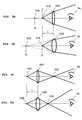
- FIGS. 5A-5Dillustrate the general principle regarding the distance or depth of an image formed by a lens and the focal length of the lens.
- a lensmeans an optical element that focuses light, and is not confined to a refractive type lens.
- FIGS. 5A-5Ddemonstrate that the position of a virtual or real image changes according to the focal length of a lens, and the position of the image will change continuously as the focal length varies continuously.
- FIG. 5Ashows that the light from an object 51 A passes through a lens 52 A and then diverges with a different angle.
- FIG. 5Bis a similar diagram for a lens 52 B having a shorter focal length.
- the light refracted by the lens 52 A, 52 Bforms a virtual image 53 A, 53 B.
- the viewer 54sees the refracted light, the viewer perceives the object 51 A, 51 B, which are positioned at point P, as existing at point Q, Q′.
- FIG. 5Cshows that the light from an object 51 C passes through a lens 52 C and then converges to form a real image 53 C.
- FIG. 5Dis a similar diagram for a lens 52 D having a shorter focal length. When the viewer 54 sees an object 51 C, 51 D through the lens 52 C, 52 D, the viewer perceives the object 51 C, 51 D as the real image 53 C, 53 D.
- FIGS. 5A and 5Bshow that the virtual image 53 A is nearer to the viewer 54 with the lens 52 A having a longer focal length, and the virtual image 53 B is farther from the viewer 54 with the lens 52 B having a shorter focal length.
- FIGS. 5C and 5Dshow that the real image 53 C is nearer to the viewer 54 with the lens 52 C having a longer focal length, and the real image 53 D is farther from the viewer 54 with the lens 52 D having a shorter focal length.
- FIG. 6schematically shows a three-dimensional display device 61 according to one embodiment of the present invention.
- the three-dimensional display device 61includes a two-dimensional display 62 and a variable focal length MMAL 63 .
- the two-dimensional display 62displays one in-focus depthwise image 64 at a time, which is received from the image processing unit 16 (or 27 ) or a storage space of the three-dimensional imaging system.
- the two-dimensional display 62displays only pixels that should be imaged at the same depth at a given frame.
- the variable focal length MMAL 63receives light from the two-dimensional display 62 and forms a corresponding image at the required location in the space to generate a three-dimensional image.
- the location of the image formed in the spacedepends on depth information of the in-focus depthwise image, received from the image processing unit 16 (or 27 ) or the storage space of the three-dimensional imaging system, and is adjusted by changing the focal length of the variable focal length MMAL.
- the variable focal length MMAL 63are synchronized with the two-dimensional display 62 so that the variable focal length MMAL 63 can have a focal length corresponding to the depth information of the in-focus depthwise image 64 displayed in the two-dimensional display 62 .
- an three-dimensional image 65 of the objectis formed in the space accordingly and perceived as three-dimensional by a viewer 66 .
- FIGS. 7A-7Cshow how a two-dimensional display and a variable focal length MMAL displays three-dimensional images.
- an objectis represented by a set of in-focus depthwise images 71 A, 71 B, 71 C, each of which represents a portion of the object having the same image depth.
- the number of in-focus depthwise images representing the object at a given momentdepends on the depth resolution requirement, the refresh rate of the two-dimensional display 73 , and the focusing speed of the variable focal length MMAL 72 and may increase for a better image quality.
- the two-dimensional display 73displays one in-focus depthwise image at a time.
- the variable focal length MMAL 74receives light from the two-dimensional display 73 and forms a corresponding image 74 A, 74 B, 74 C at the required location in the space to generate a three-dimensional image.
- the set of in-focus depthwise images representing the object at a given momentare sequentially displayed in the two-dimensional display 73 within a unit time.
- focusing speed of the variable focal length MMAL 72 and refresh rate of the two-dimensional display 73must be equal or greater than the product of the persistent rate of the human eye and the number of depths.
- variable focal length MMAL 72 of the present inventionis capable of changing the focal length fast enough to generate realistic three-dimensional video images.
- FIG. 8Aschematically shows how a refractive Fresnel lens 81 A replaces an ordinary single-bodied lens 82 .
- FIG. 8Bshows how a reflective Fresnel lens 81 B, replacing an ordinary single-bodied mirror 83 , is formed with a MMAL.
- the MMALincludes a plurality of micromirrors 84 , and each micromirror 84 is controlled to form a reflective Fresnel lens 81 B and to change the focal length of the lens.
- variable focal length MMALIn order to obtain a bright and sharp image, the variable focal length MMAL must meet the two conditions for forming a lens. One is that all the rays should be converged into the focus, and the other is that the phase of the converged rays must be the same. Even though the rays have different optical path lengths, the same phase condition can be satisfied by adjusting the optical path length difference to be integer multiples of the wavelength of the light. Each facet converges rays to one point, and rays refracted or reflected by different facets have an optical path length difference of integer multiples of the incident light.
- the translational motion and/or the rotational motion of each of the micromirrorsare controlled to change the direction of light and to satisfy the phase condition of the light.
- variable focal length MMALis also an adaptive optical component compensating the aberration of the imaging system by controlling the translational motion and/or the rotational motion of each micromirror.
- FIGS. 9A and 9Bshow that the micromirrors 91 are arranged to form many concentric circles.
- the micromirrors 91are arranged in a flat plane as shown in FIG. 8B .
- variable focal length MMALmust meet the following requirements to be used in three-dimensional display and imaging system. First, it must have a focal length change speed fast enough for three-dimensional display. Second, it must have a large range of numerical aperture change, since the depth range that can be imaged depends on the range of numerical aperture change. Third, it needs to have a large diameter depending on constructions of three-dimensional displays.
- the MMALmeets three requirements.
- the response speed of the micromirror 91exceeds the persistent rate of the human eyes times the number of depths unless the depth resolution requirement is extremely high. It is possible to make the focal length change within hundreds of micro-seconds.
- the range of numerical aperture change of the MMALis large since the range of focal length variation of the MMAL is large. So, the MMAL can have a greater range of image depths, which is an essential requirement for a three-dimensional display. Also, the MMAL can have a large diameter. In contrast with a lens having a continuous shape, for which it becomes difficult to make an ideal curved surface as the size becomes larger, there is no difficulty in enlarging the size of MMAL, since the MMAL comprises discrete micromirrors.
- the MMALis a reflective lens
- the optical system of the three-dimensional display devicecannot be aligned in a line.
- An optical arrangement, in which the reflected light is not blocked by the two-dimensional display,is required.
- FIG. 10shows an arrangement in which the three-dimensional display device 101 further includes a beam splitter 102 positioned in the path of light between a two-dimensional display 103 and a variable focal length MMAL 104 .
- the two-dimensional display 103 and the variable focal length MMAL 104are arranged parallel with each other.
- the beam splitter 102changes the direction of the light by 90°, and thus simulating an in-line optical arrangement.
- the MMALis positioned perpendicular to the light path.
- variable focal length MMAL 63is positioned so that the path of the light reflected by the variable focal length MMAL 63 is not blocked by the two-dimensional display 62 .
- the arrangement in FIG. 6has advantages of simple structure and wider field of view since the distance between the two-dimensional display and the variable focal length MMAL 63 is closer than that of the arrangement with the beam splitter 102 . However, it needs special consideration of the correction of the aberration induced by the obliquely positioned variable focal length MMAL 63 . The choice of either arrangement depends on the use of the display device.
- the three-dimensional display devicemay further include an auxiliary lens 105 having a predetermined focal length and positioned adjacent to the variable focal length MMAL 104 .
- the three-dimensional image 106is formed by the effective focal length of the variable focal length MMAL 103 and the auxiliary lens 105 .
- the auxiliary lens 105With the auxiliary lens 105 , the variable focusing range of the three-dimensional display device can be extended or changed to a desired range.
- a refractive type Fresnelcan be used as an auxiliary lens 105 .
- the variable focal length MMALs 63 , 104should have the size of the screen.
- the three-dimensional display devicemay further include an auxiliary lens 111 that magnifies the three-dimensional image 112 , in order to overcome the limitation in size.
- the auxiliary lens 111may be an ordinary refractive lens or a refractive Fresnel lens.
- the screen sizebecomes the size of the auxiliary lens 111 , which has a fixed focal length.
- a two-dimensional display 113 and a variable focal length MMAL 114can have a compact size that is much smaller than the size of the auxiliary lens 111 .
- the effective focal length of the three-dimensional display deviceis varied by changing the focal length of the variable focal lens 114 .
- the focal length of the variable focal length MMAL 114may be controlled to be fixed.
- the three-dimensional display devicecan be easily converted into a two-dimensional display device. In two-dimensional mode, three-dimensional display shows two-dimensional images at a different distance from the view.
- Method for displaying a three-dimensional imagemay be one using a virtual image as illustrated in FIGS. 5A and 5B , or one using a real image as illustrated in FIGS. 5C and 5D .
- the method using a real imagehas an advantage that it enables more realistic display since the image is generated closer to the viewer, and has a disadvantage that the range of display is limited between the viewer and the screen.
- the imageis generated behind the screen. This method has an advantage that it can display an image having depth ranging from the screen to the infinity.
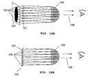
- FIGS. 12A and 12Bshow a three-dimensional display device according to the other embodiment of the present invention.
- FIG. 12Ashows how a three-dimensional display device, which has many variable focal length lenses 121 corresponding to pixels 122 of a two-dimensional display 123 , operates to display a three-dimensional image 124 .
- the partial image displayed by each pixel 122is imaged at its image depth by the variable focal length lens 121 corresponding to the pixel 122 . Since the partial image displayed by each pixel is individually handled by the corresponding variable focal length lens, dividing an image into depthwise images and displaying the depthwise images are not required, and thus this embodiment does not need a high speed two-dimensional display or a high speed variable focal length lens.
- a two-dimensional display having a usual speedcan be used.
- the size of the variable focal length lens 121is similar to that of the pixel 122 .
- FIG. 12Bshows schematically a three-dimensional display device 125 .
- the three-dimensional display device 125includes a two-dimensional display having a plurality of pixels 126 , and a plurality of variable focal length MMALs 127 .
- Each of the variable focal length MMALs 127corresponds to each of the pixel 126 .
- the focusing speed of the variable focal length MMAL 127is at least persistent rate of the human eyes and each of the variable focal length MMALs 127 reflect light from the two-dimensional display.
- the focal length of each of the variable focal length MMALs 127changes according to the image depth of an image displayed by each of the pixels 126 .
- the lens element 127is positioned so that the reflected light is not blocked by the two-dimensional display.
- Each of the pixels 126displays a portion of an all-in-focus image in a direction orthogonal with the device display direction 128 of the three-dimensional display device 125 .
- the all-in-focus imageis received from the image processing unit 16 (or 27 ) or a storage space of the three-dimensional imaging system.
- Each of the lens elements 127is positioned at an angle of 45° with respect to the display direction of the pixels 126 and the device display direction 128 .
- a three-dimensional image 129is formed by the lens elements 127 . Notwithstanding this complex arrangement, the MMAL is used because its range of numerical aperture change is large.
- FIG. 13shows a three-dimensional display method according to the invention.
- step 131an in-focus depthwise image is displayed in a two-dimensional display.
- step 132the corresponding image is formed in the space by receiving light from the two-dimensional display and reflecting the light to the required location using depth information of the in-focus depthwise image.
- steps 131 and 132are repeated for the number of depths within a unit time.
- Each of in-focus depthwise imagesrepresents the portion of an object having the same image depth.
- a set of in-focus depthwise images representing the object at a given momentare sequentially displayed by the above steps, a three-dimensional image is formed in the space accordingly.
- the focusing speed of a variable focal length lensis at least equal to the product of the persistent rate of the human eye and the number of depths.
- the step of forming three-dimensional image 132is performed with a variable focal length MMAL.
Landscapes
- Physics & Mathematics (AREA)
- Engineering & Computer Science (AREA)
- Health & Medical Sciences (AREA)
- Life Sciences & Earth Sciences (AREA)
- General Physics & Mathematics (AREA)
- Optics & Photonics (AREA)
- Medical Informatics (AREA)
- Multimedia (AREA)
- Signal Processing (AREA)
- Surgery (AREA)
- Biomedical Technology (AREA)
- Nuclear Medicine, Radiotherapy & Molecular Imaging (AREA)
- Pathology (AREA)
- Radiology & Medical Imaging (AREA)
- Biophysics (AREA)
- Heart & Thoracic Surgery (AREA)
- Molecular Biology (AREA)
- Animal Behavior & Ethology (AREA)
- General Health & Medical Sciences (AREA)
- Public Health (AREA)
- Veterinary Medicine (AREA)
- High Energy & Nuclear Physics (AREA)
- Human Computer Interaction (AREA)
Abstract
Description
Claims (30)
Priority Applications (2)
| Application Number | Priority Date | Filing Date | Title |
|---|---|---|---|
| US11/314,408US7751694B2 (en) | 2004-02-13 | 2005-12-20 | Three-dimensional endoscope imaging and display system |
| US11/382,707US7742232B2 (en) | 2004-04-12 | 2006-05-11 | Three-dimensional imaging system |
Applications Claiming Priority (7)
| Application Number | Priority Date | Filing Date | Title |
|---|---|---|---|
| US10/778,281US7077523B2 (en) | 2004-02-13 | 2004-02-13 | Three-dimensional display using variable focusing lens |
| US10/822,414US7068416B2 (en) | 2004-04-12 | 2004-04-12 | Three-dimensional imaging device |
| US10/872,241US7382516B2 (en) | 2004-06-18 | 2004-06-18 | Discretely controlled micromirror with multi-level positions |
| US10/893,039US7239438B2 (en) | 2004-07-16 | 2004-07-16 | Variable focal length lens and lens array comprising discretely controlled micromirrors |
| US10/979,624US7261417B2 (en) | 2004-02-13 | 2004-11-02 | Three-dimensional integral imaging and display system using variable focal length lens |
| US10/983,353US7267447B2 (en) | 2004-05-27 | 2004-11-08 | Variable focal length lens comprising micromirrors |
| US11/314,408US7751694B2 (en) | 2004-02-13 | 2005-12-20 | Three-dimensional endoscope imaging and display system |
Related Parent Applications (7)
| Application Number | Title | Priority Date | Filing Date |
|---|---|---|---|
| US10/778,281Continuation-In-PartUS7077523B2 (en) | 2004-02-13 | 2004-02-13 | Three-dimensional display using variable focusing lens |
| US10/822,414Continuation-In-PartUS7068416B2 (en) | 2004-02-13 | 2004-04-12 | Three-dimensional imaging device |
| US10/872,241Continuation-In-PartUS7382516B2 (en) | 2004-02-13 | 2004-06-18 | Discretely controlled micromirror with multi-level positions |
| US10/893,039Continuation-In-PartUS7239438B2 (en) | 2004-02-13 | 2004-07-16 | Variable focal length lens and lens array comprising discretely controlled micromirrors |
| US10/979,624Continuation-In-PartUS7261417B2 (en) | 2004-02-13 | 2004-11-02 | Three-dimensional integral imaging and display system using variable focal length lens |
| US10/983,353Continuation-In-PartUS7267447B2 (en) | 2004-02-13 | 2004-11-08 | Variable focal length lens comprising micromirrors |
| US11/319,987Continuation-In-PartUS7410266B2 (en) | 2004-03-22 | 2005-12-28 | Three-dimensional imaging system for robot vision |
Related Child Applications (2)
| Application Number | Title | Priority Date | Filing Date |
|---|---|---|---|
| US11/300,205Continuation-In-PartUS7580178B2 (en) | 2004-02-13 | 2005-12-13 | Image-guided microsurgery system and method |
| US11/382,707Continuation-In-PartUS7742232B2 (en) | 2004-04-12 | 2006-05-11 | Three-dimensional imaging system |
Publications (2)
| Publication Number | Publication Date |
|---|---|
| US20060120706A1 US20060120706A1 (en) | 2006-06-08 |
| US7751694B2true US7751694B2 (en) | 2010-07-06 |
Family
ID=36261390
Family Applications (1)
| Application Number | Title | Priority Date | Filing Date |
|---|---|---|---|
| US11/314,408Active2026-03-27US7751694B2 (en) | 2004-02-13 | 2005-12-20 | Three-dimensional endoscope imaging and display system |
Country Status (1)
| Country | Link |
|---|---|
| US (1) | US7751694B2 (en) |
Cited By (5)
| Publication number | Priority date | Publication date | Assignee | Title |
|---|---|---|---|---|
| US9420243B2 (en) | 2012-05-18 | 2016-08-16 | Thomson Licensing | Native three-color images and high dynamic range images |
| US9456752B2 (en) | 2013-03-14 | 2016-10-04 | Aperture Diagnostics Ltd. | Full-field three-dimensional surface measurement |
| US11153696B2 (en) | 2017-02-14 | 2021-10-19 | Virtual 3-D Technologies Corp. | Ear canal modeling using pattern projection |
| US11743596B1 (en)* | 2020-05-22 | 2023-08-29 | Verily Life Sciences Llc | Adaptive brightness non-uniformity correction in endoscope visualization |
| DE102023109944B3 (en) | 2023-04-19 | 2024-04-25 | Carl Zeiss Meditec Ag | Fiber endoscope for stereoscopic imaging and method for acquiring stereoscopic image data |
Families Citing this family (39)
| Publication number | Priority date | Publication date | Assignee | Title |
|---|---|---|---|---|
| US7350922B2 (en)* | 2004-02-13 | 2008-04-01 | Angstrom, Inc. | Three-dimensional display using variable focal length micromirror array lens |
| US20050207486A1 (en)* | 2004-03-18 | 2005-09-22 | Sony Corporation | Three dimensional acquisition and visualization system for personal electronic devices |
| US7489434B2 (en) | 2007-05-02 | 2009-02-10 | Angstrom, Inc. | Hybrid micromirror array lens for reducing chromatic aberration |
| US7619807B2 (en)* | 2004-11-08 | 2009-11-17 | Angstrom, Inc. | Micromirror array lens with optical surface profiles |
| US7668450B2 (en)* | 2005-01-28 | 2010-02-23 | Stryker Corporation | Endoscope with integrated light source |
| US8029439B2 (en) | 2005-01-28 | 2011-10-04 | Stryker Corporation | Disposable attachable light source unit for an endoscope |
| US7822000B2 (en)* | 2005-06-30 | 2010-10-26 | Symbol Technologies, Inc. | Time division multiplexing for access ports in a wireless network |
| US7929801B2 (en)* | 2005-08-15 | 2011-04-19 | Sony Corporation | Depth information for auto focus using two pictures and two-dimensional Gaussian scale space theory |
| US20070189750A1 (en)* | 2006-02-16 | 2007-08-16 | Sony Corporation | Method of and apparatus for simultaneously capturing and generating multiple blurred images |
| US7616254B2 (en)* | 2006-03-16 | 2009-11-10 | Sony Corporation | Simple method for calculating camera defocus from an image scene |
| US7711201B2 (en)* | 2006-06-22 | 2010-05-04 | Sony Corporation | Method of and apparatus for generating a depth map utilized in autofocusing |
| US8077964B2 (en)* | 2007-03-19 | 2011-12-13 | Sony Corporation | Two dimensional/three dimensional digital information acquisition and display device |
| US9505606B2 (en)* | 2007-06-13 | 2016-11-29 | Angstrom, Inc. | MEMS actuator with discretely controlled multiple motions |
| US7605988B2 (en)* | 2007-07-23 | 2009-10-20 | Angstrom, Inc. | Compact image taking lens system with a lens-surfaced prism |
| US7589916B2 (en)* | 2007-08-10 | 2009-09-15 | Angstrom, Inc. | Micromirror array with iris function |
| JP2009063637A (en)* | 2007-09-04 | 2009-03-26 | Fujifilm Corp | Optical scanning probe, optical scanning probe device, and optical scanning probe control method |
| US20090185067A1 (en)* | 2007-12-21 | 2009-07-23 | Stereo Display, Inc. | Compact automatic focusing camera |
| US8810908B2 (en)* | 2008-03-18 | 2014-08-19 | Stereo Display, Inc. | Binoculars with micromirror array lenses |
| US8280194B2 (en)* | 2008-04-29 | 2012-10-02 | Sony Corporation | Reduced hardware implementation for a two-picture depth map algorithm |
| US8622557B2 (en)* | 2008-05-20 | 2014-01-07 | Stereo Display, Inc. | Micromirror array lens with self-tilted micromirrors |
| US20090303569A1 (en)* | 2008-05-20 | 2009-12-10 | Stereo Didplay, Inc. | Self-tilted micromirror device |
| US8553093B2 (en)* | 2008-09-30 | 2013-10-08 | Sony Corporation | Method and apparatus for super-resolution imaging using digital imaging devices |
| US8194995B2 (en)* | 2008-09-30 | 2012-06-05 | Sony Corporation | Fast camera auto-focus |
| KR101753801B1 (en)* | 2010-06-10 | 2017-07-04 | 엘지디스플레이 주식회사 | Liquid crystal display device and driving method for thereof |
| US10156722B2 (en) | 2010-12-24 | 2018-12-18 | Magic Leap, Inc. | Methods and systems for displaying stereoscopy with a freeform optical system with addressable focus for virtual and augmented reality |
| US9983685B2 (en) | 2011-01-17 | 2018-05-29 | Mediatek Inc. | Electronic apparatuses and methods for providing a man-machine interface (MMI) |
| US8670023B2 (en)* | 2011-01-17 | 2014-03-11 | Mediatek Inc. | Apparatuses and methods for providing a 3D man-machine interface (MMI) |
| KR20120105169A (en)* | 2011-03-15 | 2012-09-25 | 삼성전자주식회사 | Method of operating a three-dimensional image sensor including a plurality of depth pixels |
| JP2013150249A (en)* | 2012-01-23 | 2013-08-01 | Sony Corp | Image processing device, image processing method and program |
| JP2014236340A (en)* | 2013-05-31 | 2014-12-15 | 株式会社東芝 | Image processing device, method, program, and stereoscopic image display device |
| US9857591B2 (en) | 2014-05-30 | 2018-01-02 | Magic Leap, Inc. | Methods and system for creating focal planes in virtual and augmented reality |
| CN110376743B (en) | 2014-01-31 | 2022-03-04 | 奇跃公司 | Multi-focus display system and method |
| EP4099274B1 (en)* | 2014-01-31 | 2024-03-06 | Magic Leap, Inc. | Multi-focal display system and method |
| EP3149528B1 (en) | 2014-05-30 | 2023-06-07 | Magic Leap, Inc. | Methods and system for creating focal planes in virtual and augmented reality |
| AU2015266670B2 (en) | 2014-05-30 | 2019-05-09 | Magic Leap, Inc. | Methods and systems for displaying stereoscopy with a freeform optical system with addressable focus for virtual and augmented reality |
| US10473935B1 (en)* | 2016-08-10 | 2019-11-12 | Meta View, Inc. | Systems and methods to provide views of virtual content in an interactive space |
| CN107391631A (en)* | 2017-07-10 | 2017-11-24 | 国家电网公司 | A kind of electric transmission line channel solid space monitoring and fast ranging method |
| CN109357628B (en)* | 2018-10-23 | 2024-06-21 | 合肥的卢深视科技有限公司 | High-precision three-dimensional image acquisition method and device for region of interest |
| CN113143169B (en)* | 2020-01-22 | 2024-07-23 | 沈阳华慧高新技术有限公司 | Structured light binocular endoscope |
Citations (92)
| Publication number | Priority date | Publication date | Assignee | Title |
|---|---|---|---|---|
| US2002376A (en) | 1931-03-16 | 1935-05-21 | Mannheimer Manfred | Searchlight reflector |
| US3520587A (en) | 1967-03-29 | 1970-07-14 | Olympus Optical Co | Stereoscopic endoscope |
| US4407567A (en) | 1978-05-05 | 1983-10-04 | Quantel S.A. | Objective having a variable focal length |
| US4834512A (en) | 1984-12-21 | 1989-05-30 | Hughes Aircraft Company | Three-dimensional display |
| US5004319A (en) | 1988-12-29 | 1991-04-02 | The United States Of America As Represented By The Department Of Energy | Crystal diffraction lens with variable focal length |
| US5212555A (en) | 1991-12-17 | 1993-05-18 | Texas Instruments Incorporated | Image capture with spatial light modulator and single-cell photosensor |
| US5307170A (en)* | 1990-10-29 | 1994-04-26 | Kabushiki Kaisha Toshiba | Video camera having a vibrating image-processing operation |
| US5369433A (en) | 1991-04-05 | 1994-11-29 | Rank Cintel Limited | Recording video signals on cinematographic film using a deformable mirror device |
| US5402407A (en) | 1992-06-19 | 1995-03-28 | Sony Corporation | Optical pickup apparatus and method for adjusting optical axis thereof |
| US5467121A (en) | 1991-10-11 | 1995-11-14 | Coherent Hull, Ltd. | Method and apparatus for dot matrix writing using a continous wave laser |
| JPH0843881A (en) | 1994-07-29 | 1996-02-16 | Nikon Corp | camera |
| US5612736A (en) | 1995-06-07 | 1997-03-18 | Nview Corporation | Stylus position sensing and digital camera with a digital micromirror device |
| US5673147A (en) | 1995-04-18 | 1997-09-30 | Mckinley Optics, Inc. | Stereo video endoscope objective lens systems |
| US5696619A (en) | 1995-02-27 | 1997-12-09 | Texas Instruments Incorporated | Micromechanical device having an improved beam |
| US5751341A (en) | 1993-01-05 | 1998-05-12 | Vista Medical Technologies, Inc. | Stereoscopic endoscope system |
| JPH1169209A (en) | 1997-08-22 | 1999-03-09 | Minolta Co Ltd | Image-pickup device |
| US5881034A (en) | 1996-08-20 | 1999-03-09 | Sony Corporation | Apparatus for driving objective lens |
| US5897195A (en) | 1997-12-09 | 1999-04-27 | Optical Gaging, Products, Inc. | Oblique led illuminator device |
| US5986811A (en) | 1995-06-07 | 1999-11-16 | Meso Scale Technologies Llp | Method of and apparatus for generating a 3-D image from a 2-D image having a changeable focusing micro-lens array |
| US6025951A (en) | 1996-11-27 | 2000-02-15 | National Optics Institute | Light modulating microdevice and method |
| US6028689A (en) | 1997-01-24 | 2000-02-22 | The United States Of America As Represented By The Secretary Of The Air Force | Multi-motion micromirror |
| US6064423A (en) | 1998-02-12 | 2000-05-16 | Geng; Zheng Jason | Method and apparatus for high resolution three dimensional display |
| US6084843A (en) | 1997-03-19 | 2000-07-04 | Sony Corporation | Optical recording and reproducing apparatus and method |
| US6104425A (en) | 1996-02-29 | 2000-08-15 | Matsushita Electric Industrial Co., Ltd. | Method and apparatus for transmitting television signals, method and apparatus for receiving television signals, and method and apparatus for transmitting/receiving television signals |
| US6111900A (en) | 1997-03-13 | 2000-08-29 | Ricoh Company, Ltd. | Solid-state laser apparatus and method with second harmonic wave features |
| US6123985A (en) | 1998-10-28 | 2000-09-26 | Solus Micro Technologies, Inc. | Method of fabricating a membrane-actuated charge controlled mirror (CCM) |
| US6282213B1 (en) | 1998-09-14 | 2001-08-28 | Interscience, Inc. | Tunable diode laser with fast digital line selection |
| US6288767B1 (en)* | 1996-06-07 | 2001-09-11 | Olympus Optical Company, Ltd | Imaging optical system |
| US6315423B1 (en) | 1999-07-13 | 2001-11-13 | Input/Output, Inc. | Micro machined mirror |
| US6329737B1 (en) | 1998-12-15 | 2001-12-11 | Iolon, Inc. | Rotary electrostatic microactuator |
| US20020018407A1 (en) | 2000-08-02 | 2002-02-14 | Hiraku Komoto | Optical pickup device |
| US20020102102A1 (en) | 2001-01-30 | 2002-08-01 | Yoji Watanabe | Focal-length adjusting unit for photographing apparatuses |
| US20020135673A1 (en) | 2000-11-03 | 2002-09-26 | Favalora Gregg E. | Three-dimensional display systems |
| JP2002288873A (en) | 2001-03-27 | 2002-10-04 | Ricoh Co Ltd | Optical information recording / reproducing device |
| US6498673B1 (en) | 2000-01-19 | 2002-12-24 | At&T Corp. | Micro-machined tunable delay line |
| US6503195B1 (en)* | 1999-05-24 | 2003-01-07 | University Of North Carolina At Chapel Hill | Methods and systems for real-time structured light depth extraction and endoscope using real-time structured light depth extraction |
| US6507366B1 (en) | 1998-04-16 | 2003-01-14 | Samsung Electronics Co., Ltd. | Method and apparatus for automatically tracking a moving object |
| US20030058520A1 (en) | 2001-02-09 | 2003-03-27 | Kyoungsik Yu | Reconfigurable wavelength multiplexers and filters employing micromirror array in a gires-tournois interferometer |
| US6549730B1 (en) | 1999-09-29 | 2003-04-15 | Minolta Co., Ltd. | Focal position changeable spatial modulation unit and focus detection device |
| US20030071125A1 (en) | 2001-10-16 | 2003-04-17 | Samsung Electronics Co., Ltd. | Laser scanning unit |
| US6563105B2 (en) | 1999-06-08 | 2003-05-13 | University Of Washington | Image acquisition with depth enhancement |
| US20030174234A1 (en) | 2000-04-13 | 2003-09-18 | Tetsujiro Kondo | Imaging device and imaging method |
| US6625342B2 (en) | 2001-07-03 | 2003-09-23 | Network Photonics, Inc. | Systems and methods for overcoming stiction using a lever |
| US20030184843A1 (en) | 2001-04-03 | 2003-10-02 | Cidra Corporation | Optical blocking filter having an array of micro-mirrors |
| US6650461B2 (en) | 1995-12-01 | 2003-11-18 | Seiko Epson Corporation | Method of manufacturing spatial light modulator and electronic device employing it |
| US6649852B2 (en) | 2001-08-14 | 2003-11-18 | Motorola, Inc. | Micro-electro mechanical system |
| US20040009683A1 (en) | 2002-07-04 | 2004-01-15 | Kabushiki Kaisha Toshiba | Method for connecting electronic device |
| US20040012460A1 (en) | 2002-07-16 | 2004-01-22 | Korea Advanced Institute Of Science And Technology | Electromagnetically actuated micromirror actuator and fabrication method thereof |
| US20040021802A1 (en) | 2002-01-23 | 2004-02-05 | Kazutora Yoshino | Color 3D image display |
| US20040052180A1 (en) | 2000-03-28 | 2004-03-18 | Lg Electronics Inc. | Optical pick-up actuator |
| US6711319B2 (en) | 2001-09-07 | 2004-03-23 | Agilent Technologies, Inc. | Optical switch with converging optical element |
| US6741384B1 (en) | 2003-04-30 | 2004-05-25 | Hewlett-Packard Development Company, L.P. | Control of MEMS and light modulator arrays |
| US6749346B1 (en) | 1995-11-07 | 2004-06-15 | The Board Of Trustees Of The Leland Stanford Junior University | Miniature scanning confocal microscope |
| US6784771B1 (en) | 2001-07-24 | 2004-08-31 | New Peregrine, Inc. | MEMS optical mirror array |
| US6798570B1 (en) | 1999-11-22 | 2004-09-28 | Gary Greenberg | Apparatus and methods for creating real-time 3-D images and constructing 3-D models of an object imaged in an optical system |
| US20040246362A1 (en) | 2003-05-12 | 2004-12-09 | Minolta Co., Ltd. | Taking lens apparatus |
| US20040252958A1 (en) | 2003-06-10 | 2004-12-16 | Abu-Ageel Nayef M. | Light guide array, fabrication methods and optical system employing same |
| US6833938B2 (en) | 2000-01-26 | 2004-12-21 | Olympus Corporation | Variable hologram element, and optical device using the same |
| US20050024736A1 (en) | 2003-01-29 | 2005-02-03 | Bakin Dmitry V. | Optical cross-connect switch with telecentric lens and multi-surface optical element |
| US20050057812A1 (en) | 2003-01-13 | 2005-03-17 | Raber Peter E. | Variable focus system |
| US6885819B2 (en) | 2002-02-19 | 2005-04-26 | Ricoh Company, Ltd. | Camera, device for capturing object image, automatic focus adjusting system and method for adjusting automatic focus for the same |
| US6900901B2 (en) | 2000-06-26 | 2005-05-31 | Fuji Photo Film Co., Ltd. | Image recording device |
| US6900922B2 (en) | 2003-02-24 | 2005-05-31 | Exajoule, Llc | Multi-tilt micromirror systems with concealed hinge structures |
| US6906848B2 (en) | 2003-02-24 | 2005-06-14 | Exajoule, Llc | Micromirror systems with concealed multi-piece hinge structures |
| US6906849B1 (en) | 2004-05-14 | 2005-06-14 | Fujitsu Limited | Micro-mirror element |
| US20050136663A1 (en) | 2003-12-19 | 2005-06-23 | Agency For Science, Technology And Research | Single-crystal-silicon 3D micromirror |
| US6914712B2 (en) | 2002-09-26 | 2005-07-05 | Seiko Epson Corporation | Mirror device, optical switch, electronic instrument and mirror device driving method |
| US6919982B2 (en) | 2002-04-17 | 2005-07-19 | Ricoh Company, Ltd. | Optical path deflecting element, optical path deflecting apparatus, image displaying apparatus, optical element and manufacturing method thereof |
| US20050174625A1 (en) | 1995-06-19 | 2005-08-11 | Huibers Andrew G. | Double substrate reflective spatial light modulator with self-limiting micro-mechanical elements |
| US20050180019A1 (en) | 2004-02-13 | 2005-08-18 | Cho Gyoung I. | Three-dimensional integral imaging and display system using variable focal length lens |
| US6934073B1 (en) | 2004-05-28 | 2005-08-23 | Angstrom Inc. | Variable focal length lens comprising micromirrors with one degrees of freedom rotation and one degree of freedom translation |
| US6934072B1 (en) | 2004-05-27 | 2005-08-23 | Angstrom Inc. | Variable focal length lens comprising micromirrors with two degrees of freedom rotation and one degree of freedom translation |
| US6943950B2 (en) | 2000-08-07 | 2005-09-13 | Texas Instruments Incorporated | Two-dimensional blazed MEMS grating |
| US6949069B2 (en) | 2000-06-30 | 2005-09-27 | Inner Vision Imaging, L.L.C. | Endoscope |
| US20050212856A1 (en) | 2002-02-20 | 2005-09-29 | Stephen Temple | Fluid pumping and droplet deposition apparatus |
| US20050225884A1 (en) | 2004-04-12 | 2005-10-13 | Gim Dong W | Three-dimensional imaging device |
| US20050224695A1 (en) | 2003-02-25 | 2005-10-13 | Yoshihiro Mushika | Optical sensor |
| US20050231792A1 (en) | 2004-04-14 | 2005-10-20 | Christine Alain | Light modulating microdevice |
| US6958777B1 (en) | 2000-09-29 | 2005-10-25 | Ess Technology, Inc. | Exposure control in electromechanical imaging devices |
| US6970284B1 (en) | 2004-05-27 | 2005-11-29 | Angstrom Inc. | Variable focusing lens comprising micromirrors with one degree of freedom rotation |
| US20050264870A1 (en) | 2004-05-27 | 2005-12-01 | Angstrom Inc. | Variable focal length lens comprising micromirrors |
| US20060012852A1 (en) | 2004-07-16 | 2006-01-19 | Angstrom Inc. & Stereo Display Inc. | Variable focal length lens and lens array comprising discretely controlled micromirrors |
| US20060012766A1 (en) | 2004-07-13 | 2006-01-19 | Klosner Marc A | Versatile maskless lithography system with multiple resolutions |
| US6995909B1 (en) | 1999-10-06 | 2006-02-07 | Matsushita Electric Industrial Co., Ltd. | Lens, optical head, optical information writing/reading apparatus and optical information recording medium writing/reading method |
| US20060028709A1 (en) | 2004-08-09 | 2006-02-09 | Stereo Display, Inc. | Two-dimensional image projection system |
| US6999226B2 (en) | 2004-05-28 | 2006-02-14 | Angstrom Inc. | Variable focal length lens comprising micromirrors with one degree of freedom translation |
| US7031046B2 (en) | 2004-05-27 | 2006-04-18 | Angstrom Inc. | Variable focal length lens comprising micromirrors with two degrees of freedom rotation |
| US7077523B2 (en) | 2004-02-13 | 2006-07-18 | Angstorm Inc. | Three-dimensional display using variable focusing lens |
| US20060187524A1 (en) | 1998-03-02 | 2006-08-24 | Micronic Laser Systems Ab | Pattern generator diffractive mirror methods and systems |
| US20060209439A1 (en) | 2004-04-12 | 2006-09-21 | Stereo Display, Inc. | Three-dimensional imaging system |
| US7161729B2 (en) | 2004-05-28 | 2007-01-09 | Angstrom Inc. | Array of micromirror array lenses |
| US7212330B2 (en)* | 2004-03-22 | 2007-05-01 | Angstrom, Inc. | Three-dimensional imaging system for pattern recognition |
Family Cites Families (1)
| Publication number | Priority date | Publication date | Assignee | Title |
|---|---|---|---|---|
| JPH11168134A (en)* | 1997-12-03 | 1999-06-22 | Shin Etsu Chem Co Ltd | Electrostatic suction device and method of manufacturing the same |
- 2005
- 2005-12-20USUS11/314,408patent/US7751694B2/enactiveActive
Patent Citations (96)
| Publication number | Priority date | Publication date | Assignee | Title |
|---|---|---|---|---|
| US2002376A (en) | 1931-03-16 | 1935-05-21 | Mannheimer Manfred | Searchlight reflector |
| US3520587A (en) | 1967-03-29 | 1970-07-14 | Olympus Optical Co | Stereoscopic endoscope |
| US4407567A (en) | 1978-05-05 | 1983-10-04 | Quantel S.A. | Objective having a variable focal length |
| US4834512A (en) | 1984-12-21 | 1989-05-30 | Hughes Aircraft Company | Three-dimensional display |
| US5004319A (en) | 1988-12-29 | 1991-04-02 | The United States Of America As Represented By The Department Of Energy | Crystal diffraction lens with variable focal length |
| US5307170A (en)* | 1990-10-29 | 1994-04-26 | Kabushiki Kaisha Toshiba | Video camera having a vibrating image-processing operation |
| US5369433A (en) | 1991-04-05 | 1994-11-29 | Rank Cintel Limited | Recording video signals on cinematographic film using a deformable mirror device |
| US5467121A (en) | 1991-10-11 | 1995-11-14 | Coherent Hull, Ltd. | Method and apparatus for dot matrix writing using a continous wave laser |
| US5212555A (en) | 1991-12-17 | 1993-05-18 | Texas Instruments Incorporated | Image capture with spatial light modulator and single-cell photosensor |
| US5402407A (en) | 1992-06-19 | 1995-03-28 | Sony Corporation | Optical pickup apparatus and method for adjusting optical axis thereof |
| US5751341A (en) | 1993-01-05 | 1998-05-12 | Vista Medical Technologies, Inc. | Stereoscopic endoscope system |
| JPH0843881A (en) | 1994-07-29 | 1996-02-16 | Nikon Corp | camera |
| US5696619A (en) | 1995-02-27 | 1997-12-09 | Texas Instruments Incorporated | Micromechanical device having an improved beam |
| US5673147A (en) | 1995-04-18 | 1997-09-30 | Mckinley Optics, Inc. | Stereo video endoscope objective lens systems |
| US5986811A (en) | 1995-06-07 | 1999-11-16 | Meso Scale Technologies Llp | Method of and apparatus for generating a 3-D image from a 2-D image having a changeable focusing micro-lens array |
| US5612736A (en) | 1995-06-07 | 1997-03-18 | Nview Corporation | Stylus position sensing and digital camera with a digital micromirror device |
| US20050174625A1 (en) | 1995-06-19 | 2005-08-11 | Huibers Andrew G. | Double substrate reflective spatial light modulator with self-limiting micro-mechanical elements |
| US6749346B1 (en) | 1995-11-07 | 2004-06-15 | The Board Of Trustees Of The Leland Stanford Junior University | Miniature scanning confocal microscope |
| US6650461B2 (en) | 1995-12-01 | 2003-11-18 | Seiko Epson Corporation | Method of manufacturing spatial light modulator and electronic device employing it |
| US6104425A (en) | 1996-02-29 | 2000-08-15 | Matsushita Electric Industrial Co., Ltd. | Method and apparatus for transmitting television signals, method and apparatus for receiving television signals, and method and apparatus for transmitting/receiving television signals |
| US6288767B1 (en)* | 1996-06-07 | 2001-09-11 | Olympus Optical Company, Ltd | Imaging optical system |
| US5881034A (en) | 1996-08-20 | 1999-03-09 | Sony Corporation | Apparatus for driving objective lens |
| US6025951A (en) | 1996-11-27 | 2000-02-15 | National Optics Institute | Light modulating microdevice and method |
| US6028689A (en) | 1997-01-24 | 2000-02-22 | The United States Of America As Represented By The Secretary Of The Air Force | Multi-motion micromirror |
| US6111900A (en) | 1997-03-13 | 2000-08-29 | Ricoh Company, Ltd. | Solid-state laser apparatus and method with second harmonic wave features |
| US6084843A (en) | 1997-03-19 | 2000-07-04 | Sony Corporation | Optical recording and reproducing apparatus and method |
| JPH1169209A (en) | 1997-08-22 | 1999-03-09 | Minolta Co Ltd | Image-pickup device |
| US5897195A (en) | 1997-12-09 | 1999-04-27 | Optical Gaging, Products, Inc. | Oblique led illuminator device |
| US6064423A (en) | 1998-02-12 | 2000-05-16 | Geng; Zheng Jason | Method and apparatus for high resolution three dimensional display |
| US20060187524A1 (en) | 1998-03-02 | 2006-08-24 | Micronic Laser Systems Ab | Pattern generator diffractive mirror methods and systems |
| US6507366B1 (en) | 1998-04-16 | 2003-01-14 | Samsung Electronics Co., Ltd. | Method and apparatus for automatically tracking a moving object |
| US6282213B1 (en) | 1998-09-14 | 2001-08-28 | Interscience, Inc. | Tunable diode laser with fast digital line selection |
| US6123985A (en) | 1998-10-28 | 2000-09-26 | Solus Micro Technologies, Inc. | Method of fabricating a membrane-actuated charge controlled mirror (CCM) |
| US6329737B1 (en) | 1998-12-15 | 2001-12-11 | Iolon, Inc. | Rotary electrostatic microactuator |
| US6503195B1 (en)* | 1999-05-24 | 2003-01-07 | University Of North Carolina At Chapel Hill | Methods and systems for real-time structured light depth extraction and endoscope using real-time structured light depth extraction |
| US6563105B2 (en) | 1999-06-08 | 2003-05-13 | University Of Washington | Image acquisition with depth enhancement |
| US6315423B1 (en) | 1999-07-13 | 2001-11-13 | Input/Output, Inc. | Micro machined mirror |
| US6549730B1 (en) | 1999-09-29 | 2003-04-15 | Minolta Co., Ltd. | Focal position changeable spatial modulation unit and focus detection device |
| US6995909B1 (en) | 1999-10-06 | 2006-02-07 | Matsushita Electric Industrial Co., Ltd. | Lens, optical head, optical information writing/reading apparatus and optical information recording medium writing/reading method |
| US6798570B1 (en) | 1999-11-22 | 2004-09-28 | Gary Greenberg | Apparatus and methods for creating real-time 3-D images and constructing 3-D models of an object imaged in an optical system |
| US6498673B1 (en) | 2000-01-19 | 2002-12-24 | At&T Corp. | Micro-machined tunable delay line |
| US6833938B2 (en) | 2000-01-26 | 2004-12-21 | Olympus Corporation | Variable hologram element, and optical device using the same |
| US20040052180A1 (en) | 2000-03-28 | 2004-03-18 | Lg Electronics Inc. | Optical pick-up actuator |
| US20030174234A1 (en) | 2000-04-13 | 2003-09-18 | Tetsujiro Kondo | Imaging device and imaging method |
| US6900901B2 (en) | 2000-06-26 | 2005-05-31 | Fuji Photo Film Co., Ltd. | Image recording device |
| US6949069B2 (en) | 2000-06-30 | 2005-09-27 | Inner Vision Imaging, L.L.C. | Endoscope |
| US20020018407A1 (en) | 2000-08-02 | 2002-02-14 | Hiraku Komoto | Optical pickup device |
| US6943950B2 (en) | 2000-08-07 | 2005-09-13 | Texas Instruments Incorporated | Two-dimensional blazed MEMS grating |
| US6958777B1 (en) | 2000-09-29 | 2005-10-25 | Ess Technology, Inc. | Exposure control in electromechanical imaging devices |
| US7023466B2 (en) | 2000-11-03 | 2006-04-04 | Actuality Systems, Inc. | Three-dimensional display systems |
| US20020135673A1 (en) | 2000-11-03 | 2002-09-26 | Favalora Gregg E. | Three-dimensional display systems |
| US6658208B2 (en) | 2001-01-30 | 2003-12-02 | Olympus Optical Co., Ltd. | Focal-length adjusting unit for photographing apparatuses |
| US20020102102A1 (en) | 2001-01-30 | 2002-08-01 | Yoji Watanabe | Focal-length adjusting unit for photographing apparatuses |
| US20030058520A1 (en) | 2001-02-09 | 2003-03-27 | Kyoungsik Yu | Reconfigurable wavelength multiplexers and filters employing micromirror array in a gires-tournois interferometer |
| JP2002288873A (en) | 2001-03-27 | 2002-10-04 | Ricoh Co Ltd | Optical information recording / reproducing device |
| US20030184843A1 (en) | 2001-04-03 | 2003-10-02 | Cidra Corporation | Optical blocking filter having an array of micro-mirrors |
| US6625342B2 (en) | 2001-07-03 | 2003-09-23 | Network Photonics, Inc. | Systems and methods for overcoming stiction using a lever |
| US6784771B1 (en) | 2001-07-24 | 2004-08-31 | New Peregrine, Inc. | MEMS optical mirror array |
| US6649852B2 (en) | 2001-08-14 | 2003-11-18 | Motorola, Inc. | Micro-electro mechanical system |
| US6711319B2 (en) | 2001-09-07 | 2004-03-23 | Agilent Technologies, Inc. | Optical switch with converging optical element |
| US20030071125A1 (en) | 2001-10-16 | 2003-04-17 | Samsung Electronics Co., Ltd. | Laser scanning unit |
| US20040021802A1 (en) | 2002-01-23 | 2004-02-05 | Kazutora Yoshino | Color 3D image display |
| US6885819B2 (en) | 2002-02-19 | 2005-04-26 | Ricoh Company, Ltd. | Camera, device for capturing object image, automatic focus adjusting system and method for adjusting automatic focus for the same |
| US20050212856A1 (en) | 2002-02-20 | 2005-09-29 | Stephen Temple | Fluid pumping and droplet deposition apparatus |
| US6919982B2 (en) | 2002-04-17 | 2005-07-19 | Ricoh Company, Ltd. | Optical path deflecting element, optical path deflecting apparatus, image displaying apparatus, optical element and manufacturing method thereof |
| US20040009683A1 (en) | 2002-07-04 | 2004-01-15 | Kabushiki Kaisha Toshiba | Method for connecting electronic device |
| US20040012460A1 (en) | 2002-07-16 | 2004-01-22 | Korea Advanced Institute Of Science And Technology | Electromagnetically actuated micromirror actuator and fabrication method thereof |
| US6914712B2 (en) | 2002-09-26 | 2005-07-05 | Seiko Epson Corporation | Mirror device, optical switch, electronic instrument and mirror device driving method |
| US20050057812A1 (en) | 2003-01-13 | 2005-03-17 | Raber Peter E. | Variable focus system |
| US7046447B2 (en) | 2003-01-13 | 2006-05-16 | Pc Mirage, Llc | Variable focus system |
| US20050024736A1 (en) | 2003-01-29 | 2005-02-03 | Bakin Dmitry V. | Optical cross-connect switch with telecentric lens and multi-surface optical element |
| US6906848B2 (en) | 2003-02-24 | 2005-06-14 | Exajoule, Llc | Micromirror systems with concealed multi-piece hinge structures |
| US6900922B2 (en) | 2003-02-24 | 2005-05-31 | Exajoule, Llc | Multi-tilt micromirror systems with concealed hinge structures |
| US20050224695A1 (en) | 2003-02-25 | 2005-10-13 | Yoshihiro Mushika | Optical sensor |
| US6741384B1 (en) | 2003-04-30 | 2004-05-25 | Hewlett-Packard Development Company, L.P. | Control of MEMS and light modulator arrays |
| US20040246362A1 (en) | 2003-05-12 | 2004-12-09 | Minolta Co., Ltd. | Taking lens apparatus |
| US20040252958A1 (en) | 2003-06-10 | 2004-12-16 | Abu-Ageel Nayef M. | Light guide array, fabrication methods and optical system employing same |
| US20050136663A1 (en) | 2003-12-19 | 2005-06-23 | Agency For Science, Technology And Research | Single-crystal-silicon 3D micromirror |
| US7077523B2 (en) | 2004-02-13 | 2006-07-18 | Angstorm Inc. | Three-dimensional display using variable focusing lens |
| US20050180019A1 (en) | 2004-02-13 | 2005-08-18 | Cho Gyoung I. | Three-dimensional integral imaging and display system using variable focal length lens |
| US7212330B2 (en)* | 2004-03-22 | 2007-05-01 | Angstrom, Inc. | Three-dimensional imaging system for pattern recognition |
| US20050225884A1 (en) | 2004-04-12 | 2005-10-13 | Gim Dong W | Three-dimensional imaging device |
| US20060209439A1 (en) | 2004-04-12 | 2006-09-21 | Stereo Display, Inc. | Three-dimensional imaging system |
| US7068416B2 (en) | 2004-04-12 | 2006-06-27 | Angstrom Inc. | Three-dimensional imaging device |
| US20050231792A1 (en) | 2004-04-14 | 2005-10-20 | Christine Alain | Light modulating microdevice |
| US6906849B1 (en) | 2004-05-14 | 2005-06-14 | Fujitsu Limited | Micro-mirror element |
| US6970284B1 (en) | 2004-05-27 | 2005-11-29 | Angstrom Inc. | Variable focusing lens comprising micromirrors with one degree of freedom rotation |
| US7031046B2 (en) | 2004-05-27 | 2006-04-18 | Angstrom Inc. | Variable focal length lens comprising micromirrors with two degrees of freedom rotation |
| US20050264870A1 (en) | 2004-05-27 | 2005-12-01 | Angstrom Inc. | Variable focal length lens comprising micromirrors |
| US6934072B1 (en) | 2004-05-27 | 2005-08-23 | Angstrom Inc. | Variable focal length lens comprising micromirrors with two degrees of freedom rotation and one degree of freedom translation |
| US6999226B2 (en) | 2004-05-28 | 2006-02-14 | Angstrom Inc. | Variable focal length lens comprising micromirrors with one degree of freedom translation |
| US7161729B2 (en) | 2004-05-28 | 2007-01-09 | Angstrom Inc. | Array of micromirror array lenses |
| US6934073B1 (en) | 2004-05-28 | 2005-08-23 | Angstrom Inc. | Variable focal length lens comprising micromirrors with one degrees of freedom rotation and one degree of freedom translation |
| US20060012766A1 (en) | 2004-07-13 | 2006-01-19 | Klosner Marc A | Versatile maskless lithography system with multiple resolutions |
| US20060012852A1 (en) | 2004-07-16 | 2006-01-19 | Angstrom Inc. & Stereo Display Inc. | Variable focal length lens and lens array comprising discretely controlled micromirrors |
| US20060028709A1 (en) | 2004-08-09 | 2006-02-09 | Stereo Display, Inc. | Two-dimensional image projection system |
Non-Patent Citations (1)
| Title |
|---|
| Boyd et al., "Fast-response Variable Focusing Micromirror Array Lens", 2003 (date), SPIE, vol. 50555, pp. 278-286.* |
Cited By (7)
| Publication number | Priority date | Publication date | Assignee | Title |
|---|---|---|---|---|
| US9420243B2 (en) | 2012-05-18 | 2016-08-16 | Thomson Licensing | Native three-color images and high dynamic range images |
| US9456752B2 (en) | 2013-03-14 | 2016-10-04 | Aperture Diagnostics Ltd. | Full-field three-dimensional surface measurement |
| US10575719B2 (en) | 2013-03-14 | 2020-03-03 | Virtual 3-D Technologies Corp. | Full-field three-dimensional surface measurement |
| US11503991B2 (en) | 2013-03-14 | 2022-11-22 | Virtual 3-D Technologies Corp. | Full-field three-dimensional surface measurement |
| US11153696B2 (en) | 2017-02-14 | 2021-10-19 | Virtual 3-D Technologies Corp. | Ear canal modeling using pattern projection |
| US11743596B1 (en)* | 2020-05-22 | 2023-08-29 | Verily Life Sciences Llc | Adaptive brightness non-uniformity correction in endoscope visualization |
| DE102023109944B3 (en) | 2023-04-19 | 2024-04-25 | Carl Zeiss Meditec Ag | Fiber endoscope for stereoscopic imaging and method for acquiring stereoscopic image data |
Also Published As
| Publication number | Publication date |
|---|---|
| US20060120706A1 (en) | 2006-06-08 |
Similar Documents
| Publication | Publication Date | Title |
|---|---|---|
| US7751694B2 (en) | Three-dimensional endoscope imaging and display system | |
| CN107407817B (en) | Display device with total internal reflection | |
| US7077523B2 (en) | Three-dimensional display using variable focusing lens | |
| US7742232B2 (en) | Three-dimensional imaging system | |
| JP4263461B2 (en) | Autostereoscopic equipment | |
| JP6630465B2 (en) | Wearable 3D augmented reality display with variable focus and / or object recognition | |
| JP3177518B2 (en) | Technology for observing images in deep visual fields with improved clarity and contrast | |
| JP3787939B2 (en) | 3D image display device | |
| US6702442B2 (en) | Monocentric autostereoscopic optical apparatus using resonant fiber-optic image generation | |
| JP2021524052A (en) | How to Render a Lightfield Image for an Integral Imaging Lightfield Display | |
| JP2005070255A (en) | Virtual image display device | |
| JP2004309930A (en) | Stereoscopic observation system | |
| IL276021B1 (en) | Virtual display system with addressable focus cues | |
| TW201219829A (en) | Display device, in particular a head-mounted display | |
| US10674136B2 (en) | Device for capturing a stereoscopic image | |
| US7350922B2 (en) | Three-dimensional display using variable focal length micromirror array lens | |
| JP2020514810A (en) | Free-form surface prism and head-mounted display with magnified field of view | |
| JP2003302602A (en) | Autostereoscopic optical apparatus | |
| CN104620047A (en) | System and method for convergent angular slice true 3D display | |
| US7580178B2 (en) | Image-guided microsurgery system and method | |
| RU2689971C2 (en) | Stereoscopic imaging device | |
| Rolland et al. | Dynamic focusing in head-mounted displays | |
| EP1008005B1 (en) | Optical in situ information system | |
| JP4970798B2 (en) | Stereoscopic image observation device | |
| JP7738437B2 (en) | Head-Mounted Displays and Cross-Reality Systems |
Legal Events
| Date | Code | Title | Description |
|---|---|---|---|
| AS | Assignment | Owner name:STEREO DISPLAY, INC., CALIFORNIA Free format text:ASSIGNMENT OF ASSIGNORS INTEREST;ASSIGNORS:CHO, GYOUNG IL;BEAK, SANG HYUNE;SEO, CHEONG SOO;REEL/FRAME:017403/0183 Effective date:20051219 Owner name:ANGSTROM, INC., KOREA, REPUBLIC OF Free format text:ASSIGNMENT OF ASSIGNORS INTEREST;ASSIGNORS:CHO, GYOUNG IL;BEAK, SANG HYUNE;SEO, CHEONG SOO;REEL/FRAME:017403/0183 Effective date:20051219 | |
| STCF | Information on status: patent grant | Free format text:PATENTED CASE | |
| REMI | Maintenance fee reminder mailed | ||
| FPAY | Fee payment | Year of fee payment:4 | |
| SULP | Surcharge for late payment | ||
| MAFP | Maintenance fee payment | Free format text:PAYMENT OF MAINTENANCE FEE, 8TH YR, SMALL ENTITY (ORIGINAL EVENT CODE: M2552) Year of fee payment:8 | |
| AS | Assignment | Owner name:INC., STEREO D, INC., CALIFORNIA Free format text:ASSIGNMENT OF ASSIGNORS INTEREST;ASSIGNOR:ANGSTROM, INC.;REEL/FRAME:054680/0198 Effective date:20191212 | |
| AS | Assignment | Owner name:STEREO DISPLAY, INC., CALIFORNIA Free format text:CORRECTIVE ASSIGNMENT TO CORRECT THE THE ASSIGNEE NAME PREVIOUSLY RECORDED AT REEL: 054680 FRAME: 0198. ASSIGNOR(S) HEREBY CONFIRMS THE ASSIGNMENT;ASSIGNOR:ANGSTROM, INC.;REEL/FRAME:056846/0253 Effective date:20191212 | |
| MAFP | Maintenance fee payment | Free format text:PAYMENT OF MAINTENANCE FEE, 12TH YR, SMALL ENTITY (ORIGINAL EVENT CODE: M2553); ENTITY STATUS OF PATENT OWNER: SMALL ENTITY Year of fee payment:12 |