US7751480B2 - Video encoding and video/audio/data multiplexing device - Google Patents
Video encoding and video/audio/data multiplexing deviceDownload PDFInfo
- Publication number
- US7751480B2 US7751480B2US12/120,175US12017508AUS7751480B2US 7751480 B2US7751480 B2US 7751480B2US 12017508 AUS12017508 AUS 12017508AUS 7751480 B2US7751480 B2US 7751480B2
- Authority
- US
- United States
- Prior art keywords
- processor
- video
- data
- digital signal
- bitstream
- Prior art date
- Legal status (The legal status is an assumption and is not a legal conclusion. Google has not performed a legal analysis and makes no representation as to the accuracy of the status listed.)
- Expired - Fee Related
Links
Images


Classifications
- H—ELECTRICITY
- H04—ELECTRIC COMMUNICATION TECHNIQUE
- H04N—PICTORIAL COMMUNICATION, e.g. TELEVISION
- H04N19/00—Methods or arrangements for coding, decoding, compressing or decompressing digital video signals
- H04N19/42—Methods or arrangements for coding, decoding, compressing or decompressing digital video signals characterised by implementation details or hardware specially adapted for video compression or decompression, e.g. dedicated software implementation
- H04N19/436—Methods or arrangements for coding, decoding, compressing or decompressing digital video signals characterised by implementation details or hardware specially adapted for video compression or decompression, e.g. dedicated software implementation using parallelised computational arrangements
- H—ELECTRICITY
- H04—ELECTRIC COMMUNICATION TECHNIQUE
- H04N—PICTORIAL COMMUNICATION, e.g. TELEVISION
- H04N19/00—Methods or arrangements for coding, decoding, compressing or decompressing digital video signals
- H04N19/42—Methods or arrangements for coding, decoding, compressing or decompressing digital video signals characterised by implementation details or hardware specially adapted for video compression or decompression, e.g. dedicated software implementation
- H04N19/423—Methods or arrangements for coding, decoding, compressing or decompressing digital video signals characterised by implementation details or hardware specially adapted for video compression or decompression, e.g. dedicated software implementation characterised by memory arrangements
- H—ELECTRICITY
- H04—ELECTRIC COMMUNICATION TECHNIQUE
- H04N—PICTORIAL COMMUNICATION, e.g. TELEVISION
- H04N19/00—Methods or arrangements for coding, decoding, compressing or decompressing digital video signals
- H04N19/42—Methods or arrangements for coding, decoding, compressing or decompressing digital video signals characterised by implementation details or hardware specially adapted for video compression or decompression, e.g. dedicated software implementation
- H04N19/43—Hardware specially adapted for motion estimation or compensation
- H—ELECTRICITY
- H04—ELECTRIC COMMUNICATION TECHNIQUE
- H04N—PICTORIAL COMMUNICATION, e.g. TELEVISION
- H04N19/00—Methods or arrangements for coding, decoding, compressing or decompressing digital video signals
- H04N19/60—Methods or arrangements for coding, decoding, compressing or decompressing digital video signals using transform coding
- H04N19/61—Methods or arrangements for coding, decoding, compressing or decompressing digital video signals using transform coding in combination with predictive coding
Definitions
- the present inventionrelates to video compression device in general and to video encoding and video/audio/data multiplexing devices in particular.
- Methods for encoding an audio-visual signalare known in the art. According to these methods, a video signal is digitized, analyzed and encoded in a compressed manner. These methods are implemented in computer systems, either in software, hardware or combined software-hardware forms.
- Most hardware encoding systemsconsist of a set of semiconductor circuits arranged on a large circuit board. State of the art encoding systems include a single semiconductor circuit. Such a circuit is typically based on a high-power processor.
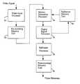
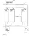
- FIG. 1is a block diagram illustration of a prior art video encoding circuit 10 .
- Encoding circuit 10includes a video input processor 12 , a motion estimation processor 14 , a digital signal processor 16 and a bitstream processor 18 .
- Processors 12 - 18are generally connected in series.
- Video input processor 12captures and processes a video signal, and transfers it to motion estimation processor 14 .
- Motion estimation processor 14analyzes the motion of the video signal, and transfers the video signal and its associated motion analysis to digital signal processor 16 .
- digital signal processor 16processes and compresses the video signal, and transfers the compressed data to bitstream processor 18 .
- Bitstream processor 18formats the compressed data and creates therefrom an encoded video bitstream, which is transferred out of encoding circuit 10 .
- bitstream processor 18transfers the encoded video bitstream, data word by data word, directly to an element external to encoding circuit 10 . Accordingly, each time such data word is ready, the encoded video data word is individually transferred to the external element. Transfer of the encoded video in such a fashion greatly increases the data traffic volume and creates communication bottlenecks in communication lines such as computer buses. Additionally, circuit 10 requires a dedicated storage/bus which is allocated on a full time basis, hence, magnifying these disturbances.
- encoding circuit 10is able to perform the encoding of video signals, only.
- moving picture compression applicationsinclude multiframe videos and their associated audio paths.
- the encoding circuit 10performs video compression and encoding, the multiplexing of compressed video, audio and user data streams are performed separately.
- Such an approachincreases the data traffic in the compression system and requires increased storage and processing bandwidth requirements, thereby greatly increasing the overall compression system complexity and cost.
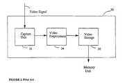
- FIG. 2is a block diagram of a prior art video input processor 30 , as may be typically included in encoding circuit 10 .
- Video input processor 30includes a video capture unit 32 , a video preprocessor 34 and a video storage 36 . The elements are generally connected in series.
- Video capture unit 32captures an input video signal and transfers it to video preprocessor 34 .
- Video preprocessor 34processes the video signal, including noise reduction, image enhancement, etc., and transfers the processed signal to the video storage 36 .
- Video storage 36buffers the video signal and transfers it to a memory unit (not shown) external to video input processor 30 .
- processor 30does not perform image resolution scaling. Accordingly, only original resolution pictures can be processed and encoded.
- processor 30does not perform statistical analysis of the video signal, since in order to perform comprehensive statistical analysis a video feedback from the storage is necessary, thus allowing interframe (picture to picture) analysis, and processor 30 is operable in “feed forward” manner, only. Accordingly, video input processor 30 can not detect developments in the video contents, such as scene change, flash, sudden motion, fade in/fade out etc.
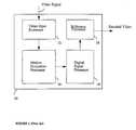
- FIG. 3is a block diagram illustration of a prior art video encoding circuit 50 , similar to encoding circuit 10 , however, connected to a plurality of external memory units.
- FIG. 3depicts circuit 50 connected to a pre-encoding memory unit 60 , a reference memory unit 62 and a post-encoding memory unit 64 , respectively.
- FIG. 4a chart depicting the flow of data within circuit 50 .
- Encoding circuit 50includes a video input processor 52 , a motion estimation processor 54 , a digital signal processor 56 and a bitstream processor 58 .
- Processors 54 to 58are generally connected in series.
- video encoding circuit 50operates under MPEG video/audio compression standards.
- reference to a current framerefers to a frame to be encoded.
- Reference to a reference framerefers to a frame that has already been encoded and reconstructed, preferably by digital signal processor 56 , and transferred to and stored in reference memory unit 62 .
- Reference framesare compared to current frames during the motion estimation task, which is generally performed by motion estimation processor 54 .
- Video input processor 52captures a video signal, which contains a current frame, or a plurality of current frames, and processes and transfers them to external pre-encoding memory unit 60 .
- External pre-encoding memory unit 60implements an input frame buffer (not shown) which accumulates and re-orders the frames according to the standard required for the MPEG compression scheme.
- External pre-encoding memory unit 60transfers the current frames to motion estimation processor 54 .
- External reference memory unit 62transfers the reference frames also to motion estimation processor 54 .
- Motion estimation processor 54reads and compares both sets of frames, analyzes the motion of the video signal, and transfers the motion analysis to digital signal processor 56 .
- Digital signal processor 56receives the current frames from the external pre-encoding memory 60 , and according to the motion analysis received from motion estimation processor 54 , processes and compresses the video signal. Digital signal processor 56 then transfers the compressed data to the bitstream processor 58 . Digital signal processor 56 further reconstructs the reference frame and stores it in reference memory 62 . Bitstream processor 58 encodes the compressed data and transfers an encoded video bitstream to external post-encoding memory unit 64 .
- encoding circuit 50has several disadvantages.
- one disadvantage of encoding circuit 50is that a plurality of separate memory units are needed to support its operations, thereby greatly increasing the cost and the complexity of any encoding system based on device 50 .
- encoding circuit 50has a plurality of separate memory interfaces. This increases the data traffic volume and the number of external connections of encoding circuit 50 , thereby greatly increasing the cost and the complexity of encoding circuit 50 .
- encoder circuit 50does not implement video and audio multiplexing, which is typically required in compression schemes.
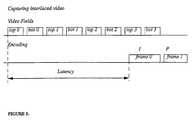
- FIG. 5a block diagram illustration of a typical interlaced formatted video in a normal encoding latency mode.
- the top linedepicts the video fields before encoding, while bottom line depicts compressed frames after encoding.
- Videois generally received in a progressive or interlaced form.
- Typical interlaced ratesare 60 fields/sec for NTSC standard and 50 fields/sec for PAL standard.
- Videois comprised of a plurality of fields, wherein each frame has a top and bottom field, referenced herein as top m and bot m.
- the video fields illustrated in FIG. 5are referenced top 0 and bot 0 , top 1 and bot 1 , etc. such that each pair of associated top and bot refers to a single frame.
- Iis defined as an I picture, which is the Intra frame or the first frame (frame 0 ) of the series of frames to be encoded
- Pis a P picture, which is the predictive frame (frame 1 ), and is referenced from frame 0 .
- the I/P ratiorefers to a distance between successive I/P frames in video sequence.
- the present inventionprovides a novel buffer architecture and latency reduction mechanism for buffering uncompressed/compressed information.
- the combination of the novel architecture, implemented with the latency reduction mechanismprovides for a proficient division of the encoding task effort and hence, a quicker through-put time.
- a single chip digital signal processing devicefor real time video/audio compression.
- the deviceincludes a plurality of processors, including a video input processor, a motion estimation processor, a digital signal processor, and a bitstream processor, wherein transfer of the signals within the device is done in a macroblock-by-macroblock manner, thus enabling pipeline macroblock-by-macroblock processing.
- the video input processorreceives, analyzes, scales and processes a digital signal.
- the motion estimation processorreceives the processed signal, produces a motion analysis therefrom, and transfers the motion analysis to the digital signal processor.
- the digital signal processoraccording to the motion analysis, compresses the processed signal and produces a compressed processed signal.
- a bitstream processorreceives and formats the compressed processed signal.
- the devicefurther includes a memory controller connected to the plurality of processors, wherein the memory controller controls data communication among the digital signal processor, the motion estimation processor, the video input processor and an external storage unit.
- the deviceincludes a multiplexing processor which multiplexes a plurality of digital signals and produces a multiplexed stream and a global controller which controls and schedules the video input processor, the motion estimation processor, the digital signal processor, the bitstream processor, the multiplexing processor and the memory controller.
- the motion estimation processor, the digital signal processor, the bitstream processor and the multiplexing processoroperate in parallel.
- the motion estimation processoroperates on macroblock a of frame I
- the digital signal processoroperates on macroblock b of frame I
- the bitstream processoroperates on macroblock c of frame I
- the multiplexing processoroperates on frame J, wherein a ⁇ b ⁇ c, and I ⁇ J.
- the video input processorincludes a capture unit, an input video storage, a video storage, a pre-encoding processor, a scaler, a video processor and a controller,
- the capture unitacquires a multiple frame video signal.
- the video storagebuffers the multiple frame video signal thereby allowing adjustment between an internal video rate and an external data communication rate.
- the pre-encoding processorreceives the multiple frame video signal from the capture unit and produces statistical analysis of the multiple frame video signal.
- the scalerreceives the multiple frame video signal from the pre-encoding processor and modifies picture resolution.
- the video processorprocesses the multiple video signal.
- the controllercontrols and schedules the capture unit, the pre-encoding processor, the scaler, the video processor and the video storage. Alternatively, the input storage buffers the video signal thereby adjusting between an external communication rate and internal video rate.
- the multiple frame video signalis acquired from either a video interface or a host interface.
- the video input processoroperates on frame K such that K ⁇ I ⁇ J.
- a video compression systemincluding a host interface, a memory unit and a digital signal processing device.
- the digital signal processing devicereceives a multiplicity of signals from the host interface and the memory unit and produces, in a pipeline macroblock-by-macroblock manner, a multiplexed encoded data stream.
- the multiplicity of signalsinclude either a video signal, an audio signal, or a user data stream.
- the systemadditionally includes a video interface which supplies a video signal to the digital signal processing device.
- the systemincludes a compressed data interface which receives the encoded signal from the digital signal processing device and an audio interface which transfers a digitized audio/user data signal to the digital signal processing device.
- a multiplexing processorwhich includes a first video storage, a second video storage, an audio/data storage, a processor and an output storage.
- the first video storagebuffers a compressed video bitstream, and transfers the compressed video bitstream to the external memory unit, thereby adjusting between internal video rate and external communication rate.
- the second video storagereads from the memory unit the compressed video bitstream, and buffers the compressed video bitstream, thereby adjusting between the external communication rate and the multiplexor processing rate rate.
- the audio/data storagebuffers the digitized audio/data signal and transfers the digitized audio/data signal to the processor, thereby adjusting between the external audio rate and the multiplexor processing rate.
- the processorconnected to the first and second video storage, the audio/data storage and the output storage, and which produces a multiplexed video/audio data stream.
- the output storagebuffers the multiplexed video/audio/data stream, thereby adjusting between multiplexed video/audio/data stream rate and external communication rate.
- the first video storageis connected to an external memory unit, wherein the first storage unit buffers the compressed video bitstream in a real time variable rate and transfers the compressed video bitstream in a burst to the memory unit.
- the second video storagetransfers the compressed video bitstream in a real time variable rate to the processor, and wherein the external memory unit transfers the compressed video bitstream in a burst to the second video storage.
- the audio/data storageis connected to an external audio source, wherein the audio/data storage transfers the digitized audio/data signal to the processor in a real time variable rate and the external audio source transfers the digitized audio/data signal in a burst to the audio/storage storage.
- the external memory unitacts as a temporary encoded video buffer, thereby accumulating compressed video when the processor is unable to accept the compressed video.
- the multiplexing processorinterfaces directly with a variety of communication devices, each the variety of communication devices having a different communication speed, such as a computer bus, and an asynchronous transmission line.
- the digital signal processing deviceincludes a plurality of processors, wherein the plurality of processors includes a digital signal processor, a bitstream processor, a motion estimation processor, and alternatively, a video input processor and a multiplexing processor.
- the digital signal processing devicefurther includes a memory controller connected to the plurality of processors, wherein the memory controller controls data communication among the digital signal processor, the motion estimation processor, the video input processor and an external storage unit.
- the devicefurther includes a global controller which controls and schedules the video input processor, the motion estimation processor, the digital signal processor, the bitstream processor, the multiplexing processor and the memory controller.
- a method for encodingincluding the steps of capturing a pipeline of a multiplicity of digitized video frames and encoding the multiple digitized video frames, one macroblock at a time.
- FIG. 1is a block diagram of a prior art video encoding circuit
- FIG. 2is a block diagram of a prior art video input processor
- FIG. 3is a block diagram of a prior art video encoding circuit linked to a plurality of external memory units
- FIG. 4is a flow chart of the data flow within the prior art circuit illustrated in FIG. 3 ;
- FIG. 5is a timing diagram of a typical video field pipeline in a normal encoding latency mode
- FIG. 6is a block diagram of a video encoding video/audio/data multiplexing device constructed and operative in accordance with a preferred embodiment of the invention
- FIG. 7is a block diagram of a motion estimation processor constructed and operative in accordance with a preferred embodiment of the invention.
- FIG. 8is a block diagram of a digital signal processor constructed and operative in accordance with a preferred embodiment of the invention.
- FIG. 9is a block diagram of a memory controller constructed and operative in accordance with a preferred embodiment of the invention.
- FIG. 10is a block diagram of a video input processor constructed and operative in accordance with a preferred embodiment of the invention.
- FIG. 11is a block diagram of a bitstream processor constructed and operative in accordance with a preferred embodiment of the invention.
- FIG. 12is a block diagram of a multiplexing processor constructed and operative in accordance with a preferred embodiment of the invention.
- FIG. 13is a block diagram of a global controller constructed and operative in accordance with a preferred embodiment of the invention.
- FIG. 14is a flow chart of the data flow within the device illustrated in FIG. 6 , provided in operative in accordance with a preferred embodiment of the invention.
- FIG. 15is a block diagram of an encoding latency mode provided in operative in accordance with a preferred embodiment of the invention.
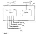
- FIG. 6a block diagram of a video encoding video/audio/data multiplexing device 100 , constructed and operative in accordance with a preferred embodiment of the invention.
- the present inventionovercomes the disadvantage of the prior art by providing a novel approach to video/audio compression and encoding, and, as per this approach, a novel encoding device structure which comprises a plurality of processors with a defined, optimized work division scheme.
- a sequence of compression commandsare instructions or a sequence of instructions, such as, removal of temporal redundancy, removal of spatial redundancy, and entropy redundancy of data, and the like.
- Device 100operates according to an optimized compression labor division, thus segmenting the compression tasks between the different processors and reducing, in comparison to prior art, the compression time. This is supported by a latency reduction mechanism, to be explained in detail hereinbelow.
- device 100is a massively parallel digital processor designed for the purposes of real-time video/audio compression and multiplexing, such as for MPEG encoding and the like.
- multiplexingrefers to the creation of a single synchronized stream of a plurality of unsynchronized audio and video streams.
- Device 100can be incorporated in a single chip and installed in digital camcorders, recordable digital video disk (DVD), game machines, desktop multimedia, video broadcast equipment, video authoring systems, video streaming and video conferencing equipment, security and surveillance systems, and the like.
- DVDrecordable digital video disk
- device 100efficiently performs video compression tasks such as removing temporal redundancy (i.e., motion between frames), spatial redundancy (within frame), and entropy redundancy of data.
- Device 100has a plurality of processors, each processor designed to perform a segment of the compression task, hence, achieving optimal performance of each such task.
- the number of processors, the architecture of each processor, and the task list per processorachieves the optimal tradeoff between device implementation cost and efficiency.
- Device 100is supported by an inventive latency reduction mechanism, to be described herein below.
- Device 100includes a video input processor 102 , a global controller 104 , a motion estimation processor 106 , a digital signal processor 108 , a memory controller 110 , a bitstream processor 112 and a multiplexing processor 114 .
- Device 100is preferably connectable to a video interface 120 , an external memory unit 122 , a compressed data interface 124 , a host interface 126 , and an audio interface 128 .
- video interface 120supplies a digital video signal
- audio interface 128supplies a digital audio signal.
- Host interface 126is typically connected to an external host (not shown) and acts as a user interface between device 100 and the user. Host interface 126 provides to device 100 microcodes, commands, data parameters and the like received from a user or a supervising system. Host interface 126 also provides information received from device 100 to the user. Host interface 126 provides access to the compressed data and is used to provide device 100 with uncompressed digitized video and/or audio and/or user data.
- device 100is operable either in a programming mode or an operational mode, and is capable of operating in both modes simultaneously.
- an external hosttransfers, via host interface 126 , microcodes, commands and data parameters to global controller 104 .
- Global controller 104transfers the microcodes, commands and data parameters to video input processor 102 , motion estimation processor 106 , digital signal processor 108 , memory controller 110 , bitstream processor 112 and multiplexing processor 114 .
- video input processor 102captures a motion video signal, via video interface 120 , from an external video source (not shown). In an alternative embodiment processor 102 captures a motion video signal, via host interface 126 .
- Video input processor 102then performs statistical analysis of the video signal, thereby detecting 3-2 pulled up sequences and developments in the video contents, such as scene change, sudden motion, fade in/fade out and the like. Video input processor 102 also performs resolution down-scaling thereby allowing, or enabling compression not only of the original resolution frames, but also reduced resolution frames (such as SIF, half D1 etc.). Additionally, video input processor 102 also pre-processes the video signal, such as spatial filtering, noise reduction, image enhancement and the like. Furthermore, video input processor 102 decreases the frame rate by decimating (dropping) frames thus allowing flexible rate control. Since device 100 is operable in “feed forward” manner, in order to perform the statistical analysis, a video feedback from the memory unit 122 is implementable. Such feedback allows interframe (picture to picture) analysis.
- Video input processor 102accumulates the scaled and processed video data and transfers the data in bursts to memory unit 122 , via memory controller 110 .
- Memory controller 110stores them in memory unit 122 .
- a data blockrepresents a macroblock, which is a sixteen by sixteen matrix of luminance pixels and two, four or eight, eight by eight matrices of chrominance pixels as defined by MPEG standards.
- reference to a reference framerefers to a frame that has already been encoded, reconstructed and stored in memory unit 112 , and which is compared to the current frame during the motion estimation performed by motion estimation processor 106 .
- the memory controller 110retrieves a current frame macroblock, and certain parts of the reference frames (referred hereto as search area) from memory unit 122 and loads them into motion estimation processor 106 .
- Motion estimation processor 106compares the current frame macroblock with the respective reference search area in accordance with a sequence of compression commands, thereby producing an estimation of the motion of the current frame macroblock. This estimation is used to remove temporal redundancy from the video signal.
- Motion estimation processor 106transfers the resulting motion estimation to global controller 104 .
- Motion estimation processor 106also transfers the current frame macroblock and the corresponding reference frames macroblocks to digital signal processor 108 .
- Digital signal processor 108performs series of macroblock processing operations intended to remove the spatial redundancy of the video signal, such as discrete cosine transform, macroblock type selection, quantization, rate control and the like. Digital signal processor 108 transfers the compressed data to the bitstream processor 112 . Digital signal processor 108 further processes the compressed frame, thus reconstructing the reference frames, and transfers the reconstructed reference frames to memory unit 122 via memory controller 110 , thereby overwriting some of the existing reference frames.
- Bitstream processor 112encodes the compressed video data into a standard MPEG format, in accordance with a sequence of known in the art encoding commands. Bitstream processor 112 then transfers the encoded video data stream to compressed data interface 124 . It will be noted that the compression data interface 124 is connectable to any data receptacle element, such as a storage unit, a transmission line, a computer bus or the like.
- Bitstream processor 112also transfers compressed video data stream to multiplexing processor 114 .
- multiplexing processor 114captures, via host interface 126 , digitized audio and/or user data from an external audio/data source (not shown). According to an alternative embodiment of the present invention, multiplexing processor 114 captures the digitized audio and/or user data via audio interface 128 .
- Multiplexing processor 114multiplexes the encoded video and the digitized audio and/or user data streams (as received from bitstream processor 112 ) and generates, according to a sequence of optimized multiplexing commands, MPEG standard format streams such as packetized elementary stream, program stream, transport stream and the like. Multiplexing processor 114 transfers the multiplexed video/audio/data streams to compressed data interface 124 . Multiplexing processor 114 also transfers the multiplexed video/audio/data streams to host interface 126 .
- Global controller 104controls and schedules the video input processor 102 , the motion estimation processor 106 , the digital signal processor 108 , the memory controller 110 , the bitstream processor 112 and the multiplexing processor 114 .
- the videois fed into device 100 in a horizontal raster scan manner, from the top-left pixel to the bottom-right pixel.
- Device 100processes a number of successive macroblocks of the same frame and a number of successive frames at the same time.
- the motion estimation processor 106processes macroblocks i through i+l of frame C
- the digital signal processor 108processes macroblocks j through j+m of frame C
- the bitstream processorprocesses macroblocks h through h+n of frame C
- the multiplexing processor 114processes frames A through A+B, wherein i+l> . . . >i>j+m> . . . >j>h+n> . . . >h, and C ⁇ A+B ⁇ . . . ⁇ A.
- memory unit 122is partitioned into many sub-areas, whereby the processors and controllers within device 100 are granted an access level which is selected from a list of access levels, such as read-write directly, read-write through the memory controller 110 , no access, and the like. It will be appreciated by those skilled in the art that such a structure provides a great level of flexibility whereby the amount of memory assigned to each processor is allocated dynamically in real time.
- FIG. 7is a block diagram of the motion estimation processor 106 , constructed and operative in accordance with a preferred embodiment of the present invention.
- Motion estimation processor 106includes a plurality of N search processors.
- FIG. 7depicts three search processors, 150 , 152 and 154 , respectively.
- motion estimation processor 106is operable either in a programming mode or an operational mode, and is capable of operating in both modes simultaneously.
- the programming mode, global controller 104provides control parameters and data parameters as well as microcodes and a sequence of compression commands to each search processor 150 , 152 and 154 , respectively.
- Each search processor 150 , 152 and 154is operable under different sets of control parameters, initialization parameters, microcodes, as well as under different sequences of compression commands.
- search processors 150 , 152 and 154are operable either in parallel or in a pipeline manner.
- search processor 150processes i th macroblock
- search processor 152processes the i+1 th macroblock
- search processor 154processes the i+N ⁇ 1 th macroblock, simultaneously.
- search processors 150 , 152 and 154process different portions of the same macroblock.
- search processors 150 , 152 and 154process different resolution frames.
- search processor 150processes a reduced resolution frame and produces a low resolution motion analysis
- search processor 152processes an original resolution frame and produces an original resolution motion analysis
- search processor 154processes an increased resolution frame and produces an increased resolution motion analysis.
- the current frame macroblock and the associated search areasare loaded into the applicable search processor i via memory controller 110 .
- the applicable search processor ithen performs a search procedure.
- the search processors 150 , 152 and 154can perform different types of searches, such as a full exhaustive search, telescopic search and the like, thereby producing the motion analysis.
- the global controller 104reads the motion analysis data from the search processors 150 , 152 and 154 .
- Motion estimation processor 106transfers the current frame macroblock and the reference frames macroblock to digital signal processor 108 .
- FIG. 8is a block diagram of digital signal processor 108 , constructed and operative in accordance with a preferred embodiment of the present invention.
- Digital signal processor 108includes a plurality of K processing units, a master controller 260 and a storage unit 270 .
- FIG. 8depicts 3 processing units, 250 , 252 and 254 , respectively.
- Digital signal processor 108is operable either in a programming mode or an operational mode, and is capable of operating in both modes simultaneously.
- global controller 104transfers data and control parameters, as well as microcodes and a sequence of compression commands, to master controller 260 and processing units 250 , 252 and 254 , respectively.
- the data transferred to each processing unitis independent from that transferred to each of the other processing units, and varies from processing unit to processing unit.
- Each processing unit 250 , 252 and 254is operable under a different set of control and data parameters, as well as under different sequences of compression commands.
- master controller 260 and processing units 250 , 252 and 254operate in parallel, thereby greatly increasing the computational power of the digital signal processor 108 .
- motion estimation processor 106transfers the current macroblock and its associated reference frames macroblock to processing units 250 , 252 and 254 .
- Global controller 104transfers the appropriate data parameters, such as the motion analysis and the like, to master controller 260 .
- Master controller 260performs processing procedures such as rate control, macroblock type selection, discrete cosine transform (DCT) type selection, and the like.
- processing proceduressuch as rate control, macroblock type selection, discrete cosine transform (DCT) type selection, and the like.
- DCTdiscrete cosine transform
- Processing units 250 , 252 and 254perform processing procedures on large data blocks, such as DCT, inverse DCT, quantization, inverse quantization, and the like. Preferably, each of processing units 250 , 252 and 254 operate independently, processing different data blocks and performing different sequences of optimized compression commands. Digital signal processor 108 produces a set of quantized DCT coefficients and reconstructed reference frame data.
- Each processing unitis capable of accessing the data blocks associated with each of the other processing units via storage unit 270 . Furthermore, processing units 250 , 252 , and 254 are operable in parallel. It will be appreciated by those skilled in the art that such a structure greatly enhances the efficiency of processing and data transfer in the digital signal processor 108 .
- processing units 250 , 252 and 254transfer the compressed coefficient blocks to the bitstream processor 112 .
- Master controller 260transfers the appropriate data parameters to the global controller 104 .
- Processing units 250 , 252 , 254further reconstruct the encoded frame (reference frame) and transfer the reconstructed reference frame to memory unit 122 via memory controller 110 , thus overwriting some of the existing reference frame.
- FIG. 9is a block diagram of memory controller 110 , constructed and operative in accordance with a preferred embodiment of the present invention.
- Memory controller 110includes an I/O port 300 and a controller 310 .
- Memory controller 110operates in either a programming mode or an operational mode, and is capable of operating in both modes simultaneously.
- global controller 104transfers data and control parameters to controller 310 .
- controller 104transfers a sequence of memory commands to controller 310 .
- Controller 310decodes the memory commands and sends the access instructions to I/O port 300 .
- I/O port 300transfers data to/from memory unit 122 to digital signal processor 108 , motion estimation processor 106 , video input processor 102 , and multiplexing processor 114 .
- the data transferred to each processoris independent from that transferred to each of the other processors, and varies from processor to processor.
- the data transferis comprised of an access stage and a data read/write stage.
- Memory controller 110 and the internal partition of memory unit 122are optimized to perform burst (large data block) transfers, thus reducing the number of memory access stages.
- the data transfer timecomprises mostly data read/write time, and thus, the total data transfer time is greatly reduced.
- Memory controller 110organizes data communication between the different processors of device 100 and external memory unit 122 , thereby implementing burst transfer. Thus each processor receives a continuous time segment for the data transfer and whereas all processors are serviced serially, one after the other, thereby greatly reducing the communication bandwidth requirements of device 100 .
- FIG. 10is a block diagram of video input processor 102 , constructed and operative in accordance with a preferred embodiment of the present invention.
- Video input processor 102includes a capture unit 350 , an input storage 355 , a pre-encoding processor 360 , a scaler 370 , a video processor 380 , a video storage 390 and a controller 395 .
- Capture unit 350receives, via video interface 120 , a digitized video signal from a digitized video source, (not shown).
- video input processor 102operates in either a programming mode and/or an operational mode, and is capable of operating in both modes simultaneously.
- global controller 104transfers data and control parameters, as well as a sequence of video commands, to controller 395 .
- capture unit 350acquires an input video signal. Capture unit 350 is synchronized to an external video source according to its associated format, its resolution, and the like. Capture unit 350 transfers the video synchronization signals to controller 395 . Controller 395 analyses the video synchronization signals and further transfers the video synchronization information to global controller 104 .
- Capture unit 350transfers the captured video data to pre-encoding processor 360 .
- Pre-encoding processor 360performs statistical analysis of the video signal and transfers this analysis to controller 395 .
- Controller 395produces scene analysis and transfers it to global controller 104 .
- the scene analysisdetects scene changes, sudden movement, fade in/fade out, 3-2 pull-up, and the like.
- Pre-encoding processor 360transfers the compressed video bitstream to scaler 370 .
- Controller 395schedules and controls units 350 , 360 , 370 , 380 and 390 . Controller 395 can further reduce the frame rate below original video source rate.
- Scaler 370receives the video signal and performs image resolution reduction. This reduces the amount of information required to transmit the compressed video signal, thereby greatly expanding the spectrum of applications of the device 100 . Scaler 370 transfers the scaled video signal to video processor 380 .
- Video processor 380performs a series of known in the art video processing procedures to enhance the scaled video signal.
- the video processing proceduresalso include color format conversion, noise reduction, image enhancement, and the like.
- Video processor 380transfers the processed video signal to video storage 390 .
- Video storage 390accumulates the processed video signal and provides the communication interface with memory controller 110 .
- Video storage 390adjusts the data rates of an external video signal to the internal data communication rates.
- Video input processor 102buffers the processed video signal in a real time variable rate, whereas the memory controller 110 transfers the video data block to memory unit 122 in a burst. This greatly reduces the communication bandwidth requirements, and makes the usage of the memory unit 122 more efficient.
- video input processor 102receives digitized video signal via the host interface 126 .
- the digitized video signalis transferred in bursts to the input storage 355 .
- Input storage 355buffers the video signal thereby adjusting from the external video rate (via host interface) to the internal data communication rate.
- Input storage 355further transfers the video signal to the capture unit 350 .
- FIG. 11is a block diagram of bitstream processor 112 , constructed and operative in accordance with a preferred embodiment of the invention.
- Bitstream processor 112includes a controller 450 , a storage unit 460 , an entropy encoder 470 and a bitstream formatter 480 .
- Bitstream processor 112operates in either a programming mode or an operational mode, and is capable of operating in both modes simultaneously.
- global controller 104transfers data and control parameters, as well as a sequence of encoding commands, to controller 450 .
- digital signal processor 108transfers compressed coefficient blocks to storage unit 460 .
- Global controller 104transfers motion analysis data to the controller 450 .
- Controller 450reads the compressed coefficients from the storage unit 460 .
- Controller 450further processes those compressed coefficients as well as the motion analysis data, and other data such as macroblock type, quantizer scale, closed caption and other VBI data and user data and the like, and transfers the processed data to entropy encoder 470 .
- Controller 450further controls and schedules storage unit 460 , entropy encoder 470 and bitstream formatter 480 .
- Entropy encoder 470performs a series of encoding procedures, such as run-length encoding, constant length encoding, variable length encoding, and the like, thereby producing encoded data. Entropy encoder 470 transfers the resultant encoded data to bitstream formatter 480 .
- Bitstream formatter 480receives the encoded data and, in accordance with standard requirements, such as MPEG, produces a compressed video data bitstream.
- entropy encoder 470 and bitstream formatter 480operate in parallel, thereby increasing the hardware resources utilization of bitstream processor 112 .
- FIG. 12is a block diagram of multiplexing processor 114 , constructed and operative in accordance with a preferred embodiment of the present invention.
- Multiplexing processor 114includes a processor 500 and multiple storages.
- the storages depicted in FIG. 12are a first video storage 510 , a second video storage 520 , an audio/data storage 530 and an output storage 540 .
- Multiplexing processor 114is operable in either a programming mode or an operational mode, and is capable of operating in both modes simultaneously.
- the global controller 104transfers data and control parameters, as well as a sequence of multiplexing commands, to processor 500 .
- bitstream processor 112transfers a compressed video bitstream to first video storage 510 .
- First video storage 510accumulates the compressed video bitstream and provides communication interface with memory controller 110 .
- First video storage 510adjusts the data rates of compressed video data to the external communication rates.
- Multiplexing processor 114buffers the compressed video bitstream in a real time variable rate, whereas, memory controller 110 transfers the compressed video bitstream in a burst to memory unit 122 . This greatly reduces the communication bandwidth requirements, and makes the usage of memory unit 122 more efficient.
- Second video storage 520reads the compressed video bitstream, via memory controller 110 , from memory unit 122 . Second video storage 520 transfers the compressed video data to processor 500 and adjusts the external communication rates to the data communication rates in multiplexing processor 114 .
- Second video storage 520transfers the compressed video to processor 500 in a real time variable rate, whereas, memory unit 122 transfers the compressed video in a burst, via memory controller 110 , to second video storage 520 . This greatly reduces the communication bandwidth requirements, and makes the usage of the memory unit 122 more efficient.
- this multiple level storage architectureallows dynamic allocation of a large temporary video buffer in external memory unit 122 .
- device 100is capable of accumulating large amounts of compressed video when an external receiving device is unable to accept the compressed video from the device 100 , or if an external audio source is unable to transfer the digitized audio to the device 100 . This greatly increases the tolerance of the device 100 .
- Audio/data storage 530reads the digitized audio and/or user data either via host interface 126 , or via audio interface 128 . Audio/data storage 530 transfers the digitized audio and/or user data to processor 500 . Processor 500 further accumulates video, audio and user data related parameters such as sizes, time microcodes and the like. Processor 500 additionally controls and schedules units 510 , 520 , 530 and 540 .
- Audio/data storage 530adjusts the external communication rates to the data communication rates in multiplexing processor 114 .
- Audio/data storage 530transfers the digitized audio and/or user data to processor 500 in a real time variable rate, whereas, the external audio source transfers the digitized audio and/or user data in a burst to audio/data storage 530 . This greatly reduces the communication bandwidth requirements.
- Processor 500multiplexes, in accordance with standard requirements, such as MPEG, the compressed video and digitized audio and/or user data and produces a multiplexed video/audio/data stream such as program stream, transport stream, and the like. Processor 500 transfers the multiplexed video/audio/data stream to output storage 540 .
- standard requirementssuch as MPEG
- Processor 500transfers the multiplexed video/audio/data stream to output storage 540 .
- Output storage 540accumulates the multiplexed video/audio/data stream and transfers it either to host interface 126 , or to compressed data interface 124 . Output storage 540 adjusts the data rates of the processor 500 to the external communication rates.
- Multiplexing processor 114buffers the multiplexed video/audio/data stream in a real time variable rate, whereas, either host interface 126 or the compressed data interface 124 can read the multiplexed video/audio/data stream in a burst or otherwise. This allows device 100 to interface directly with a variety of communication devices with different communication speed such as computer bus, asynchronous transmission line and the like, thereby simplifying the encoder system design and reducing the encoder system cost.
- FIG. 13is a block diagram of global controller 104 , constructed and operative in accordance with a preferred embodiment of the present invention.
- Global controller 104includes a storage unit 400 , a processor 410 and a data/control port 420 .
- global controller 104schedules, synchronizes and controls video input processor 102 , motion estimation processor 106 , digital signal processor 108 , memory controller 110 , bitstream processor 112 , and multiplexing processor 114 .
- Global controller 104also initializes and performs a variety of test procedures on video input processor 102 , motion estimation processor 106 , digital signal processor 108 , memory controller 110 , bitstream processor 112 , multiplexing processor 114 and external memory unit 122 .
- the global controller 104operates in either a programming mode or an operational mode, and is capable of operating in both modes simultaneously.
- an external hostloads data and control parameters, as well as sequences of control, video, compression, memory, encoding, and multiplexing commands, into processor 410 .
- Processor 410transfers the data, microcodes, and the control parameters, as well as the control command sequence, to storage unit 400 .
- Processor 410transfers the sequences of video, compression, memory, encoding and multiplexing commands to video input processor 102 , motion estimation processor 106 , digital signal processor 108 , memory controller 110 , bitstream processor 112 , and multiplexing processor 114 , respectively.
- the external hostloads a predetermined control pattern into processor 410 , thus instructing global controller 104 to perform according to the operational mode.
- processor 410receives video synchronization information from video input processor 102 , and acting upon such, synchronizes to an external video source.
- processor 410produces a series of control, data read and data write instructions, which are then transferred to data/control port 420 .
- data/control port 420provides control and synchronization signals to video input processor 102 , motion estimation processor 106 , digital signal processor 108 , memory controller 110 , bitstream processor 112 , and multiplexing processor 114 .
- data/control port 420reads the run-time data such as motion analysis, scene analysis, macroblock information, and the like, from video input processor 102 , motion estimation processor 106 , digital signal processor 108 , memory controller 110 , bitstream processor 112 , and multiplexing processor 114 .
- data/control port 420transfers the run-time data to video input processor 102 , motion estimation processor 106 , digital signal processor 108 , memory controller 110 , bitstream processor 112 , and multiplexing processor 114 .
- Storage unit 400is used as temporary storage for data, as well as control parameters. According to a sequence of control commands, in operational mode, processor 410 accesses storage unit 400 . Storage unit 400 thus accumulates data and control parameters received via host interface 126 , as well as accumulating status parameter/data received from controller 110 and processors 102 , 106 , 108 , 112 and 114 .
- device 100encodes in an assembly line fashion, e.g. each processor/controller performs a specialized processing task and transfers the signal onto the next processor/controller for processing.
- This encoding methodproduces an optimized division of labor and a quicker signal through-put time.
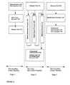
- FIG. 14a diagram depicting the multiple level pipeline organization implemented in device 100 .
- the multiple level pipeline flow of dataprogresses through three stages: from a pre-encoding frame pipeline stage (stage 1 ) to an encoding macroblock pipeline stage (stage 2 ) to a post-encoding frame pipeline stage (stage 3 ).
- video interface 120In the pre-encoding stage video interface 120 , host interface 126 , video input processor 102 , and memory unit 122 operate on frames A through A ⁇ B.
- memory unit 122 , motion estimation processor 106 , digital signal processor 108 , bitstream processor 112 , compressed data interface 124 and memory unit 122 , via bitstream processor 112operate on frame C.
- memory unit 122 , multiplexing processor 114 , compressed data interface 124 , and host interface 126operate on frames D through D ⁇ E, wherein, A ⁇ . . . ⁇ A ⁇ B ⁇ C ⁇ D ⁇ . . . ⁇ D ⁇ E. All three stages operate in parallel, thereby greatly increasing the performance of device 100 and enabling a low encoding latency.
- video interface 120In the pre-encoding stage (stage 1 ), video interface 120 , or host interface 126 , transfer a multiple frame A through A ⁇ B to video input processor 102 .
- the data as transferred from interface 120 or 126is as yet un-processed data, and still in raw data form.
- Video input processor 102receives the multiple frames A through A ⁇ B, processes them, and transfers the processed video signal to memory unit 122 .
- motion estimation processor 106receives the last step in stage 1 , which is also the first step in stage 2 .
- digital signal processor 108 and bitstream processor 112have immediate access to the processed video signal.
- memory unit 122transfers data to motion estimation processor 106 , digital signal processor 108 and bitstream processor 112 , respectively.
- Motion estimation processor 106receives and processes macroblocks i though i+l of the current frame C.
- Digital signal processor 108processes macroblocks j though j+m of the current frame C, and further reconstructs and transfers macroblocks j though j+m of the reference frame to memory unit 122 .
- Bitstream processor 112processes macroblocks h though h+n of the current frame C and transfers the encoded data to memory unit 122 and/or to compressed data interface 124 .
- motion processor 106digital processor 108 and bitstream processor 112 operate in parallel.
- multiplexing processor 114receives (from memory unit 122 ) encoded frames D through D ⁇ E and multiplexes the frames with a digitized audio/user data.
- the multiplexed data streamis transferred to compressed data interface 124 or to host interface 126 , which therefrom, is transferred to a receiving device external to device 100 .
- stage 1 , stage 2 and stage 3operate in parallel, and hence the data flow within device 100 is generally efficient and rapid.
- memory unit 122is a buffer which stores data between stage 1 and stage 2 , and between stage 2 and stage 3 . Hence, if any one stage operates quicker than any other stage, memory unit 122 stores the data until that appropriate stage is available for more data.
- device 100enables a flexible data flow rate, and is capable of regulating its flow to that of external units.
- FIG. 15a timing diagram illustration of pipeline encoding as per an encoding latency reduction mechanism 200 , known herein as encoder 200 .
- Encoder 200is operated and constructed in accordance with a preferred embodiment of the present invention.
- encoder 200is implemented in device 100 . Reference is also made in parallel to FIG. 6 .
- FIG. 15Elements illustrated in FIG. 15 which are similar to those elements illustrated in FIG. 5 are labeled with similarly referenced numerals, and will not be described further hereinbelow. Furthermore, for purposes of clarity in the understanding of FIG. 15 , a macroblock, as previously defined hereinabove, is a block of data.
- video framesare comprised of a number of lines, generally numbered 0 , 1 , 2 , 3 , etc.
- a videois transferred in either a progressive format or an interlaced format.
- even linesinclude 0 , 2 , 4 etc.
- odd linesinclude 1 , 3 , 5 etc. thus comprising even (top) and odd (bottom) fields.
- the videois transferred progressively, i.e. one after another, line 0 , line 1 , line 2 , line 3 , etc. are transferred.
- interlaced formattingrefers to the field by field formatting
- progressive formattingrefers to the frame by frame formatting
- FIG. 15illustrates both interlaced and progressive formatting.
- device 100encodes in a macroblock-by-macroblock manner. This method of encoding enables encoder 200 to start encoding after first few video lines are captured. If the video is interlaced formatted, the encoding process begins after the first field (i.e.: top 0 ) and a part of the second field associated with the first macroblock of an image (i.e.: bot 0 ), are recorded. Alternatively, if the video is progressively formatted, the encoding begins after the lines associated with the first macroblock of an image are recorded.
- the group of pictures (GOP) structureis IP and does not contain a B picture (not shown), where B pictures are Bi-directional pictures referencable from either picture I or picture P.
- encoder 200starts to output compressed video data with a latency of generally 5 ms (progressive video) or generally 20 ms (interlaced video).
- the resultant encoding latencyis dependent on the video standard used, i.e. either NTSC or PAL. This is in contrast to prior art encoders which latency is 100 ms through 150 ms.
- the present inventionprovides a video encoding video/audio/data multiplexing device which can be easily adapted to ISO/IEC 11172 (MPEG-1) standard as well as ISO/IEC 18313 (MEPG-2) standard as well as other compression standards such as H.320, H.261, H.263 as well as motion JPEG standard.
- MPEG-1MPEG-1
- ISO/IEC 18313MEPG-2
- other compression standardssuch as H.320, H.261, H.263 as well as motion JPEG standard.
Landscapes
- Engineering & Computer Science (AREA)
- Multimedia (AREA)
- Signal Processing (AREA)
- Computing Systems (AREA)
- Theoretical Computer Science (AREA)
- Compression Or Coding Systems Of Tv Signals (AREA)
Abstract
Description
Claims (7)
Priority Applications (1)
| Application Number | Priority Date | Filing Date | Title |
|---|---|---|---|
| US12/120,175US7751480B2 (en) | 1999-04-06 | 2008-05-13 | Video encoding and video/audio/data multiplexing device |
Applications Claiming Priority (5)
| Application Number | Priority Date | Filing Date | Title |
|---|---|---|---|
| IL12934599AIL129345A (en) | 1999-04-06 | 1999-04-06 | Video encoding and video/audio/data multiplexing device |
| IL129345 | 1999-04-06 | ||
| US09/543,904US6690726B1 (en) | 1999-04-06 | 2000-04-06 | Video encoding and video/audio/data multiplexing device |
| US10/744,531US7376185B2 (en) | 1999-04-06 | 2003-12-22 | Video encoding and video/audio/data multiplexing device |
| US12/120,175US7751480B2 (en) | 1999-04-06 | 2008-05-13 | Video encoding and video/audio/data multiplexing device |
Related Parent Applications (1)
| Application Number | Title | Priority Date | Filing Date |
|---|---|---|---|
| US10/744,531ContinuationUS7376185B2 (en) | 1999-04-06 | 2003-12-22 | Video encoding and video/audio/data multiplexing device |
Publications (2)
| Publication Number | Publication Date |
|---|---|
| US20080212681A1 US20080212681A1 (en) | 2008-09-04 |
| US7751480B2true US7751480B2 (en) | 2010-07-06 |
Family
ID=11072683
Family Applications (5)
| Application Number | Title | Priority Date | Filing Date |
|---|---|---|---|
| US09/543,904Expired - Fee RelatedUS6690726B1 (en) | 1999-04-06 | 2000-04-06 | Video encoding and video/audio/data multiplexing device |
| US10/282,736Expired - LifetimeUS7088771B2 (en) | 1999-04-06 | 2002-10-29 | Video encoding and video/audio/data multiplexing device |
| US10/744,531Expired - LifetimeUS7376185B2 (en) | 1999-04-06 | 2003-12-22 | Video encoding and video/audio/data multiplexing device |
| US11/452,480Expired - Fee RelatedUS9247263B2 (en) | 1999-04-06 | 2006-06-14 | Video encoding and video/audio/data multiplexing device |
| US12/120,175Expired - Fee RelatedUS7751480B2 (en) | 1999-04-06 | 2008-05-13 | Video encoding and video/audio/data multiplexing device |
Family Applications Before (4)
| Application Number | Title | Priority Date | Filing Date |
|---|---|---|---|
| US09/543,904Expired - Fee RelatedUS6690726B1 (en) | 1999-04-06 | 2000-04-06 | Video encoding and video/audio/data multiplexing device |
| US10/282,736Expired - LifetimeUS7088771B2 (en) | 1999-04-06 | 2002-10-29 | Video encoding and video/audio/data multiplexing device |
| US10/744,531Expired - LifetimeUS7376185B2 (en) | 1999-04-06 | 2003-12-22 | Video encoding and video/audio/data multiplexing device |
| US11/452,480Expired - Fee RelatedUS9247263B2 (en) | 1999-04-06 | 2006-06-14 | Video encoding and video/audio/data multiplexing device |
Country Status (5)
| Country | Link |
|---|---|
| US (5) | US6690726B1 (en) |
| EP (1) | EP1173930A4 (en) |
| AU (1) | AU3669000A (en) |
| IL (3) | IL129345A (en) |
| WO (1) | WO2000060759A1 (en) |
Cited By (13)
| Publication number | Priority date | Publication date | Assignee | Title |
|---|---|---|---|---|
| US20100061047A1 (en)* | 2001-02-28 | 2010-03-11 | Perego Richard E | Upgradable Memory System with Reconfigurable Interconnect |
| US8147339B1 (en) | 2007-12-15 | 2012-04-03 | Gaikai Inc. | Systems and methods of serving game video |
| US8412906B2 (en) | 2001-02-28 | 2013-04-02 | Rambus Inc. | Memory apparatus supporting multiple width configurations |
| US8506402B2 (en) | 2009-06-01 | 2013-08-13 | Sony Computer Entertainment America Llc | Game execution environments |
| US8560331B1 (en) | 2010-08-02 | 2013-10-15 | Sony Computer Entertainment America Llc | Audio acceleration |
| US8613673B2 (en) | 2008-12-15 | 2013-12-24 | Sony Computer Entertainment America Llc | Intelligent game loading |
| US8840476B2 (en) | 2008-12-15 | 2014-09-23 | Sony Computer Entertainment America Llc | Dual-mode program execution |
| US8888592B1 (en) | 2009-06-01 | 2014-11-18 | Sony Computer Entertainment America Llc | Voice overlay |
| US8926435B2 (en) | 2008-12-15 | 2015-01-06 | Sony Computer Entertainment America Llc | Dual-mode program execution |
| US8968087B1 (en) | 2009-06-01 | 2015-03-03 | Sony Computer Entertainment America Llc | Video game overlay |
| US9179156B2 (en) | 2011-11-10 | 2015-11-03 | Intel Corporation | Memory controller for video analytics and encoding |
| US9565314B2 (en) | 2012-09-27 | 2017-02-07 | Dolby Laboratories Licensing Corporation | Spatial multiplexing in a soundfield teleconferencing system |
| US9878240B2 (en) | 2010-09-13 | 2018-01-30 | Sony Interactive Entertainment America Llc | Add-on management methods |
Families Citing this family (71)
| Publication number | Priority date | Publication date | Assignee | Title |
|---|---|---|---|---|
| IL129345A (en)* | 1999-04-06 | 2004-05-12 | Broadcom Corp | Video encoding and video/audio/data multiplexing device |
| US8270479B2 (en)* | 1999-04-06 | 2012-09-18 | Broadcom Corporation | System and method for video and audio encoding on a single chip |
| US6643752B1 (en)* | 1999-12-09 | 2003-11-04 | Rambus Inc. | Transceiver with latency alignment circuitry |
| US7363422B2 (en) | 2000-01-05 | 2008-04-22 | Rambus Inc. | Configurable width buffered module |
| US7404032B2 (en)* | 2000-01-05 | 2008-07-22 | Rambus Inc. | Configurable width buffered module having switch elements |
| US20050010737A1 (en)* | 2000-01-05 | 2005-01-13 | Fred Ware | Configurable width buffered module having splitter elements |
| US7266634B2 (en)* | 2000-01-05 | 2007-09-04 | Rambus Inc. | Configurable width buffered module having flyby elements |
| US7356639B2 (en)* | 2000-01-05 | 2008-04-08 | Rambus Inc. | Configurable width buffered module having a bypass circuit |
| US7010642B2 (en)* | 2000-01-05 | 2006-03-07 | Rambus Inc. | System featuring a controller device and a memory module that includes an integrated circuit buffer device and a plurality of integrated circuit memory devices |
| US6502161B1 (en)* | 2000-01-05 | 2002-12-31 | Rambus Inc. | Memory system including a point-to-point linked memory subsystem |
| US7213075B2 (en)* | 2000-12-15 | 2007-05-01 | International Business Machines Corporation | Application server and streaming server streaming multimedia file in a client specific format |
| US6864896B2 (en)* | 2001-05-15 | 2005-03-08 | Rambus Inc. | Scalable unified memory architecture |
| DE10141130C1 (en)* | 2001-08-22 | 2003-04-03 | Sci Worx Gmbh | Digital image data stream coding and decoding method has several pre-processing and processing steps for coding, decoding and filtering effected in parallel |
| US7116712B2 (en)* | 2001-11-02 | 2006-10-03 | Koninklijke Philips Electronics, N.V. | Apparatus and method for parallel multimedia processing |
| SG105533A1 (en)* | 2002-01-31 | 2004-08-27 | St Microelectronics Asia | Memory transfer controller and method of transfer control of video line data and macroblock data |
| EP1333677A1 (en)* | 2002-01-31 | 2003-08-06 | BRITISH TELECOMMUNICATIONS public limited company | Video coding |
| US7878908B2 (en)* | 2002-11-14 | 2011-02-01 | Nintendo Co., Ltd. | Multiplexed secure video game play distribution |
| US20090118019A1 (en)* | 2002-12-10 | 2009-05-07 | Onlive, Inc. | System for streaming databases serving real-time applications used through streaming interactive video |
| US9077991B2 (en)* | 2002-12-10 | 2015-07-07 | Sony Computer Entertainment America Llc | System and method for utilizing forward error correction with video compression |
| US7684752B2 (en)* | 2002-12-10 | 2010-03-23 | Onlive, Inc. | Wireless network providing distributed video / data services |
| US9446305B2 (en) | 2002-12-10 | 2016-09-20 | Sony Interactive Entertainment America Llc | System and method for improving the graphics performance of hosted applications |
| US9192859B2 (en) | 2002-12-10 | 2015-11-24 | Sony Computer Entertainment America Llc | System and method for compressing video based on latency measurements and other feedback |
| US7558525B2 (en) | 2002-12-10 | 2009-07-07 | Onlive, Inc. | Mass storage repository for a wireless network |
| US8054880B2 (en)* | 2004-12-10 | 2011-11-08 | Tut Systems, Inc. | Parallel rate control for digital video encoder with multi-processor architecture and picture-based look-ahead window |
| US8964830B2 (en) | 2002-12-10 | 2015-02-24 | Ol2, Inc. | System and method for multi-stream video compression using multiple encoding formats |
| US8549574B2 (en) | 2002-12-10 | 2013-10-01 | Ol2, Inc. | Method of combining linear content and interactive content compressed together as streaming interactive video |
| US8949922B2 (en)* | 2002-12-10 | 2015-02-03 | Ol2, Inc. | System for collaborative conferencing using streaming interactive video |
| US8840475B2 (en)* | 2002-12-10 | 2014-09-23 | Ol2, Inc. | Method for user session transitioning among streaming interactive video servers |
| US10201760B2 (en)* | 2002-12-10 | 2019-02-12 | Sony Interactive Entertainment America Llc | System and method for compressing video based on detected intraframe motion |
| US7849491B2 (en)* | 2002-12-10 | 2010-12-07 | Onlive, Inc. | Apparatus and method for wireless video gaming |
| US9108107B2 (en)* | 2002-12-10 | 2015-08-18 | Sony Computer Entertainment America Llc | Hosting and broadcasting virtual events using streaming interactive video |
| US8526490B2 (en)* | 2002-12-10 | 2013-09-03 | Ol2, Inc. | System and method for video compression using feedback including data related to the successful receipt of video content |
| US9061207B2 (en) | 2002-12-10 | 2015-06-23 | Sony Computer Entertainment America Llc | Temporary decoder apparatus and method |
| US8366552B2 (en)* | 2002-12-10 | 2013-02-05 | Ol2, Inc. | System and method for multi-stream video compression |
| US9138644B2 (en)* | 2002-12-10 | 2015-09-22 | Sony Computer Entertainment America Llc | System and method for accelerated machine switching |
| US9314691B2 (en)* | 2002-12-10 | 2016-04-19 | Sony Computer Entertainment America Llc | System and method for compressing video frames or portions thereof based on feedback information from a client device |
| US8711923B2 (en) | 2002-12-10 | 2014-04-29 | Ol2, Inc. | System and method for selecting a video encoding format based on feedback data |
| US7590084B2 (en)* | 2003-02-14 | 2009-09-15 | Onlive, Inc. | Self-configuring, adaptive, three-dimensional, wireless network |
| US7593361B2 (en)* | 2003-02-14 | 2009-09-22 | Onlive, Inc. | Method of operation for a three-dimensional, wireless network |
| US7266147B2 (en) | 2003-03-31 | 2007-09-04 | Sharp Laboratories Of America, Inc. | Hypothetical reference decoder |
| US9015390B2 (en)* | 2003-04-25 | 2015-04-21 | Micron Technology, Inc. | Active memory data compression system and method |
| US20050063407A1 (en)* | 2003-09-23 | 2005-03-24 | Samsung Electronics Co., Ltd. | Apparatus and method for maintaining high-speed forwarding tables in a massively parallel router |
| US9292904B2 (en)* | 2004-01-16 | 2016-03-22 | Nvidia Corporation | Video image processing with parallel processing |
| US7760968B2 (en)* | 2004-01-16 | 2010-07-20 | Nvidia Corporation | Video image processing with processing time allocation |
| US7653265B2 (en)* | 2004-01-16 | 2010-01-26 | Nvidia Corporation | Video image processing with utility processing stage |
| CN1926885B (en)* | 2004-03-03 | 2013-03-13 | 卡莱汉系乐有限公司 | Video processing circuit and method of video processing |
| CA2593247A1 (en)* | 2005-01-10 | 2006-11-16 | Quartics, Inc. | Integrated architecture for the unified processing of visual media |
| US7464225B2 (en) | 2005-09-26 | 2008-12-09 | Rambus Inc. | Memory module including a plurality of integrated circuit memory devices and a plurality of buffer devices in a matrix topology |
| US7562271B2 (en) | 2005-09-26 | 2009-07-14 | Rambus Inc. | Memory system topologies including a buffer device and an integrated circuit memory device |
| US11328764B2 (en) | 2005-09-26 | 2022-05-10 | Rambus Inc. | Memory system topologies including a memory die stack |
| US8130841B2 (en)* | 2005-12-29 | 2012-03-06 | Harris Corporation | Method and apparatus for compression of a video signal |
| US20070226420A1 (en)* | 2006-03-22 | 2007-09-27 | Sung Chih-Ta S | Compression method and apparatus for a CPU |
| MX2008012710A (en)* | 2006-04-03 | 2008-11-27 | Lbp Mfg Inc | Thermally activatable insulating packaging. |
| US8952974B2 (en)* | 2006-04-20 | 2015-02-10 | Cisco Technology, Inc. | Latency reduction in a display device |
| US7710450B2 (en)* | 2006-04-20 | 2010-05-04 | Cisco Technology, Inc. | System and method for dynamic control of image capture in a video conference system |
| JPWO2007136088A1 (en)* | 2006-05-24 | 2009-10-01 | パナソニック株式会社 | Image encoding apparatus, image encoding method, and integrated circuit for image encoding |
| CN101345871B (en)* | 2007-03-08 | 2012-01-04 | 瑞昱半导体股份有限公司 | Method and device for video encoding and decoding |
| US9168457B2 (en) | 2010-09-14 | 2015-10-27 | Sony Computer Entertainment America Llc | System and method for retaining system state |
| BR122021007798B1 (en) | 2008-07-11 | 2021-10-26 | Fraunhofer-Gesellschaft Zur Forderung Der Angewandten Forschung E. V. | AUDIO ENCODER AND AUDIO DECODER |
| US8179460B2 (en)* | 2008-09-22 | 2012-05-15 | Aptina Imaging Corporation | System, method, and apparatus for variable rate pixel data transfer and storage |
| CN102422648A (en)* | 2009-02-24 | 2012-04-18 | 制造资源国际公司 | System for distributing multiple unique video/audio streams |
| US9762898B2 (en)* | 2010-02-01 | 2017-09-12 | Kelly Y Kishore | Method and system for parallelizing video compression |
| US9548061B2 (en) | 2011-11-30 | 2017-01-17 | Dolby International Ab | Audio encoder with parallel architecture |
| US9697491B2 (en) | 2013-12-19 | 2017-07-04 | Trapeze Software Ulc | System and method for analyzing performance data in a transit organization |
| US10319408B2 (en) | 2015-03-30 | 2019-06-11 | Manufacturing Resources International, Inc. | Monolithic display with separately controllable sections |
| US10922736B2 (en) | 2015-05-15 | 2021-02-16 | Manufacturing Resources International, Inc. | Smart electronic display for restaurants |
| US10269156B2 (en) | 2015-06-05 | 2019-04-23 | Manufacturing Resources International, Inc. | System and method for blending order confirmation over menu board background |
| US10319271B2 (en) | 2016-03-22 | 2019-06-11 | Manufacturing Resources International, Inc. | Cyclic redundancy check for electronic displays |
| CA3024512C (en) | 2016-05-31 | 2020-12-29 | Manufacturing Resources International, Inc. | Electronic display remote image verification system and method |
| WO2018031717A2 (en) | 2016-08-10 | 2018-02-15 | Manufacturing Resources International, Inc. | Dynamic dimming led backlight for lcd array |
| US11895362B2 (en) | 2021-10-29 | 2024-02-06 | Manufacturing Resources International, Inc. | Proof of play for images displayed at electronic displays |
Citations (15)
| Publication number | Priority date | Publication date | Assignee | Title |
|---|---|---|---|---|
| US5046080A (en) | 1989-05-30 | 1991-09-03 | Electronics And Telecommunications Research Institute | Video codec including pipelined processing elements |
| EP0743796A2 (en) | 1995-05-16 | 1996-11-20 | THOMSON multimedia | An easily expandable transport stream encoder |
| US5592399A (en) | 1993-05-26 | 1997-01-07 | Intel Corporation | Pipelined video encoder architecture |
| EP0784409A2 (en) | 1996-01-11 | 1997-07-16 | Sony Corporation | Video coding and multiplexing |
| US5731850A (en)* | 1995-06-07 | 1998-03-24 | Maturi; Gregory V. | Hybrid hierarchial/full-search MPEG encoder motion estimation |
| US5748240A (en)* | 1996-03-15 | 1998-05-05 | International Business Machines Corporation | Optimal array addressing control structure comprising an I-frame only video encoder and a frame difference unit which includes an address counter for addressing memory addresses |
| US5781788A (en)* | 1995-05-08 | 1998-07-14 | Avc Technology, Inc. | Full duplex single clip video codec |
| WO1999027487A1 (en) | 1997-11-25 | 1999-06-03 | Visiontech Ltd. | Video encoding device |
| US6011870A (en)* | 1997-07-18 | 2000-01-04 | Jeng; Fure-Ching | Multiple stage and low-complexity motion estimation for interframe video coding |
| US6157674A (en)* | 1996-03-21 | 2000-12-05 | Sony Corporation | Audio and video data transmitting apparatus, system, and method thereof |
| US6490250B1 (en)* | 1999-03-09 | 2002-12-03 | Conexant Systems, Inc. | Elementary stream multiplexer |
| US20030108105A1 (en)* | 1999-04-06 | 2003-06-12 | Amir Morad | System and method for video and audio encoding on a single chip |
| US6665872B1 (en)* | 1999-01-06 | 2003-12-16 | Sarnoff Corporation | Latency-based statistical multiplexing |
| US6690726B1 (en)* | 1999-04-06 | 2004-02-10 | Broadcom Corporation | Video encoding and video/audio/data multiplexing device |
| US20040161032A1 (en)* | 1999-04-06 | 2004-08-19 | Amir Morad | System and method for video and audio encoding on a single chip |
Family Cites Families (38)
| Publication number | Priority date | Publication date | Assignee | Title |
|---|---|---|---|---|
| US4665431A (en)* | 1982-06-24 | 1987-05-12 | Cooper J Carl | Apparatus and method for receiving audio signals transmitted as part of a television video signal |
| JP3321802B2 (en)* | 1990-06-28 | 2002-09-09 | キヤノン株式会社 | Digital signal processor |
| US5216502A (en)* | 1990-12-18 | 1993-06-01 | Barry Katz | Surveillance systems for automatically recording transactions |
| US5159447A (en)* | 1991-05-23 | 1992-10-27 | At&T Bell Laboratories | Buffer control for variable bit-rate channel |
| US5216503A (en)* | 1991-12-24 | 1993-06-01 | General Instrument Corporation | Statistical multiplexer for a multichannel image compression system |
| US5926208A (en)* | 1992-02-19 | 1999-07-20 | Noonen; Michael | Video compression and decompression arrangement having reconfigurable camera and low-bandwidth transmission capability |
| US5283646A (en)* | 1992-04-09 | 1994-02-01 | Picturetel Corporation | Quantizer control method and apparatus |
| DE69321558T2 (en)* | 1992-11-17 | 1999-04-22 | Matsushita Electric Industrial Co., Ltd., Kadoma, Osaka | Video and audio signal multiplexing and separating devices |
| US5448310A (en) | 1993-04-27 | 1995-09-05 | Array Microsystems, Inc. | Motion estimation coprocessor |
| US5598514A (en) | 1993-08-09 | 1997-01-28 | C-Cube Microsystems | Structure and method for a multistandard video encoder/decoder |
| US5872784A (en)* | 1993-10-20 | 1999-02-16 | Lsi Logic Corporation | High speed single chip digital video network apparatus |
| KR970010368B1 (en)* | 1994-01-18 | 1997-06-25 | 삼성전자 주식회사 | Cache line replace apparatus and method |
| US5864583A (en)* | 1994-04-22 | 1999-01-26 | Thomson Consumer Electronics, Inc. | Parameter sampling apparatus |
| US6330644B1 (en)* | 1994-10-27 | 2001-12-11 | Canon Kabushiki Kaisha | Signal processor with a plurality of kinds of processors and a shared memory accessed through a versatile control means |
| US5623311A (en) | 1994-10-28 | 1997-04-22 | Matsushita Electric Corporation Of America | MPEG video decoder having a high bandwidth memory |
| US5877812A (en)* | 1995-11-21 | 1999-03-02 | Imedia Corporation | Method and apparatus for increasing channel utilization for digital video transmission |
| DE19547707A1 (en) | 1995-12-20 | 1997-07-03 | Thomson Brandt Gmbh | Process, encoder and decoder for the transmission of hierarchical digital signals divided into several parts |
| US5825424A (en)* | 1996-06-19 | 1998-10-20 | Thomson Consumer Electronics, Inc. | MPEG system which decompresses and recompresses image data before storing image data in a memory and in accordance with a resolution of a display device |
| EP0817498B1 (en)* | 1996-06-28 | 2001-08-22 | STMicroelectronics S.r.l. | MPEG-2 decoding with a reduced RAM requisite by ADPCM recompression before storing MPEG-2 decompressed data optionally after a subsampling algorithm |
| US5793425A (en)* | 1996-09-13 | 1998-08-11 | Philips Electronics North America Corporation | Method and apparatus for dynamically controlling encoding parameters of multiple encoders in a multiplexed system |
| JPH10173674A (en) | 1996-12-13 | 1998-06-26 | Hitachi Ltd | Digital data transmission system |
| US6005621A (en)* | 1996-12-23 | 1999-12-21 | C-Cube Microsystems, Inc. | Multiple resolution video compression |
| US6038256A (en)* | 1996-12-31 | 2000-03-14 | C-Cube Microsystems Inc. | Statistical multiplexed video encoding using pre-encoding a priori statistics and a priori and a posteriori statistics |
| US6091455A (en)* | 1997-01-31 | 2000-07-18 | Hughes Electronics Corporation | Statistical multiplexer for recording video |
| US6026097A (en)* | 1997-03-13 | 2000-02-15 | 8 X 8, Inc. | Data processor having controlled scalable input data source and method thereof |
| KR100248427B1 (en)* | 1997-08-12 | 2000-03-15 | 이계철 | Apparatus and Method for Screen Division of MPEG Coded Image in Compressed Region |
| JPH1169330A (en)* | 1997-08-19 | 1999-03-09 | Fujitsu Ltd | Image communication device with answering machine function |
| JP3813320B2 (en)* | 1997-08-27 | 2006-08-23 | 株式会社東芝 | Motion vector detection method and apparatus |
| JP3185863B2 (en)* | 1997-09-22 | 2001-07-11 | 日本電気株式会社 | Data multiplexing method and apparatus |
| US6845107B1 (en)* | 1997-10-15 | 2005-01-18 | Sony Corporation | Video data multiplexer, video data multiplexing control method, method and apparatus for multiplexing encoded stream, and encoding method and apparatus |
| JPH11168727A (en) | 1997-12-02 | 1999-06-22 | Mitsubishi Electric Corp | Motion vector detection device |
| US6014708A (en)* | 1998-02-19 | 2000-01-11 | Alcatel | Adaptor and method for mapping a fast ethernet payload input signal to a synchronous payload envelope, as well as a clock selector for use therewith |
| US6259733B1 (en)* | 1998-06-16 | 2001-07-10 | General Instrument Corporation | Pre-processing of bit rate allocation in a multi-channel video encoder |
| JP3544524B2 (en)* | 1998-06-25 | 2004-07-21 | 松下電器産業株式会社 | Image processing device |
| US6816491B1 (en)* | 1998-11-04 | 2004-11-09 | Hitachi, Ltd. | Multiplexed audio data decoding apparatus and receiver apparatus |
| US6919892B1 (en)* | 2002-08-14 | 2005-07-19 | Avaworks, Incorporated | Photo realistic talking head creation system and method |
| US7027054B1 (en)* | 2002-08-14 | 2006-04-11 | Avaworks, Incorporated | Do-it-yourself photo realistic talking head creation system and method |
| US20080177994A1 (en)* | 2003-01-12 | 2008-07-24 | Yaron Mayer | System and method for improving the efficiency, comfort, and/or reliability in Operating Systems, such as for example Windows |
- 1999
- 1999-04-06ILIL12934599Apatent/IL129345A/ennot_activeIP Right Cessation
- 1999-04-06ILIL16038699Apatent/IL160386A/ennot_activeIP Right Cessation
- 2000
- 2000-04-06WOPCT/IL2000/000213patent/WO2000060759A1/enactiveApplication Filing
- 2000-04-06EPEP00915333Apatent/EP1173930A4/ennot_activeCeased
- 2000-04-06AUAU36690/00Apatent/AU3669000A/ennot_activeAbandoned
- 2000-04-06USUS09/543,904patent/US6690726B1/ennot_activeExpired - Fee Related
- 2002
- 2002-10-29USUS10/282,736patent/US7088771B2/ennot_activeExpired - Lifetime
- 2003
- 2003-12-22USUS10/744,531patent/US7376185B2/ennot_activeExpired - Lifetime
- 2004
- 2004-02-12ILIL16038604Apatent/IL160386A0/enunknown
- 2006
- 2006-06-14USUS11/452,480patent/US9247263B2/ennot_activeExpired - Fee Related
- 2008
- 2008-05-13USUS12/120,175patent/US7751480B2/ennot_activeExpired - Fee Related
Patent Citations (18)
| Publication number | Priority date | Publication date | Assignee | Title |
|---|---|---|---|---|
| US5046080A (en) | 1989-05-30 | 1991-09-03 | Electronics And Telecommunications Research Institute | Video codec including pipelined processing elements |
| US5592399A (en) | 1993-05-26 | 1997-01-07 | Intel Corporation | Pipelined video encoder architecture |
| US5781788A (en)* | 1995-05-08 | 1998-07-14 | Avc Technology, Inc. | Full duplex single clip video codec |
| EP0743796A2 (en) | 1995-05-16 | 1996-11-20 | THOMSON multimedia | An easily expandable transport stream encoder |
| US5731850A (en)* | 1995-06-07 | 1998-03-24 | Maturi; Gregory V. | Hybrid hierarchial/full-search MPEG encoder motion estimation |
| EP0784409A2 (en) | 1996-01-11 | 1997-07-16 | Sony Corporation | Video coding and multiplexing |
| US5748240A (en)* | 1996-03-15 | 1998-05-05 | International Business Machines Corporation | Optimal array addressing control structure comprising an I-frame only video encoder and a frame difference unit which includes an address counter for addressing memory addresses |
| US6157674A (en)* | 1996-03-21 | 2000-12-05 | Sony Corporation | Audio and video data transmitting apparatus, system, and method thereof |
| US6011870A (en)* | 1997-07-18 | 2000-01-04 | Jeng; Fure-Ching | Multiple stage and low-complexity motion estimation for interframe video coding |
| WO1999027487A1 (en) | 1997-11-25 | 1999-06-03 | Visiontech Ltd. | Video encoding device |
| US6665872B1 (en)* | 1999-01-06 | 2003-12-16 | Sarnoff Corporation | Latency-based statistical multiplexing |
| US6490250B1 (en)* | 1999-03-09 | 2002-12-03 | Conexant Systems, Inc. | Elementary stream multiplexer |
| US20030108105A1 (en)* | 1999-04-06 | 2003-06-12 | Amir Morad | System and method for video and audio encoding on a single chip |
| US6690726B1 (en)* | 1999-04-06 | 2004-02-10 | Broadcom Corporation | Video encoding and video/audio/data multiplexing device |
| US20040161032A1 (en)* | 1999-04-06 | 2004-08-19 | Amir Morad | System and method for video and audio encoding on a single chip |
| US7088771B2 (en)* | 1999-04-06 | 2006-08-08 | Broadcom Corporation | Video encoding and video/audio/data multiplexing device |
| US20060233261A1 (en)* | 1999-04-06 | 2006-10-19 | Leonid Yavits | Video encoding and video/audio/data multiplexing device |
| US7376185B2 (en)* | 1999-04-06 | 2008-05-20 | Leonid Yavits | Video encoding and video/audio/data multiplexing device |
Non-Patent Citations (1)
| Title |
|---|
| European Search Report corresponding to European Patent Application Serial No. 00915333.9-2223 dated Feb. 9, 2009. |
Cited By (22)
| Publication number | Priority date | Publication date | Assignee | Title |
|---|---|---|---|---|
| US20100061047A1 (en)* | 2001-02-28 | 2010-03-11 | Perego Richard E | Upgradable Memory System with Reconfigurable Interconnect |
| US8380927B2 (en)* | 2001-02-28 | 2013-02-19 | Rambus Inc. | Upgradable system with reconfigurable interconnect |
| US8412906B2 (en) | 2001-02-28 | 2013-04-02 | Rambus Inc. | Memory apparatus supporting multiple width configurations |
| US9824036B2 (en) | 2001-02-28 | 2017-11-21 | Rambus Inc. | Memory systems with multiple modules supporting simultaneous access responsive to common memory commands |
| US9257151B2 (en) | 2001-02-28 | 2016-02-09 | Rambus Inc. | Printed-circuit board supporting memory systems with multiple data-bus configurations |
| US8769234B2 (en) | 2001-02-28 | 2014-07-01 | Rambus Inc. | Memory modules and devices supporting configurable data widths |
| US8147339B1 (en) | 2007-12-15 | 2012-04-03 | Gaikai Inc. | Systems and methods of serving game video |
| US8613673B2 (en) | 2008-12-15 | 2013-12-24 | Sony Computer Entertainment America Llc | Intelligent game loading |
| US8926435B2 (en) | 2008-12-15 | 2015-01-06 | Sony Computer Entertainment America Llc | Dual-mode program execution |
| US8840476B2 (en) | 2008-12-15 | 2014-09-23 | Sony Computer Entertainment America Llc | Dual-mode program execution |
| US8888592B1 (en) | 2009-06-01 | 2014-11-18 | Sony Computer Entertainment America Llc | Voice overlay |
| US8968087B1 (en) | 2009-06-01 | 2015-03-03 | Sony Computer Entertainment America Llc | Video game overlay |
| US9203685B1 (en) | 2009-06-01 | 2015-12-01 | Sony Computer Entertainment America Llc | Qualified video delivery methods |
| US9584575B2 (en) | 2009-06-01 | 2017-02-28 | Sony Interactive Entertainment America Llc | Qualified video delivery |
| US9723319B1 (en) | 2009-06-01 | 2017-08-01 | Sony Interactive Entertainment America Llc | Differentiation for achieving buffered decoding and bufferless decoding |
| US8506402B2 (en) | 2009-06-01 | 2013-08-13 | Sony Computer Entertainment America Llc | Game execution environments |
| US8676591B1 (en) | 2010-08-02 | 2014-03-18 | Sony Computer Entertainment America Llc | Audio deceleration |
| US8560331B1 (en) | 2010-08-02 | 2013-10-15 | Sony Computer Entertainment America Llc | Audio acceleration |
| US9878240B2 (en) | 2010-09-13 | 2018-01-30 | Sony Interactive Entertainment America Llc | Add-on management methods |
| US10039978B2 (en) | 2010-09-13 | 2018-08-07 | Sony Interactive Entertainment America Llc | Add-on management systems |
| US9179156B2 (en) | 2011-11-10 | 2015-11-03 | Intel Corporation | Memory controller for video analytics and encoding |
| US9565314B2 (en) | 2012-09-27 | 2017-02-07 | Dolby Laboratories Licensing Corporation | Spatial multiplexing in a soundfield teleconferencing system |
Also Published As
| Publication number | Publication date |
|---|---|
| AU3669000A (en) | 2000-10-23 |
| US7088771B2 (en) | 2006-08-08 |
| EP1173930A1 (en) | 2002-01-23 |
| US20040136459A1 (en) | 2004-07-15 |
| IL129345A0 (en) | 2000-02-17 |
| IL160386A0 (en) | 2004-07-25 |
| EP1173930A4 (en) | 2009-03-11 |
| WO2000060759A1 (en) | 2000-10-12 |
| US6690726B1 (en) | 2004-02-10 |
| US20080212681A1 (en) | 2008-09-04 |
| IL129345A (en) | 2004-05-12 |
| US20030048847A1 (en) | 2003-03-13 |
| US20060233261A1 (en) | 2006-10-19 |
| US7376185B2 (en) | 2008-05-20 |
| IL160386A (en) | 2005-11-20 |
| US9247263B2 (en) | 2016-01-26 |
Similar Documents
| Publication | Publication Date | Title |
|---|---|---|
| US7751480B2 (en) | Video encoding and video/audio/data multiplexing device | |
| US20130039418A1 (en) | System and Method for Video and Audio Encoding on a Single Chip | |
| EP0843485B1 (en) | Video decoder with unified memory | |
| US5768537A (en) | Scalable MPEG2 compliant video encoder | |
| US5920353A (en) | Multi-standard decompression and/or compression device | |
| JP2001524766A (en) | Video coding device | |
| WO2006029195A1 (en) | Slab-based processing engine for motion video | |
| US7593580B2 (en) | Video encoding using parallel processors | |
| US7245821B2 (en) | Image processing using shared frame memory | |
| US5903311A (en) | Run level pair buffering for fast variable length decoder circuit | |
| EP0777387B1 (en) | Method and apparatus for encoding digital video signals | |
| US20090052551A1 (en) | Method and apparatus for coding moving image and imaging system | |
| EP1596603B1 (en) | Video encoder and method for detecting and encoding noise | |
| KR100395396B1 (en) | Method and apparatus for data compression of multi-channel moving pictures | |
| US5760847A (en) | Processing moving image data based on an arbitrarily designated frame | |
| US20040161032A1 (en) | System and method for video and audio encoding on a single chip | |
| EP0779744A2 (en) | Method and apparatus for decoding digital video signals | |
| JP3469866B2 (en) | Method for changing the bit rate of a data stream of an encoded video picture | |
| JPH08275152A (en) | Digital video signal decoding device | |
| JPH07273739A (en) | Digital signal coding and multiplexing device | |
| WO1998054908A1 (en) | Two pass decoding of mpeg b pictures for memory storage reduction | |
| KR20040020273A (en) | Apparatus and Method of Multi-Channel Video Encoding of Spatial Split Video |
Legal Events
| Date | Code | Title | Description |
|---|---|---|---|
| STCF | Information on status: patent grant | Free format text:PATENTED CASE | |
| FPAY | Fee payment | Year of fee payment:4 | |
| SULP | Surcharge for late payment | ||
| AS | Assignment | Owner name:BROADCOM CORPORATION, CALIFORNIA Free format text:ASSIGNMENT OF ASSIGNORS INTEREST;ASSIGNOR:VISIONTECH LTD.;REEL/FRAME:036685/0149 Effective date:20011031 Owner name:VISIONTECH LTD., ISRAEL Free format text:ASSIGNMENT OF ASSIGNORS INTEREST;ASSIGNORS:YAVITS, LEONID;MORAD, AMIR;REEL/FRAME:036685/0124 Effective date:20000629 | |
| AS | Assignment | Owner name:BANK OF AMERICA, N.A., AS COLLATERAL AGENT, NORTH CAROLINA Free format text:PATENT SECURITY AGREEMENT;ASSIGNOR:BROADCOM CORPORATION;REEL/FRAME:037806/0001 Effective date:20160201 Owner name:BANK OF AMERICA, N.A., AS COLLATERAL AGENT, NORTH Free format text:PATENT SECURITY AGREEMENT;ASSIGNOR:BROADCOM CORPORATION;REEL/FRAME:037806/0001 Effective date:20160201 | |
| AS | Assignment | Owner name:AVAGO TECHNOLOGIES GENERAL IP (SINGAPORE) PTE. LTD., SINGAPORE Free format text:ASSIGNMENT OF ASSIGNORS INTEREST;ASSIGNOR:BROADCOM CORPORATION;REEL/FRAME:041706/0001 Effective date:20170120 Owner name:AVAGO TECHNOLOGIES GENERAL IP (SINGAPORE) PTE. LTD Free format text:ASSIGNMENT OF ASSIGNORS INTEREST;ASSIGNOR:BROADCOM CORPORATION;REEL/FRAME:041706/0001 Effective date:20170120 | |
| AS | Assignment | Owner name:BROADCOM CORPORATION, CALIFORNIA Free format text:TERMINATION AND RELEASE OF SECURITY INTEREST IN PATENTS;ASSIGNOR:BANK OF AMERICA, N.A., AS COLLATERAL AGENT;REEL/FRAME:041712/0001 Effective date:20170119 | |
| MAFP | Maintenance fee payment | Free format text:PAYMENT OF MAINTENANCE FEE, 8TH YEAR, LARGE ENTITY (ORIGINAL EVENT CODE: M1552) Year of fee payment:8 | |
| AS | Assignment | Owner name:AVAGO TECHNOLOGIES INTERNATIONAL SALES PTE. LIMITE Free format text:MERGER;ASSIGNOR:AVAGO TECHNOLOGIES GENERAL IP (SINGAPORE) PTE. LTD.;REEL/FRAME:047196/0687 Effective date:20180509 | |
| AS | Assignment | Owner name:AVAGO TECHNOLOGIES INTERNATIONAL SALES PTE. LIMITE Free format text:CORRECTIVE ASSIGNMENT TO CORRECT THE EFFECTIVE DATE OF MERGER TO 9/5/2018 PREVIOUSLY RECORDED AT REEL: 047196 FRAME: 0687. ASSIGNOR(S) HEREBY CONFIRMS THE MERGER;ASSIGNOR:AVAGO TECHNOLOGIES GENERAL IP (SINGAPORE) PTE. LTD.;REEL/FRAME:047630/0344 Effective date:20180905 | |
| AS | Assignment | Owner name:AVAGO TECHNOLOGIES INTERNATIONAL SALES PTE. LIMITE Free format text:CORRECTIVE ASSIGNMENT TO CORRECT THE PROPERTY NUMBERS PREVIOUSLY RECORDED AT REEL: 47630 FRAME: 344. ASSIGNOR(S) HEREBY CONFIRMS THE ASSIGNMENT;ASSIGNOR:AVAGO TECHNOLOGIES GENERAL IP (SINGAPORE) PTE. LTD.;REEL/FRAME:048883/0267 Effective date:20180905 | |
| FEPP | Fee payment procedure | Free format text:MAINTENANCE FEE REMINDER MAILED (ORIGINAL EVENT CODE: REM.); ENTITY STATUS OF PATENT OWNER: LARGE ENTITY | |
| LAPS | Lapse for failure to pay maintenance fees | Free format text:PATENT EXPIRED FOR FAILURE TO PAY MAINTENANCE FEES (ORIGINAL EVENT CODE: EXP.); ENTITY STATUS OF PATENT OWNER: LARGE ENTITY | |
| STCH | Information on status: patent discontinuation | Free format text:PATENT EXPIRED DUE TO NONPAYMENT OF MAINTENANCE FEES UNDER 37 CFR 1.362 | |
| FP | Lapsed due to failure to pay maintenance fee | Effective date:20220706 |