US7751374B2 - WLAN TDM protocol - Google Patents
WLAN TDM protocolDownload PDFInfo
- Publication number
- US7751374B2 US7751374B2US11/311,890US31189005AUS7751374B2US 7751374 B2US7751374 B2US 7751374B2US 31189005 AUS31189005 AUS 31189005AUS 7751374 B2US7751374 B2US 7751374B2
- Authority
- US
- United States
- Prior art keywords
- wireless network
- network device
- ifs time
- ifs
- time
- Prior art date
- Legal status (The legal status is an assumption and is not a legal conclusion. Google has not performed a legal analysis and makes no representation as to the accuracy of the status listed.)
- Active, expires
Links
Images


Classifications
- H—ELECTRICITY
- H04—ELECTRIC COMMUNICATION TECHNIQUE
- H04W—WIRELESS COMMUNICATION NETWORKS
- H04W52/00—Power management, e.g. Transmission Power Control [TPC] or power classes
- H04W52/02—Power saving arrangements
- H04W52/0209—Power saving arrangements in terminal devices
- H04W52/0212—Power saving arrangements in terminal devices managed by the network, e.g. network or access point is leader and terminal is follower
- H04W52/0216—Power saving arrangements in terminal devices managed by the network, e.g. network or access point is leader and terminal is follower using a pre-established activity schedule, e.g. traffic indication frame
- H—ELECTRICITY
- H04—ELECTRIC COMMUNICATION TECHNIQUE
- H04W—WIRELESS COMMUNICATION NETWORKS
- H04W48/00—Access restriction; Network selection; Access point selection
- H04W48/08—Access restriction or access information delivery, e.g. discovery data delivery
- H04W48/10—Access restriction or access information delivery, e.g. discovery data delivery using broadcasted information
- H—ELECTRICITY
- H04—ELECTRIC COMMUNICATION TECHNIQUE
- H04W—WIRELESS COMMUNICATION NETWORKS
- H04W76/00—Connection management
- H04W76/20—Manipulation of established connections
- H—ELECTRICITY
- H04—ELECTRIC COMMUNICATION TECHNIQUE
- H04W—WIRELESS COMMUNICATION NETWORKS
- H04W84/00—Network topologies
- H04W84/02—Hierarchically pre-organised networks, e.g. paging networks, cellular networks, WLAN [Wireless Local Area Network] or WLL [Wireless Local Loop]
- H04W84/10—Small scale networks; Flat hierarchical networks
- H04W84/12—WLAN [Wireless Local Area Networks]
- Y—GENERAL TAGGING OF NEW TECHNOLOGICAL DEVELOPMENTS; GENERAL TAGGING OF CROSS-SECTIONAL TECHNOLOGIES SPANNING OVER SEVERAL SECTIONS OF THE IPC; TECHNICAL SUBJECTS COVERED BY FORMER USPC CROSS-REFERENCE ART COLLECTIONS [XRACs] AND DIGESTS
- Y02—TECHNOLOGIES OR APPLICATIONS FOR MITIGATION OR ADAPTATION AGAINST CLIMATE CHANGE
- Y02D—CLIMATE CHANGE MITIGATION TECHNOLOGIES IN INFORMATION AND COMMUNICATION TECHNOLOGIES [ICT], I.E. INFORMATION AND COMMUNICATION TECHNOLOGIES AIMING AT THE REDUCTION OF THEIR OWN ENERGY USE
- Y02D30/00—Reducing energy consumption in communication networks
- Y02D30/70—Reducing energy consumption in communication networks in wireless communication networks
Definitions
- the present inventionrelates to wireless networks, and more particularly to reducing power consumption of wireless network devices and improving network utilization.
- IEEE standards 802.11, 802.11a, 802.11b, 802.11g, 802.11h, 802.11n, 802.16, and 802.20which are hereby incorporated by reference in their entirety, define several different standards for configuring wireless networks and devices. According to these standards, wireless network devices may be operated in either an infrastructure mode or an ad-hoc mode.
- the wireless network devices or client stationscommunicate with each other through an access point.
- the wireless network devicescommunicate directly with each other and do not employ an access point.
- the term client station or mobile stationmay not necessarily mean that a wireless network device is actually mobile.
- a desktop computer that is not mobilemay incorporate a wireless network device and operate as a mobile station or client station.
- a wireless network that operates in the infrastructure modeincludes an access point (AP) and at least one client station that communicates with the AP.
- the wireless networkmay operate in an infrastructure mode. Since the client stations are often battery powered, it is important to minimize power consumption to preserve battery life. Therefore, some client stations implement a low power mode and an active, or “awake,” mode. During the active mode, the client station transmits and/or receives data. During the low power mode, the client station shuts down components and/or alters operation to conserve power. Usually, the client station is not able to transmit or receive data during the lower power mode.
- Wireless network devicesmay be implemented by a system on chip (SOC) circuit that includes a baseband processor (BBP), a medium access controller (MAC) device, a host interface, and one or more processors.
- a hostcommunicates with the wireless network device via the host interface.
- the SOC circuitmay include a radio frequency (RF) transceiver or the RF transceiver may be located externally.
- the host interfacemay include a peripheral component interface (PCI) although other types of interfaces may be used.
- PCIperipheral component interface
- a power management devicecontrols and selects different operating modes of the client stations. During operation, the power management device instructs some of the modules to transition to a low power mode to conserve power. Additional information may be found in U.S. patent application Ser. Nos. 10/650,887, filed on Aug. 28, 2003, Ser. No. 10/665,252, filed on Sep. 19, 2003, and Ser. No. 11/070,481, filed on Mar. 2, 2005, which are hereby incorporated by reference in their entirety.
- the first wireless network 10is illustrated in an infrastructure mode as defined by IEEE 802.11, and other future wireless standards.
- the first wireless network 10includes one or more client stations 12 and one or more access points (AP) 14 .
- the client station 12 and the AP 14transmit and receive wireless signals 16 .
- the AP 14is a node in a network 18 .
- the network 18may be a local area network (LAN), a wide area network (WAN), or another network configuration.
- the network 18may include other nodes such as a server 20 and may be connected to a distributed communications system 22 such as the Internet.
- the client station 12does not continuously transmit data to or receive data from the AP 14 . Therefore, the client station 12 implements a power savings mode when the client station 12 and the AP 14 do not have data to exchange. Data commonly remains intact in a network for a predetermined amount of time before it is dropped.
- the incorporated IEEE standardsprovide the opportunity for the client station 12 to inform the AP 14 when the client station 12 is entering a low power mode (and will not be capable of receiving data for a predetermined period). After notifying the AP 14 , the client station 12 transitions to the low power mode. During the low power period, the AP 14 buffers data that is intended to be transmitted to the client station 12 . Following the low power period, the client station 12 powers up and receives beacon transmissions from the AP 14 . If the beacon transmissions indicate that the AP 14 has data for the client station 12 , or the host processor of the client station 12 indicates it has data to transmit, the client station 12 remains active. Otherwise, the client station 12 enters the low power mode again.
- the AP 14attempts to transmit a beacon at a target beacon transmission time (TBTT). Before the AP 14 sends out a beacon transmission, the AP 14 determines whether other devices are currently transmitting data so that other devices are able to use the network.
- the client station 12transitions to the active mode prior to a beacon transmission to queue frames to transmit to the AP 14 in a buffer.
- the AP 14can exchange frames with one or more client stations 12 in a deterministic order.
- the AP 14 and the clients stations 12may exchange data according to Time Division Multiplexed (TDM) protocol.
- TDMTime Division Multiplexed
- the use of TDM protocolminimizes collisions that may occur when one or more of the client stations 12 attempt to transmit data to the AP 14 simultaneously.
- other wireless networks that are located near the first wireless network 10may not operate according to the above-described TDM protocol. As such, collisions may occur between the other wireless networks and the first wireless network 10 .
- each client station 12may wait for a random period prior to transmitting. This random period, or backoff period, reduces the likelihood that multiple client stations will attempt to transmit simultaneously.
- a wireless network that implements the random backoff periodhas improved collision avoidance over a wireless network that implements a pure TDM scheme when multiple networks exist in an overlapping region.
- random backoffbut does not guarantee collision avoidance.
- collision avoidanceis critical. For example, wireless networks that exchange multicast data typically do not include a positive acknowledgement feature. In other words, a transmitting station does not receive acknowledgement from a receiving station that the data was correctly received. Further, as a result of the random backoff periods, the time required for all stations in the wireless network to complete a set of frame exchanges is increased.
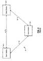
- a second wireless network 24operates in an ad-hoc mode.
- the second wireless network 24includes multiple client stations 26 - 1 , 26 - 2 , and 26 - 3 that transmit and receive wireless signals 28 .
- the client stations 26 - 1 , 26 - 2 , and 26 - 3collectively form a LAN and communicate directly with each other.
- the client stations 26 - 1 , 26 - 2 , and 26 - 3are not necessarily connected to another network.
- the client stations 26 - 1 , 26 - 2 , and 26 - 3do not continuously transmit data to and receive data from each other.
- the client stations 26implement a power savings mode when one of the client stations 26 - 1 does not have data to exchange with the other client stations 26 - 2 and 26 - 3 .
- the client stations 26 - 1 , 26 - 2 , and 26 - 3are not required to buffer data as performed in the AP.
- the client station 26 - 1transmits the beacon to the other client stations 26 - 2 and 26 - 3 .
- the client stations 26 - 2 and 26 - 3transition to the active mode prior to the beacon transmission.
- each client station 26transmits data in a deterministic order.
- the client stations 26may transmit data sequentially.
- a wireless network devicecomprises an RF transceiver that transmits and receives data packets and that periodically transmits or receives a beacon.
- a control modulecommunicates with the RF transceiver, determines a default interframe space (IFS) time based on the beacon, and that selects one of the default IFS time and a second IFS time that is less than or equal to the default IFS time based on a number of data packets received after the beacon.
- IFSinterframe space
- the beaconincludes data that is indicative of a transmission position m for the wireless network device.
- the control moduleselects the second IFS time when the RF transceiver receives m ⁇ 1 data packets.
- the control moduleselects the default IFS time when the RF transceiver has received fewer than m ⁇ 1 data packets.
- control moduleincludes an IFS timer that is reset when data packets are received.
- the RF transceivertransmits a data packet after one of the default IFS time and the second IFS time.
- a power management modulethat transitions the wireless network device between an active mode and an inactive mode. The power management module transitions the wireless network device to the active mode prior to a scheduled beacon time. The power management module transitions the wireless network device to the inactive mode after the RF transceiver transmits a data packet.
- a wireless network comprising the wireless network devicefurther comprises N ⁇ 1 other wireless network devices. The power management module transitions the wireless network device to the inactive mode after all of the N wireless network devices transmit a data packet.
- a wireless networkcomprises a plurality of the wireless network devices.
- the power management moduletransitions the wireless network devices to the inactive mode after an idle time on the network that is greater than a largest available IFS time.
- One of the wireless network devicesis a coordinator that periodically transmits the beacon to the plurality of wireless network devices.
- a wireless network devicecomprises transmitting and receiving means for transmitting and receiving data packets and for periodically transmitting or receiving a beacon.
- the wireless network devicecomprises control means for communicating with the transmitting and receiving means, for determining a default interframe space (IFS) time based on the beacon, and for selecting one of the default IFS time and a second IFS time that is less than or equal to the default IFS time based on a number of data packets received after the beacon.
- IFSinterframe space
- the beaconincludes data that is indicative of a transmission position m for the wireless network device.
- the control meansselects the second IFS time when the transmitting and receiving means receives m ⁇ 1 data packets.
- the control meansselects the default IFS time when the transmitting and receiving means has received fewer than m ⁇ 1 data packets.
- the control meansincludes timing means for monitoring IFS times. The timing means is reset when data packets are received and the transmitting and receiving means transmits a data packet after one of the default IFS time and the second IFS time.
- the wireless network devicefurther comprises power management means for transitioning the wireless network device between an active mode and an inactive mode.
- the power management meanstransitions the wireless network device to the active mode prior to a scheduled beacon time.
- the power management meanstransitions the wireless network device to the inactive mode after the transmitting and receiving means transmits a data packet.
- a wireless networkcomprising the wireless network device further comprises N ⁇ 1 other wireless network devices.
- the power management meanstransitions the wireless network device to the inactive mode after all of the N wireless network devices transmit a data packet.
- the power management meanstransitions the wireless network devices to the inactive mode after an idle time on the network that is greater than a largest available IFS time.
- One of the wireless network devicesis a coordinator that periodically transmits the beacon to the plurality of wireless network devices.
- a method for transmitting and receiving data with a wireless network devicecomprises at least one of transmitting and receiving data packets, at least one of periodically receiving and transmitting a beacon, determining a default interframe space (IFS) time based on the beacon, and selecting one of the default IFS time and a second IFS time that is less than or equal to the default IFS time based on a number of data packets received after the beacon.
- IFSinterframe space
- the step of selectingincludes selecting the second IFS time after receiving m ⁇ 1 data packets.
- the step of selectingincludes selecting the default IFS time when fewer than m ⁇ 1 data packets are received.
- An IFS timeris reset when data packets are received and a data packet is transmitted after one of the default IFS time or the second IFS time.
- a computer program executed by a processorcomprises at least one of transmitting and receiving data packets, at least one of periodically receiving and transmitting a beacon, determining a default interframe space (IFS) time based on the beacon, and selecting one of the default IFS time and a second IFS time that is less than or equal to the default IFS time based on a number of data packets received after the beacon.
- IFSinterframe space
- the beaconincludes data that is indicative of a transmission position m for a wireless network device.
- the step of selectingincludes selecting the second IFS time after receiving m ⁇ 1 data packets.
- the step of selectingincludes selecting the default IFS time when fewer than m ⁇ 1 data packets are received.
- An IFS timeris reset when data packets are received and a data packet is transmitted after one of the default IFS time or the second IFS time.
- the wireless network deviceis transitioned between an active mode and an inactive mode.
- the step of transitioningincludes transitioning the wireless network device to the active mode prior to a scheduled beacon time.
- the step of transitioningincludes transitioning the wireless network device to the inactive mode after transmitting a data packet.
- the wireless network deviceis transitioned to the inactive mode after N wireless network devices transmit a data packet, wherein N is a number of wireless network devices in a wireless network including the wireless network device.
- the wireless network deviceis transitioned to the inactive mode after an idle time on a wireless network including the wireless network device that is greater than a largest available IFS time.
- the beaconis transmitted to a plurality of wireless network devices.
- a first wireless network device in a wireless networkthat includes a plurality of wireless network devices comprises an RF transceiver that transmits and receives data packets and that periodically transmits or receives a beacon.
- a control modulecommunicates with the RF transceiver, determines a transmission position m and a default IFS time based on the beacon, selects a second IFS time when the RF transceiver receives a data packet from a second wireless network device having a transmission position m ⁇ 1, and selects the default IFS time when the RF transceiver does not receive a data packet from the second wireless network device.
- the second IFS timeis less than or equal to the default IFS time.
- the RF transceivertransmits a data packet after one of the default IFS time or the second IFS time.
- a power management moduletransitions the wireless network device between an active mode and an inactive mode. The power management module transitions the wireless network device to the active mode prior to a scheduled beacon time. The power management module transitions the wireless network device to the inactive mode after the RF transceiver transmits the data packet.
- a wireless networkcomprising the wireless network device further comprises N ⁇ 1 wireless network devices.
- the power management moduletransitions the wireless network device to the inactive mode after all of the N wireless network devices transmit a data packet.
- a coordinator deviceperiodically transmits the beacon to the RF transceiver.
- a first wireless network device in a wireless networkthat includes a plurality of wireless network devices comprises transmitting and receiving means for transmitting and receiving data packets and for periodically transmitting or receiving a beacon, and control means for communicating with the transmitting and receiving means, for determining a transmission position m and a default IFS time based on the beacon, for selecting a second IFS time when the transmitting and receiving means receives a data packet from a second wireless network device having a transmission position m ⁇ 1, and for selecting the default IFS time when the transmitting and receiving means does not receive a data packet from the second wireless network device.
- the second IFS timeis less than or equal to the default IFS time.
- the RF transceivertransmits a data packet after one of the default IFS time or the second IFS time.
- the wireless network devicefurther comprises power management means for transitioning the wireless network device between an active mode and an inactive mode.
- the power management meanstransitions the wireless network device to the active mode prior to a scheduled beacon time.
- the power management meanstransitions the wireless network device to the inactive mode after the RF transceiver transmits the data packet.
- a wireless networkcomprising the wireless network device of further comprises N ⁇ 1 wireless network devices.
- the power management meanstransitions the wireless network device to the inactive mode after all of the N wireless network devices transmit a data packet.
- a method for transmitting and receiving data with a first wireless network device in a wireless network that includes a plurality of wireless network devicescomprises transmitting and receiving data packets, periodically transmitting or receiving a beacon, determining a transmission position m and a default IFS time based on the beacon, selecting a second IFS time when the first wireless network device receives a data packet from a second wireless network device having a transmission position m ⁇ 1, and selecting the default IFS time when the first wireless network device does not receive a data packet from the second wireless network device.
- the second IFS timeis less than or equal to the default IFS time.
- a data packetis transmitted after one of the default IFS time or the second IFS time.
- the first wireless network deviceis transitioned between an active mode and an inactive mode.
- the step of transitioningincludes transitioning the first wireless network device to the active mode prior to a scheduled beacon time.
- the step of transitioningincludes transitioning the first wireless network device to the inactive mode after the first wireless network device transmits the data packet.
- the wireless networkincludes N wireless network devices.
- the first wireless network deviceis transitioned to the inactive mode after all of the N wireless network devices transmit a data packet.
- a computer program executed by a processorcomprises transmitting and receiving data packets, periodically transmitting or receiving a beacon, determining a transmission position m and a default IFS time based on the beacon, selecting a second IFS time when a first wireless network device receives a data packet from a second wireless network device having a transmission position m ⁇ 1, and selecting the default IFS time when the first wireless network device does not receive a data packet from the second wireless network device.
- the second IFS timeis less than or equal to the default IFS time.
- a data packetis transmitted after one of the default IFS time or the second IFS time.
- the first wireless network deviceis transitioned between an active mode and an inactive mode.
- the step of transitioningincludes transitioning the first wireless network device to the active mode prior to a scheduled beacon time.
- the step of transitioningincludes transitioning the first wireless network device to the inactive mode after the first wireless network device transmits the data packet.
- a wireless network device in a wireless networkthat includes a plurality of wireless network devices comprises an RF transceiver that transmits and receives data packets and that periodically transmits or receives a beacon.
- a control modulecommunicates with the RF transceiver, determines a group identifier and a station identifier based on the beacon, and selects one of a default IFS time and a second IFS time based on a data packet received.
- the control moduleselects one of the default IFS time and the second IFS time based on the data packet received and at least one of the group identifier and/or the station identifier.
- the second IFS timeis less than or equal to the default IFS time.
- the control moduledetermines a group identifier x and a station identifier y based on the beacon.
- the control moduleselects the second IFS time when the data packet is received from a second wireless network device having a group identifier x- 1 and a station identifier y.
- the control moduleselects the second IFS time when the data packet is received from a second wireless network device having a group identifier less than x and a station identifier y.
- the control moduleselects the default IFS time when the data packet is received from a second wireless network device having a group identifier x and a station identifier other than y.
- a group IFS timeis based on the group identifier
- a delta IFS timeis based on the station identifier
- the default IFS timeis a sum of the group IFS time and the delta IFS time.
- the devicetransmits a data packet after one of the default IFS time or the second IFS time.
- a power management modulethat transitions the wireless network device between an active mode and an inactive mode. The power management module transitions the wireless network device to the active mode prior to a scheduled beacon time. The power management module transitions the wireless network device to the inactive mode after the RF transceiver transmits the data packet.
- a coordinator deviceperiodically transmits the beacon to the RF transceiver.
- a wireless network device in a wireless networkcomprises transmitting and receiving means for transmitting and receiving data packets and for periodically transmitting or receiving a beacon and control means for communicating with the transmitting and receiving means, for determining a group identifier and a station identifier based on the beacon, and for selecting one of a default IFS time and a second IFS time based on a data packet received.
- control meansselects one of the default IFS time and the second IFS time based on the data packet received and at least one of the group identifier and/or the station identifier.
- the second IFS timeis less than or equal to the default IFS time.
- the control meansdetermines a group identifier x and a station identifier y based on the beacon.
- the control meansselects the second IFS time when the data packet is received from a second wireless network device having a group identifier x ⁇ 1and a station identifier y.
- the control meansselects the second IFS time when the data packet is received from a second wireless network device having a group identifier less than x and a station identifier y.
- the control meansselects the default IFS time when the data packet is received from a second wireless network device having a group identifier x and a station identifier other than y.
- a group IFS timeis based on the group identifier
- a delta IFS timeis based on the station identifier
- the default IFS timeis a sum of the group IFS time and the delta IFS time.
- the devicetransmits a data packet after one of the default IFS time or the second IFS time.
- the wireless network devicefurther comprises power management means for transitioning the wireless network device between an active mode and an inactive mode.
- the power management meanstransitions the wireless network device to the active mode prior to a scheduled beacon time.
- the power management meanstransitions the wireless network device to the inactive mode after the device transmits the data packet.
- a method for transmitting and receiving data with a first wireless network device in a wireless network that includes a plurality of wireless network devicescomprises transmitting and receiving data packets, periodically transmitting or receiving a beacon, determining a group identifier and a station identifier based on the beacon, and selecting one of a default IFS time and a second IFS time based on a data packet received.
- the step of selectingincludes selecting one of the default IFS time and the second IFS time based on the data packet received and at least one of the group identifier and/or the station identifier.
- the second IFS timeis less than or equal to the default IFS time.
- a group identifier x and a station identifier yare determined based on the beacon.
- the step of selectingincludes selecting the second IFS time when the data packet is received from a second wireless network device having a group identifier x ⁇ 1 and a station identifier y.
- the step of selectingincludes selecting the second IFS time when the data packet is received from a second wireless network device having a group identifier less than x and a station identifier y.
- the step of selectingincludes selecting the default IFS time when the data packet is received from a second wireless network device having a group identifier x and a station identifier other than y.
- a group IFS timeis based on the group identifier
- a delta IFS timeis based on the station identifier
- the default IFS timeis a sum of the group IFS time and the delta IFS time.
- a data packetis transmitted after one of the default IFS time or the second IFS time.
- the first wireless network deviceis transitioned between an active mode and an inactive mode.
- the step of transitioningincludes transitioning the first wireless network device to the active mode prior to a scheduled beacon time.
- the step of transitioningincludes transitioning the wireless network device to the inactive mode after transmitting the data packet.
- a computer program executed by a processorcomprises transmitting and receiving data packets, periodically transmitting or receiving a beacon, determining a group identifier and a station identifier based on the beacon, and selecting one of a default IFS time and a second IFS time based on a data packet received.
- the step of selectingincludes selecting one of the default IFS time and the second IFS time based on the data packet received and at least one of the group identifier and/or the station identifier.
- the second IFS timeis less than or equal to the default IFS time.
- a group identifier x and a station identifier yare determined based on the beacon.
- the step of selectingincludes selecting the second IFS time when the data packet is received from a wireless network device having a group identifier x ⁇ 1 and a station identifier y.
- the step of selectingincludes selecting the second IFS time when the data packet is received from a wireless network device having a group identifier less than x and a station identifier y.
- the step of selectingincludes selecting the default IFS time when the data packet is received from a wireless network device having a group identifier x and a station identifier other than y.
- a group IFS timeis based on the group identifier
- a delta IFS timeis based on the station identifier
- the default IFS timeis a sum of the group IFS time and the delta IFS time.
- a data packetis transmitted after one of the default IFS time or the second IFS time.
- a wireless network deviceis transitioned between an active mode and an inactive mode.
- the step of transitioningincludes transitioning the wireless network device to the active mode prior to a scheduled beacon time.
- the step of transitioningincludes transitioning the wireless network device to the inactive mode after transmitting the data packet.
- the systems and methods described aboveare implemented by a computer program executed by one or more processors.
- the computer programcan reside on a computer readable medium such as but not limited to memory, non-volatile data storage and/or other suitable tangible storage mediums.
- FIG. 1is a functional block diagram of a wireless network that is configured in an infrastructure mode and that includes one or more client stations and an access point (AP) according to the prior art;
- APaccess point
- FIG. 2is a functional block diagram of a wireless network that is configured in an ad-hoc mode and that includes multiple client stations according to the prior art;
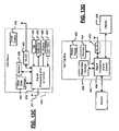
- FIG. 3is a functional block diagram of a wireless gaming network that is configured in an infrastructure mode wireless local area network (LAN) according to the present invention
- FIG. 4is a functional block diagram of an AP for a console in a wireless gaming network that includes an SOC and a radio frequency (RF) transceiver according to the present invention
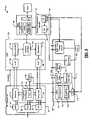
- FIG. 5is a functional block diagram of a wireless network device according to the present invention.
- FIG. 6is a timing diagram that illustrates client station TDM protocol delta times in a wireless LAN according to the prior art
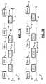
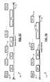
- FIG. 7Ais a timing diagram that illustrates client station IFS times in a wireless LAN according to a first implementation of the present invention
- FIG. 7Bis a timing diagram that illustrates client station IFS times in a wireless LAN according to a first implementation of the present invention
- FIG. 7Cis a timing diagram that illustrates client station IFS times in a wireless LAN according to a first implementation of the present invention
- FIG. 7Dis a timing diagram that illustrates client station IFS times in a wireless LAN according to a first implementation of the present invention
- FIG. 8is a flowchart that illustrates steps performed by a wireless network device to select client station IFS times according to a first implementation of the present invention.
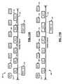
- FIG. 9Ais a timing diagram that illustrates client station IFS times in a wireless LAN according to a second implementation of the present invention.
- FIG. 9Bis a timing diagram that illustrates client station IFS times in a wireless LAN according to a second implementation of the present invention.
- FIG. 9Cis a timing diagram that illustrates client station IFS times in a wireless LAN according to a second implementation of the present invention.
- FIG. 10is a flowchart that illustrates steps performed by a wireless network device to select client station IFS times according to a second implementation of the present invention
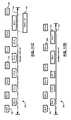
- FIG. 11Ais a timing diagram that illustrates client station IFS times in a wireless LAN according to a third implementation of the present invention.
- FIG. 11Bis a timing diagram that illustrates client station IFS times in a wireless LAN according to a third implementation of the present invention.
- FIG. 11Cis a timing diagram that illustrates client station IFS times in a wireless LAN according to a third implementation of the present invention.
- FIG. 11Dis a timing diagram that illustrates client station IFS times in a wireless LAN according to a third implementation of the present invention.
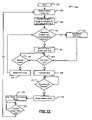
- FIG. 12is a flowchart that illustrates steps performed by a wireless network device to select client station IFS times according to a third implementation of the present invention
- FIG. 13Ais a functional block diagram of a high definition television
- FIG. 13Bis a functional block diagram of a vehicle control system
- FIG. 13Cis a functional block diagram of a cellular phone.
- FIG. 13Dis a functional block diagram of a set top box.
- module and/or devicerefers to an application specific integrated circuit (ASIC), an electronic circuit, a processor (shared, dedicated, or group) and memory that execute one or more software or firmware programs, a combinational logic circuit, and/or other suitable components that provide the described functionality.
- ASICapplication specific integrated circuit
- processorshared, dedicated, or group
- memorythat execute one or more software or firmware programs, a combinational logic circuit, and/or other suitable components that provide the described functionality.
- An inter-frame space (IFS) timeis a minimum time that a station waits after the communication medium becomes free prior to transmitting data.
- IFSinter-frame space
- the wireless protocol according to the present inventionallows stations to use shorter and/or constant IFS times with no random backoff periods. By preventing collisions while eliminating the need for random backoff periods and by maintaining short IFS times for every station, the average awake time and the power consumption of all of the stations is reduced.
- a wireless network operating in either an infrastructure mode or an ad hoc modemay implement the wireless protocol as described herein.
- most or all of the stationsneed to transmit data regularly, for example, at each beacon interval.
- This type of networkis a wireless console gaming application. Since most or all of the stations transmit frames to one or more other stations during each beacon interval, a master station determines a station access sequence after each beacon transmission. The master station can vary the station access sequence by randomizing or rotating the order following each beacon transmission. The IFS time for each station is dependent partly upon the access sequence and partly upon frames previously received in a particular beacon period. In this manner, a given client station will transmit data according to a first IFS time during a first beacon interval, and according to a second or different IFS time during a second beacon interval.
- all client stationstransmit frames to every other client station during each beacon interval.
- the IFS times of each client stationdictate a client access sequence for a given beacon interval.
- the client station access sequenceis varied by randomizing or rotating the IFS times among the client stations following each beacon transmission. In this manner, a given client station will transmit data according to a first IFS time during a first beacon interval, and according to a second IFS time during a second beacon interval.
- a wireless gaming network 30includes a host gaming device 32 and one or more client gaming devices 34 .
- the client gaming devices 34include wireless local area network (WLAN) hardware and operate as client stations in an infrastructure mode network.
- the host gaming device 32also includes wireless LAN hardware and operates as an access point (AP) in the wireless gaming network.
- the wireless gaming networkallows for greater mobility of the client gaming devices 34 and conserves operating power by reducing the overall duration of the active mode.
- the host gaming device 32 and the client gaming devices 34may be a game console and wireless input devices, respectively, or any other suitable implementation of an AP and one or more wireless client stations.
- the wireless gaming network 30excludes the host gaming device 32 and operates in an ad hoc mode.
- an exemplary AP 14 for a host gaming device 32includes a system on chip (SOC) 34 .
- the SOC 34includes a baseband processor (BBP) 42 , a media access control (MAC) device 44 , and other SOC components, identified collectively at 46 , including interfaces, memory, and/or processors.
- a radio frequency (RF) transceiver 48along with the BBP 42 communicates with the MAC device 44 .
- the RF transceiver 48transmits/receives data to/from client stations in the wireless LAN. Since the AP 14 may have data that is intended for the client stations during the low power mode, the MAC device 44 includes a buffer 50 .
- the MAC device 44stores data that is intended for the client stations in the buffer 50 until the client stations enter the active mode.
- the AP 14may be a node in a network 18 that includes other nodes such as a server 20 and may be connected to a distributed communications system 22 such as the Internet.
- Each client gaming device 34includes an exemplary wireless network device 60 as shown in FIG. 5 .
- the wireless network device 60according to some implementations of the present invention is shown to include an RF transceiver module 62 , a baseband processor module 64 , a power and clock module 66 , a MAC module 68 , and a power management module 70 .
- the RF transceiver 62includes a receiver 72 and a transmitter 74 . While not shown, the network device 60 can also include a processor and other standard components.
- a frequency synthesizer 76includes a phase locked loop (PLL) 78 that receives a first reference frequency from an oscillator such as a crystal oscillator 80 .
- the frequency synthesizer 76also contains a voltage controlled oscillator (VCO) 82 , which provides an adjustable frequency output based on an input signal thereto.
- VCOvoltage controlled oscillator
- the frequency synthesizer 76generates RF and IF output signals for the receiver and transmitter 72 and 74 , respectively.
- a low noise amplifier (LNA) 84receives signals from an antenna (not shown), amplifies the signals and outputs them to the receiver 72 .
- LNAlow noise amplifier
- PApower amplifier
- the BBP 64includes an analog to digital converter (ADC) 88 that receives signals from the receiver 72 .
- the ADC 88communicates with a demodulator 90 , which demodulates the signals.
- An output of the demodulator 90communicates with an external interface 92 , which communicates with the MAC 68 .
- the MAC 68sends signals to the external interface 92 , which are modulated by a modulator 94 and output to a digital to analog converter (DAC) 96 .
- the DAC 96outputs signals to the transmitter 74 .
- the BBP 64also may include a PLL (not shown).
- the ADC 88 and the DAC 96may be located on the RF transceiver 62 .
- the power and clock module 66includes a multi-level voltage source 98 that receives an input voltage such as VDD and a mode signal and outputs two or more voltage levels.
- the power and clock module 66also includes a low power (LP) oscillator 100 .
- the power management module 70along with the MAC module 68 and processor (not shown) selects an operating mode of the wireless network device 60 .
- the operating modesinclude active and inactive (i.e. low power) modes, although additional modes may be provided.
- the power management module 70may also be located in the MAC module 68 or the power and clock module 66 .
- An optional calibration module 102 that is associated with the power management module 70is optionally used to calibrate the duration of the inactive mode.
- the calibration module 102receives an output of the LP oscillator 100 and a PLL 104 and calibrates a value of a counter 106 that is used to calculate the duration of the inactive mode.
- the calibrationcan be performed periodically, on an event basis, randomly, before transitioning to the inactive mode and/or on any other suitable basis.
- the calibration module 102may be omitted from the wireless network device 60 .
- the power and clock module 66further includes current and voltage bias circuits 108 and 110 , respectively, that provide current and/or voltage biases to various circuits and/or modules (connections not shown) in the wireless network device 60 .
- the current bias circuit 108may include one or more off-chip calibration resistors (not shown) and the voltage bias circuit may include one or more on-chip resistors (not shown).
- a band gap voltage reference 112may be used to bias the current bias circuit 108 .
- a clock data recovery (CDR) module 114performs clock recovery and includes analog and digital modules 116 and 118 , respectively, or only digital modules.
- An output of the phase lock loop (PLL) 104is coupled to the CDR module 114 .
- an exemplary TDM timing diagram 120is illustrated.
- One or more client stationsenter the active mode prior to the transmission of a beacon signal 122 .
- the APtransmits the beacon signal 122 .
- the client stationsIn the ad hoc mode, however, one of the client stations transmits the beacon signal.
- the client stationsattempt to transmit data according to assigned delay times following the reception of the beacon and during an awake interval 124 that is defined by the beacon signal 122 .
- Delay, or delta, times for each client stationcan be varied each beacon interval.
- the default delay timesmay be carried in the beacon signal 122 .
- the station access sequence for the client stationsvaries with each beacon interval.
- the client stationswait the delay time after the transmission medium becomes free before transmitting data.
- the device that receives the data packetmay transmit an acknowledgment data packet if the destination of the packet is a single receiver.
- a first client stationwaits a first delta time 1 as illustrated at 126 .
- Second, third, and nth client stationsbegin waiting second, third, . . . , and nth delta times, respectively. Since the delta time 1 is the shortest, it terminates first.
- the first client stationtransmits a data packet as illustrated at 128 . While the first client station transmits a data packet at 128 , the remaining client stations are still waiting for their corresponding delta times. In other words, the transmission of the first client station at 128 occurs while the remaining client stations are still waiting for their respective delta times to expire. Therefore, the second client station waits the second delta time 2 (the next shortest delta time) as illustrated at 130 . The second client station then transmits a data packet as illustrated at 132 .
- the third client stationwaits the third delta time 3 as illustrated at 134 , and then transmits a data packet as illustrated at 136 .
- the nth client stationwaits the nth delta time n as illustrated at 138 , and then transmits a data packet as illustrated at 139 .
- the delta times of each stationcan be varied.
- the nth client stationmay operate according to the first delta time 1
- the first client stationmay operate according to the third delta time 3 .
- the delta times of the remaining client stationsare varied.
- the delta times, and therefore the station access sequencemay be varied sequentially, randomly, or in any other suitable manner.
- the client stationstransition to, the low power mode after all client stations complete transmission as illustrated by the termination of the awake interval 124 .
- each client stationremains awake in order to receive all data packets from other client stations in the network.
- each client stationtransitions to the low power mode immediately after transmitting a data packet.
- wireless input devices operating as client stationsmay transition to the low power mode immediately after transmitting data to the console (AP). Since the station access sequence varies following each beacon interval, the first, second, third, and nth client stations consume approximately the same average power over time.
- a timing diagram 140illustrates a first implementation of the present invention.
- Each client stationis assigned a default unique IFS time 1 , 2 , 3 , . . . , n as opposed to the unique delta times described with respect to FIG. 6 .
- the unique IFS timescause the stations to transmit in the order of ascending IFS, similar to the effect of the delta times described in FIG. 6 .
- the IFS timesmeasure a time since the transmission media becomes free rather than a fixed time since the beacon transmission 122 . In this manner, each client station waits a unique IFS time after the beacon transmission 122 and/or after a previous client station completes transmission.
- the client stationsfollow one or more rules during each beacon interval to determine whether to wait the assigned default IFS time or a shorter alternative IFS time. In one implementation, if a client station receives an expected number of data packets of a particular type (i.e. all preceding client stations have transmitted), then that client station waits the alternative IFS time.
- each client stationhas a single data packet to transmit to all other client stations.
- a client stationmay have more than one data packet type to transmit during a beacon interval. For example, a client gaming device may transmit a control data packet to a host gaming device, and then transmit a gaming data packet to all other client gaming devices. Therefore, subsequent client gaming devices would expect to receive the gaming data packet, but not the control data packet.
- the client stationwaits the IFS time 1 .
- the IFS time 1is the default IFS time of the first client station as illustrated at 142 .
- the first client stationwaits the first IFS time 1 and transmits a data packet as illustrated at 144 .
- the second client stationis second in the station access sequence according to the IFS time 2 , and therefore only expects to receive the data packet from the first client station (i.e. one data packet of an expected type) prior to transmitting. If the second client station receives the data packet from the first client station, the second client station waits the IFS time 1 as illustrated at 146 , and transmits a data packet as illustrated at 148 .
- the third client stationis third in the station access sequence, and therefore expects to receive two data packets prior to transmitting. If the third client station receives the data packets from the first and second client stations, the third client station waits the IFS time 1 as illustrated at 150 and transmits a data packet as illustrated at 152 . The nth client station operates analogously and waits the IFS time 1 as illustrated at 154 before transmitting a data packet as illustrated at 156 . In subsequent beacon intervals, the IFS times are varied as described above, but the clients stations continue to follow the one or more rules for alternative IFS times.
- the awake interval 124is significantly reduced if most or all client stations transmit and receive properly.
- the timing diagram 140illustrates operation of the client stations when one client station does not receive a data packet from a preceding client station.
- the first client stationtransmits a data packet after IFS time 1 as illustrated at 158 .
- the second client stationdoes not properly receive the data packet from the first client station.
- the second client stationmay not receive the data packet due to noise or other network problems. Therefore, the second client station waits the IFS time 2 as illustrated at 160 prior to transmitting a data packet as illustrated at 162 .
- the third and nth client stationsproperly receive all preceding data packets and wait the IFS time 1 prior to transmitting as illustrated at 164 and 166 , respectively.
- the timing diagram 140illustrates operation of the client stations when client stations 3 and above do not receive a data packet from a preceding client station.
- the first client stationtransmits a data packet after the IFS time 1 as illustrated at 170 .
- the second client stationreceives the data packet and transmits after the IFS time 1 as illustrated at 172 .
- the third and nth client stationsdo not receive the data packet from the second client station. For example, noise may corrupt the transmission from the second client station. Therefore, the third and nth client stations are not able to use IFS time 1 , and use the default IFS times 3 , and n, respectively.
- the second client stationmay be absent from the network and/or fail to transmit altogether as shown in FIG. 7D .
- the first client stationtransmits a data packet after the IFS time 1 as illustrated at 174 .
- the second client stationdoes not transmit a data packet. Therefore, the third client station waits the default IFS time 3 after the first client station completes transmission as illustrated at 176 .
- the third client stationtransmits a data packet after the IFS time 3 as illustrated at 178 .
- the nth client stationwaits the default IFS time n after an (n ⁇ 1)th client station completes transmission as illustrated at 180 , and then transmits a data packet as illustrated at 182 .
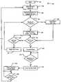
- a first IFS time selection method 184begins in step 186 .
- the client stationsenter the active mode prior to receiving a beacon transmission.
- the client stationsreceive the beacon signal.
- the beacon signalincludes data that determines the default IFS times of the client stations.
- the beacon signalmay also indicate a slot m within the station access sequence for each client station.
- the beacon signalmay include a single value that indicates both the default IFS time and the slot m of each client station.
- the beacon signalmay include a timer synchronization function (TSF) value that indicates the default IFS time and/or the slot m of the client station.
- TSFtimer synchronization function
- a client stationdetermines whether it received m ⁇ 1 data packets of the correct type. If true, the method 184 continues to step 194 . If false, the method 184 continues to step 196 .
- the client stationwaits an alternative IFS time that is less than or equal to the default IFS time.
- the client stationwaits the default IFS time.
- step 198the client station determines whether the IFS time of step 194 or step 196 is up. If true, the method 184 continues to step 200 . If false, the method 184 continues to step 201 . In step 201 , the client station determines whether the transmission medium is free. If true, the method 184 returns to step 198 . If false, the method 184 continues to step 202 . In step 202 , the client station resets the IFS timer, and the method 184 returns to step 192 . In other words, the client station continues to wait the IFS time for as long as the transmission medium is free. If the client station detects activity on the transmission medium, the IFS timer resets.
- step 200the client station transmits a data packet.
- step 203the method 184 determines whether the client station has received data packets from all the other client stations in the wireless network, and/or whether the beacon interval will expire soon. If true, the method 184 continues to step 206 . If false, the method 184 returns to step 203 until all packets are received. In other words, if all stations have completed transmission and/or the beacon interval is to expire soon, the method 184 continues to step 206 . Otherwise, the method 184 returns to step 203 and the station waits while each client station attempts to transmit in this manner.
- step 206the client station enters the inactive mode.
- step 207the method 184 starts an inactive mode timer.
- step 208the method 184 determines whether the inactive mode timer is up. If true, the method 184 repeats for subsequent beacon intervals and returns to step 188 . If false, the method 184 returns to step 208 .
- the timing diagram 210illustrates a second implementation of the present invention. If a client station receives a data packet of a particular type from the immediately preceding client station, the client station waits an alternative IFS time before transmitting data. If the client station does not receive the particular data packet from the immediately preceding client station, the client station waits the default IFS time before transmitting data.
- each client station in the networkmaintains a table of MAC addresses for all other client stations in the network. In other words, each client station is able to identify the data packet received from an immediately preceding client station based on its MAC address. Additionally, each data packet includes information that identifies its order in the station access sequence. In this manner, a receiving client station is able to determine if a particular data packet was transmitted by the immediately preceding client station.
- the client stationwaits the IFS time 1 . If all client stations receive the data packet from the corresponding immediately preceding client station, all client stations wait the IFS time 1 as shown previously in FIG. 7A .
- the timing diagram 210illustrates operation of the client stations when one client station does not receive a data packet from an immediately preceding client station.
- the first client stationtransmits a data packet after IFS time 1 as illustrated at 212 .
- the second client stationdoes not properly receive the data packet from the first client station. Therefore, the second client station waits the IFS time 2 prior to transmitting a data packet as illustrated at 214 .
- the third client stationproperly receives the data packet from the second client station, and the nth client station properly receives the data packet from an (n ⁇ 1)th station. Therefore, the third client station and the nth client station wait the IFS time 1 before transmitting data.
- the timing diagram 210illustrates operation of the client stations when all subsequent client stations do not receive a data packet from a preceding client station.
- the first client stationtransmits a data packet after IFS time 1 as illustrated at 216 .
- the second, third, and nth client stationsdo not receive the data packet from the first client station.
- the second client stationwaits the IFS time 2 prior to transmitting a data packet as illustrated at 218 .
- the third and nth client stationsdo not need to receive the data packet from the first client station in order to use the IFS time 1 . If the third client station properly receives the data packet from the second client station, the third client station uses IFS time 1 . Likewise, if the nth client station receives the data packet from the (n ⁇ 1)th client station, the nth client station uses IFS time 1 .
- the timing diagram 210illustrates operation of the client stations when one client station stops transmitting or disconnects from the wireless network.
- the first client stationtransmits a data packet after IFS time 1 as illustrated at 220 .
- the second client stationdoes not transmit. Therefore, the third client station transmits a data packet after waiting the IFS time 3 as illustrated at 222 . If the nth client station properly receives the data packet from the (n ⁇ 1)th client station, the nth client station uses IFS time 1 .
- subsequent client stationswill use the alternative IFS time if the immediately preceding client station transmitted a particular data packet.
- collisionmay occur.
- the second client stationwill transmit a data packet after IFS time 2 .
- the third client stationwill attempt to transmit a data packet after IFS time 1 .
- the first client stationwill wait until the second client station completes transmission, and also attempt to transmit a data packet after IFS time 1 , resulting in collision. Therefore, although the implementation described in FIGS. 9A through 9C provides significant improvement in a noise-free environment, it can be seen that operation in certain environments is undesirable.
- a second IFS time selection method 224begins in step 226 .
- the client stationstransition to the active mode prior to receiving a beacon transmission.
- the client stationsreceive the beacon signal.
- the beacon signalincludes data that determines the default IFS times of the client stations, which determines the slot in the station access sequence for each client station.
- a client stationdetermines whether it received a data packet from the client station in slot m ⁇ 1. If true, the method 224 continues to step 234 . If false, the method 224 continues to step 236 .
- the client stationwaits an alternative IFS time that is shorter than the default IFS time.
- the client stationwaits the default IFS time.
- step 238the client station determines whether the IFS time of step 234 or step 236 is up. If true, the method 224 continues to step 240 . If false, the method 224 continues to step 241 . In step 241 , the client station determines whether the transmission medium is free. If true, the method 224 returns to step 238 . If false, the method 224 continues to step 242 . In step 242 , the client station resets the IFS timer, and the method 224 returns to step 232 .
- step 240the client station transmits a data packet.
- step 243the method 224 determines whether the client station has received data packets from all other client stations in the wireless network, and/or whether the beacon interval will expire soon. If true, the method 224 continues to step 246 . If false, the method 224 returns to step 243 until all packets are received. In other words, if all stations have completed transmission and/or the beacon interval is to expire soon, the method 224 continues to step 246 . Otherwise, the method 224 returns to step 243 and the station waits while each client attempts to transmit in this manner.
- step 246the client station enters the inactive mode.
- step 247the method 224 starts an inactive mode timer.
- step 248the method 224 determines if the inactive mode timer is up. If true, the method 224 repeats for subsequent beacon intervals and returns to step 228 . If false, the method 224 returns to step 248 .
- the timing diagram 250illustrates a third implementation of the present invention.
- the client stationsare divided into two or more groups, and each client station within a group is assigned a default IFS time.
- the default IFS time for a particular client stationis equal to a group IFS time plus an incremental delta time to determine station access sequence.
- Each groupis assigned an IFS group number that determines a group IFS time IFSG 1 , IFSG 2 , IFSG 3 , . . . ,IFSGx.
- Each client station in a particular groupis assigned an IFS station number that determines an incremental delta time ⁇ 1 , ⁇ 2 , ⁇ 3 , . . . , ⁇ q. Therefore, each client station is associated with an IFS group number and an IFS station number.
- the client stationuses the smallest IFS time of a corresponding client station from which the client station has properly received a data packet. In other words, if the client station is associated with IFS station 1 , the client station uses the smallest IFS time of any preceding IFS station 1 .
- first and second client stationsare stations 1 and 2 of a first group and have default IFS times 1 and 2 , respectively.
- the IFS time 1is equivalent to a group IFS time IFSG 1 plus an incremental delta time ⁇ 1
- the IFS time 2is equivalent to the group IFS time IFSG 1 plus an incremental delta time ⁇ 2
- Third and fourth client stationsare stations 1 and 2 of a second group and have default IFS times 3 and 4 , respectively.
- the IFS time 3is equivalent to a group IFS time IFSG 2 plus the incremental delta time ⁇ 1
- the IFS time 4is equivalent to the group IFS time IFSG 2 plus the incremental delta time ⁇ 2 .
- Fifth and sixth client stationsare stations 1 and 2 of a third group and have default IFS times 5 and 6 , respectively.
- the IFS time 5is equivalent to a group IFS time IFSG 3 plus the incremental delta time ⁇ 1
- the IFS time 6is equivalent to the group IFS time IFSG 3 plus the incremental delta time ⁇ 2 .
- Each successive group IFS timeis greater than the preceding group IFS time plus an incremental delta time ⁇ q.
- the group IFS time IFSG 2is greater than the group IFS time IFSG 1 time plus an incremental delta time ⁇ q.
- the group IFS time IFSG 3is greater than the group IFS time IFSG 2 plus the incremental delta time ⁇ q.
- the first client stationtransmits a data packet after the IFS time 1 as illustrated at 252 .
- the IFS time 1is equivalent to the group IFS time IFSG 1 plus the incremental delta time ⁇ 1 as illustrated at 253 .
- the first, third, and fifth client stationsare all associated with IFS station number 1 . Therefore, if the third client station receives the data packet from the first client station, the third client station reuses the IFS time 1 of the first client station as illustrated at 254 . If the fifth client station receives the data packets from the first and third client stations, the fifth client station reuses either the IFS time 1 or the IFS time 3 , whichever is smaller. In the present example, the fifth client station reuses the IFS time 1 as illustrated at 256 .
- the second client stationtransmits a data packet after the IFS time 2 as illustrated at 258 .
- the IFS time 2is equivalent to the group IFS time IFSG 1 plus the incremental delta time A 2 as illustrated at 259 .
- the fourth client stationreceives the data packet from the second client station and reuses the IFS time 2 of the second client station as illustrated at 260 .
- the sixth client stationreceives the data packets from the second and fourth client stations, and therefore reuses the IFS time 2 or the IFS time 4 . In the present example, the sixth client station reuses the IFS time 2 as illustrated at 262 .
- the timing diagram 250illustrates the operation of the client stations in the event that a client station does not properly receive a data packet from a corresponding client station in a preceding group.
- the first client stationtransmits a data packet after the IFS time 1 as illustrated at 264 .
- the third client stationreceives the data packet from the first client station and transmits a data packet after the IFS time 1 as illustrated at 266 .
- the fifth client stationreceives the data packets from the first and third client stations and transmits a data packet after the IFS time 1 as illustrated at 268 .
- the second client stationtransmits a data packet after the IFS time 2 as illustrated at 270 .
- the fourth client stationdoes not properly receive the data packet from the second client station.
- the fourth client stationis not able to reuse the IFS time 2 of the second client station, and transmits a data packet after the IFS time 4 as illustrated at 272 .
- the IFS time 4is equivalent to the group IFS time IFSG 2 plus the incremental delta time ⁇ 2 as illustrated at 273 .
- the sixth client stationreceives the data packets from the second client station and the fourth client station.
- the sixth client stationis able to reuse either the IFS time 2 or the IFS time 4 , whichever is smaller. Therefore, the sixth client station reuses the IFS time 2 as illustrated at 274 .
- the timing diagram 250illustrates the operation of the client stations in the event that multiple client stations do not properly receive a data packet from a corresponding client station in a preceding group.
- the fourth, fifth, and sixth client stationsdo not properly receive the data packet from the third client station.
- the first and third client stationsuse the IFS time 1 as described above.
- the fifth client stationdoes not properly receive the data packet from the third client station, and therefore waits IFS time 5 .
- the second client stationwaits IFS time 2 , which is shorter than IFS time 5 . Therefore, the second client station preempts the fifth client station and transmits after IFS time 2 as illustrated at 276 .
- the fourth and sixth client stationsreuse the IFS time 2 of the second client station.
- the fifth client stationtransmits a data packet after IFS time 5 as illustrated at 278 .
- the IFS time 5is equivalent to the group IFS time IFSG 3 plus the incremental delta time ⁇ 1 as illustrated at 279 .
- the timing diagram 250illustrates the operation of the client stations in the event that one or more client stations stop transmitting on the network.
- the second client stationis no longer transmitting data packets.
- the first, third, and fifth client stationstransmit data packets after the IFS time 1 as described in previous examples.
- the fourth client stationdoes not receive a data packet from the second client station, and therefore transmits a data packet after the IFS time 4 as illustrated at 280 .
- the sixth client stationreceives the data packet from the fourth client station, and is able to reuse the IFS time 4 of the fourth client station as illustrated at 282 .
- a third IFS time selection method 290begins in step 292 .
- the client stationscome awake prior to receiving a beacon transmission.
- the client stationsreceive the beacon signal.
- the beacon signalincludes data that determines group and station identification numbers for each client station as described with reference to FIGS. 11A through 11C , as well as corresponding default IFS times according to the group IFS time plus the incremental delta time. Alternatively, the group and station identification numbers are pre-assigned.
- a client stationdetermines whether it received data packets from one or more client stations with a corresponding station identification number in a preceding group and received a data packet from the client station with the corresponding station identification number in the immediately preceding group.
- step 300the client station reuses the shortest IFS time of a preceding client station having the same station identification number from which the client station successfully received a data packet.
- step 302the client station waits the default IFS time.
- step 304the client station determines whether the IFS time of step 300 or step 302 is up. If true, the method 290 continues to step 306 . If false, the method 290 continues to step 308 . In step 308 , the client station determines whether the transmission medium is free. If true, the method 290 returns to step 304 . If false, the method 290 continues to step 310 . In step 310 , the client station resets the IFS timer, and the method 290 returns to step 298 .
- step 306the client station transmits a data packet.
- step 312the method 290 determines whether the client station has received data packets from all other client stations in the wireless network, and/or whether the beacon interval will expire soon. If true, the method 290 continues to step 318 . If false, the method 290 returns to step 312 until all packets are received. In other words, if all stations have completed transmission and/or the beacon interval is to expire soon, the method 290 continues to step 318 . Otherwise, the method 290 returns to step 312 and each client station attempts to transmit in this manner.
- step 318the client station enters the inactive mode.
- step 320the method 290 starts an inactive mode timer.
- step 322the method 290 determines whether the inactive mode timer is up. If true, the method 290 repeats for subsequent beacon intervals and returns to step 294 . If false, the method 290 repeats step 322 .
- a subsequent client stationmay automatically reuse the IFS time of the corresponding client station from the immediately preceding group.
- a subsequent client stationmay reuse the shortest IFS time of any preceding client station provided that the subsequent client station receives data packets from all preceding stations. However, if the subsequent station does not receives all data packets, the subsequent station is still able to reuse the IFS time of a corresponding client station.
- the present inventioncan be implemented in a high definition television (HDTV) 420 .
- the present inventionmay implement and/or be implemented in a WLAN interface of the HDTV 420 .
- the HDTV 420receives HDTV input signals in either a wired or wireless format and generates HDTV output signals for a display 426 .
- signal processing circuit and/or control circuit 422 and/or other circuits (not shown) of the HDTV 420may process data, perform coding and/or encryption, perform calculations, format data and/or perform any other type of HDTV processing that may be required.
- the HDTV 420includes a power supply 423 .
- the HDTV 420may communicate with mass data storage 427 that stores data in a nonvolatile manner such as optical and/or magnetic storage devices.
- the HDTV 420may be connected to memory 428 such as RAM, ROM, low latency nonvolatile memory such as flash memory and/or other suitable electronic data storage.
- the HDTV 420also may support connections with a WLAN via a WLAN network interface 429 .
- the present inventionmay implement and/or be implemented in a WLAN interface of control system of a vehicle 430 .
- the present inventionimplements a powertrain control system 432 that receives inputs from one or more sensors such as temperature sensors, pressure sensors, rotational sensors, airflow sensors and/or any other suitable sensors and/or that generates one or more output control signals such as engine operating parameters, transmission operating parameters, and/or other control signals.
- the vehicle 430includes a power supply 433 .
- the present inventionmay also be implemented in other control systems 440 of the vehicle 430 .
- the control system 440may likewise receive signals from input sensors 442 and/or output control signals to one or more output devices 444 .
- the control system 440may be part of an anti-lock braking system (ABS), a navigation system, a telematics system, a vehicle telematics system, a lane departure system, an adaptive cruise control system, a vehicle entertainment system such as a stereo, DVD, compact disc and the like. Still other implementations are contemplated.
- the powertrain control system 432may communicate with mass data storage 446 that stores data in a nonvolatile manner.
- the mass data storage 446may include optical and/or magnetic storage devices.
- the powertrain control system 432may be connected to memory 447 such as RAM, ROM, low latency nonvolatile memory such as flash memory and/or other suitable electronic data storage.
- the powertrain control system 432also may support connections with a WLAN via a WLAN network interface 448 .
- the control system 440may also include mass data storage, memory and/or a WLAN interface (all not shown).
- the present inventioncan be implemented in a cellular phone 450 that may include a cellular antenna 451 .
- the present inventionmay implement and/or be implemented in a WLAN interface of the cellular phone 450 .
- the cellular phone 450includes a microphone 456 , an audio output 458 such as a speaker and/or audio output jack, a display 460 and/or an input device 462 such as a keypad, pointing device, voice actuation and/or other input device.
- Signal processing and/or control circuits 452 and/or other circuits (not shown) in the cellular phone 450may process data, perform coding and/or encryption, perform calculations, format data and/or perform other cellular phone functions.
- the cellular phoneincludes a power supply 453 .
- the cellular phone 450may communicate with mass data storage 464 that stores data in a nonvolatile manner such as optical and/or magnetic storage devices.
- the cellular phone 450may be connected to memory 466 such as RAM, ROM, low latency nonvolatile memory such as flash memory and/or other suitable electronic data storage.
- the cellular phone 450also may support connections with a WLAN via a WLAN network interface 468 .
- the present inventioncan be implemented in a set top box 480 .
- the present inventionmay implement and/or be implemented in a WLAN interface of the set top box 480 .
- the set top box 480receives signals from a source such as a broadband source and outputs standard and/or high definition audio/video signals suitable for a display 488 such as a television and/or monitor and/or other video and/or audio output devices.
- Signal processing and/or control circuits 484 and/or other circuits (not shown) of the set top box 480may process data, perform coding and/or encryption, perform calculations, format data and/or perform any other set top box function.
- the set top box 480includes a power supply 483 .
- the set top box 480may communicate with mass data storage 490 that stores data in a nonvolatile manner.
- the mass data storage 490may include optical and/or magnetic storage devices such as hard disk drives HDD and/or DVDs.
- the set top box 480may be connected to memory 494 such as RAM, ROM, low latency nonvolatile memory such as flash memory and/or other suitable electronic data storage.
- the set top box 480also may support connections with a WLAN via a WLAN network interface 496 .
Landscapes
- Engineering & Computer Science (AREA)
- Computer Networks & Wireless Communication (AREA)
- Signal Processing (AREA)
- Mobile Radio Communication Systems (AREA)
- Small-Scale Networks (AREA)
Abstract
Description
Claims (44)
Priority Applications (20)
| Application Number | Priority Date | Filing Date | Title |
|---|---|---|---|
| US11/311,890US7751374B2 (en) | 2005-01-18 | 2005-12-19 | WLAN TDM protocol |
| US11/321,914US7920530B2 (en) | 2005-01-18 | 2005-12-29 | WLAN TDM IFS time selection protocol |
| US11/321,915US8483190B2 (en) | 2005-01-18 | 2005-12-29 | Wireless local area network (WLAN) time division multiplexed (TDM) interframe space (IFS) time selection protocol |
| EP06000608AEP1722511B1 (en) | 2005-01-18 | 2006-01-12 | New WLAN TDM protocol |
| EP06000609AEP1681805B1 (en) | 2005-01-18 | 2006-01-12 | New WLAN TDM protocol |
| EP06000610AEP1681806B1 (en) | 2005-01-18 | 2006-01-12 | New WLAN TDM protocol |
| DE602006005735TDE602006005735D1 (en) | 2005-01-18 | 2006-01-12 | New WLAN TDM protocol |
| SG200600514ASG124397A1 (en) | 2005-01-18 | 2006-01-17 | New wlan tdm protocol |
| JP2006009287AJP4829620B2 (en) | 2005-01-18 | 2006-01-17 | New WLANTDM protocol |
| JP2006009289AJP4841959B2 (en) | 2005-01-18 | 2006-01-17 | New WLANTDM protocol |
| JP2006009288AJP4863718B2 (en) | 2005-01-18 | 2006-01-17 | New WLANTDM protocol |
| SG200600519ASG124399A1 (en) | 2005-01-18 | 2006-01-17 | New wlan tdm protocol |
| SG200600515ASG124398A1 (en) | 2005-01-18 | 2006-01-17 | New wlan tdm protocol |
| TW095101901ATWI389507B (en) | 2005-01-18 | 2006-01-18 | New wlan tdm protocol |
| CN2006100015341ACN1815991B (en) | 2005-01-18 | 2006-01-18 | Wireless network device, method of data sending and receiving thereby and wireless network |
| TW095101898ATWI424714B (en) | 2005-01-18 | 2006-01-18 | Wireless network device,wireless network comprising a plurality of wireless network devices and method for transmitting and receiving data with a wireless network device |
| CN2006100015337ACN1829181B (en) | 2005-01-18 | 2006-01-18 | Wireless network device, method of data sending and receiving thereby and wireless network |
| CN200610001532.2ACN1815990B (en) | 2005-01-18 | 2006-01-18 | Wireless network apparatus and method for transmitting and receiving data by wireless network apparatus |
| TW095101900ATWI385973B (en) | 2005-01-18 | 2006-01-18 | New wlan tdm protocol |
| US13/934,267US9301247B2 (en) | 2005-01-18 | 2013-07-03 | Wireless local area network (WLAN) time division multiplexed (TDM) interframe space (IFS) time selection protocol |
Applications Claiming Priority (3)
| Application Number | Priority Date | Filing Date | Title |
|---|---|---|---|
| US64552005P | 2005-01-18 | 2005-01-18 | |
| US68206705P | 2005-05-18 | 2005-05-18 | |
| US11/311,890US7751374B2 (en) | 2005-01-18 | 2005-12-19 | WLAN TDM protocol |
Related Child Applications (2)
| Application Number | Title | Priority Date | Filing Date |
|---|---|---|---|
| US11/321,915ContinuationUS8483190B2 (en) | 2005-01-18 | 2005-12-29 | Wireless local area network (WLAN) time division multiplexed (TDM) interframe space (IFS) time selection protocol |
| US11/321,914ContinuationUS7920530B2 (en) | 2005-01-18 | 2005-12-29 | WLAN TDM IFS time selection protocol |
Publications (2)
| Publication Number | Publication Date |
|---|---|
| US20060159053A1 US20060159053A1 (en) | 2006-07-20 |
| US7751374B2true US7751374B2 (en) | 2010-07-06 |
Family
ID=36683778
Family Applications (1)
| Application Number | Title | Priority Date | Filing Date |
|---|---|---|---|
| US11/311,890Active2028-06-20US7751374B2 (en) | 2005-01-18 | 2005-12-19 | WLAN TDM protocol |
Country Status (7)
| Country | Link |
|---|---|
| US (1) | US7751374B2 (en) |
| EP (1) | EP1722511B1 (en) |
| JP (1) | JP4829620B2 (en) |
| CN (1) | CN1815991B (en) |
| DE (1) | DE602006005735D1 (en) |
| SG (1) | SG124397A1 (en) |
| TW (1) | TWI424714B (en) |
Cited By (78)
| Publication number | Priority date | Publication date | Assignee | Title |
|---|---|---|---|---|
| US20050281290A1 (en)* | 2004-06-18 | 2005-12-22 | Qualcomm Incorporated | Signal acquisition in a wireless communication system |
| US20070287462A1 (en)* | 2006-06-13 | 2007-12-13 | Qualcomm Incorporated | Handoff selection for wireless communication systems |
| US20080130592A1 (en)* | 2006-12-04 | 2008-06-05 | Electronics And Telecommunications Research Institute | Apparatus and method for managing medium access slot in wireless personal area network |
| US20080279220A1 (en)* | 2007-05-09 | 2008-11-13 | Qualcomm Incorporated | Preamble structure and acquisition for a wireless communication system |
| US20080285526A1 (en)* | 2006-05-22 | 2008-11-20 | Qualcomm Incorporated | Signal acquisition in a wireless communication system |
| US20110269514A1 (en)* | 2010-04-28 | 2011-11-03 | Hon Hai Precision Industry Co., Ltd. | Mobile phone and status control method thereof |
| US8532492B2 (en) | 2009-02-03 | 2013-09-10 | Corning Cable Systems Llc | Optical fiber-based distributed antenna systems, components, and related methods for calibration thereof |
| US8548330B2 (en) | 2009-07-31 | 2013-10-01 | Corning Cable Systems Llc | Sectorization in distributed antenna systems, and related components and methods |
| US8639121B2 (en) | 2009-11-13 | 2014-01-28 | Corning Cable Systems Llc | Radio-over-fiber (RoF) system for protocol-independent wired and/or wireless communication |
| US8644844B2 (en) | 2007-12-20 | 2014-02-04 | Corning Mobileaccess Ltd. | Extending outdoor location based services and applications into enclosed areas |
| US8718478B2 (en) | 2007-10-12 | 2014-05-06 | Corning Cable Systems Llc | Hybrid wireless/wired RoF transponder and hybrid RoF communication system using same |
| US8831428B2 (en) | 2010-02-15 | 2014-09-09 | Corning Optical Communications LLC | Dynamic cell bonding (DCB) for radio-over-fiber (RoF)-based networks and communication systems and related methods |
| US8867919B2 (en) | 2007-07-24 | 2014-10-21 | Corning Cable Systems Llc | Multi-port accumulator for radio-over-fiber (RoF) wireless picocellular systems |
| US8873585B2 (en) | 2006-12-19 | 2014-10-28 | Corning Optical Communications Wireless Ltd | Distributed antenna system for MIMO technologies |
| US8897215B2 (en) | 2009-02-08 | 2014-11-25 | Corning Optical Communications Wireless Ltd | Communication system using cables carrying ethernet signals |
| US8983301B2 (en) | 2010-03-31 | 2015-03-17 | Corning Optical Communications LLC | Localization services in optical fiber-based distributed communications components and systems, and related methods |
| US9037143B2 (en) | 2010-08-16 | 2015-05-19 | Corning Optical Communications LLC | Remote antenna clusters and related systems, components, and methods supporting digital data signal propagation between remote antenna units |
| US9042732B2 (en) | 2010-05-02 | 2015-05-26 | Corning Optical Communications LLC | Providing digital data services in optical fiber-based distributed radio frequency (RF) communication systems, and related components and methods |
| US9158864B2 (en) | 2012-12-21 | 2015-10-13 | Corning Optical Communications Wireless Ltd | Systems, methods, and devices for documenting a location of installed equipment |
| US9178635B2 (en) | 2014-01-03 | 2015-11-03 | Corning Optical Communications Wireless Ltd | Separation of communication signal sub-bands in distributed antenna systems (DASs) to reduce interference |
| US9185674B2 (en) | 2010-08-09 | 2015-11-10 | Corning Cable Systems Llc | Apparatuses, systems, and methods for determining location of a mobile device(s) in a distributed antenna system(s) |
| US9184843B2 (en) | 2011-04-29 | 2015-11-10 | Corning Optical Communications LLC | Determining propagation delay of communications in distributed antenna systems, and related components, systems, and methods |
| US9184960B1 (en) | 2014-09-25 | 2015-11-10 | Corning Optical Communications Wireless Ltd | Frequency shifting a communications signal(s) in a multi-frequency distributed antenna system (DAS) to avoid or reduce frequency interference |
| US9240835B2 (en) | 2011-04-29 | 2016-01-19 | Corning Optical Communications LLC | Systems, methods, and devices for increasing radio frequency (RF) power in distributed antenna systems |
| US9247543B2 (en) | 2013-07-23 | 2016-01-26 | Corning Optical Communications Wireless Ltd | Monitoring non-supported wireless spectrum within coverage areas of distributed antenna systems (DASs) |
| US9258052B2 (en) | 2012-03-30 | 2016-02-09 | Corning Optical Communications LLC | Reducing location-dependent interference in distributed antenna systems operating in multiple-input, multiple-output (MIMO) configuration, and related components, systems, and methods |
| US9301247B2 (en) | 2005-01-18 | 2016-03-29 | Marvell World Trade Ltd. | Wireless local area network (WLAN) time division multiplexed (TDM) interframe space (IFS) time selection protocol |
| US9312938B2 (en) | 2007-02-19 | 2016-04-12 | Corning Optical Communications Wireless Ltd | Method and system for improving uplink performance |
| US9325429B2 (en) | 2011-02-21 | 2016-04-26 | Corning Optical Communications LLC | Providing digital data services as electrical signals and radio-frequency (RF) communications over optical fiber in distributed communications systems, and related components and methods |
| US9338823B2 (en) | 2012-03-23 | 2016-05-10 | Corning Optical Communications Wireless Ltd | Radio-frequency integrated circuit (RFIC) chip(s) for providing distributed antenna system functionalities, and related components, systems, and methods |
| US9357551B2 (en) | 2014-05-30 | 2016-05-31 | Corning Optical Communications Wireless Ltd | Systems and methods for simultaneous sampling of serial digital data streams from multiple analog-to-digital converters (ADCS), including in distributed antenna systems |
| US9385810B2 (en) | 2013-09-30 | 2016-07-05 | Corning Optical Communications Wireless Ltd | Connection mapping in distributed communication systems |
| US9419712B2 (en) | 2010-10-13 | 2016-08-16 | Ccs Technology, Inc. | Power management for remote antenna units in distributed antenna systems |
| US9420542B2 (en) | 2014-09-25 | 2016-08-16 | Corning Optical Communications Wireless Ltd | System-wide uplink band gain control in a distributed antenna system (DAS), based on per band gain control of remote uplink paths in remote units |
| US9455784B2 (en) | 2012-10-31 | 2016-09-27 | Corning Optical Communications Wireless Ltd | Deployable wireless infrastructures and methods of deploying wireless infrastructures |
| US9497706B2 (en) | 2013-02-20 | 2016-11-15 | Corning Optical Communications Wireless Ltd | Power management in distributed antenna systems (DASs), and related components, systems, and methods |
| US9509133B2 (en) | 2014-06-27 | 2016-11-29 | Corning Optical Communications Wireless Ltd | Protection of distributed antenna systems |
| US9525488B2 (en) | 2010-05-02 | 2016-12-20 | Corning Optical Communications LLC | Digital data services and/or power distribution in optical fiber-based distributed communications systems providing digital data and radio frequency (RF) communications services, and related components and methods |
| US9525472B2 (en) | 2014-07-30 | 2016-12-20 | Corning Incorporated | Reducing location-dependent destructive interference in distributed antenna systems (DASS) operating in multiple-input, multiple-output (MIMO) configuration, and related components, systems, and methods |
| US9531452B2 (en) | 2012-11-29 | 2016-12-27 | Corning Optical Communications LLC | Hybrid intra-cell / inter-cell remote unit antenna bonding in multiple-input, multiple-output (MIMO) distributed antenna systems (DASs) |
| US9549301B2 (en) | 2007-12-17 | 2017-01-17 | Corning Optical Communications Wireless Ltd | Method and system for real time control of an active antenna over a distributed antenna system |
| US9590733B2 (en) | 2009-07-24 | 2017-03-07 | Corning Optical Communications LLC | Location tracking using fiber optic array cables and related systems and methods |
| US9602210B2 (en) | 2014-09-24 | 2017-03-21 | Corning Optical Communications Wireless Ltd | Flexible head-end chassis supporting automatic identification and interconnection of radio interface modules and optical interface modules in an optical fiber-based distributed antenna system (DAS) |
| US9621293B2 (en) | 2012-08-07 | 2017-04-11 | Corning Optical Communications Wireless Ltd | Distribution of time-division multiplexed (TDM) management services in a distributed antenna system, and related components, systems, and methods |
| US9647758B2 (en) | 2012-11-30 | 2017-05-09 | Corning Optical Communications Wireless Ltd | Cabling connectivity monitoring and verification |
| US9648580B1 (en) | 2016-03-23 | 2017-05-09 | Corning Optical Communications Wireless Ltd | Identifying remote units in a wireless distribution system (WDS) based on assigned unique temporal delay patterns |
| US9653861B2 (en) | 2014-09-17 | 2017-05-16 | Corning Optical Communications Wireless Ltd | Interconnection of hardware components |
| US9661781B2 (en) | 2013-07-31 | 2017-05-23 | Corning Optical Communications Wireless Ltd | Remote units for distributed communication systems and related installation methods and apparatuses |
| US9673904B2 (en) | 2009-02-03 | 2017-06-06 | Corning Optical Communications LLC | Optical fiber-based distributed antenna systems, components, and related methods for calibration thereof |
| US9681313B2 (en) | 2015-04-15 | 2017-06-13 | Corning Optical Communications Wireless Ltd | Optimizing remote antenna unit performance using an alternative data channel |
| US9684060B2 (en) | 2012-05-29 | 2017-06-20 | CorningOptical Communications LLC | Ultrasound-based localization of client devices with inertial navigation supplement in distributed communication systems and related devices and methods |
| US9685782B2 (en) | 2010-11-24 | 2017-06-20 | Corning Optical Communications LLC | Power distribution module(s) capable of hot connection and/or disconnection for distributed antenna systems, and related power units, components, and methods |
| US9699723B2 (en) | 2010-10-13 | 2017-07-04 | Ccs Technology, Inc. | Local power management for remote antenna units in distributed antenna systems |
| US9715157B2 (en) | 2013-06-12 | 2017-07-25 | Corning Optical Communications Wireless Ltd | Voltage controlled optical directional coupler |
| US9729251B2 (en) | 2012-07-31 | 2017-08-08 | Corning Optical Communications LLC | Cooling system control in distributed antenna systems |
| US9730228B2 (en) | 2014-08-29 | 2017-08-08 | Corning Optical Communications Wireless Ltd | Individualized gain control of remote uplink band paths in a remote unit in a distributed antenna system (DAS), based on combined uplink power level in the remote unit |
| US9729267B2 (en) | 2014-12-11 | 2017-08-08 | Corning Optical Communications Wireless Ltd | Multiplexing two separate optical links with the same wavelength using asymmetric combining and splitting |
| US9775123B2 (en) | 2014-03-28 | 2017-09-26 | Corning Optical Communications Wireless Ltd. | Individualized gain control of uplink paths in remote units in a distributed antenna system (DAS) based on individual remote unit contribution to combined uplink power |
| US9781553B2 (en) | 2012-04-24 | 2017-10-03 | Corning Optical Communications LLC | Location based services in a distributed communication system, and related components and methods |
| US9785175B2 (en) | 2015-03-27 | 2017-10-10 | Corning Optical Communications Wireless, Ltd. | Combining power from electrically isolated power paths for powering remote units in a distributed antenna system(s) (DASs) |
| US9800340B2 (en) | 2013-10-28 | 2017-10-24 | Corning Optical Communications Wireless Ltd | Unified optical fiber-based distributed antenna systems (DASs) for supporting small cell communications deployment from multiple small cell service providers, and related devices and methods |
| US9807700B2 (en) | 2015-02-19 | 2017-10-31 | Corning Optical Communications Wireless Ltd | Offsetting unwanted downlink interference signals in an uplink path in a distributed antenna system (DAS) |
| US9813229B2 (en) | 2007-10-22 | 2017-11-07 | Corning Optical Communications Wireless Ltd | Communication system using low bandwidth wires |
| US9948349B2 (en) | 2015-07-17 | 2018-04-17 | Corning Optical Communications Wireless Ltd | IOT automation and data collection system |
| US9974074B2 (en) | 2013-06-12 | 2018-05-15 | Corning Optical Communications Wireless Ltd | Time-division duplexing (TDD) in distributed communications systems, including distributed antenna systems (DASs) |
| US10096909B2 (en) | 2014-11-03 | 2018-10-09 | Corning Optical Communications Wireless Ltd. | Multi-band monopole planar antennas configured to facilitate improved radio frequency (RF) isolation in multiple-input multiple-output (MIMO) antenna arrangement |
| US10110308B2 (en) | 2014-12-18 | 2018-10-23 | Corning Optical Communications Wireless Ltd | Digital interface modules (DIMs) for flexibly distributing digital and/or analog communications signals in wide-area analog distributed antenna systems (DASs) |
| US10128951B2 (en) | 2009-02-03 | 2018-11-13 | Corning Optical Communications LLC | Optical fiber-based distributed antenna systems, components, and related methods for monitoring and configuring thereof |
| US10135533B2 (en) | 2014-11-13 | 2018-11-20 | Corning Optical Communications Wireless Ltd | Analog distributed antenna systems (DASS) supporting distribution of digital communications signals interfaced from a digital signal source and analog radio frequency (RF) communications signals |
| US10136200B2 (en) | 2012-04-25 | 2018-11-20 | Corning Optical Communications LLC | Distributed antenna system architectures |
| US10187151B2 (en) | 2014-12-18 | 2019-01-22 | Corning Optical Communications Wireless Ltd | Digital-analog interface modules (DAIMs) for flexibly distributing digital and/or analog communications signals in wide-area analog distributed antenna systems (DASs) |
| US10236924B2 (en) | 2016-03-31 | 2019-03-19 | Corning Optical Communications Wireless Ltd | Reducing out-of-channel noise in a wireless distribution system (WDS) |
| US10257056B2 (en) | 2012-11-28 | 2019-04-09 | Corning Optical Communications LLC | Power management for distributed communication systems, and related components, systems, and methods |
| US10455497B2 (en) | 2013-11-26 | 2019-10-22 | Corning Optical Communications LLC | Selective activation of communications services on power-up of a remote unit(s) in a wireless communication system (WCS) based on power consumption |
| US10560214B2 (en) | 2015-09-28 | 2020-02-11 | Corning Optical Communications LLC | Downlink and uplink communication path switching in a time-division duplex (TDD) distributed antenna system (DAS) |
| US10659163B2 (en) | 2014-09-25 | 2020-05-19 | Corning Optical Communications LLC | Supporting analog remote antenna units (RAUs) in digital distributed antenna systems (DASs) using analog RAU digital adaptors |
| US10992484B2 (en) | 2013-08-28 | 2021-04-27 | Corning Optical Communications LLC | Power management for distributed communication systems, and related components, systems, and methods |
| US11296504B2 (en) | 2010-11-24 | 2022-04-05 | Corning Optical Communications LLC | Power distribution module(s) capable of hot connection and/or disconnection for wireless communication systems, and related power units, components, and methods |
Families Citing this family (13)
| Publication number | Priority date | Publication date | Assignee | Title |
|---|---|---|---|---|
| US8160045B1 (en)* | 2007-01-15 | 2012-04-17 | Marvell International Ltd. | Beacon miss prevention in power save modes using timing synchronization function |
| US8005515B1 (en) | 2007-04-04 | 2011-08-23 | Marvell World Trade Ltd. | Beacon miss prevention in power save modes using timing synchronization function |
| JP5406298B2 (en)* | 2008-08-11 | 2014-02-05 | コーニンクレッカ フィリップス エヌ ヴェ | How to schedule transmission of global beacons in a body area network |
| US8351996B2 (en)* | 2009-09-08 | 2013-01-08 | Apple Inc. | Power management of a radio data transceiver |
| KR101618417B1 (en) | 2010-06-04 | 2016-05-04 | 보오드 오브 리젠츠, 더 유니버시티 오브 텍사스 시스템 | Methods and apparatuses for relaying data in a wireless communications system |
| WO2012016187A2 (en) | 2010-07-30 | 2012-02-02 | Board Of Regents | Distributed rate allocation and collision detection in wireless networks |
| WO2012122508A2 (en) | 2011-03-09 | 2012-09-13 | Board Of Regents | Network routing system, method, and computer program product |
| JP5915964B2 (en)* | 2011-09-14 | 2016-05-11 | ソニー株式会社 | COMMUNICATION DEVICE, COMMUNICATION SYSTEM, AND COMMUNICATION DEVICE CONTROL METHOD |
| TWI502937B (en)* | 2012-05-23 | 2015-10-01 | Qualcomm Inc | Methods and a system of multiplexing multiple concurrent operational modes on a single physical transceiver by opportunistic time stealing |
| US20150063569A1 (en)* | 2013-09-05 | 2015-03-05 | NetView Technologies(Shenzhen) Co., Ltd. | Information Coding and Transmission Method Based on UDP Network Transmission Protocol |
| CN104660368B (en)* | 2013-11-25 | 2018-04-27 | 深圳市天和荣科技有限公司 | A kind of information coding and transmission method based on the UDP network transmission protocols |
| US8743758B1 (en) | 2013-11-27 | 2014-06-03 | M87, Inc. | Concurrent uses of non-cellular interfaces for participating in hybrid cellular and non-cellular networks |
| CN111669842B (en) | 2013-12-13 | 2023-08-15 | 艾姆巴奇公司 | Method and system for joining a hybrid cellular network and a non-cellular network |
Citations (29)
| Publication number | Priority date | Publication date | Assignee | Title |
|---|---|---|---|---|
| US5991279A (en) | 1995-12-07 | 1999-11-23 | Vistar Telecommunications Inc. | Wireless packet data distributed communications system |
| US6272121B1 (en) | 1997-03-03 | 2001-08-07 | Omnipoint Corporation | Spread spectrum communication system using DECT protocol |
| WO2002041590A1 (en) | 2000-11-17 | 2002-05-23 | University Of Surrey | Media access control for wireless systems |
| US20020075819A1 (en) | 2000-12-18 | 2002-06-20 | Kumar Addepalli Sateesh | Method of generating, transmitting, receiving and recovering synchronous frames with non-standard speeds |
| US20020089956A1 (en) | 1995-12-07 | 2002-07-11 | Hans-Christian Haugli | Wireless packet data distributed communications system |
| EP1233574A2 (en) | 2000-11-01 | 2002-08-21 | Texas Instruments Inc. | Unified Channel Access for Supporting Quality of Service (QoS) in a Local Area Network |
| US20020181426A1 (en) | 2001-03-02 | 2002-12-05 | Sherman Matthew J. | Interference suppression methods for 802.11 |
| US20030016732A1 (en)* | 2001-04-27 | 2003-01-23 | Gyorgy Miklos | Communications networks |
| US20030103472A1 (en) | 2001-09-30 | 2003-06-05 | Ronald Taylor | RF wireless access control for locking system |
| US20030125087A1 (en) | 2001-12-27 | 2003-07-03 | Nec Corporation | Wireless base station device, wireless communication system, and communication control method |
| WO2003085891A1 (en) | 2002-04-05 | 2003-10-16 | Siemens Aktiengesellschaft | Method and device for executing the priority control of media access in a wireless communications network |
| US20040218620A1 (en) | 2003-04-29 | 2004-11-04 | Stephen Palm | Low power protocol for wireless terminal peer-to-peer communications |
| US20040246932A1 (en)* | 2002-11-11 | 2004-12-09 | Fischer Matthew James | Wireless local area network supporting multiple slot times |
| US20040253996A1 (en) | 2003-06-12 | 2004-12-16 | Industrial Technology Research Institute | Method and system for power-saving in a wireless local area network |
| US20050009578A1 (en) | 2003-07-07 | 2005-01-13 | Yonghe Liu | Optimal power saving scheduler for 802.11e APSD |
| US6862270B1 (en) | 2000-07-14 | 2005-03-01 | At&T Corp. | Architectural reference model for QoS-driven wireless LANs |
| US20050047383A1 (en) | 2003-07-24 | 2005-03-03 | Sony Corporation | Wireless communication system, wireless communication apparatus, wireless communication method and computer program |
| US20050089001A1 (en) | 2003-09-16 | 2005-04-28 | Sony Corporation | Wireless communication system, wireless communication apparatus, wireless communication method and computer program |
| US20050094591A1 (en) | 2003-11-05 | 2005-05-05 | Kwon Hyuk-Joon | Wireless remote controller using time division protocol and satellite radio receiver including the same |
| US20050135318A1 (en) | 2003-10-15 | 2005-06-23 | Qualcomm Incorporated | High speed media access control with legacy system interoperability |
| US20050163150A1 (en) | 2004-01-26 | 2005-07-28 | Samsung Electronics Co., Ltd. | Method and apparaus for setting, transmitting and receiving data for virtual carrier sensing in wireless network communication |
| US20050185628A1 (en)* | 2004-02-06 | 2005-08-25 | Sony Corporation | Wireless communication system, wireless communication apparatus and wireless communication method, and computer program |
| US20050195771A1 (en)* | 2004-03-08 | 2005-09-08 | Oki Electric Industry Co., Ltd. | Communication timing control method and apparatus, node, and communication system |
| US20060034178A1 (en) | 2004-08-13 | 2006-02-16 | Samsung Electronics Co., Ltd. | Wireless LAN communication method and apparatus |
| US7046651B2 (en)* | 2003-04-04 | 2006-05-16 | Nokia Corporation | System topologies for optimum capacity transmission over wireless local area networks |
| US20060227801A1 (en) | 2004-03-26 | 2006-10-12 | Sanjiv Nanda | Method and apparatus for an ad-hoc wireless communications system |
| US20070041398A1 (en) | 2000-11-03 | 2007-02-22 | At&T Corp. | Tiered contention multiple access (TCMA): a method for priority-based shared channel access |
| US20070165589A1 (en)* | 2003-10-24 | 2007-07-19 | Sony Corporation | Radio communication system, radio communication apparatus, radio communication method, and computer program |
| US20090097464A1 (en) | 2003-02-03 | 2009-04-16 | Sony Corporation | Wireless communication system, wireless communication apparatus and wireless communication method and computer program |
Family Cites Families (5)
| Publication number | Priority date | Publication date | Assignee | Title |
|---|---|---|---|---|
| JPH02209043A (en)* | 1989-02-09 | 1990-08-20 | Nippon Telegr & Teleph Corp <Ntt> | Frame transmission system |
| JP2002135314A (en)* | 2000-10-26 | 2002-05-10 | Sharp Corp | Communication control method and communication device |
| JP4768156B2 (en)* | 2001-07-10 | 2011-09-07 | 株式会社日立国際電気 | Wireless communication system |
| US7756090B2 (en)* | 2002-03-12 | 2010-07-13 | Koninklijke Philips Electronics N.V. | System and method for performing fast channel switching in a wireless medium |
| JP4530610B2 (en)* | 2002-11-26 | 2010-08-25 | パナソニック株式会社 | Wireless communication device |
- 2005
- 2005-12-19USUS11/311,890patent/US7751374B2/enactiveActive
- 2006
- 2006-01-12EPEP06000608Apatent/EP1722511B1/enactiveActive
- 2006-01-12DEDE602006005735Tpatent/DE602006005735D1/enactiveActive
- 2006-01-17JPJP2006009287Apatent/JP4829620B2/enactiveActive
- 2006-01-17SGSG200600514Apatent/SG124397A1/enunknown
- 2006-01-18TWTW095101898Apatent/TWI424714B/ennot_activeIP Right Cessation
- 2006-01-18CNCN2006100015341Apatent/CN1815991B/enactiveActive
Patent Citations (30)
| Publication number | Priority date | Publication date | Assignee | Title |
|---|---|---|---|---|
| US5991279A (en) | 1995-12-07 | 1999-11-23 | Vistar Telecommunications Inc. | Wireless packet data distributed communications system |
| US20020089956A1 (en) | 1995-12-07 | 2002-07-11 | Hans-Christian Haugli | Wireless packet data distributed communications system |
| US6272121B1 (en) | 1997-03-03 | 2001-08-07 | Omnipoint Corporation | Spread spectrum communication system using DECT protocol |
| US6862270B1 (en) | 2000-07-14 | 2005-03-01 | At&T Corp. | Architectural reference model for QoS-driven wireless LANs |
| EP1233574A2 (en) | 2000-11-01 | 2002-08-21 | Texas Instruments Inc. | Unified Channel Access for Supporting Quality of Service (QoS) in a Local Area Network |
| US20070041398A1 (en) | 2000-11-03 | 2007-02-22 | At&T Corp. | Tiered contention multiple access (TCMA): a method for priority-based shared channel access |
| WO2002041590A1 (en) | 2000-11-17 | 2002-05-23 | University Of Surrey | Media access control for wireless systems |
| US20020075819A1 (en) | 2000-12-18 | 2002-06-20 | Kumar Addepalli Sateesh | Method of generating, transmitting, receiving and recovering synchronous frames with non-standard speeds |
| US20020181426A1 (en) | 2001-03-02 | 2002-12-05 | Sherman Matthew J. | Interference suppression methods for 802.11 |
| US7046650B2 (en) | 2001-03-02 | 2006-05-16 | At&Tcorp. | Interference suppression methods for 802.11 |
| US20030016732A1 (en)* | 2001-04-27 | 2003-01-23 | Gyorgy Miklos | Communications networks |
| US20030103472A1 (en) | 2001-09-30 | 2003-06-05 | Ronald Taylor | RF wireless access control for locking system |
| US20030125087A1 (en) | 2001-12-27 | 2003-07-03 | Nec Corporation | Wireless base station device, wireless communication system, and communication control method |
| WO2003085891A1 (en) | 2002-04-05 | 2003-10-16 | Siemens Aktiengesellschaft | Method and device for executing the priority control of media access in a wireless communications network |
| US20040246932A1 (en)* | 2002-11-11 | 2004-12-09 | Fischer Matthew James | Wireless local area network supporting multiple slot times |
| US20090097464A1 (en) | 2003-02-03 | 2009-04-16 | Sony Corporation | Wireless communication system, wireless communication apparatus and wireless communication method and computer program |
| US7046651B2 (en)* | 2003-04-04 | 2006-05-16 | Nokia Corporation | System topologies for optimum capacity transmission over wireless local area networks |
| US20040218620A1 (en) | 2003-04-29 | 2004-11-04 | Stephen Palm | Low power protocol for wireless terminal peer-to-peer communications |
| US20040253996A1 (en) | 2003-06-12 | 2004-12-16 | Industrial Technology Research Institute | Method and system for power-saving in a wireless local area network |
| US20050009578A1 (en) | 2003-07-07 | 2005-01-13 | Yonghe Liu | Optimal power saving scheduler for 802.11e APSD |
| US20050047383A1 (en) | 2003-07-24 | 2005-03-03 | Sony Corporation | Wireless communication system, wireless communication apparatus, wireless communication method and computer program |
| US20050089001A1 (en) | 2003-09-16 | 2005-04-28 | Sony Corporation | Wireless communication system, wireless communication apparatus, wireless communication method and computer program |
| US20050135318A1 (en) | 2003-10-15 | 2005-06-23 | Qualcomm Incorporated | High speed media access control with legacy system interoperability |
| US20070165589A1 (en)* | 2003-10-24 | 2007-07-19 | Sony Corporation | Radio communication system, radio communication apparatus, radio communication method, and computer program |
| US20050094591A1 (en) | 2003-11-05 | 2005-05-05 | Kwon Hyuk-Joon | Wireless remote controller using time division protocol and satellite radio receiver including the same |
| US20050163150A1 (en) | 2004-01-26 | 2005-07-28 | Samsung Electronics Co., Ltd. | Method and apparaus for setting, transmitting and receiving data for virtual carrier sensing in wireless network communication |
| US20050185628A1 (en)* | 2004-02-06 | 2005-08-25 | Sony Corporation | Wireless communication system, wireless communication apparatus and wireless communication method, and computer program |
| US20050195771A1 (en)* | 2004-03-08 | 2005-09-08 | Oki Electric Industry Co., Ltd. | Communication timing control method and apparatus, node, and communication system |
| US20060227801A1 (en) | 2004-03-26 | 2006-10-12 | Sanjiv Nanda | Method and apparatus for an ad-hoc wireless communications system |
| US20060034178A1 (en) | 2004-08-13 | 2006-02-16 | Samsung Electronics Co., Ltd. | Wireless LAN communication method and apparatus |
Non-Patent Citations (20)
| Title |
|---|
| ANSI/IEEE Std 802.11, 1999 Edition; Information technology-Telecommunications and information exchange between systems-Local and metropolitan area networks-Specific requirements-Part 11: Wireless LAN Medium Access Control (MAC) and Physical Layer (PHY) Specifications; LAN/MAN Standards Committee of the IEEE Computer Society; 528 pages. |
| Communication from the European Patent Office dated Jan. 10, 2007 with the extended European Search Report for Application No. 06 000 608.7-2416; 8 pages. |
| Communication from the European Patent Office dated Jan. 5, 2007 with the First Examination Report for Application No. 06 000 609.5-2416; 6 pages. |
| Communication from the European Patent Office dated Jan. 5, 2007 with the First Examination Report for Application No. 06 000 610.3-2416; 6 pages. |
| Communication from the European Patent Office dated Jun. 6, 2006 with the extended European Search Report for Application No. 06000609.5-2416; 8 pages. |
| Communication from the European Patent Office dated Jun. 6, 2006 with the extended European Search Report for Application No. 06000610.3-2416; 8 pages. |
| First Official Communication from the European Patent Office dated May 23, 2007 for Application No. 06 000 608.7-2416; 6 pages. |
| IEEE 802.11-04/0889r6; IEEE P802.11 Wireless LANs, Gn Sync Proposal Technical Specification; May 2005; 131 pages. |
| IEEE 802.20-PD-06, IEEE P 802.20TMV14, Draft 802.20 Permanent Document, System Requirements for IEEE 802.20 Mobile Broadband Wirelss Access Systems-Version 14; Jul. 16, 2004; 23 pages. |
| IEEE P802.11g/D8.2, Apr. 2003 (Supplement to ANSI/IEEE Std 802.11-1999(Reaff 2003)); DRAFT Supplement to STANDARD [for] Information Technology-Telecommunications and information exchange between systems-Local and metropolitan area networks-Specific requirements-Part 11: Wireless LAN Medium Access Control (MAC) and Physical Layer (PHY) specifications: Further Higher Data Rate Extension in the 2.4 GHz Band; LAN/MAN Standards Committee of the IEEE Computer Society; 69 pages. |
| IEEE Std 802.11a-1999 (Supplement to IEEE Std 802.11-1999) [Adopted by ISO/IEC and redesignated as ISO/IEC 8802-11: 1999/Amd 1:2000(E)]; Supplement to IEEE Standard for Information technology-Telecommunications and information exchange between systems-Local and metropolitan area networks-Specific requirements-Part 11: Wireless LAN Medium Access Control (MAC) and Physical Layer (PHY) specifications High-speed Physical Layer in the 5 GHz Band; LAN/MAN Standards Committee of the IEEE Computer Society; 91 pages. |
| IEEE Std 802.11b-1999 (Supplement to IEEE Std 802.11-1999 Edition); Supplement to IEEE Standard for Information technology-Telecommunications and information exchange between systems-Local and metropolitan area networks-Specific requirements-Part 11: Wireless LAN Medium Access Control (MAC) and Physical Layer (PHY) specifications: Higher-Speed Physical Layer Extension in the 2.4 GHz Band; LAN/MAN Standards Committee of the IEEE Computer Society; Sep. 16, 1999 IEEE-SA Standards Board; 96 pages. |
| IEEE Std 802.11b-1999/Cor 1-2001 (Corrigendum to IEEE Std 802.11-1999); IEEE Standard for Information technology-Telecommunications and information exchange between systems-Local and metropolitan area networks-Specific requirements-Part 11: Wireless LAN Medium Access Control (MAC) and Physical Layer (PHY) specifications Amendment 2: Higher-Speed Physical Layer (PHY) extension in the 2.4 GHz Band-Corrigendum 1; LAN/MAN Standards Committee of the IEEE Computer Society; Nov. 7, 2001; 23 pages. |
| IEEE Std 802.11h-2003 (Amendment to IEEE Std 802.11, 1999 Edition (Reaff 2003)); as amended by IEEE Stds 802.11a-1999, 802.11b-1999, 802.11b-1999/Cor 1-2001, 802.11d-2001, and 802.11g-2003; IEEE Standard for Information technology-Telecommunications and information exchange between systems-Local and metropolitan area networks-Specific requirements-Part 11: Wireless LAN Medium Access Control (MAC) and Physical Layer (PHY) specifications Amendment 5: Spectrum and Transmit Power Management Extensions in the 5 GHz band in Europe; IEEE Computer Society LAN/MAN Standards Committee; Oct. 14, 2003; 74 pages. |
| IEEE Std. 802.16-2004 (Revision of IEEE Std. 802.16-2001), IEEE Standard for Local and metropolitan area networks, Part 16: Air Interface for Fixed Broadband Wireless Access Systems; IEEE Computer Society and the IEEE Microwave Theory and Techniques Society; Oct. 1, 2004; 893 pages. |
| Lopex-Aguilera E. et al; "IEEE 802.11g; Performance in Presence of Beacon Control Frames"; 2004; pp. 318-322. |
| Stine J. A. et al; "Tactical Communications using the IEEE 802.11 MAC Protocol"; 1998; pp. 575-582. |
| Written Opinion and Search Report from the Intellectual Property Office of Singapore dated Feb. 22, 2007 for Application No. 200600515-1; 15 pages. |
| Written Opinion and Search Report from the Intellectual Property Office of Singapore dated Feb. 22, 2007 for Application No. 200600519-3; 15 pages. |
| Written Opinion and Search Report from the Intellectual Property Office of Singapore dated Jun. 15, 2007 for Application No. 200600514-4; 8 pages. |
Cited By (153)
| Publication number | Priority date | Publication date | Assignee | Title |
|---|---|---|---|---|
| US20050281290A1 (en)* | 2004-06-18 | 2005-12-22 | Qualcomm Incorporated | Signal acquisition in a wireless communication system |
| US20060209927A1 (en)* | 2004-06-18 | 2006-09-21 | Qualcomm Incorporated | Signal acquisition in a wireless communication system |
| US8027372B2 (en) | 2004-06-18 | 2011-09-27 | Qualcomm Incorporated | Signal acquisition in a wireless communication system |
| US8068530B2 (en) | 2004-06-18 | 2011-11-29 | Qualcomm Incorporated | Signal acquisition in a wireless communication system |
| US9301247B2 (en) | 2005-01-18 | 2016-03-29 | Marvell World Trade Ltd. | Wireless local area network (WLAN) time division multiplexed (TDM) interframe space (IFS) time selection protocol |
| US20080285526A1 (en)* | 2006-05-22 | 2008-11-20 | Qualcomm Incorporated | Signal acquisition in a wireless communication system |
| US8738056B2 (en)* | 2006-05-22 | 2014-05-27 | Qualcomm Incorporation | Signal acquisition in a wireless communication system |
| US20070287462A1 (en)* | 2006-06-13 | 2007-12-13 | Qualcomm Incorporated | Handoff selection for wireless communication systems |
| US8676209B2 (en) | 2006-06-13 | 2014-03-18 | Qualcomm Incorporated | Handoff selection for wireless communication systems |
| US20080130592A1 (en)* | 2006-12-04 | 2008-06-05 | Electronics And Telecommunications Research Institute | Apparatus and method for managing medium access slot in wireless personal area network |
| US9130613B2 (en) | 2006-12-19 | 2015-09-08 | Corning Optical Communications Wireless Ltd | Distributed antenna system for MIMO technologies |
| US8873585B2 (en) | 2006-12-19 | 2014-10-28 | Corning Optical Communications Wireless Ltd | Distributed antenna system for MIMO technologies |
| US9312938B2 (en) | 2007-02-19 | 2016-04-12 | Corning Optical Communications Wireless Ltd | Method and system for improving uplink performance |
| US8929353B2 (en) | 2007-05-09 | 2015-01-06 | Qualcomm Incorporated | Preamble structure and acquisition for a wireless communication system |
| US9204379B2 (en) | 2007-05-09 | 2015-12-01 | Qualcomm Incorporated | Preamble structure and acquisition for a wireless communication system |
| US20080279220A1 (en)* | 2007-05-09 | 2008-11-13 | Qualcomm Incorporated | Preamble structure and acquisition for a wireless communication system |
| US8867919B2 (en) | 2007-07-24 | 2014-10-21 | Corning Cable Systems Llc | Multi-port accumulator for radio-over-fiber (RoF) wireless picocellular systems |
| US8718478B2 (en) | 2007-10-12 | 2014-05-06 | Corning Cable Systems Llc | Hybrid wireless/wired RoF transponder and hybrid RoF communication system using same |
| US9813229B2 (en) | 2007-10-22 | 2017-11-07 | Corning Optical Communications Wireless Ltd | Communication system using low bandwidth wires |
| US9549301B2 (en) | 2007-12-17 | 2017-01-17 | Corning Optical Communications Wireless Ltd | Method and system for real time control of an active antenna over a distributed antenna system |
| US8644844B2 (en) | 2007-12-20 | 2014-02-04 | Corning Mobileaccess Ltd. | Extending outdoor location based services and applications into enclosed areas |
| US10153841B2 (en) | 2009-02-03 | 2018-12-11 | Corning Optical Communications LLC | Optical fiber-based distributed antenna systems, components, and related methods for calibration thereof |
| US9673904B2 (en) | 2009-02-03 | 2017-06-06 | Corning Optical Communications LLC | Optical fiber-based distributed antenna systems, components, and related methods for calibration thereof |
| US8532492B2 (en) | 2009-02-03 | 2013-09-10 | Corning Cable Systems Llc | Optical fiber-based distributed antenna systems, components, and related methods for calibration thereof |
| US9900097B2 (en) | 2009-02-03 | 2018-02-20 | Corning Optical Communications LLC | Optical fiber-based distributed antenna systems, components, and related methods for calibration thereof |
| US10128951B2 (en) | 2009-02-03 | 2018-11-13 | Corning Optical Communications LLC | Optical fiber-based distributed antenna systems, components, and related methods for monitoring and configuring thereof |
| US9112611B2 (en) | 2009-02-03 | 2015-08-18 | Corning Optical Communications LLC | Optical fiber-based distributed antenna systems, components, and related methods for calibration thereof |
| US8897215B2 (en) | 2009-02-08 | 2014-11-25 | Corning Optical Communications Wireless Ltd | Communication system using cables carrying ethernet signals |
| US9590733B2 (en) | 2009-07-24 | 2017-03-07 | Corning Optical Communications LLC | Location tracking using fiber optic array cables and related systems and methods |
| US10070258B2 (en) | 2009-07-24 | 2018-09-04 | Corning Optical Communications LLC | Location tracking using fiber optic array cables and related systems and methods |
| US8548330B2 (en) | 2009-07-31 | 2013-10-01 | Corning Cable Systems Llc | Sectorization in distributed antenna systems, and related components and methods |
| US9729238B2 (en) | 2009-11-13 | 2017-08-08 | Corning Optical Communications LLC | Radio-over-fiber (ROF) system for protocol-independent wired and/or wireless communication |
| US9219879B2 (en) | 2009-11-13 | 2015-12-22 | Corning Optical Communications LLC | Radio-over-fiber (ROF) system for protocol-independent wired and/or wireless communication |
| US9485022B2 (en) | 2009-11-13 | 2016-11-01 | Corning Optical Communications LLC | Radio-over-fiber (ROF) system for protocol-independent wired and/or wireless communication |
| US8639121B2 (en) | 2009-11-13 | 2014-01-28 | Corning Cable Systems Llc | Radio-over-fiber (RoF) system for protocol-independent wired and/or wireless communication |
| US8831428B2 (en) | 2010-02-15 | 2014-09-09 | Corning Optical Communications LLC | Dynamic cell bonding (DCB) for radio-over-fiber (RoF)-based networks and communication systems and related methods |
| US9319138B2 (en) | 2010-02-15 | 2016-04-19 | Corning Optical Communications LLC | Dynamic cell bonding (DCB) for radio-over-fiber (RoF)-based networks and communication systems and related methods |
| US9967032B2 (en) | 2010-03-31 | 2018-05-08 | Corning Optical Communications LLC | Localization services in optical fiber-based distributed communications components and systems, and related methods |
| US8983301B2 (en) | 2010-03-31 | 2015-03-17 | Corning Optical Communications LLC | Localization services in optical fiber-based distributed communications components and systems, and related methods |
| US20110269514A1 (en)* | 2010-04-28 | 2011-11-03 | Hon Hai Precision Industry Co., Ltd. | Mobile phone and status control method thereof |
| US8255012B2 (en)* | 2010-04-28 | 2012-08-28 | Hon Hai Precision Industry Co., Ltd. | Mobile phone and status control method thereof |
| US9853732B2 (en) | 2010-05-02 | 2017-12-26 | Corning Optical Communications LLC | Digital data services and/or power distribution in optical fiber-based distributed communications systems providing digital data and radio frequency (RF) communications services, and related components and methods |
| US9270374B2 (en) | 2010-05-02 | 2016-02-23 | Corning Optical Communications LLC | Providing digital data services in optical fiber-based distributed radio frequency (RF) communications systems, and related components and methods |
| US9042732B2 (en) | 2010-05-02 | 2015-05-26 | Corning Optical Communications LLC | Providing digital data services in optical fiber-based distributed radio frequency (RF) communication systems, and related components and methods |
| US9525488B2 (en) | 2010-05-02 | 2016-12-20 | Corning Optical Communications LLC | Digital data services and/or power distribution in optical fiber-based distributed communications systems providing digital data and radio frequency (RF) communications services, and related components and methods |
| US11653175B2 (en) | 2010-08-09 | 2023-05-16 | Corning Optical Communications LLC | Apparatuses, systems, and methods for determining location of a mobile device(s) in a distributed antenna system(s) |
| US9185674B2 (en) | 2010-08-09 | 2015-11-10 | Corning Cable Systems Llc | Apparatuses, systems, and methods for determining location of a mobile device(s) in a distributed antenna system(s) |
| US10448205B2 (en) | 2010-08-09 | 2019-10-15 | Corning Optical Communications LLC | Apparatuses, systems, and methods for determining location of a mobile device(s) in a distributed antenna system(s) |
| US12160789B2 (en) | 2010-08-09 | 2024-12-03 | Corning Optical Communications LLC | Apparatuses, systems, and methods for determining location of a mobile device(s) in a distributed antenna system(s) |
| US9913094B2 (en) | 2010-08-09 | 2018-03-06 | Corning Optical Communications LLC | Apparatuses, systems, and methods for determining location of a mobile device(s) in a distributed antenna system(s) |
| US10959047B2 (en) | 2010-08-09 | 2021-03-23 | Corning Optical Communications LLC | Apparatuses, systems, and methods for determining location of a mobile device(s) in a distributed antenna system(s) |
| US10014944B2 (en) | 2010-08-16 | 2018-07-03 | Corning Optical Communications LLC | Remote antenna clusters and related systems, components, and methods supporting digital data signal propagation between remote antenna units |
| US9037143B2 (en) | 2010-08-16 | 2015-05-19 | Corning Optical Communications LLC | Remote antenna clusters and related systems, components, and methods supporting digital data signal propagation between remote antenna units |
| US10104610B2 (en) | 2010-10-13 | 2018-10-16 | Corning Optical Communications LLC | Local power management for remote antenna units in distributed antenna systems |
| US9699723B2 (en) | 2010-10-13 | 2017-07-04 | Ccs Technology, Inc. | Local power management for remote antenna units in distributed antenna systems |
| US10425891B2 (en) | 2010-10-13 | 2019-09-24 | Corning Optical Communications LLC | Power management for remote antenna units in distributed antenna systems |
| US11671914B2 (en) | 2010-10-13 | 2023-06-06 | Corning Optical Communications LLC | Power management for remote antenna units in distributed antenna systems |
| US10420025B2 (en) | 2010-10-13 | 2019-09-17 | Corning Optical Communications LLC | Local power management for remote antenna units in distributed antenna systems |
| US11224014B2 (en) | 2010-10-13 | 2022-01-11 | Corning Optical Communications LLC | Power management for remote antenna units in distributed antenna systems |
| US10045288B2 (en) | 2010-10-13 | 2018-08-07 | Corning Optical Communications LLC | Power management for remote antenna units in distributed antenna systems |
| US9419712B2 (en) | 2010-10-13 | 2016-08-16 | Ccs Technology, Inc. | Power management for remote antenna units in distributed antenna systems |
| US11178609B2 (en) | 2010-10-13 | 2021-11-16 | Corning Optical Communications LLC | Power management for remote antenna units in distributed antenna systems |
| US11212745B2 (en) | 2010-10-13 | 2021-12-28 | Corning Optical Communications LLC | Power management for remote antenna units in distributed antenna systems |
| US8913892B2 (en) | 2010-10-28 | 2014-12-16 | Coring Optical Communications LLC | Sectorization in distributed antenna systems, and related components and methods |
| US10454270B2 (en) | 2010-11-24 | 2019-10-22 | Corning Optical Communicatons LLC | Power distribution module(s) capable of hot connection and/or disconnection for wireless communication systems, and related power units, components, and methods |
| US11715949B2 (en) | 2010-11-24 | 2023-08-01 | Corning Optical Communications LLC | Power distribution module(s) capable of hot connection and/or disconnection for wireless communication systems, and related power units, components, and methods |
| US11114852B2 (en) | 2010-11-24 | 2021-09-07 | Corning Optical Communications LLC | Power distribution module(s) capable of hot connection and/or disconnection for wireless communication systems, and related power units, components, and methods |
| US11296504B2 (en) | 2010-11-24 | 2022-04-05 | Corning Optical Communications LLC | Power distribution module(s) capable of hot connection and/or disconnection for wireless communication systems, and related power units, components, and methods |
| US9685782B2 (en) | 2010-11-24 | 2017-06-20 | Corning Optical Communications LLC | Power distribution module(s) capable of hot connection and/or disconnection for distributed antenna systems, and related power units, components, and methods |
| US9813164B2 (en) | 2011-02-21 | 2017-11-07 | Corning Optical Communications LLC | Providing digital data services as electrical signals and radio-frequency (RF) communications over optical fiber in distributed communications systems, and related components and methods |
| US10205538B2 (en) | 2011-02-21 | 2019-02-12 | Corning Optical Communications LLC | Providing digital data services as electrical signals and radio-frequency (RF) communications over optical fiber in distributed communications systems, and related components and methods |
| US9325429B2 (en) | 2011-02-21 | 2016-04-26 | Corning Optical Communications LLC | Providing digital data services as electrical signals and radio-frequency (RF) communications over optical fiber in distributed communications systems, and related components and methods |
| US9807722B2 (en) | 2011-04-29 | 2017-10-31 | Corning Optical Communications LLC | Determining propagation delay of communications in distributed antenna systems, and related components, systems, and methods |
| US9240835B2 (en) | 2011-04-29 | 2016-01-19 | Corning Optical Communications LLC | Systems, methods, and devices for increasing radio frequency (RF) power in distributed antenna systems |
| US9184843B2 (en) | 2011-04-29 | 2015-11-10 | Corning Optical Communications LLC | Determining propagation delay of communications in distributed antenna systems, and related components, systems, and methods |
| US9369222B2 (en) | 2011-04-29 | 2016-06-14 | Corning Optical Communications LLC | Determining propagation delay of communications in distributed antenna systems, and related components, systems, and methods |
| US10148347B2 (en) | 2011-04-29 | 2018-12-04 | Corning Optical Communications LLC | Systems, methods, and devices for increasing radio frequency (RF) power in distributed antenna systems |
| US9806797B2 (en) | 2011-04-29 | 2017-10-31 | Corning Optical Communications LLC | Systems, methods, and devices for increasing radio frequency (RF) power in distributed antenna systems |
| US9948329B2 (en) | 2012-03-23 | 2018-04-17 | Corning Optical Communications Wireless, LTD | Radio-frequency integrated circuit (RFIC) chip(s) for providing distributed antenna system functionalities, and related components, systems, and methods |
| US9338823B2 (en) | 2012-03-23 | 2016-05-10 | Corning Optical Communications Wireless Ltd | Radio-frequency integrated circuit (RFIC) chip(s) for providing distributed antenna system functionalities, and related components, systems, and methods |
| US10141959B2 (en) | 2012-03-23 | 2018-11-27 | Corning Optical Communications Wireless Ltd | Radio-frequency integrated circuit (RFIC) chip(s) for providing distributed antenna system functionalities, and related components, systems, and methods |
| US9258052B2 (en) | 2012-03-30 | 2016-02-09 | Corning Optical Communications LLC | Reducing location-dependent interference in distributed antenna systems operating in multiple-input, multiple-output (MIMO) configuration, and related components, systems, and methods |
| US9813127B2 (en) | 2012-03-30 | 2017-11-07 | Corning Optical Communications LLC | Reducing location-dependent interference in distributed antenna systems operating in multiple-input, multiple-output (MIMO) configuration, and related components, systems, and methods |
| US9781553B2 (en) | 2012-04-24 | 2017-10-03 | Corning Optical Communications LLC | Location based services in a distributed communication system, and related components and methods |
| US10349156B2 (en) | 2012-04-25 | 2019-07-09 | Corning Optical Communications LLC | Distributed antenna system architectures |
| US10136200B2 (en) | 2012-04-25 | 2018-11-20 | Corning Optical Communications LLC | Distributed antenna system architectures |
| US9684060B2 (en) | 2012-05-29 | 2017-06-20 | CorningOptical Communications LLC | Ultrasound-based localization of client devices with inertial navigation supplement in distributed communication systems and related devices and methods |
| US9729251B2 (en) | 2012-07-31 | 2017-08-08 | Corning Optical Communications LLC | Cooling system control in distributed antenna systems |
| US9621293B2 (en) | 2012-08-07 | 2017-04-11 | Corning Optical Communications Wireless Ltd | Distribution of time-division multiplexed (TDM) management services in a distributed antenna system, and related components, systems, and methods |
| US9973968B2 (en) | 2012-08-07 | 2018-05-15 | Corning Optical Communications Wireless Ltd | Distribution of time-division multiplexed (TDM) management services in a distributed antenna system, and related components, systems, and methods |
| US9455784B2 (en) | 2012-10-31 | 2016-09-27 | Corning Optical Communications Wireless Ltd | Deployable wireless infrastructures and methods of deploying wireless infrastructures |
| US10530670B2 (en) | 2012-11-28 | 2020-01-07 | Corning Optical Communications LLC | Power management for distributed communication systems, and related components, systems, and methods |
| US11665069B2 (en) | 2012-11-28 | 2023-05-30 | Corning Optical Communications LLC | Power management for distributed communication systems, and related components, systems, and methods |
| US10257056B2 (en) | 2012-11-28 | 2019-04-09 | Corning Optical Communications LLC | Power management for distributed communication systems, and related components, systems, and methods |
| US10999166B2 (en) | 2012-11-28 | 2021-05-04 | Corning Optical Communications LLC | Power management for distributed communication systems, and related components, systems, and methods |
| US9531452B2 (en) | 2012-11-29 | 2016-12-27 | Corning Optical Communications LLC | Hybrid intra-cell / inter-cell remote unit antenna bonding in multiple-input, multiple-output (MIMO) distributed antenna systems (DASs) |
| US9647758B2 (en) | 2012-11-30 | 2017-05-09 | Corning Optical Communications Wireless Ltd | Cabling connectivity monitoring and verification |
| US10361782B2 (en) | 2012-11-30 | 2019-07-23 | Corning Optical Communications LLC | Cabling connectivity monitoring and verification |
| US9158864B2 (en) | 2012-12-21 | 2015-10-13 | Corning Optical Communications Wireless Ltd | Systems, methods, and devices for documenting a location of installed equipment |
| US9414192B2 (en) | 2012-12-21 | 2016-08-09 | Corning Optical Communications Wireless Ltd | Systems, methods, and devices for documenting a location of installed equipment |
| US9497706B2 (en) | 2013-02-20 | 2016-11-15 | Corning Optical Communications Wireless Ltd | Power management in distributed antenna systems (DASs), and related components, systems, and methods |
| US11291001B2 (en) | 2013-06-12 | 2022-03-29 | Corning Optical Communications LLC | Time-division duplexing (TDD) in distributed communications systems, including distributed antenna systems (DASs) |
| US9974074B2 (en) | 2013-06-12 | 2018-05-15 | Corning Optical Communications Wireless Ltd | Time-division duplexing (TDD) in distributed communications systems, including distributed antenna systems (DASs) |
| US11792776B2 (en) | 2013-06-12 | 2023-10-17 | Corning Optical Communications LLC | Time-division duplexing (TDD) in distributed communications systems, including distributed antenna systems (DASs) |
| US9715157B2 (en) | 2013-06-12 | 2017-07-25 | Corning Optical Communications Wireless Ltd | Voltage controlled optical directional coupler |
| US9247543B2 (en) | 2013-07-23 | 2016-01-26 | Corning Optical Communications Wireless Ltd | Monitoring non-supported wireless spectrum within coverage areas of distributed antenna systems (DASs) |
| US9526020B2 (en) | 2013-07-23 | 2016-12-20 | Corning Optical Communications Wireless Ltd | Monitoring non-supported wireless spectrum within coverage areas of distributed antenna systems (DASs) |
| US10292056B2 (en) | 2013-07-23 | 2019-05-14 | Corning Optical Communications LLC | Monitoring non-supported wireless spectrum within coverage areas of distributed antenna systems (DASs) |
| US9967754B2 (en) | 2013-07-23 | 2018-05-08 | Corning Optical Communications Wireless Ltd | Monitoring non-supported wireless spectrum within coverage areas of distributed antenna systems (DASs) |
| US9661781B2 (en) | 2013-07-31 | 2017-05-23 | Corning Optical Communications Wireless Ltd | Remote units for distributed communication systems and related installation methods and apparatuses |
| US11516030B2 (en) | 2013-08-28 | 2022-11-29 | Corning Optical Communications LLC | Power management for distributed communication systems, and related components, systems, and methods |
| US10992484B2 (en) | 2013-08-28 | 2021-04-27 | Corning Optical Communications LLC | Power management for distributed communication systems, and related components, systems, and methods |
| US9385810B2 (en) | 2013-09-30 | 2016-07-05 | Corning Optical Communications Wireless Ltd | Connection mapping in distributed communication systems |
| US10200124B2 (en) | 2013-10-28 | 2019-02-05 | Corning Optical Communications Wireless Ltd | Unified optical fiber-based distributed antenna systems (DASs) for supporting small cell communications deployment from multiple small cell service providers, and related devices and methods |
| US9800340B2 (en) | 2013-10-28 | 2017-10-24 | Corning Optical Communications Wireless Ltd | Unified optical fiber-based distributed antenna systems (DASs) for supporting small cell communications deployment from multiple small cell service providers, and related devices and methods |
| US10455497B2 (en) | 2013-11-26 | 2019-10-22 | Corning Optical Communications LLC | Selective activation of communications services on power-up of a remote unit(s) in a wireless communication system (WCS) based on power consumption |
| US9178635B2 (en) | 2014-01-03 | 2015-11-03 | Corning Optical Communications Wireless Ltd | Separation of communication signal sub-bands in distributed antenna systems (DASs) to reduce interference |
| US9775123B2 (en) | 2014-03-28 | 2017-09-26 | Corning Optical Communications Wireless Ltd. | Individualized gain control of uplink paths in remote units in a distributed antenna system (DAS) based on individual remote unit contribution to combined uplink power |
| US9807772B2 (en) | 2014-05-30 | 2017-10-31 | Corning Optical Communications Wireless Ltd. | Systems and methods for simultaneous sampling of serial digital data streams from multiple analog-to-digital converters (ADCs), including in distributed antenna systems |
| US9357551B2 (en) | 2014-05-30 | 2016-05-31 | Corning Optical Communications Wireless Ltd | Systems and methods for simultaneous sampling of serial digital data streams from multiple analog-to-digital converters (ADCS), including in distributed antenna systems |
| US9509133B2 (en) | 2014-06-27 | 2016-11-29 | Corning Optical Communications Wireless Ltd | Protection of distributed antenna systems |
| US10256879B2 (en) | 2014-07-30 | 2019-04-09 | Corning Incorporated | Reducing location-dependent destructive interference in distributed antenna systems (DASS) operating in multiple-input, multiple-output (MIMO) configuration, and related components, systems, and methods |
| US9929786B2 (en) | 2014-07-30 | 2018-03-27 | Corning Incorporated | Reducing location-dependent destructive interference in distributed antenna systems (DASS) operating in multiple-input, multiple-output (MIMO) configuration, and related components, systems, and methods |
| US9525472B2 (en) | 2014-07-30 | 2016-12-20 | Corning Incorporated | Reducing location-dependent destructive interference in distributed antenna systems (DASS) operating in multiple-input, multiple-output (MIMO) configuration, and related components, systems, and methods |
| US9730228B2 (en) | 2014-08-29 | 2017-08-08 | Corning Optical Communications Wireless Ltd | Individualized gain control of remote uplink band paths in a remote unit in a distributed antenna system (DAS), based on combined uplink power level in the remote unit |
| US10397929B2 (en) | 2014-08-29 | 2019-08-27 | Corning Optical Communications LLC | Individualized gain control of remote uplink band paths in a remote unit in a distributed antenna system (DAS), based on combined uplink power level in the remote unit |
| US9653861B2 (en) | 2014-09-17 | 2017-05-16 | Corning Optical Communications Wireless Ltd | Interconnection of hardware components |
| US9929810B2 (en) | 2014-09-24 | 2018-03-27 | Corning Optical Communications Wireless Ltd | Flexible head-end chassis supporting automatic identification and interconnection of radio interface modules and optical interface modules in an optical fiber-based distributed antenna system (DAS) |
| US9602210B2 (en) | 2014-09-24 | 2017-03-21 | Corning Optical Communications Wireless Ltd | Flexible head-end chassis supporting automatic identification and interconnection of radio interface modules and optical interface modules in an optical fiber-based distributed antenna system (DAS) |
| US9515855B2 (en) | 2014-09-25 | 2016-12-06 | Corning Optical Communications Wireless Ltd | Frequency shifting a communications signal(s) in a multi-frequency distributed antenna system (DAS) to avoid or reduce frequency interference |
| US10659163B2 (en) | 2014-09-25 | 2020-05-19 | Corning Optical Communications LLC | Supporting analog remote antenna units (RAUs) in digital distributed antenna systems (DASs) using analog RAU digital adaptors |
| US9184960B1 (en) | 2014-09-25 | 2015-11-10 | Corning Optical Communications Wireless Ltd | Frequency shifting a communications signal(s) in a multi-frequency distributed antenna system (DAS) to avoid or reduce frequency interference |
| US9253003B1 (en) | 2014-09-25 | 2016-02-02 | Corning Optical Communications Wireless Ltd | Frequency shifting a communications signal(S) in a multi-frequency distributed antenna system (DAS) to avoid or reduce frequency interference |
| US9420542B2 (en) | 2014-09-25 | 2016-08-16 | Corning Optical Communications Wireless Ltd | System-wide uplink band gain control in a distributed antenna system (DAS), based on per band gain control of remote uplink paths in remote units |
| US9788279B2 (en) | 2014-09-25 | 2017-10-10 | Corning Optical Communications Wireless Ltd | System-wide uplink band gain control in a distributed antenna system (DAS), based on per-band gain control of remote uplink paths in remote units |
| US10096909B2 (en) | 2014-11-03 | 2018-10-09 | Corning Optical Communications Wireless Ltd. | Multi-band monopole planar antennas configured to facilitate improved radio frequency (RF) isolation in multiple-input multiple-output (MIMO) antenna arrangement |
| US10523326B2 (en) | 2014-11-13 | 2019-12-31 | Corning Optical Communications LLC | Analog distributed antenna systems (DASS) supporting distribution of digital communications signals interfaced from a digital signal source and analog radio frequency (RF) communications signals |
| US10135533B2 (en) | 2014-11-13 | 2018-11-20 | Corning Optical Communications Wireless Ltd | Analog distributed antenna systems (DASS) supporting distribution of digital communications signals interfaced from a digital signal source and analog radio frequency (RF) communications signals |
| US9729267B2 (en) | 2014-12-11 | 2017-08-08 | Corning Optical Communications Wireless Ltd | Multiplexing two separate optical links with the same wavelength using asymmetric combining and splitting |
| US10135561B2 (en) | 2014-12-11 | 2018-11-20 | Corning Optical Communications Wireless Ltd | Multiplexing two separate optical links with the same wavelength using asymmetric combining and splitting |
| US10523327B2 (en) | 2014-12-18 | 2019-12-31 | Corning Optical Communications LLC | Digital-analog interface modules (DAIMs) for flexibly distributing digital and/or analog communications signals in wide-area analog distributed antenna systems (DASs) |
| US10361783B2 (en) | 2014-12-18 | 2019-07-23 | Corning Optical Communications LLC | Digital interface modules (DIMs) for flexibly distributing digital and/or analog communications signals in wide-area analog distributed antenna systems (DASs) |
| US10110308B2 (en) | 2014-12-18 | 2018-10-23 | Corning Optical Communications Wireless Ltd | Digital interface modules (DIMs) for flexibly distributing digital and/or analog communications signals in wide-area analog distributed antenna systems (DASs) |
| US10187151B2 (en) | 2014-12-18 | 2019-01-22 | Corning Optical Communications Wireless Ltd | Digital-analog interface modules (DAIMs) for flexibly distributing digital and/or analog communications signals in wide-area analog distributed antenna systems (DASs) |
| US10292114B2 (en) | 2015-02-19 | 2019-05-14 | Corning Optical Communications LLC | Offsetting unwanted downlink interference signals in an uplink path in a distributed antenna system (DAS) |
| US9807700B2 (en) | 2015-02-19 | 2017-10-31 | Corning Optical Communications Wireless Ltd | Offsetting unwanted downlink interference signals in an uplink path in a distributed antenna system (DAS) |
| US9785175B2 (en) | 2015-03-27 | 2017-10-10 | Corning Optical Communications Wireless, Ltd. | Combining power from electrically isolated power paths for powering remote units in a distributed antenna system(s) (DASs) |
| US10009094B2 (en) | 2015-04-15 | 2018-06-26 | Corning Optical Communications Wireless Ltd | Optimizing remote antenna unit performance using an alternative data channel |
| US9681313B2 (en) | 2015-04-15 | 2017-06-13 | Corning Optical Communications Wireless Ltd | Optimizing remote antenna unit performance using an alternative data channel |
| US9948349B2 (en) | 2015-07-17 | 2018-04-17 | Corning Optical Communications Wireless Ltd | IOT automation and data collection system |
| US10560214B2 (en) | 2015-09-28 | 2020-02-11 | Corning Optical Communications LLC | Downlink and uplink communication path switching in a time-division duplex (TDD) distributed antenna system (DAS) |
| US9648580B1 (en) | 2016-03-23 | 2017-05-09 | Corning Optical Communications Wireless Ltd | Identifying remote units in a wireless distribution system (WDS) based on assigned unique temporal delay patterns |
| US10236924B2 (en) | 2016-03-31 | 2019-03-19 | Corning Optical Communications Wireless Ltd | Reducing out-of-channel noise in a wireless distribution system (WDS) |
Also Published As
| Publication number | Publication date |
|---|---|
| EP1722511A3 (en) | 2007-02-07 |
| JP4829620B2 (en) | 2011-12-07 |
| CN1815991A (en) | 2006-08-09 |
| CN1815991B (en) | 2011-06-15 |
| SG124397A1 (en) | 2006-08-30 |
| US20060159053A1 (en) | 2006-07-20 |
| JP2006325183A (en) | 2006-11-30 |
| EP1722511A2 (en) | 2006-11-15 |
| TWI424714B (en) | 2014-01-21 |
| TW200644506A (en) | 2006-12-16 |
| DE602006005735D1 (en) | 2009-04-30 |
| EP1722511B1 (en) | 2009-03-18 |
Similar Documents
| Publication | Publication Date | Title |
|---|---|---|
| US7751374B2 (en) | WLAN TDM protocol | |
| US9301247B2 (en) | Wireless local area network (WLAN) time division multiplexed (TDM) interframe space (IFS) time selection protocol | |
| US9351247B1 (en) | Wireless LAN power savings | |
| US8018882B1 (en) | Ad-hoc wireless communication system with variable ATIM window | |
| US7768981B1 (en) | Bluetooth coexistence timing synchronization | |
| JP6081504B2 (en) | System and method for low power signaling in a wireless local area network | |
| US8498575B1 (en) | Reducing interference between wireless networks | |
| US10149232B2 (en) | Method for participating in nan cluster in wireless communication system and device therefor | |
| JP5152187B2 (en) | Wireless communication system and power saving method thereof | |
| US8848622B2 (en) | Methods and apparatus for improving power efficiency and latency of mobile devices using an external timing source | |
| EP1681805B1 (en) | New WLAN TDM protocol | |
| JP6777067B2 (en) | Information processing device and information processing method | |
| WO2016178338A1 (en) | Information processing apparatus, information processing method and program | |
| HK1095936A (en) | New wlan tdm protocol | |
| HK1095937A (en) | New wlan tdm protocol | |
| HK1097368A (en) | New wlan tdm protocol |
Legal Events
| Date | Code | Title | Description |
|---|---|---|---|
| AS | Assignment | Owner name:MARVELL SEMICONDUCTOR, INC., CALIFORNIA Free format text:ASSIGNMENT OF ASSIGNORS INTEREST;ASSIGNOR:DONOVAN, TIMOTHY J.;REEL/FRAME:017354/0930 Effective date:20051216 Owner name:MARVELL WORLD TRADE LTD., BARBADOS Free format text:ASSIGNMENT OF ASSIGNORS INTEREST;ASSIGNOR:MARVELL INTERNATIONAL, LTD.;REEL/FRAME:017449/0317 Effective date:20051219 Owner name:MARVELL WORLD TRADE LTD., BARBADOS Free format text:ASSIGNMENT OF ASSIGNORS INTEREST;ASSIGNOR:MARVELL INTERNATIONAL, LTD.;REEL/FRAME:017442/0888 Effective date:20051219 Owner name:MARVELL INTERNATIONAL LTD., BERMUDA Free format text:ASSIGNMENT OF ASSIGNORS INTEREST;ASSIGNOR:MARVELL SEMICONDUCTOR, INC.;REEL/FRAME:017390/0185 Effective date:20051216 | |
| STCF | Information on status: patent grant | Free format text:PATENTED CASE | |
| FPAY | Fee payment | Year of fee payment:4 | |
| MAFP | Maintenance fee payment | Free format text:PAYMENT OF MAINTENANCE FEE, 8TH YEAR, LARGE ENTITY (ORIGINAL EVENT CODE: M1552) Year of fee payment:8 | |
| AS | Assignment | Owner name:MARVELL INTERNATIONAL LTD., BERMUDA Free format text:ASSIGNMENT OF ASSIGNORS INTEREST;ASSIGNOR:MARVELL WORLD TRADE LTD.;REEL/FRAME:051778/0537 Effective date:20191231 | |
| AS | Assignment | Owner name:CAVIUM INTERNATIONAL, CAYMAN ISLANDS Free format text:ASSIGNMENT OF ASSIGNORS INTEREST;ASSIGNOR:MARVELL INTERNATIONAL LTD.;REEL/FRAME:052918/0001 Effective date:20191231 | |
| AS | Assignment | Owner name:MARVELL ASIA PTE, LTD., SINGAPORE Free format text:ASSIGNMENT OF ASSIGNORS INTEREST;ASSIGNOR:CAVIUM INTERNATIONAL;REEL/FRAME:053475/0001 Effective date:20191231 | |
| MAFP | Maintenance fee payment | Free format text:PAYMENT OF MAINTENANCE FEE, 12TH YEAR, LARGE ENTITY (ORIGINAL EVENT CODE: M1553); ENTITY STATUS OF PATENT OWNER: LARGE ENTITY Year of fee payment:12 |