US7750240B2 - Coaxial cable - Google Patents
Coaxial cableDownload PDFInfo
- Publication number
- US7750240B2 US7750240B2US12/321,572US32157209AUS7750240B2US 7750240 B2US7750240 B2US 7750240B2US 32157209 AUS32157209 AUS 32157209AUS 7750240 B2US7750240 B2US 7750240B2
- Authority
- US
- United States
- Prior art keywords
- layer
- coaxial cable
- carbon nanotube
- carbon nanotubes
- core
- Prior art date
- Legal status (The legal status is an assumption and is not a legal conclusion. Google has not performed a legal analysis and makes no representation as to the accuracy of the status listed.)
- Active
Links
- OKTJSMMVPCPJKN-UHFFFAOYSA-NCarbonChemical compound[C]OKTJSMMVPCPJKN-UHFFFAOYSA-N0.000claimsabstractdescription209
- 239000002041carbon nanotubeSubstances0.000claimsabstractdescription161
- 229910021393carbon nanotubeInorganic materials0.000claimsabstractdescription160
- 239000011248coating agentSubstances0.000claimsabstractdescription43
- 238000000576coating methodMethods0.000claimsabstractdescription43
- 239000000463materialSubstances0.000claimsdescription40
- 239000002238carbon nanotube filmSubstances0.000claimsdescription31
- 229910052751metalInorganic materials0.000claimsdescription21
- 239000002184metalSubstances0.000claimsdescription21
- 238000009736wettingMethods0.000claimsdescription18
- 239000002131composite materialSubstances0.000claimsdescription17
- 230000007704transitionEffects0.000claimsdescription15
- 230000003064anti-oxidating effectEffects0.000claimsdescription14
- 238000005728strengtheningMethods0.000claimsdescription12
- -1polyethylene, paraphenylene benzobisoxazolePolymers0.000claimsdescription11
- 229910045601alloyInorganic materials0.000claimsdescription10
- 239000000956alloySubstances0.000claimsdescription10
- PXHVJJICTQNCMI-UHFFFAOYSA-NNickelChemical compound[Ni]PXHVJJICTQNCMI-UHFFFAOYSA-N0.000claimsdescription9
- 239000010949copperSubstances0.000claimsdescription7
- 239000010931goldSubstances0.000claimsdescription7
- 150000002739metalsChemical group0.000claimsdescription6
- BASFCYQUMIYNBI-UHFFFAOYSA-NplatinumChemical compound[Pt]BASFCYQUMIYNBI-UHFFFAOYSA-N0.000claimsdescription6
- KDLHZDBZIXYQEI-UHFFFAOYSA-NPalladiumChemical compound[Pd]KDLHZDBZIXYQEI-UHFFFAOYSA-N0.000claimsdescription5
- 229910052802copperInorganic materials0.000claimsdescription5
- PCHJSUWPFVWCPO-UHFFFAOYSA-NgoldChemical compound[Au]PCHJSUWPFVWCPO-UHFFFAOYSA-N0.000claimsdescription5
- 229910052737goldInorganic materials0.000claimsdescription5
- 229910052709silverInorganic materials0.000claimsdescription5
- RYGMFSIKBFXOCR-UHFFFAOYSA-NCopperChemical compound[Cu]RYGMFSIKBFXOCR-UHFFFAOYSA-N0.000claimsdescription4
- XEEYBQQBJWHFJM-UHFFFAOYSA-NIronChemical compound[Fe]XEEYBQQBJWHFJM-UHFFFAOYSA-N0.000claimsdescription4
- 239000004332silverSubstances0.000claimsdescription4
- BQCADISMDOOEFD-UHFFFAOYSA-NSilverChemical compound[Ag]BQCADISMDOOEFD-UHFFFAOYSA-N0.000claimsdescription3
- 229910017052cobaltInorganic materials0.000claimsdescription3
- 239000010941cobaltSubstances0.000claimsdescription3
- GUTLYIVDDKVIGB-UHFFFAOYSA-Ncobalt atomChemical compound[Co]GUTLYIVDDKVIGB-UHFFFAOYSA-N0.000claimsdescription3
- 229910052759nickelInorganic materials0.000claimsdescription3
- 239000011118polyvinyl acetateSubstances0.000claimsdescription3
- 239000010936titaniumSubstances0.000claimsdescription3
- RTAQQCXQSZGOHL-UHFFFAOYSA-NTitaniumChemical compound[Ti]RTAQQCXQSZGOHL-UHFFFAOYSA-N0.000claimsdescription2
- 229910052763palladiumInorganic materials0.000claimsdescription2
- 229910052697platinumInorganic materials0.000claimsdescription2
- 229920002689polyvinyl acetatePolymers0.000claimsdescription2
- 239000004800polyvinyl chlorideSubstances0.000claimsdescription2
- 229910052719titaniumInorganic materials0.000claimsdescription2
- 229910052742ironInorganic materials0.000claims1
- 229920000915polyvinyl chloridePolymers0.000claims1
- 238000000034methodMethods0.000description31
- 230000008016vaporizationEffects0.000description22
- 229920000642polymerPolymers0.000description16
- 238000000151depositionMethods0.000description10
- 239000000758substrateSubstances0.000description9
- 239000007789gasSubstances0.000description8
- 239000004698PolyethyleneSubstances0.000description7
- 239000004020conductorSubstances0.000description7
- 229920000573polyethylenePolymers0.000description7
- XUIMIQQOPSSXEZ-UHFFFAOYSA-NSiliconChemical group[Si]XUIMIQQOPSSXEZ-UHFFFAOYSA-N0.000description6
- 239000011810insulating materialSubstances0.000description6
- 229910052710siliconInorganic materials0.000description6
- 239000010703siliconSubstances0.000description6
- 230000005540biological transmissionEffects0.000description5
- 239000003054catalystSubstances0.000description5
- VNWKTOKETHGBQD-UHFFFAOYSA-NmethaneChemical compoundCVNWKTOKETHGBQD-UHFFFAOYSA-N0.000description5
- 238000009987spinningMethods0.000description4
- 239000000126substanceSubstances0.000description4
- QGZKDVFQNNGYKY-UHFFFAOYSA-NAmmoniaChemical compoundNQGZKDVFQNNGYKY-UHFFFAOYSA-N0.000description3
- 229920000122acrylonitrile butadiene styrenePolymers0.000description3
- 229910052799carbonInorganic materials0.000description3
- 230000002500effect on skinEffects0.000description3
- 239000006260foamSubstances0.000description3
- 238000010438heat treatmentMethods0.000description3
- 239000000203mixtureSubstances0.000description3
- OTMSDBZUPAUEDD-UHFFFAOYSA-NEthaneChemical compoundCCOTMSDBZUPAUEDD-UHFFFAOYSA-N0.000description2
- VGGSQFUCUMXWEO-UHFFFAOYSA-NEtheneChemical compoundC=CVGGSQFUCUMXWEO-UHFFFAOYSA-N0.000description2
- 239000004743PolypropyleneSubstances0.000description2
- VYPSYNLAJGMNEJ-UHFFFAOYSA-NSilicium dioxideChemical compoundO=[Si]=OVYPSYNLAJGMNEJ-UHFFFAOYSA-N0.000description2
- XECAHXYUAAWDEL-UHFFFAOYSA-Nacrylonitrile butadiene styreneChemical compoundC=CC=C.C=CC#N.C=CC1=CC=CC=C1XECAHXYUAAWDEL-UHFFFAOYSA-N0.000description2
- 239000004676acrylonitrile butadiene styreneSubstances0.000description2
- 239000002390adhesive tapeSubstances0.000description2
- HSFWRNGVRCDJHI-UHFFFAOYSA-Nalpha-acetyleneNatural productsC#CHSFWRNGVRCDJHI-UHFFFAOYSA-N0.000description2
- 239000002079double walled nanotubeSubstances0.000description2
- 239000007788liquidSubstances0.000description2
- 239000007769metal materialSubstances0.000description2
- 239000002048multi walled nanotubeSubstances0.000description2
- 238000005240physical vapour depositionMethods0.000description2
- 239000004417polycarbonateSubstances0.000description2
- 229920000515polycarbonatePolymers0.000description2
- 229920000139polyethylene terephthalatePolymers0.000description2
- 239000005020polyethylene terephthalateSubstances0.000description2
- 229920001155polypropylenePolymers0.000description2
- 230000001681protective effectEffects0.000description2
- 239000002109single walled nanotubeSubstances0.000description2
- 238000004544sputter depositionMethods0.000description2
- 238000001771vacuum depositionMethods0.000description2
- 238000004804windingMethods0.000description2
- 239000005995Aluminium silicateSubstances0.000description1
- IJGRMHOSHXDMSA-UHFFFAOYSA-NAtomic nitrogenChemical compoundN#NIJGRMHOSHXDMSA-UHFFFAOYSA-N0.000description1
- 239000004215Carbon black (E152)Substances0.000description1
- 239000005977EthyleneSubstances0.000description1
- 229920007019PC/ABSPolymers0.000description1
- 239000004952PolyamideSubstances0.000description1
- 239000004793PolystyreneSubstances0.000description1
- 229910021529ammoniaInorganic materials0.000description1
- 238000000137annealingMethods0.000description1
- 239000003575carbonaceous materialSubstances0.000description1
- 239000000969carrierSubstances0.000description1
- 238000005229chemical vapour depositionMethods0.000description1
- 239000004927claySubstances0.000description1
- 238000010924continuous productionMethods0.000description1
- 238000005520cutting processMethods0.000description1
- 230000003247decreasing effectEffects0.000description1
- 238000007772electroless platingMethods0.000description1
- 238000009713electroplatingMethods0.000description1
- 230000002708enhancing effectEffects0.000description1
- 125000002534ethynyl groupChemical group[H]C#C*0.000description1
- 238000001704evaporationMethods0.000description1
- 239000010408filmSubstances0.000description1
- 230000009970fire resistant effectEffects0.000description1
- 239000011888foilSubstances0.000description1
- 229930195733hydrocarbonNatural products0.000description1
- 150000002430hydrocarbonsChemical class0.000description1
- 239000012535impuritySubstances0.000description1
- 238000004519manufacturing processMethods0.000description1
- 230000008018meltingEffects0.000description1
- 238000002844meltingMethods0.000description1
- 229910052901montmorilloniteInorganic materials0.000description1
- 239000012802nanoclaySubstances0.000description1
- 229910000069nitrogen hydrideInorganic materials0.000description1
- 229910052756noble gasInorganic materials0.000description1
- 230000003647oxidationEffects0.000description1
- 238000007254oxidation reactionMethods0.000description1
- 239000002245particleSubstances0.000description1
- 238000000053physical methodMethods0.000description1
- 229920002647polyamidePolymers0.000description1
- 239000002861polymer materialSubstances0.000description1
- 229920000098polyolefinPolymers0.000description1
- 229920002223polystyrenePolymers0.000description1
- 239000004810polytetrafluoroethyleneSubstances0.000description1
- 229920001343polytetrafluoroethylenePolymers0.000description1
- 229920005989resinPolymers0.000description1
- 239000011347resinSubstances0.000description1
- 238000001878scanning electron micrographMethods0.000description1
- 239000000377silicon dioxideSubstances0.000description1
- 235000012239silicon dioxideNutrition0.000description1
- 239000010944silver (metal)Substances0.000description1
- 239000007787solidSubstances0.000description1
- 238000007738vacuum evaporationMethods0.000description1
- 238000005491wire drawingMethods0.000description1
Images


Classifications
- H—ELECTRICITY
- H01—ELECTRIC ELEMENTS
- H01B—CABLES; CONDUCTORS; INSULATORS; SELECTION OF MATERIALS FOR THEIR CONDUCTIVE, INSULATING OR DIELECTRIC PROPERTIES
- H01B13/00—Apparatus or processes specially adapted for manufacturing conductors or cables
- H01B13/016—Apparatus or processes specially adapted for manufacturing conductors or cables for manufacturing co-axial cables
- H01B13/0162—Apparatus or processes specially adapted for manufacturing conductors or cables for manufacturing co-axial cables of the central conductor
- H—ELECTRICITY
- H01—ELECTRIC ELEMENTS
- H01B—CABLES; CONDUCTORS; INSULATORS; SELECTION OF MATERIALS FOR THEIR CONDUCTIVE, INSULATING OR DIELECTRIC PROPERTIES
- H01B13/00—Apparatus or processes specially adapted for manufacturing conductors or cables
- H01B13/0026—Apparatus for manufacturing conducting or semi-conducting layers, e.g. deposition of metal
Definitions
- the present disclosurerelates to coaxial cables and, particularly, to a carbon nanotube based coaxial cable.
- a conventional coaxial cableincludes a core, an insulating layer outside the core, and a shielding layer outside the insulating layer, usually surrounded by a sheathing layer.
- the coreincludes at least one conducting wire.
- the conducting wirecan be a solid or braided wire
- the shielding layercan, for example, be a wound foil, a woven tape, or a braid.
- the conducting wire made of a metala skin effect will occur in the conducting wire, thus the effective resistance of the cable becomes larger, and causes signal decay during transmission.
- the conducting wire and the shielding layer made of metalhas less strength for its size, so must be comparatively greater in weight and diameter, and thus in use.
- a related art method for making coaxial cableincludes the following steps of: coating a polymer on an outer surface of the at least one conducting wire to form an insulating layer; applying a plurality of metal wire or braided metal wire on the insulating layer to form a shielding layer; and covering a sheathing layer on the shielding layer.
- Carbon nanotubesare a novel carbonaceous material and received a great deal of interest since the early 1990s. Carbon nanotubes have interesting and potentially useful heat conducting, electrical conducting, and mechanical properties. A conducting wire made by a mixture of carbon nanotubes and metal has been developed. However, the carbon nanotubes in the conducting wire of the prior art are arranged disorderly. Thus, the above-mentioned skin effect has still not been eliminated in coaxial cables employing carbon nanotubes.
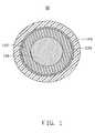
- FIG. 1is a schematic section view of a coaxial cable, in accordance with a first embodiment.
- FIG. 2is a schematic section view of an individual carbon nanotube coated with conductive coating, in accordance with the first embodiment.
- FIG. 3is a flow chart of a method for making the coaxial cable of FIG. 1 .
- FIG. 4is a system for making the coaxial cable as the method of FIG. 3 .
- FIG. 5shows a Scanning Electron Microscope (SEM) image of a carbon nanotube film used in the method for making the coaxial cable of FIG. 1 .
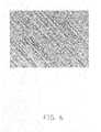
- FIG. 6shows a Scanning Electron Microscope (SEM) image of the carbon nanotube film with at least one layer of conductive coating individually coated on each carbon nanotube therein used in the method for making the coaxial cable of FIG. 1 .
- SEMScanning Electron Microscope
- FIG. 7shows a Transmission Electron Microscope (TEM) image of a carbon nanotube in the carbon nanotube film with at least one layer of conductive coating individually coated thereon of the carbon nanotube of FIG. 6 .
- TEMTransmission Electron Microscope
- FIG. 8shows a Scanning Electron Microscope (SEM) image of an individually coated twisted carbon nanotube wire-like structure, in accordance with the first embodiment.
- FIG. 9shows a Scanning Electron Microscope (SEM) image of the carbon nanotubes with at least one layer of conductive coating individually coated thereon in the twisted carbon nanotube wire-like structure of FIG. 8 .
- SEMScanning Electron Microscope
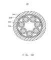
- FIG. 10shows a schematic section view of a coaxial cable, in accordance with a second embodiment.
- FIG. 11shows a schematic section view of a coaxial cable, in accordance with a third embodiment.
- a coaxial cable 10includes a core 110 , an insulating layer 120 wrapping the outer circumferential surface of the core 110 , a shielding layer 130 surrounding the outer circumferential surface of the insulating layer 120 , and a sheathing layer 140 covering the outer circumferential surface of the shielding layer 130 .
- the core 110 , the insulating layer 120 , the shielding layer 130 , and the sheathing layer 140are coaxial.
- the core 110has at least one carbon nanotube wire-like structure.
- the core 110includes a single carbon nanotube wire-like structure or a plurality of carbon nanotube wire-like structures.
- the core 110includes one carbon nanotube wire-like structure.
- a diameter of the carbon nanotube wire-like structurecan range from about 4.5 nanometers to about 1 millimeter or even larger (e.g., about 20 millimeters to 30 millimeters).
- the diameter of the carbon nanotube wire-like structureranges from about 1 micrometers to about 30 micrometers. It is to be understood that when the core 110 has a plurality of the carbon nanotube wire-like structure, the diameter of the core 110 can be set as desired.
- the carbon nanotube wire-like structureincludes a plurality of carbon nanotubes 111 (shown in FIG. 2 ) and at least one conductive coating covered on the outer surfaces of the carbon nanotubes.
- the one conductive coatingcomprises of at lease one conductive layer 114 .
- the carbon nanotubesare joined end-to-end by and combined by van der Waals attractive force between them.
- the carbon nanotube wire-like structurecan include a twisted carbon nanotube wire with a plurality of carbon nanotubes aligned around the axis of the carbon nanotube twisted wire like a helix.
- the carbon nanotube wire-like structurecan also include an non-twisted carbon nanotube wire, and the carbon nanotubes of the non-twisted carbon nanotube wire are arranged along an axis of the carbon nanotube wire-like structure (e.g., the carbon nanotubes are relatively straight and the axis of the carbon nanotubes are parallel to the axis of the non-twisted carbon nanotube wire).
- a diameter of the carbon nanotube wire-like structurecan range from about 4.5 nanometers to about 1 millimeter or even larger. In the present embodiment, the diameter of the carbon nanotube wire-like structure ranges from about 10 nanometers to about 30 micrometers.
- each of the carbon nanotubes 111 in the carbon nanotube wire-like structureis covered by the at least one conductive coating on the outer surface thereof.
- a conductive coatingis in direct contact with the outer surface of the individual carbon nanotube 111 .
- the at least one layer of conductive coatingfurther may include a wetting layer 112 , a transition layer 113 and an anti-oxidation layer 115 .
- the conductive coatinghas at least one conductive layer 114 .
- the at least one conductive coatingincludes a wetting layer 112 , that is applied to the outer circumferential surface of the carbon nanotube 111 , a transition layer 113 covering the outer circumferential surface of the wetting layer 112 , at least one conductive layer 114 wrapping the outer circumferential surface of the transition layer 113 , and an anti-oxidation layer 115 covering the outer circumferential surface of the conductive layer 114 .
- the wetting layer 112is configured to provide a good transition between the carbon nanotube 111 and the conductive layer 114 .
- the material of the wetting layer 112can be selected from the group consisting of iron (Fe), cobalt (Co), nickel (Ni), palladium (Pd), titanium (Ti), and any combination alloy thereof.
- a thickness of the wetting layer 112ranges from about 1 nanometer to about 10 nanometers. In the present embodiment, the material of the wetting layer 112 is Ni and the thickness of the wetting layer 112 is about 2 nanometers. The use of the wetting layer 112 is optional.
- the transition layer 113is arranged for combining the wetting layer 112 with the conductive layer 114 .
- the material of the transition layer 113should be one that works well both with the material of the wetting layer 112 and the material of the conductive layer 114 . Materials such as copper (Cu), silver (Ag), or alloys thereof can be used.
- a thickness of the transition layer 113ranges from about 1 nanometer to about 10 nanometers. In the present embodiment, the material of the transition layer 113 is Cu and the thickness is about 2 nanometers. The use of the transition layer 113 is optional.
- the conductive layer 114is arranged for enhancing the conductivity of the carbon nanotube twisted wire.
- the material of the conductive layer 114can be selected from any suitable conductive material including Cu, Ag, gold (Au) and combination alloys thereof.
- a thickness of the conductive layer 114ranges from about 1 nanometer to about 20 nanometers. In the first embodiment, the material of the conductive layer 114 is Ag and has a thickness of about 10 nanometers.
- the anti-oxidation layer 115is configured to prevent the conductive layer 114 from being oxidized by exposure to the air and prevent reduction of the conductivity of the core 110 .
- the material of the anti-oxidation layer 115can be any suitable material including gold (Au), platinum (Pt), and any other anti-oxidation metallic materials or combination alloys thereof.
- a thickness of the anti-oxidation layer 115ranges from about 1 nanometer to about 10 nanometers. In the present embodiment, the material of the anti-oxidation layer 115 is Pt and the thickness is about 2 nanometers.
- the use of the anti-oxidation layer 115is optional.
- a strengthening layer 116can be applied the outer surface of the conductive coating to enhance the strength of the coated carbon nanotubes.
- the material of the strengthening layer 116can be any suitable material including a polymer with high strength, such as polyvinyl acetate (PVA), polyvinyl chloride (PVC), polyethylene (PE), or paraphenylene benzobisoxazole (PBO).
- a thickness of the strengthening layer 116approximately ranges from 0.1 to 1 micron.
- the strengthening layer 116covers the anti-oxidation layer 115 , the material of the strengthening layer 116 is PVA, and the thickness of the strengthening layer 116 is about 0.5 microns.
- the use of the strengthening layer 116is optional.
- the insulating layer 120is used to insulate the core 110 .
- a material of the insulating layer 120can be any suitable insulated material such as polytetrafluoroethylene, polyethylene, polypropylene, polystyrene, polyethylene foam and nano-clay-polymer composite material.
- the material of the insulating layer 120is polyethylene foam.
- the shielding layer 130is made of electrically conductive material.
- the shielding layer 130is used to shield electromagnetic signals or external signals.
- the shielding layer 130can be formed by woven wires or by winding films around the insulating layer 120 .
- the wirescan be metal wires, carbon nanotube wires or composite wires having carbon nanotubes.
- the filmscan be metal films, carbon nanotube films or a composite film having carbon nanotubes.
- the carbon nanotubes in the carbon nanotube filmare arranged in an orderly manner or in a disorderly manner.
- a material of the metal wires or metal filmscan be any suitable material including copper, gold or silver, and other metals or their alloys having good electrical conductivity.
- the carbon nanotube wires and carbon nanotube filmsinclude a plurality of carbon nanotubes oriented along a preferred direction, joined end to end, and combined by van der Waals attractive force.
- the composite filmcan be composed of metals and carbon nanotubes, polymer and carbon nanotubes, or polymer and metals.
- the material of the polymercan be polyethylene terephthalate (PET), polycarbonate (PC), acrylonitrile-Butadiene Styrene Terpolymer (ABS), polycarbonate/acrylonitrile-butadiene-styrene (PC/ABS) polymer materials, or other suitable polymer.
- the shielding layer 130is a composite film having carbon nanotubes
- the shielding layer 130can be formed by dispersing carbon nanotubes in a solution of the composite to form a mixture, and coating the mixture on the insulating layer 120 .
- the shielding layer 130includes two or more layers formed by the wires or films or combination thereof.
- the sheathing layer 140is made of insulating material.
- the sheathing layer 140can be made of nano-clay-polymer composite materials.
- the nano-claycan be nano-kaolin clay or nano-montmorillonite.
- the polymercan be silicon resin, polyamide, polyolefin, such as polyethylene or polypropylene.
- the sheathing layer 140is made of nano-clay-polymer composite materials.
- the nano-clay-polymer composite materialhas good mechanical property, fire-resistant property, and can provide protection against damage from machinery, chemical exposure, etc.
- a method for making the coaxial cable 10includes the following steps: (a) providing a carbon nanotube structure 214 having a plurality of carbon nanotubes therein; (b) forming at least one conductive coating on each of the carbon nanotubes in the carbon nanotube structure 214 ; (c) forming an individually coated carbon nanotube wire-like structure 222 ; (d) forming at least one layer of insulating material on the carbon nanotube wire-like structure 222 ; (e) forming at least one layer of shielding material on the at least one layer of insulating material; and (f) forming one layer of sheathing material on the at least one layer of shielding material.
- the carbon nanotube structure 214can be a carbon nanotube film.
- the carbon nanotube filmcan be fabricated by the following substeps of: (a1) providing a carbon nanotube array 216 (e.g., a super-aligned carbon nanotube array 216 ); (a2) pulling out a carbon nanotube film from the carbon nanotube array 216 by using a tool (e.g., adhesive tape, pliers, tweezers, or another tool allowing multiple carbon nanotubes to be gripped and pulled simultaneously).
- a toole.g., adhesive tape, pliers, tweezers, or another tool allowing multiple carbon nanotubes to be gripped and pulled simultaneously.
- a super-aligned carbon nanotube array 216can be formed by a chemical vapor deposition method and in detail includes the following substeps: (a11) providing a substantially flat and smooth substrate; (a12) forming a catalyst layer on the substrate; (a13) annealing the substrate with the catalyst layer in air at a temperature approximately ranging from 700° C. to 900° C. for about 30 to 90 minutes; (a14) heating the substrate with the catalyst layer to a temperature approximately ranging from 500° C. to 740° C. in a furnace with a protective gas therein; and (a15) supplying a carbon source gas to the furnace for about 5 to 30 minutes to grow the super-aligned carbon nanotube array 216 on the substrate.
- the substratecan be a P-type silicon wafer, an N-type silicon wafer, or a silicon wafer with a film of silicon dioxide thereon.
- a 4-inch P-type silicon waferis used as the substrate.
- the catalystcan be made of iron (Fe), cobalt (Co), nickel (Ni), or any alloy thereof.
- the protective gascan be made up of at least one of nitrogen (N 2 ), ammonia (NH 3 ), and a noble gas.
- the carbon source gascan be a hydrocarbon gas, such as ethylene (C 2 H 4 ), methane (CH 4 ), acetylene (C 2 H 2 ), ethane (C 2 H 6 ), or any combination thereof.
- the super-aligned carbon nanotube array 216can be approximately 200 to 400 microns in height and includes a plurality of carbon nanotubes parallel to each other and approximately perpendicular to the substrate.
- the carbon nanotubes in the carbon nanotube array 216can be single-walled carbon nanotubes, double-walled carbon nanotubes, or multi-walled carbon nanotubes. Diameters of the single-walled carbon nanotubes approximately range from 0.5 nanometers to 10 nanometers. Diameters of the double-walled carbon nanotubes approximately range from 1 nanometer to 50 nanometers. Diameters of the multi-walled carbon nanotubes approximately range from 1.5 nanometers to 50 nanometers.
- the super-aligned carbon nanotube array 216 formed under the above conditionsis essentially free of impurities such as carbonaceous or residual catalyst particles.
- the carbon nanotubes in the super-aligned carbon nanotube array 216are closely packed together by van der Waals attractive force.
- the carbon nanotube filmcan be formed by the following substeps: (a21) selecting a plurality of carbon nanotube segments having a predetermined width from a carbon nanotube array 216 ; and (a22) pulling the carbon nanotube segments at an even/uniform speed to achieve the carbon nanotube film.
- the carbon nanotube segments having a predetermined widthcan be selected by using an adhesive tape such as the tool to contact the carbon nanotube array 216 .
- Each carbon nanotube segmentincludes a plurality of carbon nanotubes parallel to each other.
- the pulling directionis arbitrary (e.g., substantially perpendicular to the growing direction of the carbon nanotube array 216 ).
- the carbon nanotube filmincludes a plurality of carbon nanotubes joined end-to-end.
- the carbon nanotubes in the carbon nanotube filmare all substantially parallel to the pulling/drawing direction of the carbon nanotube film, and the carbon nanotube film produced in such manner can be selectively formed to have a predetermined width.
- the carbon nanotube film formed by the pulling/drawing methodhas superior uniformity of thickness and superior uniformity of conductivity over a typically disordered carbon nanotube film. Furthermore, the pulling/drawing method is simple, fast, and suitable for industrial applications.
- the length and width of the carbon nanotube filmdepends on a size of the carbon nanotube array 216 .
- the width of the carbon nanotube filmapproximately ranges from 0.01 centimeters to 10 centimeters
- the thickness of the carbon nanotube filmapproximately ranges from 0.5 nanometers to 100 microns
- the length of the the carbon nanotube filmcan reach to and above 100 meters.
- the at least one conductive coatingcan be formed on carbon nanotubes in the carbon nanotube structure 214 by a physical vapor deposition (PVD) method such as a vacuum evaporation or a sputtering.
- PVDphysical vapor deposition
- the at least one conductive coatingis formed by a vacuum evaporation method.
- the vacuum evaporation method for forming the at least one conductive coating of step (b)can further include the following substeps: (b1) providing a vacuum container 210 including at least one vaporizing source 212 ; and (b2) heating the at least one vaporizing source 212 to deposit the conductive coating on two opposite surfaces of the carbon nanotube structure 214 .
- the vacuum container 210includes a depositing zone therein.
- three pairs of vaporizing sources 212are respectively mounted on top and bottom portions of the depositing zone.
- Each pair of vaporizing sources 212includes an upper vaporizing source 212 located on a top surface of the depositing zone, and a lower vaporizing source 212 located on a bottom surface of the depositing zone.
- the two vaporizing sources 212are are on opposite sides of the vacuum container 210 .
- Each pair of vaporizing sources 212is made of a type of metallic material.
- the wetting layer 112 , the transition layer 113 , the conductive layer 114 , and the anti-oxidation layer 115can be orderly formed on the carbon nanotubes in the carbon nanotube structure 214 .
- the vaporizing sources 212can be arranged along a pulling direction of the carbon nanotube structure 214 on the top and bottom portions of the depositing zone.
- the carbon nanotube structure 214is located in the vacuum container 210 and between the upper vaporizing source 212 and the lower vaporizing source 212 . There is a distance between the carbon nanotube structure 214 and the vaporizing sources 212 .
- An upper surface of the carbon nanotube structure 214directly faces the upper vaporizing sources 212 .
- a lower surface of the carbon nanotube structure 214directly faces the lower vaporizing sources 212 .
- the vacuum container 210can be vacuum-exhausted by using of a vacuum pump (not shown).
- the vaporizing source 212can be heated by a heating device (not shown).
- the material in the vaporizing source 212is vaporized or sublimed to form a gas.
- the gasmeets the cold carbon nanotubes in the carbon nanotube structure 214 and coagulates on the upper surface and the lower surface of carbon nanotubes in the carbon nanotube structure 214 .
- the conductive materialcan be infiltrated in the interspaces between the carbon nanotubes in the carbon nanotube structure 214 . As such, the conductive material can be deposited on the outer surface of most, if not all, of the carbon nanotubes.
- a microstructure of the carbon nanotube structure 214 with at least one conductive coatingis shown in FIG. 6 and FIG. 7 .
- Each vaporizing source 212can have a corresponding depositing area by adjusting the distance between the carbon nanotube film and the vaporizing sources 212 .
- the vaporizing sources 212can be heated simultaneously, while the carbon nanotube structure 214 is pulled through the multiple depositing zones between the vaporizing sources 212 to form multiple layers of conductive material.
- the vacuum degree in the vacuum container 210can be above 1 Pascal (Pa). In the first embodiment, the vacuum degree is about 4 ⁇ 10 ⁇ 4 Pa.
- the carbon nanotube array 216 formed in step (a1)can be directly placed in the vacuum container 210 .
- the carbon nanotube structure 214such as carbon nanotube film can be pulled in the vacuum container 210 and successively pass each vaporizing source 212 , with each conductive coating continuously depositing.
- the pulling step and the depositing stepcan be performed simultaneously.
- the method for forming the at least one conductive coatingincludes the following steps: forming a wetting layer 112 on a surface of the carbon nanotube structure 214 ; forming a transition layer 113 on the wetting layer 112 ; forming a conductive layer 114 on the transition layer 113 ; and forming an anti-oxidation layer 115 on the conductive layer 114 .
- the steps of forming the wetting layer 112 , the transition layer 113 , and the anti-oxidation layer 115are optional.
- the method for forming at least one conductive coating on each of the carbon nanotubes in the carbon nanotube structure 214 in step (b)can be a physical method such as vacuum evaporating or sputtering as described above, and can also be a chemical method such as electroplating or electroless plating.
- the carbon nanotube structure 214can be disposed in a chemical solution.
- the step (b)further includes forming a strengthening layer outside the at least one conductive coating. More specifically, the carbon nanotube structure 214 with the at least one conductive coating can be immersed in a container 220 with a liquid polymer. Thus, the entire surface and spaces between the carbon nanotube structure 214 can be soaked with the liquid polymer. After concentration (i.e., being cured), the strengthening layer can be formed on the outside of the coated carbon nanotubes.
- step (c)when the carbon nanotube structure 214 is the carbon nanotube film having a relatively small width (e.g., about 0.5 nanometers to 100 microns), the carbon nanotube structure 214 with at least one conductive coating thereon can be seen as a carbon nanotube wire-like structure 222 without additional mechanical or chemical treatment.
- a relatively small widthe.g., about 0.5 nanometers to 100 microns
- the carbon nanotube wire-like structure 222can be made by a mechanical treatment (e.g., a conventional spinning or twisting process).
- the mechanical treatment to the carbon nanotube wire structure 222can be executed by twisting or cutting the carbon nanotube structure 214 with the at least one conductive coating along an aligned direction of the carbon nanotubes in the carbon nanotube structure 214 .
- One mannerincludes the following steps of: adhering one end of the carbon nanotube structure to a rotating motor; and twisting the carbon nanotube structure by the rotating motor to form the carbon nanotube wire-like structure 222 .
- a second mannerincludes the following steps of: supplying a spinning axis; contacting the spinning axis to one end of the carbon nanotube structure 214 ; and twisting the carbon nanotube structure 214 by the spinning axis.
- a plurality of carbon nanotube wire-like structures 222can be stacked or twisted to form one carbon nanotube wire-like structure with a larger diameter.
- a plurality of coated carbon nanotube structures 214can be arranged parallel to each other and then twisted to form the carbon nanotube wire-like structure with the large diameter.
- two or more coated carbon nanotube structures 214can be stacked and then twisted to form the carbon nanotube wire-like structure with the large diameter.
- about 500 layers of carbon nanotube filmsare stacked with each other and twisted to form a carbon nanotube wire-like structure 222 whose diameter can reach 3 millimeters. It is to be understood that the diameter can be even larger (e.g., 20 millimeters to 30 millimeters) and the coaxial cable can be used in electrical power transmission.
- the carbon nanotube wire-like structure 222includes a plurality of carbon nanotubes with at least one conductive coating and aligned around the axis of carbon nanotube wire-like structure 222 like a helix.
- the steps of forming the carbon nanotube structure 214 , the at least one conductive coating, and the strengthening layercan be processed in the vacuum container 210 to achieve a continuous production of the carbon nanotube wire-like structure 222 .
- the acquired carbon nanotube wire-like structure 222can be further collected by a first roller 224 .
- the carbon nanotube wire-like structure 222is coiled onto the first roller 224 .
- Step (d)can be executed by a first squeezing device 230 .
- the melting polymeris coated on an outer surface of the carbon nanotube wire-like structure 222 by the first squeezing device 230 .
- concentratione.g., being cured
- the insulating layer 120is formed.
- the polymeris polyethylene foam component.
- a layer of shielding materialcan be formed by woven wires or by winding films around the at least one layer of insulating material 120 .
- the shielding films 232can be provided by a second roller 234 .
- the wirescan be metal wires or carbon nanotube wires.
- the filmscan be metal films, carbon nanotube films or composite films having carbon nanotubes.
- the wirescan be winded on the at least one layer of insulating material 120 by a rack 236 .
- the carbon nanotubes in the carbon nanotube film capbe orderly and/or disorderly.
- Step (f)can be executed by a second squeezing device 240 .
- the sheathing materialis coated on an outer surface of the shielding layer 130 by the second squeezing device 240 to form the sheathing layer 140 .
- concentratione.g., being cured
- the sheathing layer 140is formed.
- the sheathing materialis nano-clay-polymer composite material.
- the acquired coaxial cable 10can be further collected by a third roller 260 by coiling the coaxial cable 10 onto a third roller 260 .
- the conductivity of the carbon nanotube wire-like structure 222is better than the conductivity of the carbon nanotube structure 214 without conductive coating on each carbon nanotube.
- the resistivity of the carbon nanotube wire-like structure 222can be ranged from about 10 ⁇ 10 ⁇ 8 ⁇ m to about 500 ⁇ 10 ⁇ 8 ⁇ m.
- the carbon nanotube wire-like structure 222has a diameter of about 120 microns, and a resistivity of about 360 ⁇ 10 ⁇ 8 ⁇ m.
- the resistivity of the carbon nanotube structure 214 without conductive coatingis about 1 ⁇ 10 ⁇ 5 ⁇ m ⁇ 2 ⁇ 10 ⁇ 5 ⁇ m.
- a coaxial cable 30includes a plurality of cores 310 , a plurality of insulating layers 320 , a shielding layer 330 , and a sheathing layer 340 .
- Each insulating layer 320wraps each core 310 .
- the shielding layer 330wraps the plurality of insulating layers 320 therein.
- the sheathing layer 340wraps the shielding layer 330 .
- Between the shielding layer 330 and the insulating layer 320insulating material is filled.
- the method for making the coaxial cable 30 of the second embodimentis similar to that of the coaxial cable 10 of the first embodiment.
- a coaxial cable 40 according to a third embodimentincludes a plurality of cores 410 , a plurality of insulating layer 420 , a plurality of shielding layer 430 , and a sheathing layer 440 .
- the insulating layer 430wraps each of the plurality of cores 410 .
- the shielding layer 430wraps each of the insulating layer 420 .
- the sheathing layer 440wraps all the shielding layers 430 .
- the method for making the coaxial cable 40 of the third embodimentis similar to that of the coaxial cable 10 of the first embodiment.
- each shielding layer 430can shield each core 410 respectively.
- the coaxial cable 40is configured to avoid interference coming from outer factors, and avoid interference between the plurality of cores 410 .
- the coaxial cable 10 , 30 , 40 provided in the embodimentshas the following superior properties. Firstly, the coaxial cable 10 , 30 , 40 includes a plurality of oriented carbon nanotubes joined end-to-end by van der Waals attractive force, whereby the coaxial cable has high strength and toughness. Secondly, the outer surface of each carbon nanotube is covered by at least one conductive coating, such that the core 110 , 210 , 410 made of carbon nanotubes has high conductivity. Thirdly, the method for making the core 110 , 210 , 410 of the coaxial cable 10 , 30 , 40 can be performed by drawing a carbon nanotube structure from a carbon nanotube array and forming at least one conductive coating on the carbon nanotube structure. The method is simple and relatively inexpensive.
- the coaxial cable 10 , 30 , 40can be formed continuously and, thus, a mass production thereof can be achieved.
- the carbon nanotubeshave a small diameter, and the cable includes a plurality of carbon nanotubes and at least one conductive coating thereon, thus the coaxial cable 10 , 30 , 40 has a smaller width than a metal wire formed by a conventional wire-drawing method and can be used in ultra-fine cables.
- the carbon nanotubesare hollow, and a thickness of the at least one layer of the conductive material is just several nanometers, thus a skin effect is less likely to occur in the coaxial cable 10 , 30 , 40 , and signals will not decay as much during transmission. Due to the diameters of the core and the carbon nanotube-wire like structure can be very large, the coaxial cable can be used in electrical power transmission.
- the carbon nanotubehas lower weight than metals, thus, the weight of the coaxial cable is decreased.
Landscapes
- Engineering & Computer Science (AREA)
- Manufacturing & Machinery (AREA)
- Carbon And Carbon Compounds (AREA)
- Insulated Conductors (AREA)
- Communication Cables (AREA)
Abstract
Description
Claims (23)
Applications Claiming Priority (3)
| Application Number | Priority Date | Filing Date | Title |
|---|---|---|---|
| CN200810066046.8 | 2008-02-01 | ||
| CN200810066046 | 2008-02-01 | ||
| CN200810066046 | 2008-02-01 |
Publications (2)
| Publication Number | Publication Date |
|---|---|
| US20090194313A1 US20090194313A1 (en) | 2009-08-06 |
| US7750240B2true US7750240B2 (en) | 2010-07-06 |
Family
ID=40930550
Family Applications (1)
| Application Number | Title | Priority Date | Filing Date |
|---|---|---|---|
| US12/321,572ActiveUS7750240B2 (en) | 2008-02-01 | 2009-01-22 | Coaxial cable |
Country Status (3)
| Country | Link |
|---|---|
| US (1) | US7750240B2 (en) |
| JP (1) | JP4424690B2 (en) |
| CN (2) | CN105244071B (en) |
Cited By (48)
| Publication number | Priority date | Publication date | Assignee | Title |
|---|---|---|---|---|
| US20090032741A1 (en)* | 2007-07-25 | 2009-02-05 | Nanocomp Technologies, Inc. | Systems and Methods for Controlling Chirality of Nanotubes |
| US20090042455A1 (en)* | 2007-08-07 | 2009-02-12 | Nanocomp Technologies, Inc. | Electrically and Thermally Non-Metallic Conductive Nanostructure-Based Adapters |
| US20090044848A1 (en)* | 2007-08-14 | 2009-02-19 | Nanocomp Technologies, Inc. | Nanostructured Material-Based Thermoelectric Generators |
| US20090047513A1 (en)* | 2007-02-27 | 2009-02-19 | Nanocomp Technologies, Inc. | Materials for Thermal Protection and Methods of Manufacturing Same |
| US20090075545A1 (en)* | 2007-07-09 | 2009-03-19 | Nanocomp Technologies, Inc. | Chemically-Assisted Alignment of Nanotubes Within Extensible Structures |
| US20090117025A1 (en)* | 2007-06-15 | 2009-05-07 | Nanocomp Technologies, Inc. | Injector Apparatus and Methods for Production of Nanostructures |
| US20090196982A1 (en)* | 2008-02-01 | 2009-08-06 | Tsinghua University | Method for making coaxial cable |
| US20090197082A1 (en)* | 2008-02-01 | 2009-08-06 | Tsinghua University | Individually coated carbon nanotube wire-like structure related applications |
| US20090196981A1 (en)* | 2008-02-01 | 2009-08-06 | Tsinghua University | Method for making carbon nanotube composite structure |
| US20090196985A1 (en)* | 2008-02-01 | 2009-08-06 | Tsinghua University | Method for making individually coated and twisted carbon nanotube wire-like structure |
| US20090215344A1 (en)* | 2005-07-28 | 2009-08-27 | Nanocomp Technologies, Inc. | Systems And Methods For Formation And Harvesting of Nanofibrous Materials |
| US20090255706A1 (en)* | 2008-04-09 | 2009-10-15 | Tsinghua University | Coaxial cable |
| US20090277897A1 (en)* | 2008-05-07 | 2009-11-12 | Nanocomp Technologies, Inc. | Nanostructure-based heating devices and methods of use |
| US20100000754A1 (en)* | 2008-05-07 | 2010-01-07 | Nanocomp Technologies, Inc. | Carbon nanotube-based coaxial electrical cables and wiring harness |
| US20100099319A1 (en)* | 2004-01-15 | 2010-04-22 | Nanocomp Technologies, Inc. | Systems and Methods for Synthesis of Extended Length Nanostructures |
| US20100104849A1 (en)* | 2005-05-03 | 2010-04-29 | Lashmore David S | Carbon composite materials and methods of manufacturing same |
| US20100233472A1 (en)* | 2008-02-01 | 2010-09-16 | Tsinghua University | Carbon nanotube composite film |
| US20110005808A1 (en)* | 2009-07-10 | 2011-01-13 | Nanocomp Technologies, Inc. | Hybrid Conductors and Method of Making Same |
| US20110051974A1 (en)* | 2009-08-25 | 2011-03-03 | Tsinghua University | Earphone cable and earphone using the same |
| US20110051973A1 (en)* | 2009-08-25 | 2011-03-03 | Tsinghua University | Earphone cable and earphone using the same |
| US20120149238A1 (en)* | 2009-09-17 | 2012-06-14 | Olympus Corporation | Mounting assembly and cable assembly |
| US20130025907A1 (en)* | 2011-07-26 | 2013-01-31 | Tyco Electronics Corporation | Carbon-based substrate conductor |
| US20130104396A1 (en)* | 2011-10-28 | 2013-05-02 | Hon Hai Precision Industry Co., Ltd. | Method for making pacemaker electrode lead |
| US8658897B2 (en) | 2011-07-11 | 2014-02-25 | Tangitek, Llc | Energy efficient noise dampening cables |
| US20140102781A1 (en)* | 2012-10-16 | 2014-04-17 | The Boeing Company | High Power, High Frequency Power Cable |
| US20140102755A1 (en)* | 2012-10-17 | 2014-04-17 | Commscope, Inc. Of North Carolina | Communications Cables Having Electrically Insulative but Thermally Conductive Cable Jackets |
| US8808792B2 (en) | 2012-01-17 | 2014-08-19 | Northrop Grumman Systems Corporation | Carbon nanotube conductor with enhanced electrical conductivity |
| US20140231118A1 (en)* | 2011-09-27 | 2014-08-21 | Cambridge Enterprise Limited | Materials and Methods for Insulation of Conducting Fibres, and Insulated Products |
| US20140334658A1 (en)* | 2013-05-08 | 2014-11-13 | Lite-On Technology Corporation | Wireless ear-hook headset, flexible tube structure thereof, and method for manufacturing the flexible tube structure |
| US9055667B2 (en) | 2011-06-29 | 2015-06-09 | Tangitek, Llc | Noise dampening energy efficient tape and gasket material |
| US20150262726A1 (en)* | 2014-03-12 | 2015-09-17 | Merry Electronics (Suzhou) Co., Ltd. | Graphene conducting wire and method of making the same |
| TWI508572B (en)* | 2013-05-08 | 2015-11-11 | Lite On Electronics Guangzhou | Ear-hook wireless headset, flexible tube structure thereof, and method for manufacturing the flexible tube structure |
| US9278856B2 (en) | 2011-04-08 | 2016-03-08 | Covestro Llc | Flexible sensing material containing carbon nanotubes |
| US9293233B2 (en) | 2013-02-11 | 2016-03-22 | Tyco Electronics Corporation | Composite cable |
| US9718691B2 (en) | 2013-06-17 | 2017-08-01 | Nanocomp Technologies, Inc. | Exfoliating-dispersing agents for nanotubes, bundles and fibers |
| US9782948B2 (en) | 2011-03-03 | 2017-10-10 | Tangitek, Llc | Antenna apparatus and method for reducing background noise and increasing reception sensitivity |
| TWI623410B (en)* | 2016-06-28 | 2018-05-11 | Pla技研股份有限公司 | Flexible tube and production apparatus therefor |
| US10109391B2 (en)* | 2017-02-20 | 2018-10-23 | Delphi Technologies, Inc. | Metallic/carbon nanotube composite wire |
| WO2020006042A1 (en)* | 2018-06-28 | 2020-01-02 | Carlisle Interconnect Technologies, Inc. | Coaxial cable utilizing a plated carbon nanotube elements and method of manufacturing same |
| US10581082B2 (en) | 2016-11-15 | 2020-03-03 | Nanocomp Technologies, Inc. | Systems and methods for making structures defined by CNT pulp networks |
| US10964451B2 (en) | 2018-11-06 | 2021-03-30 | The Esab Group Inc. | Cable hose with conductive electromagnetic interference shield |
| US20220021257A1 (en)* | 2019-03-29 | 2022-01-20 | Furukawa Electric Co., Ltd. | Coreless motor |
| US11279836B2 (en) | 2017-01-09 | 2022-03-22 | Nanocomp Technologies, Inc. | Intumescent nanostructured materials and methods of manufacturing same |
| US11426950B2 (en) | 2015-07-21 | 2022-08-30 | Tangitek, Llc | Electromagnetic energy absorbing three dimensional flocked carbon fiber composite materials |
| US11434581B2 (en) | 2015-02-03 | 2022-09-06 | Nanocomp Technologies, Inc. | Carbon nanotube structures and methods for production thereof |
| US11545280B2 (en) | 2018-08-23 | 2023-01-03 | The Esab Group Inc. | Cable hose with embedded features |
| US11600404B2 (en)* | 2016-06-20 | 2023-03-07 | Nexans | Electric cable comprising a metal layer |
| US12362077B2 (en)* | 2020-03-31 | 2025-07-15 | Furukawa Electric Co., Ltd. | Connection structure of carbon nanotube wire |
Families Citing this family (47)
| Publication number | Priority date | Publication date | Assignee | Title |
|---|---|---|---|---|
| US9111658B2 (en)* | 2009-04-24 | 2015-08-18 | Applied Nanostructured Solutions, Llc | CNS-shielded wires |
| EP2422595A1 (en) | 2009-04-24 | 2012-02-29 | Applied NanoStructured Solutions, LLC | Cnt-infused emi shielding composite and coating |
| CN102107867B (en)* | 2009-12-29 | 2012-12-19 | 北京富纳特创新科技有限公司 | Method for preparing carbon nano tube film |
| US9167736B2 (en) | 2010-01-15 | 2015-10-20 | Applied Nanostructured Solutions, Llc | CNT-infused fiber as a self shielding wire for enhanced power transmission line |
| TWI494267B (en)* | 2010-02-03 | 2015-08-01 | Beijing Funate Innovation Tech | Method for preparing nano carbon tube film |
| CN101880035A (en) | 2010-06-29 | 2010-11-10 | 清华大学 | carbon nanotube structure |
| FI20105841A0 (en)* | 2010-08-09 | 2010-08-09 | Spindeco Oy | SPIN CIRCUIT IN CARBON COATED WIRES |
| CN102372253B (en)* | 2010-08-23 | 2014-01-15 | 清华大学 | Carbon nanotube composite linear structure and preparation method thereof |
| CN102372255B (en) | 2010-08-23 | 2013-11-20 | 清华大学 | Device and method for preparing carbon nano tube compound linear structure |
| CN101976594A (en)* | 2010-08-31 | 2011-02-16 | 中国科学院苏州纳米技术与纳米仿生研究所 | Composite conductor application of carbon nano tube fiber and preparation method thereof |
| BR112012017246A2 (en)* | 2010-09-23 | 2016-03-22 | Applied Nanostructured Solutins Llc | cnt infused fiber as a self-shielded wire for enhanced power transmission line |
| CN102013376B (en) | 2010-11-29 | 2013-02-13 | 清华大学 | Field emission unit and field emission pixel tube |
| US20130087361A1 (en)* | 2011-10-11 | 2013-04-11 | Hitachi Cable, Ltd. | Foamed resin composition, wire and cable |
| CN103093859B (en)* | 2011-10-28 | 2015-08-26 | 清华大学 | Pacing lead and pacemaker |
| CN103093856B (en)* | 2011-10-28 | 2015-07-29 | 清华大学 | Electrode wires and apply the pacemaker of this electrode wires |
| CN103093865B (en) | 2011-10-28 | 2015-06-03 | 清华大学 | Pacemaker electrode line and pacemaker |
| CN103093858B (en)* | 2011-10-28 | 2016-10-19 | 清华大学 | Pacemaker lead and pacemaker |
| CN103083806B (en)* | 2011-10-28 | 2016-06-08 | 清华大学 | Pacing lead and pacemaker |
| CN103093857B (en) | 2011-10-28 | 2016-04-13 | 清华大学 | Electrode wires and apply the pacemaker of this electrode wires |
| CN103083808B (en) | 2011-10-28 | 2016-04-27 | 清华大学 | Pacing lead and pacemaker |
| CN103093860B (en)* | 2011-10-28 | 2016-04-13 | 清华大学 | Pacing lead and pacemaker |
| CN103157180B (en) | 2011-12-15 | 2015-04-01 | 清华大学 | Pacemaker electrode wire and pacemaker |
| CN103165211B (en) | 2011-12-15 | 2015-09-30 | 清华大学 | Pacing lead and pacemaker |
| US9085464B2 (en) | 2012-03-07 | 2015-07-21 | Applied Nanostructured Solutions, Llc | Resistance measurement system and method of using the same |
| CN102903416B (en)* | 2012-09-21 | 2015-01-21 | 左洪运 | Carbon fiber composite lead wire core and preparation method thereof |
| US9685258B2 (en)* | 2012-11-09 | 2017-06-20 | Northrop Grumman Systems Corporation | Hybrid carbon nanotube shielding for lightweight electrical cables |
| US9281152B2 (en)* | 2012-12-05 | 2016-03-08 | Eaton Corporation | Fuse with carbon fiber fusible element |
| EP2808873A1 (en)* | 2013-05-28 | 2014-12-03 | Nexans | Electrically conductive wire and method for its manufacture |
| CN105097065B (en)* | 2014-04-23 | 2018-03-02 | 北京富纳特创新科技有限公司 | CNT compound wire |
| CN104361930A (en)* | 2014-12-09 | 2015-02-18 | 成都国蓉科技有限公司 | Electromagnetic shielding lead wire |
| JP6462418B2 (en)* | 2015-02-27 | 2019-01-30 | 日立造船株式会社 | Carbon nanotube fiber manufacturing method, carbon nanotube fiber manufacturing apparatus, and carbon nanotube fiber |
| KR101883889B1 (en)* | 2015-02-27 | 2018-08-01 | 히다치 조센 가부시키가이샤 | Method for manufacturing carbon nanotube fiber, device for manufacturing carbon nanotube fiber, and carbon nanotube fiber |
| JP6462417B2 (en)* | 2015-02-27 | 2019-01-30 | 日立造船株式会社 | Carbon nanotube composite fiber manufacturing method, carbon nanotube composite fiber manufacturing apparatus, and carbon nanotube composite fiber |
| CN106571176A (en)* | 2015-10-10 | 2017-04-19 | 江南石墨烯研究院 | Flexible lead wire and manufacture method therefor |
| EP3598429A1 (en)* | 2015-11-12 | 2020-01-22 | Lg Electronics Inc. | Display device |
| CN107337192B (en)* | 2016-04-28 | 2019-10-25 | 清华大学 | A kind of preparation method of carbon nanotube rope |
| CN105845218A (en)* | 2016-05-18 | 2016-08-10 | 中天科技装备电缆有限公司 | Light total carbon cable and preparation method |
| CN106162954B (en)* | 2016-06-21 | 2019-09-13 | 北京旭江科技有限公司 | A kind of Nanotubes and preparation method thereof and its application as low-temperature heating body |
| US10115492B2 (en)* | 2017-02-24 | 2018-10-30 | Delphi Technologies, Inc. | Electrically conductive carbon nanotube wire having a metallic coating and methods of forming same |
| FR3068504B1 (en)* | 2017-06-30 | 2020-12-18 | Nexans | CABLE INCLUDING AN ELECTRICALLY CONDUCTIVE ELEMENT INCLUDING METALLIZED CARBON FIBERS |
| JP7083240B2 (en)* | 2017-09-11 | 2022-06-10 | 日立造船株式会社 | Manufacturing method of carbon nanotube wire |
| US10128022B1 (en) | 2017-10-24 | 2018-11-13 | Northrop Grumman Systems Corporation | Lightweight carbon nanotube cable comprising a pair of plated twisted wires |
| WO2019083039A1 (en)* | 2017-10-26 | 2019-05-02 | 古河電気工業株式会社 | Carbon nanotube composite wire, carbon nanotube-coated electric wire, and wire harness |
| CN111937088B (en)* | 2018-03-30 | 2023-01-31 | 古河电气工业株式会社 | Carbon nanotube-coated wire for coil, coil using carbon nanotube-coated wire for coil, and method for manufacturing carbon nanotube-coated wire coil |
| US11508498B2 (en)* | 2019-11-26 | 2022-11-22 | Trimtabs Ltd | Cables and methods thereof |
| WO2021134483A1 (en) | 2019-12-31 | 2021-07-08 | 瑞仪光电(苏州)有限公司 | Suspension cable structure and lighting device |
| KR102485264B1 (en)* | 2022-04-06 | 2023-01-06 | 현대자동차주식회사 | Heating wire and manufacturing method for heating wire |
Citations (11)
| Publication number | Priority date | Publication date | Assignee | Title |
|---|---|---|---|---|
| US4132828A (en) | 1976-11-26 | 1979-01-02 | Toho Beslon Co., Ltd. | Assembly of metal-coated carbon fibers, process for production thereof, and method for use thereof |
| US20040020681A1 (en)* | 2000-03-30 | 2004-02-05 | Olof Hjortstam | Power cable |
| US20040053780A1 (en) | 2002-09-16 | 2004-03-18 | Jiang Kaili | Method for fabricating carbon nanotube yarn |
| US20050170177A1 (en)* | 2004-01-29 | 2005-08-04 | Crawford Julian S. | Conductive filament |
| US7045716B2 (en)* | 2003-05-15 | 2006-05-16 | Nexans | Electrical cable |
| CN1992099A (en) | 2005-12-30 | 2007-07-04 | 鸿富锦精密工业(深圳)有限公司 | Conductive composite material and electric cable containing same |
| US20080170982A1 (en) | 2004-11-09 | 2008-07-17 | Board Of Regents, The University Of Texas System | Fabrication and Application of Nanofiber Ribbons and Sheets and Twisted and Non-Twisted Nanofiber Yarns |
| US7413474B2 (en)* | 2006-06-14 | 2008-08-19 | Tsinghua University | Composite coaxial cable employing carbon nanotubes therein |
| US7449631B2 (en)* | 2007-04-11 | 2008-11-11 | Tsinghua University | Coaxial cable |
| US7459627B2 (en)* | 2007-04-11 | 2008-12-02 | Tsinghua University | Coaxial cable |
| US7491883B2 (en)* | 2007-04-11 | 2009-02-17 | Tsinghua University | Coaxial cable |
Family Cites Families (2)
| Publication number | Priority date | Publication date | Assignee | Title |
|---|---|---|---|---|
| CN1282216C (en)* | 2002-09-16 | 2006-10-25 | 清华大学 | Filament and preparation method thereof |
| CN101003909A (en)* | 2006-12-21 | 2007-07-25 | 上海交通大学 | Electrochemical combined deposition method for preparing structure of composite membrane of Nano carbon tube - metal |
- 2009
- 2009-01-16CNCN201510592046.1Apatent/CN105244071B/enactiveActive
- 2009-01-16CNCNA2009100024594Apatent/CN101499331A/enactivePending
- 2009-01-16JPJP2009008218Apatent/JP4424690B2/enactiveActive
- 2009-01-22USUS12/321,572patent/US7750240B2/enactiveActive
Patent Citations (13)
| Publication number | Priority date | Publication date | Assignee | Title |
|---|---|---|---|---|
| US4132828A (en) | 1976-11-26 | 1979-01-02 | Toho Beslon Co., Ltd. | Assembly of metal-coated carbon fibers, process for production thereof, and method for use thereof |
| US20040020681A1 (en)* | 2000-03-30 | 2004-02-05 | Olof Hjortstam | Power cable |
| US20040053780A1 (en) | 2002-09-16 | 2004-03-18 | Jiang Kaili | Method for fabricating carbon nanotube yarn |
| CN1483667A (en) | 2002-09-16 | 2004-03-24 | �廪��ѧ | A carbon nanotube rope and its manufacturing method |
| US7045716B2 (en)* | 2003-05-15 | 2006-05-16 | Nexans | Electrical cable |
| US20050170177A1 (en)* | 2004-01-29 | 2005-08-04 | Crawford Julian S. | Conductive filament |
| US20080170982A1 (en) | 2004-11-09 | 2008-07-17 | Board Of Regents, The University Of Texas System | Fabrication and Application of Nanofiber Ribbons and Sheets and Twisted and Non-Twisted Nanofiber Yarns |
| CN1992099A (en) | 2005-12-30 | 2007-07-04 | 鸿富锦精密工业(深圳)有限公司 | Conductive composite material and electric cable containing same |
| US20070151744A1 (en) | 2005-12-30 | 2007-07-05 | Hon Hai Precision Industry Co., Ltd. | Electrical composite conductor and electrical cable using the same |
| US7413474B2 (en)* | 2006-06-14 | 2008-08-19 | Tsinghua University | Composite coaxial cable employing carbon nanotubes therein |
| US7449631B2 (en)* | 2007-04-11 | 2008-11-11 | Tsinghua University | Coaxial cable |
| US7459627B2 (en)* | 2007-04-11 | 2008-12-02 | Tsinghua University | Coaxial cable |
| US7491883B2 (en)* | 2007-04-11 | 2009-02-17 | Tsinghua University | Coaxial cable |
Non-Patent Citations (1)
| Title |
|---|
| Y .Zhang et al.Metal coating on suspended carbon nanotubes and its implication to metal-tube interaction,Chemical Physics Letters,Nov. 24, 2000,35-41,331,Elsevier Science. |
Cited By (75)
| Publication number | Priority date | Publication date | Assignee | Title |
|---|---|---|---|---|
| US20100099319A1 (en)* | 2004-01-15 | 2010-04-22 | Nanocomp Technologies, Inc. | Systems and Methods for Synthesis of Extended Length Nanostructures |
| US20100104849A1 (en)* | 2005-05-03 | 2010-04-29 | Lashmore David S | Carbon composite materials and methods of manufacturing same |
| US8999285B2 (en) | 2005-07-28 | 2015-04-07 | Nanocomp Technologies, Inc. | Systems and methods for formation and harvesting of nanofibrous materials |
| US10029442B2 (en) | 2005-07-28 | 2018-07-24 | Nanocomp Technologies, Inc. | Systems and methods for formation and harvesting of nanofibrous materials |
| US11413847B2 (en) | 2005-07-28 | 2022-08-16 | Nanocomp Technologies, Inc. | Systems and methods for formation and harvesting of nanofibrous materials |
| US7993620B2 (en) | 2005-07-28 | 2011-08-09 | Nanocomp Technologies, Inc. | Systems and methods for formation and harvesting of nanofibrous materials |
| US20090215344A1 (en)* | 2005-07-28 | 2009-08-27 | Nanocomp Technologies, Inc. | Systems And Methods For Formation And Harvesting of Nanofibrous Materials |
| US20090047513A1 (en)* | 2007-02-27 | 2009-02-19 | Nanocomp Technologies, Inc. | Materials for Thermal Protection and Methods of Manufacturing Same |
| US9061913B2 (en) | 2007-06-15 | 2015-06-23 | Nanocomp Technologies, Inc. | Injector apparatus and methods for production of nanostructures |
| US20090117025A1 (en)* | 2007-06-15 | 2009-05-07 | Nanocomp Technologies, Inc. | Injector Apparatus and Methods for Production of Nanostructures |
| US20090075545A1 (en)* | 2007-07-09 | 2009-03-19 | Nanocomp Technologies, Inc. | Chemically-Assisted Alignment of Nanotubes Within Extensible Structures |
| US8246886B2 (en) | 2007-07-09 | 2012-08-21 | Nanocomp Technologies, Inc. | Chemically-assisted alignment of nanotubes within extensible structures |
| US8057777B2 (en) | 2007-07-25 | 2011-11-15 | Nanocomp Technologies, Inc. | Systems and methods for controlling chirality of nanotubes |
| US20090032741A1 (en)* | 2007-07-25 | 2009-02-05 | Nanocomp Technologies, Inc. | Systems and Methods for Controlling Chirality of Nanotubes |
| US9236669B2 (en) | 2007-08-07 | 2016-01-12 | Nanocomp Technologies, Inc. | Electrically and thermally non-metallic conductive nanostructure-based adapters |
| US20090042455A1 (en)* | 2007-08-07 | 2009-02-12 | Nanocomp Technologies, Inc. | Electrically and Thermally Non-Metallic Conductive Nanostructure-Based Adapters |
| US20090044848A1 (en)* | 2007-08-14 | 2009-02-19 | Nanocomp Technologies, Inc. | Nanostructured Material-Based Thermoelectric Generators |
| US20090196982A1 (en)* | 2008-02-01 | 2009-08-06 | Tsinghua University | Method for making coaxial cable |
| US8268398B2 (en) | 2008-02-01 | 2012-09-18 | Tsinghua Universtiy | Method for making carbon nanotube composite structure |
| US20100233472A1 (en)* | 2008-02-01 | 2010-09-16 | Tsinghua University | Carbon nanotube composite film |
| US20090196985A1 (en)* | 2008-02-01 | 2009-08-06 | Tsinghua University | Method for making individually coated and twisted carbon nanotube wire-like structure |
| US8012585B2 (en) | 2008-02-01 | 2011-09-06 | Tsinghua University | Carbon nanotube composite film |
| US20090197082A1 (en)* | 2008-02-01 | 2009-08-06 | Tsinghua University | Individually coated carbon nanotube wire-like structure related applications |
| US8158199B2 (en) | 2008-02-01 | 2012-04-17 | Tsinghua University | Method for making individually coated and twisted carbon nanotube wire-like structure |
| US8247036B2 (en) | 2008-02-01 | 2012-08-21 | Tsinghua University | Method for making coaxial cable |
| US20090196981A1 (en)* | 2008-02-01 | 2009-08-06 | Tsinghua University | Method for making carbon nanotube composite structure |
| US20090255706A1 (en)* | 2008-04-09 | 2009-10-15 | Tsinghua University | Coaxial cable |
| US8604340B2 (en) | 2008-04-09 | 2013-12-10 | Tsinghua Univeristy | Coaxial cable |
| US9198232B2 (en) | 2008-05-07 | 2015-11-24 | Nanocomp Technologies, Inc. | Nanostructure-based heating devices and methods of use |
| US20090277897A1 (en)* | 2008-05-07 | 2009-11-12 | Nanocomp Technologies, Inc. | Nanostructure-based heating devices and methods of use |
| US9396829B2 (en) | 2008-05-07 | 2016-07-19 | Nanocomp Technologies, Inc. | Carbon nanotube-based coaxial electrical cables and wiring harness |
| US8847074B2 (en)* | 2008-05-07 | 2014-09-30 | Nanocomp Technologies | Carbon nanotube-based coaxial electrical cables and wiring harness |
| US20100000754A1 (en)* | 2008-05-07 | 2010-01-07 | Nanocomp Technologies, Inc. | Carbon nanotube-based coaxial electrical cables and wiring harness |
| US20110005808A1 (en)* | 2009-07-10 | 2011-01-13 | Nanocomp Technologies, Inc. | Hybrid Conductors and Method of Making Same |
| US8354593B2 (en) | 2009-07-10 | 2013-01-15 | Nanocomp Technologies, Inc. | Hybrid conductors and method of making same |
| US8363873B2 (en)* | 2009-08-25 | 2013-01-29 | Tsinghua University | Earphone cable and earphone using the same |
| US20110051974A1 (en)* | 2009-08-25 | 2011-03-03 | Tsinghua University | Earphone cable and earphone using the same |
| US8331602B2 (en)* | 2009-08-25 | 2012-12-11 | Tsinghua University | Earphone cable and earphone using the same |
| US20110051973A1 (en)* | 2009-08-25 | 2011-03-03 | Tsinghua University | Earphone cable and earphone using the same |
| US8298008B2 (en)* | 2009-09-17 | 2012-10-30 | Olympus Corporation | Mounting assembly and cable assembly |
| US20120149238A1 (en)* | 2009-09-17 | 2012-06-14 | Olympus Corporation | Mounting assembly and cable assembly |
| US9782948B2 (en) | 2011-03-03 | 2017-10-10 | Tangitek, Llc | Antenna apparatus and method for reducing background noise and increasing reception sensitivity |
| US9278856B2 (en) | 2011-04-08 | 2016-03-08 | Covestro Llc | Flexible sensing material containing carbon nanotubes |
| US9055667B2 (en) | 2011-06-29 | 2015-06-09 | Tangitek, Llc | Noise dampening energy efficient tape and gasket material |
| US10262775B2 (en) | 2011-07-11 | 2019-04-16 | Tangitek, Llc | Energy efficient noise dampening cables |
| US8658897B2 (en) | 2011-07-11 | 2014-02-25 | Tangitek, Llc | Energy efficient noise dampening cables |
| US20130025907A1 (en)* | 2011-07-26 | 2013-01-31 | Tyco Electronics Corporation | Carbon-based substrate conductor |
| US9520213B2 (en)* | 2011-09-27 | 2016-12-13 | Cambridge Enterprise Limited | Materials and methods for insulation of conducting fibres, and insulated products |
| US20140231118A1 (en)* | 2011-09-27 | 2014-08-21 | Cambridge Enterprise Limited | Materials and Methods for Insulation of Conducting Fibres, and Insulated Products |
| US20130104396A1 (en)* | 2011-10-28 | 2013-05-02 | Hon Hai Precision Industry Co., Ltd. | Method for making pacemaker electrode lead |
| US9084884B2 (en)* | 2011-10-28 | 2015-07-21 | Tsinghua University | Method for making pacemaker electrode lead |
| US8808792B2 (en) | 2012-01-17 | 2014-08-19 | Northrop Grumman Systems Corporation | Carbon nanotube conductor with enhanced electrical conductivity |
| US9449739B2 (en)* | 2012-10-16 | 2016-09-20 | The Boeing Company | High power, high frequency power cable |
| US20140102781A1 (en)* | 2012-10-16 | 2014-04-17 | The Boeing Company | High Power, High Frequency Power Cable |
| US20140102755A1 (en)* | 2012-10-17 | 2014-04-17 | Commscope, Inc. Of North Carolina | Communications Cables Having Electrically Insulative but Thermally Conductive Cable Jackets |
| US9293233B2 (en) | 2013-02-11 | 2016-03-22 | Tyco Electronics Corporation | Composite cable |
| US20140334658A1 (en)* | 2013-05-08 | 2014-11-13 | Lite-On Technology Corporation | Wireless ear-hook headset, flexible tube structure thereof, and method for manufacturing the flexible tube structure |
| US8983109B2 (en)* | 2013-05-08 | 2015-03-17 | Lite-On Electronics (Guangzhou) Limited | Wireless ear-hook headset, flexible tube structure thereof, and method for manufacturing the flexible tube structure |
| TWI508572B (en)* | 2013-05-08 | 2015-11-11 | Lite On Electronics Guangzhou | Ear-hook wireless headset, flexible tube structure thereof, and method for manufacturing the flexible tube structure |
| US9718691B2 (en) | 2013-06-17 | 2017-08-01 | Nanocomp Technologies, Inc. | Exfoliating-dispersing agents for nanotubes, bundles and fibers |
| US20150262726A1 (en)* | 2014-03-12 | 2015-09-17 | Merry Electronics (Suzhou) Co., Ltd. | Graphene conducting wire and method of making the same |
| US11434581B2 (en) | 2015-02-03 | 2022-09-06 | Nanocomp Technologies, Inc. | Carbon nanotube structures and methods for production thereof |
| US11426950B2 (en) | 2015-07-21 | 2022-08-30 | Tangitek, Llc | Electromagnetic energy absorbing three dimensional flocked carbon fiber composite materials |
| US11600404B2 (en)* | 2016-06-20 | 2023-03-07 | Nexans | Electric cable comprising a metal layer |
| TWI656010B (en)* | 2016-06-28 | 2019-04-11 | 日商Pla技研股份有限公司 | Hose and method of manufacturing same |
| TWI623410B (en)* | 2016-06-28 | 2018-05-11 | Pla技研股份有限公司 | Flexible tube and production apparatus therefor |
| US10581082B2 (en) | 2016-11-15 | 2020-03-03 | Nanocomp Technologies, Inc. | Systems and methods for making structures defined by CNT pulp networks |
| US11279836B2 (en) | 2017-01-09 | 2022-03-22 | Nanocomp Technologies, Inc. | Intumescent nanostructured materials and methods of manufacturing same |
| US10109391B2 (en)* | 2017-02-20 | 2018-10-23 | Delphi Technologies, Inc. | Metallic/carbon nanotube composite wire |
| US11424048B2 (en) | 2018-06-28 | 2022-08-23 | Carlisle Interconnect Technologies, Inc. | Coaxial cable utilizing plated carbon nanotube elements and method of manufacturing same |
| WO2020006042A1 (en)* | 2018-06-28 | 2020-01-02 | Carlisle Interconnect Technologies, Inc. | Coaxial cable utilizing a plated carbon nanotube elements and method of manufacturing same |
| US11545280B2 (en) | 2018-08-23 | 2023-01-03 | The Esab Group Inc. | Cable hose with embedded features |
| US10964451B2 (en) | 2018-11-06 | 2021-03-30 | The Esab Group Inc. | Cable hose with conductive electromagnetic interference shield |
| US20220021257A1 (en)* | 2019-03-29 | 2022-01-20 | Furukawa Electric Co., Ltd. | Coreless motor |
| US12362077B2 (en)* | 2020-03-31 | 2025-07-15 | Furukawa Electric Co., Ltd. | Connection structure of carbon nanotube wire |
Also Published As
| Publication number | Publication date |
|---|---|
| US20090194313A1 (en) | 2009-08-06 |
| CN101499331A (en) | 2009-08-05 |
| JP2009187943A (en) | 2009-08-20 |
| CN105244071A (en) | 2016-01-13 |
| JP4424690B2 (en) | 2010-03-03 |
| CN105244071B (en) | 2018-11-30 |
Similar Documents
| Publication | Publication Date | Title |
|---|---|---|
| US7750240B2 (en) | Coaxial cable | |
| US8247036B2 (en) | Method for making coaxial cable | |
| US20090197082A1 (en) | Individually coated carbon nanotube wire-like structure related applications | |
| US8158199B2 (en) | Method for making individually coated and twisted carbon nanotube wire-like structure | |
| US8268398B2 (en) | Method for making carbon nanotube composite structure | |
| JP5539663B2 (en) | coaxial cable | |
| US8012585B2 (en) | Carbon nanotube composite film | |
| EP2085979B1 (en) | Coaxial cable and method for making the same | |
| US8444947B2 (en) | Method for making carbon nanotube wire structure | |
| TW200945372A (en) | Cable | |
| US20100239850A1 (en) | Method for making composite material | |
| TW200939252A (en) | Cable | |
| TWI342027B (en) | Method for making twisted yarn | |
| EP2085976B1 (en) | Carbon nanotube composite material and method for making the same | |
| CN102110501B (en) | Preparation method of wire cable and cable core thereof | |
| CN111418028A (en) | Carbon nanotube coated wire | |
| TWI345794B (en) | Method for making cable | |
| TW201222563A (en) | Cable |
Legal Events
| Date | Code | Title | Description |
|---|---|---|---|
| AS | Assignment | Owner name:TSINGHUA UNIVERSITY, CHINA Free format text:ASSIGNMENT OF ASSIGNORS INTEREST;ASSIGNORS:JIANG, KAI-LI;LIU, LIANG;LIU, KAI;AND OTHERS;REEL/FRAME:022199/0776 Effective date:20081226 Owner name:HON HAI PRECISION INDUSTRY CO., LTD, TAIWAN Free format text:ASSIGNMENT OF ASSIGNORS INTEREST;ASSIGNORS:JIANG, KAI-LI;LIU, LIANG;LIU, KAI;AND OTHERS;REEL/FRAME:022199/0776 Effective date:20081226 | |
| AS | Assignment | Owner name:BEIJING FUNATE INNOVATION TECHNOLOGY CO., LTD., CH Free format text:ASSIGNMENT OF ASSIGNORS INTEREST;ASSIGNOR:TSINGHUA UNIVERSITY;REEL/FRAME:023020/0655 Effective date:20090721 | |
| STCF | Information on status: patent grant | Free format text:PATENTED CASE | |
| AS | Assignment | Owner name:ABBOTT CARDIOVASCULAR SYSTEMS INC., CALIFORNIA Free format text:ASSIGNMENT OF ASSIGNORS INTEREST;ASSIGNORS:KETAI, THEODORE;GREENBERG, JACOB;HALE, DANIEL;AND OTHERS;SIGNING DATES FROM 20111102 TO 20111121;REEL/FRAME:027436/0573 | |
| FPAY | Fee payment | Year of fee payment:4 | |
| MAFP | Maintenance fee payment | Free format text:PAYMENT OF MAINTENANCE FEE, 8TH YEAR, LARGE ENTITY (ORIGINAL EVENT CODE: M1552) Year of fee payment:8 | |
| MAFP | Maintenance fee payment | Free format text:PAYMENT OF MAINTENANCE FEE, 12TH YEAR, LARGE ENTITY (ORIGINAL EVENT CODE: M1553); ENTITY STATUS OF PATENT OWNER: LARGE ENTITY Year of fee payment:12 |