US7749257B2 - Bearing plate for use in fracture fixation having a spherical bearing hole with yielding expandability - Google Patents
Bearing plate for use in fracture fixation having a spherical bearing hole with yielding expandabilityDownload PDFInfo
- Publication number
- US7749257B2 US7749257B2US11/103,923US10392305AUS7749257B2US 7749257 B2US7749257 B2US 7749257B2US 10392305 AUS10392305 AUS 10392305AUS 7749257 B2US7749257 B2US 7749257B2
- Authority
- US
- United States
- Prior art keywords
- bearing
- hole
- plate
- bone
- spherical
- Prior art date
- Legal status (The legal status is an assumption and is not a legal conclusion. Google has not performed a legal analysis and makes no representation as to the accuracy of the status listed.)
- Expired - Fee Related, expires
Links
Images


Classifications
- A—HUMAN NECESSITIES
- A61—MEDICAL OR VETERINARY SCIENCE; HYGIENE
- A61B—DIAGNOSIS; SURGERY; IDENTIFICATION
- A61B17/00—Surgical instruments, devices or methods
- A61B17/56—Surgical instruments or methods for treatment of bones or joints; Devices specially adapted therefor
- A61B17/58—Surgical instruments or methods for treatment of bones or joints; Devices specially adapted therefor for osteosynthesis, e.g. bone plates, screws or setting implements
- A61B17/68—Internal fixation devices, including fasteners and spinal fixators, even if a part thereof projects from the skin
- A61B17/80—Cortical plates, i.e. bone plates; Instruments for holding or positioning cortical plates, or for compressing bones attached to cortical plates
- A61B17/8085—Cortical plates, i.e. bone plates; Instruments for holding or positioning cortical plates, or for compressing bones attached to cortical plates with pliable or malleable elements or having a mesh-like structure, e.g. small strips
Definitions
- the inventionrelates to a bearing plate adapted for use in fracture fixation, wherein the bearing plate has a spherical bearing hole adapted for receiving an expandable spherical bearing.
- the inventionrelates to improvements in the development of the bearing hole in the bearing plate.
- the inventionfurther relates to a method of moderating expansion force of an expandable spherical bearing in a bearing plate.
- the bearing plateserves as a fracture fixation plate adapted for being secured at one end to a bone fragment on one side of a bone fracture and a post is inserted through the bearing into another bone fragment on an opposite side of the fracture to stabilize it.
- the postalso serves as a means to expand the bearing and lock it in place in an adjusted angular position in the hole in the plate.
- microgroovesare provided on the surface of the bearing, these may become deformed and if the outer diameter of the bearing diminishes by even a small amount as the edges of the microgrooves are deformed, significant loss of wall reactive force may occur.
- An object of the inventionis to overcome the problems associated with the rigidity and stiffness of the hole in the plate which produce instantaneous resistance and unyielding property of the hole.
- a further object of the inventionis to provide an elastic expansion of the hole resulting in a substantially linear production of reactive force on the wall of the hole. This has the advantage that small changes in the bearing outer diameter as it expands do not produce such drastic changes in wall reactive force.
- a further object of the inventionis to provide a substantially lower modulus of elasticity of the plate at the hole as compared to the modulus of elasticity of the wall for a conventional hole.
- the bearing plateis provided with means at the spherical hole for providing yielding expansability at the hole so that as the bearing is expanded, the hole expands therewith to provide an elastic resistance to the expanding bearing.
- the means which provides the yielding expansability of the holeis obtained by forming one or more elastic segments which surround the hole and are capable of deforming outwardly as the bearing expands.
- the one or more segmentscan be formed by at least one slot extending outwardly from the hole.
- a radial slotextends from the hole and is joined to a circumferential slot to define two elastic segments capable of limited outward elastic deformation.
- one or more slotsare formed in the plate and extend outwardly and obliquely, for example circumferentially from the hole to form one or more elastic segments capable of deforming outwardly as the bearing expands.
- the slots which are formed in the plateare configured so that the elastic resistance which is produced at the hole is proportional to expansion of the bearing.
- the expandability of the holeis provided by forming a plurality of ridges at the surface of the hole which project inwardly to confront the outer surface of the bearing and be individually deformed as the bearing expands.
- a fracture fixation systemin which the bearing plate is secured at one end to a bone fragment at one side of a bone fracture and at an opposite side of the bone fracture the bearing plate has an expandable spherical bearing supported in a spherical hole in the plate and wherein the bearing receives a post which is inserted into another bone fragment on an opposite side of the fracture to stabilize it, the bearing plate being provided with means at the hole to provide resilient resistance to expansion of the bearing as the bearing is being locked into secured position in an adjusted angular position in the bearing plate.
- a methodfor moderating expansion force of the expanding spherical bearing in the hole of the bearing plate as the bearing is being expanded.
- one or more slotsare formed in the bearing plate and are configured to define one or more resilient segments facing the bearing and which deflect outwardly when the bearing is expanded to ease resistance of the plate at the hole to the expansion of the bearing.
- FIG. 1is a diagrammatic sectional view illustrating a fracture fixation system including means according to the invention.
- FIG. 2is a top view thereof.
- FIG. 3shows a stress-strain diagram when a conventional spherical bearing expands in a hole in a bearing plate of the fracture fixation system.
- FIG. 4shows a stress-strain diagram of the construction according to the invention.
- FIG. 5diagrammatically illustrates a first embodiment of means at the hole in the bearing plate for providing elastic expansion of the hole.
- FIG. 6diagrammatically illustrates a second embodiment.
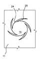
- FIG. 7diagrammatically illustrates a third embodiment.
- FIG. 8shows the embodiment of FIG. 7 after expansion of the hole.
- FIG. 9shows a modification of the third embodiment.
- FIG. 10shows the modification of FIG. 9 after expansion of the hole.
- FIG. 11diagrammatically illustrates a fourth embodiment.
- FIG. 12diagrammatically illustrates a fifth embodiment.
- FIG. 13shows the embodiment of FIG. 12 after expansion of the hole.
- the inventionis broadly concerned with the yieldability of a hole in a plate in which an expandable bearing is supported and expanded.
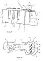
- FIGS. 1 and 2therein is shown on enlarged scale, the distal end portion of radius 1 of the wrist in which a fracture 2 is formed near the distal end 3 .
- the fracture 2defines an unstable distal bone fragment 4 and a stable proximal bone fragment 5 .
- Fixation of the fracture 2is achieved with a fracture fixation system 10 which includes a bearing plate 11 having a proximal portion 12 fixed to the stable bone fragment 5 by bone screws 13 .
- the bone screws 13may have smooth heads or threaded heads that lock into a threaded hole in the bearing plate.
- screwis used to refer to either type of fixation.
- the bearing plate 11has a distal portion 14 with a number of spherical holes 15 in which are secured fasteners 16 which enter and are secured in the distal unstable bone fragment 4 .
- the fasteners 16can be in the form of pins, rods, wires, or screws, and hereafter will be referred to as posts.
- the posts 16are secured in bearings 17 , which are adjustably secured in the holes 15 in the bearing plate to enable the posts to be positioned at different angles 18 in the unstable fragment 4 .
- the bearingis formed with one or more longitudinal slits (not shown) which enable expansion of the bearing in the hole 15 when the post is advanced in an axial bore in the bearing. Expansion of the bearing by advancement of the post axially therein is well known in the art and does not form any part of the present invention and therefore is not described in any detail herein.
- the postis normally screwed into the bone fragment and in order to hold the bearing in the hole as the post is screwed into the bone fragment, a key and keyway connection can be provided between the bearing and the plate.
- the hole 15has a predominantly spherical shape corresponding to that of the bearing and a clearance is provided between the bearing and the hole to allow the bearing to be angularly adjusted so that the post can be inserted at a proper angle into the bone fragment 4 .
- the postis axially advanced and expands the bearing to take up the clearance and thereafter press the bearing against the wall of the hole in the bearing plate to lock the bearing in the hole in the selected angular position.
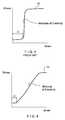
- FIG. 3shows a stress-strain diagram for an expanding bearing in a hole in a conventional plate.
- the bearingas it expands, takes up the clearance C after which the bearing presses against the wall of the hole and the force developed by the bearing against the plate rises rapidly until it reaches its ultimate limit UL.
- the slope of the stress-strain curvereferred to as the modulus of elasticity, is almost vertical as the wall of the hole offers little capability of expansion under the force of the expanding bearing.
- means 20is provided at the hole 15 for providing yielding expansability at the hole so that as the bearing is expanded, the hole expands therewith to provide elastic resistance to the expanding bearing.
- the stress-strain diagram for the expansion of the hole provided with means 20shows that after initially taking up the clearance C between the bearing and the wall of the hole, the stress developed between the bearing and the plate rises along a much less steep modulus of elasticity before reaching the fully-developed ultimate bearing pressure UL between the expanded bearing and the wall of the hole.
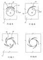
- FIG. 5shows a first embodiment 20 - 1 of the means for providing yielding expansability of the hole 15 when the bearing is expanded.
- FIG. 5which shows a portion of the plate 11 at one of the holes 15 , it is seen that a radial slot 21 is formed in the plate extending outwardly from the hole 15 .
- the radial slot 21extends into and is joined with a circumferential slot 22 to form segments 23 which act as elastic leaf springs. Accordingly, when the bearing is expanded, the segments 23 are capable of expanding with the expanding bearing to provide elastic resistance to the expansion of the bearing. This is evident by the reduction of the modulus of elasticity in the stress-strain diagram as shown in FIG. 4 .
- the segments 23can be provided with a defined elasticity to control the resistance to the expansion of the bearing within the hole 15 . As the bearing expands and the segments 23 are outwardly deformed, the segments compress the slot 22 until they reach the outer wall of slots 22 and the bearing now is fully secured in the hole 15 at the maximum stress UL.
- the ends of the slots 22may be provided with enlarged stress relief holes (not shown) to avoid crack propagation at the ends of the slots.
- FIG. 6shows a second embodiment 20 - 2 in which a slot 24 is provided which extends outwardly from the hole 15 in a radial direction and then obliquely in a circumferential direction to provide a flexible segment 25 which is capable of deflecting outwardly under the pressure of the expanding bearing to compress the slot 24 and eventually contact the outer wall of slot 24 when the bearing is expanded to reach the stress level UL.
- the slot 24gradually decreases from the hole 15 to its remote end.
- FIG. 7is a modification of FIG. 6 in which a plurality of slots 24 are distributed uniformly around the circumference of the hole 15 to form respective segments 25 which overlie one another.
- the principle of operationis the same as that in FIG. 6 except that since the segments 25 extend all around the hole 15 , they provide a uniformity for the resistance around the hole 15 for the expansion of the bearing.
- FIG. 8shows the segments 25 after they have been fully deflected by the expanded bearing and have compressed the slots 24 .
- FIG. 9shows a modification of the embodiment in FIG. 7 , and instead of having a uniformly graduated slot 24 as shown in FIG. 7 , the hole is formed with a step 28 facing the tip 29 of each segment 25 .
- the tip 29 of each segment 25bears against a respective step 28 and, as shown in FIG. 10 , causes the tip 29 to be inwardly displaced in facing relation to the expanding bearing.
- the tip 29is formed with a sharp pointed end 30 which serves as a tooth for biting into the outer periphery of the bearing when the bearing is expanded thereby to increase locking of the bearing in the hole.
- FIG. 11shows another embodiment 20 - 3 of the means for providing yielding expansibility at the hole in which a series of inwardly projecting ridges 40 are provided equally around the wall of the hole, the ridges extending along the thickness of the plate.
- the number of ridges 40 and the length thereof along the thickness of the plateis a function of the elasticity to be provided at the hole to the expandability of the bearing.
- the bearingexpands, it contacts the free inner ends of the ridges 40 , causing deformation of the ridges which results in a controlled elastic resistance to the expansion of the bearing and thereby achieve a stress-strain relation as shown in the stress-strain diagram of FIG. 4 .
- the ridges 40have pointed tips 41 to facilitate deformation of the ridges under the expansion pressure of the bearing.
- FIG. 12shows a further embodiment 20 - 4 of the means for providing yielding expansibility of the hole, wherein a plurality of radial slots 50 are provided around the periphery of the hole 15 so that individual segments 51 are formed between adjacent slots.
- a plurality of radial slots 50are provided around the periphery of the hole 15 so that individual segments 51 are formed between adjacent slots.
- the inner surfaces 52 of the segments 51are deformed, causing the slots to widen.
- the provision of the slots 50enables the segments 51 to provide an elastic resistance to the expansion of the bearing so that the relationship between the stress produced between the bearing and the surfaces 52 with respect to the compression deformation of the surfaces 52 will conform to the stress-strain diagram of FIG. 4 .
- bearings 17have been shown as being located at the distal end of the bearing plate 11 to receive posts 16 , bearings could also be located at the proximal end of the plate 11 to receive bone screws 13 or other fasteners.
- the inventionis broadly concerned with the installation of a fastener such as a pin, rod, wire, screw or the like in an expandible predominantly spherical bearing in a corresponding predominantly spherical hole.
- a platecan be provided with one or more expandable bearings at both ends of the plate, either alone or in combination with locked or unlocked screws as particularly applicable for fixation of spinal vertebrae, osteotomies and bone fusions.
Landscapes
- Health & Medical Sciences (AREA)
- Orthopedic Medicine & Surgery (AREA)
- Surgery (AREA)
- Life Sciences & Earth Sciences (AREA)
- Heart & Thoracic Surgery (AREA)
- Nuclear Medicine, Radiotherapy & Molecular Imaging (AREA)
- Engineering & Computer Science (AREA)
- Biomedical Technology (AREA)
- Neurology (AREA)
- Medical Informatics (AREA)
- Molecular Biology (AREA)
- Animal Behavior & Ethology (AREA)
- General Health & Medical Sciences (AREA)
- Public Health (AREA)
- Veterinary Medicine (AREA)
- Surgical Instruments (AREA)
Abstract
Description
Claims (30)
Priority Applications (1)
| Application Number | Priority Date | Filing Date | Title |
|---|---|---|---|
| US11/103,923US7749257B2 (en) | 2005-04-12 | 2005-04-12 | Bearing plate for use in fracture fixation having a spherical bearing hole with yielding expandability |
Applications Claiming Priority (1)
| Application Number | Priority Date | Filing Date | Title |
|---|---|---|---|
| US11/103,923US7749257B2 (en) | 2005-04-12 | 2005-04-12 | Bearing plate for use in fracture fixation having a spherical bearing hole with yielding expandability |
Publications (2)
| Publication Number | Publication Date |
|---|---|
| US20060241612A1 US20060241612A1 (en) | 2006-10-26 |
| US7749257B2true US7749257B2 (en) | 2010-07-06 |
Family
ID=37187972
Family Applications (1)
| Application Number | Title | Priority Date | Filing Date |
|---|---|---|---|
| US11/103,923Expired - Fee RelatedUS7749257B2 (en) | 2005-04-12 | 2005-04-12 | Bearing plate for use in fracture fixation having a spherical bearing hole with yielding expandability |
Country Status (1)
| Country | Link |
|---|---|
| US (1) | US7749257B2 (en) |
Cited By (14)
| Publication number | Priority date | Publication date | Assignee | Title |
|---|---|---|---|---|
| US20110118742A1 (en)* | 2009-05-12 | 2011-05-19 | Urs Hulliger | Readjustable Locking Plate Hole |
| US20110253159A1 (en)* | 2010-04-19 | 2011-10-20 | Babara Carey Stachowski | Expanding hair band |
| WO2012112986A3 (en)* | 2011-02-18 | 2013-02-21 | Intrinsic Medical, Llc | Surgical fastener and associated systems and methods |
| US20130310881A1 (en)* | 2012-05-17 | 2013-11-21 | Blackstone Medical, Inc. | Anti-backout mechanism for orthopedic devices |
| US8790379B2 (en) | 2010-06-23 | 2014-07-29 | Zimmer, Inc. | Flexible plate fixation of bone fractures |
| US8882815B2 (en) | 2010-06-23 | 2014-11-11 | Zimmer, Inc. | Flexible plate fixation of bone fractures |
| US9131969B2 (en) | 2011-06-30 | 2015-09-15 | Morgan Packard Lorio | Spinal plate and method for using same |
| US20150327897A1 (en)* | 2010-07-21 | 2015-11-19 | DePuy Synthes Products, Inc. | Device for Osteosynthesis |
| US9295508B2 (en) | 2012-02-03 | 2016-03-29 | Zimmer, Inc. | Bone plate for elastic osteosynthesis |
| US9510880B2 (en) | 2013-08-13 | 2016-12-06 | Zimmer, Inc. | Polyaxial locking mechanism |
| US9545275B2 (en) | 2007-05-18 | 2017-01-17 | Us Spine, Inc. | Medical device locking mechanisms and related methods and systems |
| US11324538B2 (en) | 2019-12-04 | 2022-05-10 | Biomet Manufacturing, Llc | Active bone plate |
| US20240067068A1 (en)* | 2022-08-26 | 2024-02-29 | Faurecia Interior Systems, Inc. | Vehicle interior panel and method of manufacture |
| US12220156B2 (en) | 2022-05-26 | 2025-02-11 | DePuy Synthes Products, Inc. | Orthopedic implant and method of use thereof |
Families Citing this family (21)
| Publication number | Priority date | Publication date | Assignee | Title |
|---|---|---|---|---|
| US8025681B2 (en) | 2006-03-29 | 2011-09-27 | Theken Spine, Llc | Dynamic motion spinal stabilization system |
| US8840650B2 (en)* | 2007-05-18 | 2014-09-23 | Us Spine, Inc. | Cervical plate locking mechanism and associated surgical method |
| EP3184065B1 (en) | 2007-11-09 | 2019-06-19 | Stryker European Holdings I, LLC | Cervical plate with a feedback device for selective association with bone screw blocking mechanism |
| US8652179B2 (en)* | 2008-05-02 | 2014-02-18 | The Cleveland Clinic Foundation | Bone plate extender and extension system for bone restoration and methods of use thereof |
| US8915918B2 (en)* | 2008-05-02 | 2014-12-23 | Thomas James Graham | Bone plate system for bone restoration and methods of use thereof |
| US8628533B2 (en)* | 2008-05-08 | 2014-01-14 | The Cleveland Clinic Foundation | Bone plate with reduction aids and methods of use thereof |
| US8608783B2 (en)* | 2008-05-08 | 2013-12-17 | The Cleveland Clinic Foundation | Bone plate with flange member and methods of use thereof |
| USD643121S1 (en) | 2010-05-27 | 2011-08-09 | Ebi, Llc | Orthopedic wrist spanning bone plate |
| USD646785S1 (en) | 2010-05-27 | 2011-10-11 | Ebi, Llc | Orthopedic volar bone plate |
| US8771324B2 (en) | 2011-05-27 | 2014-07-08 | Globus Medical, Inc. | Securing fasteners |
| AU2014365821B2 (en)* | 2013-12-20 | 2019-10-03 | Crossroads Extremity Systems, Llc | Polyaxial locking hole |
| US11202626B2 (en) | 2014-07-10 | 2021-12-21 | Crossroads Extremity Systems, Llc | Bone implant with means for multi directional force and means of insertion |
| JP2017529886A (en) | 2014-07-10 | 2017-10-12 | クロスローズ エクストリミティ システムズ リミテッド ライアビリティ カンパニー | Bone implant and means of insertion |
| WO2017011589A1 (en) | 2015-07-13 | 2017-01-19 | Crossroads Extremity Systems, Llc | Bone plates with dynamic elements |
| KR101846836B1 (en)* | 2016-08-10 | 2018-04-09 | 모미숙 | Osteosynthesis plate for periosteum injury prevention |
| US11864753B2 (en) | 2017-02-06 | 2024-01-09 | Crossroads Extremity Systems, Llc | Implant inserter |
| EP3579762B1 (en) | 2017-02-07 | 2024-06-26 | Crossroads Extremity Systems, LLC | Counter-torque implant |
| CN107330146B (en)* | 2017-05-26 | 2020-08-25 | 昆明理工大学 | Rock slope ultimate bearing capacity analysis upper limit method considering rotation effect |
| DE102017219168A1 (en)* | 2017-10-25 | 2019-04-25 | Bayerische Motoren Werke Aktiengesellschaft | Method for producing a component connection |
| US12059183B2 (en) | 2020-07-31 | 2024-08-13 | Crossroads Extremity Systems, Llc | Bone plates with dynamic elements and screws |
| USD961081S1 (en) | 2020-11-18 | 2022-08-16 | Crossroads Extremity Systems, Llc | Orthopedic implant |
Citations (15)
| Publication number | Priority date | Publication date | Assignee | Title |
|---|---|---|---|---|
| US4631783A (en)* | 1983-06-21 | 1986-12-30 | Kitagawa Industries Co., Ltd. | Holding unit |
| US4644610A (en)* | 1984-09-06 | 1987-02-24 | Fish Ivan L | Disc shaped holder with an expandable center hole |
| US5381588A (en)* | 1993-05-11 | 1995-01-17 | Nelson; Jeffrey A. | Retaining and display device |
| US5578034A (en)* | 1995-06-07 | 1996-11-26 | Danek Medical, Inc. | Apparatus for preventing screw backout in a bone plate fixation system |
| US6017345A (en)* | 1997-05-09 | 2000-01-25 | Spinal Innovations, L.L.C. | Spinal fixation plate |
| US6206882B1 (en)* | 1999-03-30 | 2001-03-27 | Surgical Dynamics Inc. | Plating system for the spine |
| US6235033B1 (en)* | 2000-04-19 | 2001-05-22 | Synthes (Usa) | Bone fixation assembly |
| US6261291B1 (en)* | 1999-07-08 | 2001-07-17 | David J. Talaber | Orthopedic implant assembly |
| US20040167521A1 (en)* | 2001-04-24 | 2004-08-26 | Paul De Windt | Fixing device for fixing vertebra parts |
| US20050043736A1 (en)* | 2001-12-24 | 2005-02-24 | Claude Mathieu | Device for osteosynthesis |
| US20050096657A1 (en)* | 2002-02-26 | 2005-05-05 | Alex Autericque | Osteosynthesis or arthrodesis material comprising a bony plate |
| US6979334B2 (en)* | 2003-07-07 | 2005-12-27 | Aesculap, Inc. | Bone fixation assembly and method of securement |
| US6989013B2 (en)* | 2001-09-25 | 2006-01-24 | Perumala Corporation | Medical appliance for bridging and stabilizing spaced apart bone segments having a bone screw locking system |
| US7175624B2 (en)* | 2002-12-31 | 2007-02-13 | Depuy Spine, Inc. | Bone plate and screw system allowing bi-directional assembly |
| US7276070B2 (en)* | 2003-06-11 | 2007-10-02 | Mueckter Helmut | Osteosynthesis plate or comparable implant plus ball socket |
- 2005
- 2005-04-12USUS11/103,923patent/US7749257B2/ennot_activeExpired - Fee Related
Patent Citations (15)
| Publication number | Priority date | Publication date | Assignee | Title |
|---|---|---|---|---|
| US4631783A (en)* | 1983-06-21 | 1986-12-30 | Kitagawa Industries Co., Ltd. | Holding unit |
| US4644610A (en)* | 1984-09-06 | 1987-02-24 | Fish Ivan L | Disc shaped holder with an expandable center hole |
| US5381588A (en)* | 1993-05-11 | 1995-01-17 | Nelson; Jeffrey A. | Retaining and display device |
| US5578034A (en)* | 1995-06-07 | 1996-11-26 | Danek Medical, Inc. | Apparatus for preventing screw backout in a bone plate fixation system |
| US6017345A (en)* | 1997-05-09 | 2000-01-25 | Spinal Innovations, L.L.C. | Spinal fixation plate |
| US6206882B1 (en)* | 1999-03-30 | 2001-03-27 | Surgical Dynamics Inc. | Plating system for the spine |
| US6261291B1 (en)* | 1999-07-08 | 2001-07-17 | David J. Talaber | Orthopedic implant assembly |
| US6235033B1 (en)* | 2000-04-19 | 2001-05-22 | Synthes (Usa) | Bone fixation assembly |
| US20040167521A1 (en)* | 2001-04-24 | 2004-08-26 | Paul De Windt | Fixing device for fixing vertebra parts |
| US6989013B2 (en)* | 2001-09-25 | 2006-01-24 | Perumala Corporation | Medical appliance for bridging and stabilizing spaced apart bone segments having a bone screw locking system |
| US20050043736A1 (en)* | 2001-12-24 | 2005-02-24 | Claude Mathieu | Device for osteosynthesis |
| US20050096657A1 (en)* | 2002-02-26 | 2005-05-05 | Alex Autericque | Osteosynthesis or arthrodesis material comprising a bony plate |
| US7175624B2 (en)* | 2002-12-31 | 2007-02-13 | Depuy Spine, Inc. | Bone plate and screw system allowing bi-directional assembly |
| US7276070B2 (en)* | 2003-06-11 | 2007-10-02 | Mueckter Helmut | Osteosynthesis plate or comparable implant plus ball socket |
| US6979334B2 (en)* | 2003-07-07 | 2005-12-27 | Aesculap, Inc. | Bone fixation assembly and method of securement |
Cited By (31)
| Publication number | Priority date | Publication date | Assignee | Title |
|---|---|---|---|---|
| US9545275B2 (en) | 2007-05-18 | 2017-01-17 | Us Spine, Inc. | Medical device locking mechanisms and related methods and systems |
| US20180078296A1 (en)* | 2009-05-12 | 2018-03-22 | DePuy Synthes Products, Inc. | Readjustable Locking Plate Hole |
| US10799275B2 (en)* | 2009-05-12 | 2020-10-13 | DePuy Synthes Products, Inc. | Readjustable locking plate hole |
| US9855082B2 (en)* | 2009-05-12 | 2018-01-02 | DePuy Synthes Products, Inc. | Readjustable locking plate hole |
| US20110118742A1 (en)* | 2009-05-12 | 2011-05-19 | Urs Hulliger | Readjustable Locking Plate Hole |
| US20110253159A1 (en)* | 2010-04-19 | 2011-10-20 | Babara Carey Stachowski | Expanding hair band |
| US8851086B2 (en)* | 2010-04-19 | 2014-10-07 | Conair Corporation | Expanding hair band |
| US9763713B2 (en) | 2010-06-23 | 2017-09-19 | Zimmer, Inc. | Flexible plate fixation of bone fractures |
| US8882815B2 (en) | 2010-06-23 | 2014-11-11 | Zimmer, Inc. | Flexible plate fixation of bone fractures |
| US11406433B2 (en) | 2010-06-23 | 2022-08-09 | Zimmer, Inc. | Flexible plate fixation of bone fractures |
| US10716605B2 (en) | 2010-06-23 | 2020-07-21 | Zimmer, Inc. | Flexible plate fixation of bone fractures |
| US10507049B2 (en) | 2010-06-23 | 2019-12-17 | Zimmer, Inc. | Flexible plate fixation of bone fractures |
| US9510879B2 (en) | 2010-06-23 | 2016-12-06 | Zimmer, Inc. | Flexible plate fixation of bone fractures |
| US8790379B2 (en) | 2010-06-23 | 2014-07-29 | Zimmer, Inc. | Flexible plate fixation of bone fractures |
| US8992583B2 (en) | 2010-06-23 | 2015-03-31 | Zimmer, Inc. | Flexible plate fixation of bone fractures |
| US9788873B2 (en) | 2010-06-23 | 2017-10-17 | Zimmer, Inc. | Flexible plate fixation of bone fractures |
| US9603641B2 (en)* | 2010-07-21 | 2017-03-28 | DePuy Synthes Products, Inc. | Device for osteosynthesis |
| US20150327897A1 (en)* | 2010-07-21 | 2015-11-19 | DePuy Synthes Products, Inc. | Device for Osteosynthesis |
| WO2012112986A3 (en)* | 2011-02-18 | 2013-02-21 | Intrinsic Medical, Llc | Surgical fastener and associated systems and methods |
| US9131969B2 (en) | 2011-06-30 | 2015-09-15 | Morgan Packard Lorio | Spinal plate and method for using same |
| US9295508B2 (en) | 2012-02-03 | 2016-03-29 | Zimmer, Inc. | Bone plate for elastic osteosynthesis |
| US10070905B2 (en) | 2012-02-03 | 2018-09-11 | Zimmer, Inc. | Flexible plate fixation of bone fractures |
| US9700361B2 (en) | 2012-02-03 | 2017-07-11 | Zimmer, Inc. | Bone plate for elastic osteosynthesis |
| US10022168B2 (en) | 2012-02-03 | 2018-07-17 | Zimmer, Inc. | Bone plate for elastic osteosynthesis |
| US20130310881A1 (en)* | 2012-05-17 | 2013-11-21 | Blackstone Medical, Inc. | Anti-backout mechanism for orthopedic devices |
| US9468481B2 (en)* | 2012-05-17 | 2016-10-18 | Blackstone Medical, Inc. | Anti-backout mechanism for orthopedic devices |
| US9867643B2 (en) | 2013-08-13 | 2018-01-16 | Zimmer, Inc. | Polyaxial locking mechanism |
| US9510880B2 (en) | 2013-08-13 | 2016-12-06 | Zimmer, Inc. | Polyaxial locking mechanism |
| US11324538B2 (en) | 2019-12-04 | 2022-05-10 | Biomet Manufacturing, Llc | Active bone plate |
| US12220156B2 (en) | 2022-05-26 | 2025-02-11 | DePuy Synthes Products, Inc. | Orthopedic implant and method of use thereof |
| US20240067068A1 (en)* | 2022-08-26 | 2024-02-29 | Faurecia Interior Systems, Inc. | Vehicle interior panel and method of manufacture |
Also Published As
| Publication number | Publication date |
|---|---|
| US20060241612A1 (en) | 2006-10-26 |
Similar Documents
| Publication | Publication Date | Title |
|---|---|---|
| US7749257B2 (en) | Bearing plate for use in fracture fixation having a spherical bearing hole with yielding expandability | |
| JP2960688B2 (en) | Bone fixation screw | |
| US5976141A (en) | Threaded insert for bone plate screw hole | |
| EP1997450B1 (en) | Bone anchoring element | |
| CA2629225C (en) | Orthopedic implant assembly | |
| JP5658236B2 (en) | Re-adjustable fixing plate hole | |
| US8216283B2 (en) | Device for osteosynthesis | |
| US7879036B2 (en) | Bone anchoring element | |
| AU2004314410B2 (en) | Fracture fixation system | |
| US7867239B2 (en) | Vertebral plating system | |
| US20070270832A1 (en) | Locking device and method, for use in a bone stabilization system, employing a set screw member and deformable saddle member | |
| US9237911B2 (en) | Locking pin plate assembly adapted for fracture fixation | |
| US20150088209A1 (en) | Bone anchoring element | |
| US20040133204A1 (en) | Expandable bone nails | |
| AU700415B2 (en) | A fixing element for osteosynthesis | |
| US11219470B2 (en) | Modular tensioned spinal screw | |
| US20110029025A1 (en) | Locking pin plate assembly adapted for fracture fixation | |
| US10603084B1 (en) | Systems for treatment of spinal deformities | |
| JP2003530196A (en) | Bone fixation assembly | |
| AU2017367581B2 (en) | Bioabsorbable deformable anchors | |
| WO2004096067A2 (en) | Bone fixture apparatus | |
| US20090030463A1 (en) | Occipital fixation screw | |
| CN116585018A (en) | Reinforced medical screw expansion sleeve | |
| US20130018420A1 (en) | Spine Fixation Device Containing Set Screw Having Double Spiral Form | |
| JP2023535584A (en) | An osteosynthesis device comprising at least one fixation pin |
Legal Events
| Date | Code | Title | Description |
|---|---|---|---|
| AS | Assignment | Owner name:MEDOFF, DAVID, CALIFORNIA Free format text:ASSIGNMENT OF ASSIGNORS INTEREST;ASSIGNOR:MEDOFF, ROBERT J.;REEL/FRAME:016467/0883 Effective date:20050330 Owner name:TELLMAN, LARS G., SWEDEN Free format text:ASSIGNMENT OF ASSIGNORS INTEREST;ASSIGNOR:MEDOFF, ROBERT J.;REEL/FRAME:016467/0883 Effective date:20050330 Owner name:MEDOFF, ROBERT J., HAWAII Free format text:ASSIGNMENT OF ASSIGNORS INTEREST;ASSIGNOR:MEDOFF, ROBERT J.;REEL/FRAME:016467/0883 Effective date:20050330 | |
| STCF | Information on status: patent grant | Free format text:PATENTED CASE | |
| FPAY | Fee payment | Year of fee payment:4 | |
| MAFP | Maintenance fee payment | Free format text:PAYMENT OF MAINTENANCE FEE, 8TH YR, SMALL ENTITY (ORIGINAL EVENT CODE: M2552) Year of fee payment:8 | |
| FEPP | Fee payment procedure | Free format text:MAINTENANCE FEE REMINDER MAILED (ORIGINAL EVENT CODE: REM.); ENTITY STATUS OF PATENT OWNER: SMALL ENTITY | |
| LAPS | Lapse for failure to pay maintenance fees | Free format text:PATENT EXPIRED FOR FAILURE TO PAY MAINTENANCE FEES (ORIGINAL EVENT CODE: EXP.); ENTITY STATUS OF PATENT OWNER: SMALL ENTITY | |
| STCH | Information on status: patent discontinuation | Free format text:PATENT EXPIRED DUE TO NONPAYMENT OF MAINTENANCE FEES UNDER 37 CFR 1.362 | |
| STCH | Information on status: patent discontinuation | Free format text:PATENT EXPIRED DUE TO NONPAYMENT OF MAINTENANCE FEES UNDER 37 CFR 1.362 | |
| FP | Lapsed due to failure to pay maintenance fee | Effective date:20220706 |