US7749247B2 - Tissue puncture closure device with coiled automatic tamping system - Google Patents
Tissue puncture closure device with coiled automatic tamping systemDownload PDFInfo
- Publication number
- US7749247B2 US7749247B2US11/197,382US19738205AUS7749247B2US 7749247 B2US7749247 B2US 7749247B2US 19738205 AUS19738205 AUS 19738205AUS 7749247 B2US7749247 B2US 7749247B2
- Authority
- US
- United States
- Prior art keywords
- coil
- driving plate
- closure device
- tissue puncture
- housing
- Prior art date
- Legal status (The legal status is an assumption and is not a legal conclusion. Google has not performed a legal analysis and makes no representation as to the accuracy of the status listed.)
- Active, expires
Links
- 238000007789sealingMethods0.000claimsabstractdescription121
- 238000003780insertionMethods0.000claimsdescription32
- 230000037431insertionEffects0.000claimsdescription32
- 238000007667floatingMethods0.000claimsdescription7
- 238000000034methodMethods0.000abstractdescription38
- 230000002463transducing effectEffects0.000abstractdescription2
- 210000001367arteryAnatomy0.000description28
- 102000008186CollagenHuman genes0.000description16
- 108010035532CollagenProteins0.000description16
- 229920001436collagenPolymers0.000description16
- 230000002792vascularEffects0.000description6
- 208000032843HemorrhageDiseases0.000description5
- 208000034158bleedingDiseases0.000description5
- 230000000740bleeding effectEffects0.000description5
- 239000000463materialSubstances0.000description5
- 230000000694effectsEffects0.000description4
- 230000008901benefitEffects0.000description3
- 210000004204blood vesselAnatomy0.000description3
- 210000001105femoral arteryAnatomy0.000description3
- 230000013011matingEffects0.000description3
- 230000003213activating effectEffects0.000description2
- 239000000515collagen spongeSubstances0.000description2
- 238000000151depositionMethods0.000description2
- 229920003023plasticPolymers0.000description2
- 239000004033plasticSubstances0.000description2
- 229920000642polymerPolymers0.000description2
- 206010003210ArteriosclerosisDiseases0.000description1
- 238000004873anchoringMethods0.000description1
- 238000002399angioplastyMethods0.000description1
- 208000011775arteriosclerosis diseaseDiseases0.000description1
- 230000003143atherosclerotic effectEffects0.000description1
- 230000000747cardiac effectEffects0.000description1
- 230000006835compressionEffects0.000description1
- 238000007906compressionMethods0.000description1
- 230000008021depositionEffects0.000description1
- 230000000994depressogenic effectEffects0.000description1
- 238000006073displacement reactionMethods0.000description1
- 239000002657fibrous materialSubstances0.000description1
- 239000006260foamSubstances0.000description1
- 210000000232gallbladderAnatomy0.000description1
- 210000002216heartAnatomy0.000description1
- 230000023597hemostasisEffects0.000description1
- 230000002439hemostatic effectEffects0.000description1
- 238000002347injectionMethods0.000description1
- 239000007924injectionSubstances0.000description1
- 210000004185liverAnatomy0.000description1
- 238000012986modificationMethods0.000description1
- 230000004048modificationEffects0.000description1
- 210000000056organAnatomy0.000description1
- 238000012856packingMethods0.000description1
- 229920002635polyurethanePolymers0.000description1
- 239000004814polyurethaneSubstances0.000description1
- 230000002028prematureEffects0.000description1
- 238000000926separation methodMethods0.000description1
- 239000000126substanceSubstances0.000description1
- 238000001356surgical procedureMethods0.000description1
- 208000019553vascular diseaseDiseases0.000description1
- 238000004804windingMethods0.000description1
Images


Classifications
- A—HUMAN NECESSITIES
- A61—MEDICAL OR VETERINARY SCIENCE; HYGIENE
- A61B—DIAGNOSIS; SURGERY; IDENTIFICATION
- A61B17/00—Surgical instruments, devices or methods
- A61B17/0057—Implements for plugging an opening in the wall of a hollow or tubular organ, e.g. for sealing a vessel puncture or closing a cardiac septal defect
- A—HUMAN NECESSITIES
- A61—MEDICAL OR VETERINARY SCIENCE; HYGIENE
- A61B—DIAGNOSIS; SURGERY; IDENTIFICATION
- A61B17/00—Surgical instruments, devices or methods
- A61B17/04—Surgical instruments, devices or methods for suturing wounds; Holders or packages for needles or suture materials
- A61B17/0401—Suture anchors, buttons or pledgets, i.e. means for attaching sutures to bone, cartilage or soft tissue; Instruments for applying or removing suture anchors
- A—HUMAN NECESSITIES
- A61—MEDICAL OR VETERINARY SCIENCE; HYGIENE
- A61B—DIAGNOSIS; SURGERY; IDENTIFICATION
- A61B17/00—Surgical instruments, devices or methods
- A61B17/04—Surgical instruments, devices or methods for suturing wounds; Holders or packages for needles or suture materials
- A61B17/06—Needles ; Sutures; Needle-suture combinations; Holders or packages for needles or suture materials
- A61B17/06114—Packages or dispensers for needles or sutures
- A61B17/06119—Packages or dispensers for needles or sutures of cylindrical shape
- A61B17/06123—Flat cylinders, e.g. including an inner reel
- A—HUMAN NECESSITIES
- A61—MEDICAL OR VETERINARY SCIENCE; HYGIENE
- A61B—DIAGNOSIS; SURGERY; IDENTIFICATION
- A61B17/00—Surgical instruments, devices or methods
- A61B17/04—Surgical instruments, devices or methods for suturing wounds; Holders or packages for needles or suture materials
- A61B17/06—Needles ; Sutures; Needle-suture combinations; Holders or packages for needles or suture materials
- A61B17/06166—Sutures
- A—HUMAN NECESSITIES
- A61—MEDICAL OR VETERINARY SCIENCE; HYGIENE
- A61B—DIAGNOSIS; SURGERY; IDENTIFICATION
- A61B17/00—Surgical instruments, devices or methods
- A61B17/0057—Implements for plugging an opening in the wall of a hollow or tubular organ, e.g. for sealing a vessel puncture or closing a cardiac septal defect
- A61B2017/00637—Implements for plugging an opening in the wall of a hollow or tubular organ, e.g. for sealing a vessel puncture or closing a cardiac septal defect for sealing trocar wounds through abdominal wall
- A—HUMAN NECESSITIES
- A61—MEDICAL OR VETERINARY SCIENCE; HYGIENE
- A61B—DIAGNOSIS; SURGERY; IDENTIFICATION
- A61B17/00—Surgical instruments, devices or methods
- A61B17/0057—Implements for plugging an opening in the wall of a hollow or tubular organ, e.g. for sealing a vessel puncture or closing a cardiac septal defect
- A61B2017/00646—Type of implements
- A61B2017/00654—Type of implements entirely comprised between the two sides of the opening
- A—HUMAN NECESSITIES
- A61—MEDICAL OR VETERINARY SCIENCE; HYGIENE
- A61B—DIAGNOSIS; SURGERY; IDENTIFICATION
- A61B17/00—Surgical instruments, devices or methods
- A61B17/0057—Implements for plugging an opening in the wall of a hollow or tubular organ, e.g. for sealing a vessel puncture or closing a cardiac septal defect
- A61B2017/00646—Type of implements
- A61B2017/00659—Type of implements located only on one side of the opening
- A—HUMAN NECESSITIES
- A61—MEDICAL OR VETERINARY SCIENCE; HYGIENE
- A61B—DIAGNOSIS; SURGERY; IDENTIFICATION
- A61B17/00—Surgical instruments, devices or methods
- A61B17/04—Surgical instruments, devices or methods for suturing wounds; Holders or packages for needles or suture materials
- A61B17/0401—Suture anchors, buttons or pledgets, i.e. means for attaching sutures to bone, cartilage or soft tissue; Instruments for applying or removing suture anchors
- A61B2017/0414—Suture anchors, buttons or pledgets, i.e. means for attaching sutures to bone, cartilage or soft tissue; Instruments for applying or removing suture anchors having a suture-receiving opening, e.g. lateral opening
- A—HUMAN NECESSITIES
- A61—MEDICAL OR VETERINARY SCIENCE; HYGIENE
- A61B—DIAGNOSIS; SURGERY; IDENTIFICATION
- A61B17/00—Surgical instruments, devices or methods
- A61B17/04—Surgical instruments, devices or methods for suturing wounds; Holders or packages for needles or suture materials
- A61B17/0401—Suture anchors, buttons or pledgets, i.e. means for attaching sutures to bone, cartilage or soft tissue; Instruments for applying or removing suture anchors
- A61B2017/0417—T-fasteners
- A—HUMAN NECESSITIES
- A61—MEDICAL OR VETERINARY SCIENCE; HYGIENE
- A61B—DIAGNOSIS; SURGERY; IDENTIFICATION
- A61B17/00—Surgical instruments, devices or methods
- A61B17/04—Surgical instruments, devices or methods for suturing wounds; Holders or packages for needles or suture materials
- A61B2017/0496—Surgical instruments, devices or methods for suturing wounds; Holders or packages for needles or suture materials for tensioning sutures
Definitions
- This inventionrelates generally to medical devices and more particularly to devices for sealing punctures or incisions in a tissue wall.
- vascular diseasesuch as arteriosclerosis
- an instrumente.g., a balloon or other type of catheter
- Such proceduresusually involve the percutaneous puncture of the artery so that an insertion sheath can be placed in the artery and thereafter instruments (e.g., catheter) can pass through the sheath and to an operative position within the artery.
- instrumentse.g., catheter
- Intravascular and intraluminal proceduresunavoidably present the problem of stopping the bleeding at the percutaneous puncture after the procedure has been completed and after the instruments (and any insertion sheaths used therewith) have been removed.
- Bleeding from puncture sitesis typically stopped by utilizing vascular closure devices, such as those described in U.S. Pat. Nos. 6,179,963; 6,090,130; and 6,045,569 and related patents that are hereby incorporated by reference.
- Typical closure devicessuch as the ones described in the above-mentioned patents place a sealing plug at the tissue puncture site.
- Successful deployment of the sealing plugrequires that it be manually ejected from within a device sheath and tamped down to an outer surface of the tissue puncture using a tamping tube.
- the tamping procedurecannot commence until the device sheath (within which the tamping tube is located) has been removed so as to expose the tamping tube for manual grasping.
- the present inventionmeets the above-described needs and others. Specifically, the present invention provides methods and systems for closing internal tissue punctures. However, unlike prior systems, the present invention provides automatic tamping to a sealing plug as the closure device is retracted. In addition, the present invention allows the automatic tamping system to disengage, facilitating full retraction of the closure device and easy separation of the sealing plug from the remainder of the closure device.
- the present inventionprovides an apparatus comprising a tissue puncture closure device, the tissue puncture closure device comprising an anchor, a sealing plug, a connector slidingly attaching the sealing plug to the anchor, and a coil operatively connected to the sealing plug for automatically tamping the sealing plug toward the anchor.
- the tissue puncture closure devicemay further comprise a tamping tube disposed adjacent to the sealing plug, such that the tamping tube is driven by the coil to tamp the sealing plug.
- the tissue puncture closure devicemay further comprise a housing, a block disposed in the housing and receptive of at least a portion of the coil, and a driving plate adjacent to the coil.
- the blockmay comprise a curved channel
- the driving platemay comprise a drive pin extending into the curved channel adjacent to a first end of the coil.
- the apparatusmay comprise a spool connected to the driving plate, where a portion of the filament is wound around the spool.
- the spoolmay be connected by a releasable clutch to the driving plate.
- the blockmay comprise a spiraled channel receptive of at least a portion of the coil
- the driving platemay comprise a drive pin extending into the spiraled channel adjacent to a first end of the coil.
- the driving platemay comprise a radially floating, angularly stable drive pin extending into the spiraled channel adjacent to the first end of the coil.
- the driving platemay comprise a radially compliant, angularly stable drive pin extending into the spiraled channel adjacent to the first end of the coil.
- the block disposed in the housingcomprises a curved channel portion leading to a straight channel portion, the curved and straight channel portions receptive of at least a portion of the coil.
- the coilis driven by a disengagable automatic driving mechanism to tamp the sealing plug
- the selectably disengagable automatic driving mechanismcomprises a transducer for effecting a tamping force on the sealing plug via the coil upon withdrawal of the closure device from the tissue wall puncture.
- tissue puncture closure devicefor partial insertion into and sealing of a tissue puncture in an internal tissue wall accessible through a percutaneous incision.
- the devicecomprises an anchor for disposition on a distal side of the internal tissue wall, a sealing plug for disposition on a proximal side of the internal tissue wall, a filament connected to and anchored at a distal end to the anchor and sealing plug for slidably cinching the anchor and sealing plug together about the tissue puncture, where the sealing plug is slidably disposed on the filament proximal to the anchor.
- the devicealso includes a tamping device disposed on the filament for driving the sealing plug along the filament distally towards the anchor, a storage spool onto which a proximal end of the filament is wound, a driving plate connected to the storage spool, and a coil operatively connected to the driving plate for providing a tamping force to the sealing plug.
- the devicemay further comprise a housing, and a block disposed in the housing comprising a curved channel receptive of at least a portion of the coil, where the driving plate is rotatably attached to the block, and the driving plate comprises a drive pin extending into the curved channel adjacent to a first end of the coil.
- the block disposed in the housingmay comprise a spiraled channel receptive of at least a portion of the coil
- the driving platemay comprise a disk rotatably attached to the block, a slit in the disk, and a radially flexible cantilevered finger in the disk having a drive pin extending laterally into the spiraled channel at a first end of the coil.
- the coilalso comprises the tamping device.
- withdrawal of the closure device from the tissue puncture with the anchor bearing against the internal tissue wallunwinds the filament from the storage spool.
- the storage spoolmay rotate the driving plate, and the driving plate may drive the coil to directly or indirectly provide a tamping force to the sealing plug.
- Another aspect of the inventionprovides a method of sealing a tissue puncture in an internal tissue wall accessible through a percutaneous incision.
- the methodcomprises withdrawing a closure device from the tissue puncture, automatically transducing a motive force generated by withdrawal of the closure device in a first direction to a cinching or tamping force from a coil in a second direction, and disabling the tamping force in the second direction.
- the cinching or tamping force in the second directionmay be applied to a sealing plug.
- the methodmay further comprise transferring the motive force to a driving plate, and driving the coil with the driving plate.
- the coilmay abut a tamping tube that is slidingly disposed about a filament, and the filament may be slidingly connected to the sealing plug.
- the transferringmay further comprise automatically unwinding the filament from a spool by deploying an anchor attached to the filament inside the tissue puncture, and withdrawing the closure device from the tissue puncture.
- the transferringmay also comprises driving a pin extending from the driving plate along a channel holding the coil via the unwinding.
- the disablingmay comprise disconnecting the spool from the driving plate.
- Another method of sealing a tissue puncture in an internal tissue wall accessible through a percutaneous incisionmay comprise providing a tissue puncture closure device comprising a filament connected at its distal end to an anchor and to a sealing plug located proximal of the anchor for disposition and anchoring about the tissue puncture, the tissue puncture closure device also comprising a coiled automatic tamping device, inserting the tissue puncture closure device into the percutaneous incision, deploying the anchor into the tissue puncture, at least partially withdrawing the closure device from the percutaneous incision, automatically tamping the sealing plug toward the anchor upon withdrawal of the closure device from the internal tissue wall puncture with the coiled automatic tamping device, disengaging the coiled automatic tamping device, retracting the tissue puncture closure device, exposing the filament, cutting the filament, and leaving the anchor and the sealing plug at the tissue puncture.
- the coiled automatic tamping devicemay comprise a block comprising a curved channel receptive of at least a portion of a coil, a driving plate rotatably attached to the block, the driving plate comprising a drive pin extending into the curved channel adjacent to a first end of the coil, and a spool connected by a releasable clutch to the driving plate, where a portion of the filament is wound around the spool.
- FIG. 1is a partial cut-away view of a tissue closure device according to the prior art.
- FIG. 2is a side view of the tissue closure device of FIG. 1 engaged with an artery according to the prior art.
- FIG. 3is a side view of the tissue closure device of FIG. 1 being withdrawn from an artery according to the prior art to deploy a collagen sponge.
- FIG. 4is a side view of the tissue closure device of FIG. 1 illustrating tamping of the collagen sponge according to the prior art.
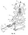
- FIG. 5Ais a perspective assembly view of a tissue puncture closure device with an automatic tamping or driving mechanism according to one embodiment of the present invention.
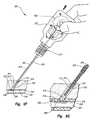
- FIG. 5Bis a side view of the tissue closure device of FIG. 5A inserted through a procedure sheath and shown engaged with an artery in a first position according to one embodiment of the present invention.
- FIG. 5Cis a detailed inset of FIG. 5B .
- FIG. 5Dis a side view of the tissue closure device of FIG. 5A shown engaged with an artery in a second position and being retracted according to one embodiment of the present invention.
- FIG. 5Eis a detailed inset of FIG. 5D .
- FIG. 5Fis a side view of the tissue closure device of FIG. 5A shown engaged with an artery in a third position tamping a sealing plug according to one embodiment of the present invention.
- FIG. 5Gis a detailed inset of FIG. 5F .
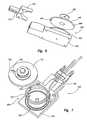
- FIG. 6is illustrates one embodiment of the driving mechanism of FIG. 5A in a bottom perspective assembly view according to the present invention.
- FIG. 7illustrates another embodiment of a driving mechanism in a top assembly view according to one embodiment of the present invention.
- FIG. 8illustrates another embodiment of a driving mechanism in a top assembly view according to one embodiment of the present invention.
- vascular proceduresare conducted throughout the world and require access to an artery through a puncture.
- the arteryis a femoral artery.
- a closure deviceis used to sandwich the puncture between an anchor and a sealing plug.
- the sealing plugis difficult to eject from the sealing device and may not properly seat against an exterior situs of the arteriotomy. If the plug does not seat properly against the arteriotomy, there is a potential for elongated bleeding.
- the present inventiondescribes methods and apparatus that facilitate sealing plug ejection and proper placement of the sealing plug. While the vascular instruments shown and described below include procedure sheaths and puncture sealing devices, the application of principles described herein are not limited to the specific devices shown. The principles described herein may be used with any medical device. Therefore, while the description below is directed primarily to arterial procedures and certain embodiments of a vascular closure device, the methods and apparatus are only limited by the appended claims.
- stampor “tamping” is used broadly to mean packing down by one or a succession of blows or taps or smooth, steady pressure, but not by excessive force.
- a “coil”is an object arranged in a curve, spiral, ring or winding capable of supporting a compressive load.
- a “spool”is a cylinder or other device on which something else is at least partially wound.
- a “tube”is an elongated device with a passageway. The passageway may be enclosed or open (e.g. a trough).
- a “lumen”refers to any open space or cavity in a bodily organ, especially in a blood vessel. “Slidingly mounted” means movable relative to an appropriate support.
- Free floatingmeans able to move freely according to at least one degree of freedom. “Free floating” movement is not necessarily unlimited, and may include free movement only within a specified range. “Transduce” means to convert a force or other input energy in one form into output energy or forces of another form or direction. The term “effecting” means producing an outcome, achieving a result, or bringing about.
- the vascular puncture closure device 100includes a carrier tube 102 with a filament or suture 104 extending at least partially therethrough.
- the closure device 100also includes a first or proximal end 106 and a second or distal end 107 .
- External to a second or distal end 107 of the carrier tube 102is an anchor 108 .
- the anchoris an elongated, stiff, low profile member including an eye 109 formed at the middle.
- the anchor 108is typically made of a biologically resorbable polymer.
- the suture 104is threaded through the anchor 108 and back to a collagen pad 110 .
- the collagen pad 110may be comprised of randomly oriented fibrous material bound together by chemical means.
- the collagen pad 110is slidingly attached to the suture 104 as the suture passes distally through the carrier tube 102 , but as the suture traverses the anchor 108 and reenters the carrier tube 102 , it is securely slip knotted proximal to the collagen pad 110 to facilitate cinching of the collagen pad 110 when the closure device 100 is properly placed and the anchor 108 deployed (see FIG. 4 ).
- the carrier tube 102typically includes a tamping tube 112 disposed therein.
- the tamping tube 112is slidingly mounted on the suture 104 and may be used by an operator to tamp the collagen pad 110 toward the anchor 108 at an appropriate time to seal a percutaneous tissue puncture.
- the eye 109 of the anchor 108rests outside the distal end 107 of the carrier tube 102 .
- the anchor 108may be temporarily held in place flush with the carrier tube 102 by a bypass tube 114 disposed over the distal end 107 of the carrier tube 102 .
- the flush arrangement of the anchor 108 and carrier tube 102allows the anchor 108 to be inserted into a procedure sheath such as insertion sheath 116 as shown in FIGS. 2-4 , and eventually through an arterial puncture 118 .
- the insertion sheath 116is shown in FIGS. 2-4 inserted through a percutaneous incision 119 and into an artery 128 .
- the bypass tube 114FIG. 1
- the bypass tube 114( FIG. 1 ) includes an oversized head 120 that prevents the bypass tube 114 from passing through an internal passage of the insertion sheath 116 . Therefore, as the puncture closure device 100 is inserted into the insertion sheath 116 , the oversized head 120 bears against a surface 122 of insertion sheath 116 .
- the insertion sheath 116includes a monofold 124 at a second or distal end 126 thereof.
- the monofold 124acts as a one-way valve to the anchor 108 .
- the monofold 124is a plastic deformation in a portion of the insertion sheath 116 that elastically flexes as the anchor 108 is pushed out through the distal end 126 of the insertion sheath 116 .
- the anchor 108is no longer constrained to the flush arrangement with respect to the carrier tube 102 and it deploys and rotates to the position shown in FIG. 2 .
- the puncture closure device 100 and the insertion sheath 116are withdrawn together, ejecting the collagen pad 110 from the carrier tube 102 into the incision tract 119 and exposing the tamping tube 112 .
- the collagen pad 110is manually tamped, and the anchor 108 and collagen pad 110 are cinched together and held in place with the self-tightening slip-knot on the suture 102 .
- the tissue punctureis sandwiched between the anchor 108 and the collagen pad 110 , thereby sealing the tissue puncture 118 .
- the suture 104is then cut and the incision tract 119 may be closed.
- the suture 104 , anchor 108 , and collagen pad 110are generally made of resorbable materials and therefore remain in place while the puncture 118 heals.
- the present specificationdescribes an apparatus such as a tissue puncture closure device that is capable of automatically tamping the sealing plug upon withdrawal of the tissue puncture closure device from the tissue puncture site.
- the mechanism for automatically driving the sealing plugmay comprise a coil operatively connected to the sealing plug, and the mechanism may be selectably disengagable.
- tissue closure devicesused for sealing a tissue puncture in an internal tissue wall accessible through an incision in the skin are well known in the art.
- Applications of closure devices including those implementing principles described hereininclude closure of a percutaneous puncture or incision in tissue separating two internal portions of a living body, such as punctures or incisions in blood vessels, ducts or lumens, gall bladders, livers, hearts, etc.
- FIGS. 5A-5Gan apparatus, for example a tissue wall puncture closure device 200 , is shown according to one embodiment of the present invention.
- the closure device 200is shown in an assembly view in FIG. 5A .
- FIGS. 5B-5Gillustrate the closure device 200 assembled and inserted through a procedure sheath 216 and into a lumen 232 .
- the closure device 200has particular utility when used in connection with intravascular procedures, such as angiographic dye injection, cardiac catheterization, balloon angioplasty and other types of recanalizing of atherosclerotic arteries, etc. as the closure device 200 is designed to cause immediate hemostasis of the blood vessel (e.g., arterial) puncture.
- the blood vessele.g., arterial
- the closure device 200includes a first or proximal end portion 206 and a second or distal end portion 207 .
- a carrier tube 202extends from the proximal end portion 206 to the distal end portion 207 and includes an outlet 213 at the distal end portion 207 .
- the distal end portion 207may include a slit 209 .
- the carrier tube 202may be made of plastic or other material and is designed for insertion through the procedure sheath 216 ( FIG. 5B ).
- the procedure sheath 216( FIG. 5B ) is designed for insertion through a percutaneous incision 219 ( FIG. 5B ) in a tissue layer 230 ( FIG. 5B ) and into the lumen 232 ( FIG. 5B ).
- the lumen 232comprises an interior portion of a femoral artery 228 .
- the anchor 208 of the present embodimentis an elongated, stiff, low-profile member arranged to be seated inside the artery 228 ( FIG. 5B ) against an artery wall 234 ( FIG. 5B ) contiguous with a puncture 218 ( FIG. 5B ).
- the anchor 208is preferably made of a biologically resorbable polymer.
- the sealing plug 210( FIG. 5B ) is formed of a compressible sponge, foam, or fibrous mat made of a non-hemostatic biologically resorbable material such as collagen, and may be configured in any shape so as to facilitate sealing the tissue puncture 218 ( FIG. 5B ).
- the sealing plug 210 and anchor 208are connected to one another by a connector such as a filament or suture 204 that is also biologically resorbable.
- the anchor 208 , the sealing plug 210 , and the suture 204are collectively referred to as the “closure elements” below.
- the anchor 208is initially arranged adjacent to and exterior of the distal end portion 207 of the carrier tube 202 , while the sealing plug 210 ( FIG. 5B ) is initially disposed within the carrier tube 202 .
- the anchor 208is shown nested in its low profile configuration along the carrier tube 202 to facilitate insertion into the lumen 232 ( FIG. 5B ) in FIG.
- the suture 204extends distally from the first end portion 206 of the closure device 200 through the carrier tube 202 .
- the suture 204may be threaded through one or more perforations in the sealing plug 210 , through a hole in the anchor 208 , and proximally back toward the carrier tube 202 to the sealing plug 210 .
- the suture 204is preferably threaded again through a perforation or series of perforations in the sealing plug 210 .
- the suture 204may also be threaded around itself to form a self-tightening slip-knot.
- the suture 204may thus connect the anchor 208 and the sealing plug 210 in a pulley-like arrangement to cinch the anchor 208 and the sealing plug 210 together when the carrier tube 202 is pulled away from the anchor 208 and the sealing plug 210 .
- the anchor 208 and the sealing plug 210sandwich and lock the anchor and plug together, sealing the tissue puncture 218 .
- the carrier tube 202may house a tamping device, such as a tamping tube 212 , for advancing the sealing plug 210 along the suture 204 and toward the anchor 208 .
- the tamping tube 212is shown located partially within the carrier tube 202 and proximal of the sealing plug 210 .
- the tamping tube 212also extends through a handle or housing 252 of the closure device 200 .
- the tamping tube 212is preferably an elongated tubular or semi-tubular member that may be rigid or flexible and formed of any suitable material.
- the tamping tube 212is made of polyurethane.
- the suture 204extends through at least a portion of the tamping tube 212 .
- the suture 204extends along the tamping tube 212 between the first and second end portions 206 , 207 .
- the suture 204is not directly connected to the tamping tube 212 . Accordingly, the suture 204 and the tamping tube 212 may slide past one another.
- the suture 204attaches to an automatic tamping assembly.
- the automatic tamping assemblymay include an automatic driving mechanism 630 or other transducer and the tamping tube 212 .
- the automatic driving mechanism 630is located within the housing or handle 252 at the first end portion 206 of the closure device 200 . Embodiments of the automatic driving mechanism 630 are described in detail below with reference to FIGS. 6-8 and may be selectively disengagable.
- the carrier tube 202 of the closure device 200(containing the closure elements described above) is inserted into the insertion sheath 216 , which is already inserted within the artery 228 ( FIGS. 5B-5C ).
- the anchor 208passes through and out of the distal end of the procedure sheath 216 and is inserted into the artery lumen 232 .
- the anchor 208is initially arranged substantially flush with the carrier tube 202 to facilitate insertion of the anchor 208 through the percutaneous incision 219 and into the lumen 232 .
- the closure device 200may also be partially withdrawn from the insertion sheath 216 , catching the anchor 208 on the distal end of the insertion sheath 216 and rotating it to the position shown in FIGS. 5B-5C .
- the closure device 200preferably includes a pair of biased fingers 215 that are lockingly received by a matching pair of recesses 217 in the procedure sheath 216 . The locking arrangement between the biased fingers 215 and matching recesses 217 may fix the position of the handle 252 relative to the procedure sheath 216 .
- the handle 252 and the insertion sheath 216are withdrawn together. Withdrawing the handle 252 causes the anchor 208 to anchor itself within the artery 228 against the artery wall 234 . With the anchor 208 anchored within the artery 228 at the puncture site 218 , further retraction of the handle 252 and insertion sheath 216 tends to pull the sealing plug 210 out from the distal end portion 207 of the carrier tube 202 , thereby depositing the plug 210 within the incision or puncture tract 219 .
- the slit 209 ( FIG. 5A ) in the carrier tube 202allows the distal end portion 207 of the carrier tube to flex or open, facilitating ejection of the sealing plug 210 .
- the distal end portion 207 of the carrier tube 202is exposed (within the incision tract 219 ) as the handle 252 and the procedure sheath 216 are retracted.
- the carrier tube 202may retain its position relative to the puncture 218 until the handle 252 and the procedure sheath 216 have been retracted a predetermined distance. Relative movement between the handle 252 /procedure sheath 216 and the carrier tube 202 may facilitated by a sliding mount arrangement between the automatic driving mechanism 630 and the handle 252 .
- the automatic driving mechanism 630is fixed to the handle 252 .
- the automatic driving mechanism 630(which is attached to the carrier tube 202 ) may be free floating or displaceable and slides relative to the handle 252 as the handle 252 and the procedure sheath 216 are retracted. However, the automatic driving mechanism 630 may be initially held in a first position relative to the handle 252 as shown in FIG. 5B .
- the automatic driving mechanism 630may comprise a temporary holder such as a stowage detent 255 slidingly mounted in a track.
- the trackis shown in FIG. 5B as a webbing track 253 .
- the webbing track 253is disposed in the handle 252 .
- the stowage detent 255may include a finger 257 with a protrusion to at least temporarily hold the automatic driving mechanism 630 in the first position shown in FIG. 5B , and prevent premature sliding within the handle 252 .
- the finger 257tends to hold or temporarily lock the automatic driving mechanism 630 in the first position shown in FIG. 5B , the finger 257 releases when a sufficient predetermined force is applied between the handle 252 and the automatic driving mechanism 630 .
- a retraction force provided by a user to the handle 252causes the finger 257 to deflect inward and release. Thereafter, the finger 257 provides very little resistance to sliding movement between the automatic driving mechanism 630 and the handle 252 .
- retraction of the handle 252may retract the procedure sheath 216 (which is fixedly connected to the handle 252 ), but the automatic driving mechanism 630 and the carrier tube 202 may slide relative to the handle 252 and therefore remain in position with respect to the puncture 218 as shown in FIG. 5D .
- the automatic driving mechanism 630may slide a predetermined distance with respect to the handle 252 until the automatic driving mechanism 630 reaches a stop. The predetermined distance may be at least long enough to fully expose the slit 209 ( FIG. 5A ) in the carrier tube 202 .
- the closure device 200 of the present inventionautomatically tamps the sealing plug 210 .
- the sealing plug 210may be tamped while the carrier tube 202 is being withdrawn, reducing or eliminating any gaps that may otherwise occur between the sealing plug 210 and the puncture 218 in the femoral artery 228 .
- the suture 204may cinch and lock (with a slip knot or the like) together the anchor 208 and the sealing plug 210 , sandwiching the artery wall 234 between the anchor 208 and sealing plug 210 .
- the force exerted by the tamping tube 212 and the cinching together of the anchor 208 and sealing plug 210 by the filament 204also causes the sealing plug 210 to deform radially outward within the puncture tract 219 and function as an anchor on the proximal side of the tissue puncture site 218 as shown in FIGS. 5F-5G .
- the tamping tube 212is automatically driven toward the sealing plug 210 by the automatic driving mechanism 630 .
- One embodiment of the automatic driving mechanism 630is shown in detail in FIGS. 5A and 6 .
- the automatic driving mechanism 630may comprise a coil assembly 629 and may be selectably disengageable. According to the embodiment of FIGS. 5A and 6 , once the automatic driving assembly 630 contacts the stop, further retraction of the closure device 200 automatically effects tamping of the sealing plug 210 (see FIGS. 5F-5G ).
- the coil assembly 629comprises a coil 633 having a first end 635 .
- the coil 633is operatively connected to the sealing plug 210 to automatically tamp the sealing plug 210 toward the anchor 208 .
- the coil 633may abut the tamping tube 212 , or the coil 633 may comprise the tamping tube 212 .
- the coil 633may be semi-flexible and is capable of taking the shape of a track and also providing a compression force to the sealing plug 210 .
- the coil assembly 629may further comprise a block such as plate block 634 that is disposed in the housing 252 .
- the plate block 634may comprise a generally planar first surface 636 that is receptive of a least a portion of the coil 633 .
- the plate block 634may thus include a channel such as a curved channel 638 shaped similarly to the coil 633 and may be recessed sufficiently to entirely receive the coil 633 .
- the curved channel 638may, however, exhibit a generally straight portion 639 as it leads out of the block 634 .
- the plate block 634may also comprise a protrusion 640 receptive of other components of the automatic driving mechanism 630 .
- the plate block 634may be receptive of a driving plate 642 .
- the driving plate 642may comprise a disk or circular shape as shown, although the driving plate 642 may include other shapes as well.
- the driving plate 642may be rotatably attached to the plate block 634 as shown.
- the driving plate 642includes a first generally planar surface 644 ( FIG. 5A ) and a second generally planar surface 646 ( FIG. 6 ).
- a drive pin 648extends laterally or normally from the second generally planar surface 646 . The radial position of the drive pin 648 corresponds to a radius of curvature of the curved channel 638 .
- the drive pin 648is rigidly fixed to or unitarily formed with the driving plate 642 .
- the drive pin 648extends into the curved channel 638 adjacent to the first end 635 of the coil 633 . Therefore, when the driving plate 642 rotates, the drive pin 648 engages or contacts the first end 635 of the coil 633 and provides a driving force to move a distal tip of the coil 633 along and out of the curved channel 638 .
- the coil 633is arranged adjacent to (or may even comprise) the tamping tube 212 , and therefore advancing the coil 633 by the drive pin 648 may effect tamping of the sealing plug 210 .
- the driving plate 642may be connected to a spool 632 .
- the suture 204is connected to and partially wound about the spool 632 .
- the driving plate 642tends to rotate at the same angular rate as the spool 632 , however, a clutch 650 may selectively connect and release the driving plate 642 from the spool 632 .
- a clutch 650may selectively connect and release the driving plate 642 from the spool 632 .
- One embodiment of the clutch 650is described in detail below, however, any clutch may be used.
- the spool 632rotates as the suture 204 unwinds and provides a torsional motive force that is transduced to a linear tamping force.
- the torsional motive force provided by the spool 632is transduced into the linear tamping force by the coil assembly 629 according to the embodiment of FIGS. 5A and 6 .
- the coil assembly 629includes the coil 633 and the driving plate 642 arranged coaxially with the spool 632 .
- the driving plate 642drives the driving plate 642 , which in turn drives the coil 633 .
- the coildrives the tamping tube 212 , which in turn tamps the sealing plug 210 .
- the tamping tube 212is preferably tubular or semi-tubular partially disposed about the suture 204 along its longitudinal axis. If the coil 633 also comprises the tamping tube, the coil 633 may comprise a semi-tubular shape having a generally U-shaped cross section, to provide a trough through which the suture 204 may enter and exit laterally. An open trough would permit the suture and the coil 633 to merge as the spool 632 unwinds. Accordingly, with the anchor 208 deployed, as the closure device 200 is retracted in a first direction, the suture 204 unwinds from the spool 632 , which drives the driving plate 642 . The driving plate 642 drives the coil 633 , and the coil 633 drives the tamping tube 212 in a second, opposite direction. The tamping tube tamps the sealing plug 210 .
- the clutch 650may comprise a plurality of release fingers 661 as shown in FIG. 5A .
- the release fingers 661are arranged substantially in a circle.
- a first component 663 of the release fingers 661is cantilevered from a base 637 and extends normal therefrom.
- a protrusion 665 of the first component 663extends radially outward and is received by a mating internal recess 667 of the spool 632 .
- a second component 669 of the release fingers 661arcs substantially normal to the first component 663 and the base 637 .
- the second component 669 of each of the release fingers 661extends through a central hole 671 of the spool 632 .
- An actuator button 651fits over and contacts the second components 669 of each of the release fingers 661 .
- the fit of the protrusions 665 of the base 637 with the mating recesses 667 of the spool 632causes the base 637 (and thus the driving plate 642 to which the base 637 is fixedly attached) and spool 632 to rotate together at an identical angular velocity.
- the actuator button 651when the actuator button 651 is depressed, the actuator button slides along the arcs of the second component 669 , forcing each of the release fingers 661 radially inward.
- the radial inward displacement of the release fingers 661at least partially removes the protrusions 665 from the mating recesses 667 , allowing independent rotation of the spool 632 with respect to the driving plate 642 .
- the selectably disengagable automatic driving mechanism 630is disengaged or disabled, allowing the suture 204 to safely unwind without further tamping. The suture 204 is then exposed to the operator for convenient cutting.
- the block 634may also be receptive of a closing mold 670 .
- the closing mold 670matingly fits over the block 634 and provides a suture and coil path 672 therethrough leading to the carrier tube 202 .
- FIG. 7Another embodiment of the automatic driving mechanism 630 is illustrated in FIG. 7 .
- the automatic driving mechanism 630 of FIG. 7may replace the mechanism 630 of FIG. 5A .
- the automatic driving mechanism 630 of FIG. 7is similar to the embodiment of FIG. 5A , however, the coil assembly 629 of FIG. 7 comprises a spiral shaped coil 733 .
- the spiral shaped coil 733is operatively connected to the sealing plug 210 ( FIG. 5A ) to automatically tamp the sealing plug 210 ( FIG. 5A ) toward the anchor 208 ( FIG. 5 ).
- block 734may comprise a spiral channel 738 shaped like the spiral shaped coil 733 .
- the spiral channel 738may, however, exhibit a generally straight portion 739 as it leads out of the block 734 .
- Driving plate 742may be rotatably attached to the block 734 .
- the driving plate 742comprises, however, a radial slot 754 in which a sliding drive pin 748 rides.
- the sliding drive pin 748extends normally from the driving plate 742 and into the spiral channel 738 at a first end 635 of the spiral coil 733 .
- the sliding drive pin 748is radially free floating in the slot 754 , and it is angularly stable.
- the sliding drive pin 748advances the spiral coil 733 along the spiral channel 738 , and the sliding drive pin 748 slides radially to remain in the spiral channel 738 while continuing to advance the spiral coil 733 .
- the spiral coil 733effects tamping of the sealing plug 210 ( FIG. 5A ).
- the remaining components of the automatic driving mechanism 630may be similar or identical to the embodiment of FIG. 5A .
- FIG. 8Another embodiment of an automatic driving mechanism 630 is illustrated in FIG. 8 .
- the automatic driving mechanism 630 of FIG. 8may replace the mechanism 630 of FIG. 5A .
- the automatic driving mechanism 630 of FIG. 8is similar to the embodiment of FIG. 7 , however, the coil assembly 629 of FIG. 8 comprises a disk such as a compliant plate 870 .
- the compliant plate 870is fixed to the driving plate 742 , but may also be clutched thereto with a spiral connection 880 .
- the compliant plate 870comprises an open slit 872 of variable width and a cantilevered finger 850 coplanar with the compliant plate 870 and extending along the open slit 872 .
- the cantilevered finger 850is radially flexible within the open slit 872 and includes a lateral drive pin 848 at a distal end thereof.
- the drive pin 848is thus free to move radially within the open slit 872 , and it is angularly stable. Therefore, as the driving plate 742 rotates, it drives the compliant plate 870 , and the compliant plate 870 comprising the drive pin 848 advances the spiral coil 733 along the spiral channel 738 .
- the drive pin 848moves radially as the compliant plate 870 rotates to remain in the spiral channel 738 while continuing to advance the spiral coil 733 , and the spiral coil 733 effects tamping of the sealing plug 210 ( FIG. 5A ).
- the compliant plate 870also comprises a driving plate and the driving plate 742 may be omitted.
- the remaining components of the automatic driving mechanism 630may be similar or identical to the embodiment of FIG. 5A .
- FIGS. 5A , 6 , 7 , and 8are exemplary in nature, and not limiting. Any configuration may be used to advance a coil within a channel to provide an automatic driving force to the sealing plug 210 ( FIG. 5F ).
- FIGS. 5A-8Operation of the embodiment of FIGS. 5A-8 is as follows. As the handle 252 of the closing device 200 is retracted from the puncture tract 219 as shown in FIG. 5B , the detent 255 releases. The automatic tamping mechanism 630 and carrier tube 202 may remain stationary and therefore float relative to the handle 252 . The procedure sheath 216 is retracted as the handle 252 is withdrawn, exposing the distal end 207 of the carrier tube 202 . The automatic tamping mechanism 630 eventually contacts a stop (or, in some embodiments, the automatic tamping mechanism is fixed), and further retraction causes the automatic tamping mechanism 630 and carrier tube 202 to retract as well.
- the suture 204which is threaded through the anchor 208 , unwinds from and causes rotation of the spool 632 .
- the spool 632drives the driving plate 642 / 742 or the compliant plate 870 as it rotates via a coaxial connection between.
- the coil 633 / 733is advanced along the channel 638 / 738 .
- the coil 633 / 733drives the tamping tube 212 , or the coil 633 / 733 may be long enough to operate as a tamping tube itself.
- the tamping tube 212tamps the sealing plug 210 .
- the drive pin 748 of the driving plate 742 or the drive pin 848 of compliant plate 870may migrate radially to remain in the spiral channel 738 and advance the coil 733 .
- the procedure sheath 216may be retracted ( FIGS. 5D-5E ), and the sealing plug 210 is automatically tamped ( FIGS. 5F-5G ).
- the sealing plug 210is more likely to create a sufficient arterial seal without a gap relative to the anchor 208 , as may otherwise occur with a separate manual tamping procedure.
- the automatic driving mechanism 630may be disengaged, enabling further retraction of the closure device 200 without additional tamping.
- the sealing plug 210fully tamped, there may be little or no portion of the suture 204 extending outside of the tissue layer 230 and exposed to an operator. Therefore, it may be difficult for an operator to separate the sealing plug 210 and anchor 208 from the remainder of the closure device 200 .
- too much retraction with the selectably automatic driving mechanism 630 enabledcould potentially overtamp the sealing plug 210 into the artery 228 . Accordingly, the automatic driving mechanism 630 may be advantageously disabled by activating the actuator 651 through the access hole 253 .
- Activating the actuator 651allows the suture 204 to fully unwind from the spool 632 without driving the tamping tube 212 . Unwinding the spool 632 exposes a sufficient length of the suture 204 to allow an operator to easily cut it and separate the sealing plug 210 and anchor 208 from the remainder of the closure device 200 .
Landscapes
- Health & Medical Sciences (AREA)
- Surgery (AREA)
- Life Sciences & Earth Sciences (AREA)
- Medical Informatics (AREA)
- Animal Behavior & Ethology (AREA)
- Engineering & Computer Science (AREA)
- Biomedical Technology (AREA)
- Heart & Thoracic Surgery (AREA)
- Veterinary Medicine (AREA)
- Molecular Biology (AREA)
- Nuclear Medicine, Radiotherapy & Molecular Imaging (AREA)
- General Health & Medical Sciences (AREA)
- Public Health (AREA)
- Rheumatology (AREA)
- Cardiology (AREA)
- Surgical Instruments (AREA)
- Pipe Accessories (AREA)
Abstract
Description
Claims (19)
Priority Applications (9)
| Application Number | Priority Date | Filing Date | Title |
|---|---|---|---|
| US11/197,382US7749247B2 (en) | 2005-08-04 | 2005-08-04 | Tissue puncture closure device with coiled automatic tamping system |
| AU2006279137AAU2006279137B2 (en) | 2005-08-04 | 2006-07-14 | Tissue puncture closure device with coiled automatic tamping system |
| AT06787426TATE529049T1 (en) | 2005-08-04 | 2006-07-14 | TISSUE PUNCTURE CLOSURE DEVICE WITH ROLLED AUTOMATIC TAMPING SYSTEM |
| CA002617173ACA2617173A1 (en) | 2005-08-04 | 2006-07-14 | Tissue puncture closure device with coiled automatic tamping system |
| ES06787426TES2375790T3 (en) | 2005-08-04 | 2006-07-14 | TISSULAR PUNCTURE CLOSURE DEVICE WITH SPIRAL AUTOMATIC COMPRESSION SYSTEM. |
| JP2008524984AJP5205263B2 (en) | 2005-08-04 | 2006-07-14 | Tissue puncture closure device with coiled automatic tamping system |
| PL06787426TPL1919367T3 (en) | 2005-08-04 | 2006-07-14 | Tissue puncture closure device with coiled automatic tamping system |
| EP06787426AEP1919367B1 (en) | 2005-08-04 | 2006-07-14 | Tissue puncture closure device with coiled automatic tamping system |
| PCT/US2006/027514WO2007018973A2 (en) | 2005-08-04 | 2006-07-14 | Tissue puncture closure device with coiled automatic tamping system |
Applications Claiming Priority (1)
| Application Number | Priority Date | Filing Date | Title |
|---|---|---|---|
| US11/197,382US7749247B2 (en) | 2005-08-04 | 2005-08-04 | Tissue puncture closure device with coiled automatic tamping system |
Publications (2)
| Publication Number | Publication Date |
|---|---|
| US20070032823A1 US20070032823A1 (en) | 2007-02-08 |
| US7749247B2true US7749247B2 (en) | 2010-07-06 |
Family
ID=37718533
Family Applications (1)
| Application Number | Title | Priority Date | Filing Date |
|---|---|---|---|
| US11/197,382Active2029-01-05US7749247B2 (en) | 2005-08-04 | 2005-08-04 | Tissue puncture closure device with coiled automatic tamping system |
Country Status (9)
| Country | Link |
|---|---|
| US (1) | US7749247B2 (en) |
| EP (1) | EP1919367B1 (en) |
| JP (1) | JP5205263B2 (en) |
| AT (1) | ATE529049T1 (en) |
| AU (1) | AU2006279137B2 (en) |
| CA (1) | CA2617173A1 (en) |
| ES (1) | ES2375790T3 (en) |
| PL (1) | PL1919367T3 (en) |
| WO (1) | WO2007018973A2 (en) |
Cited By (10)
| Publication number | Priority date | Publication date | Assignee | Title |
|---|---|---|---|---|
| US20100286727A1 (en)* | 2009-05-05 | 2010-11-11 | St. Jude Medical Puerto Rico Llc | Tissue puncture closure device with actuatable automatic spool driven compaction system |
| US8225674B2 (en)* | 2010-07-07 | 2012-07-24 | Cheng Uei Precision Industry Co., Ltd. | Tensile testing device |
| US8529598B2 (en) | 2009-02-20 | 2013-09-10 | Boston Scientific Scimed, Inc. | Tissue puncture closure device |
| US8758402B2 (en) | 2010-12-17 | 2014-06-24 | Boston Scientific Scimed, Inc. | Tissue puncture closure device |
| US8974476B2 (en) | 2011-03-23 | 2015-03-10 | St. Jude Medical Puerto Rico Llc | Vascular closure device with compaction tube suture cutting port and methods |
| US9022976B2 (en) | 2012-10-30 | 2015-05-05 | St. Jude Medical, Atrial Fibrillation Division, Inc. | Push-coil steering mechanism |
| US9149264B2 (en) | 2010-10-08 | 2015-10-06 | St. Jude Medical Puerto Rico Llc | Cam driven compaction tube for vascular closure device |
| US9301740B2 (en) | 2010-02-11 | 2016-04-05 | Boston Scientific Scimed, Inc. | Automatic vascular closure deployment devices and methods |
| US10154835B2 (en) | 2013-05-09 | 2018-12-18 | Essential Medical, Inc. | Vascular closure device with conforming plug member |
| US12383246B2 (en) | 2020-10-12 | 2025-08-12 | Abbott Cardiovascular Systems, Inc. | Vessel closure device with improved safety and tract hemostasis |
Families Citing this family (142)
| Publication number | Priority date | Publication date | Assignee | Title |
|---|---|---|---|---|
| US8992567B1 (en) | 2001-04-24 | 2015-03-31 | Cardiovascular Technologies Inc. | Compressible, deformable, or deflectable tissue closure devices and method of manufacture |
| US20090143808A1 (en)* | 2001-04-24 | 2009-06-04 | Houser Russell A | Guided Tissue Cutting Device, Method of Use and Kits Therefor |
| US20080109030A1 (en)* | 2001-04-24 | 2008-05-08 | Houser Russell A | Arteriotomy closure devices and techniques |
| US8961541B2 (en)* | 2007-12-03 | 2015-02-24 | Cardio Vascular Technologies Inc. | Vascular closure devices, systems, and methods of use |
| US8118836B2 (en) | 2004-11-05 | 2012-02-21 | Biomet Sports Medicine, Llc | Method and apparatus for coupling soft tissue to a bone |
| US8361113B2 (en) | 2006-02-03 | 2013-01-29 | Biomet Sports Medicine, Llc | Method and apparatus for coupling soft tissue to a bone |
| US7749250B2 (en) | 2006-02-03 | 2010-07-06 | Biomet Sports Medicine, Llc | Soft tissue repair assembly and associated method |
| US9801708B2 (en) | 2004-11-05 | 2017-10-31 | Biomet Sports Medicine, Llc | Method and apparatus for coupling soft tissue to a bone |
| US8137382B2 (en) | 2004-11-05 | 2012-03-20 | Biomet Sports Medicine, Llc | Method and apparatus for coupling anatomical features |
| US7658751B2 (en) | 2006-09-29 | 2010-02-09 | Biomet Sports Medicine, Llc | Method for implanting soft tissue |
| US8298262B2 (en) | 2006-02-03 | 2012-10-30 | Biomet Sports Medicine, Llc | Method for tissue fixation |
| US8128658B2 (en) | 2004-11-05 | 2012-03-06 | Biomet Sports Medicine, Llc | Method and apparatus for coupling soft tissue to bone |
| US9017381B2 (en) | 2007-04-10 | 2015-04-28 | Biomet Sports Medicine, Llc | Adjustable knotless loops |
| US7909851B2 (en) | 2006-02-03 | 2011-03-22 | Biomet Sports Medicine, Llc | Soft tissue repair device and associated methods |
| US7905904B2 (en) | 2006-02-03 | 2011-03-15 | Biomet Sports Medicine, Llc | Soft tissue repair device and associated methods |
| US8088130B2 (en) | 2006-02-03 | 2012-01-03 | Biomet Sports Medicine, Llc | Method and apparatus for coupling soft tissue to a bone |
| US8303604B2 (en) | 2004-11-05 | 2012-11-06 | Biomet Sports Medicine, Llc | Soft tissue repair device and method |
| US8608797B2 (en) | 2005-03-17 | 2013-12-17 | Valtech Cardio Ltd. | Mitral valve treatment techniques |
| US8333777B2 (en) | 2005-04-22 | 2012-12-18 | Benvenue Medical, Inc. | Catheter-based tissue remodeling devices and methods |
| US7691127B2 (en)* | 2005-12-13 | 2010-04-06 | Cardiva Medical, Inc. | Drug eluting vascular closure devices and methods |
| US9179897B2 (en)* | 2005-12-13 | 2015-11-10 | Cardiva Medical, Inc. | Vascular closure devices and methods providing hemostatic enhancement |
| US10517587B2 (en) | 2006-02-03 | 2019-12-31 | Biomet Sports Medicine, Llc | Method and apparatus for forming a self-locking adjustable loop |
| US8652172B2 (en) | 2006-02-03 | 2014-02-18 | Biomet Sports Medicine, Llc | Flexible anchors for tissue fixation |
| US8597327B2 (en) | 2006-02-03 | 2013-12-03 | Biomet Manufacturing, Llc | Method and apparatus for sternal closure |
| US9468433B2 (en) | 2006-02-03 | 2016-10-18 | Biomet Sports Medicine, Llc | Method and apparatus for forming a self-locking adjustable loop |
| US8652171B2 (en) | 2006-02-03 | 2014-02-18 | Biomet Sports Medicine, Llc | Method and apparatus for soft tissue fixation |
| US8562645B2 (en) | 2006-09-29 | 2013-10-22 | Biomet Sports Medicine, Llc | Method and apparatus for forming a self-locking adjustable loop |
| US9538998B2 (en) | 2006-02-03 | 2017-01-10 | Biomet Sports Medicine, Llc | Method and apparatus for fracture fixation |
| US11259792B2 (en) | 2006-02-03 | 2022-03-01 | Biomet Sports Medicine, Llc | Method and apparatus for coupling anatomical features |
| US8801783B2 (en) | 2006-09-29 | 2014-08-12 | Biomet Sports Medicine, Llc | Prosthetic ligament system for knee joint |
| US9408599B2 (en) | 2006-02-03 | 2016-08-09 | Biomet Sports Medicine, Llc | Method and apparatus for coupling soft tissue to a bone |
| US8968364B2 (en) | 2006-02-03 | 2015-03-03 | Biomet Sports Medicine, Llc | Method and apparatus for fixation of an ACL graft |
| US11311287B2 (en) | 2006-02-03 | 2022-04-26 | Biomet Sports Medicine, Llc | Method for tissue fixation |
| US9078644B2 (en) | 2006-09-29 | 2015-07-14 | Biomet Sports Medicine, Llc | Fracture fixation device |
| US8562647B2 (en) | 2006-09-29 | 2013-10-22 | Biomet Sports Medicine, Llc | Method and apparatus for securing soft tissue to bone |
| US9149267B2 (en) | 2006-02-03 | 2015-10-06 | Biomet Sports Medicine, Llc | Method and apparatus for coupling soft tissue to a bone |
| US8672969B2 (en) | 2006-09-29 | 2014-03-18 | Biomet Sports Medicine, Llc | Fracture fixation device |
| US8500818B2 (en) | 2006-09-29 | 2013-08-06 | Biomet Manufacturing, Llc | Knee prosthesis assembly with ligament link |
| US11259794B2 (en) | 2006-09-29 | 2022-03-01 | Biomet Sports Medicine, Llc | Method for implanting soft tissue |
| US9918826B2 (en) | 2006-09-29 | 2018-03-20 | Biomet Sports Medicine, Llc | Scaffold for spring ligament repair |
| US9883943B2 (en) | 2006-12-05 | 2018-02-06 | Valtech Cardio, Ltd. | Implantation of repair devices in the heart |
| US11259924B2 (en) | 2006-12-05 | 2022-03-01 | Valtech Cardio Ltd. | Implantation of repair devices in the heart |
| US11660190B2 (en) | 2007-03-13 | 2023-05-30 | Edwards Lifesciences Corporation | Tissue anchors, systems and methods, and devices |
| US8172871B2 (en)* | 2007-08-31 | 2012-05-08 | Ken Christopher G M | Closure medical device |
| US9456816B2 (en) | 2007-09-12 | 2016-10-04 | Transluminal Technologies, Llc | Closure device, deployment apparatus, and method of deploying a closure device |
| JP5426553B2 (en) | 2007-09-12 | 2014-02-26 | トランスルミナル テクノロジーズ リミテッド ライアビリティー カンパニー | Closure device, placement device, and method of placing a closure device |
| US8876861B2 (en)* | 2007-09-12 | 2014-11-04 | Transluminal Technologies, Inc. | Closure device, deployment apparatus, and method of deploying a closure device |
| AU2008318560B2 (en) | 2007-10-31 | 2014-12-04 | Cardinal Health 529, Llc | Method of making a vascular closure device |
| US8652166B2 (en) | 2007-11-30 | 2014-02-18 | Radi Medical Systems Ab | Insertion tool for a medical closure device |
| US8382829B1 (en) | 2008-03-10 | 2013-02-26 | Mitralign, Inc. | Method to reduce mitral regurgitation by cinching the commissure of the mitral valve |
| US9271706B2 (en)* | 2008-08-12 | 2016-03-01 | Covidien Lp | Medical device for wound closure and method of use |
| US9943302B2 (en) | 2008-08-12 | 2018-04-17 | Covidien Lp | Medical device for wound closure and method of use |
| US12245759B2 (en) | 2008-08-22 | 2025-03-11 | Biomet Sports Medicine, Llc | Method and apparatus for coupling soft tissue to bone |
| US12419632B2 (en) | 2008-08-22 | 2025-09-23 | Biomet Sports Medicine, Llc | Method and apparatus for coupling anatomical features |
| US8480686B2 (en)* | 2008-09-25 | 2013-07-09 | Ethicon Endo-Surgery, Inc. | Methods and devices for delivering and applying suture anchors |
| US9089320B2 (en)* | 2008-09-25 | 2015-07-28 | Ethicon Endo-Surgery, Inc. | Methods and devices for delivering and applying multiple suture anchors |
| US8262675B2 (en)* | 2008-10-29 | 2012-09-11 | Ethicon Endo-Surgery, Inc. | Methods and devices for applying multiple suture anchors |
| WO2010056915A1 (en)* | 2008-11-12 | 2010-05-20 | Accessclosure, Inc. | Apparatus and methods for sealing a vascular puncture |
| US8241351B2 (en) | 2008-12-22 | 2012-08-14 | Valtech Cardio, Ltd. | Adjustable partial annuloplasty ring and mechanism therefor |
| WO2010073246A2 (en) | 2008-12-22 | 2010-07-01 | Valtech Cardio, Ltd. | Adjustable annuloplasty devices and adjustment mechanisms therefor |
| US10517719B2 (en) | 2008-12-22 | 2019-12-31 | Valtech Cardio, Ltd. | Implantation of repair devices in the heart |
| US8911494B2 (en) | 2009-05-04 | 2014-12-16 | Valtech Cardio, Ltd. | Deployment techniques for annuloplasty ring |
| US8715342B2 (en) | 2009-05-07 | 2014-05-06 | Valtech Cardio, Ltd. | Annuloplasty ring with intra-ring anchoring |
| EP3181074A1 (en) | 2009-01-30 | 2017-06-21 | St. Jude Medical, Inc. | Transapical mini-introducer homeostasis valve and punch |
| US9839415B2 (en)* | 2009-01-30 | 2017-12-12 | St. Jude Medical, Llc | Apex closure device |
| US8353956B2 (en) | 2009-02-17 | 2013-01-15 | Valtech Cardio, Ltd. | Actively-engageable movement-restriction mechanism for use with an annuloplasty structure |
| US8052914B2 (en)* | 2009-02-20 | 2011-11-08 | Boston Scientific Scimed, Inc. | Modified plug for arteriotomy closure |
| US8375553B2 (en) | 2009-02-20 | 2013-02-19 | Boston Scientific Scimed, Inc. | Locking element for vascular closure device |
| US8317824B2 (en)* | 2009-02-20 | 2012-11-27 | Boston Scientific Scimed, Inc. | Tissue puncture closure device |
| US8292918B2 (en) | 2009-02-20 | 2012-10-23 | Boston Scientific Scimed, Inc. | Composite plug for arteriotomy closure and method of use |
| US9913634B2 (en)* | 2009-02-20 | 2018-03-13 | Boston Scientific Scimed, Inc. | Locking element for vascular closure device |
| US20100217309A1 (en)* | 2009-02-20 | 2010-08-26 | Boston Scientific Scimed, Inc. | Plug for arteriotomy closure and method of use |
| EP2416711A4 (en) | 2009-04-09 | 2017-06-07 | Cardiovascular Technologies, Inc. | Tissue closure devices, device and systems for delivery, kits and methods therefor |
| US9968452B2 (en) | 2009-05-04 | 2018-05-15 | Valtech Cardio, Ltd. | Annuloplasty ring delivery cathethers |
| US12096928B2 (en) | 2009-05-29 | 2024-09-24 | Biomet Sports Medicine, Llc | Method and apparatus for coupling soft tissue to a bone |
| US10098737B2 (en) | 2009-10-29 | 2018-10-16 | Valtech Cardio, Ltd. | Tissue anchor for annuloplasty device |
| US9180007B2 (en) | 2009-10-29 | 2015-11-10 | Valtech Cardio, Ltd. | Apparatus and method for guide-wire based advancement of an adjustable implant |
| JP5744893B2 (en) | 2009-11-09 | 2015-07-08 | アントラージュ メディカル テクノロジーズ,インコーポレイテッドEntourage Medical Technologies,Inc. | Systems that provide access and closure to the organization |
| US8734467B2 (en) | 2009-12-02 | 2014-05-27 | Valtech Cardio, Ltd. | Delivery tool for implantation of spool assembly coupled to a helical anchor |
| US9855031B2 (en) | 2010-04-13 | 2018-01-02 | Neosurgical Limited | Suture delivery system |
| GB2486497B (en) | 2010-12-17 | 2013-06-19 | Neosurgical Ltd | Laparoscopic trocar system |
| US9044267B2 (en) | 2010-06-11 | 2015-06-02 | Entourage Medical Technologies, Inc. | System and method for transapical access and closure |
| JP6300524B2 (en) | 2010-07-12 | 2018-03-28 | テルモ プエルトリコ エルエルシー | Tissue puncture closure device that does not require consolidation |
| EP2605707B1 (en)* | 2010-08-20 | 2014-10-08 | St. Jude Medical Puerto Rico LLC | Clutch release mechanism for vascular closure device |
| US9364207B2 (en)* | 2010-08-30 | 2016-06-14 | St. Jude Medical Puerto Rico Llc | Disengagable cam system for tissue puncture closure device |
| US8597340B2 (en) | 2010-09-17 | 2013-12-03 | Boston Scientific Scimed, Inc. | Torque mechanism actuated bioabsorbable vascular closure device |
| US9730690B2 (en)* | 2010-09-20 | 2017-08-15 | Entourage Medical Technologies, Inc. | Method for providing surgical access |
| AU2011326525B2 (en) | 2010-11-09 | 2015-06-18 | Transluminal Technologies, Llc | Specially designed magnesium-aluminum alloys and medical uses thereof in a hemodynamic environment |
| US20120143249A1 (en)* | 2010-12-03 | 2012-06-07 | Boston Scientific Scimed, Inc. | Closure device |
| US12329373B2 (en) | 2011-05-02 | 2025-06-17 | Biomet Sports Medicine, Llc | Method and apparatus for soft tissue fixation |
| US9895144B2 (en)* | 2011-06-07 | 2018-02-20 | Terumo Puerto Rico, L.L.C. | Circumferentially located suture release mechanism for vascular closure device |
| US10792152B2 (en) | 2011-06-23 | 2020-10-06 | Valtech Cardio, Ltd. | Closed band for percutaneous annuloplasty |
| EP3345573B1 (en) | 2011-06-23 | 2020-01-29 | Valtech Cardio, Ltd. | Closure element for use with annuloplasty structure |
| US10485524B2 (en) | 2011-10-25 | 2019-11-26 | Essential Medical, Inc. | Instrument and methods for surgically closing percutaneous punctures |
| US9357991B2 (en) | 2011-11-03 | 2016-06-07 | Biomet Sports Medicine, Llc | Method and apparatus for stitching tendons |
| US8858623B2 (en) | 2011-11-04 | 2014-10-14 | Valtech Cardio, Ltd. | Implant having multiple rotational assemblies |
| EP3656434B1 (en) | 2011-11-08 | 2021-10-20 | Valtech Cardio, Ltd. | Controlled steering functionality for implant-delivery tool |
| US9381013B2 (en) | 2011-11-10 | 2016-07-05 | Biomet Sports Medicine, Llc | Method for coupling soft tissue to a bone |
| US9314241B2 (en) | 2011-11-10 | 2016-04-19 | Biomet Sports Medicine, Llc | Apparatus for coupling soft tissue to a bone |
| EP2881083B1 (en) | 2011-12-12 | 2017-03-22 | David Alon | Heart valve repair device |
| US9757104B2 (en) | 2012-07-19 | 2017-09-12 | Essential Medical, Inc. | Multi-lumen tamper tube |
| US9216018B2 (en) | 2012-09-29 | 2015-12-22 | Mitralign, Inc. | Plication lock delivery system and method of use thereof |
| WO2014064694A2 (en) | 2012-10-23 | 2014-05-01 | Valtech Cardio, Ltd. | Controlled steering functionality for implant-delivery tool |
| EP2911593B1 (en) | 2012-10-23 | 2020-03-25 | Valtech Cardio, Ltd. | Percutaneous tissue anchor techniques |
| WO2014087402A1 (en) | 2012-12-06 | 2014-06-12 | Valtech Cardio, Ltd. | Techniques for guide-wire based advancement of a tool |
| US9131932B2 (en)* | 2013-02-01 | 2015-09-15 | St. Jude Medical Puerto Rico Llc | Dual lumen carrier tube with retractable sleeve and methods |
| EP2961351B1 (en) | 2013-02-26 | 2018-11-28 | Mitralign, Inc. | Devices for percutaneous tricuspid valve repair |
| US9757119B2 (en) | 2013-03-08 | 2017-09-12 | Biomet Sports Medicine, Llc | Visual aid for identifying suture limbs arthroscopically |
| US10449333B2 (en) | 2013-03-14 | 2019-10-22 | Valtech Cardio, Ltd. | Guidewire feeder |
| US9918827B2 (en) | 2013-03-14 | 2018-03-20 | Biomet Sports Medicine, Llc | Scaffold for spring ligament repair |
| CN105283214B (en) | 2013-03-15 | 2018-10-16 | 北京泰德制药股份有限公司 | Translate conduit, system and its application method |
| US10639019B2 (en) | 2013-03-15 | 2020-05-05 | Arrow International, Inc. | Vascular closure devices and methods of use |
| US10070857B2 (en) | 2013-08-31 | 2018-09-11 | Mitralign, Inc. | Devices and methods for locating and implanting tissue anchors at mitral valve commissure |
| WO2015059699A2 (en) | 2013-10-23 | 2015-04-30 | Valtech Cardio, Ltd. | Anchor magazine |
| AU2014342300A1 (en) | 2013-10-29 | 2016-05-19 | Entourage Medical Technologies, Inc. | System for providing surgical access |
| EP3858254B1 (en) | 2013-12-23 | 2024-04-24 | Teleflex Life Sciences LLC | Vascular closure device |
| US9610162B2 (en) | 2013-12-26 | 2017-04-04 | Valtech Cardio, Ltd. | Implantation of flexible implant |
| EP3922213A1 (en) | 2014-10-14 | 2021-12-15 | Valtech Cardio, Ltd. | Leaflet-restraining techniques |
| US20160256269A1 (en) | 2015-03-05 | 2016-09-08 | Mitralign, Inc. | Devices for treating paravalvular leakage and methods use thereof |
| CN107847320B (en) | 2015-04-30 | 2020-03-17 | 瓦尔泰克卡迪欧有限公司 | Valvuloplasty techniques |
| US10555727B2 (en) | 2015-06-26 | 2020-02-11 | Essential Medical, Inc. | Vascular closure device with removable guide member |
| US10828160B2 (en) | 2015-12-30 | 2020-11-10 | Edwards Lifesciences Corporation | System and method for reducing tricuspid regurgitation |
| US10702274B2 (en) | 2016-05-26 | 2020-07-07 | Edwards Lifesciences Corporation | Method and system for closing left atrial appendage |
| GB201611910D0 (en) | 2016-07-08 | 2016-08-24 | Valtech Cardio Ltd | Adjustable annuloplasty device with alternating peaks and troughs |
| CN106667554A (en)* | 2016-12-30 | 2017-05-17 | 西安中科微光影像技术有限公司 | System and method for safety adjustment of automatic puncture |
| US11045627B2 (en) | 2017-04-18 | 2021-06-29 | Edwards Lifesciences Corporation | Catheter system with linear actuation control mechanism |
| US10835221B2 (en) | 2017-11-02 | 2020-11-17 | Valtech Cardio, Ltd. | Implant-cinching devices and systems |
| US11135062B2 (en) | 2017-11-20 | 2021-10-05 | Valtech Cardio Ltd. | Cinching of dilated heart muscle |
| CN116531147A (en) | 2018-01-24 | 2023-08-04 | 爱德华兹生命科学创新(以色列)有限公司 | Contraction of annuloplasty structures |
| EP4248904A3 (en) | 2018-01-26 | 2023-11-29 | Edwards Lifesciences Innovation (Israel) Ltd. | Techniques for facilitating heart valve tethering and chord replacement |
| EP3820406B1 (en) | 2018-07-12 | 2023-12-20 | Edwards Lifesciences Innovation (Israel) Ltd. | Annuloplasty systems and locking tools therefor |
| SG11202112651QA (en) | 2019-05-29 | 2021-12-30 | Valtech Cardio Ltd | Tissue anchor handling systems and methods |
| US12364606B2 (en) | 2019-07-23 | 2025-07-22 | Edwards Lifesciences Innovation (Israel) Ltd. | Fluoroscopic visualization of heart valve anatomy |
| JP2022546160A (en) | 2019-08-30 | 2022-11-04 | エドワーズ ライフサイエンシーズ イノベーション (イスラエル) リミテッド | Anchor channel tip |
| EP4034042A1 (en) | 2019-09-25 | 2022-08-03 | Cardiac Implants LLC | Cardiac valve annulus reduction system |
| EP4193934A1 (en) | 2019-10-29 | 2023-06-14 | Edwards Lifesciences Innovation (Israel) Ltd. | Annuloplasty and tissue anchor technologies |
| US12023247B2 (en) | 2020-05-20 | 2024-07-02 | Edwards Lifesciences Corporation | Reducing the diameter of a cardiac valve annulus with independent control over each of the anchors that are launched into the annulus |
| CA3182316A1 (en) | 2020-06-19 | 2021-12-23 | Edwards Lifesciences Innovation (Israel) Ltd. | Self-stopping tissue anchors |
| US12390249B2 (en) | 2020-07-31 | 2025-08-19 | Teleflex Life Sciences Llc | Access sheath with valve assembly |
| WO2023150083A1 (en)* | 2022-02-02 | 2023-08-10 | Walters Greg A | Venous sealing apparatus and method of closing a venous access |
| CN118697404A (en)* | 2023-08-11 | 2024-09-27 | 上海拓脉医疗科技有限公司 | Vascular closure assembly and vascular closure device |
| CN119147810B (en)* | 2024-11-18 | 2025-04-18 | 无锡市恒通电器有限公司 | A Rogowski coil electric energy meter and its limiting mechanism |
Citations (27)
| Publication number | Priority date | Publication date | Assignee | Title |
|---|---|---|---|---|
| US4744364A (en) | 1987-02-17 | 1988-05-17 | Intravascular Surgical Instruments, Inc. | Device for sealing percutaneous puncture in a vessel |
| US4890612A (en) | 1987-02-17 | 1990-01-02 | Kensey Nash Corporation | Device for sealing percutaneous puncture in a vessel |
| US5021059A (en) | 1990-05-07 | 1991-06-04 | Kensey Nash Corporation | Plug device with pulley for sealing punctures in tissue and methods of use |
| US5222974A (en) | 1991-11-08 | 1993-06-29 | Kensey Nash Corporation | Hemostatic puncture closure system and method of use |
| US5282827A (en) | 1991-11-08 | 1994-02-01 | Kensey Nash Corporation | Hemostatic puncture closure system and method of use |
| US5290310A (en) | 1991-10-30 | 1994-03-01 | Howmedica, Inc. | Hemostatic implant introducer |
| US5411520A (en) | 1991-11-08 | 1995-05-02 | Kensey Nash Corporation | Hemostatic vessel puncture closure system utilizing a plug located within the puncture tract spaced from the vessel, and method of use |
| US5531759A (en)* | 1994-04-29 | 1996-07-02 | Kensey Nash Corporation | System for closing a percutaneous puncture formed by a trocar to prevent tissue at the puncture from herniating |
| US5545178A (en) | 1994-04-29 | 1996-08-13 | Kensey Nash Corporation | System for closing a percutaneous puncture formed by a trocar to prevent tissue at the puncture from herniating |
| US5662681A (en) | 1996-04-23 | 1997-09-02 | Kensey Nash Corporation | Self locking closure for sealing percutaneous punctures |
| US5779719A (en) | 1992-12-10 | 1998-07-14 | Perclose, Inc. | Device and method for the percutaneous suturing of a vascular puncture site |
| US5861004A (en) | 1991-11-08 | 1999-01-19 | Kensey Nash Corporation | Hemostatic puncture closure system including closure locking means and method of use |
| US5993467A (en)* | 1996-11-27 | 1999-11-30 | Yoon; Inbae | Suturing instrument with rotatably mounted spreadable needle holder |
| US6086607A (en) | 1998-05-01 | 2000-07-11 | Sub-Q, Inc. | Device and method for facilitating hemostasis of a biopsy tract |
| US6162192A (en) | 1998-05-01 | 2000-12-19 | Sub Q, Inc. | System and method for facilitating hemostasis of blood vessel punctures with absorbable sponge |
| WO2000078226A1 (en)* | 1999-06-18 | 2000-12-28 | Radi Medical Systems Ab | A tool, a sealing device, a system and a method for closing a wound |
| US6425911B1 (en) | 2001-05-09 | 2002-07-30 | Radi Medical Systems Ab | Positioning device and incision closure device |
| US20030060846A1 (en) | 2001-06-15 | 2003-03-27 | Radi Medical Systems Ab | Tamping mechanism |
| US20050085851A1 (en) | 2003-10-15 | 2005-04-21 | William Fiehler | Tissue puncture closure device with automatic tamping |
| US20060029674A1 (en)* | 2004-04-09 | 2006-02-09 | Sever Nancy E | Stable amorphous Cefdinir |
| US20060229673A1 (en)* | 2005-04-11 | 2006-10-12 | Forsberg Andrew T | Tissue puncture closure device with magazine fed tamping system |
| US7131979B2 (en)* | 2002-05-17 | 2006-11-07 | Dvl Acquisition Sub, Inc. | Surgical suturing instrument and method of use |
| US20060265006A1 (en)* | 2005-05-17 | 2006-11-23 | White John O | Tissue puncture closure device with disengagable automatic tamping system |
| US20060265007A1 (en)* | 2005-05-17 | 2006-11-23 | St. Jude Medical Puerto Rico B.V. | Tissue puncture closure system with retractable sheath |
| US7250057B2 (en)* | 2005-04-11 | 2007-07-31 | St. Jude Medical Puerto Rico B.V. | Tissue puncture closure device with automatic torque sensing tamping system |
| US20070255314A1 (en)* | 2005-04-11 | 2007-11-01 | St. Jude Medical Puerto Rico B.V. | Tissue puncture closure device with automatic torque sensing tamping system |
| US20080071311A1 (en)* | 2006-09-18 | 2008-03-20 | St. Jude Medical Puerto Rico B.V. | Flexible tamping device |
Family Cites Families (3)
| Publication number | Priority date | Publication date | Assignee | Title |
|---|---|---|---|---|
| FR2638718B1 (en)* | 1988-11-09 | 1991-02-15 | Oreal | DISPENSING HEAD FOR AN ADDITIVE, INTENDED TO BE MOUNTED ON A CONTAINER, AND CONTAINER PROVIDED WITH SUCH A DISPENSING HEAD |
| US5045569A (en)* | 1988-11-30 | 1991-09-03 | Minnesota Mining And Manufacturing Company | Hollow acrylate polymer microspheres |
| US20050096697A1 (en)* | 2003-11-04 | 2005-05-05 | Forsberg Andrew T. | Vascular insertion sheath with stiffened tip |
- 2005
- 2005-08-04USUS11/197,382patent/US7749247B2/enactiveActive
- 2006
- 2006-07-14EPEP06787426Apatent/EP1919367B1/enactiveActive
- 2006-07-14JPJP2008524984Apatent/JP5205263B2/enactiveActive
- 2006-07-14AUAU2006279137Apatent/AU2006279137B2/enactiveActive
- 2006-07-14ATAT06787426Tpatent/ATE529049T1/ennot_activeIP Right Cessation
- 2006-07-14ESES06787426Tpatent/ES2375790T3/enactiveActive
- 2006-07-14WOPCT/US2006/027514patent/WO2007018973A2/enactiveApplication Filing
- 2006-07-14PLPL06787426Tpatent/PL1919367T3/enunknown
- 2006-07-14CACA002617173Apatent/CA2617173A1/ennot_activeAbandoned
Patent Citations (32)
| Publication number | Priority date | Publication date | Assignee | Title |
|---|---|---|---|---|
| US4890612A (en) | 1987-02-17 | 1990-01-02 | Kensey Nash Corporation | Device for sealing percutaneous puncture in a vessel |
| US4744364A (en) | 1987-02-17 | 1988-05-17 | Intravascular Surgical Instruments, Inc. | Device for sealing percutaneous puncture in a vessel |
| US5021059A (en) | 1990-05-07 | 1991-06-04 | Kensey Nash Corporation | Plug device with pulley for sealing punctures in tissue and methods of use |
| US5290310A (en) | 1991-10-30 | 1994-03-01 | Howmedica, Inc. | Hemostatic implant introducer |
| US5411520A (en) | 1991-11-08 | 1995-05-02 | Kensey Nash Corporation | Hemostatic vessel puncture closure system utilizing a plug located within the puncture tract spaced from the vessel, and method of use |
| US5282827A (en) | 1991-11-08 | 1994-02-01 | Kensey Nash Corporation | Hemostatic puncture closure system and method of use |
| US5935147A (en) | 1991-11-08 | 1999-08-10 | Kensey Nash Corporation | Hemostatic puncture closure system and method of use |
| US5441517A (en) | 1991-11-08 | 1995-08-15 | Kensey Nash Corporation | Hemostatic puncture closure system and method of use |
| US5222974A (en) | 1991-11-08 | 1993-06-29 | Kensey Nash Corporation | Hemostatic puncture closure system and method of use |
| US6045569A (en) | 1991-11-08 | 2000-04-04 | Kensey Nash Corporation | Hemostatic puncture closure system including closure locking means and methods of use |
| US6007563A (en) | 1991-11-08 | 1999-12-28 | Kensey Nash Corporation | Method of deploying percutaneous puncture closure |
| US5707393A (en) | 1991-11-08 | 1998-01-13 | Kensey Nash Corporation | Hemostatic puncture closure system and method of use |
| US5861004A (en) | 1991-11-08 | 1999-01-19 | Kensey Nash Corporation | Hemostatic puncture closure system including closure locking means and method of use |
| US5779719A (en) | 1992-12-10 | 1998-07-14 | Perclose, Inc. | Device and method for the percutaneous suturing of a vascular puncture site |
| US5531759A (en)* | 1994-04-29 | 1996-07-02 | Kensey Nash Corporation | System for closing a percutaneous puncture formed by a trocar to prevent tissue at the puncture from herniating |
| US5545178A (en) | 1994-04-29 | 1996-08-13 | Kensey Nash Corporation | System for closing a percutaneous puncture formed by a trocar to prevent tissue at the puncture from herniating |
| US5662681A (en) | 1996-04-23 | 1997-09-02 | Kensey Nash Corporation | Self locking closure for sealing percutaneous punctures |
| US5993467A (en)* | 1996-11-27 | 1999-11-30 | Yoon; Inbae | Suturing instrument with rotatably mounted spreadable needle holder |
| US6086607A (en) | 1998-05-01 | 2000-07-11 | Sub-Q, Inc. | Device and method for facilitating hemostasis of a biopsy tract |
| US6162192A (en) | 1998-05-01 | 2000-12-19 | Sub Q, Inc. | System and method for facilitating hemostasis of blood vessel punctures with absorbable sponge |
| WO2000078226A1 (en)* | 1999-06-18 | 2000-12-28 | Radi Medical Systems Ab | A tool, a sealing device, a system and a method for closing a wound |
| US6425911B1 (en) | 2001-05-09 | 2002-07-30 | Radi Medical Systems Ab | Positioning device and incision closure device |
| US20030060846A1 (en) | 2001-06-15 | 2003-03-27 | Radi Medical Systems Ab | Tamping mechanism |
| US7131979B2 (en)* | 2002-05-17 | 2006-11-07 | Dvl Acquisition Sub, Inc. | Surgical suturing instrument and method of use |
| US20050085851A1 (en) | 2003-10-15 | 2005-04-21 | William Fiehler | Tissue puncture closure device with automatic tamping |
| US20060029674A1 (en)* | 2004-04-09 | 2006-02-09 | Sever Nancy E | Stable amorphous Cefdinir |
| US20060229673A1 (en)* | 2005-04-11 | 2006-10-12 | Forsberg Andrew T | Tissue puncture closure device with magazine fed tamping system |
| US7250057B2 (en)* | 2005-04-11 | 2007-07-31 | St. Jude Medical Puerto Rico B.V. | Tissue puncture closure device with automatic torque sensing tamping system |
| US20070255314A1 (en)* | 2005-04-11 | 2007-11-01 | St. Jude Medical Puerto Rico B.V. | Tissue puncture closure device with automatic torque sensing tamping system |
| US20060265006A1 (en)* | 2005-05-17 | 2006-11-23 | White John O | Tissue puncture closure device with disengagable automatic tamping system |
| US20060265007A1 (en)* | 2005-05-17 | 2006-11-23 | St. Jude Medical Puerto Rico B.V. | Tissue puncture closure system with retractable sheath |
| US20080071311A1 (en)* | 2006-09-18 | 2008-03-20 | St. Jude Medical Puerto Rico B.V. | Flexible tamping device |
Cited By (14)
| Publication number | Priority date | Publication date | Assignee | Title |
|---|---|---|---|---|
| US8529598B2 (en) | 2009-02-20 | 2013-09-10 | Boston Scientific Scimed, Inc. | Tissue puncture closure device |
| US9282955B2 (en) | 2009-02-20 | 2016-03-15 | Boston Scientific Scimed, Inc. | Tissue puncture closure device |
| US8465519B2 (en) | 2009-05-05 | 2013-06-18 | St. Jude Medical Puerto Rico Llc | Tissue puncture closure device with actuatable automatic spool driven compaction system |
| US20100286727A1 (en)* | 2009-05-05 | 2010-11-11 | St. Jude Medical Puerto Rico Llc | Tissue puncture closure device with actuatable automatic spool driven compaction system |
| US8298259B2 (en) | 2009-05-05 | 2012-10-30 | St. Jude Medical Puerto Rico Llc | Tissue puncture closure device with actuatable automatic spool driven compaction system |
| US9301740B2 (en) | 2010-02-11 | 2016-04-05 | Boston Scientific Scimed, Inc. | Automatic vascular closure deployment devices and methods |
| US8225674B2 (en)* | 2010-07-07 | 2012-07-24 | Cheng Uei Precision Industry Co., Ltd. | Tensile testing device |
| US9149264B2 (en) | 2010-10-08 | 2015-10-06 | St. Jude Medical Puerto Rico Llc | Cam driven compaction tube for vascular closure device |
| US8758402B2 (en) | 2010-12-17 | 2014-06-24 | Boston Scientific Scimed, Inc. | Tissue puncture closure device |
| US8974476B2 (en) | 2011-03-23 | 2015-03-10 | St. Jude Medical Puerto Rico Llc | Vascular closure device with compaction tube suture cutting port and methods |
| US9022976B2 (en) | 2012-10-30 | 2015-05-05 | St. Jude Medical, Atrial Fibrillation Division, Inc. | Push-coil steering mechanism |
| US10980977B2 (en) | 2012-10-30 | 2021-04-20 | St. Jude Medical, Atrial Fibrillation Division, Inc. | Push-coil steering mechanism |
| US10154835B2 (en) | 2013-05-09 | 2018-12-18 | Essential Medical, Inc. | Vascular closure device with conforming plug member |
| US12383246B2 (en) | 2020-10-12 | 2025-08-12 | Abbott Cardiovascular Systems, Inc. | Vessel closure device with improved safety and tract hemostasis |
Also Published As
| Publication number | Publication date |
|---|---|
| JP5205263B2 (en) | 2013-06-05 |
| ES2375790T3 (en) | 2012-03-06 |
| CA2617173A1 (en) | 2007-02-15 |
| WO2007018973A3 (en) | 2007-07-12 |
| AU2006279137B2 (en) | 2011-08-04 |
| AU2006279137A1 (en) | 2007-02-15 |
| PL1919367T3 (en) | 2012-07-31 |
| EP1919367A4 (en) | 2010-08-04 |
| ATE529049T1 (en) | 2011-11-15 |
| JP2009502419A (en) | 2009-01-29 |
| US20070032823A1 (en) | 2007-02-08 |
| WO2007018973A2 (en) | 2007-02-15 |
| EP1919367A2 (en) | 2008-05-14 |
| EP1919367B1 (en) | 2011-10-19 |
Similar Documents
| Publication | Publication Date | Title |
|---|---|---|
| US7749247B2 (en) | Tissue puncture closure device with coiled automatic tamping system | |
| US7837705B2 (en) | Tissue puncture closure system with retractable sheath | |
| US8591542B2 (en) | Tissue puncture closure method with disengagable automatic tamping system | |
| US9763652B2 (en) | Disengagable cam system for tissue puncture closure device and methods | |
| US9895144B2 (en) | Circumferentially located suture release mechanism for vascular closure device | |
| US9220489B2 (en) | Clutch release mechanism for vascular closure device | |
| EP2624763B1 (en) | Cam driven compaction tube for vascular closure device | |
| AU2012202872B2 (en) | Tissue puncture closure system with retractable sheath |
Legal Events
| Date | Code | Title | Description |
|---|---|---|---|
| AS | Assignment | Owner name:ST. JUDE MEDICAL PUERTO RICO B.V., NETHERLANDS Free format text:ASSIGNMENT OF ASSIGNORS INTEREST;ASSIGNOR:TEGG, TROY;REEL/FRAME:016823/0391 Effective date:20050728 | |
| AS | Assignment | Owner name:ST. JUDE MEDICAL PUERTO RICO LLC, PUERTO RICO Free format text:ACQUISITION;ASSIGNOR:ST. JUDE MEDICAL PUERTO RICO B.V.;REEL/FRAME:021998/0591 Effective date:20071228 Owner name:ST. JUDE MEDICAL PUERTO RICO LLC,PUERTO RICO Free format text:ACQUISITION;ASSIGNOR:ST. JUDE MEDICAL PUERTO RICO B.V.;REEL/FRAME:021998/0591 Effective date:20071228 | |
| STCF | Information on status: patent grant | Free format text:PATENTED CASE | |
| FPAY | Fee payment | Year of fee payment:4 | |
| AS | Assignment | Owner name:TERUMO PUERTO RICO, L.L.C., PUERTO RICO Free format text:ASSIGNMENT OF ASSIGNORS INTEREST;ASSIGNOR:ST. JUDE MEDICAL PUERTO RICO LLC;REEL/FRAME:041520/0883 Effective date:20170120 | |
| MAFP | Maintenance fee payment | Free format text:PAYMENT OF MAINTENANCE FEE, 8TH YEAR, LARGE ENTITY (ORIGINAL EVENT CODE: M1552) Year of fee payment:8 | |
| MAFP | Maintenance fee payment | Free format text:PAYMENT OF MAINTENANCE FEE, 12TH YEAR, LARGE ENTITY (ORIGINAL EVENT CODE: M1553); ENTITY STATUS OF PATENT OWNER: LARGE ENTITY Year of fee payment:12 |