US7749226B2 - Method for forming a tunnel in a bone - Google Patents
Method for forming a tunnel in a boneDownload PDFInfo
- Publication number
- US7749226B2 US7749226B2US11/526,173US52617306AUS7749226B2US 7749226 B2US7749226 B2US 7749226B2US 52617306 AUS52617306 AUS 52617306AUS 7749226 B2US7749226 B2US 7749226B2
- Authority
- US
- United States
- Prior art keywords
- tunnel
- drill guide
- forming device
- forming
- bone
- Prior art date
- Legal status (The legal status is an assumption and is not a legal conclusion. Google has not performed a legal analysis and makes no representation as to the accuracy of the status listed.)
- Active, expires
Links
- 210000000988bone and boneAnatomy0.000titleclaimsabstractdescription55
- 238000000034methodMethods0.000titleclaimsabstractdescription25
- 238000005553drillingMethods0.000claimsdescription12
- 210000003041ligamentAnatomy0.000description7
- 210000002303tibiaAnatomy0.000description4
- 210000000689upper legAnatomy0.000description4
- 230000007613environmental effectEffects0.000description3
- 210000003484anatomyAnatomy0.000description2
- 210000001264anterior cruciate ligamentAnatomy0.000description2
- 210000003127kneeAnatomy0.000description2
- 210000002967posterior cruciate ligamentAnatomy0.000description2
- 238000001356surgical procedureMethods0.000description2
- 235000014443Pyrus communisNutrition0.000description1
- 238000007796conventional methodMethods0.000description1
- 230000002452interceptive effectEffects0.000description1
- 238000012986modificationMethods0.000description1
- 230000004048modificationEffects0.000description1
- 238000007493shaping processMethods0.000description1
Images


Classifications
- A—HUMAN NECESSITIES
- A61—MEDICAL OR VETERINARY SCIENCE; HYGIENE
- A61B—DIAGNOSIS; SURGERY; IDENTIFICATION
- A61B17/00—Surgical instruments, devices or methods
- A61B17/16—Instruments for performing osteoclasis; Drills or chisels for bones; Trepans
- A61B17/17—Guides or aligning means for drills, mills, pins or wires
- A61B17/1714—Guides or aligning means for drills, mills, pins or wires for applying tendons or ligaments
- A—HUMAN NECESSITIES
- A61—MEDICAL OR VETERINARY SCIENCE; HYGIENE
- A61B—DIAGNOSIS; SURGERY; IDENTIFICATION
- A61B17/00—Surgical instruments, devices or methods
- A61B17/16—Instruments for performing osteoclasis; Drills or chisels for bones; Trepans
- A61B17/17—Guides or aligning means for drills, mills, pins or wires
- A61B17/1739—Guides or aligning means for drills, mills, pins or wires specially adapted for particular parts of the body
- A61B17/1764—Guides or aligning means for drills, mills, pins or wires specially adapted for particular parts of the body for the knee
Definitions
- femoral and tibial tunnelsare drilled for securing a graft ligament to the tibia and femur.
- Various drill guides or aimersare known for guiding a drilling device to form these tunnels.
- the present teachingsprovide a method for forming a tunnel in a bone.
- the methodincludes forming a first tunnel in the bone, the tunnel having a longitudinal axis, inserting a first drill guide into the first tunnel, supporting a first tunnel-forming device along an axis defining a first offset relative the longitudinal axis of the first tunnel with the first drill guide, and forming a second tunnel alongside the first tunnel with the first tunnel-forming device, the second tunnel communicating with the first tunnel and defining a single elongated opening.
- the present teachingsalso provide a method for forming a tunnel in a bone and includes forming a first tunnel in the bone, the first tunnel having a longitudinal axis, inserting into the first tunnel a first drill guide having a guiding bore with an axis defining a first offset relative to the longitudinal axis of the first tunnel, supporting a first tunnel-forming device on the first drill guide such that a longitudinal axis of the first tunnel-forming device coincides with the axis of the guiding bore and the first tunnel-forming device extends at least partially outside the first tunnel in a transverse direction relative to the longitudinal axis of the first tunnel, and drilling with the first tunnel-forming device a second tunnel parallel to and communicating with the first tunnel along the longitudinal direction.
- the present teachingsfurther provide a method for forming a tunnel in a bone.
- the methodincludes inserting a guide pin in the bone, positioning a cannulated tunnel-forming device over the guide pin, drilling with the cannulated tunnel-forming device a first tunnel in the bone, the first tunnel having a longitudinal axis, and removing the guide pin and the cannulated tunnel-forming device.
- the methodfurther includes inserting into the first tunnel a first drill guide having a guiding bore with an axis defining a first offset relative to the longitudinal axis of the first tunnel, supporting a first tunnel-forming device on the first drill guide such that a longitudinal axis of the first tunnel-forming device coincides with the axis of the guiding bore and the first tunnel-forming device extends at least partially outside the first tunnel in a transverse direction relative to the longitudinal axis of the first tunnel, and drilling with the first tunnel-forming device a second tunnel parallel to and communicating with the first tunnel along the longitudinal direction and in the direction of the offset, wherein the first and second tunnels define an elongated opening, the elongated opening being elongated in the direction of the first offset.
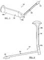
- FIG. 1is a perspective view of a drill guide device according to the present teachings
- FIG. 2is a side view of the drill guide device of FIG. 1 ;
- FIG. 3is front view of the drill guide device of FIG. 1 ;
- FIG. 4is another a perspective view of the drill guide device of FIG. 1 ;
- FIG. 5is a side perspective view of a drill guide device according to the present teachings, the drill guide device shown with a tunnel-forming device;
- FIG. 6is a front perspective view of the drill guide device of FIG. 5 ;
- FIG. 7is a sectional view of the drill guide device of FIG. 5 ;
- FIG. 8is a side perspective view of a drill guide device according to the present teachings, the drill guide device shown with a tunnel-forming device;
- FIG. 9is a front perspective view of the drill guide device of FIG. 8 ;
- FIG. 10is a sectional view of the drill guide device of FIG. 8 ;
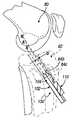
- FIG. 11is an environmental view showing a cannulated tunnel-forming device over a guide pin in a tibial tunnel;
- FIG. 12is an environmental view showing the drill guide device of FIG. 5 in a tibial tunnel
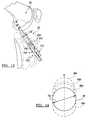
- FIG. 13is an environmental view showing the drill guide device of FIG. 8 in a tibial tunnel.
- FIG. 14is a view showing exemplary cross-sections of a bone tunnel formed according to the present teachings.
- the present teachingsare illustrated for cruciate ligament reconstruction in knee surgery, the present teachings can be used for re-shaping any tunnel in a long bone, including the tibia and femur.
- an exemplary drill guide device 100can be used to change the shape of an existing or first bone tunnel 84 during cruciate ligament reconstruction.
- the first bone tunnel 84can have substantially circular cross-section and can be initially drilled over a guide wire or a guide pin 140 in the tibia 82 or femur 80 by conventional methods using, for example, a cannulated tunnel-forming device 142 , as shown in FIG. 11 .
- the guide wire 140 and the cannulated tunnel-forming device 142can then be removed.
- the drill guide device 100can be used to change the shape of the cross-section of the first bone tunnel 84 from circular to oval, egg-shaped, pear-shaped, elongated, eight-shaped, or asymmetric in a desired orientation including the anterior, posterior, medial or lateral directions, or any other shape, as discussed below.
- the drill guide device 100can be used after such change in the shape of the first bone channel 84 is made to further change the new cross-section, as discussed below.
- the new shape of the first bone tunnel 84can be selected for providing a desired anatomic orientation, path/shape and placement of the ligament grafts, as determined by the surgeon.
- bone tunnels with elongated cross-sectionscan be used for accommodating several strands of ligament grafts, and can also be used to approximate the shape and path of the anterior or posterior cruciate ligaments.
- the elongated shapecan be made by drilling a new tunnel alongside and communicating with first bone tunnel 84 as illustrated in FIG. 14 , and discussed below.
- the drill guide device 100can include an arm 102 , a drill guide 104 extending from the arm 102 , and a support member 106 , which can be used to secure the drill guide device 110 to the bone and can also function as a handle.
- the support member 106can have first and second portions 106 a and 106 b .
- the arm 102can be supported either fixedly or removably on its proximal end on the first portion 106 a of the support member 106 at an angle of about 90-degrees for exerting axial force.
- the second portion 106 bcan be oriented at a different angle relative to the arm 102 , for ergonomic considerations and for avoiding the patient's anatomy.
- the arm 102can be in the form of a semi-cylindrical shaft having an open-channel cross-section 116 or as an incomplete/open tube, adapted for receiving and guiding a drill, any other drilling/reaming device, a trephine, or generally any tunnel-forming device 110 , such that a portion of the tunnel-forming device extends outside the cross-section 116 of the arm 102 to be exposed to form the tunnel.
- the drill guide 104can be bullet-shaped, and include a proximal portion 120 and a distal portion 114 , which is first inserted into the bone tunnel.
- the proximal portion 120can be cylindrical, and the distal portion 114 can be conical with a blunt closed tip 112 .
- the proximal portion 120can have a cross-section in the form of a complete circle, as shown in FIG. 4 , or can be a portion of a circle with an arc cut off as shown in FIG. 6 .
- the outer surface of the first portion 120can substantially conform to the shape of the first bone tunnel 84 . If the first bone tunnel 84 is circular, then the drill guide 100 can have a circular cross-section with a diameter that corresponds to the diameter of the bone tunnel 84 , such that the drill guide 104 can be inserted in the first bone tunnel 84 .
- the proximal and distal portions 120 , 114 of the drill guide 104are concentric and define a longitudinal axis A that substantially coincides with the bone tunnel axis when the drill guide 104 is inserted into the bone tunnel 84 , as illustrated in FIG. 12 .
- a tunnel-forming device having a longitudinal drill axis Bcan seat on an inner surface 122 of the arm 102 and be guided by the drill guide 104 , as shown in FIGS. 5 and 6 , such that the drill axis B is parallel and offset relative to the axis A by an offset distance D.
- the tunnel-forming devicecan include a distal shaft 111 , which can be received in an internal guiding bore 124 of the drill guide 104 .
- the guiding bore 124defines an axis B which coincides with the drill axis B.
- the offset Dallows the tunnel-forming device to extend the diameter TD of the bone tunnel 84 in a selected direction C to define a new cross-section that is elongated in the direction of the axis C, such as the exemplary cross-sectional shapes shown at 84 a , 84 b in FIG. 14 .
- the new cross-sectional shapecan be any shape with an elongated axis, including eight-shaped, oval, pear or egg-shaped and other elongated shapes with one or two axes of symmetry.
- the drill guide device 100can include a drill guide 104 that can be used with a second bone tunnel 84 b that has already been elongated in the direction C, as discussed above.
- the drill guide 104can have a cross-sectional shape 130 that corresponds to the elongated shape of the second tunnel 84 b , such that the drill guide 104 can be inserted in the second bone tunnel 84 b for elongating further the second bone tunnel 84 b to a third bone tunnel 84 c with a new shape.
- the drill guide 104can include first and second distal portions 114 arranged one above the other and having corresponding longitudinal axes A and A′, as shown in FIG. 9 .
- the first and second distal portions 114can be made as single unitary part of the drill guide or can be separate, but modularly connected portions.
- a guiding bore 124 in the drill guide 104defines an axis B′ which coincides with the drill axis and is offset from the second axis A′ by an offset distance D.
- the offset distance Dcan have many different values and is not necessarily equal to the offset distance D between axes A and B shown in FIG. 7 .
- the additional elongation of the tunnel 84 b to a new tunnel 84 ccan be provided in the same, opposite or other different direction than the direction of the initial elongation, as shown, for example, in FIG. 14 , which illustrated two elongations 84 c in opposite directions relative to the first bone tunnel 84 .
- a first drill guide 104 with a single drill guide axis Ais inserted in a first bone tunnel 84 of circular cross-section, which was formed, for example, as discussed above in connection with FIG. 11 .
- the first drill guide 104can align a first tunnel-forming device along an axis B parallel and offset by a distance D from the drill guide axis A, such that the first tunnel-forming device extends at least partially outside the first bone tunnel 84 in a direction transverse to the axis A, which also coincides with the longitudinal axis of the first bone tunnel 84 .
- the first tunnel-forming devicecan be operated to drill another tunnel alongside and communicating with the first tunnel 84 such that the resulting new tunnel defines a second bone tunnel 84 b with an elongated opening.
- the first drill guide 104 and the first tunnel-forming deviceare then removed.
- a second drill guide 104 with first and second parallel axes A, A′can be inserted in a second bone tunnel 84 b that has an elongated cross-section.
- the elongated cross-section of the second bone tunnel 84 bcan be created as discussed above in connection with FIG. 11 .
- a second tunnel-forming deviceis guided along an axis B′ which is offset from the second axis A′ by an offset distance D, such that the second tunnel-forming device extends at least partially outside the second bone tunnel 84 b in a direction transverse to the axes A and A′.
- the offset distance Dcan further elongate the second bone tunnel 84 b to a third bone tunnel 84 c that has a more elongated cross-section.
- the second tunnel-forming devicecan be the same as the first tunnel-forming device, or can be a different tunnel-forming device having a different diameter.
- FIGS. 11-13in relation to a tibia
- the present teachingsare similarly applicable in relation to other bones, including the femur.
- FIG. 14although a few exemplary shapes of bone tunnels elongated in one direction and its opposite are illustrated in FIG. 14 , other shapes elongated in different directions other than the direction C and its opposite, can be similarly obtained, including elongations in the anterior, posterior, lateral or medial directions of the bone.
- Such shapescan be used to accommodate the path and orientations of multiple cruciate ligament grafts without unduly interfering with the patient's anatomy or occupying excessive bulk in comparison with circular cross-sections sized to accommodate several strand of ligament grafts.
- Variations of the shape of the bone tunnelcan be obtained by varying, for example, the amount of each offset, the diameter of the tunnel-forming device used for each offset, at least one diameter of each drill guide, or the direction of each offset.
Landscapes
- Health & Medical Sciences (AREA)
- Surgery (AREA)
- Orthopedic Medicine & Surgery (AREA)
- Life Sciences & Earth Sciences (AREA)
- Engineering & Computer Science (AREA)
- Medical Informatics (AREA)
- Oral & Maxillofacial Surgery (AREA)
- Dentistry (AREA)
- Rheumatology (AREA)
- Biomedical Technology (AREA)
- Heart & Thoracic Surgery (AREA)
- Nuclear Medicine, Radiotherapy & Molecular Imaging (AREA)
- Molecular Biology (AREA)
- Animal Behavior & Ethology (AREA)
- General Health & Medical Sciences (AREA)
- Public Health (AREA)
- Veterinary Medicine (AREA)
- Surgical Instruments (AREA)
- Prostheses (AREA)
Abstract
Description
Claims (14)
Priority Applications (2)
| Application Number | Priority Date | Filing Date | Title |
|---|---|---|---|
| US11/526,173US7749226B2 (en) | 2006-09-22 | 2006-09-22 | Method for forming a tunnel in a bone |
| US12/828,957US8197482B2 (en) | 2006-09-22 | 2010-07-01 | Apparatus for forming a tunnel in a bone |
Applications Claiming Priority (1)
| Application Number | Priority Date | Filing Date | Title |
|---|---|---|---|
| US11/526,173US7749226B2 (en) | 2006-09-22 | 2006-09-22 | Method for forming a tunnel in a bone |
Related Child Applications (1)
| Application Number | Title | Priority Date | Filing Date |
|---|---|---|---|
| US12/828,957ContinuationUS8197482B2 (en) | 2006-09-22 | 2010-07-01 | Apparatus for forming a tunnel in a bone |
Publications (2)
| Publication Number | Publication Date |
|---|---|
| US20080097453A1 US20080097453A1 (en) | 2008-04-24 |
| US7749226B2true US7749226B2 (en) | 2010-07-06 |
Family
ID=39318986
Family Applications (2)
| Application Number | Title | Priority Date | Filing Date |
|---|---|---|---|
| US11/526,173Active2028-03-02US7749226B2 (en) | 2006-09-22 | 2006-09-22 | Method for forming a tunnel in a bone |
| US12/828,957Expired - Fee RelatedUS8197482B2 (en) | 2006-09-22 | 2010-07-01 | Apparatus for forming a tunnel in a bone |
Family Applications After (1)
| Application Number | Title | Priority Date | Filing Date |
|---|---|---|---|
| US12/828,957Expired - Fee RelatedUS8197482B2 (en) | 2006-09-22 | 2010-07-01 | Apparatus for forming a tunnel in a bone |
Country Status (1)
| Country | Link |
|---|---|
| US (2) | US7749226B2 (en) |
Cited By (4)
| Publication number | Priority date | Publication date | Assignee | Title |
|---|---|---|---|---|
| US20100268233A1 (en)* | 2006-09-22 | 2010-10-21 | Biomet Sports Medicine, Llc | Apparatus for Forming a Tunnel in a Bone |
| US20140031932A1 (en)* | 2009-03-31 | 2014-01-30 | Imds Corporation | Double bundle acl repair |
| US8968402B2 (en) | 2011-10-18 | 2015-03-03 | Arthrocare Corporation | ACL implants, instruments, and methods |
| US11457912B2 (en) | 2016-06-02 | 2022-10-04 | Parcus Medical, Llc | Suture tool and method of use |
Families Citing this family (12)
| Publication number | Priority date | Publication date | Assignee | Title |
|---|---|---|---|---|
| US20080200917A1 (en)* | 2007-02-15 | 2008-08-21 | Lin Shih-Wei | Targeting device for femur intertrochanteric fracture |
| CA2702952C (en) | 2007-10-27 | 2017-01-03 | Parcus Medical, Llc | Suture anchor |
| US9826992B2 (en) | 2007-12-21 | 2017-11-28 | Smith & Nephew, Inc. | Multiple portal guide |
| US8956278B2 (en) | 2007-12-21 | 2015-02-17 | Smith & Nephew, Inc. | Multiple portal guide |
| MX2013003496A (en) | 2010-09-27 | 2013-12-02 | Smith & Nephew Inc | Device and methods for use during arthroscopic surgery. |
| WO2012061639A1 (en) | 2010-11-03 | 2012-05-10 | Smith & Nephew, Inc. | Drill guide |
| DE102011108673A1 (en)* | 2011-07-22 | 2013-01-24 | Karl Storz Gmbh & Co. Kg | Device for targeting and inserting several drill channels into a bone |
| US8790352B2 (en)* | 2011-10-03 | 2014-07-29 | Smith & Nephew, Inc. | Ovoid tunnel guide and method of ACL reconstruction |
| WO2015171962A1 (en) | 2014-05-07 | 2015-11-12 | Bart Bracy | Multipart suture |
| US10182808B2 (en) | 2015-04-23 | 2019-01-22 | DePuy Synthes Products, Inc. | Knotless suture anchor guide |
| US11517301B2 (en) | 2016-06-02 | 2022-12-06 | Parcus Medical, Llc | Surgical tool and method of use |
| US11298143B2 (en)* | 2017-04-12 | 2022-04-12 | Smith & Nephew, Inc. | Surgical drill guide systems and methods of use thereof |
Citations (25)
| Publication number | Priority date | Publication date | Assignee | Title |
|---|---|---|---|---|
| US4744353A (en) | 1986-04-18 | 1988-05-17 | Mcfarland Joseph R | Method for attaching soft tissue to bone tissue |
| US4787377A (en) | 1986-05-07 | 1988-11-29 | Laboureau Jacques Philippe | Surgical instrument for positioning and insertion of posterior cruciate ligament of the knee in plasty (or prosthetic replacement) |
| US4872451A (en) | 1987-02-02 | 1989-10-10 | Moore Robert R | Glenohumeral ligament repair |
| US4883048A (en) | 1986-10-03 | 1989-11-28 | Purnell Mark L | Apparatus and method for use in performing a surgical operation |
| US5147367A (en) | 1991-02-22 | 1992-09-15 | Ellis Alfred B | Drill pin guide and method for orthopedic surgery |
| US5207753A (en) | 1991-02-18 | 1993-05-04 | Kannivelu Badrinath | Bone fracture repair apparatus and method |
| US5314429A (en) | 1990-09-07 | 1994-05-24 | Marlowe Goble E | Method for forming a tunnel intersecting a straight cruciate ligament tunnel |
| USD357534S (en) | 1993-12-15 | 1995-04-18 | Zimmer, Inc. | Surgical parallel drill guide instrument |
| USD359557S (en) | 1994-02-09 | 1995-06-20 | Zimmer, Inc. | Orthopaedic drill guide |
| US5562673A (en)* | 1994-03-03 | 1996-10-08 | Howmedica Inc. | Awls for sizing bone canals |
| US5643273A (en) | 1995-02-17 | 1997-07-01 | Clark; Ron | ACL bone tunnel projection drill guide and method for its use |
| USD398996S (en) | 1997-02-27 | 1998-09-29 | Smith & Nephew, Inc. | Threaded screw cannula |
| US6022356A (en) | 1998-03-18 | 2000-02-08 | Smith & Nephew, Inc. | Cruciate ligament reconstruction template |
| US6030401A (en)* | 1998-10-07 | 2000-02-29 | Nuvasive, Inc. | Vertebral enplate decorticator and osteophyte resector |
| USD433506S (en) | 1999-06-04 | 2000-11-07 | Asfora Wilson T | Double drill guide |
| US6200322B1 (en)* | 1999-08-13 | 2001-03-13 | Sdgi Holdings, Inc. | Minimal exposure posterior spinal interbody instrumentation and technique |
| US20020173795A1 (en)* | 1996-06-04 | 2002-11-21 | Sklar Joseph H. | Apparatus and method for reconstructing ligaments |
| US6537319B2 (en) | 1997-02-12 | 2003-03-25 | Arthrex, Inc. | Method of loading tendons into the knee |
| US20040092950A1 (en) | 2002-04-22 | 2004-05-13 | Inion Ltd. | Instrument |
| US6755840B2 (en) | 1997-07-23 | 2004-06-29 | Arthrotek, Inc. | Apparatus and method for tibial fixation of soft tissue |
| US6878150B1 (en) | 1992-02-19 | 2005-04-12 | Mcguire David A. | Methods of precisely forming bone tunnels in cruciate ligament reconstruction of the knee |
| US20050107800A1 (en)* | 2003-11-19 | 2005-05-19 | Frankel Bruce M. | Fenestrated bone tap and method |
| US20050177171A1 (en) | 2002-02-13 | 2005-08-11 | Merrick Wetzler | Surgical drill guide |
| US7090677B2 (en)* | 2002-02-12 | 2006-08-15 | Medicine Lodge, Inc. | Surgical milling instrument for shaping a bone cavity |
| US7255702B2 (en)* | 2002-05-09 | 2007-08-14 | Serra Michael A | Bone milling instrument |
Family Cites Families (2)
| Publication number | Priority date | Publication date | Assignee | Title |
|---|---|---|---|---|
| US7074226B2 (en)* | 2002-09-19 | 2006-07-11 | Sdgi Holdings, Inc. | Oval dilator and retractor set and method |
| US7749226B2 (en)* | 2006-09-22 | 2010-07-06 | Biomet Sports Medicine, Llc | Method for forming a tunnel in a bone |
- 2006
- 2006-09-22USUS11/526,173patent/US7749226B2/enactiveActive
- 2010
- 2010-07-01USUS12/828,957patent/US8197482B2/ennot_activeExpired - Fee Related
Patent Citations (26)
| Publication number | Priority date | Publication date | Assignee | Title |
|---|---|---|---|---|
| US4744353A (en) | 1986-04-18 | 1988-05-17 | Mcfarland Joseph R | Method for attaching soft tissue to bone tissue |
| US4787377A (en) | 1986-05-07 | 1988-11-29 | Laboureau Jacques Philippe | Surgical instrument for positioning and insertion of posterior cruciate ligament of the knee in plasty (or prosthetic replacement) |
| US4883048A (en) | 1986-10-03 | 1989-11-28 | Purnell Mark L | Apparatus and method for use in performing a surgical operation |
| US4872451A (en) | 1987-02-02 | 1989-10-10 | Moore Robert R | Glenohumeral ligament repair |
| US5314429A (en) | 1990-09-07 | 1994-05-24 | Marlowe Goble E | Method for forming a tunnel intersecting a straight cruciate ligament tunnel |
| US5385567A (en) | 1990-09-07 | 1995-01-31 | Goble; E. Marlowe | Sight barrel arthroscopic instrument |
| US5207753A (en) | 1991-02-18 | 1993-05-04 | Kannivelu Badrinath | Bone fracture repair apparatus and method |
| US5147367A (en) | 1991-02-22 | 1992-09-15 | Ellis Alfred B | Drill pin guide and method for orthopedic surgery |
| US6878150B1 (en) | 1992-02-19 | 2005-04-12 | Mcguire David A. | Methods of precisely forming bone tunnels in cruciate ligament reconstruction of the knee |
| USD357534S (en) | 1993-12-15 | 1995-04-18 | Zimmer, Inc. | Surgical parallel drill guide instrument |
| USD359557S (en) | 1994-02-09 | 1995-06-20 | Zimmer, Inc. | Orthopaedic drill guide |
| US5562673A (en)* | 1994-03-03 | 1996-10-08 | Howmedica Inc. | Awls for sizing bone canals |
| US5643273A (en) | 1995-02-17 | 1997-07-01 | Clark; Ron | ACL bone tunnel projection drill guide and method for its use |
| US20020173795A1 (en)* | 1996-06-04 | 2002-11-21 | Sklar Joseph H. | Apparatus and method for reconstructing ligaments |
| US6537319B2 (en) | 1997-02-12 | 2003-03-25 | Arthrex, Inc. | Method of loading tendons into the knee |
| USD398996S (en) | 1997-02-27 | 1998-09-29 | Smith & Nephew, Inc. | Threaded screw cannula |
| US6755840B2 (en) | 1997-07-23 | 2004-06-29 | Arthrotek, Inc. | Apparatus and method for tibial fixation of soft tissue |
| US6022356A (en) | 1998-03-18 | 2000-02-08 | Smith & Nephew, Inc. | Cruciate ligament reconstruction template |
| US6030401A (en)* | 1998-10-07 | 2000-02-29 | Nuvasive, Inc. | Vertebral enplate decorticator and osteophyte resector |
| USD433506S (en) | 1999-06-04 | 2000-11-07 | Asfora Wilson T | Double drill guide |
| US6200322B1 (en)* | 1999-08-13 | 2001-03-13 | Sdgi Holdings, Inc. | Minimal exposure posterior spinal interbody instrumentation and technique |
| US7090677B2 (en)* | 2002-02-12 | 2006-08-15 | Medicine Lodge, Inc. | Surgical milling instrument for shaping a bone cavity |
| US20050177171A1 (en) | 2002-02-13 | 2005-08-11 | Merrick Wetzler | Surgical drill guide |
| US20040092950A1 (en) | 2002-04-22 | 2004-05-13 | Inion Ltd. | Instrument |
| US7255702B2 (en)* | 2002-05-09 | 2007-08-14 | Serra Michael A | Bone milling instrument |
| US20050107800A1 (en)* | 2003-11-19 | 2005-05-19 | Frankel Bruce M. | Fenestrated bone tap and method |
Non-Patent Citations (3)
| Title |
|---|
| "Inventing the Future of Arthroscopy", Arthrotek, Inc., 2004. |
| Fanelli, Gregory C., M.D., "Fanelli PCL/ACL Guide, Rationale and Surgical Technique", Arthrotek, Inc., 2002. |
| Howell, M.D., Stephen M., "Howell 65° Tibial Guide", Arthrotek, Inc., 2002. |
Cited By (8)
| Publication number | Priority date | Publication date | Assignee | Title |
|---|---|---|---|---|
| US20100268233A1 (en)* | 2006-09-22 | 2010-10-21 | Biomet Sports Medicine, Llc | Apparatus for Forming a Tunnel in a Bone |
| US8197482B2 (en) | 2006-09-22 | 2012-06-12 | Biomet Sports Medicine, Llc | Apparatus for forming a tunnel in a bone |
| US20140031932A1 (en)* | 2009-03-31 | 2014-01-30 | Imds Corporation | Double bundle acl repair |
| US9216079B2 (en)* | 2009-03-31 | 2015-12-22 | Imds Llc | Double bundle ACL repair |
| US9549811B2 (en) | 2009-03-31 | 2017-01-24 | Imds Llc | Double bundle ACL repair |
| US8968402B2 (en) | 2011-10-18 | 2015-03-03 | Arthrocare Corporation | ACL implants, instruments, and methods |
| US11457912B2 (en) | 2016-06-02 | 2022-10-04 | Parcus Medical, Llc | Suture tool and method of use |
| US12274436B2 (en) | 2016-06-02 | 2025-04-15 | Parcus Medical, Llc | Suture tool and method of use |
Also Published As
| Publication number | Publication date |
|---|---|
| US8197482B2 (en) | 2012-06-12 |
| US20100268233A1 (en) | 2010-10-21 |
| US20080097453A1 (en) | 2008-04-24 |
Similar Documents
| Publication | Publication Date | Title |
|---|---|---|
| US7749226B2 (en) | Method for forming a tunnel in a bone | |
| US7025770B2 (en) | Femoral guide and methods of precisely forming bone tunnels in cruciate ligament reconstruction of the knee | |
| US5234435A (en) | Surgical method and apparatus | |
| JP3653616B2 (en) | Replacement ligament grafting and method | |
| US8206445B2 (en) | Method of arthroscopically assisted ligament reconstruction | |
| US9539085B2 (en) | Double-loop endobutton, ovoid tunnel guide, and method of ACL re-construction using the ovoid tunnel guide and the double-loop endobutton | |
| US6022356A (en) | Cruciate ligament reconstruction template | |
| US10299802B2 (en) | Drill pin for fixation of ligaments using button/loop construct | |
| US5257996A (en) | Surgical pin passer | |
| EP2257240B1 (en) | A device for use during ligament reconstruction surgery | |
| US7686838B2 (en) | External bullet anchor apparatus and method for use in surgical repair of ligament or tendon | |
| US8449553B2 (en) | Method of using a drill guide for forming tibial bone tunnels | |
| US5320115A (en) | Method and apparatus for arthroscopic knee surgery | |
| JP4315804B2 (en) | Apparatus and method for reshaping a ligament | |
| US5603716A (en) | Method of ligament reconstruction using double socket graft placement and fixation | |
| EP1570793B1 (en) | Tunnel notcher and guidewire delivery device | |
| AU745542B2 (en) | Guide for positioning a tibial tunnel | |
| US20090143784A1 (en) | Tibial Aiming Device For The Double Channel Technique | |
| US20040254585A1 (en) | Method and apparatus for fixing a graft in a bone tunnel | |
| US20100121447A1 (en) | Method for replacing a ligament in a knee | |
| US20050228399A1 (en) | Guiding device for use in anterior cruciate knee ligament reconstruction | |
| GB2376416A (en) | Surgical instrument and apparatus | |
| US20070123902A1 (en) | Device for forming a drill hole in bone | |
| JP2002500060A (en) | Joint graft collision determination device | |
| WO2009111381A1 (en) | Tap guide |
Legal Events
| Date | Code | Title | Description |
|---|---|---|---|
| AS | Assignment | Owner name:ARTHROTEK, INC., INDIANA Free format text:ASSIGNMENT OF ASSIGNORS INTEREST;ASSIGNOR:STONE, KEVIN T.;REEL/FRAME:018345/0561 Effective date:20060921 | |
| AS | Assignment | Owner name:BIOMET SPORTS MEDICINE, INC., INDIANA Free format text:CHANGE OF NAME;ASSIGNOR:ARTHROTEK, INC.;REEL/FRAME:019040/0720 Effective date:20061227 Owner name:BIOMET SPORTS MEDICINE, INC.,INDIANA Free format text:CHANGE OF NAME;ASSIGNOR:ARTHROTEK, INC.;REEL/FRAME:019040/0720 Effective date:20061227 | |
| AS | Assignment | Owner name:BANK OF AMERICA, N.A., AS ADMINISTRATIVE AGENT FOR Free format text:SECURITY AGREEMENT;ASSIGNORS:LVB ACQUISITION, INC.;BIOMET, INC.;REEL/FRAME:020362/0001 Effective date:20070925 | |
| AS | Assignment | Owner name:BIOMET SPORTS MEDICINE, LLC, INDIANA Free format text:CHANGE OF NAME;ASSIGNOR:BIOMET SPORTS MEDICINE, INC.;REEL/FRAME:021387/0441 Effective date:20080227 Owner name:BIOMET SPORTS MEDICINE, LLC,INDIANA Free format text:CHANGE OF NAME;ASSIGNOR:BIOMET SPORTS MEDICINE, INC.;REEL/FRAME:021387/0441 Effective date:20080227 | |
| STCF | Information on status: patent grant | Free format text:PATENTED CASE | |
| FPAY | Fee payment | Year of fee payment:4 | |
| AS | Assignment | Owner name:LVB ACQUISITION, INC., INDIANA Free format text:RELEASE OF SECURITY INTEREST IN PATENTS RECORDED AT REEL 020362/ FRAME 0001;ASSIGNOR:BANK OF AMERICA, N.A., AS ADMINISTRATIVE AGENT;REEL/FRAME:037155/0133 Effective date:20150624 Owner name:BIOMET, INC., INDIANA Free format text:RELEASE OF SECURITY INTEREST IN PATENTS RECORDED AT REEL 020362/ FRAME 0001;ASSIGNOR:BANK OF AMERICA, N.A., AS ADMINISTRATIVE AGENT;REEL/FRAME:037155/0133 Effective date:20150624 | |
| MAFP | Maintenance fee payment | Free format text:PAYMENT OF MAINTENANCE FEE, 8TH YEAR, LARGE ENTITY (ORIGINAL EVENT CODE: M1552) Year of fee payment:8 | |
| AS | Assignment | Owner name:BIOMET U.S. RECONSTRUCTION, LLC, INDIANA Free format text:ASSIGNMENT OF ASSIGNORS INTEREST;ASSIGNOR:BIOMET SPORTS MEDICINE, LLC;REEL/FRAME:045935/0497 Effective date:20171103 Owner name:BIOMET, INC., INDIANA Free format text:ASSIGNMENT OF ASSIGNORS INTEREST;ASSIGNOR:BIOMET U.S. RECONSTRUCTION, LLC;REEL/FRAME:045935/0557 Effective date:20171103 Owner name:ZB MANUFACTURING, LLC, INDIANA Free format text:ASSIGNMENT OF ASSIGNORS INTEREST;ASSIGNOR:BIOMET, INC.;REEL/FRAME:045935/0570 Effective date:20171103 Owner name:BIOMET MANUFACTURING, LLC, INDIANA Free format text:ASSIGNMENT OF ASSIGNORS INTEREST;ASSIGNOR:ZB MANUFACTURING, LLC;REEL/FRAME:045935/0673 Effective date:20171103 | |
| MAFP | Maintenance fee payment | Free format text:PAYMENT OF MAINTENANCE FEE, 12TH YEAR, LARGE ENTITY (ORIGINAL EVENT CODE: M1553); ENTITY STATUS OF PATENT OWNER: LARGE ENTITY Year of fee payment:12 |