US7749156B2 - Retractable treatment instrument for endoscope - Google Patents
Retractable treatment instrument for endoscopeDownload PDFInfo
- Publication number
- US7749156B2 US7749156B2US11/086,305US8630505AUS7749156B2US 7749156 B2US7749156 B2US 7749156B2US 8630505 AUS8630505 AUS 8630505AUS 7749156 B2US7749156 B2US 7749156B2
- Authority
- US
- United States
- Prior art keywords
- flexible sheath
- treatment member
- treatment instrument
- retractable
- flexible
- Prior art date
- Legal status (The legal status is an assumption and is not a legal conclusion. Google has not performed a legal analysis and makes no representation as to the accuracy of the status listed.)
- Expired - Fee Related, expires
Links
Images


Classifications
- A—HUMAN NECESSITIES
- A61—MEDICAL OR VETERINARY SCIENCE; HYGIENE
- A61B—DIAGNOSIS; SURGERY; IDENTIFICATION
- A61B17/00—Surgical instruments, devices or methods
- A61B17/32—Surgical cutting instruments
- A—HUMAN NECESSITIES
- A61—MEDICAL OR VETERINARY SCIENCE; HYGIENE
- A61B—DIAGNOSIS; SURGERY; IDENTIFICATION
- A61B17/00—Surgical instruments, devices or methods
- A61B17/32—Surgical cutting instruments
- A61B17/320016—Endoscopic cutting instruments, e.g. arthroscopes, resectoscopes
- A—HUMAN NECESSITIES
- A61—MEDICAL OR VETERINARY SCIENCE; HYGIENE
- A61B—DIAGNOSIS; SURGERY; IDENTIFICATION
- A61B17/00—Surgical instruments, devices or methods
- A61B17/22—Implements for squeezing-off ulcers or the like on inner organs of the body; Implements for scraping-out cavities of body organs, e.g. bones; for invasive removal or destruction of calculus using mechanical vibrations; for removing obstructions in blood vessels, not otherwise provided for
- A61B17/22031—Gripping instruments, e.g. forceps, for removing or smashing calculi
- A—HUMAN NECESSITIES
- A61—MEDICAL OR VETERINARY SCIENCE; HYGIENE
- A61B—DIAGNOSIS; SURGERY; IDENTIFICATION
- A61B17/00—Surgical instruments, devices or methods
- A61B17/22—Implements for squeezing-off ulcers or the like on inner organs of the body; Implements for scraping-out cavities of body organs, e.g. bones; for invasive removal or destruction of calculus using mechanical vibrations; for removing obstructions in blood vessels, not otherwise provided for
- A61B17/221—Gripping devices in the form of loops or baskets for gripping calculi or similar types of obstructions
- A—HUMAN NECESSITIES
- A61—MEDICAL OR VETERINARY SCIENCE; HYGIENE
- A61B—DIAGNOSIS; SURGERY; IDENTIFICATION
- A61B18/00—Surgical instruments, devices or methods for transferring non-mechanical forms of energy to or from the body
- A61B18/04—Surgical instruments, devices or methods for transferring non-mechanical forms of energy to or from the body by heating
- A61B18/12—Surgical instruments, devices or methods for transferring non-mechanical forms of energy to or from the body by heating by passing a current through the tissue to be heated, e.g. high-frequency current
- A61B18/14—Probes or electrodes therefor
- A61B18/1492—Probes or electrodes therefor having a flexible, catheter-like structure, e.g. for heart ablation
- A—HUMAN NECESSITIES
- A61—MEDICAL OR VETERINARY SCIENCE; HYGIENE
- A61B—DIAGNOSIS; SURGERY; IDENTIFICATION
- A61B17/00—Surgical instruments, devices or methods
- A61B17/00234—Surgical instruments, devices or methods for minimally invasive surgery
- A61B2017/00238—Type of minimally invasive operation
- A61B2017/00269—Type of minimally invasive operation endoscopic mucosal resection EMR
- A—HUMAN NECESSITIES
- A61—MEDICAL OR VETERINARY SCIENCE; HYGIENE
- A61B—DIAGNOSIS; SURGERY; IDENTIFICATION
- A61B17/00—Surgical instruments, devices or methods
- A61B17/22—Implements for squeezing-off ulcers or the like on inner organs of the body; Implements for scraping-out cavities of body organs, e.g. bones; for invasive removal or destruction of calculus using mechanical vibrations; for removing obstructions in blood vessels, not otherwise provided for
- A61B2017/22038—Implements for squeezing-off ulcers or the like on inner organs of the body; Implements for scraping-out cavities of body organs, e.g. bones; for invasive removal or destruction of calculus using mechanical vibrations; for removing obstructions in blood vessels, not otherwise provided for with a guide wire
- A61B2017/22049—Means for locking the guide wire in the catheter
- A—HUMAN NECESSITIES
- A61—MEDICAL OR VETERINARY SCIENCE; HYGIENE
- A61B—DIAGNOSIS; SURGERY; IDENTIFICATION
- A61B17/00—Surgical instruments, devices or methods
- A61B17/28—Surgical forceps
- A61B17/29—Forceps for use in minimally invasive surgery
- A61B2017/2946—Locking means
- A—HUMAN NECESSITIES
- A61—MEDICAL OR VETERINARY SCIENCE; HYGIENE
- A61B—DIAGNOSIS; SURGERY; IDENTIFICATION
- A61B18/00—Surgical instruments, devices or methods for transferring non-mechanical forms of energy to or from the body
- A61B18/04—Surgical instruments, devices or methods for transferring non-mechanical forms of energy to or from the body by heating
- A61B18/12—Surgical instruments, devices or methods for transferring non-mechanical forms of energy to or from the body by heating by passing a current through the tissue to be heated, e.g. high-frequency current
- A61B18/14—Probes or electrodes therefor
- A61B2018/1405—Electrodes having a specific shape
- A61B2018/1407—Loop
- A—HUMAN NECESSITIES
- A61—MEDICAL OR VETERINARY SCIENCE; HYGIENE
- A61B—DIAGNOSIS; SURGERY; IDENTIFICATION
- A61B18/00—Surgical instruments, devices or methods for transferring non-mechanical forms of energy to or from the body
- A61B18/04—Surgical instruments, devices or methods for transferring non-mechanical forms of energy to or from the body by heating
- A61B18/12—Surgical instruments, devices or methods for transferring non-mechanical forms of energy to or from the body by heating by passing a current through the tissue to be heated, e.g. high-frequency current
- A61B18/14—Probes or electrodes therefor
- A61B2018/1405—Electrodes having a specific shape
- A61B2018/1422—Hook
- A—HUMAN NECESSITIES
- A61—MEDICAL OR VETERINARY SCIENCE; HYGIENE
- A61B—DIAGNOSIS; SURGERY; IDENTIFICATION
- A61B18/00—Surgical instruments, devices or methods for transferring non-mechanical forms of energy to or from the body
- A61B18/04—Surgical instruments, devices or methods for transferring non-mechanical forms of energy to or from the body by heating
- A61B18/12—Surgical instruments, devices or methods for transferring non-mechanical forms of energy to or from the body by heating by passing a current through the tissue to be heated, e.g. high-frequency current
- A61B18/14—Probes or electrodes therefor
- A61B2018/1475—Electrodes retractable in or deployable from a housing
Definitions
- the present inventionrelates to a retractable treatment instrument to be inserted into an instrument-inserting channel of an endoscope.
- Japanese Patent Provisional Publication Number HEI 8-299355discloses one of such treatment instruments for endoscopes.
- the treatment instrument disclosed in the publicationincludes a front-end treatment member connected to a leading end of an operation wire inserted into a flexible sheath to be movable along an axial direction of the flexible sheath.
- the treatment instrumentis used, for example, as a high-frequency incision instrument.
- a conventional treatment instrument disclosed in the publicationhas a drawback that the protruding length of the front-end treatment member from a tip of the flexible sheath can not be kept constant at states other than a state where the front-end treatment member is protruded at the maximum from the tip of the flexible sheath and a state where the front-end treatment member is fully retracted into a tip portion of the flexible sheath.
- the conventional treatment instrumenthas another drawback that the front-end treatment member may be forced to rotate at the tip portion of the flexible sheath about an axis thereof if the front-end treatment member is pressed against a mucous membrane.
- the present inventionis advantageous in that it provides a retractable treatment instrument configured such that the protruding length from a tip of a flexible sheath can be adjusted at desired lengths so that an endoscopic treatment can be performed as desired by an operator.
- a retractable treatment instrument for an endoscopewhich is provided with a flexible sheath configured such that at least a tip portion thereof is formed of a flexible tube, an operation wire inserted in the flexible sheath so as to be movable along an axial direction of the operation wire in the flexible sheath, and a front-end treatment member attached to a tip of the operation wire.
- the front-end treatment memberis movable back and forth along the axial direction with respect to a tip of the flexible sheath.
- the front-end treatment memberhas a wide part elongated in a radial direction of the flexible tube to press and broaden the flexible tube from an inside of the flexible tube.
- the wide partmay be formed in a vicinity of a base portion of the front-end treatment member.
- the retractable treatment instrumentmay include an operation unit attached to a base of the flexible sheath.
- the operation unitmay have a movable hook connected to a base of the operation wire to move back and forth the operation wire in the axial direction.
- the operation wiremay be rotatable about an axis line thereof relative to the flexible sheath.
- the retractable treatment instrumentmay include a holding ring attached to a base portion of the flexible sheath so that the operation wire is rotated about the axis line while holding the holding ring.
- an extension of the tip of the operation wiremay coincide with a center axis of the wide part.
- At least a tip portion of the front-end treatment membermay be formed to be a flat rod-like shape.
- the front-end treatment membermay be formed to have a pad-like part at a tip thereof.
- the front-end treatment membermay be formed to be a flat rod-like shape, and a pad-like part may be formed at a tip portion of the front-end treatment member by elongating the flat rod-like shape at the tip portion of the front-end treatment member.
- the flexible sheathmay have at least one expanded part in which the wide part of the front-end treatment member fits, and the at least one expanded part is located at a part of the flexible sheath formed of the flexible tube.
- the front-end treatment memberwhen the wide part the front-end treatment member is situated in the at least one expanded part of the flexible sheath, the front-end treatment member may be fully retracted into the flexible sheath.
- the at least one expanded partmay include a plurality of expanded parts, and the plurality of expanded parts may be arranged along an axial direction of the flexible sheath.
- the front-end treatment memberwhen the wide part of the front-end treatment member fits in a rear end expanded part of the plurality of expanded parts nearest to a base of the flexible sheath, the front-end treatment member may be fully retracted into the flexible sheath. When the wide part of the front-end treatment member fits in one of the plurality of expanded parts other than the rear end expanded part, the front-end treatment member may protrude from the tip of the flexible sheath by a predetermined length.
- the expanded partmay be formed by expanding the flexible tube uniformly in a radial direction of the flexible tube.
- the at least one expanded partmay be formed by pressing a part of the flexible tube from both sides of the flexible tube so that the part of the flexible tube is expanded in a direction perpendicular to a pressing direction in which the flexible tube is pressed.
- the flexible tubemay have a cut off part which is formed by cutting off a part of the at least one expanded part projected outward from an outside diameter the flexible tube.
- the retractable treatment instrumentmay satisfy a condition: 1.07d ⁇ W ⁇ 1.26d
- Wrepresents a width of the wide part in an elongated direction
- drepresents an internal diameter of the flexible sheath
- corners of the wide partmay be cut away such that an edge of the wide part bends at predetermined degrees at each corner portion of the wide part.
- FIG. 1is an enlarged view of a tip portion of a retractable treatment instrument according to a first embodiment
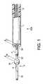
- FIG. 2is a general view of the retractable treatment instrument according to the first embodiment
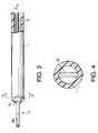
- FIG. 3is a side perspective view of the retractable treatment instrument illustrating a situation where a wide part of a front-end treatment member is retracted into a tip portion of a flexible sheath;
- FIG. 4is a cross-sectional view of the retractable treatment instrument along a line IV-IV of FIG. 3 ;
- FIG. 5is a side perspective view of the retractable treatment instrument illustrating a situation where the front-end treatment member is fully retracted into the tip portion of the flexible sheath;
- FIG. 6is a side perspective view of the retractable treatment instrument illustrating a situation where a half of the front-end treatment member is retracted into the tip portion of the flexible sheath;
- FIG. 7is an enlarged view of a tip portion of a retractable treatment instrument for endoscopes according to a second embodiment of the invention.
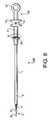
- FIG. 8is a general view of the retractable treatment instrument according to the second embodiment.
- FIG. 9is a side perspective view of the retractable treatment instrument according to the second embodiment, illustrating a situation where a front-end treatment member is fully retracted into the tip portion of a flexible sheath;
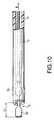
- FIG. 10is a side perspective view of the retractable treatment instrument according to the second embodiment, illustrating a situation where the front-end treatment member is retracted to the midpoint of the tip portion of the flexible sheath;
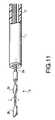
- FIG. 11is a side perspective view of the tip portion of the retractable treatment instrument according to the second embodiment, illustrating a situation where the front-end treatment member is rotated about a center axis of the front-end treatment member;
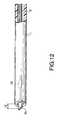
- FIG. 12is a side perspective view of the tip portion of the retractable treatment instrument according to the second embodiment, illustrating a situation where a half of a paddle is retracted into the tip portion of the flexible sheath after the front-end treatment member is rotated;
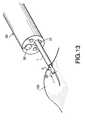
- FIG. 13shows a situation where a mucous membrane is cut by using the retractable treatment instrument according to the second embodiment
- FIG. 14shows a situation where a part of a mucous membrane is ablated by using the retractable treatment instrument according to the second embodiment
- FIGS. 15 and 16show other examples of a cross-sectional shape of the wide part
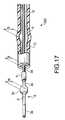
- FIG. 17is an enlarged view of a tip portion of a retractable treatment instrument according to a third embodiment
- FIG. 18is a general view of the retractable treatment instrument according to the third embodiment.
- FIG. 19is a side perspective view of the retractable treatment instrument according to the third embodiment, illustrating a situation where a wide part of a front-end treatment member is retracted into a tip portion of a flexible sheath;
- FIG. 20is a cross-sectional view of the retractable treatment instrument according to the third embodiment along a line XX-XX of FIG. 19 ;
- FIG. 21is a side perspective view of the retractable treatment instrument according to the third embodiment, illustrating a situation where the front-end treatment member is fully retracted into the tip portion of the flexible sheath;
- FIG. 22is a cross-sectional view along a line XXII-XXII of FIG. 21 ;
- FIG. 23is a side perspective view of the retractable treatment instrument according to the third embodiment, illustrating a situation where a half of the front-end treatment member is retracted into the tip portion of the flexible sheath;
- FIG. 24is a side perspective view of a tip portion of a retractable treatment instrument according to a fourth embodiment
- FIG. 25is a cross-sectional view of a retractable treatment instrument according to a fifth embodiment.
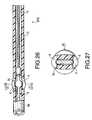
- FIG. 26is a side cross-sectional view of a tip portion of a retractable treatment instrument according to a sixth embodiment
- FIG. 27is a cross sectional view of a flexible sheath according to the sixth embodiment along a line XXVII-XXVII of FIG. 26 ;
- FIG. 28is a perspective view of a tip portion of a retractable treatment instrument according to a seventh embodiment.
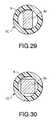
- FIGS. 29 and 30show other examples of a cross-sectional shape of the wide part.
- FIG. 2is a general view of a retractable treatment instrument 20 A for endoscopes according to a first embodiment of the invention.
- the retractable treatment instrument 20 Aincludes a flexible sheath 1 formed of an insulative flexible tube such as a tetrafluoroethylene resin tube.
- a conductive operation wire 2is disposed in the inside of the flexible sheath 1 along the length of the flexible sheath 1 so that the operation wire 2 is movable along an axial direction of the operation wire 2 .
- the flexible sheath 1may be configured such that at least a tip portion thereof is formed of a flexible tube.
- a front-end treatment member 3(for example, formed of a stainless steel plate) is connected to a tip of the operation wire 2 via a connection pipe 4 (for example, formed of a stainless steel pipe) so that the front-end treatment member 3 is retractable with respect to the tip of the flexible sheath 1 . That is, the front-end treatment member 3 moves forward or backward with respect to the tip of the flexible sheath 1 .
- an operation unit 10is connected.
- the operation unit 10is used to move the operation wire 2 along the axial direction of the operation wire 2 in the flexible sheath 1 .
- the operation unit 10includes an operation main body 11 , a fixed hook 12 formed at a base end of the operation main body 11 , and a movable hook 13 slidably attached to the operation main body 11 .
- a base of the operation wire 2which is pulled straight in the flexible sheath 1 toward the operation unit 10 , is connected to the movable hook 13 .
- the operation wire 2moves along the axial direction in the flexible sheath 1 by operating the movable hook 13 to move in a direction P.
- the front-end treatment member 3is protruded from or retracted into the tip portion of the flexible sheath 1 as indicated by a double-headed arrow Q shown in FIG. 2 .
- FIG. 1is an enlarged view of the tip portion of the retractable treatment instrument 20 A.
- the front-end treatment member 3has a rod-like part 3 a having a slender flat shape along an axial direction of the flexible sheath 1 .
- the rod-like part 3 afunctions as a needle-like surgical knife.
- the retractable treatment instrument 20 Amay be formed such that a high-frequency current can be passed through the front-end treatment member 3 via the operation wire 2 .
- a wide part 3 cis formed at the base portion of the front-end treatment member 3 .
- the wide part 3 cmay be formed by elongating a part of the base portion of the front-end treatment member 3 in both directions opposed to each other with respect to a central axis of the front-end treatment member 3 .
- the central axis X of the wide part 3 ccoincides with an extension of a central axis of a tip portion 2 a of the operation wire 2 .
- corners of the wide part 3 care cut away such that an edge of the wide part 3 c bends at 45 degrees at each corner portion.
- each corner partmay be cut away so that the edge has a round shape at each corner portion.
- a slender part 3 dis formed at the base of the wide part 3 c so as to be connected to the connection pipe 4 .
- the wide part 3 cis configured to have a width W larger than an internal diameter d of the flexible sheath 1 to some extent (i.e. W>d). For example, if the internal diameter d is 1.5 mm, a difference (W ⁇ d) may be within 0.1 through 0.4 mm (i.e. 1.07d ⁇ W ⁇ 1.26d).
- the wide part 3 cfits into the inside of the tip portion (i.e. a flexible tube part) of the flexible sheath 1 in such a manner that the edge of the wide part 3 c presses and broadens the inner surface of the flexible sheath 1 as illustrated in FIG. 4 which is a cross-sectional view of the retractable treatment instrument 20 A along a line IV-IV of FIG. 3 .
- the front-end treatment member 3is securely held by the inner surface of the flexible sheath 1 .
- the front-end treatment member 3is fully retracted into the tip portion of the flexible sheath 1 as illustrated in FIG. 5 .
- the front-end treatment member 3can be fixed at desired positions.
- the front-end treatment member 3can be fixed at a position at which the front-end treatment member 3 is protruded by a desirable length L from the tip of the flexible sheath 1 .
- the front-end treatment member 3is fixed in the tip portion of the flexible sheath 1 by a reaction force applied to the edge of the wide part 3 c by the flexible sheath 1 . Therefore, even if an external force smaller than a fixing force of the flexible sheath 1 acts on the front-end treatment member 3 , the front-end treatment member 3 does not move with respect to the tip of the flexible sheath 1 .
- FIG. 7is an enlarged view of a tip portion of a retractable treatment instrument 20 B for endoscopes according to a second embodiment of the invention.
- FIG. 8is a general view of the retractable treatment instrument 20 B according to the second embodiment.
- FIGS. 7 and 8(and in the other drawings of the second embodiment), to elements which are similar to those of the first embodiment, the same reference numbers are assigned, and the detailed description thereof will not be repeated.
- a paddle 3 bis formed at a tip of the rod-like part 3 a of the front-end treatment member 3 .
- the paddle 3 bis configured to have a width W 1 which is substantially equal to the width W of the wide part 3 c or smaller than the width W to some extent.
- a connector 14 to which a high-frequency power source cable can be connectedis located on the movable hook 13 of the operation unit 10 , so that a high-frequency current can be supplied to the front-end treatment member 3 via the operation wire 2 .
- the base part of the flexible sheath 1is attached to the operation main body 11 such that the flexible sheath 1 is fixed in the axial direction thereof and is rotatable about the axis thereof.
- a holding ring 25is fixed.
- the operation unit 10By operating the operation unit 10 to rotate about the axis as illustrated by an arrow R in FIG. 8 while holding the holding ring 25 , the operation wire 2 rotates about the axis in the flexible sheath 1 and the front-end treatment member 3 rotates about the axis. Therefore, the operator can set the direction of the paddle 3 b of the front-end treatment member 3 at a desirable direction by operating the operation unit 10 in a state in which the front-end treatment member 3 fully protrudes from the tip of the flexible sheath 1 .
- the front-end treatment member 3is fully retracted into the tip portion of the flexible sheath 1 as illustrated in FIG. 9 .
- the front-end treatment member 3can be fixed at desired positions.
- the front-end treatment member 3can be fixed at a position at which the front-end treatment member 3 is protruded by a desirable length L 1 from the tip of the flexible sheath 1 .
- the front-end treatment member 3is fixed in the tip portion of the flexible sheath 1 by a reaction force applied to the edge of the wide part 3 c by the flexible sheath 1 . Therefore, even if an external force smaller than a fixing force of the flexible sheath 1 acts on the paddle 3 b , the front-end treatment member 3 does not move in the axial direction and does not rotate about the axis with respect to the tip of the flexible sheath 1 .
- the direction (i.e. a rotational position about the axis of the front-end treatment member 3 ) of the paddle 3can be set at a desirable direction by operating the operation unit 10 as indicated by an arrow r in FIG. 11 .
- the paddle 3By retracting the front-end treatment member 3 into the tip portion of the flexible sheath 1 by operating the operation unit 10 after the direction of the paddle 3 b is adjusted at a desired direction, the paddle 3 is fixed at the desired direction while the protruding length from the tip of the flexible sheath 1 is set at a desired length L 2 (see FIG. 12 ). Therefore, a high-frequency incision treatment can be performed in a safe condition using the retractable treatment instrument 20 B.
- FIG. 13shows a situation where a mucous membrane 100 is cut by using the retractable treatment instrument 20 B which is inserted into an instrument-inserting channel 51 of an endoscope 50 . Such an endoscopic operation is performed by observing the mucous membrane 100 through an observation window 52 .
- an operatoroperates the retractable treatment instrument 20 B so that the paddle 3 b is perpendicularly pressed against the mucous membrane 100 .
- FIG. 14shows a situation where a part of the mucous membrane 100 is ablated by using the retractable treatment instrument 20 B which is inserted into the instrument-inserting channel 51 of the endoscope 50 .
- the paddle 3 bis positioned horizontally with respect to an inner surface of the mucous membrane 100 and is inserted under the inner surface of the mucous membrane 100 to perform an ablation treatment of mucous membrane 100 .
- FIGS. 15 and 16show other examples of a cross-sectional shape of the wide part 3 c .
- the wide part 3 chas an elliptical cross-sectional form (along a line IV-IV of FIG. 3 ).
- the wide part 3 chas a rectangular cross-sectional form (along a line IV-IV of FIG. 3 ).
- FIG. 17is an enlarged view of a tip portion of a retractable treatment instrument 20 C for endoscopes according to a third embodiment of the invention.
- FIG. 18is a general view of the retractable treatment instrument 20 C according to the third embodiment.
- FIGS. 17 and 18(and in the other drawings of the third embodiment), to elements which are similar to those of the first and second embodiments, the same reference numbers are assigned, and the detailed description thereof will not be repeated.
- the retractable treatment instrument 20 Cis provided with the connector 14 to which a high-frequency power source cable is connected. Therefore, the retractable treatment instrument 20 C is used as a high-frequency incision instrument. If the retractable treatment instrument 20 C is used as a mechanical incision instrument, it is not necessary to connect the high-frequency power source cable to the connector 14 .
- the wide part 3 cfits into the inside of the tip portion (i.e. a flexible tube part) of the flexible sheath 1 in such a manner that the edge of the wide part 3 c presses and broaden the inner surface of the flexible sheath 1 C as illustrated in FIG. 20 which is a cross-sectional view the retractable treatment instrument 20 A along a line XX-XX of FIG. 19 .
- the front-end treatment member 3is securely held by the inner surface of the flexible sheath 1 C.
- an expanded part 5is formed in the vicinity of the tip of the flexible sheath 1 C.
- the expanded part 5has an adequate size to hold the wide part 3 c of the front-end treatment member 3 .
- the expanded part 5is formed by expanding a part of the flexible sheath 1 C uniformly in a radial direction.
- the inner diameter D of the expanded part 5is equal to or slightly larger than the width W of the wide part 3 c (i.e. D ⁇ W).
- the front-end treatment member 3is fully retracted into the tip portion of the flexible sheath 1 C.
- the wide part 3 cmoves backward while the wide part 3 c presses the inner surface of the tip portion of the flexible sheath 1 C and produces the friction between the edge of the wide part 3 c and the inner surface of the flexible sheath 1 C. If the wide part 3 c reaches the position of the expanded part 5 , the friction between the edge of the wide part 3 c and the inner surface of the sheath 1 C becomes substantially zero. In this state, the wide part 3 c fits into the expanded part 5 as illustrated in FIG. 22 which is a cross-sectional view the retractable treatment instrument 20 C along a line XXII-XXII of FIG. 21 .
- the wide part 3 cdoes not get out of the expanded part 5 unless the operation wire 2 is pulled or pressed by a force larger than a certain strength (which is adequate to press and expand the inner surface of the flexible sheath 1 C). Therefore, by locating the wide part 3 c of the front-end treatment member 3 at the position of the expanded part 5 before attachment work where the retractable treatment instrument 20 C is inserted into an instrument-inserting channel of an endoscope, it becomes possible to prevent the front-end treatment member 3 from getting out of the tip of the flexible sheath 1 C and thereby damaging an inner wall of the instrument-inserting channel of the endoscope during the attachment work.
- the front-end treatment member 3is securely held at the position shown in FIG. 23 . That is, an endoscopic treatment can be performed in a safe condition while the protruding length of the rod-like part 3 a from the tip of the flexible sheath 1 C is set at a desired length.
- FIG. 24is an enlarged view of a tip portion of a retractable treatment instrument 20 D for endoscopes according to a fourth embodiment of the invention.
- FIG. 24(and in the other drawings of the fourth embodiment), to elements which are similar to those of the first through third embodiments, the same reference numbers are assigned, and the detailed description thereof will not be repeated.
- a flexible sheath 1 Dhas rear and front expanded parts 5 A and 5 B at positions along the lengthwise direction of the flexible sheath 1 D.
- the front-end treatment member 3is fully retracted into the tip portion of the flexible sheath 1 D.
- the front-end treatment member 3is held at a position at which the protruding length of the rod-like part 3 a from the tip of the flexible sheath 1 D is set at a length L 4 .
- the flexible sheath 1 Dis configured to have two expanded parts in this embodiment, the flexible sheath may be condfigured to have three or more expanded parts to securely fix the front-end treatment member 3 at desirable positions.
- the state where the protruding length of the rod-like part 3 a from the tip of the flexible sheath 1 C is L 4is securely maintained.
- the protruding length of L 4does not change unless an external force larger than a certain strength (which is adequate to press and expand the inner surface of the flexible sheath 1 D) acts on the front-end treatment member 3 . Accordingly, an endoscopic treatment can be performed in a safe condition while the protruding length of the rod-like part 3 a from the tip of the flexible sheath 1 C is set at a desired length.
- FIG. 25shows a cross-sectional shape of a flexible sheath 1 G of a retractable treatment instrument 20 G according to a fifth embodiment of the invention.
- the cross-sectional shape of FIG. 25corresponds to the cross-sectional shape along a line XXII-XXII of FIG. 21 .
- the expanded part 5 shown in FIG. 25is formed by pressing a part of the flexible sheath 1 G from both sides of the flexible sheath 1 G (for example, while heating the part of the flexible sheath 1 G) so that the part of the flexible sheath 1 G is expanded in a direction perpendicular to a pressing direction in which the flexible sheath 1 G is pressed.
- FIG. 26is a side cross-sectional view of a tip portion of a retractable treatment instrument 20 E for endoscopes according to a sixth embodiment of the invention.
- FIG. 27is a cross sectional view of a flexible sheath 1 E according to the sixth embodiment along a line XXVII-XXVII of FIG. 26 .
- the same reference numbersare assigned, and the detailed description thereof will not be repeated.
- the flexible sheath 1 Ehas cut off parts 6 which is formed, for example, by cutting off a part of the expanded part 5 (which may be formed by a process described in the fifth embodiment) projected outward from the outside diameter of the flexible sheath 1 E.
- FIG. 28is a perspective view of a tip portion of a retractable treatment instrument 20 F for endoscopes according to a seventh embodiment of the invention.
- FIG. 28to elements which are similar to those of the first through sixth embodiments, the same reference numbers are assigned, and the detailed description thereof will not be repeated.
- the retractable treatment instrument 20 Fincludes the flexible sheath 1 D having two expanded parts 5 A and 5 B. As shown in FIG. 28 , the paddle 3 b is formed at the tip pf the rod-like part 3 a of the front-end treatment member 3 .
- FIGS. 29 and 30show other examples of a cross-sectional shape of the wide part 3 c .
- the examples of the wide part 3 c shown in FIGS. 29 and 30have an elliptical cross-sectional form and a rectangular cross-sectional form, respectively.
- the wide part 3 c of each of the examplesclosely fits into an expanded part (e.g. the expanded part 5 ) of a flexible sheath (e.g. the flexible sheath 1 C).
- an endoscopic treatment using the paddle 3 bcan be performed in a safe condition while the protruding length of the rod-like part 3 a from the tip of the flexible sheath 1 D is set at a desired length.
- the retractable treatment instrument 20 A of the first embodimentmay be configured such that the operation wire 2 is roratable about the axis relative to the flexible sheath 1 .
Landscapes
- Health & Medical Sciences (AREA)
- Life Sciences & Earth Sciences (AREA)
- Surgery (AREA)
- Engineering & Computer Science (AREA)
- Animal Behavior & Ethology (AREA)
- Veterinary Medicine (AREA)
- Biomedical Technology (AREA)
- Heart & Thoracic Surgery (AREA)
- Medical Informatics (AREA)
- Molecular Biology (AREA)
- Nuclear Medicine, Radiotherapy & Molecular Imaging (AREA)
- General Health & Medical Sciences (AREA)
- Public Health (AREA)
- Orthopedic Medicine & Surgery (AREA)
- Vascular Medicine (AREA)
- Cardiology (AREA)
- Physics & Mathematics (AREA)
- Plasma & Fusion (AREA)
- Otolaryngology (AREA)
- Surgical Instruments (AREA)
- Endoscopes (AREA)
Abstract
Description
1.07d≦W≦1.26d
Claims (12)
1.07d≦W≦1.26d
Applications Claiming Priority (4)
| Application Number | Priority Date | Filing Date | Title |
|---|---|---|---|
| JP2004-085846 | 2004-03-24 | ||
| JP2004085846AJP4495492B2 (en) | 2004-03-24 | 2004-03-24 | Endoscopic treatment tool for endoscope |
| JP2004-101659 | 2004-03-31 | ||
| JP2004101659AJP4495501B2 (en) | 2004-03-31 | 2004-03-31 | Endoscopic treatment tool for endoscope |
Publications (2)
| Publication Number | Publication Date |
|---|---|
| US20050215853A1 US20050215853A1 (en) | 2005-09-29 |
| US7749156B2true US7749156B2 (en) | 2010-07-06 |
Family
ID=34576009
Family Applications (1)
| Application Number | Title | Priority Date | Filing Date |
|---|---|---|---|
| US11/086,305Expired - Fee RelatedUS7749156B2 (en) | 2004-03-24 | 2005-03-23 | Retractable treatment instrument for endoscope |
Country Status (4)
| Country | Link |
|---|---|
| US (1) | US7749156B2 (en) |
| DE (1) | DE102005013872B4 (en) |
| FR (1) | FR2867961B1 (en) |
| GB (1) | GB2412323B (en) |
Cited By (55)
| Publication number | Priority date | Publication date | Assignee | Title |
|---|---|---|---|---|
| US20060068428A1 (en)* | 2003-11-03 | 2006-03-30 | Duke University | Identification of genetic markers associated with parkinson disease |
| US20070225554A1 (en)* | 2006-03-22 | 2007-09-27 | Boston Scientific Scimed, Inc. | Endoscope working channel with multiple functionality |
| US20080114203A1 (en)* | 2006-11-09 | 2008-05-15 | Crank Justin M | Orientation Adapter for Injection Tube in Flexible Endoscope |
| US20100022837A1 (en)* | 2007-04-20 | 2010-01-28 | Tsutomu Ishiguro | Surgical instrument and endoscope surgical system having surgical instrument |
| US20110015614A1 (en)* | 2008-12-16 | 2011-01-20 | Rykhus Jr Robert L | Needleless injection device components, systems, and methods |
| US20110046600A1 (en)* | 2008-12-05 | 2011-02-24 | Crank Justin M | Devices, systems, and related methods for delivery of fluid to tissue |
| US20110172631A1 (en)* | 2008-12-05 | 2011-07-14 | Crank Justin M | Needleless injection device components, systems, and methods |
| US20110238006A1 (en)* | 2008-12-16 | 2011-09-29 | Crank Justin M | Needleless injection device components, systems, and methods |
| US8182422B2 (en) | 2005-12-13 | 2012-05-22 | Avantis Medical Systems, Inc. | Endoscope having detachable imaging device and method of using |
| US8197399B2 (en) | 2006-05-19 | 2012-06-12 | Avantis Medical Systems, Inc. | System and method for producing and improving images |
| US8235887B2 (en) | 2006-01-23 | 2012-08-07 | Avantis Medical Systems, Inc. | Endoscope assembly with retroscope |
| US8287446B2 (en) | 2006-04-18 | 2012-10-16 | Avantis Medical Systems, Inc. | Vibratory device, endoscope having such a device, method for configuring an endoscope, and method of reducing looping of an endoscope |
| US8289381B2 (en) | 2005-01-05 | 2012-10-16 | Avantis Medical Systems, Inc. | Endoscope with an imaging catheter assembly and method of configuring an endoscope |
| US8628494B2 (en) | 2009-07-20 | 2014-01-14 | Ams Research Corporation | Devices, systems, and methods for delivering fluid to tissue |
| US8797392B2 (en) | 2005-01-05 | 2014-08-05 | Avantis Medical Sytems, Inc. | Endoscope assembly with a polarizing filter |
| US8872906B2 (en) | 2005-01-05 | 2014-10-28 | Avantis Medical Systems, Inc. | Endoscope assembly with a polarizing filter |
| US8876759B2 (en) | 2008-12-05 | 2014-11-04 | Ams Research Corporation | Devices, systems and methods for delivering fluid to tissue |
| US8926502B2 (en) | 2011-03-07 | 2015-01-06 | Endochoice, Inc. | Multi camera endoscope having a side service channel |
| US8945045B2 (en) | 2009-07-20 | 2015-02-03 | Ams Research Corporation | Needleless injection device components, systems, and methods |
| US8979797B2 (en) | 2010-12-16 | 2015-03-17 | Ams Research Corporation | High pressure delivery system and method for treating pelvic disorder using large molecule therapeutics |
| US9044185B2 (en) | 2007-04-10 | 2015-06-02 | Avantis Medical Systems, Inc. | Method and device for examining or imaging an interior surface of a cavity |
| US9101268B2 (en) | 2009-06-18 | 2015-08-11 | Endochoice Innovation Center Ltd. | Multi-camera endoscope |
| US9101287B2 (en) | 2011-03-07 | 2015-08-11 | Endochoice Innovation Center Ltd. | Multi camera endoscope assembly having multiple working channels |
| US9101266B2 (en) | 2011-02-07 | 2015-08-11 | Endochoice Innovation Center Ltd. | Multi-element cover for a multi-camera endoscope |
| US9138535B2 (en) | 2009-07-20 | 2015-09-22 | Ams Research Corporation | High pressure injection catheter systems |
| US9283353B2 (en) | 2008-12-05 | 2016-03-15 | Justin M. Crank | Devices, systems and related methods for delivery of fluid to tissue |
| US9314147B2 (en) | 2011-12-13 | 2016-04-19 | Endochoice Innovation Center Ltd. | Rotatable connector for an endoscope |
| US9320419B2 (en) | 2010-12-09 | 2016-04-26 | Endochoice Innovation Center Ltd. | Fluid channeling component of a multi-camera endoscope |
| US9370646B2 (en) | 2008-12-05 | 2016-06-21 | Justin M. Crank | Devices, systems and methods for delivering fluid to tissue |
| US9402533B2 (en) | 2011-03-07 | 2016-08-02 | Endochoice Innovation Center Ltd. | Endoscope circuit board assembly |
| US9421326B2 (en) | 2008-12-29 | 2016-08-23 | Robert L. Rykhus | Method and apparatus for compensating for injection media viscosity in a pressurized drug injection system |
| US9492063B2 (en) | 2009-06-18 | 2016-11-15 | Endochoice Innovation Center Ltd. | Multi-viewing element endoscope |
| US9554692B2 (en) | 2009-06-18 | 2017-01-31 | EndoChoice Innovation Ctr. Ltd. | Multi-camera endoscope |
| US9560954B2 (en) | 2012-07-24 | 2017-02-07 | Endochoice, Inc. | Connector for use with endoscope |
| US9560953B2 (en) | 2010-09-20 | 2017-02-07 | Endochoice, Inc. | Operational interface in a multi-viewing element endoscope |
| US9642513B2 (en) | 2009-06-18 | 2017-05-09 | Endochoice Inc. | Compact multi-viewing element endoscope system |
| US9655502B2 (en) | 2011-12-13 | 2017-05-23 | EndoChoice Innovation Center, Ltd. | Removable tip endoscope |
| US9706903B2 (en) | 2009-06-18 | 2017-07-18 | Endochoice, Inc. | Multiple viewing elements endoscope system with modular imaging units |
| US9713417B2 (en) | 2009-06-18 | 2017-07-25 | Endochoice, Inc. | Image capture assembly for use in a multi-viewing elements endoscope |
| US9814374B2 (en) | 2010-12-09 | 2017-11-14 | Endochoice Innovation Center Ltd. | Flexible electronic circuit board for a multi-camera endoscope |
| US9872609B2 (en) | 2009-06-18 | 2018-01-23 | Endochoice Innovation Center Ltd. | Multi-camera endoscope |
| US9901244B2 (en) | 2009-06-18 | 2018-02-27 | Endochoice, Inc. | Circuit board assembly of a multiple viewing elements endoscope |
| US9986899B2 (en) | 2013-03-28 | 2018-06-05 | Endochoice, Inc. | Manifold for a multiple viewing elements endoscope |
| US9993142B2 (en) | 2013-03-28 | 2018-06-12 | Endochoice, Inc. | Fluid distribution device for a multiple viewing elements endoscope |
| US10080486B2 (en) | 2010-09-20 | 2018-09-25 | Endochoice Innovation Center Ltd. | Multi-camera endoscope having fluid channels |
| US10165929B2 (en) | 2009-06-18 | 2019-01-01 | Endochoice, Inc. | Compact multi-viewing element endoscope system |
| US10203493B2 (en) | 2010-10-28 | 2019-02-12 | Endochoice Innovation Center Ltd. | Optical systems for multi-sensor endoscopes |
| US10499794B2 (en) | 2013-05-09 | 2019-12-10 | Endochoice, Inc. | Operational interface in a multi-viewing element endoscope |
| US11278190B2 (en) | 2009-06-18 | 2022-03-22 | Endochoice, Inc. | Multi-viewing element endoscope |
| US11547275B2 (en) | 2009-06-18 | 2023-01-10 | Endochoice, Inc. | Compact multi-viewing element endoscope system |
| US11864734B2 (en) | 2009-06-18 | 2024-01-09 | Endochoice, Inc. | Multi-camera endoscope |
| US11889986B2 (en) | 2010-12-09 | 2024-02-06 | Endochoice, Inc. | Flexible electronic circuit board for a multi-camera endoscope |
| US12137873B2 (en) | 2009-06-18 | 2024-11-12 | Endochoice, Inc. | Compact multi-viewing element endoscope system |
| US12204087B2 (en) | 2010-10-28 | 2025-01-21 | Endochoice, Inc. | Optical systems for multi-sensor endoscopes |
| US12220105B2 (en) | 2010-06-16 | 2025-02-11 | Endochoice, Inc. | Circuit board assembly of a multiple viewing elements endoscope |
Families Citing this family (11)
| Publication number | Priority date | Publication date | Assignee | Title |
|---|---|---|---|---|
| JP4731274B2 (en)* | 2005-10-19 | 2011-07-20 | Hoya株式会社 | Endoscopic high-frequency incision tool |
| JP4774272B2 (en)* | 2005-10-19 | 2011-09-14 | Hoya株式会社 | Endoscopic high-frequency incision tool |
| JP4425227B2 (en)* | 2006-02-28 | 2010-03-03 | Hoya株式会社 | Endoscopic high-frequency treatment instrument |
| US8414574B2 (en)* | 2006-06-01 | 2013-04-09 | Hoya Corporation | Treatment instrument having a front-end treatment member |
| JP4598197B2 (en)* | 2006-11-09 | 2010-12-15 | Hoya株式会社 | Endoscopic treatment tool |
| JP5415727B2 (en)* | 2008-08-13 | 2014-02-12 | オリンパスメディカルシステムズ株式会社 | Endoscopic treatment tool |
| JP5393491B2 (en)* | 2009-03-04 | 2014-01-22 | Hoya株式会社 | Ultrasound endoscope puncture needle device |
| EP2826426B1 (en)* | 2012-03-15 | 2018-04-25 | Terumo Kabushiki Kaisha | Applicator |
| US9717556B2 (en)* | 2012-12-21 | 2017-08-01 | Cook Medical Technologies Llc | Collet for an endoscopic needle knife |
| KR101374320B1 (en)* | 2013-10-15 | 2014-03-17 | 홍문기 | Steerable electrode catheter assembly |
| CN105012014B (en)* | 2015-08-20 | 2017-08-08 | 鑫海合星科技(大连)有限公司 | Flexible smoking knife |
Citations (30)
| Publication number | Priority date | Publication date | Assignee | Title |
|---|---|---|---|---|
| US4492832A (en) | 1982-12-23 | 1985-01-08 | Neomed, Incorporated | Hand-controllable switching device for electrosurgical instruments |
| DE3707820A1 (en) | 1986-03-12 | 1987-09-17 | Olympus Optical Co | High-frequency instrument for medical treatment |
| US4733662A (en) | 1987-01-20 | 1988-03-29 | Minnesota Mining And Manufacturing Company | Tissue gripping and cutting assembly for surgical instrument |
| JPH01201248A (en) | 1988-02-05 | 1989-08-14 | Olympus Optical Co Ltd | Treatment utensil for endoscope |
| US5053041A (en)* | 1990-03-12 | 1991-10-01 | Ansari Shapoor S | Vessel holder |
| JPH078503A (en) | 1993-06-22 | 1995-01-13 | Olympus Optical Co Ltd | High frequency medical treatment tool |
| US5401274A (en) | 1992-04-20 | 1995-03-28 | Olympus Optical Co., Ltd. | High-frequency treating instrument |
| US5423814A (en)* | 1992-05-08 | 1995-06-13 | Loma Linda University Medical Center | Endoscopic bipolar coagulation device |
| US5460629A (en) | 1991-02-06 | 1995-10-24 | Advanced Surgical, Inc. | Electrosurgical device and method |
| US5542945A (en) | 1993-10-05 | 1996-08-06 | Delma Elektro-U. Medizinische Apparatebau Gesellschaft Mbh | Electro-surgical radio-frequency instrument |
| JPH08299355A (en) | 1995-05-02 | 1996-11-19 | Olympus Optical Co Ltd | High frequency knife |
| US5899850A (en) | 1997-04-03 | 1999-05-04 | Asahi Kogaku Kogyo Kabushiki Kaisha | Treatment accessories for an endoscope |
| EP0919196A2 (en) | 1997-11-25 | 1999-06-02 | S.L.T. Japan Co., Ltd. | Apparatus for medical treatment |
| US6007514A (en) | 1997-09-30 | 1999-12-28 | Nita; Henry | Ultrasound system with pathfinding guidewire |
| US6193717B1 (en) | 1997-10-16 | 2001-02-27 | Asahi Kogaku Kogyo Kabushiki Kaisha | Treating instrument for endoscope |
| WO2001058360A2 (en) | 2000-02-08 | 2001-08-16 | Medsource Technologies, Llc | Endoscopic tool restraint |
| US6299625B1 (en)* | 1998-08-12 | 2001-10-09 | Karl Storz Gmbh & Co. Kg | Handle for a medical instrument |
| JP2002113015A (en) | 2000-10-05 | 2002-04-16 | Olympus Optical Co Ltd | High frequency endo-therapy accessory |
| JP2002153484A (en) | 2000-11-20 | 2002-05-28 | Asahi Optical Co Ltd | High-frequency incision instrument for endoscope |
| US6409727B1 (en)* | 1999-10-15 | 2002-06-25 | Scimed Life Systems, Inc. | Multifilar flexible rotary shaft and medical instruments incorporating the same |
| US6428503B1 (en) | 1999-01-19 | 2002-08-06 | Atc Technologies, Inc. | Surgical instrument for providing suction and irrigation |
| EP1234543A1 (en) | 2000-08-04 | 2002-08-28 | Olympus Optical Co., Ltd. | Sampler, sampling method, and substance transplanting method |
| US20020120253A1 (en) | 2001-02-26 | 2002-08-29 | Asahi Kogaku Kogyo Kabushiki Kaisha | Treatment tools for endoscope |
| JP2002253559A (en) | 2001-03-01 | 2002-09-10 | Asahi Optical Co Ltd | Wire loop type treatment instrument for endoscope |
| US20030040744A1 (en) | 2001-08-27 | 2003-02-27 | Gyrus Medical, Inc. | Bipolar electrosurgical hook probe for cutting and coagulating tissue |
| US20030144663A1 (en)* | 2000-07-22 | 2003-07-31 | Sascha Berberich | Medical instrument, in particular a resectoscope |
| US6605104B2 (en)* | 1994-08-02 | 2003-08-12 | Olympus Optical Co., Ltd. | Grasping forceps for endoscope |
| JP2003299663A (en) | 2002-03-18 | 2003-10-21 | Olympus Optical Co Ltd | Endoscope inserting system |
| US20040039249A1 (en) | 2002-04-12 | 2004-02-26 | Olympus Optical Co., Ltd. | Incising device for use with an endoscope |
| US20050177151A1 (en)* | 2001-06-20 | 2005-08-11 | Coen Thomas P. | Irrigation sheath |
Family Cites Families (2)
| Publication number | Priority date | Publication date | Assignee | Title |
|---|---|---|---|---|
| US5224954A (en)* | 1991-02-19 | 1993-07-06 | Dexide, Inc. | Combination surgical trocar cannula and rake assembly |
| JPH1176403A (en)* | 1997-07-11 | 1999-03-23 | Olympus Optical Co Ltd | Surgical treatment instrument |
- 2005
- 2005-03-23USUS11/086,305patent/US7749156B2/ennot_activeExpired - Fee Related
- 2005-03-23FRFR0502870Apatent/FR2867961B1/ennot_activeExpired - Fee Related
- 2005-03-24GBGB0506171Apatent/GB2412323B/ennot_activeExpired - Fee Related
- 2005-03-24DEDE102005013872.1Apatent/DE102005013872B4/ennot_activeExpired - Lifetime
Patent Citations (33)
| Publication number | Priority date | Publication date | Assignee | Title |
|---|---|---|---|---|
| US4492832A (en) | 1982-12-23 | 1985-01-08 | Neomed, Incorporated | Hand-controllable switching device for electrosurgical instruments |
| DE3707820A1 (en) | 1986-03-12 | 1987-09-17 | Olympus Optical Co | High-frequency instrument for medical treatment |
| US4733662A (en) | 1987-01-20 | 1988-03-29 | Minnesota Mining And Manufacturing Company | Tissue gripping and cutting assembly for surgical instrument |
| JPH01201248A (en) | 1988-02-05 | 1989-08-14 | Olympus Optical Co Ltd | Treatment utensil for endoscope |
| US5053041A (en)* | 1990-03-12 | 1991-10-01 | Ansari Shapoor S | Vessel holder |
| US5460629A (en) | 1991-02-06 | 1995-10-24 | Advanced Surgical, Inc. | Electrosurgical device and method |
| US5401274A (en) | 1992-04-20 | 1995-03-28 | Olympus Optical Co., Ltd. | High-frequency treating instrument |
| US5423814A (en)* | 1992-05-08 | 1995-06-13 | Loma Linda University Medical Center | Endoscopic bipolar coagulation device |
| JPH078503A (en) | 1993-06-22 | 1995-01-13 | Olympus Optical Co Ltd | High frequency medical treatment tool |
| US5542945A (en) | 1993-10-05 | 1996-08-06 | Delma Elektro-U. Medizinische Apparatebau Gesellschaft Mbh | Electro-surgical radio-frequency instrument |
| US6605104B2 (en)* | 1994-08-02 | 2003-08-12 | Olympus Optical Co., Ltd. | Grasping forceps for endoscope |
| JPH08299355A (en) | 1995-05-02 | 1996-11-19 | Olympus Optical Co Ltd | High frequency knife |
| US5899850A (en) | 1997-04-03 | 1999-05-04 | Asahi Kogaku Kogyo Kabushiki Kaisha | Treatment accessories for an endoscope |
| US6007514A (en) | 1997-09-30 | 1999-12-28 | Nita; Henry | Ultrasound system with pathfinding guidewire |
| US6193717B1 (en) | 1997-10-16 | 2001-02-27 | Asahi Kogaku Kogyo Kabushiki Kaisha | Treating instrument for endoscope |
| EP0919196A2 (en) | 1997-11-25 | 1999-06-02 | S.L.T. Japan Co., Ltd. | Apparatus for medical treatment |
| US6299625B1 (en)* | 1998-08-12 | 2001-10-09 | Karl Storz Gmbh & Co. Kg | Handle for a medical instrument |
| US6428503B1 (en) | 1999-01-19 | 2002-08-06 | Atc Technologies, Inc. | Surgical instrument for providing suction and irrigation |
| US6409727B1 (en)* | 1999-10-15 | 2002-06-25 | Scimed Life Systems, Inc. | Multifilar flexible rotary shaft and medical instruments incorporating the same |
| WO2001058360A2 (en) | 2000-02-08 | 2001-08-16 | Medsource Technologies, Llc | Endoscopic tool restraint |
| US20030144663A1 (en)* | 2000-07-22 | 2003-07-31 | Sascha Berberich | Medical instrument, in particular a resectoscope |
| EP1234543A1 (en) | 2000-08-04 | 2002-08-28 | Olympus Optical Co., Ltd. | Sampler, sampling method, and substance transplanting method |
| JP2002113015A (en) | 2000-10-05 | 2002-04-16 | Olympus Optical Co Ltd | High frequency endo-therapy accessory |
| US6767348B2 (en) | 2000-10-05 | 2004-07-27 | Olympus Corporation | High-frequency treatment device |
| JP2002153484A (en) | 2000-11-20 | 2002-05-28 | Asahi Optical Co Ltd | High-frequency incision instrument for endoscope |
| US20020120253A1 (en) | 2001-02-26 | 2002-08-29 | Asahi Kogaku Kogyo Kabushiki Kaisha | Treatment tools for endoscope |
| JP2002253559A (en) | 2001-03-01 | 2002-09-10 | Asahi Optical Co Ltd | Wire loop type treatment instrument for endoscope |
| US20050177151A1 (en)* | 2001-06-20 | 2005-08-11 | Coen Thomas P. | Irrigation sheath |
| US20030040744A1 (en) | 2001-08-27 | 2003-02-27 | Gyrus Medical, Inc. | Bipolar electrosurgical hook probe for cutting and coagulating tissue |
| JP2003299663A (en) | 2002-03-18 | 2003-10-21 | Olympus Optical Co Ltd | Endoscope inserting system |
| US20030225312A1 (en) | 2002-03-18 | 2003-12-04 | Anthony Kalloo | Endoscopic system for treating inside of body cavity |
| US20040039249A1 (en) | 2002-04-12 | 2004-02-26 | Olympus Optical Co., Ltd. | Incising device for use with an endoscope |
| US6949099B2 (en)* | 2002-04-12 | 2005-09-27 | Olympus Corporation | Incising device for use with an endoscope |
Non-Patent Citations (6)
| Title |
|---|
| English Language Abstract of JP 1-201248. |
| English Language Abstract of JP 2002-153484. |
| English Language Abstract of JP 2002-253559. |
| English Language Abstract of JP 7-008503. |
| English Language Abstract of JP 8-299355. |
| U.S. Appl. No. 11/086,436, filed Mar. 23, 2005. |
Cited By (108)
| Publication number | Priority date | Publication date | Assignee | Title |
|---|---|---|---|---|
| US20060068428A1 (en)* | 2003-11-03 | 2006-03-30 | Duke University | Identification of genetic markers associated with parkinson disease |
| US8872906B2 (en) | 2005-01-05 | 2014-10-28 | Avantis Medical Systems, Inc. | Endoscope assembly with a polarizing filter |
| US8797392B2 (en) | 2005-01-05 | 2014-08-05 | Avantis Medical Sytems, Inc. | Endoscope assembly with a polarizing filter |
| US8289381B2 (en) | 2005-01-05 | 2012-10-16 | Avantis Medical Systems, Inc. | Endoscope with an imaging catheter assembly and method of configuring an endoscope |
| US8182422B2 (en) | 2005-12-13 | 2012-05-22 | Avantis Medical Systems, Inc. | Endoscope having detachable imaging device and method of using |
| US11529044B2 (en) | 2005-12-13 | 2022-12-20 | Psip Llc | Endoscope imaging device |
| US10045685B2 (en) | 2006-01-23 | 2018-08-14 | Avantis Medical Systems, Inc. | Endoscope |
| US8235887B2 (en) | 2006-01-23 | 2012-08-07 | Avantis Medical Systems, Inc. | Endoscope assembly with retroscope |
| US20110213202A1 (en)* | 2006-03-22 | 2011-09-01 | Boston Scientific Scimed, Inc. | Endoscope working channel with multiple functionality |
| US7918783B2 (en)* | 2006-03-22 | 2011-04-05 | Boston Scientific Scimed, Inc. | Endoscope working channel with multiple functionality |
| US8834352B2 (en)* | 2006-03-22 | 2014-09-16 | Boston Scientific Scimed, Inc. | Endoscope working channel with multiple functionality |
| US20070225554A1 (en)* | 2006-03-22 | 2007-09-27 | Boston Scientific Scimed, Inc. | Endoscope working channel with multiple functionality |
| US8287446B2 (en) | 2006-04-18 | 2012-10-16 | Avantis Medical Systems, Inc. | Vibratory device, endoscope having such a device, method for configuring an endoscope, and method of reducing looping of an endoscope |
| US8197399B2 (en) | 2006-05-19 | 2012-06-12 | Avantis Medical Systems, Inc. | System and method for producing and improving images |
| US8310530B2 (en) | 2006-05-19 | 2012-11-13 | Avantis Medical Systems, Inc. | Device and method for reducing effects of video artifacts |
| US8587645B2 (en) | 2006-05-19 | 2013-11-19 | Avantis Medical Systems, Inc. | Device and method for reducing effects of video artifacts |
| US8852084B2 (en) | 2006-11-09 | 2014-10-07 | Ams Research Corporation | Orientation adapter for injection tube in flexible endoscope |
| US7993264B2 (en)* | 2006-11-09 | 2011-08-09 | Ams Research Corporation | Orientation adapter for injection tube in flexible endoscope |
| US20080114203A1 (en)* | 2006-11-09 | 2008-05-15 | Crank Justin M | Orientation Adapter for Injection Tube in Flexible Endoscope |
| US9044185B2 (en) | 2007-04-10 | 2015-06-02 | Avantis Medical Systems, Inc. | Method and device for examining or imaging an interior surface of a cavity |
| US10354382B2 (en) | 2007-04-10 | 2019-07-16 | Avantis Medical Systems, Inc. | Method and device for examining or imaging an interior surface of a cavity |
| US9613418B2 (en) | 2007-04-10 | 2017-04-04 | Avantis Medical Systems, Inc. | Method and device for examining or imaging an interior surface of a cavity |
| US8282543B2 (en)* | 2007-04-20 | 2012-10-09 | Olympus Medical Systems Corp. | Surgical instrument and endoscope surgical system having surgical instrument |
| US20100022837A1 (en)* | 2007-04-20 | 2010-01-28 | Tsutomu Ishiguro | Surgical instrument and endoscope surgical system having surgical instrument |
| US9017282B2 (en) | 2008-12-05 | 2015-04-28 | Ams Research Corporation | Needleless injection device components, systems, and methods |
| US20110172631A1 (en)* | 2008-12-05 | 2011-07-14 | Crank Justin M | Needleless injection device components, systems, and methods |
| US8876759B2 (en) | 2008-12-05 | 2014-11-04 | Ams Research Corporation | Devices, systems and methods for delivering fluid to tissue |
| US9283353B2 (en) | 2008-12-05 | 2016-03-15 | Justin M. Crank | Devices, systems and related methods for delivery of fluid to tissue |
| US20110046600A1 (en)* | 2008-12-05 | 2011-02-24 | Crank Justin M | Devices, systems, and related methods for delivery of fluid to tissue |
| US8366657B2 (en) | 2008-12-05 | 2013-02-05 | Ams Research Corporation | Needleless injection device components, systems, and methods |
| US9370646B2 (en) | 2008-12-05 | 2016-06-21 | Justin M. Crank | Devices, systems and methods for delivering fluid to tissue |
| US8852142B2 (en) | 2008-12-16 | 2014-10-07 | Ams Research Corporation | Needleless injection device components, systems, and methods |
| US20110238006A1 (en)* | 2008-12-16 | 2011-09-29 | Crank Justin M | Needleless injection device components, systems, and methods |
| US9579462B2 (en) | 2008-12-16 | 2017-02-28 | Astora Women's Health Holdings, Llc | Needleless injection device components, systems, and methods |
| US20110015614A1 (en)* | 2008-12-16 | 2011-01-20 | Rykhus Jr Robert L | Needleless injection device components, systems, and methods |
| US9295823B2 (en) | 2008-12-16 | 2016-03-29 | Robert L. Rykhus, Jr. | Needleless injection device components, systems, and methods |
| US9795733B2 (en) | 2008-12-29 | 2017-10-24 | Astora Women's Health Holdings, Llc | Method and apparatus for compensating for injection media viscosity in a pressurized drug injection system |
| US9421326B2 (en) | 2008-12-29 | 2016-08-23 | Robert L. Rykhus | Method and apparatus for compensating for injection media viscosity in a pressurized drug injection system |
| US10791910B2 (en) | 2009-06-18 | 2020-10-06 | Endochoice, Inc. | Multiple viewing elements endoscope system with modular imaging units |
| US11471028B2 (en) | 2009-06-18 | 2022-10-18 | Endochoice, Inc. | Circuit board assembly of a multiple viewing elements endoscope |
| US12336686B2 (en) | 2009-06-18 | 2025-06-24 | Endochoice, Inc. | Multi-viewing element endoscope |
| US12303106B2 (en) | 2009-06-18 | 2025-05-20 | Endochoice, Inc. | Multi-camera endoscope |
| US12137873B2 (en) | 2009-06-18 | 2024-11-12 | Endochoice, Inc. | Compact multi-viewing element endoscope system |
| US11986155B2 (en) | 2009-06-18 | 2024-05-21 | Endochoice, Inc. | Multi-viewing element endoscope |
| US11864734B2 (en) | 2009-06-18 | 2024-01-09 | Endochoice, Inc. | Multi-camera endoscope |
| US9492063B2 (en) | 2009-06-18 | 2016-11-15 | Endochoice Innovation Center Ltd. | Multi-viewing element endoscope |
| US9554692B2 (en) | 2009-06-18 | 2017-01-31 | EndoChoice Innovation Ctr. Ltd. | Multi-camera endoscope |
| US11547275B2 (en) | 2009-06-18 | 2023-01-10 | Endochoice, Inc. | Compact multi-viewing element endoscope system |
| US11534056B2 (en) | 2009-06-18 | 2022-12-27 | Endochoice, Inc. | Multi-camera endoscope |
| US11278190B2 (en) | 2009-06-18 | 2022-03-22 | Endochoice, Inc. | Multi-viewing element endoscope |
| US10912445B2 (en) | 2009-06-18 | 2021-02-09 | Endochoice, Inc. | Compact multi-viewing element endoscope system |
| US9642513B2 (en) | 2009-06-18 | 2017-05-09 | Endochoice Inc. | Compact multi-viewing element endoscope system |
| US10905320B2 (en) | 2009-06-18 | 2021-02-02 | Endochoice, Inc. | Multi-camera endoscope |
| US10799095B2 (en) | 2009-06-18 | 2020-10-13 | Endochoice, Inc. | Multi-viewing element endoscope |
| US9706903B2 (en) | 2009-06-18 | 2017-07-18 | Endochoice, Inc. | Multiple viewing elements endoscope system with modular imaging units |
| US9706905B2 (en) | 2009-06-18 | 2017-07-18 | Endochoice Innovation Center Ltd. | Multi-camera endoscope |
| US9713417B2 (en) | 2009-06-18 | 2017-07-25 | Endochoice, Inc. | Image capture assembly for use in a multi-viewing elements endoscope |
| US10791909B2 (en) | 2009-06-18 | 2020-10-06 | Endochoice, Inc. | Image capture assembly for use in a multi-viewing elements endoscope |
| US9101268B2 (en) | 2009-06-18 | 2015-08-11 | Endochoice Innovation Center Ltd. | Multi-camera endoscope |
| US10765305B2 (en) | 2009-06-18 | 2020-09-08 | Endochoice, Inc. | Circuit board assembly of a multiple viewing elements endoscope |
| US10638922B2 (en) | 2009-06-18 | 2020-05-05 | Endochoice, Inc. | Multi-camera endoscope |
| US10165929B2 (en) | 2009-06-18 | 2019-01-01 | Endochoice, Inc. | Compact multi-viewing element endoscope system |
| US9872609B2 (en) | 2009-06-18 | 2018-01-23 | Endochoice Innovation Center Ltd. | Multi-camera endoscope |
| US9901244B2 (en) | 2009-06-18 | 2018-02-27 | Endochoice, Inc. | Circuit board assembly of a multiple viewing elements endoscope |
| US10092167B2 (en) | 2009-06-18 | 2018-10-09 | Endochoice, Inc. | Multiple viewing elements endoscope system with modular imaging units |
| US8945045B2 (en) | 2009-07-20 | 2015-02-03 | Ams Research Corporation | Needleless injection device components, systems, and methods |
| US9364615B2 (en) | 2009-07-20 | 2016-06-14 | Justin M. Crank | Devices, systems, and methods for delivering fluid to tissue |
| US9138535B2 (en) | 2009-07-20 | 2015-09-22 | Ams Research Corporation | High pressure injection catheter systems |
| US8628494B2 (en) | 2009-07-20 | 2014-01-14 | Ams Research Corporation | Devices, systems, and methods for delivering fluid to tissue |
| US9675759B2 (en) | 2009-07-20 | 2017-06-13 | Astora Women's Health Holdings, Llc | Devices, systems, and methods for delivering fluid to tissue |
| US12220105B2 (en) | 2010-06-16 | 2025-02-11 | Endochoice, Inc. | Circuit board assembly of a multiple viewing elements endoscope |
| US10080486B2 (en) | 2010-09-20 | 2018-09-25 | Endochoice Innovation Center Ltd. | Multi-camera endoscope having fluid channels |
| US9986892B2 (en) | 2010-09-20 | 2018-06-05 | Endochoice, Inc. | Operational interface in a multi-viewing element endoscope |
| US9560953B2 (en) | 2010-09-20 | 2017-02-07 | Endochoice, Inc. | Operational interface in a multi-viewing element endoscope |
| US11543646B2 (en) | 2010-10-28 | 2023-01-03 | Endochoice, Inc. | Optical systems for multi-sensor endoscopes |
| US10203493B2 (en) | 2010-10-28 | 2019-02-12 | Endochoice Innovation Center Ltd. | Optical systems for multi-sensor endoscopes |
| US12204087B2 (en) | 2010-10-28 | 2025-01-21 | Endochoice, Inc. | Optical systems for multi-sensor endoscopes |
| US9320419B2 (en) | 2010-12-09 | 2016-04-26 | Endochoice Innovation Center Ltd. | Fluid channeling component of a multi-camera endoscope |
| US11889986B2 (en) | 2010-12-09 | 2024-02-06 | Endochoice, Inc. | Flexible electronic circuit board for a multi-camera endoscope |
| US9814374B2 (en) | 2010-12-09 | 2017-11-14 | Endochoice Innovation Center Ltd. | Flexible electronic circuit board for a multi-camera endoscope |
| US11497388B2 (en) | 2010-12-09 | 2022-11-15 | Endochoice, Inc. | Flexible electronic circuit board for a multi-camera endoscope |
| US10182707B2 (en) | 2010-12-09 | 2019-01-22 | Endochoice Innovation Center Ltd. | Fluid channeling component of a multi-camera endoscope |
| US10898063B2 (en) | 2010-12-09 | 2021-01-26 | Endochoice, Inc. | Flexible electronic circuit board for a multi camera endoscope |
| US8979797B2 (en) | 2010-12-16 | 2015-03-17 | Ams Research Corporation | High pressure delivery system and method for treating pelvic disorder using large molecule therapeutics |
| US9827375B2 (en) | 2010-12-16 | 2017-11-28 | Astora Women's Health Holdings, Llc | High pressure delivery system and method for treating pelvic disorder using large molecule therapeutics |
| US9351629B2 (en) | 2011-02-07 | 2016-05-31 | Endochoice Innovation Center Ltd. | Multi-element cover for a multi-camera endoscope |
| US9101266B2 (en) | 2011-02-07 | 2015-08-11 | Endochoice Innovation Center Ltd. | Multi-element cover for a multi-camera endoscope |
| US10070774B2 (en) | 2011-02-07 | 2018-09-11 | Endochoice Innovation Center Ltd. | Multi-element cover for a multi-camera endoscope |
| US9402533B2 (en) | 2011-03-07 | 2016-08-02 | Endochoice Innovation Center Ltd. | Endoscope circuit board assembly |
| US9713415B2 (en) | 2011-03-07 | 2017-07-25 | Endochoice Innovation Center Ltd. | Multi camera endoscope having a side service channel |
| US9101287B2 (en) | 2011-03-07 | 2015-08-11 | Endochoice Innovation Center Ltd. | Multi camera endoscope assembly having multiple working channels |
| US11026566B2 (en) | 2011-03-07 | 2021-06-08 | Endochoice, Inc. | Multi camera endoscope assembly having multiple working channels |
| US9854959B2 (en) | 2011-03-07 | 2018-01-02 | Endochoice Innovation Center Ltd. | Multi camera endoscope assembly having multiple working channels |
| US8926502B2 (en) | 2011-03-07 | 2015-01-06 | Endochoice, Inc. | Multi camera endoscope having a side service channel |
| US10292578B2 (en) | 2011-03-07 | 2019-05-21 | Endochoice Innovation Center Ltd. | Multi camera endoscope assembly having multiple working channels |
| US9314147B2 (en) | 2011-12-13 | 2016-04-19 | Endochoice Innovation Center Ltd. | Rotatable connector for an endoscope |
| US11291357B2 (en) | 2011-12-13 | 2022-04-05 | Endochoice, Inc. | Removable tip endoscope |
| US10470649B2 (en) | 2011-12-13 | 2019-11-12 | Endochoice, Inc. | Removable tip endoscope |
| US9655502B2 (en) | 2011-12-13 | 2017-05-23 | EndoChoice Innovation Center, Ltd. | Removable tip endoscope |
| US12290241B2 (en) | 2011-12-13 | 2025-05-06 | Endochoice, Inc. | Removable tip endoscope |
| US9560954B2 (en) | 2012-07-24 | 2017-02-07 | Endochoice, Inc. | Connector for use with endoscope |
| US12232699B2 (en) | 2013-03-28 | 2025-02-25 | Endochoice, Inc. | Manifold for a multiple viewing elements endoscope |
| US11793393B2 (en) | 2013-03-28 | 2023-10-24 | Endochoice, Inc. | Manifold for a multiple viewing elements endoscope |
| US9986899B2 (en) | 2013-03-28 | 2018-06-05 | Endochoice, Inc. | Manifold for a multiple viewing elements endoscope |
| US10925471B2 (en) | 2013-03-28 | 2021-02-23 | Endochoice, Inc. | Fluid distribution device for a multiple viewing elements endoscope |
| US9993142B2 (en) | 2013-03-28 | 2018-06-12 | Endochoice, Inc. | Fluid distribution device for a multiple viewing elements endoscope |
| US10905315B2 (en) | 2013-03-28 | 2021-02-02 | Endochoice, Inc. | Manifold for a multiple viewing elements endoscope |
| US10499794B2 (en) | 2013-05-09 | 2019-12-10 | Endochoice, Inc. | Operational interface in a multi-viewing element endoscope |
Also Published As
| Publication number | Publication date |
|---|---|
| DE102005013872B4 (en) | 2019-07-04 |
| FR2867961A1 (en) | 2005-09-30 |
| FR2867961B1 (en) | 2007-08-10 |
| GB2412323B (en) | 2008-07-23 |
| DE102005013872A1 (en) | 2005-10-13 |
| US20050215853A1 (en) | 2005-09-29 |
| GB2412323A (en) | 2005-09-28 |
| GB0506171D0 (en) | 2005-05-04 |
Similar Documents
| Publication | Publication Date | Title |
|---|---|---|
| US7749156B2 (en) | Retractable treatment instrument for endoscope | |
| US7402162B2 (en) | High frequency treatment instrument for endoscope | |
| US7922717B2 (en) | High-frequency treatment tool for endoscope | |
| US8663221B2 (en) | Endoscopic treatment tool | |
| US10870143B2 (en) | Connection structure and connection method | |
| JP4266743B2 (en) | Endoscopic hood and endoscopic mucosal resection tool | |
| JPH08150145A (en) | Sticking needle for endoscope | |
| EP2065003A2 (en) | Endoscope treatment system | |
| US20040210111A1 (en) | Mucosa excision device using endoscope | |
| JP2004073582A (en) | Vital tissue abscise tool | |
| US20240366067A1 (en) | Surgical system and expansion device | |
| JP4491591B2 (en) | Endoscope clip | |
| JP4495492B2 (en) | Endoscopic treatment tool for endoscope | |
| CN113499134B (en) | Angle-adjustable spinal radiofrequency ablation electrode head | |
| CN117503038B (en) | Insertion assembly and superfine tail end exploration bronchoscope | |
| JP4495501B2 (en) | Endoscopic treatment tool for endoscope | |
| JP4475991B2 (en) | Endoscopic high-frequency incision tool | |
| JP2001170063A (en) | Operating device for treatment tools for endoscopes | |
| JP5491094B2 (en) | Endoscope hood | |
| JP4495493B2 (en) | Endoscopic high-frequency incision tool | |
| JP2008253352A (en) | Treatment tool for endoscope | |
| JP4503038B2 (en) | Endoscopic treatment tool | |
| JP5656526B2 (en) | Endoscopic treatment tool | |
| JP5952068B2 (en) | Endoscopic high-frequency treatment instrument | |
| CN118000797B (en) | Handle device of minimally invasive medical instrument for endoscope |
Legal Events
| Date | Code | Title | Description |
|---|---|---|---|
| AS | Assignment | Owner name:PENTAX CORPORATION, JAPAN Free format text:ASSIGNMENT OF ASSIGNORS INTEREST;ASSIGNOR:OUCHI, TERUO;REEL/FRAME:016405/0490 Effective date:20050320 | |
| AS | Assignment | Owner name:HOYA CORPORATION,JAPAN Free format text:MERGER;ASSIGNOR:PENTAX CORPORATION;REEL/FRAME:024436/0697 Effective date:20080331 Owner name:HOYA CORPORATION, JAPAN Free format text:MERGER;ASSIGNOR:PENTAX CORPORATION;REEL/FRAME:024436/0697 Effective date:20080331 | |
| STCF | Information on status: patent grant | Free format text:PATENTED CASE | |
| FEPP | Fee payment procedure | Free format text:PAYOR NUMBER ASSIGNED (ORIGINAL EVENT CODE: ASPN); ENTITY STATUS OF PATENT OWNER: LARGE ENTITY | |
| FPAY | Fee payment | Year of fee payment:4 | |
| MAFP | Maintenance fee payment | Free format text:PAYMENT OF MAINTENANCE FEE, 8TH YEAR, LARGE ENTITY (ORIGINAL EVENT CODE: M1552) Year of fee payment:8 | |
| FEPP | Fee payment procedure | Free format text:MAINTENANCE FEE REMINDER MAILED (ORIGINAL EVENT CODE: REM.); ENTITY STATUS OF PATENT OWNER: LARGE ENTITY | |
| LAPS | Lapse for failure to pay maintenance fees | Free format text:PATENT EXPIRED FOR FAILURE TO PAY MAINTENANCE FEES (ORIGINAL EVENT CODE: EXP.); ENTITY STATUS OF PATENT OWNER: LARGE ENTITY | |
| STCH | Information on status: patent discontinuation | Free format text:PATENT EXPIRED DUE TO NONPAYMENT OF MAINTENANCE FEES UNDER 37 CFR 1.362 | |
| STCH | Information on status: patent discontinuation | Free format text:PATENT EXPIRED DUE TO NONPAYMENT OF MAINTENANCE FEES UNDER 37 CFR 1.362 | |
| FP | Lapsed due to failure to pay maintenance fee | Effective date:20220706 |