US7749116B2 - Panel of a ball for a ball game, a ball, and methods of making the same - Google Patents
Panel of a ball for a ball game, a ball, and methods of making the sameDownload PDFInfo
- Publication number
- US7749116B2 US7749116B2US11/017,718US1771804AUS7749116B2US 7749116 B2US7749116 B2US 7749116B2US 1771804 AUS1771804 AUS 1771804AUS 7749116 B2US7749116 B2US 7749116B2
- Authority
- US
- United States
- Prior art keywords
- ball
- panel
- leather
- folding portion
- ball according
- Prior art date
- Legal status (The legal status is an assumption and is not a legal conclusion. Google has not performed a legal analysis and makes no representation as to the accuracy of the status listed.)
- Expired - Fee Related
Links
Images


Classifications
- A—HUMAN NECESSITIES
- A63—SPORTS; GAMES; AMUSEMENTS
- A63B—APPARATUS FOR PHYSICAL TRAINING, GYMNASTICS, SWIMMING, CLIMBING, OR FENCING; BALL GAMES; TRAINING EQUIPMENT
- A63B45/00—Apparatus or methods for manufacturing balls
- A—HUMAN NECESSITIES
- A63—SPORTS; GAMES; AMUSEMENTS
- A63B—APPARATUS FOR PHYSICAL TRAINING, GYMNASTICS, SWIMMING, CLIMBING, OR FENCING; BALL GAMES; TRAINING EQUIPMENT
- A63B41/00—Hollow inflatable balls
- A63B41/08—Ball covers; Closures therefor
- Y—GENERAL TAGGING OF NEW TECHNOLOGICAL DEVELOPMENTS; GENERAL TAGGING OF CROSS-SECTIONAL TECHNOLOGIES SPANNING OVER SEVERAL SECTIONS OF THE IPC; TECHNICAL SUBJECTS COVERED BY FORMER USPC CROSS-REFERENCE ART COLLECTIONS [XRACs] AND DIGESTS
- Y10—TECHNICAL SUBJECTS COVERED BY FORMER USPC
- Y10T—TECHNICAL SUBJECTS COVERED BY FORMER US CLASSIFICATION
- Y10T156/00—Adhesive bonding and miscellaneous chemical manufacture
- Y10T156/10—Methods of surface bonding and/or assembly therefor
- Y10T156/1002—Methods of surface bonding and/or assembly therefor with permanent bending or reshaping or surface deformation of self sustaining lamina
- Y10T156/1039—Surface deformation only of sandwich or lamina [e.g., embossed panels]
- Y—GENERAL TAGGING OF NEW TECHNOLOGICAL DEVELOPMENTS; GENERAL TAGGING OF CROSS-SECTIONAL TECHNOLOGIES SPANNING OVER SEVERAL SECTIONS OF THE IPC; TECHNICAL SUBJECTS COVERED BY FORMER USPC CROSS-REFERENCE ART COLLECTIONS [XRACs] AND DIGESTS
- Y10—TECHNICAL SUBJECTS COVERED BY FORMER USPC
- Y10T—TECHNICAL SUBJECTS COVERED BY FORMER US CLASSIFICATION
- Y10T156/00—Adhesive bonding and miscellaneous chemical manufacture
- Y10T156/10—Methods of surface bonding and/or assembly therefor
- Y10T156/1002—Methods of surface bonding and/or assembly therefor with permanent bending or reshaping or surface deformation of self sustaining lamina
- Y10T156/1051—Methods of surface bonding and/or assembly therefor with permanent bending or reshaping or surface deformation of self sustaining lamina by folding
Definitions
- the present inventionrelates to a panel of a ball for a ball game such as a football, volleyball or handball game, a ball, as well as methods of making the panel and the ball.
- a ball for ball gameis mainly composed of a bladder which can be inflated with air and can maintain certain air pressure; an reinforcing layer which realizes the quality of a ball such as sphericity and durability; and a skin layer, i.e. a panel, located on the reinforcing layer.
- the game ballcan be categorized into the following three main types based on different manufacturing methods: laminated balls, hand-stitched balls, and machine-stitched balls.
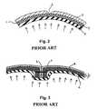
- FIG. 1shows a ball having a hole 5 for admitting inflating air, and leather panels 4 .
- FIGS. 2 to 4show sectional views of balls of different types taken along line A-A.
- FIG. 2illustrates a laminated ball.
- an adhesiveis coated on the nylon filament to prevent it from sliding off.
- the reinforcing layeritself has the functions of maintaining the spherical shape and resisting impact.
- Leather panels 4are attached to the reinforcing layer 3 using adhesive 11 to form the skin layer.
- the reinforcing layer 3can be covered with rubber.
- the leather panels 4 of the ballgenerally has 32 pieces including 12 pieces of regular pentagon and 20 pieces of regular hexagon.
- the material for the panelis genuine leather or artificial leather (with a thickness of 1.0-2.0 mm).
- the peripheral portion of the back of the leather panel 4is cut obliquely, and a V-shaped groove 6 is formed on a leather panel joint, so that the V-shaped panel groove 6 for suppressing air resistance and improving flying property is formed.
- the laminated ballhas an integral structure in which the bladder 2 , reinforcing layer 3 and leather panels 4 are attached to each other using adhesive.
- the arrowsrepresent the air pressure in the bladder 6 .
- Laminated balls with the above structurehave high quality, good sphericity and small errors in size and weight, because they can be produced in mechanized way. And the balls have excellent durability because the reinforcing layer is made of nylon filament.
- laminated ballshave some disadvantages.
- the panel grooves 6is too wide and too shallow, being approximately 8 mm in width and 1 mm in depth, so that air resistance is not sufficiently low.
- the disadvantagesalso include poor gripping property, hard tactility when kicked, and poor controlling properties, so that the balls can not be official game balls.
- FIG. 3illustrates a hand-stitched ball.
- an unattached bladder 2is accommodated in a skin pocket made of complex panels 9 , so that it is in a free state. After the air is inflated in, the bladder 2 , made of elastic rubber, is pressed against the inner surface of the complex panels 9 due to the inner air pressure (as indicated by arrows in FIG. 3 ).
- a leather panel 4 with a liner or buffering material attached to its backis generally referred to as a complex panel.
- the hand-stitched ballis generally formed in such a process that the liner material as the reinforcing layer 3 made of laminated 3-4 pieces of fabrics with adhesive is attached to the back of the leather panel 4 to form the complex panel 9 , the complex panels 9 are stitched together using a hand-stitching thread 7 (about 10000-denier thread) to form the ball shell having spherical shape, and the bladder 2 , the same as the one used in the above-mentioned laminated ball, is accommodated in the ball shell.
- the place where the complex panels 9 are stitchedis shown in FIG. 3 , and the bladder 2 has the same shape as that of the inner surface of the panels 9 after the ball is inflated.
- the leather panels 4are made of the same genuine or artificial leather as used in the laminated balls (with a thickness of 1.0-2.0 mm). The ball with this kind of structure is described in Japanese unexamined Patent Publication No. 19516/1997.
- the hand-stitched ballhas the following advantages.
- the ball's air resistanceis small, and its flying and gripping properties are excellent because the panel groove 6 is narrow and deep, being approximately 2.5 mm and 2 mm respectively.
- Tactilityis soft, and controllability is good because the reinforcing layer is made of fabrics. Hence, the hand-stitched balls are used in ball games in great quantities.
- a hand-stitched ballcan not be stitched using a sewing machine because of the three-dimensionality of the sphere and the thick and hard complex panels reinforced by the liner material. Therefore, the operators are required to have substantially the same familiarity and skills, otherwise the balls manufactured by different operators will have large differences. Moreover, there are the problems of low production efficiency, unstable quality and unacceptable differences in weight, size and sphericity because of the hand-stitching process.
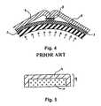
- FIG. 4illustrates a machine-stitched ball.
- a machine-stitched ballwhose skin layers are stitched using machinery, has a structure that combines the structures of the laminated ball and the stitched ball.
- the bladder 2 and the reinforcing layer 3have the same structures as the above-mentioned laminated ball, with a reinforcing layer 3 being used to maintain the spherical shape and ensure durability.
- the marginal edges of the leather panels 4are folded inward, and the leather panels 4 with the marginal edges are stitched together with machine-threads 8 (about 500-denier) into a spherical shape to form the skin layer. Then the integrated bladder 2 and reinforcing layer 3 are accommodated in the skin layer.
- the leather panel 4is made of the complex lamination leather comprising a TPU film (with a thickness of 0.10-0.50 mm) and an EVA foam (with the thickness of 1.0-5.0 mm), or made of artificial leather (with a thickness of 1.0-3.0 mm).
- a machine-stitched ball with the above structureis described in U.S. Pat. No. 5,772,545.
- the liner materialis not required on the back of the leather panels 4 because a reinforcing layer 3 exists on the bladder 2 , so that the leather panels 4 are so soft that they can be stitched using a sewing machine.
- the machine-stitched ballcan be produced in a mechanized way according to the above-mentioned structure and manufacturing method, so that machine-stitched balls have good quality, small errors in size and weight, and excellent durability.
- FIG. 4shows a stitched portion of the leather panels 4 .
- the stitched portionis lifted up by the reinforcing layer 3 attached to the bladder 2 , so that the leather panels 4 at this place become flat, thus, the sphericity of the ball is impaired. Therefore, the ball has irregular bounce and poor flying properties, it can not be used as an official ball for a ball game.
- a peripheral edge portion of the leather panel 4 with a thickness of 1.6-1.8 mmis folded in at a 90° (or 180°) angle, and the height difference due to this fold is eliminated by attaching a thickness adjusting member 10 with the thickness substantially equal to the height difference on the lower portion of the step (see FIG. 5 ).
- the manufacturing method of the inventionis described in detail in the description of this patent. That is, the leather panel 4 with the specified size (see FIG. 6( a )) and a thickness adjusting member 10 smaller than the leather panel 4 (see FIG. 6( b )) are cut, adhesive 11 (natural latex or adhesives of CR or PU series) is applied on the back side of the leather panel 4 and the lower surface of the thickness adjusting member 10 , and both the panel 4 and member 10 are laminated together, as shown in FIG. 6( c ). In this example, the adhesive is applied on the lateral side 15 of the thickness adjusting member 10 also. According to the above steps, a folding portion 12 , which can cover the lateral side 15 of the thickness adjusting member 10 , is formed along the entire periphery of the leather panel 4 .
- the folding portion 12is folded further to cover the lateral side 15 of the thickness adjusting member 10 and then attached to it (see FIG. 6( d )).
- the inventionon the basis of the thickness adjusting member 10 attached to the leather panel 4 has the following problems.
- this ballis used under harsher conditions. That is, the football or volleyball is frequently and repeatedly subjected to impact over 100 kgf when kicked or spiked. All parts of the ball may stay in a damp state for a long time because of rain or sweat. When played outdoors, the ball is often used in sand or mud. Especially in the summer the ball often encounters a high temperature over 40° C. whether in use or in storage. All these conditions significantly affect the attached portions of the ball. Frequently the leather panels peel off. In order to solve the above problem, the development of an excellent attaching technique is a great challenge in the art.
- the peeling off problemalso exists in the above example. This peeling off phenomenon results from following two causes. First, the adhesive force between the thickness adjusting member 10 and the leather panel 4 can not always be kept constant, because the air remains in some places when they are laminated, resulting in unattached areas. Moreover, it is likely that the adhesive is excessively dried or is beyond the effective hours.
- the adhesive force between the folding portion 12 and the lateral side 15 of the thickness adjusting member 10is weak.
- a strong adhesive forceresults from the correct adhesive, proper temperature and strong engaging pressure.
- the folding portion 12 folded in a 90° angleis just in contact with the lateral side 15 of the thickness adjusting member 10 , so that there is no pressure toward the lateral side. This problem becomes especially obvious when the thickness adjusting member 10 is made from a buffering material like sponge.
- the folding portion 12is separated from the lateral side 15 of the thickness adjusting member 10 , which becomes the beginning of separation and the separation will be developed all over the leather panels 4 .
- the adhesivemust be coated on both the thickness adjusting member 10 and the leather panel 4 , especially in the thickness adjusting member 10 , the adhesive must be coated on the lateral side 15 one by one. This is inefficient and time-consuming, resulting in high manufacturing cost.
- the present inventionis directed to solve these problems.
- the present inventioncan reduce the adhered portions and significantly increase the strength of the adhered portions, while reducing the risk of detachment, so that the above-mentioned problems are solved.
- the manufacturing process of the ball panelis significantly simplified and the manufacturing cost is reduced.
- One object of the inventionis to provide a panel of the ball for a ball game, simplify manufacturing process, lower production cost, and produce desired properties.
- Another object of the inventionis to provide a ball that comprises the above panels.
- a panel of the ball of the present inventionhas a folding portion and an opposite folding portion along its periphery, which are opposite each other and made from the same continuous material.
- the folding portion and the opposite folding potionare engaged with each other through an engaging layer.
- the engaging layeris composed of a melted layer of the panel member.
- the engaging layeris composed of an adhesive.
- the panelis composed in a laminated structure including a skin layer and a fold engaging material.
- adhesiveis coated in a teeth-shaped pattern on the side surface of the panel.
- a ball of the invention from the inside to the outside in sequencecomprises a bladder, a reinforcing layer and the panels of the ball.
- the panelsare adhered on the reinforcing layer directly or through a covered rubber layer.
- the folding portion of the panelis folded inwardly and then stitched to each other.
- the joint of the adjacent panelscan be connected with adhesive.
- the folding portion and the opposite folding portionare made of the same material, so that they have good engaging property and are difficult to separate during usage.
- itis unnecessary to coat adhesive one by one if the engaging layer is composed of the melted layer, so that the manufacturing process is simplified and production cost is reduced.
- a ballcomprising the above-mentioned panels has good properties, simplified manufacturing process and low production costs.
- the folding portionis folded inwardly and then stitched together, so that the sewing machine can be used to stitch the panels, improving production efficiency.
- the stitched portioncan not be lifted up as occurring in the prior art, so that the sphericity of the ball can be maintained, and the quality of the ball can be increased.
- FIG. 1shows a ball for a ball game.
- FIG. 2shows the structure of a laminated ball of the prior art, which is taken along A-A line in FIG. 1 .
- FIG. 3shows the structure of a hand-stitched ball of the prior art, which is taken along A-A line in FIG. 1 .
- FIG. 4shows the structure of a machine-stitched ball of the prior art, which is taken along A-A line in FIG. 1 .
- FIG. 5shows the structure of a leather panel of a ball of the international patent publication No. W099/61114, which is taken along A-A line in FIG. 1 .
- FIG. 6( a )- 6 ( d )show the manufacturing process of a leather panel of the ball of FIG. 5 .
- FIG. 7( a )- 7 ( l )show the structure of a leather panel of the present invention and its manufacturing process.
- FIG. 8( a )- 8 ( b )show a diagram of one method for laminating the leather panels of the present invention on a reinforcing layer, which is taken along A-A line in FIG. 1 .
- FIG. 9shows a diagram of another method for covering the reinforcing layer with the leather panels of the present invention, which is taken along A-A line in FIG. 1 .
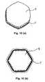
- FIG. 10( a )- 10 ( b )show a diagram of a side surface pattern of a leather panel of the present invention.
- FIG. 7shows the manufacturing process of a leather panel of the present invention.
- a skin materialis cut to form a leather panel 4 with the specified size.
- the leather panels of, for example, a footballcan consist of 32 pieces including 20 pieces of regular hexagon and 12 pieces of regular pentagon. It is possible to have other combinations, such as the combination of 12 pieces of regular pentagon or 20 pieces of regular triangular with 12 pieces of regular pentagon. That is, any shapes are possible so long as they can cover the entire sphere.
- the cross section of the leather panel 4is a rectangle.
- the leather panels 4is made of artificial leather with a thickness of 2 to 8 mm, preferably 3 to 5 mm.
- the main material of artificial leatheris polyurethane (PU) or polyvinyl chloride (PVC).
- Another kind of leather panelis made of a complex leather material comprising a thermal plastic polyurethane (TPU) film and a foam material such as ethylenevinyl acetate copolymer (EVA), polyethylene (PE), ethylene-propylene-diene ternary copolymer rubber (EPDM) and styrene-butadiene (SBR).
- EVAethylenevinyl acetate copolymer
- PEpolyethylene
- EPDMethylene-propylene-diene ternary copolymer rubber
- SBRstyrene-butadiene
- the periphery of the leather panel 4 as shown in FIG. 7( a )is processed to make the skin material have a T-shaped section.
- a folding portion 12will then be formed.
- the periphery of the leather panel 4can be processed using any of the following processing methods:
- the first methodis the high-frequency processing method.
- the periphery of the leather panel 4is pressed using an embossing die which has the same shape as the folding portion 12 with a voltage of several thousand volts and a high-frequency of tens thousand Hz. As shown in FIG. 7( b ), the periphery is compressed under the effect of the heat generated by the voltage and the high-frequency, and the folding portion 12 can be formed instantaneously, with the opposite folding portion 15 being formed simultaneously.
- the second methodis the hot plate processing method.
- the periphery of the leather panel 4is pressed using an embossing die which has the same shape as the folding portion 12 with the die temperature at 100-400° C. As shown in FIG. 7( b ), the periphery is pressed and melted to form the folding portion 12 , the opposite folding portion 15 being formed simultaneously.
- the hot plate processing methodcompletes its operation instantaneously.
- the selected range of temperaturedepends on embossing pressure, pressing duration and the panel material.
- the folding potion 12 and the opposite folding portion 15 processed using the above processing methodsare integrated as a whole. They are made of the same continuous material, rather than two materials attached with adhesive as is in the prior art (as shown in FIG. 6) .
- FIG. 7( c )shows the forming state of an engaging layer 14 for engaging the folding portion 12 with the opposite folding portion 15 .
- the engaging layer 14is formed using the following method. That is, in the high-frequency processing method and the hot plate processing method, a portion of the leather panel 4 , which is contacted by the embossing die, is melt by heat in the range of 0.1-1.0 mm in its direction. This portion will be the engaging layer 14 for engaging. This state will last 3-4 seconds after the embossing die is separated from the leather panel 4 , the following process being performed to obtain strong engagement during this 3-4 seconds.
- the leather panel 4is pressed into a mould 13 having a recess which has substantially the same shape as the final leather panel when the engaging layer 14 staying in the melting state, the folding portion 12 and the opposite folding portion 15 being engaged with each other through the engaging layer 14 in this process.
- the engaging layer 14is cooled down, the folding portion 12 and the opposite portion 15 are firmly attached together, finally forming the leather panel 4 as shown in FIG. 7( e ).
- the leather panel 4In the case of the high-frequency processing method and the hot plate processing method, the leather panel 4 must be pressed into the mould 13 within 3-5 seconds after the engaging layer 14 is formed, because, as described above, the engaging layer 14 should be in the melting state when these two portions are engaged.
- the folding portion 12is formed while the engaging layer 14 is formed simultaneously, so that the complicated process for coating adhesive on the engaging faces of all sides can be omitted, and the manufacturing cost can be substantially reduced.
- the pressing force applied from the folding portion 12 to the opposite folding portion 15is still very small.
- the folding portion 12 and the opposite folding portion 15are made of the same material, and the material molecules of both portions are mixed with each other after they are engaged in the melting state and cooled down. In this engagement, a large pressing force is unnecessary, because a smaller pressing force is enough to obtain very firm engagement. In a stretching test for an engaging portion, it was confirmed that the material of these portions is broken without separation of engagement.
- the following methodscan be used.
- a folding portion 12is obtained by placing a leather panel 4 on a rotating table to be rotated and cutting the periphery of the leather panel 4 with a sharp cutting-tool in horizontal and vertical directions at the same time, while the opposite folding portion 15 is obtained simultaneously.
- the cutting-tool used in the inventioncan be rotating circular cutting-tool or very small triangular cutting-tool.
- the folding portion 12must be processed one by one, the processing efficiency is lower than the above two methods, but this method is very effective for materials such as vulcanized rubbers and the like, which are unsuitable for the above two methods.
- the following methodscan be used also to process the periphery of the leather panel 4 .
- One of theseis the cold-pressing method.
- Compressed air (1 ⁇ 9 kg/cm 2 )is generally used in the high-frequency processing method and the hot plate processing method.
- the folding portion and the opposite folding portionare obtained by compressing the periphery of the leather panel with a high pressure (10 kg/cm 2 ⁇ 100 kg/cm 2 ) from the hydraulic press.
- the laser processing methodis another method.
- laseris used to generate heat to cut and melt the periphery of the leather panel.
- the cutting methodhas the same attaching process as the laminated ball discussed above. In the discussed example, however, different materials are attached with adhesive, while in the cutting method, the same material is stuck with the adhesive as an engaging layer 14 , so that the adhesive force between the folding portion 12 and the opposite folding portion 15 will be stronger, being similar to that in the high-frequency processing method and the hot plate processing method.
- the manufacturing costis increased, but this method is the only effective one with a relatively low cost for the materials unsuitable for the high-frequency processing method and the hot plate processing method.
- FIG. 7( h ), ( j ), ( l )show other structures of the leather panel 4 .
- the leather panels of the ballsare made from different materials according to the types of the balls, the requirements of the user, the conditions under which the balls are used and cost considerations. Some of these materials for the leather panel can not be used to obtain the engaging layer in the melting state using the high-frequency processing method and the hot plate processing method. Moreover, it is difficult to cut a material having a high adhering property if the cutting method is used. In this case, the above-mentioned problems can be solved by laminating some other materials to form an engaging layer.
- FIG. 7( f ) to FIG. 7( h )shows complex leather panels P obtained by attaching a fold engaging material 17 and a top skin material 16 with an adhesive such as natural latex, polyurethane, or the like.
- the top skin material 16(with a thickness of 1.0 ⁇ 2.0 mm) as the top layer is artificial leather (as described above) with the liner made of cotton/polyester blend fabric or a foam rubber material.
- An EVA foam layer with a thickness of 1.0 ⁇ 5.0 mmis used as a fold engaging material 17 . It is well known that cotton/polyester blend fabric and foam rubber can not be melted if the high-frequency processing method or the hot plate processing method is used. However, these two materials can be attached to an EVA foam material firmly with adhesive. On the other hand, the engaging layer 14 in melting state can be easily obtained from the EVA foam material using the high-frequency processing method or the hot plate processing method.
- FIG. 7( f )shows an example of the above complex leather panel P.
- the folding portion 12 and the opposite folding portion 15are obtained, while the engaging layer 14 is obtained simultaneously on the fold engaging material 17 using the high-frequency processing method or the hot plate processing method.
- the complex leather panel Pis pressed into the same mould 13 as that in FIG. 7( d ) when the engaging layer 14 stays in the melting state, and a complex leather panel P as shown in FIG. 7( h ) similar to the above example, whose periphery is folded, can be obtained after pressing and cooling.
- a main engaging portionexists between the folding portion 12 and the opposite folding portion 15 .
- the same continuous materialis melted and engaged if the high-frequency processing method or the hot plate processing method is especially used, so that a very firm engagement can be obtained.
- the adhered portionscan be substantially reduced if the cutting method is used, and the strong adhesive force can be ensured because the folding portion 12 and the opposite folding portion 15 are made of the same material, and the adhering effect of the same material can be excellently realized.
- the leather panel 4can have various structures described below.
- FIGS. 7( i ) and ( j )show another complex leather panel P to which a function assigning material 18 (which can assign a certain function to the panel) is attached.
- the function assigning material 18is laminated between the top skin material 16 and the fold engaging material 17 .
- a fabric of polyester and the like as a function assigning material 18can be provided between the skin material 16 and the fold engaging material 17 to form a leather panel having excellent durability.
- an SBR foam material having excellent silencing effect and softnesscan be used as a function assigning material 18 , making the ball have soft tactility and reduce the metallic impact sound when the ball is kicked.
- the function assigning material 18is very hard and to bend because of its rigidity, as shown in FIGS. 7( k ) and ( l ), the function assigning material 18 is cut into pieces smaller than the top skin material 16 , and the fold engaging material 17 is overlaid on the function assigning material 18 to form the complex leather panels P as shown in FIG. 7( l ).
- FIGS. 8 and 9show a diagram of a ball completed using leather panels 4 , and complex leather panels P, according to the invention, which is taken along line A-A in FIG. 1 .
- FIGS. 8( a ) and 8 ( b )show the examples of various leather panels suitable for the laminated ball.
- Leather panels 4 and complex leather panels Pare attached to each other with adhesive 11 on a reinforcing layer 3 directly or through covered rubber.
- the reinforcing layer 3can be formed by winding nylon filament around a bladder 2 , sewing a ball-shaped pocket with fabric or adhesive fabric on the bladder.
- Chloroprene (CR) base adhesive, polyurethane, natural latex and the likecan be used as adhesive.
- the panel grooves 6 having the same width and depth as the hand-stitched ball, being narrow and deep,can be obtained in the above-mentioned structure, so that air resistance can be reduced and the ball has the same flying properties as a hand-stitched ball.
- a ball manufactured by adhesive leather panels 4 and complex leather panels P of the present invention on a ball-shaped reinforcing layer 3 made of fabrichas the same properties in all aspects as a hand-stitched ball of the prior art. That is, the ball has soft tactility when kicked and excellent control property. Furthermore, the ball has the same flying and bounce properties as a hand-stitched ball. Being different from the hand-stitched ball, the leather panels 4 and complex leather panels P need not be stitched, so that durability is substantially improved. All these balls can be manufactured in mechanized way, so that mass-production with high quality and stable yield can be realized. The present invention has improved all aspects such as the quality, durability, properties and manufacturing cost, making a great contribution to the industry and the competition.
- FIG. 9shows an example of a machine-stitched ball.
- an engaging layer 14 as shown in FIG. 7( c )is not needed and the process for pressing the leather panel into the mould 14 is omitted. That is, a folding portion 12 of the leather panel 4 as shown in FIG. 7( b ) is folded inwardly and stitched with stitching threads 8 into the ball-shaped skin layer, and then a reinforcing layer or carcass 3 and a bladder 2 , which are integrated as a whole, are accommodated in the ball-shaped skin layer. According to this method, the folding portion 12 with a thickness that is half of the thickness of the leather panel 4 or lower is used as the stitching portion. As shown in FIG.
- the stitching portionis not beyond the thickness of the leather panel 4 , so that it will not be lifted by the reinforcing layer 3 , as is in the prior art, and the shape of the ball will not be affected.
- adhesive(not shown) is applied to the outer sides of the end faces of adjacent leather panels 4 or complex leather panels P to attach these side faces between the adjacent leather panels, so that water can be prevented from seeping into the ball. Therefore, the weight increase due to water seeping of the ball will not occur when used in rainy days, and the durability can be improved also.
- a ball made from the leather panels of the present inventionhas air resistance similar to that of a hand-stitched ball.
- slight roughness S shown in FIG. 10( a ) similar to a stitching seamcan be provided on the periphery surface of a leather panel 4 or complex leather panel P using high-frequency processing.
- Leather panels 4can be processed to have the rough periphery using the embossing method, that is, slight roughness S is processed using the high-frequency processing method or the hot plate pressing method before the folding process.
- the roughnesshas the same intervals as the stitches of a hand-stitched ball, preferred at 4 to 5 mm, and the preferred height at 0.5 to 1.5 mm.
- the appearance of the leather panel after foldingis shown in FIG. 10( a ).
- FIG. 10( b )shows another method for the same object.
- adhesiveis applied to teeth-shaped pattern T on the periphery of a leather panel 4 or a complex leather panel P.
- the patterncan have the same interval and height as the above example.
- the seam-shaped appearancecan be realized by engaging the concaves and the convexes of the teeth, which are coated with adhesive, with each other between the side faces of the adjacent leather panels when these leather panels are attached to the ball. The effect is equivalent to the hand-stitched ball, that is, the air resistance is reduced and the grasping property is improved.
- the leather panel 4 and complex leather panels P of the present inventionhave the following properties and advantages:
- the folding portion and the opposite folding portionare made of the same continuous material, and the engaging force is strong and the durability is improved.
Landscapes
- Health & Medical Sciences (AREA)
- General Health & Medical Sciences (AREA)
- Physical Education & Sports Medicine (AREA)
- Treatment And Processing Of Natural Fur Or Leather (AREA)
- Laminated Bodies (AREA)
- Pinball Game Machines (AREA)
Abstract
Description
Claims (14)
Priority Applications (2)
| Application Number | Priority Date | Filing Date | Title |
|---|---|---|---|
| US12/716,841US20100160096A1 (en) | 2004-08-25 | 2010-03-03 | Panel of a ball for a ball game, a ball, and methods of making the same |
| US12/717,654US20100154979A1 (en) | 2004-08-25 | 2010-03-04 | Panel of a ball for a ball game, a ball, and methods of making the same |
Applications Claiming Priority (3)
| Application Number | Priority Date | Filing Date | Title |
|---|---|---|---|
| CN200410068524.0 | 2004-08-25 | ||
| CN200410068524 | 2004-08-25 | ||
| CN200410068524.0ACN1739826B (en) | 2004-08-25 | 2004-08-25 | Method for manufacturing leather ball piece |
Related Child Applications (2)
| Application Number | Title | Priority Date | Filing Date |
|---|---|---|---|
| US12/716,841DivisionUS20100160096A1 (en) | 2004-08-25 | 2010-03-03 | Panel of a ball for a ball game, a ball, and methods of making the same |
| US12/717,654DivisionUS20100154979A1 (en) | 2004-08-25 | 2010-03-04 | Panel of a ball for a ball game, a ball, and methods of making the same |
Publications (2)
| Publication Number | Publication Date |
|---|---|
| US20060046880A1 US20060046880A1 (en) | 2006-03-02 |
| US7749116B2true US7749116B2 (en) | 2010-07-06 |
Family
ID=35944165
Family Applications (3)
| Application Number | Title | Priority Date | Filing Date |
|---|---|---|---|
| US11/017,718Expired - Fee RelatedUS7749116B2 (en) | 2004-08-25 | 2004-12-22 | Panel of a ball for a ball game, a ball, and methods of making the same |
| US12/716,841AbandonedUS20100160096A1 (en) | 2004-08-25 | 2010-03-03 | Panel of a ball for a ball game, a ball, and methods of making the same |
| US12/717,654AbandonedUS20100154979A1 (en) | 2004-08-25 | 2010-03-04 | Panel of a ball for a ball game, a ball, and methods of making the same |
Family Applications After (2)
| Application Number | Title | Priority Date | Filing Date |
|---|---|---|---|
| US12/716,841AbandonedUS20100160096A1 (en) | 2004-08-25 | 2010-03-03 | Panel of a ball for a ball game, a ball, and methods of making the same |
| US12/717,654AbandonedUS20100154979A1 (en) | 2004-08-25 | 2010-03-04 | Panel of a ball for a ball game, a ball, and methods of making the same |
Country Status (6)
| Country | Link |
|---|---|
| US (3) | US7749116B2 (en) |
| EP (1) | EP1680194B1 (en) |
| CN (1) | CN1739826B (en) |
| AT (1) | ATE530229T1 (en) |
| ES (1) | ES2378050T3 (en) |
| WO (1) | WO2006021140A1 (en) |
Cited By (25)
| Publication number | Priority date | Publication date | Assignee | Title |
|---|---|---|---|---|
| US20100144470A1 (en)* | 2008-12-05 | 2010-06-10 | Keng-Hsien Lin | Sporting article and method of making the same |
| US20100167850A1 (en)* | 2008-12-30 | 2010-07-01 | Long Way Enterprise Co., Ltd | Seamless ball structure |
| US20100240479A1 (en)* | 2009-03-20 | 2010-09-23 | Nike, Inc. | Sport Ball Casing And Methods Of Manufacturing The Casing |
| US20100255940A1 (en)* | 2009-04-03 | 2010-10-07 | Adidas Ag | Ball |
| US20110165979A1 (en)* | 2010-01-05 | 2011-07-07 | Nike, Inc. | Sport Balls And Methods Of Manufacturing The Sport Balls |
| US20120088614A1 (en)* | 2009-05-20 | 2012-04-12 | Puma SE | Method for producing a ball and ball |
| US20120231908A1 (en)* | 2011-03-09 | 2012-09-13 | Mikasa Corporation | Sports Ball |
| US20120258824A1 (en)* | 2008-06-27 | 2012-10-11 | Nike, Inc. | Sport Ball Casing And Methods Of Manufacturing The Casing |
| USD671706S1 (en)* | 2009-12-22 | 2012-12-04 | Eat the Ball Holding, GmbH | Bread product |
| US20120329587A1 (en)* | 2006-12-11 | 2012-12-27 | Tsung Ming Ou | Sports ball |
| US20140155203A1 (en)* | 2010-12-03 | 2014-06-05 | Nike, Inc. | Sport Ball With Indented Casing |
| US8777787B2 (en) | 2008-06-27 | 2014-07-15 | Nike, Inc. | Sport ball |
| US8926459B2 (en) | 2012-03-30 | 2015-01-06 | Nike, Inc. | Sport balls and methods of manufacturing the sport balls |
| US8974330B2 (en) | 2009-03-20 | 2015-03-10 | Nike, Inc. | Sport ball casing and methods of manufacturing the casing |
| US9084918B2 (en) | 2012-05-31 | 2015-07-21 | Nike, Inc. | Football with segmented cover panels |
| US9457239B2 (en) | 2008-06-27 | 2016-10-04 | Nike, Inc. | Sport ball casing with integrated bladder material |
| US9586098B1 (en) | 2016-01-12 | 2017-03-07 | Zain-Ul-Abideen Ahsan | Sports ball and method of manufacturing sports ball |
| EP3141290A1 (en) | 2015-09-11 | 2017-03-15 | Hideomi Shishido | Ball for ball games, and method for manufacturing ball for ball games |
| US9623289B2 (en) | 2013-02-27 | 2017-04-18 | Nike, Inc. | Method of inflatable game ball panel construction |
| US20170304685A1 (en)* | 2016-04-22 | 2017-10-26 | Silver Star Enterprises (Pvt.) Ltd. | DPS Sport Ball |
| US20180200969A1 (en)* | 2015-05-28 | 2018-07-19 | Adidas Ag | Panel for a ball |
| JP6433625B1 (en)* | 2017-08-01 | 2018-12-05 | 株式会社モルテン | ball |
| US10195493B2 (en)* | 2014-08-04 | 2019-02-05 | Trig Group, Llc | Multiple layer ball |
| WO2019026343A1 (en)* | 2017-08-01 | 2019-02-07 | 株式会社モルテン | Ball |
| US20190105540A1 (en)* | 2017-10-05 | 2019-04-11 | Anwar Khawaja Industries (Pvt) Limited | Sports Ball and Method of Manufacturing Sports Ball |
Families Citing this family (37)
| Publication number | Priority date | Publication date | Assignee | Title |
|---|---|---|---|---|
| EP1709998B1 (en)* | 2005-04-08 | 2011-07-13 | Goedoen Holding FZC | Sports ball with a woven fabric and method for manufacturing such a sports ball |
| US20060293132A1 (en)* | 2005-06-24 | 2006-12-28 | Russell Asset Management, Inc. | Football |
| USD539048S1 (en)* | 2005-09-28 | 2007-03-27 | Callegher Trading Ag | Chair seat |
| US8388476B2 (en)* | 2006-12-11 | 2013-03-05 | Tsung Ming Ou | Sports ball |
| USD603916S1 (en) | 2007-05-11 | 2009-11-10 | Nike, Inc. | Ball |
| USD558285S1 (en) | 2007-05-11 | 2007-12-25 | Nike, Inc. | Ball |
| US20090093327A1 (en)* | 2007-10-09 | 2009-04-09 | Russell Asset Management, Inc. | Youth oriented sportsballs |
| JP5336756B2 (en)* | 2008-04-17 | 2013-11-06 | 株式会社モルテン | ball |
| US7854672B2 (en)* | 2009-01-22 | 2010-12-21 | Yao-Jen Huang | Structure of ball |
| KR101131811B1 (en) | 2010-02-26 | 2012-03-30 | 신신상사 주식회사 | Pannel of ball for ball games and manufactturing method thereof |
| JP2013013798A (en)* | 2012-10-23 | 2013-01-24 | Molten Corp | Ball and method for manufacturing the same |
| TW201433336A (en)* | 2013-02-27 | 2014-09-01 | Yi-Li Luo | Toy ball |
| CN103170110A (en)* | 2013-03-22 | 2013-06-26 | 南京绎霖国际贸易有限公司 | Playing ball with flat joint and manufacture method thereof |
| JP2013144257A (en)* | 2013-05-01 | 2013-07-25 | Molten Corp | Ball |
| US9011621B1 (en)* | 2013-11-04 | 2015-04-21 | Ali Hasnain Hussain | Systems and methods for producing a ball |
| EP3088054B1 (en)* | 2013-12-27 | 2020-10-07 | Molten Corporation | Ball |
| US9802082B1 (en)* | 2014-08-28 | 2017-10-31 | Christopher J. Calandro | Textured sports ball |
| US8991033B1 (en)* | 2014-10-16 | 2015-03-31 | Ali Hasnain Hussain | Methods for producing a soccer ball |
| DE102015209795B4 (en) | 2015-05-28 | 2024-03-21 | Adidas Ag | Ball and process for its production |
| US20170050089A1 (en)* | 2015-08-17 | 2017-02-23 | 2nd Skull, LLC | Impact dissipating ball |
| DE102015223885B4 (en)* | 2015-12-01 | 2024-03-21 | Adidas Ag | ball |
| US10646752B2 (en)* | 2016-03-13 | 2020-05-12 | Butt Nouman Idris | Methods of manufacturing of tri-tech soccer ball |
| DK3485946T3 (en)* | 2016-07-12 | 2022-05-16 | Molten Corp | Ball |
| CN106474691A (en)* | 2016-10-26 | 2017-03-08 | 洞口县昌冠隆体育用品有限公司 | One bulb inner bag processing technique |
| US10201732B2 (en)* | 2016-12-14 | 2019-02-12 | Mohammed Ejaz Ahmed | Ball with domed panels |
| WO2018111950A1 (en)* | 2016-12-14 | 2018-06-21 | Ahmed Mohammed Ejaz | Ball with increased flexure |
| US10112082B2 (en)* | 2016-12-14 | 2018-10-30 | Mohammed Ejaz Ahmed | Ball with increased flexure |
| EP3687638A1 (en)* | 2017-09-27 | 2020-08-05 | Dhirmalani, Anand A. | Swervable ball |
| US10653923B2 (en)* | 2017-10-24 | 2020-05-19 | Tsung Ming Ou | Channelless basketball and manufacturing method thereof |
| TWI651117B (en)* | 2017-11-27 | 2019-02-21 | 三芳化學工業股份有限公司 | Sphere structure and manufacturing method thereof |
| TWI650159B (en)* | 2017-11-27 | 2019-02-11 | 三芳化學工業股份有限公司 | Sphere structure and manufacturing method thereof |
| CN109925683A (en)* | 2017-12-15 | 2019-06-25 | 三芳化学工业股份有限公司 | Sphere structure and its manufacturing method |
| CN110614773A (en)* | 2019-09-16 | 2019-12-27 | 东莞市硕科塑胶五金制品有限公司 | Manufacturing method of high-strength leather ball piece |
| CN112933558A (en)* | 2021-02-03 | 2021-06-11 | 天长市正牧铝业科技有限公司 | Ethylene-vinyl acetate copolymer sewn football and preparation process thereof |
| CN116392786B (en)* | 2023-04-13 | 2023-12-01 | 南通高桥体育用品有限公司 | Environment-friendly water-based glue machine-attached volleyball and production process thereof |
| US20250161761A1 (en)* | 2023-11-22 | 2025-05-22 | Mohammed E. Ahmed | Sports ball with improved water resistance |
| CN117861178A (en)* | 2024-02-02 | 2024-04-12 | 南京鼎辉体育科技发展有限公司 | Sports ball, shell and ball piece thereof |
Citations (41)
| Publication number | Priority date | Publication date | Assignee | Title |
|---|---|---|---|---|
| US790041A (en)* | 1904-02-03 | 1905-05-16 | Albert Englerth | Game-ball. |
| US1187029A (en) | 1916-02-07 | 1916-06-13 | James L Beebout | Basket-ball and similar playing-ball. |
| US1502784A (en)* | 1923-10-18 | 1924-07-29 | Kennedy Bert | Baseball cover |
| US1861157A (en)* | 1930-03-01 | 1932-05-31 | J H Grady Mfg Company | Ball |
| US1923236A (en) | 1929-04-30 | 1933-08-22 | P Goldsmith Sons Company | Game ball |
| US1980472A (en)* | 1929-07-15 | 1934-11-13 | Hugh K Wagner | Ball |
| US2080894A (en)* | 1936-11-04 | 1937-05-18 | Levinson David | Inflatable ball |
| US2240256A (en)* | 1938-12-05 | 1941-04-29 | Elmendorf Armin | Box and corner construction therefor |
| US3119618A (en) | 1959-05-27 | 1964-01-28 | Spalding A G & Bros Inc | Inflated game ball |
| US3940142A (en)* | 1974-11-29 | 1976-02-24 | Ideal Toy Corporation | Fold up die construction |
| US4333648A (en) | 1979-02-06 | 1982-06-08 | Molten Rubber Industry Co., Ltd. | Inflatable game ball |
| US4462590A (en)* | 1982-10-22 | 1984-07-31 | Figgie International Inc. | Inflatable padded game ball |
| JPS61127764A (en) | 1984-11-26 | 1986-06-16 | Shin Etsu Chem Co Ltd | Method for producing organic polymer crosslinked product |
| US4660831A (en) | 1985-09-16 | 1987-04-28 | Figgie International Inc. | Inflatable padded game ball |
| US4856781A (en) | 1986-01-16 | 1989-08-15 | Molten Corporation | Game ball |
| US4874341A (en)* | 1988-10-25 | 1989-10-17 | Novation Design Ltd. | Folding polygonal toy construction element |
| JPH055157A (en) | 1990-11-21 | 1993-01-14 | Nippon Steel Corp | Electric resistance welded steel pipe for machine structure with excellent machinability |
| JPH06334459A (en) | 1993-05-18 | 1994-12-02 | Yamaha Corp | Digital signal processor |
| JPH08252341A (en) | 1995-03-14 | 1996-10-01 | Mizuno Corp | Ball for ball games |
| US5580049A (en)* | 1995-06-22 | 1996-12-03 | Lisco, Inc. | Soccer ball with fiber reinforced polyurethane cover |
| JPH0919516A (en) | 1995-07-05 | 1997-01-21 | Molten Corp | Ball for ball game |
| US5683317A (en)* | 1995-06-30 | 1997-11-04 | Lisco, Inc. | Automated lacing for softballs and baseballs |
| US5752890A (en) | 1994-05-10 | 1998-05-19 | Molten Corporation | Ball for ball game and method for manufacturing the same |
| US5759123A (en) | 1996-12-24 | 1998-06-02 | Ou; Tsung Ming | Sewing rubber american football and manufacturing method therof |
| US5772545A (en) | 1996-12-20 | 1998-06-30 | Ou; Tsung Ming | Sportsball and manufacturing method thereof |
| JPH10323409A (en) | 1997-03-24 | 1998-12-08 | Lisco Inc | Sport ball |
| US5860650A (en)* | 1993-11-03 | 1999-01-19 | Distribution Muralex Inc. | Three dimensional puzzle |
| WO1999061114A1 (en) | 1998-05-22 | 1999-12-02 | Molten Corporation | Ball game ball |
| US6022283A (en) | 1995-05-12 | 2000-02-08 | Schindler; Edgar C. | Inflatable ball |
| JP3010612B2 (en) | 1992-08-06 | 2000-02-21 | 日立電線株式会社 | Optical fiber cable connection |
| US6039662A (en) | 1998-04-21 | 2000-03-21 | Joyful Long International Ltd. | Inflatable stitched sports ball and method of making same |
| US6099423A (en) | 1999-02-11 | 2000-08-08 | Top Ball Trading Co., Ltd. | Basketball |
| US6206795B1 (en) | 1999-07-28 | 2001-03-27 | Tsung Ming Ou | Basketball with cushion layers |
| US6302815B1 (en) | 1997-09-22 | 2001-10-16 | Molten Corporation | Ball for a ball game |
| US6402647B1 (en)* | 1999-02-25 | 2002-06-11 | Arthur S. Haseltine | Kick-strengthening soccer practice ball, and production and training |
| US6656067B2 (en) | 1996-12-20 | 2003-12-02 | Tsung Ming Ou | Sportsball |
| US6726583B1 (en)* | 2003-02-13 | 2004-04-27 | Ye Gin Enterprise, Co., Ltd. | Game ball |
| US6767301B2 (en)* | 2002-07-25 | 2004-07-27 | Liang-Fa Hu | Enhancing inner structure of inflating ball with outer layer |
| US20050136793A1 (en)* | 2003-12-18 | 2005-06-23 | Strunk Linda M. | Collapsible play box |
| US6971965B1 (en)* | 2000-05-01 | 2005-12-06 | Molten Corporation | Ball for ball game and method for manufacturing the same |
| JP3816729B2 (en) | 2000-07-04 | 2006-08-30 | ダイハツ工業株式会社 | Rear suspension |
Family Cites Families (5)
| Publication number | Priority date | Publication date | Assignee | Title |
|---|---|---|---|---|
| US3791290A (en)* | 1972-01-07 | 1974-02-12 | G Colledge | High speed, high temperature embossing machine and wheel therefor |
| US4871341A (en)* | 1988-11-04 | 1989-10-03 | National Child Safety Council | Puppet mouth construction |
| US6500081B1 (en)* | 1999-05-17 | 2002-12-31 | Shyi-Ming Chen | Curve enhancing stitched baseball and softball |
| US6663520B2 (en)* | 2001-10-15 | 2003-12-16 | Li Chin Ou Chen | Stitching ball with intermediate construction ball pocket |
| DE10255092B4 (en)* | 2002-11-26 | 2010-11-11 | Molten Corp. | Method for producing parts of a ball |
- 2004
- 2004-08-25CNCN200410068524.0Apatent/CN1739826B/ennot_activeExpired - Fee Related
- 2004-12-22USUS11/017,718patent/US7749116B2/ennot_activeExpired - Fee Related
- 2005
- 2005-08-08ATAT05774393Tpatent/ATE530229T1/ennot_activeIP Right Cessation
- 2005-08-08ESES05774393Tpatent/ES2378050T3/ennot_activeExpired - Lifetime
- 2005-08-08WOPCT/CN2005/001217patent/WO2006021140A1/enactiveApplication Filing
- 2005-08-08EPEP05774393Apatent/EP1680194B1/ennot_activeExpired - Lifetime
- 2010
- 2010-03-03USUS12/716,841patent/US20100160096A1/ennot_activeAbandoned
- 2010-03-04USUS12/717,654patent/US20100154979A1/ennot_activeAbandoned
Patent Citations (45)
| Publication number | Priority date | Publication date | Assignee | Title |
|---|---|---|---|---|
| US790041A (en)* | 1904-02-03 | 1905-05-16 | Albert Englerth | Game-ball. |
| US1187029A (en) | 1916-02-07 | 1916-06-13 | James L Beebout | Basket-ball and similar playing-ball. |
| US1502784A (en)* | 1923-10-18 | 1924-07-29 | Kennedy Bert | Baseball cover |
| US1923236A (en) | 1929-04-30 | 1933-08-22 | P Goldsmith Sons Company | Game ball |
| US1980472A (en)* | 1929-07-15 | 1934-11-13 | Hugh K Wagner | Ball |
| US1861157A (en)* | 1930-03-01 | 1932-05-31 | J H Grady Mfg Company | Ball |
| US2080894A (en)* | 1936-11-04 | 1937-05-18 | Levinson David | Inflatable ball |
| US2240256A (en)* | 1938-12-05 | 1941-04-29 | Elmendorf Armin | Box and corner construction therefor |
| US3119618A (en) | 1959-05-27 | 1964-01-28 | Spalding A G & Bros Inc | Inflated game ball |
| US3940142A (en)* | 1974-11-29 | 1976-02-24 | Ideal Toy Corporation | Fold up die construction |
| US4333648A (en) | 1979-02-06 | 1982-06-08 | Molten Rubber Industry Co., Ltd. | Inflatable game ball |
| US4462590A (en)* | 1982-10-22 | 1984-07-31 | Figgie International Inc. | Inflatable padded game ball |
| JPS61127764A (en) | 1984-11-26 | 1986-06-16 | Shin Etsu Chem Co Ltd | Method for producing organic polymer crosslinked product |
| US4660831A (en) | 1985-09-16 | 1987-04-28 | Figgie International Inc. | Inflatable padded game ball |
| US4856781A (en) | 1986-01-16 | 1989-08-15 | Molten Corporation | Game ball |
| US4874341A (en)* | 1988-10-25 | 1989-10-17 | Novation Design Ltd. | Folding polygonal toy construction element |
| JPH055157A (en) | 1990-11-21 | 1993-01-14 | Nippon Steel Corp | Electric resistance welded steel pipe for machine structure with excellent machinability |
| JP3010612B2 (en) | 1992-08-06 | 2000-02-21 | 日立電線株式会社 | Optical fiber cable connection |
| JPH06334459A (en) | 1993-05-18 | 1994-12-02 | Yamaha Corp | Digital signal processor |
| US5860650A (en)* | 1993-11-03 | 1999-01-19 | Distribution Muralex Inc. | Three dimensional puzzle |
| US5752890A (en) | 1994-05-10 | 1998-05-19 | Molten Corporation | Ball for ball game and method for manufacturing the same |
| JPH08252341A (en) | 1995-03-14 | 1996-10-01 | Mizuno Corp | Ball for ball games |
| US6022283A (en) | 1995-05-12 | 2000-02-08 | Schindler; Edgar C. | Inflatable ball |
| US5580049A (en)* | 1995-06-22 | 1996-12-03 | Lisco, Inc. | Soccer ball with fiber reinforced polyurethane cover |
| US5683317A (en)* | 1995-06-30 | 1997-11-04 | Lisco, Inc. | Automated lacing for softballs and baseballs |
| JPH0919516A (en) | 1995-07-05 | 1997-01-21 | Molten Corp | Ball for ball game |
| US5772545A (en) | 1996-12-20 | 1998-06-30 | Ou; Tsung Ming | Sportsball and manufacturing method thereof |
| US6656067B2 (en) | 1996-12-20 | 2003-12-02 | Tsung Ming Ou | Sportsball |
| US6390941B1 (en) | 1996-12-20 | 2002-05-21 | Tsung Ming Ou | Sportsball |
| US5759123A (en) | 1996-12-24 | 1998-06-02 | Ou; Tsung Ming | Sewing rubber american football and manufacturing method therof |
| JPH10323409A (en) | 1997-03-24 | 1998-12-08 | Lisco Inc | Sport ball |
| US6302815B1 (en) | 1997-09-22 | 2001-10-16 | Molten Corporation | Ball for a ball game |
| US6039662A (en) | 1998-04-21 | 2000-03-21 | Joyful Long International Ltd. | Inflatable stitched sports ball and method of making same |
| US6220979B1 (en) | 1998-04-21 | 2001-04-24 | Chong Veng Chan | Inflatable stitched sports ball and method of making same |
| WO1999061114A1 (en) | 1998-05-22 | 1999-12-02 | Molten Corporation | Ball game ball |
| US6503162B1 (en) | 1998-05-22 | 2003-01-07 | Adidas International B.V. | Ball game ball |
| US6685585B2 (en) | 1998-05-22 | 2004-02-03 | Adidas International B.V. | Ball for ball game |
| US6099423A (en) | 1999-02-11 | 2000-08-08 | Top Ball Trading Co., Ltd. | Basketball |
| US6402647B1 (en)* | 1999-02-25 | 2002-06-11 | Arthur S. Haseltine | Kick-strengthening soccer practice ball, and production and training |
| US6206795B1 (en) | 1999-07-28 | 2001-03-27 | Tsung Ming Ou | Basketball with cushion layers |
| US6971965B1 (en)* | 2000-05-01 | 2005-12-06 | Molten Corporation | Ball for ball game and method for manufacturing the same |
| JP3816729B2 (en) | 2000-07-04 | 2006-08-30 | ダイハツ工業株式会社 | Rear suspension |
| US6767301B2 (en)* | 2002-07-25 | 2004-07-27 | Liang-Fa Hu | Enhancing inner structure of inflating ball with outer layer |
| US6726583B1 (en)* | 2003-02-13 | 2004-04-27 | Ye Gin Enterprise, Co., Ltd. | Game ball |
| US20050136793A1 (en)* | 2003-12-18 | 2005-06-23 | Strunk Linda M. | Collapsible play box |
Cited By (50)
| Publication number | Priority date | Publication date | Assignee | Title |
|---|---|---|---|---|
| US20120329587A1 (en)* | 2006-12-11 | 2012-12-27 | Tsung Ming Ou | Sports ball |
| US20120258824A1 (en)* | 2008-06-27 | 2012-10-11 | Nike, Inc. | Sport Ball Casing And Methods Of Manufacturing The Casing |
| US8708847B2 (en)* | 2008-06-27 | 2014-04-29 | Nike, Inc. | Sport ball casing and methods of manufacturing the casing |
| US9457239B2 (en) | 2008-06-27 | 2016-10-04 | Nike, Inc. | Sport ball casing with integrated bladder material |
| US8777787B2 (en) | 2008-06-27 | 2014-07-15 | Nike, Inc. | Sport ball |
| US9457525B2 (en) | 2008-06-27 | 2016-10-04 | Nike, Inc. | Sport ball casing and methods of manufacturing the casing |
| US20100144470A1 (en)* | 2008-12-05 | 2010-06-10 | Keng-Hsien Lin | Sporting article and method of making the same |
| US20100167850A1 (en)* | 2008-12-30 | 2010-07-01 | Long Way Enterprise Co., Ltd | Seamless ball structure |
| US20110220279A1 (en)* | 2009-03-20 | 2011-09-15 | Nike, Inc. | Sport Ball Casing And Methods Of Manufacturing The Casing |
| US9821195B2 (en)* | 2009-03-20 | 2017-11-21 | Nike, Inc. | Sport ball casing and methods of manufacturing the casing |
| US8262519B2 (en) | 2009-03-20 | 2012-09-11 | Nike, Inc. | Sport ball casing and methods of manufacturing the casing |
| US20160206930A1 (en)* | 2009-03-20 | 2016-07-21 | Nike, Inc. | Sport ball casing and methods of manufacturing the casing |
| US9327167B2 (en) | 2009-03-20 | 2016-05-03 | Nike, Inc. | Sport ball casing and methods of manufacturing the casing |
| US8974330B2 (en) | 2009-03-20 | 2015-03-10 | Nike, Inc. | Sport ball casing and methods of manufacturing the casing |
| US8608599B2 (en)* | 2009-03-20 | 2013-12-17 | Nike, Inc. | Sport ball casing and methods of manufacturing the casing |
| US20100240479A1 (en)* | 2009-03-20 | 2010-09-23 | Nike, Inc. | Sport Ball Casing And Methods Of Manufacturing The Casing |
| US9539473B2 (en) | 2009-03-20 | 2017-01-10 | Nike, Inc. | Sport ball casing and methods of manufacturing the casing |
| US8529386B2 (en) | 2009-04-03 | 2013-09-10 | Adidas Ag | Ball |
| US20100255940A1 (en)* | 2009-04-03 | 2010-10-07 | Adidas Ag | Ball |
| US20120088614A1 (en)* | 2009-05-20 | 2012-04-12 | Puma SE | Method for producing a ball and ball |
| US8382619B2 (en)* | 2009-05-20 | 2013-02-26 | Puma SE | Method for producing a ball and ball |
| USD671708S1 (en) | 2009-12-22 | 2012-12-04 | Eat the Ball Holding GmbH | Bread product |
| USD671707S1 (en) | 2009-12-22 | 2012-12-04 | Eat the Ball Holding GmbH | Bread product |
| USD671706S1 (en)* | 2009-12-22 | 2012-12-04 | Eat the Ball Holding, GmbH | Bread product |
| US9814941B2 (en) | 2010-01-05 | 2017-11-14 | Nike, Inc. | Sport balls and methods of manufacturing the sport balls |
| US8579743B2 (en)* | 2010-01-05 | 2013-11-12 | Nike, Inc. | Sport balls and methods of manufacturing the sport balls |
| US20110165979A1 (en)* | 2010-01-05 | 2011-07-07 | Nike, Inc. | Sport Balls And Methods Of Manufacturing The Sport Balls |
| US9254424B2 (en)* | 2010-12-03 | 2016-02-09 | Nike Inc. | Sport ball with indented casing |
| US20140155203A1 (en)* | 2010-12-03 | 2014-06-05 | Nike, Inc. | Sport Ball With Indented Casing |
| US8672783B2 (en)* | 2011-03-09 | 2014-03-18 | Mikasa Corporation | Sports ball |
| US20120231908A1 (en)* | 2011-03-09 | 2012-09-13 | Mikasa Corporation | Sports Ball |
| US8926459B2 (en) | 2012-03-30 | 2015-01-06 | Nike, Inc. | Sport balls and methods of manufacturing the sport balls |
| US9884227B2 (en) | 2012-03-30 | 2018-02-06 | Nike, Inc. | Sport balls and methods of manufacturing the sport balls |
| US9084918B2 (en) | 2012-05-31 | 2015-07-21 | Nike, Inc. | Football with segmented cover panels |
| US9387367B2 (en) | 2012-05-31 | 2016-07-12 | Nike Inc. | Football with segmented cover panels |
| US9623289B2 (en) | 2013-02-27 | 2017-04-18 | Nike, Inc. | Method of inflatable game ball panel construction |
| US10195493B2 (en)* | 2014-08-04 | 2019-02-05 | Trig Group, Llc | Multiple layer ball |
| US20180200969A1 (en)* | 2015-05-28 | 2018-07-19 | Adidas Ag | Panel for a ball |
| US11724470B2 (en)* | 2015-05-28 | 2023-08-15 | Adidas Ag | Panel for a ball |
| US9682286B2 (en) | 2015-09-11 | 2017-06-20 | Hideomi Shishido | Ball for ball games, and method for manufacturing ball for ball games |
| EP3141290A1 (en) | 2015-09-11 | 2017-03-15 | Hideomi Shishido | Ball for ball games, and method for manufacturing ball for ball games |
| US9586098B1 (en) | 2016-01-12 | 2017-03-07 | Zain-Ul-Abideen Ahsan | Sports ball and method of manufacturing sports ball |
| US9844705B2 (en) | 2016-01-12 | 2017-12-19 | Zain-Ul-Abideen Ahsan | Sports ball and method of manufacturing sports ball |
| US20170304685A1 (en)* | 2016-04-22 | 2017-10-26 | Silver Star Enterprises (Pvt.) Ltd. | DPS Sport Ball |
| JP6433625B1 (en)* | 2017-08-01 | 2018-12-05 | 株式会社モルテン | ball |
| WO2019026343A1 (en)* | 2017-08-01 | 2019-02-07 | 株式会社モルテン | Ball |
| US12172055B2 (en) | 2017-08-01 | 2024-12-24 | Molten Corporation | Ball |
| US20190105540A1 (en)* | 2017-10-05 | 2019-04-11 | Anwar Khawaja Industries (Pvt) Limited | Sports Ball and Method of Manufacturing Sports Ball |
| EP3473306A1 (en) | 2017-10-05 | 2019-04-24 | Anwar Khawaja Industries (Pvt) Limited | Sports ball and method of manufacturing sports ball |
| US10632346B2 (en)* | 2017-10-05 | 2020-04-28 | Anwar Khawaja Industries Pvt. Ltd. | Sports ball and method of manufacturing sports ball |
Also Published As
| Publication number | Publication date |
|---|---|
| US20100154979A1 (en) | 2010-06-24 |
| US20060046880A1 (en) | 2006-03-02 |
| EP1680194A4 (en) | 2008-11-26 |
| US20100160096A1 (en) | 2010-06-24 |
| EP1680194A1 (en) | 2006-07-19 |
| EP1680194B1 (en) | 2011-10-26 |
| CN1739826A (en) | 2006-03-01 |
| CN1739826B (en) | 2014-11-19 |
| ATE530229T1 (en) | 2011-11-15 |
| WO2006021140A1 (en) | 2006-03-02 |
| ES2378050T3 (en) | 2012-04-04 |
Similar Documents
| Publication | Publication Date | Title |
|---|---|---|
| US7749116B2 (en) | Panel of a ball for a ball game, a ball, and methods of making the same | |
| EP2726163B1 (en) | Sport ball casing and methods of manufacturing the casing | |
| US9814941B2 (en) | Sport balls and methods of manufacturing the sport balls | |
| JP4157023B2 (en) | Method for producing ball components and method for producing balls | |
| US9457239B2 (en) | Sport ball casing with integrated bladder material | |
| EP2408527B1 (en) | Sport ball casing and methods of manufacturing the casing | |
| US7645203B2 (en) | Game ball carcass, a game ball, and methods of making same | |
| US20040087396A1 (en) | Sports balls | |
| EP3112003B1 (en) | Sport ball casing with integrated bladder material | |
| US7503861B2 (en) | Sportsball and method of manufacturing same | |
| US20100029420A1 (en) | Football and Method for Manufacturing Same | |
| WO2009065302A1 (en) | Bladder of sports ball and sports ball with the bladder |
Legal Events
| Date | Code | Title | Description |
|---|---|---|---|
| STCF | Information on status: patent grant | Free format text:PATENTED CASE | |
| AS | Assignment | Owner name:CHANG, FRANK,HONG KONG Free format text:ASSIGNMENT OF ASSIGNORS INTEREST;ASSIGNORS:TANG, YA FANG;CHANG, MARGARET YUEN YUEN;REEL/FRAME:024607/0646 Effective date:20100629 Owner name:CHANG, FRANK, HONG KONG Free format text:ASSIGNMENT OF ASSIGNORS INTEREST;ASSIGNORS:TANG, YA FANG;CHANG, MARGARET YUEN YUEN;REEL/FRAME:024607/0646 Effective date:20100629 | |
| FPAY | Fee payment | Year of fee payment:4 | |
| AS | Assignment | Owner name:FORCE TECH CO., LTD., CAYMAN ISLANDS Free format text:ASSIGNMENT OF ASSIGNORS INTEREST;ASSIGNOR:CHANG, FRANK;REEL/FRAME:043380/0339 Effective date:20170731 | |
| FEPP | Fee payment procedure | Free format text:PAT HOLDER NO LONGER CLAIMS SMALL ENTITY STATUS, ENTITY STATUS SET TO UNDISCOUNTED (ORIGINAL EVENT CODE: STOL) | |
| MAFP | Maintenance fee payment | Free format text:PAYMENT OF MAINTENANCE FEE, 8TH YEAR, LARGE ENTITY (ORIGINAL EVENT CODE: M1552) Year of fee payment:8 | |
| FEPP | Fee payment procedure | Free format text:MAINTENANCE FEE REMINDER MAILED (ORIGINAL EVENT CODE: REM.); ENTITY STATUS OF PATENT OWNER: LARGE ENTITY | |
| LAPS | Lapse for failure to pay maintenance fees | Free format text:PATENT EXPIRED FOR FAILURE TO PAY MAINTENANCE FEES (ORIGINAL EVENT CODE: EXP.); ENTITY STATUS OF PATENT OWNER: LARGE ENTITY | |
| STCH | Information on status: patent discontinuation | Free format text:PATENT EXPIRED DUE TO NONPAYMENT OF MAINTENANCE FEES UNDER 37 CFR 1.362 | |
| FP | Lapsed due to failure to pay maintenance fee | Effective date:20220706 |