US7747739B2 - Connection locator in a power aggregation system for distributed electric resources - Google Patents
Connection locator in a power aggregation system for distributed electric resourcesDownload PDFInfo
- Publication number
- US7747739B2 US7747739B2US11/836,747US83674707AUS7747739B2US 7747739 B2US7747739 B2US 7747739B2US 83674707 AUS83674707 AUS 83674707AUS 7747739 B2US7747739 B2US 7747739B2
- Authority
- US
- United States
- Prior art keywords
- power
- electric
- grid
- resource
- location
- Prior art date
- Legal status (The legal status is an assumption and is not a legal conclusion. Google has not performed a legal analysis and makes no representation as to the accuracy of the status listed.)
- Active, expires
Links
Images


Classifications
- B—PERFORMING OPERATIONS; TRANSPORTING
- B60—VEHICLES IN GENERAL
- B60L—PROPULSION OF ELECTRICALLY-PROPELLED VEHICLES; SUPPLYING ELECTRIC POWER FOR AUXILIARY EQUIPMENT OF ELECTRICALLY-PROPELLED VEHICLES; ELECTRODYNAMIC BRAKE SYSTEMS FOR VEHICLES IN GENERAL; MAGNETIC SUSPENSION OR LEVITATION FOR VEHICLES; MONITORING OPERATING VARIABLES OF ELECTRICALLY-PROPELLED VEHICLES; ELECTRIC SAFETY DEVICES FOR ELECTRICALLY-PROPELLED VEHICLES
- B60L3/00—Electric devices on electrically-propelled vehicles for safety purposes; Monitoring operating variables, e.g. speed, deceleration or energy consumption
- B60L3/12—Recording operating variables ; Monitoring of operating variables
- B—PERFORMING OPERATIONS; TRANSPORTING
- B60—VEHICLES IN GENERAL
- B60L—PROPULSION OF ELECTRICALLY-PROPELLED VEHICLES; SUPPLYING ELECTRIC POWER FOR AUXILIARY EQUIPMENT OF ELECTRICALLY-PROPELLED VEHICLES; ELECTRODYNAMIC BRAKE SYSTEMS FOR VEHICLES IN GENERAL; MAGNETIC SUSPENSION OR LEVITATION FOR VEHICLES; MONITORING OPERATING VARIABLES OF ELECTRICALLY-PROPELLED VEHICLES; ELECTRIC SAFETY DEVICES FOR ELECTRICALLY-PROPELLED VEHICLES
- B60L53/00—Methods of charging batteries, specially adapted for electric vehicles; Charging stations or on-board charging equipment therefor; Exchange of energy storage elements in electric vehicles
- B60L53/10—Methods of charging batteries, specially adapted for electric vehicles; Charging stations or on-board charging equipment therefor; Exchange of energy storage elements in electric vehicles characterised by the energy transfer between the charging station and the vehicle
- B60L53/14—Conductive energy transfer
- B—PERFORMING OPERATIONS; TRANSPORTING
- B60—VEHICLES IN GENERAL
- B60L—PROPULSION OF ELECTRICALLY-PROPELLED VEHICLES; SUPPLYING ELECTRIC POWER FOR AUXILIARY EQUIPMENT OF ELECTRICALLY-PROPELLED VEHICLES; ELECTRODYNAMIC BRAKE SYSTEMS FOR VEHICLES IN GENERAL; MAGNETIC SUSPENSION OR LEVITATION FOR VEHICLES; MONITORING OPERATING VARIABLES OF ELECTRICALLY-PROPELLED VEHICLES; ELECTRIC SAFETY DEVICES FOR ELECTRICALLY-PROPELLED VEHICLES
- B60L53/00—Methods of charging batteries, specially adapted for electric vehicles; Charging stations or on-board charging equipment therefor; Exchange of energy storage elements in electric vehicles
- B60L53/30—Constructional details of charging stations
- B60L53/305—Communication interfaces
- B—PERFORMING OPERATIONS; TRANSPORTING
- B60—VEHICLES IN GENERAL
- B60L—PROPULSION OF ELECTRICALLY-PROPELLED VEHICLES; SUPPLYING ELECTRIC POWER FOR AUXILIARY EQUIPMENT OF ELECTRICALLY-PROPELLED VEHICLES; ELECTRODYNAMIC BRAKE SYSTEMS FOR VEHICLES IN GENERAL; MAGNETIC SUSPENSION OR LEVITATION FOR VEHICLES; MONITORING OPERATING VARIABLES OF ELECTRICALLY-PROPELLED VEHICLES; ELECTRIC SAFETY DEVICES FOR ELECTRICALLY-PROPELLED VEHICLES
- B60L53/00—Methods of charging batteries, specially adapted for electric vehicles; Charging stations or on-board charging equipment therefor; Exchange of energy storage elements in electric vehicles
- B60L53/60—Monitoring or controlling charging stations
- B60L53/63—Monitoring or controlling charging stations in response to network capacity
- B—PERFORMING OPERATIONS; TRANSPORTING
- B60—VEHICLES IN GENERAL
- B60L—PROPULSION OF ELECTRICALLY-PROPELLED VEHICLES; SUPPLYING ELECTRIC POWER FOR AUXILIARY EQUIPMENT OF ELECTRICALLY-PROPELLED VEHICLES; ELECTRODYNAMIC BRAKE SYSTEMS FOR VEHICLES IN GENERAL; MAGNETIC SUSPENSION OR LEVITATION FOR VEHICLES; MONITORING OPERATING VARIABLES OF ELECTRICALLY-PROPELLED VEHICLES; ELECTRIC SAFETY DEVICES FOR ELECTRICALLY-PROPELLED VEHICLES
- B60L53/00—Methods of charging batteries, specially adapted for electric vehicles; Charging stations or on-board charging equipment therefor; Exchange of energy storage elements in electric vehicles
- B60L53/60—Monitoring or controlling charging stations
- B60L53/64—Optimising energy costs, e.g. responding to electricity rates
- B—PERFORMING OPERATIONS; TRANSPORTING
- B60—VEHICLES IN GENERAL
- B60L—PROPULSION OF ELECTRICALLY-PROPELLED VEHICLES; SUPPLYING ELECTRIC POWER FOR AUXILIARY EQUIPMENT OF ELECTRICALLY-PROPELLED VEHICLES; ELECTRODYNAMIC BRAKE SYSTEMS FOR VEHICLES IN GENERAL; MAGNETIC SUSPENSION OR LEVITATION FOR VEHICLES; MONITORING OPERATING VARIABLES OF ELECTRICALLY-PROPELLED VEHICLES; ELECTRIC SAFETY DEVICES FOR ELECTRICALLY-PROPELLED VEHICLES
- B60L53/00—Methods of charging batteries, specially adapted for electric vehicles; Charging stations or on-board charging equipment therefor; Exchange of energy storage elements in electric vehicles
- B60L53/60—Monitoring or controlling charging stations
- B60L53/65—Monitoring or controlling charging stations involving identification of vehicles or their battery types
- B—PERFORMING OPERATIONS; TRANSPORTING
- B60—VEHICLES IN GENERAL
- B60L—PROPULSION OF ELECTRICALLY-PROPELLED VEHICLES; SUPPLYING ELECTRIC POWER FOR AUXILIARY EQUIPMENT OF ELECTRICALLY-PROPELLED VEHICLES; ELECTRODYNAMIC BRAKE SYSTEMS FOR VEHICLES IN GENERAL; MAGNETIC SUSPENSION OR LEVITATION FOR VEHICLES; MONITORING OPERATING VARIABLES OF ELECTRICALLY-PROPELLED VEHICLES; ELECTRIC SAFETY DEVICES FOR ELECTRICALLY-PROPELLED VEHICLES
- B60L53/00—Methods of charging batteries, specially adapted for electric vehicles; Charging stations or on-board charging equipment therefor; Exchange of energy storage elements in electric vehicles
- B60L53/60—Monitoring or controlling charging stations
- B60L53/66—Data transfer between charging stations and vehicles
- B60L53/665—Methods related to measuring, billing or payment
- B—PERFORMING OPERATIONS; TRANSPORTING
- B60—VEHICLES IN GENERAL
- B60L—PROPULSION OF ELECTRICALLY-PROPELLED VEHICLES; SUPPLYING ELECTRIC POWER FOR AUXILIARY EQUIPMENT OF ELECTRICALLY-PROPELLED VEHICLES; ELECTRODYNAMIC BRAKE SYSTEMS FOR VEHICLES IN GENERAL; MAGNETIC SUSPENSION OR LEVITATION FOR VEHICLES; MONITORING OPERATING VARIABLES OF ELECTRICALLY-PROPELLED VEHICLES; ELECTRIC SAFETY DEVICES FOR ELECTRICALLY-PROPELLED VEHICLES
- B60L55/00—Arrangements for supplying energy stored within a vehicle to a power network, i.e. vehicle-to-grid [V2G] arrangements
- G—PHYSICS
- G06—COMPUTING OR CALCULATING; COUNTING
- G06Q—INFORMATION AND COMMUNICATION TECHNOLOGY [ICT] SPECIALLY ADAPTED FOR ADMINISTRATIVE, COMMERCIAL, FINANCIAL, MANAGERIAL OR SUPERVISORY PURPOSES; SYSTEMS OR METHODS SPECIALLY ADAPTED FOR ADMINISTRATIVE, COMMERCIAL, FINANCIAL, MANAGERIAL OR SUPERVISORY PURPOSES, NOT OTHERWISE PROVIDED FOR
- G06Q30/00—Commerce
- G06Q30/04—Billing or invoicing
- H—ELECTRICITY
- H02—GENERATION; CONVERSION OR DISTRIBUTION OF ELECTRIC POWER
- H02J—CIRCUIT ARRANGEMENTS OR SYSTEMS FOR SUPPLYING OR DISTRIBUTING ELECTRIC POWER; SYSTEMS FOR STORING ELECTRIC ENERGY
- H02J3/00—Circuit arrangements for AC mains or AC distribution networks
- H02J3/008—Circuit arrangements for AC mains or AC distribution networks involving trading of energy or energy transmission rights
- H—ELECTRICITY
- H02—GENERATION; CONVERSION OR DISTRIBUTION OF ELECTRIC POWER
- H02J—CIRCUIT ARRANGEMENTS OR SYSTEMS FOR SUPPLYING OR DISTRIBUTING ELECTRIC POWER; SYSTEMS FOR STORING ELECTRIC ENERGY
- H02J3/00—Circuit arrangements for AC mains or AC distribution networks
- H02J3/38—Arrangements for parallely feeding a single network by two or more generators, converters or transformers
- H—ELECTRICITY
- H04—ELECTRIC COMMUNICATION TECHNIQUE
- H04L—TRANSMISSION OF DIGITAL INFORMATION, e.g. TELEGRAPHIC COMMUNICATION
- H04L41/00—Arrangements for maintenance, administration or management of data switching networks, e.g. of packet switching networks
- H04L41/12—Discovery or management of network topologies
- H—ELECTRICITY
- H04—ELECTRIC COMMUNICATION TECHNIQUE
- H04L—TRANSMISSION OF DIGITAL INFORMATION, e.g. TELEGRAPHIC COMMUNICATION
- H04L67/00—Network arrangements or protocols for supporting network services or applications
- H04L67/01—Protocols
- H04L67/12—Protocols specially adapted for proprietary or special-purpose networking environments, e.g. medical networks, sensor networks, networks in vehicles or remote metering networks
- H—ELECTRICITY
- H04—ELECTRIC COMMUNICATION TECHNIQUE
- H04L—TRANSMISSION OF DIGITAL INFORMATION, e.g. TELEGRAPHIC COMMUNICATION
- H04L67/00—Network arrangements or protocols for supporting network services or applications
- H04L67/50—Network services
- H04L67/52—Network services specially adapted for the location of the user terminal
- H—ELECTRICITY
- H04—ELECTRIC COMMUNICATION TECHNIQUE
- H04W—WIRELESS COMMUNICATION NETWORKS
- H04W4/00—Services specially adapted for wireless communication networks; Facilities therefor
- H04W4/02—Services making use of location information
- H—ELECTRICITY
- H04—ELECTRIC COMMUNICATION TECHNIQUE
- H04W—WIRELESS COMMUNICATION NETWORKS
- H04W4/00—Services specially adapted for wireless communication networks; Facilities therefor
- H04W4/02—Services making use of location information
- H04W4/023—Services making use of location information using mutual or relative location information between multiple location based services [LBS] targets or of distance thresholds
- B—PERFORMING OPERATIONS; TRANSPORTING
- B60—VEHICLES IN GENERAL
- B60L—PROPULSION OF ELECTRICALLY-PROPELLED VEHICLES; SUPPLYING ELECTRIC POWER FOR AUXILIARY EQUIPMENT OF ELECTRICALLY-PROPELLED VEHICLES; ELECTRODYNAMIC BRAKE SYSTEMS FOR VEHICLES IN GENERAL; MAGNETIC SUSPENSION OR LEVITATION FOR VEHICLES; MONITORING OPERATING VARIABLES OF ELECTRICALLY-PROPELLED VEHICLES; ELECTRIC SAFETY DEVICES FOR ELECTRICALLY-PROPELLED VEHICLES
- B60L2240/00—Control parameters of input or output; Target parameters
- B60L2240/60—Navigation input
- B60L2240/62—Vehicle position
- B60L2240/622—Vehicle position by satellite navigation
- B—PERFORMING OPERATIONS; TRANSPORTING
- B60—VEHICLES IN GENERAL
- B60L—PROPULSION OF ELECTRICALLY-PROPELLED VEHICLES; SUPPLYING ELECTRIC POWER FOR AUXILIARY EQUIPMENT OF ELECTRICALLY-PROPELLED VEHICLES; ELECTRODYNAMIC BRAKE SYSTEMS FOR VEHICLES IN GENERAL; MAGNETIC SUSPENSION OR LEVITATION FOR VEHICLES; MONITORING OPERATING VARIABLES OF ELECTRICALLY-PROPELLED VEHICLES; ELECTRIC SAFETY DEVICES FOR ELECTRICALLY-PROPELLED VEHICLES
- B60L2240/00—Control parameters of input or output; Target parameters
- B60L2240/70—Interactions with external data bases, e.g. traffic centres
- B60L2240/72—Charging station selection relying on external data
- B—PERFORMING OPERATIONS; TRANSPORTING
- B60—VEHICLES IN GENERAL
- B60L—PROPULSION OF ELECTRICALLY-PROPELLED VEHICLES; SUPPLYING ELECTRIC POWER FOR AUXILIARY EQUIPMENT OF ELECTRICALLY-PROPELLED VEHICLES; ELECTRODYNAMIC BRAKE SYSTEMS FOR VEHICLES IN GENERAL; MAGNETIC SUSPENSION OR LEVITATION FOR VEHICLES; MONITORING OPERATING VARIABLES OF ELECTRICALLY-PROPELLED VEHICLES; ELECTRIC SAFETY DEVICES FOR ELECTRICALLY-PROPELLED VEHICLES
- B60L2240/00—Control parameters of input or output; Target parameters
- B60L2240/80—Time limits
- B—PERFORMING OPERATIONS; TRANSPORTING
- B60—VEHICLES IN GENERAL
- B60L—PROPULSION OF ELECTRICALLY-PROPELLED VEHICLES; SUPPLYING ELECTRIC POWER FOR AUXILIARY EQUIPMENT OF ELECTRICALLY-PROPELLED VEHICLES; ELECTRODYNAMIC BRAKE SYSTEMS FOR VEHICLES IN GENERAL; MAGNETIC SUSPENSION OR LEVITATION FOR VEHICLES; MONITORING OPERATING VARIABLES OF ELECTRICALLY-PROPELLED VEHICLES; ELECTRIC SAFETY DEVICES FOR ELECTRICALLY-PROPELLED VEHICLES
- B60L2250/00—Driver interactions
- B60L2250/16—Driver interactions by display
- B—PERFORMING OPERATIONS; TRANSPORTING
- B60—VEHICLES IN GENERAL
- B60L—PROPULSION OF ELECTRICALLY-PROPELLED VEHICLES; SUPPLYING ELECTRIC POWER FOR AUXILIARY EQUIPMENT OF ELECTRICALLY-PROPELLED VEHICLES; ELECTRODYNAMIC BRAKE SYSTEMS FOR VEHICLES IN GENERAL; MAGNETIC SUSPENSION OR LEVITATION FOR VEHICLES; MONITORING OPERATING VARIABLES OF ELECTRICALLY-PROPELLED VEHICLES; ELECTRIC SAFETY DEVICES FOR ELECTRICALLY-PROPELLED VEHICLES
- B60L2260/00—Operating Modes
- B60L2260/40—Control modes
- B60L2260/50—Control modes by future state prediction
- B60L2260/52—Control modes by future state prediction drive range estimation, e.g. of estimation of available travel distance
- B—PERFORMING OPERATIONS; TRANSPORTING
- B60—VEHICLES IN GENERAL
- B60L—PROPULSION OF ELECTRICALLY-PROPELLED VEHICLES; SUPPLYING ELECTRIC POWER FOR AUXILIARY EQUIPMENT OF ELECTRICALLY-PROPELLED VEHICLES; ELECTRODYNAMIC BRAKE SYSTEMS FOR VEHICLES IN GENERAL; MAGNETIC SUSPENSION OR LEVITATION FOR VEHICLES; MONITORING OPERATING VARIABLES OF ELECTRICALLY-PROPELLED VEHICLES; ELECTRIC SAFETY DEVICES FOR ELECTRICALLY-PROPELLED VEHICLES
- B60L2260/00—Operating Modes
- B60L2260/40—Control modes
- B60L2260/50—Control modes by future state prediction
- B60L2260/54—Energy consumption estimation
- B—PERFORMING OPERATIONS; TRANSPORTING
- B60—VEHICLES IN GENERAL
- B60L—PROPULSION OF ELECTRICALLY-PROPELLED VEHICLES; SUPPLYING ELECTRIC POWER FOR AUXILIARY EQUIPMENT OF ELECTRICALLY-PROPELLED VEHICLES; ELECTRODYNAMIC BRAKE SYSTEMS FOR VEHICLES IN GENERAL; MAGNETIC SUSPENSION OR LEVITATION FOR VEHICLES; MONITORING OPERATING VARIABLES OF ELECTRICALLY-PROPELLED VEHICLES; ELECTRIC SAFETY DEVICES FOR ELECTRICALLY-PROPELLED VEHICLES
- B60L2260/00—Operating Modes
- B60L2260/40—Control modes
- B60L2260/50—Control modes by future state prediction
- B60L2260/58—Departure time prediction
- B—PERFORMING OPERATIONS; TRANSPORTING
- B60—VEHICLES IN GENERAL
- B60L—PROPULSION OF ELECTRICALLY-PROPELLED VEHICLES; SUPPLYING ELECTRIC POWER FOR AUXILIARY EQUIPMENT OF ELECTRICALLY-PROPELLED VEHICLES; ELECTRODYNAMIC BRAKE SYSTEMS FOR VEHICLES IN GENERAL; MAGNETIC SUSPENSION OR LEVITATION FOR VEHICLES; MONITORING OPERATING VARIABLES OF ELECTRICALLY-PROPELLED VEHICLES; ELECTRIC SAFETY DEVICES FOR ELECTRICALLY-PROPELLED VEHICLES
- B60L2270/00—Problem solutions or means not otherwise provided for
- B60L2270/30—Preventing theft during charging
- B60L2270/32—Preventing theft during charging of electricity
- H—ELECTRICITY
- H04—ELECTRIC COMMUNICATION TECHNIQUE
- H04W—WIRELESS COMMUNICATION NETWORKS
- H04W64/00—Locating users or terminals or network equipment for network management purposes, e.g. mobility management
- Y—GENERAL TAGGING OF NEW TECHNOLOGICAL DEVELOPMENTS; GENERAL TAGGING OF CROSS-SECTIONAL TECHNOLOGIES SPANNING OVER SEVERAL SECTIONS OF THE IPC; TECHNICAL SUBJECTS COVERED BY FORMER USPC CROSS-REFERENCE ART COLLECTIONS [XRACs] AND DIGESTS
- Y02—TECHNOLOGIES OR APPLICATIONS FOR MITIGATION OR ADAPTATION AGAINST CLIMATE CHANGE
- Y02D—CLIMATE CHANGE MITIGATION TECHNOLOGIES IN INFORMATION AND COMMUNICATION TECHNOLOGIES [ICT], I.E. INFORMATION AND COMMUNICATION TECHNOLOGIES AIMING AT THE REDUCTION OF THEIR OWN ENERGY USE
- Y02D30/00—Reducing energy consumption in communication networks
- Y02D30/70—Reducing energy consumption in communication networks in wireless communication networks
- Y—GENERAL TAGGING OF NEW TECHNOLOGICAL DEVELOPMENTS; GENERAL TAGGING OF CROSS-SECTIONAL TECHNOLOGIES SPANNING OVER SEVERAL SECTIONS OF THE IPC; TECHNICAL SUBJECTS COVERED BY FORMER USPC CROSS-REFERENCE ART COLLECTIONS [XRACs] AND DIGESTS
- Y02—TECHNOLOGIES OR APPLICATIONS FOR MITIGATION OR ADAPTATION AGAINST CLIMATE CHANGE
- Y02E—REDUCTION OF GREENHOUSE GAS [GHG] EMISSIONS, RELATED TO ENERGY GENERATION, TRANSMISSION OR DISTRIBUTION
- Y02E60/00—Enabling technologies; Technologies with a potential or indirect contribution to GHG emissions mitigation
- Y—GENERAL TAGGING OF NEW TECHNOLOGICAL DEVELOPMENTS; GENERAL TAGGING OF CROSS-SECTIONAL TECHNOLOGIES SPANNING OVER SEVERAL SECTIONS OF THE IPC; TECHNICAL SUBJECTS COVERED BY FORMER USPC CROSS-REFERENCE ART COLLECTIONS [XRACs] AND DIGESTS
- Y02—TECHNOLOGIES OR APPLICATIONS FOR MITIGATION OR ADAPTATION AGAINST CLIMATE CHANGE
- Y02T—CLIMATE CHANGE MITIGATION TECHNOLOGIES RELATED TO TRANSPORTATION
- Y02T10/00—Road transport of goods or passengers
- Y02T10/60—Other road transportation technologies with climate change mitigation effect
- Y02T10/70—Energy storage systems for electromobility, e.g. batteries
- Y—GENERAL TAGGING OF NEW TECHNOLOGICAL DEVELOPMENTS; GENERAL TAGGING OF CROSS-SECTIONAL TECHNOLOGIES SPANNING OVER SEVERAL SECTIONS OF THE IPC; TECHNICAL SUBJECTS COVERED BY FORMER USPC CROSS-REFERENCE ART COLLECTIONS [XRACs] AND DIGESTS
- Y02—TECHNOLOGIES OR APPLICATIONS FOR MITIGATION OR ADAPTATION AGAINST CLIMATE CHANGE
- Y02T—CLIMATE CHANGE MITIGATION TECHNOLOGIES RELATED TO TRANSPORTATION
- Y02T10/00—Road transport of goods or passengers
- Y02T10/60—Other road transportation technologies with climate change mitigation effect
- Y02T10/7072—Electromobility specific charging systems or methods for batteries, ultracapacitors, supercapacitors or double-layer capacitors
- Y—GENERAL TAGGING OF NEW TECHNOLOGICAL DEVELOPMENTS; GENERAL TAGGING OF CROSS-SECTIONAL TECHNOLOGIES SPANNING OVER SEVERAL SECTIONS OF THE IPC; TECHNICAL SUBJECTS COVERED BY FORMER USPC CROSS-REFERENCE ART COLLECTIONS [XRACs] AND DIGESTS
- Y02—TECHNOLOGIES OR APPLICATIONS FOR MITIGATION OR ADAPTATION AGAINST CLIMATE CHANGE
- Y02T—CLIMATE CHANGE MITIGATION TECHNOLOGIES RELATED TO TRANSPORTATION
- Y02T10/00—Road transport of goods or passengers
- Y02T10/60—Other road transportation technologies with climate change mitigation effect
- Y02T10/72—Electric energy management in electromobility
- Y—GENERAL TAGGING OF NEW TECHNOLOGICAL DEVELOPMENTS; GENERAL TAGGING OF CROSS-SECTIONAL TECHNOLOGIES SPANNING OVER SEVERAL SECTIONS OF THE IPC; TECHNICAL SUBJECTS COVERED BY FORMER USPC CROSS-REFERENCE ART COLLECTIONS [XRACs] AND DIGESTS
- Y02—TECHNOLOGIES OR APPLICATIONS FOR MITIGATION OR ADAPTATION AGAINST CLIMATE CHANGE
- Y02T—CLIMATE CHANGE MITIGATION TECHNOLOGIES RELATED TO TRANSPORTATION
- Y02T90/00—Enabling technologies or technologies with a potential or indirect contribution to GHG emissions mitigation
- Y02T90/10—Technologies relating to charging of electric vehicles
- Y02T90/12—Electric charging stations
- Y—GENERAL TAGGING OF NEW TECHNOLOGICAL DEVELOPMENTS; GENERAL TAGGING OF CROSS-SECTIONAL TECHNOLOGIES SPANNING OVER SEVERAL SECTIONS OF THE IPC; TECHNICAL SUBJECTS COVERED BY FORMER USPC CROSS-REFERENCE ART COLLECTIONS [XRACs] AND DIGESTS
- Y02—TECHNOLOGIES OR APPLICATIONS FOR MITIGATION OR ADAPTATION AGAINST CLIMATE CHANGE
- Y02T—CLIMATE CHANGE MITIGATION TECHNOLOGIES RELATED TO TRANSPORTATION
- Y02T90/00—Enabling technologies or technologies with a potential or indirect contribution to GHG emissions mitigation
- Y02T90/10—Technologies relating to charging of electric vehicles
- Y02T90/14—Plug-in electric vehicles
- Y—GENERAL TAGGING OF NEW TECHNOLOGICAL DEVELOPMENTS; GENERAL TAGGING OF CROSS-SECTIONAL TECHNOLOGIES SPANNING OVER SEVERAL SECTIONS OF THE IPC; TECHNICAL SUBJECTS COVERED BY FORMER USPC CROSS-REFERENCE ART COLLECTIONS [XRACs] AND DIGESTS
- Y02—TECHNOLOGIES OR APPLICATIONS FOR MITIGATION OR ADAPTATION AGAINST CLIMATE CHANGE
- Y02T—CLIMATE CHANGE MITIGATION TECHNOLOGIES RELATED TO TRANSPORTATION
- Y02T90/00—Enabling technologies or technologies with a potential or indirect contribution to GHG emissions mitigation
- Y02T90/10—Technologies relating to charging of electric vehicles
- Y02T90/16—Information or communication technologies improving the operation of electric vehicles
- Y02T90/167—Systems integrating technologies related to power network operation and communication or information technologies for supporting the interoperability of electric or hybrid vehicles, i.e. smartgrids as interface for battery charging of electric vehicles [EV] or hybrid vehicles [HEV]
- Y—GENERAL TAGGING OF NEW TECHNOLOGICAL DEVELOPMENTS; GENERAL TAGGING OF CROSS-SECTIONAL TECHNOLOGIES SPANNING OVER SEVERAL SECTIONS OF THE IPC; TECHNICAL SUBJECTS COVERED BY FORMER USPC CROSS-REFERENCE ART COLLECTIONS [XRACs] AND DIGESTS
- Y04—INFORMATION OR COMMUNICATION TECHNOLOGIES HAVING AN IMPACT ON OTHER TECHNOLOGY AREAS
- Y04S—SYSTEMS INTEGRATING TECHNOLOGIES RELATED TO POWER NETWORK OPERATION, COMMUNICATION OR INFORMATION TECHNOLOGIES FOR IMPROVING THE ELECTRICAL POWER GENERATION, TRANSMISSION, DISTRIBUTION, MANAGEMENT OR USAGE, i.e. SMART GRIDS
- Y04S10/00—Systems supporting electrical power generation, transmission or distribution
- Y04S10/12—Monitoring or controlling equipment for energy generation units, e.g. distributed energy generation [DER] or load-side generation
- Y04S10/126—Monitoring or controlling equipment for energy generation units, e.g. distributed energy generation [DER] or load-side generation the energy generation units being or involving electric vehicles [EV] or hybrid vehicles [HEV], i.e. power aggregation of EV or HEV, vehicle to grid arrangements [V2G]
- Y—GENERAL TAGGING OF NEW TECHNOLOGICAL DEVELOPMENTS; GENERAL TAGGING OF CROSS-SECTIONAL TECHNOLOGIES SPANNING OVER SEVERAL SECTIONS OF THE IPC; TECHNICAL SUBJECTS COVERED BY FORMER USPC CROSS-REFERENCE ART COLLECTIONS [XRACs] AND DIGESTS
- Y04—INFORMATION OR COMMUNICATION TECHNOLOGIES HAVING AN IMPACT ON OTHER TECHNOLOGY AREAS
- Y04S—SYSTEMS INTEGRATING TECHNOLOGIES RELATED TO POWER NETWORK OPERATION, COMMUNICATION OR INFORMATION TECHNOLOGIES FOR IMPROVING THE ELECTRICAL POWER GENERATION, TRANSMISSION, DISTRIBUTION, MANAGEMENT OR USAGE, i.e. SMART GRIDS
- Y04S30/00—Systems supporting specific end-user applications in the sector of transportation
- Y04S30/10—Systems supporting the interoperability of electric or hybrid vehicles
- Y04S30/14—Details associated with the interoperability, e.g. vehicle recognition, authentication, identification or billing
- Y—GENERAL TAGGING OF NEW TECHNOLOGICAL DEVELOPMENTS; GENERAL TAGGING OF CROSS-SECTIONAL TECHNOLOGIES SPANNING OVER SEVERAL SECTIONS OF THE IPC; TECHNICAL SUBJECTS COVERED BY FORMER USPC CROSS-REFERENCE ART COLLECTIONS [XRACs] AND DIGESTS
- Y04—INFORMATION OR COMMUNICATION TECHNOLOGIES HAVING AN IMPACT ON OTHER TECHNOLOGY AREAS
- Y04S—SYSTEMS INTEGRATING TECHNOLOGIES RELATED TO POWER NETWORK OPERATION, COMMUNICATION OR INFORMATION TECHNOLOGIES FOR IMPROVING THE ELECTRICAL POWER GENERATION, TRANSMISSION, DISTRIBUTION, MANAGEMENT OR USAGE, i.e. SMART GRIDS
- Y04S50/00—Market activities related to the operation of systems integrating technologies related to power network operation or related to communication or information technologies
- Y04S50/10—Energy trading, including energy flowing from end-user application to grid
- Y—GENERAL TAGGING OF NEW TECHNOLOGICAL DEVELOPMENTS; GENERAL TAGGING OF CROSS-SECTIONAL TECHNOLOGIES SPANNING OVER SEVERAL SECTIONS OF THE IPC; TECHNICAL SUBJECTS COVERED BY FORMER USPC CROSS-REFERENCE ART COLLECTIONS [XRACs] AND DIGESTS
- Y04—INFORMATION OR COMMUNICATION TECHNOLOGIES HAVING AN IMPACT ON OTHER TECHNOLOGY AREAS
- Y04S—SYSTEMS INTEGRATING TECHNOLOGIES RELATED TO POWER NETWORK OPERATION, COMMUNICATION OR INFORMATION TECHNOLOGIES FOR IMPROVING THE ELECTRICAL POWER GENERATION, TRANSMISSION, DISTRIBUTION, MANAGEMENT OR USAGE, i.e. SMART GRIDS
- Y04S50/00—Market activities related to the operation of systems integrating technologies related to power network operation or related to communication or information technologies
- Y04S50/12—Billing, invoicing, buying or selling transactions or other related activities, e.g. cost or usage evaluation
- Y—GENERAL TAGGING OF NEW TECHNOLOGICAL DEVELOPMENTS; GENERAL TAGGING OF CROSS-SECTIONAL TECHNOLOGIES SPANNING OVER SEVERAL SECTIONS OF THE IPC; TECHNICAL SUBJECTS COVERED BY FORMER USPC CROSS-REFERENCE ART COLLECTIONS [XRACs] AND DIGESTS
- Y04—INFORMATION OR COMMUNICATION TECHNOLOGIES HAVING AN IMPACT ON OTHER TECHNOLOGY AREAS
- Y04S—SYSTEMS INTEGRATING TECHNOLOGIES RELATED TO POWER NETWORK OPERATION, COMMUNICATION OR INFORMATION TECHNOLOGIES FOR IMPROVING THE ELECTRICAL POWER GENERATION, TRANSMISSION, DISTRIBUTION, MANAGEMENT OR USAGE, i.e. SMART GRIDS
- Y04S50/00—Market activities related to the operation of systems integrating technologies related to power network operation or related to communication or information technologies
- Y04S50/16—Energy services, e.g. dispersed generation or demand or load or energy savings aggregation
Definitions
- the electric power gridcontains limited inherent facility for storing electrical energy. Electricity must be generated constantly to meet uncertain demand, which often results in over-generation (and hence wasted energy) and sometimes results in under-generation (and hence power failures).
- Fuel-powered vehiclescould be replaced with vehicles whose power comes entirely or substantially from electricity. Polluting forms of electric power generation could be replaced with clean ones. Real-time balancing of generation and load can be realized with reduced cost and environmental impact. More economical, reliable electrical power can be provided at times of peak demand. Power services, such as regulation and spinning reserves, can be provided to electricity markets to stabilize the grid and provide a significant economic opportunity. Technologies can be enabled to provide broader use of intermittent power sources, such as wind and solar.
- FIG. 1is a diagram of an exemplary power aggregation system.
- FIG. 2is a diagram of exemplary connections between an electric vehicle, the power grid, and the Internet.
- FIG. 3is a block diagram of exemplary connections between an electric resource and a flow control server of the power aggregation system.
- FIG. 4is a diagram of an exemplary layout of the power aggregation system.
- FIG. 5is a diagram of exemplary control areas in the power aggregation system.
- FIG. 6is a diagram of multiple flow control centers in the power aggregation system.
- FIG. 7is a block diagram of an exemplary flow control server.
- FIG. 8is block diagram of an exemplary remote intelligent power flow module.
- FIG. 9is a diagram of a first exemplary technique for locating a connection location of an electric resource on a power grid.
- FIG. 10is a diagram of a second exemplary technique for locating a connection location of an electric resource on the power grid.
- FIG. 11is a diagram of a third exemplary technique for locating a connection location of an electric resource on the power grid.
- FIG. 12is a diagram of a fourth exemplary technique for locating a connection location of an electric resource on the power grid network.
- FIG. 13is diagram of exemplary safety measures in a vehicle-to-home implementation of the power aggregation system.
- FIG. 14is a diagram of exemplary safety measures when multiple electric resources flow power to a home in the power aggregation system.
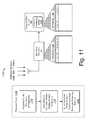
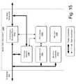
- FIG. 15is a block diagram of an exemplary smart disconnect of the power aggregation system.
- FIG. 16is a flow diagram of an exemplary method of power aggregation.
- FIG. 17is a flow diagram of an exemplary method of communicatively controlling an electric resource for power aggregation.
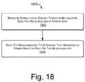
- FIG. 18is a flow diagram of an exemplary method of metering bidirectional power of an electric resource.
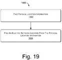
- FIG. 19is a flow diagram of an exemplary method of determining an electric network location of an electric resource.
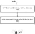
- FIG. 20is a flow diagram of an exemplary method of scheduling power aggregation.
- FIG. 21is a flow diagram of an exemplary method of smart islanding.
- FIG. 22is a flow diagram of an exemplary method of extending a user interface for power aggregation.
- FIG. 23is a flow diagram of an exemplary method of gaining and maintaining electric vehicle owners in a power aggregation system.
- Described hereinis a power aggregation system for distributed electric resources, and associated methods.
- the exemplary systemcommunicates over the Internet and/or some other public or private networks with numerous individual electric resources connected to a power grid (hereinafter, “grid”).
- grida power grid
- the exemplary systemcan dynamically aggregate these electric resources to provide power services to grid operators (e.g. utilities, Independent System Operators (ISO), etc).
- grid operatorse.g. utilities, Independent System Operators (ISO), etc.
- Power servicesrefers to energy delivery as well as other ancillary services including demand response, regulation, spinning reserves, non-spinning reserves, energy imbalance, and similar products.
- “Aggregation” as used hereinrefers to the ability to control power flows into and out of a set of spatially distributed electric resources with the purpose of providing a power service of larger magnitude.
- “Power grid operator” as used hereinrefers to the entity that is responsible for maintaining the operation and stability of the power grid within or across an electric control area. The power grid operator may constitute some combination of manual/human action/intervention and automated processes controlling generation signals in response to system sensors.
- a “control area operator”is one example of a power grid operator.
- Control arearefers to a contained portion of the electrical grid with defined input and output ports. The net flow of power into this area must equal (within some error tolerance) the sum of the power consumption within the area and power outflow from the area.
- Power gridas used herein means a power distribution system/network that connects producers of power with consumers of power.
- the networkmay include generators, transformers, interconnects, switching stations, and safety equipment as part of either/both the transmission system (i.e., bulk power) or the distribution system (i.e. retail power).
- the exemplary power aggregation systemis vertically scalable for use with a neighborhood, a city, a sector, a control area, or (for example) one of the eight large-scale Interconnects in the North American Electric Reliability Council (NERC).
- the exemplary systemis horizontally scalable for use in providing power services to multiple grid areas simultaneously.
- Grid conditionsmeans the need for more or less power flowing in or out of a section of the electric power grid, in a response to one of a number of conditions, for example supply changes, demand changes, contingencies and failures, ramping events, etc. These grid conditions typically manifest themselves as power quality events such as under- or over-voltage events and under- or over-frequency events.
- Power quality eventstypically refers to manifestations of power grid instability including voltage deviations and frequency deviations; additionally, power quality events as used herein also includes other disturbances in the quality of the power delivered by the power grid such as sub-cycle voltage spikes and harmonics.
- Electric resourcetypically refers to electrical entities that can be commanded to do some or all of these three things: take power (act as load), provide power (act as power generation or source), and store energy. Examples may include battery/charger/inverter systems for electric or hybrid vehicles, repositories of used-but-serviceable electric vehicle batteries, fixed energy storage, fuel cell generators, emergency generators, controllable loads, etc.
- Electric vehicleis used broadly herein to refer to pure electric and hybrid electric vehicles, such as plug-in hybrid electric vehicles (PHEVs), especially vehicles that have significant storage battery capacity and that connect to the power grid for recharging the battery. More specifically, electric vehicle means a vehicle that gets some or all of its energy for motion and other purposes from the power grid. Moreover, an electric vehicle has an energy storage system, which may consist of batteries, capacitors, etc., or some combination thereof. An electric vehicle may or may not have the capability to provide power back to the electric grid.
- PHEVsplug-in hybrid electric vehicles
- Electric vehicle “energy storage systems”(batteries, supercapacitors, and/or other energy storage devices) are used herein as a representative example of electric resources intermittently or permanently connected to the grid that can have dynamic input and output of power. Such batteries can function as a power source or a power load.
- a collection of aggregated electric vehicle batteriescan become a statistically stable resource across numerous batteries, despite recognizable tidal connection trends (e.g., an increase in the total umber of vehicles connected to the grid at night; a downswing in the collective number of connected batteries as the morning commute begins, etc.)
- connection trendsare predictable and such batteries become a stable and reliable resource to call upon, should the grid or a part of the grid (such as a person's home in a blackout) experience a need for increased or decreased power.
- Data collection and storagealso enable the power aggregation system to predict connection behavior on a per-user basis.
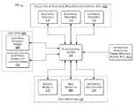
- FIG. 1shows an exemplary power aggregation system 100 .
- a flow control center 102is communicatively coupled with a network, such as a public/private mix that includes the Internet 104 , and includes one or more servers 106 providing a centralized power aggregation service.
- Internet 104will be used herein as representative of many different types of communicative networks and network mixtures.
- the flow control center 102maintains communication 108 with operators of power grid(s), and communication 110 with remote resources, i.e., communication with peripheral electric resources 112 (“end” or “terminal” nodes/devices of a power network) that are connected to the power grid 114 .
- PLCspowerline communicators
- Ethernet-over-powerline bridges 120are implemented at connection locations so that the “last mile” (in this case, last feet—e.g., in a residence 124 ) of Internet communication with remote resources is implemented over the same wire that connects each electric resource 112 to the power grid 114 .
- each physical location of each electric resource 112may be associated with a corresponding Ethernet-over-powerline bridge 120 (hereinafter, “bridge”) at or near the same location as the electric resource 112 .
- bridge 120is typically connected to an Internet access point of a location owner, as will be described in greater detail below.
- the communication medium from flow control center 102 to the connection location, such as residence 124can take many forms, such as cable modem, DSL, satellite, fiber, WiMax, etc.
- electric resources 112may connect with the Internet by a different medium than the same power wire that connects them to the power grid 114 .
- a given electric resource 112may have its own wireless capability to connect directly with the Internet 104 and thereby with the flow control center 102 .
- Electric resources 112 of the exemplary power aggregation system 100may include the batteries of electric vehicles connected to the power grid 114 at residences 124 , parking lots 126 etc.; batteries in a repository 128 , fuel cell generators, private dams, conventional power plants, and other resources that produce electricity and/or store electricity physically or electrically.
- each participating electric resource 112 or group of local resourceshas a corresponding remote intelligent power flow (IPF) module 134 (hereinafter, “remote IPF module” 134 ).
- the centralized flow control center 102administers the power aggregation system 100 by communicating with the remote IPF modules 134 distributed peripherally among the electric resources 112 .
- the remote IPF modules 134perform several different functions, including providing the flow control center 102 with the statuses of remote resources; controlling the amount, direction, and timing of power being transferred into or out of a remote electric resource 112 ; provide metering of power being transferred into or out of a remote electric resource 112 ; providing safety measures during power transfer and changes of conditions in the power grid 114 ; logging activities; and providing self-contained control of power transfer and safety measures when communication with the flow control center 102 is interrupted.
- the remote IPF modules 134will be described in greater detail below.
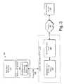
- FIG. 2shows another view of exemplary electrical and communicative connections to an electric resource 112 .
- an electric vehicle 200includes a battery bank 202 and an exemplary remote IPF module 134 .
- the electric vehicle 200may connect to a conventional wall receptacle (wall outlet) 204 of a residence 124 , the wall receptacle 204 representing the peripheral edge of the power grid 114 connected via a residential powerline 206 .
- the power cord 208 between the electric vehicle 200 and the wall outlet 204can be composed of only conventional wire and insulation for conducting alternating current (AC) power to and from the electric vehicle 200 .
- a location-specific connection locality module 210performs the function of network access point—in this case, the Internet access point.
- a bridge 120intervenes between the receptacle 204 and the network access point so that the power cord 208 can also carry network communications between the electric vehicle 200 and the receptacle 204 .
- connection locality module 210With such a bridge 120 and connection locality module 210 in place in a connection location, no other special wiring or physical medium is needed to communicate with the remote IPF module 134 of the electric vehicle 200 other than a conventional power cord 208 for providing residential line current at conventional voltage. Upstream of the connection locality module 210 , power and communication with the electric vehicle 200 are resolved into the powerline 206 and an Internet cable 104 .
- the power cord 208may include safety features not found in conventional power and extension cords.
- an electrical plug 212 of the power cord 208may include electrical and/or mechanical safeguard components to prevent the remote IPF module 134 from electrifying or exposing the male conductors of the power cord 208 when the conductors are exposed to a human user.
- FIG. 3shows another implementation of the connection locality module 210 of FIG. 2 , in greater detail.
- an electric resource 112has an associated remote IPF module 134 , including a bridge 120 .
- the power cord 208connects the electric resource 112 to the power grid 114 and also to the connection locality module 210 in order to communicate with the flow control server 106 .
- the connection locality module 210includes another instance of a bridge 120 ′, connected to a network access point 302 , which may include such components as a router, switch, and/or modem, to establish a hardwired or wireless connection with, in this case, the Internet 104 .
- the power cord 208 between the two bridges 120 and 120 ′is replaced by a wireless Internet link, such as a wireless transceiver in the remote IPF module 134 and a wireless router in the connection locality module 210 .
- FIG. 4shows an exemplary layout 400 of the power aggregation system 100 .
- the flow control center 102can be connected to many different entities, e.g., via the Internet 104 , for communicating and receiving information.
- the exemplary layout 400includes electric resources 112 , such as plug-in electric vehicles 200 , physically connected to the grid within a single control area 402 .
- the electric resources 112become an energy resource for grid operators 404 to utilize.
- the exemplary layout 400also includes end users 406 classified into electric resource owners 408 and electrical connection location owners 410 , who may or may not be one and the same.
- the stakeholders in an exemplary power aggregation system 100include the system operator at the flow control center 102 , the grid operator 404 , the resource owner 408 , and the owner of the location 410 at which the electric resource 112 is connected to the power grid 114 .
- Electrical connection location owners 410can include:
- the flow control center 102may also be coupled with information sources 414 for input of weather reports, events, price feeds, etc.
- Other data sources 414include the system stakeholders, public databases, and historical system data, which may be used to optimize system performance and to satisfy constraints on the exemplary power aggregation system 100 .
- an exemplary power aggregation system 100may consist of components that:
- These componentscan be running on a single computing resource (computer, etc.), or on a distributed set of resources (either physically co-located or not).
- Exemplary IPF systems 100 in such a layout 400can provide many benefits: for example, lower-cost ancillary services (i.e., power services), fine-grained (both temporally and spatially) control over resource scheduling, guaranteed reliability and service levels, increased service levels via intelligent resource scheduling, firming of intermittent generation sources such as wind and solar power generation.
- ancillary servicesi.e., power services
- fine-grained control over resource schedulingi.e., guaranteed reliability and service levels
- increased service levels via intelligent resource schedulingi.e., firming of intermittent generation sources such as wind and solar power generation.
- the exemplary power aggregation system 100enables a grid operator 404 to control the aggregated electric resources 112 connected to the power grid 114 .
- An electric resource 112can act as a power source, load, or storage, and the resource 112 may exhibit combinations of these properties.
- Control of an electric resource 112is the ability to actuate power consumption, generation, or energy storage from an aggregate of these electric resources 112 .
- FIG. 5shows the role of multiple control areas 402 in the exemplary power aggregation system 100 .
- Each electric resource 112can be connected to the power aggregation system 100 within a specific electrical control area.
- a single instance of the flow control center 102can administer electric resources 112 from multiple distinct control areas 501 (e.g., control areas 502 , 504 , and 506 ). In one implementation, this functionality is achieved by logically partitioning resources within the power aggregation system 100 . For example, when the control areas 402 include an arbitrary number of control areas, control area “A” 502 , control area “B” 504 , . . .
- grid operations 116can include corresponding control area operators 508 , 510 , . . . , and 512 .
- Further division into a control hierarchy that includes control division groupings above and below the illustrated control areas 402allows the power aggregation system 100 to scale to power grids 114 of different magnitudes and/or to varying numbers of electric resources 112 connected with a power grid 114 .
- FIG. 6shows an exemplary layout 600 of an exemplary power aggregation system 100 that uses multiple centralized flow control centers 102 and 102 ′.
- Each flow control center 102 and 102 ′has its own respective end users 406 and 406 ′.
- Control areas 402 to be administered by each specific instance of a flow control center 102can be assigned dynamically.
- a first flow control center 102may administer control area A 502 and control area B 504
- a second flow control center 102 ′administers control area n 506 .
- corresponding control area operators508 , 510 , and 512
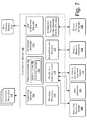
- FIG. 7shows an exemplary server 106 of the flow control center 102 .
- the illustrated implementation in FIG. 7is only one example configuration, for descriptive purposes. Many other arrangements of the illustrated components or even different components constituting an exemplary server 106 of the flow control center 102 are possible within the scope of the subject matter.
- Such an exemplary server 106 and flow control center 102can be executed in hardware, software, or combinations of hardware, software, firmware, etc.
- the exemplary flow control server 106includes a connection manager 702 to communicate with electric resources 112 , a prediction engine 704 that may include a learning engine 706 and a statistics engine 708 , a constraint optimizer 710 , and a grid interaction manager 712 to receive grid control signals 714 .
- Grid control signals 714are sometimes referred to as generation control signals, such as automated generation control (AGC) signals.
- AGCautomated generation control
- the flow control server 106may further include a database/information warehouse 716 , a web server 718 to present a user interface to electric resource owners 408 , grid operators 404 , and electrical connection location owners 410 ; a contract manager 720 to negotiate contract terms with energy markets 412 , and an information acquisition engine 414 to track weather, relevant news events, etc., and download information from public and private databases 722 for predicting behavior of large groups of the electric resources 112 , monitoring energy prices, negotiating contracts, etc.
- a database/information warehouse 716to present a user interface to electric resource owners 408 , grid operators 404 , and electrical connection location owners 410 ;
- a contract manager 720to negotiate contract terms with energy markets 412 , and an information acquisition engine 414 to track weather, relevant news events, etc., and download information from public and private databases 722 for predicting behavior of large groups of the electric resources 112 , monitoring energy prices, negotiating contracts, etc.
- the connection manager 702maintains a communications channel with each electric resource 112 that is connected to the power aggregation system 100 . That is, the connection manager 702 allows each electric resource 112 to log on and communicate, e.g., using Internet Protocol (IP) if the network is the Internet 104 . In other words, the electric resources 112 call home. That is, in one implementation they always initiate the connection with the server 106 .
- IPInternet Protocol
- the IPF module 134can connect to the home's router via the powerline connection.
- the routerwill assign the vehicle 200 an address (DHCP), and the vehicle 200 can connect to the server 106 (no holes in the firewall needed from this direction).
- DHCPvehicle address
- the IPF module 134knows to call home again and connect to the next available server resource.
- the grid interaction manager 712receives and interprets signals from the interface of the automated grid controller 118 of a grid operator 404 . In one implementation, the grid interaction manager 712 also generates signals to send to automated grid controllers 118 . The scope of the signals to be sent depends on agreements or contracts between grid operators 404 and the exemplary power aggregation system 100 . In one scenario the grid interaction manager 712 sends information about the availability of aggregate electric resources 112 to receive power from the grid 114 or supply power to the grid 114 . In another variation, a contract may allow the grid interaction manager 712 to send control signals to the automated grid controller 118 —to control the grid 114 , subject to the built-in constraints of the automated grid controller 118 and subject to the scope of control allowed by the contract.
- the database 716can store all of the data relevant to the power aggregation system 100 including electric resource logs, e.g., for electric vehicles 200 , electrical connection information, per-vehicle energy metering data, resource owner preferences, account information, etc.
- the web server 718provides a user interface to the system stakeholders, as described above.
- a user interfaceserves primarily as a mechanism for conveying information to the users, but in some cases, the user interface serves to acquire data, such as preferences, from the users.
- the web server 718can also initiate contact with participating electric resource owners 408 to advertise offers for exchanging electrical power.
- the bidding/contract manager 720interacts with the grid operators 404 and their associated energy markets 412 to determine system availability, pricing, service levels, etc.
- the information acquisition engine 414communicates with public and private databases 722 , as mentioned above, to gather data that is relevant to the operation of the power aggregation system 100 .
- the prediction engine 704may use data from the data warehouse 716 to make predictions about electric resource behavior, such as when electric resources 112 will connect and disconnect, global electric resource availability, electrical system load, real-time energy prices, etc.
- the predictionsenable the power aggregation system 100 to utilize more fully the electric resources 112 connected to the power grid 114 .
- the learning engine 706may track, record, and process actual electric resource behavior, e.g., by learning behavior of a sample or cross-section of a large population of electric resources 112 .
- the statistics engine 708may apply various probabilistic techniques to the resource behavior to note trends and make predictions.
- the prediction engine 704performs predictions via collaborative filtering.
- the prediction engine 704can also perform per-user predictions of one or more parameters, including, for example, connect-time, connect duration, state-of-charge at connect time, and connection location.
- the prediction engine 704may draw upon information, such as historical data, connect time (day of week, week of month, month of year, holidays, etc.), state-of-charge at connect, connection location, etc.
- a time series predictioncan be computed via a recurrent neural network, a dynamic Bayesian network, or other directed graphical model.
- the prediction engine 704can predict the time of the next connection, the state-of-charge at connection time, the location of the connection (and may assign it a probability/likelihood). Once the resource 112 has connected, the time-of-connection, state-of-charge at-connection, and connection location become further inputs to refinements of the predictions of the connection duration. These predictions help to guide predictions of total system availability as well as to determine a more accurate cost function for resource allocation.
- the prediction engine 704builds a reduced set of models where each model in the reduced set is used to predict the behavior of many users.
- the system 100can identify features of each user, such as number of unique connections/disconnections per day, typical connection time(s), average connection duration, average state-of-charge at connection time, etc., and can create clusters of users in either a full feature space or in some reduced feature space that is computed via a dimensionality reduction algorithm such as Principal Components Analysis, Random Projection, etc.
- the cluster assignment procedureis varied to optimize the system 100 for speed (less clusters), for accuracy (more clusters), or some combination of the two.
- This exemplary clustering techniquehas multiple benefits. First, it enables a reduced set of models, and therefore reduced model parameters, which reduces the computation time for making predictions. It also reduces the storage space of the model parameters. Second, by identifying traits (or features) of new users to the system 100 , these new users can be assigned to an existing cluster of users with similar traits, and the cluster model, built from the extensive data of the existing users, can make more accurate predictions about the new user more quickly because it is leveraging the historical performance of similar users. Of course, over time, individual users may change their behaviors and may be reassigned to new clusters that fit their behavior better.
- the constraint optimizer 710combines information from the prediction engine 704 , the data warehouse 716 , and the contract manager 720 to generate resource control signals that will satisfy the system constraints.
- the constraint optimizer 710can signal an electric vehicle 200 to charge its battery bank 202 at a certain charging rate and later to discharge the battery bank 202 for uploading power to the power grid 114 at a certain upload rate: the power transfer rates and the timing schedules of the power transfers optimized to fit the tracked individual connect and disconnect behavior of the particular electric vehicle 200 and also optimized to fit a daily power supply and demand “breathing cycle” of the power grid 114 .
- the constraint optimizer 710plays a key role in converting generation control signals 714 into vehicle control signals, mediated by the connection manager 702 . Mapping generation control signals 714 from a grid operator 404 into control signals that are sent to each unique electrical resource 112 in the system 100 is an example of a specific constraint optimization problem.
- Each resource 112has associated constraints, either hard or soft. Examples of resource constraints may include: price sensitivity of the owner, vehicle state-of-charge (e.g., if the vehicle 200 is fully charged, it cannot participate in loading the grid 114 ), predicted amount of time until the resource 112 disconnects from the system 100 , owner sensitivity to revenue versus state-of-charge, electrical limits of the resource 114 , manual charging overrides by resource owners 408 , etc.
- the constraints on a particular resource 112can be used to assign a cost for activating each of the resource's particular actions. For example, a resource whose storage system 202 has little energy stored in it will have a low cost associated with the charging operation, but a very high cost for the generation operation.
- a fully charged resource 112 that is predicted to be available for ten hourswill have a lower cost generation operation than a fully charged resource 112 that is predicted to be disconnected within the next 15 minutes, representing the negative consequence of delivering a less-than-full resource to its owner.
- the followingis one example scenario of converting one generating signal 714 that comprises a system operating level (e.g. ⁇ 10 megawatts to +10 megawatts, where + represents load, ⁇ represents generation) to a vehicle control signal.
- a system operating levele.g. ⁇ 10 megawatts to +10 megawatts, where + represents load, ⁇ represents generation
- the system 100can meter the actual power flows in each resource 112 , the actual system operating level is known at all times.
- the exemplary power aggregation system 100maintains three lists of available resources 112 .
- the first listcontains resources 112 that can be activated for charging (load) in priority order.
- Each of the resources 112 in these lists(e.g., all resources 112 can have a position in both lists) have an associated cost.
- the priority order of the listsis directly related to the cost (i.e., the lists are sorted from lowest cost to highest cost). Assigning cost values to each resource 112 is important because it enables the comparison of two operations that achieve similar results with respect to system operation. For example, adding one unit of charging (load, taking power from the grid) to the system is equivalent to removing one unit of generation.
- the third list of resources 112contains resources with hard constraints. For example, resources whose owner's 408 have overridden the system 100 to force charging will be placed on the third list of static resources.
- the grid-operator-requested operating levelchanges to +2 megawatts.
- the systemactivates charging the first ‘n’ resources from the list, where ‘n’ is the number of resources whose additive load is predicted to equal 2 megawatts. After the resources are activated, the result of the activations are monitored to determine the actual result of the action. If more than 2 megawatts of load is active, the system will disable charging in reverse priority order to maintain system operation within the error tolerance specified by the contract.
- the requested operating levelremains constant at 2 megawatts.
- the behavior of some of the electrical resourcesmay not be static.
- Other vehicles 200may connect to the system 100 and demand immediate charging. All of these actions will cause a change in the operating level of the power aggregation system 100 . Therefore, the system 100 continuously monitors the system operating level and activates or deactivates resources 112 to maintain the operating level within the error tolerance specified by the contract.
- the grid-operator-requested operating leveldecreases to ⁇ 1 megawatts.
- the systemconsults the lists of available resources and chooses the lowest cost set of resources to achieve a system operating level of ⁇ 1 megawatts. Specifically, the system moves sequentially through the priority lists, comparing the cost of enabling generation versus disabling charging, and activating the lowest cost resource at each time step. Once the operating level reaches ⁇ 1 megawatts, the system 100 continues to monitor the actual operating level, looking for deviations that would require the activation of an additional resource 112 to maintain the operating level within the error tolerance specified by the contract.
- an exemplary costing mechanismis fed information on the real-time grid generation mix to determine the marginal consequences of charging or generation (vehicle 200 to grid 114 ) on a “carbon footprint,” the impact on fossil fuel resources and the environment in general.
- the exemplary system 100also enables optimizing for any cost metric, or a weighted combination of several.
- the system 100can optimize figures of merit that may include, for example, a combination of maximizing economic value and minimizing environmental impact, etc.
- the system 100also uses cost as a temporal variable. For example, if the system 100 schedules a discharged pack to charge during an upcoming time window, the system 100 can predict its look-ahead cost profile as it charges, allowing the system 100 to further optimize, adaptively. That is, in some circumstances the system 100 knows that it will have a high-capacity generation resource by a certain future time.
- Multiple components of the flow control server 106constitute a scheduling system that has multiple functions and components:
- the scheduling functioncan enable a number of useful energy services, including:
- An exemplary power aggregation system 100aggregates and controls the load presented by many charging/uploading electric vehicles 200 to provide power services (ancillary energy services) such as regulation and spinning reserves.
- power servicesancillary energy services
- twelve operating loads of 5 kW eachcan be disabled to provide 60 kW of spinning reserves for one hour.
- the loadscan be disabled in series (three at a time) to provide 15 kW of reserves for two hours.
- more complex interleavings of individual electric resources by the power aggregation system 100are possible.
- the power aggregation system 100includes power-factor correction circuitry placed in electric vehicles 200 with the exemplary remote IPF module 134 , thus enabling such a service.
- the electric vehicles 200can have capacitors (or inductors) that can be dynamically connected to the grid, independent of whether the electric vehicle 200 is charging, delivering power, or doing nothing. This service can then be sold to utilities for distribution level dynamic VAR support.
- the power aggregation system 100can both sense the need for VAR support in a distributed manner and use the distributed remote IPF modules 134 to take actions that provide VAR support without grid operator 404 intervention.
- FIG. 8shows the remote IPF module 134 of FIGS. 1 and 2 in greater detail.
- the illustrated remote IPF module 134is only one example configuration, for descriptive purposes. Many other arrangements of the illustrated components or even different components constituting an exemplary remote IPF module 134 are possible within the scope of the subject matter.
- Such an exemplary remote IPF module 134has some hardware components and some components that can be executed in hardware, software, or combinations of hardware, software, firmware, etc.
- the illustrated example of a remote IPF module 134is represented by an implementation suited for an electric vehicle 200 .
- some vehicle systems 800are included as part of the exemplary remote IPF module 134 for the sake of description.
- the remote IPF module 134may exclude some or all of the vehicles systems 800 from being counted as components of the remote IPF module 134 .
- the depicted vehicle systems 800include a vehicle computer and data interface 802 , an energy storage system, such as a battery bank 202 , and an inverter/charger 804 .
- the remote IPF module 134also includes a communicative power flow controller 806 .
- the communicative power flow controller 806in turn includes some components that interface with AC power from the grid 114 , such as a powerline communicator, for example an Ethernet-over-powerline bridge 120 , and a current or current/voltage (power) sensor 808 , such as a current sensing transformer.
- the communicative power flow controller 806also includes Ethernet and information processing components, such as a processor 810 or microcontroller and an associated Ethernet media access control (MAC) address 812 ; volatile random access memory 814 , nonvolatile memory 816 or data storage, an interface such as an RS-232 interface 818 or a CANbus interface 820 ; an Ethernet physical layer interface 822 , which enables wiring and signaling according to Ethernet standards for the physical layer through means of network access at the MAC/Data Link Layer and a common addressing format.
- the Ethernet physical layer interface 822provides electrical, mechanical, and procedural interface to the transmission medium—i.e., in one implementation, using the Ethernet-over-powerline bridge 120 .
- wireless or other communication channels with the Internet 104are used in place of the Ethernet-over-powerline bridge 120 .
- the communicative power flow controller 806also includes a bidirectional power flow meter 824 that tracks power transfer to and from each electric resource 112 , in this case the battery bank 202 of an electric vehicle 200 .
- the communicative power flow controller 806operates either within, or connected to an electric vehicle 200 or other electric resource 112 to enable the aggregation of electric resources 112 introduced above (e.g., via a wired or wireless communication interface).
- These above-listed componentsmay vary among different implementations of the communicative power flow controller 806 , but implementations typically include:
- Implementations of the communicative power flow controller 806can enable functionality including:
- the communicative power flow controller 806includes a central processor 810 , interfaces 818 and 820 for communication within the electric vehicle 200 , a powerline communicator, such as an Ethernet-over-powerline bridge 120 for communication external to the electric vehicle 200 , and a power flow meter 824 for measuring energy flow to and from the electric vehicle 200 via a connected AC powerline 208 .
- a powerline communicatorsuch as an Ethernet-over-powerline bridge 120 for communication external to the electric vehicle 200
- a power flow meter 824for measuring energy flow to and from the electric vehicle 200 via a connected AC powerline 208 .
- the remote IPF module 134initiates a connection to the flow control server 106 , registers itself, and waits for signals from the flow control server 106 that direct the remote IPF module 134 to adjust the flow of power into or out of the electric vehicle 200 .
- These signalsare communicated to the vehicle computer 802 via the data interface, which may be any suitable interface including the RS-232 interface 818 or the CANbus interface 820 .
- the vehicle computer 802following the signals received from the flow control server 106 , controls the inverter/charger 804 to charge the vehicle's battery bank 202 or to discharge the battery bank 202 in upload to the grid 114 .
- the remote IPF module 134transmits information regarding energy flows to the flow control server 106 . If, when the electric vehicle 200 is connected to the grid 114 , there is no communications path to the flow control server 106 (i.e., the location is not equipped properly, or there is a network failure), the electric vehicle 200 can follow a preprogrammed or learned behavior of off-line operation, e.g., stored as a set of instructions in the nonvolatile memory 816 . In such a case, energy transactions can also be cached in nonvolatile memory 816 for later transmission to the flow control server 106 .
- the remote IPF module 134listens passively, logging select vehicle operation data for later analysis and consumption.
- the remote IPF module 134can transmit this data to the flow control server 106 when a communications channel becomes available.
- Poweris the rate of energy consumption per interval of time. Power indicates the quantity of energy transferred during a certain period of time, thus the units of power are quantities of energy per unit of time.
- the exemplary power flow meter 824measures power for a given electric resource 112 across a bi-directional flow—e.g., power from grid 114 to electric vehicle 200 or from electric vehicle 200 to the grid 114 .
- the remote IPF module 134can locally cache readings from the power flow meter 824 to ensure accurate transactions with the central flow control server 106 , even if the connection to the server is down temporarily, or if the server itself is unavailable.
- the exemplary power flow meter 824in conjunction with the other components of the remote IPF module 134 enables system-wide features in the exemplary power aggregation system 100 that include:
- the exemplary power aggregation system 100also includes various techniques for determining the electrical network location of a mobile electric resource 112 , such as a plug-in electric vehicle 200 .
- Electric vehicles 200can connect to the grid 114 in numerous locations and accurate control and transaction of energy exchange can be enabled by specific knowledge of the charging location.
- Some of the exemplary techniques for determining electric vehicle charging locationsinclude:
- FIG. 9shows an exemplary technique for resolving the physical location on the grid 114 of an electric resource 112 that is connected to the exemplary power aggregation system 100 .
- the remote IPF module 134obtains the Media Access Control (MAC) address 902 of the locally installed network modem or router (Internet access point) 302 .
- the remote IPF module 134then transmits this unique MAC identifier to the flow control server 106 , which uses the identifier to resolve the location of the electric vehicle 200 .
- MACMedia Access Control
- the remote IPF module 134can also sometimes use the MAC addresses or other unique identifiers of other physically installed nearby equipment that can communicate with the remote IPF module 134 , including a “smart” utility meter 904 , a cable TV box 906 , an RFID-based unit 908 , or an exemplary ID unit 910 that is able to communicate with the remote IPF module 134 .
- the ID unit 910is described in more detail in FIG. 10 .
- MAC addresses 902do not always give information about the physical location of the associated piece of hardware, but in one implementation the flow control server 106 includes a tracking database 912 that relates MAC addresses or other identifiers with an associated physical location of the hardware. In this manner, a remote IPF module 134 and the flow control server 106 can find a mobile electric resource 112 wherever it connects to the power grid 114 .
- FIG. 10shows another exemplary technique for determining a physical location of a mobile electric resource 112 on the power grid 114 .
- An exemplary ID unit 910can be plugged into the grid 114 at or near a charging location. The operation of the ID unit 910 is as follows. A newly-connected electric resource 112 searches for locally connected resources by broadcasting a ping or message in the wireless reception area. In one implementation, the ID unit 910 responds 1002 to the ping and conveys a unique identifier 1004 of the ID unit 910 back to the electric resource 112 .
- the remote IPF module 134 of the electric resource 112then transmits the unique identifier 1004 to the flow control server 106 , which determines the location of the ID unit 910 and by proxy, the exact or the approximate network location of the electric resource 112 , depending on the size of the catchment area of the ID unit 910 .
- the newly-connected electric resource 112searches for locally connected resources by broadcasting a ping or message that includes the unique identifier 1006 of the electric resource 112 .
- the ID unit 910does not need to trust or reuse the wireless connection, and does not respond back to the remote IPF module 134 of the mobile electric resource 112 , but responds 1008 directly to the flow control server 106 with a message that contains its own unique identifier 1004 and the unique identifier 1006 of the electric resource 112 that was received in the ping message.
- the central flow control server 106then associates the unique identifier 1006 of the mobile electric resource 112 with a “connected” status and uses the other unique identifier 1004 of the ID unit 910 to determine or approximate the physical location of the electric resource 112 .
- the physical locationdoes not have to be approximate, if a particular ID unit 910 is associated with only one exact network location.
- the remote IPF module 134learns that the ping is successful when it hears back from the flow control center 106 with confirmation.
- Such an exemplary ID unit 910is particularly useful in situations in which the communications path between the electric resource 112 and the flow control server 106 is via a wireless connection that does not itself enable exact determination of network location.
- FIG. 11shows another exemplary method 1100 and system 1102 for determining the location of a mobile electric resource 112 on the power grid 114 .
- the electric resource 112 and the flow control server 106conduct communications via a wireless signaling scheme, it is still desirable to determine the physical connection location during periods of connectedness with the grid 114 .
- Wireless networkscomprise many cells or towers that each transmit unique identifiers. Additionally, the strength of the connection between a tower and mobile clients connecting to the tower is a function of the client's proximity to the tower.
- the remote IPF module 134can acquire the unique identifiers of the available towers and relate these to the signal strength of each connection, as shown in database 1104 .
- the remote IPF module 134 of the electric resource 112transmits this information to the flow control server 106 , where the information is combined with survey data, such as database 1106 so that a position inference engine 1108 can triangulate or otherwise infer the physical location of the connected electric vehicle 200 .
- the IPF module 134can use the signal strength readings to resolve the resource location directly, in which case the IPF module 134 transmits the location information instead of the signal strength information.
- the exemplary method 1100includes acquiring ( 1110 ) the signal strength information; communicating ( 1112 ) the acquired signal strength information to the flow control server 106 ; and inferring ( 1114 ) the physical location using stored tower location information and the acquired signals from the electric resource 112 .
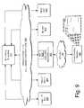
- FIG. 12shows a method 1200 and system 1202 for using signals from a global positioning satellite (GPS) system to determine a physical location of a mobile electric resource 112 on the power grid 114 .
- GPSglobal positioning satellite
- Using GPSenables a remote IPF module 134 to resolve its physical location on the power network in a non-exact manner.
- This noisy location information from GPSis transmitted to the flow control server 106 , which uses it with a survey information database 1204 to infer the location of the electric resource 112 .
- the exemplary method 1200includes acquiring ( 1206 ) the noisy position data; communicating ( 1208 ) the acquired noisy position data to the flow control server 106 ; and inferring ( 1210 ) the location using the stored survey information and the acquired data.
- the exemplary power aggregation system 100supports the following functions and interactions:
- the power aggregation system 100creates contracts outside the system and/or bids into open markets to procure contracts for power services contracts via the web server 718 and contract manager 720 .
- the system 100resolves these requests into specific power requirements upon dispatch from the grid operator 404 , and communicates these requirements to vehicle owners 408 by one of several communication techniques.
- the grid interaction manager 712accepts real-time grid control signals 714 from grid operators 404 through a power-delivery device, and responds to these signals 714 by delivering power services from connected electric vehicles 200 to the grid 114 .
- a transaction managercan report power services transactions stored in the database 716 .
- a billing managerresolves these requests into specific credit or debit billing transactions. These transactions may be communicated to a grid operator's or utility's billing system for account reconciliation. The transactions may also be used to make payments directly to resource owners 408 .
- the vehicle-resident remote IPF module 134may include a communications manager to receive offers to provide power services, display them to the user and allow the user to respond to offers. Sometimes this type of advertising or contracting interaction can be carried out by the electric resource owner 408 conventionally connecting with the web server 718 of the flow control server 106 .
- the exemplary power aggregation system 100serves as an intermediary between vehicle owners 408 (individuals, fleets, etc.) and grid operators 404 (Independent System Operators (ISOs), Regional Tranmission Operators (RTOs), utilities, etc.).
- vehicle owners 408individuals, fleets, etc.
- grid operators 404Independent System Operators (ISOs), Regional Tranmission Operators (RTOs), utilities, etc.).
- the load and storage electric resource 112 presented by a single plug-in electric vehicle 200is not a substantial enough resource for an ISO or utility to consider controlling directly. However, by aggregating many electric vehicles 200 together, managing their load behavior, and exporting a simple control interface, the power aggregation system 100 provides services that are valuable to grid operators 404 .
- the power aggregation system 100can provide incentives to owners in the form of payments, reduced charging costs, etc.
- the power aggregation system 100can also make the control of vehicle charging and uploading power to the grid 114 automatic and nearly seamless to the vehicle owner 408 , thereby making participation palatable.
- the power aggregation system 100By placing remote IPF modules 134 in electric vehicles 200 that can measure attributes of power quality, the power aggregation system 100 enables a massively distributed sensor network for the power distribution grid 114 . Attributes of power quality that the power aggregation system 100 can measure include frequency, voltage, power factor, harmonics, etc. Then, leveraging the communication infrastructure of the power aggregation system 100 , including remote IPF modules 134 , this sensed data can be reported in real time to the flow control server 106 , where information is aggregated. Also, the information can be presented to the utility, or the power aggregation system 100 can directly correct undesirable grid conditions by controlling vehicle charge/power upload behavior of numerous electric vehicles 200 , changing the load power factor, etc.
- the exemplary power aggregation system 100can also provide Uninteruptible Power Supply (UPS) or backup power for a home/business, including interconnecting islanding circuitry.
- UPSUninteruptible Power Supply
- the power aggregation system 100allows electric resources 112 to flow power out of their batteries to the home (or business) to power some or all of the home's loads.
- Certain loadsmay be configured as key loads to keep “on” during a grid power-loss event. In such a scenario, it is important to manage islanding of the residence 124 from the grid 114 .
- Such a systemmay include anti-islanding circuitry that has the ability to communicate with the electric vehicle 200 , described further below as a smart breaker box.
- the ability of the remote IPF module 134 to communicateallows the electric vehicle 200 to know if providing power is safe, “safe” being defined as “safe for utility line workers as a result of the main breaker of the home being in a disconnected state.” If grid power drops, the smart breaker box disconnects from the grid and then contacts any electric vehicles 200 or other electric resources 112 participating locally, and requests them to start providing power. When grid power returns, the smart breaker box turns off the local power sources, and then reconnects.
- the meter owner 410may give free charging.
- the vehicle owner 408may pay at the time of charging (via credit card, account, etc.)
- a pre-established accountmay be settled automatically.
- the power aggregation system 100records when electric vehicles 200 charge at locations that require payment, via vehicle IDs and location IDs, and via exemplary metering of time-annotated energy flow in/out of the vehicle. In these cases, the vehicle owner 408 is billed for energy used, and that energy is not charged to the facility's meter account owner 410 (so double-billing is avoided).
- a billing manager that performs automatic account settlingcan be integrated with the power utility, or can be implemented as a separate debit/credit system.
- An electrical charging stationwhether free or for pay, can be installed with a user interface that presents useful information to the user. Specifically, by collecting information about the grid 114 , the vehicle state, and the preferences of the user, the station can present information such as the current electricity price, the estimated recharge cost, the estimated time until recharge, the estimated payment for uploading power to the grid 114 (either total or per hour), etc.
- the information acquisition engine 414communicates with the electric vehicle 20 and with public and/or private data networks 722 to acquire the data used in calculating this information.
- the exemplary power aggregation system 100also offers other features for the benefit of electric resource owners 408 (such as vehicle owners):
- the exemplary power aggregation system 100can include methods and components for implementing safety standards and safely actuating energy discharge operations.
- the exemplary power aggregation system 100may use in-vehicle line sensors as well as smart-islanding equipment installed at particular locations.
- the power aggregation system 100enables safe vehicle-to-grid operations.
- the power aggregation system 100enables automatic coordination of resources for backup power scenarios.
- an electric vehicle 200 containing a remote IPF module 134stops vehicle-to-grid upload of power if the remote IPF module 134 senses no line power originating from the grid 114 .
- This halting of power uploadprevents electrifying a cord that may be unplugged, or electrifying a powerline 206 that is being repaired, etc.
- thisdoes not preclude using the electric vehicle 200 to provide backup power if grid power is down because the safety measures described below ensure that an island condition is not created.
- Additional smart-islanding equipment installed at a charging locationcan communicate with the remote IPF module 134 of an electric vehicle 200 to coordinate activation of power upload to the grid 114 if grid power drops.
- This technologyis a vehicle-to-home backup power capability.
- FIG. 13shows exemplary safety measures in a vehicle-to-home scenario, in which an electric resource 112 is used to provide power to a load or set of loads (as in a home).
- a breaker box 1300is connected to the utility electric meter 1302 .
- an electric resource 112is flowing power into the grid (or local loads), an islanding condition should be avoided for safety reasons.
- the electric resource 112should not energize a line that would conventionally be considered de-energized in a power outage by line workers.
- a locally installed smart grid disconnect (switch) 1304senses the utility line in order to detect a power outage condition and coordinates with the electric resource 112 to enable vehicle-to-home power transfer. In the case of a power outage, the smart grid disconnect 1304 disconnects the circuit breakers 1306 from the utility grid 114 and communicates with the electric resource 112 to begin power backup services. When the utility services return to operation, the smart grid disconnect 1304 communicates with the electric resource 112 to disable the backup services and reconnect the breakers to the utility grid 114 .
- FIG. 14shows exemplary safety measures when multiple electric resources 112 power a home.
- the smart grid disconnect 1304coordinates with all connected electric resources 112 .
- One electric resource 112is deemed the “master” 1400 for purposes of generating a reference signal 1402 and the other resources are deemed “slaves” 1404 and follow the reference of the master 1400 .
- the smart grid disconnect 1304assigns another slave 1404 to be the reference/master 1400 .
- FIG. 15shows the smart grid disconnect 1304 of FIGS. 13 and 14 , in greater detail.
- the smart grid disconnect 1304includes a processor 1502 , a communicator 1504 coupled with connected electric resources 112 , a voltages sensor 1506 capable of sensing both the internal and utility-side AC lines, a battery 1508 for operation during power outage conditions, and a battery charger 1510 for maintaining the charge level of the battery 1508 .
- a controlled breaker or relay 1512switches between grid power and electric resource-provided power when signaled by the processor 1502 .
- the exemplary power aggregation system 100can enable a number of desirable user features:
- FIG. 16shows an exemplary method 1600 of power aggregation.
- the exemplary method 1600may be performed by hardware, software, or combinations of hardware, software, firmware, etc., for example, by components of the exemplary power aggregation system 100 .
- communicationis established with each of multiple electric resources connected to a power grid.
- a central flow control servicecan manage numerous intermittent connections with mobile electric vehicles, each of which may connect to the power grid at various locations.
- An in-vehicle remote agentconnects each vehicle to the Internet when the vehicle connects to the power grid.
- the electric resourcesare individually signaled to provide power to or take power from the power grid.
- FIG. 17is a flow diagram of an exemplary method of communicatively controlling an electric resource for power aggregation.
- the exemplary method 1700may be performed by hardware, software, or combinations of hardware, software, firmware, etc., for example, by components of the exemplary intelligent power flow (IPF) module 134 .
- IPFintelligent power flow
- communicationis established between an electric resource and a service for aggregating power.
- a control signal based in part upon the informationis received from the service.
- the resourceis controlled, e.g., to provide power to the power grid or to take power from the grid, i.e., for storage.
- bidirectional power flow of the electric deviceis measured, and used as part of the information associated with the electric resource that is communicated to the service at block 1704 .
- FIG. 18is a flow diagram of an exemplary method of metering bidirectional power of an electric resource.
- the exemplary method 1800may be performed by hardware, software, or combinations of hardware, software, firmware, etc., for example, by components of the exemplary power flow meter 824 .
- energy transfer between an electric resource and a power gridis measured bidirectionally.
- the measurementsare sent to a service that aggregates power based in part on the measurements.
- FIG. 19is a flow diagram of an exemplary method of determining an electric network location of an electric resource.
- the exemplary method 1900may be performed by hardware, software, or combinations of hardware, software, firmware, etc., for example, by components of the exemplary power aggregation system 100 .
- the physical location informationis determined.
- the physical location informationmay be derived from such sources as GPS signals or from the relative strength of cell tower signals as an indicator of their location.
- the physical location informationmay derived by receiving a unique identifier associated with a nearby device, and finding the location associated with that unique identifier.
- an electric network locatione.g., of an electric resource or its connection with the power grid, is determined from the physical location information.
- FIG. 20is a flow diagram of an exemplary method of scheduling power aggregation. In the flow diagram, the operations are summarized in individual blocks.
- the exemplary method 2000may be performed by hardware, software, or combinations of hardware, software, firmware, etc., for example, by components of the exemplary flow control server 106 .
- constraints associated with individual electric resourcesare input.
- power aggregationis scheduled, based on the input constraints.
- FIG. 21is a flow diagram of an exemplary method of smart islanding. In the flow diagram, the operations are summarized in individual blocks.
- the exemplary method 2100may be performed by hardware, software, or combinations of hardware, software, firmware, etc., for example, by components of the exemplary power aggregation system 100 .
- a power outageis sensed.
- a local connectivitya network isolated from the power grid—is created.
- local energy storage resourcesare signaled to power the local connectivity.
- FIG. 22is a flow diagram of an exemplary method of extending a user interface for power aggregation.
- the exemplary method 2200may be performed by hardware, software, or combinations of hardware, software, firmware, etc., for example, by components of the exemplary power aggregation system 100 .
- a user interfaceis associated with an electric resource.
- the user interfacemay displayed in, on, or near an electric resource, such as an electric vehicle that includes an energy storage system, or the user interface may be displayed on a device associated with the owner of the electric resource, such as a cell phone or portable computer.
- power aggregation preferences and constraintsare input via the user interface.
- a usermay control a degree of participation of the electric resource in a power aggregation scenario via the user interface.
- the usermay control the characteristics of such participation.
- FIG. 23is a flow diagram of an exemplary method of gaining and maintaining electric vehicle owners in a power aggregation system.
- the exemplary method 2300may be performed by hardware, software, or combinations of hardware, software, firmware, etc., for example, by components of the exemplary power aggregation system 100 .
- electric vehicle ownersare enlisted into a power aggregation system for distributed electric resources.
- an incentiveis provided to each owner for participation in the power aggregation system.
- recurring continued service to the power aggregation systemis repeatedly compensated.
Landscapes
- Engineering & Computer Science (AREA)
- Power Engineering (AREA)
- Transportation (AREA)
- Mechanical Engineering (AREA)
- Computer Networks & Wireless Communication (AREA)
- Signal Processing (AREA)
- Business, Economics & Management (AREA)
- Development Economics (AREA)
- Strategic Management (AREA)
- Health & Medical Sciences (AREA)
- Finance (AREA)
- Marketing (AREA)
- Accounting & Taxation (AREA)
- Physics & Mathematics (AREA)
- General Business, Economics & Management (AREA)
- General Physics & Mathematics (AREA)
- Theoretical Computer Science (AREA)
- Economics (AREA)
- Computing Systems (AREA)
- General Health & Medical Sciences (AREA)
- Medical Informatics (AREA)
- Life Sciences & Earth Sciences (AREA)
- Sustainable Development (AREA)
- Sustainable Energy (AREA)
- Supply And Distribution Of Alternating Current (AREA)
- Charge And Discharge Circuits For Batteries Or The Like (AREA)
Abstract
Description
- Rental car lots—rental car companies often have a large portion of their fleet parked in the lot. They can purchase fleets of
electric vehicles 200 and, participating in apower aggregation system 100, generate revenue from idle fleet vehicles. - Public parking lots—parking lot owners can participate in the
power aggregation system 100 to generate revenue from parkedelectric vehicles 200. Vehicle owners can be offered free parking, or additional incentives, in exchange for providing power services. - Workplace parking—employers can participate in a
power aggregation system 100 to generate revenue from parked employeeelectric vehicles 200. Employees can be offered incentives in exchange for providing power services. - Residences—a home garage can merely be equipped with a
connection locality module 210 to enable the homeowner to participate in thepower aggregation system 100 and generate revenue from a parked car. Also, thevehicle battery 202 and associated power electronics within the vehicle can provide local power backup power during times of peak load or power outages. - Residential neighborhoods—neighborhoods can participate in a
power aggregation system 100 and be equipped with power-delivery devices (deployed, for example, by homeowner cooperative groups) that generate revenue from parkedelectric vehicles 200. - The
grid operations 116 ofFIG. 4 collectively include interactions withenergy markets 412, the interactions ofgrid operators 404, and the interactions ofautomated grid controllers 118 that perform automatic physical control of thepower grid 114.
- Rental car lots—rental car companies often have a large portion of their fleet parked in the lot. They can purchase fleets of
- communicate with the
electric resources 112 to gather data and actuate charging/discharging of theelectric resources 112; - gather real-time energy prices;
- gather real-time resource statistics;
- predict behavior of electric resources112 (connectedness, location, state (such as battery State-Of-Charge) at time of connect/disconnect);
- predict behavior of the
power grid 114/load; - encrypt communications for privacy and data security;
- actuate charging of
electric vehicles 200 to optimize some figure(s) of merit; - offer guidelines or guarantees about load availability for various points in the future, etc.
- communicate with the
- data collection (gathers real-time data and stores historical data);
- projections via the
prediction engine 704, which inputs real-time data, historical data, etc.; and outputs resource availability forecasts; - optimizations built on resource availability forecasts, constraints, such as command signals from
grid operators 404, user preferences, weather conditions, etc. The optimizations can take the form of resource control plans that optimize a desired metric.
- ancillary services, such as rapid response services and fast regulation;
- energy to compensate for sudden, foreseeable, or unexpected grid imbalances;
- response to routine and unstable demands;
- firming of renewable energy sources (e.g. complementing wind-generated power).
- an intra-vehicle communications mechanism that enables communication with other vehicle components;
- a mechanism to communicate with the
flow control center 102; - a processing element;
- a data storage element;
- a power meter; and
- optionally, a user interface.
- executing pre-programmed or learned behaviors when the
electric resource 112 is offline (not connected toInternet 104, or service is unavailable); - storing locally-cached behavior profiles for “roaming” connectivity (what to do when charging on a foreign system or in disconnected operation, i.e., when there is no network connectivity);
- allowing the user to override current system behavior; and
- metering power-flow information and caching meter data during offline operation for later transaction.
- executing pre-programmed or learned behaviors when the
- tracking energy usage on an electric resource-specific basis;
- power-quality monitoring (checking if voltage, frequency, etc. deviate from their nominal operating points, and if so, notifying grid operators, and potentially modifying resource power flows to help correct the problem);
- vehicle-specific billing and transactions for energy usage;
- mobile billing (support for accurate billing when the
electric resource owner 408 is not the electrical connection location owner410 (i.e., not the meter account owner). Data from thepower flow meter 824 can be captured at theelectric vehicle 200 for billing; - integration with a smart meter at the charging location (bi-directional information exchange); and
- tamper resistance (e.g., when the
power flow meter 824 is protected within anelectric resource 112 such as an electric vehicle200).
- querying a unique identifier for the location (via wired, wireless, etc.), which can be:
- the unique ID of the network hardware at the charging site;
- the unique ID of the locally installed smart meter, by communicating with the meter;
- a unique ID installed specifically for this purpose at a site; and
- using GPS or other signal sources (cell, WiMAX, etc.) to establish a “soft” (estimated geographic) location, which is then refined based on user preferences and historical data (e.g., vehicles tend to be plugged-in at the owner's
residence 124, not a neighbor's residence).
- vehicle owners can earn free electricity for vehicle charging in return for participating in the system;
- vehicle owners can experience reduced charging cost by avoiding peak time rates;
- vehicle owners can receive payments based on the actual energy service their vehicle provides;
- vehicle owners can receive a preferential tariff for participating in the system.
- the
power aggregation system 100 as electric resource aggregator can earn a management fee (which may be some function of services provided), paid by thegrid operator 404. - the
power aggregation system 100 as electric resource aggregator can sell intopower markets 412; grid operators 404 may pay for thepower aggregation system 100, but operate thepower aggregation system 100 themselves.
- the
- data collection can include distance driven and both electrical and non-electrical fuel usage, to allow derivation and analysis of overall vehicle efficiency (in terms of energy, expense, environmental impact, etc.). This data is exported to the
flow control server 106 for storage716, as well as for display on an in-vehicle user interface, charging station user interface, and web/cell phone user interface. - intelligent charging learns the vehicle behavior and adapts the charging timing automatically. The
vehicle owner 408 can override and request immediate charging if desired.
- data collection can include distance driven and both electrical and non-electrical fuel usage, to allow derivation and analysis of overall vehicle efficiency (in terms of energy, expense, environmental impact, etc.). This data is exported to the
Claims (13)
Priority Applications (6)
| Application Number | Priority Date | Filing Date | Title |
|---|---|---|---|
| US11/836,747US7747739B2 (en) | 2006-08-10 | 2007-08-09 | Connection locator in a power aggregation system for distributed electric resources |
| US12/252,803US8898278B2 (en) | 2006-08-10 | 2008-10-16 | Connection locator in a power aggregation system for distributed electric resources |
| US12/826,282US20110025556A1 (en) | 2006-08-10 | 2010-06-29 | Connection locator in a power aggregation system for distributed electric resources |
| US14/553,480US9674771B2 (en) | 2006-08-10 | 2014-11-25 | Connection locator in a power aggregation system for distributed electric resources |
| US15/488,029US20180098271A1 (en) | 2006-08-10 | 2017-04-14 | Connection locator in a power aggregation system for distributed electric resources |
| US16/059,546US10892639B2 (en) | 2006-08-10 | 2018-08-09 | Connection locator in a power aggregation system for distributed electric resources |
Applications Claiming Priority (4)
| Application Number | Priority Date | Filing Date | Title |
|---|---|---|---|
| US82204706P | 2006-08-10 | 2006-08-10 | |
| US86943906P | 2006-12-11 | 2006-12-11 | |
| US91534707P | 2007-05-01 | 2007-05-01 | |
| US11/836,747US7747739B2 (en) | 2006-08-10 | 2007-08-09 | Connection locator in a power aggregation system for distributed electric resources |
Related Child Applications (2)
| Application Number | Title | Priority Date | Filing Date |
|---|---|---|---|
| US12/252,803Continuation-In-PartUS8898278B2 (en) | 2006-08-10 | 2008-10-16 | Connection locator in a power aggregation system for distributed electric resources |
| US12/826,282ContinuationUS20110025556A1 (en) | 2006-08-10 | 2010-06-29 | Connection locator in a power aggregation system for distributed electric resources |
Publications (2)
| Publication Number | Publication Date |
|---|---|
| US20080040479A1 US20080040479A1 (en) | 2008-02-14 |
| US7747739B2true US7747739B2 (en) | 2010-06-29 |
Family
ID=39052160
Family Applications (2)
| Application Number | Title | Priority Date | Filing Date |
|---|---|---|---|
| US11/836,747Active2028-03-18US7747739B2 (en) | 2006-08-10 | 2007-08-09 | Connection locator in a power aggregation system for distributed electric resources |
| US12/826,282AbandonedUS20110025556A1 (en) | 2006-08-10 | 2010-06-29 | Connection locator in a power aggregation system for distributed electric resources |
Family Applications After (1)
| Application Number | Title | Priority Date | Filing Date |
|---|---|---|---|
| US12/826,282AbandonedUS20110025556A1 (en) | 2006-08-10 | 2010-06-29 | Connection locator in a power aggregation system for distributed electric resources |
Country Status (1)
| Country | Link |
|---|---|
| US (2) | US7747739B2 (en) |
Cited By (122)
| Publication number | Priority date | Publication date | Assignee | Title |
|---|---|---|---|---|
| US20090030712A1 (en)* | 2007-07-26 | 2009-01-29 | Bradley D. Bogolea | System and method for transferring electrical power between grid and vehicle |
| US20090177580A1 (en)* | 2008-01-07 | 2009-07-09 | Lowenthal Richard W | Collection of electric vehicle power consumption tax |
| US20090281679A1 (en)* | 2008-05-09 | 2009-11-12 | Taft Jeffrey D | Intelligent monitoring of an electrical utility grid |
| US20090326726A1 (en)* | 2008-06-25 | 2009-12-31 | Versify Solutions, Llc | Aggregator, monitor, and manager of distributed demand response |
| US20100082464A1 (en)* | 2008-10-01 | 2010-04-01 | Keefe Robert A | System and Method for Managing the Consumption and Discharging of Power of Electric Vehicles |
| US20100082277A1 (en)* | 2008-09-30 | 2010-04-01 | Ballard Claudio R | Distributed car charging management system and method |
| US20100164287A1 (en)* | 2008-12-25 | 2010-07-01 | Honda Motor Co., Ltd. | Electric power supply system between vehicle and house |
| US20100211643A1 (en)* | 2009-02-17 | 2010-08-19 | Richard Lowenthal | Transmitting Notification Messages for an Electric Vehicle Charging Network |
| US20100244775A1 (en)* | 2009-03-25 | 2010-09-30 | Smith Lynn B | Bidirectional energy converter |
| US20100256846A1 (en)* | 2009-04-07 | 2010-10-07 | Cisco Technology, Inc. | System and method for managing electric vehicle travel |
| US20100253142A1 (en)* | 2009-04-07 | 2010-10-07 | Caterpillar Inc. | System and Method for Supplying Power to a Power Grid |
| CN101958567A (en)* | 2010-10-25 | 2011-01-26 | 东南大学 | Electric vehicle charging station system with energy storage device and control method thereof |
| US20110106321A1 (en)* | 2009-11-03 | 2011-05-05 | Spirae, Inc. | Dynamic distributed power grid control system |
| US20110118894A1 (en)* | 2009-06-29 | 2011-05-19 | Powergetics, Inc. | High speed feedback adjustment of power charge/discharge from energy storage system |
| US20110121791A1 (en)* | 2009-11-23 | 2011-05-26 | International Business Machines Corporation | Charging management method and system |
| US20110196692A1 (en)* | 2010-02-09 | 2011-08-11 | Chavez Jr Lloyd G | Apparatus, system and method for grid storage |
| US20120023225A1 (en)* | 2009-07-20 | 2012-01-26 | Imes Kevin R | Energy management system and method |
| US20120105011A1 (en)* | 2010-11-01 | 2012-05-03 | Jongsoo Park | Power control apparatus and power control method |
| US20120106672A1 (en)* | 2010-10-27 | 2012-05-03 | The Aes Corporation | Methods and adapters for use with electric devices to manage energy services |
| US20120123670A1 (en)* | 2010-11-16 | 2012-05-17 | Honda Motor Co., Ltd. | System and method for updating charge station information |
| US8254734B2 (en) | 2008-03-07 | 2012-08-28 | Veedims, Llc | Virtual electronic switch system |
| US20120228928A1 (en)* | 2011-03-11 | 2012-09-13 | Denso Corporation | Vehicular electric power supply device and electric power supply system |
| US8303337B2 (en) | 2007-06-06 | 2012-11-06 | Veedims, Llc | Hybrid cable for conveying data and power |
| US8306671B1 (en) | 2012-01-19 | 2012-11-06 | General Compression, Inc. | System and method for conserving energy resources through storage and delivery of renewable energy |
| US20120292997A1 (en)* | 2011-05-16 | 2012-11-22 | Chulwoo Lee | Network system and control method thereof |
| US20120316688A1 (en)* | 2011-06-08 | 2012-12-13 | Alstom Grid | Coordinating energy management systems and intelligent electrical distribution grid control systems |
| US20120326514A1 (en)* | 2011-06-21 | 2012-12-27 | Samsung Electronics Co., Ltd. | Power supply control apparatus and power supply control system having the same |
| US8421592B1 (en)* | 2008-10-15 | 2013-04-16 | Sprint Communications Company L.P. | Mediation of electric vehicle charging by wireless network provider |
| US8432131B2 (en) | 2008-01-07 | 2013-04-30 | Chargepoint, Inc. | Network-controlled charging system for electric vehicles |
| US20130116845A1 (en)* | 2010-05-19 | 2013-05-09 | Florian Krug | Method for controlling the stability of an electric supply grid |
| US8526311B2 (en) | 2007-06-06 | 2013-09-03 | Veedims, Llc | System for integrating a plurality of modules using a power/data backbone network |
| US8589076B2 (en) | 2011-09-14 | 2013-11-19 | International Business Machines Corporation | Power usage planning for a vehicle |
| US8595122B2 (en) | 2010-07-23 | 2013-11-26 | Electric Transportation Engineering Corporation | System for measuring electricity and method of providing and using the same |
| US8606686B1 (en) | 2008-03-07 | 2013-12-10 | Versify Solutions, Inc. | System and method for gathering and performing complex analyses on power data from multiple remote sources |
| US20140046499A1 (en)* | 2012-08-08 | 2014-02-13 | Cognizant Technology Solutions India Pvt. Ltd. | Method and system for managing and controlling electrical vehicle charging events |
| US20140058577A1 (en)* | 2012-08-27 | 2014-02-27 | Stem, Inc. | Method and apparatus for balancing power on a per phase basis in multi-phase electrical load facilities using an energy storage system |
| US20140070617A1 (en)* | 2012-09-13 | 2014-03-13 | Stem, Inc | Method and apparatus for stabalizing power on an electrical grid using networked distributed energy storage systems |
| US20140074311A1 (en)* | 2012-09-13 | 2014-03-13 | Stem, Inc | Method and apparatus for damping power oscillations on an electrical grid using networked distributed energy storage systems |
| US8686687B2 (en) | 2008-12-15 | 2014-04-01 | Comverge, Inc. | Method and system for co-operative charging of electric vehicles |
| US8710372B2 (en) | 2010-07-23 | 2014-04-29 | Blink Acquisition, LLC | Device to facilitate moving an electrical cable of an electric vehicle charging station and method of providing the same |
| US8725330B2 (en) | 2010-06-02 | 2014-05-13 | Bryan Marc Failing | Increasing vehicle security |
| US8761948B1 (en) | 2008-04-25 | 2014-06-24 | Versify Solutions, Inc. | System and method for managing and monitoring renewable energy power generation |
| US8774977B2 (en) | 2011-12-29 | 2014-07-08 | Stem, Inc. | Multiphase electrical power construction and assignment at minimal loss |
| US8803570B2 (en) | 2011-12-29 | 2014-08-12 | Stem, Inc | Multiphase electrical power assignment at minimal loss |
| US8866436B2 (en) | 2008-01-07 | 2014-10-21 | Chargepoint, Inc. | Street light mounted network-controlled charge transfer device for electric vehicles |
| US20140327404A1 (en)* | 2011-11-10 | 2014-11-06 | Evonik Industries Ag | Method for providing control power by an energy store by using tolerances in the determination of the frequency deviation |
| US8922192B2 (en) | 2011-12-30 | 2014-12-30 | Stem, Inc. | Multiphase electrical power phase identification |
| US8924033B2 (en) | 2010-05-12 | 2014-12-30 | Alstom Grid Inc. | Generalized grid security framework |
| US8930034B1 (en)* | 2007-03-21 | 2015-01-06 | Sandia Corporation | Computing an operating parameter of a unified power flow controller |
| US8965590B2 (en) | 2011-06-08 | 2015-02-24 | Alstom Grid Inc. | Intelligent electrical distribution grid control system data |
| US8965719B1 (en) | 2008-03-07 | 2015-02-24 | Versify Solutions, Inc. | Universal performance monitor for power generators |
| US8976541B2 (en) | 2011-08-31 | 2015-03-10 | Potens Ip Holdings Llc | Electrical power and data distribution apparatus |
| US20150081122A1 (en)* | 2013-09-13 | 2015-03-19 | Nissan North America, Inc. | Methods of decreasing peak energy consumption |
| US20150162784A1 (en)* | 2012-12-12 | 2015-06-11 | Paul Harriman Kydd | Vehicle-Solar-Grid Integration |
| EP2774010A4 (en)* | 2011-10-31 | 2015-07-08 | Abb Research Ltd | SYSTEMS AND METHODS FOR RESTORING SERVICE IN ELECTRICAL SYSTEMS |
| US9166408B2 (en) | 2011-05-16 | 2015-10-20 | General Electric Company | Demand response management system and method with VAR support |
| US9171256B2 (en) | 2010-12-17 | 2015-10-27 | ABA Research Ltd. | Systems and methods for predicting customer compliance with demand response requests |
| US20150306970A1 (en)* | 2012-07-18 | 2015-10-29 | Electronics And Telecommunications Research Institute | Energy management method and energy management system using same |
| WO2015179960A1 (en)* | 2014-05-30 | 2015-12-03 | Zolair Energy Ltd. | Power provision via cell phone network |
| US9209652B2 (en) | 2009-08-21 | 2015-12-08 | Allure Energy, Inc. | Mobile device with scalable map interface for zone based energy management |
| US9250660B2 (en) | 2012-11-14 | 2016-02-02 | Laserlock Technologies, Inc. | “HOME” button with integrated user biometric sensing and verification system for mobile device |
| US9281689B2 (en) | 2011-06-08 | 2016-03-08 | General Electric Technology Gmbh | Load phase balancing at multiple tiers of a multi-tier hierarchical intelligent power distribution grid |
| US9348381B2 (en) | 2011-10-19 | 2016-05-24 | Zeco Systems Pte Ltd | Methods and apparatuses for charging of electric vehicles |
| US9360874B2 (en) | 2009-08-21 | 2016-06-07 | Allure Energy, Inc. | Energy management system and method |
| US9379559B2 (en) | 2012-02-03 | 2016-06-28 | International Business Machines Corporation | System and method of charging a vehicle using a dynamic power grid, and system and method of managing power consumption in the vehicle |
| US9406094B2 (en) | 2012-08-14 | 2016-08-02 | Stem Inc. | Method and apparatus for delivering power using external data |
| US20160308356A1 (en)* | 2015-04-16 | 2016-10-20 | Abb Technology Ag | Method and Apparatus for Electrical Distribution Grid Control |
| US9485236B2 (en) | 2012-11-14 | 2016-11-01 | Verifyme, Inc. | System and method for verified social network profile |
| US9577435B2 (en) | 2013-03-13 | 2017-02-21 | Abb Research Ltd. | Method and apparatus for managing demand response resources in a power distribution network |
| US9600790B2 (en) | 2010-10-29 | 2017-03-21 | Salman Mohagheghi | Dispatching mobile energy resources to respond to electric power grid conditions |
| US9630511B2 (en) | 2014-03-05 | 2017-04-25 | Nissan North America, Inc. | Vehicle-to-grid system with power loss compensation |
| US9634508B2 (en) | 2012-09-13 | 2017-04-25 | Stem, Inc. | Method for balancing frequency instability on an electric grid using networked distributed energy storage systems |
| US9641026B2 (en) | 2011-06-08 | 2017-05-02 | Alstom Technology Ltd. | Enhanced communication infrastructure for hierarchical intelligent power distribution grid |
| US9716530B2 (en) | 2013-01-07 | 2017-07-25 | Samsung Electronics Co., Ltd. | Home automation using near field communication |
| US9731615B2 (en) | 2015-03-24 | 2017-08-15 | Honda Motor Co., Ltd. | Grid overlay for a zip coded map system and method therefor |
| US9800463B2 (en) | 2009-08-21 | 2017-10-24 | Samsung Electronics Co., Ltd. | Mobile energy management system |
| US9966762B2 (en) | 2011-11-10 | 2018-05-08 | Evonik Degussa Gmbh | Method for providing control power by an energy store by using tolerances in the delivery of power |
| US9987940B2 (en) | 2014-09-16 | 2018-06-05 | Honda Motor Co., Ltd. | Priority based vehicle control strategy |
| US20180194238A1 (en)* | 2017-01-10 | 2018-07-12 | Toyota Jidosha Kabushiki Kaisha | Charge controller and charge control method |
| US10063499B2 (en) | 2013-03-07 | 2018-08-28 | Samsung Electronics Co., Ltd. | Non-cloud based communication platform for an environment control system |
| US10129383B2 (en) | 2014-01-06 | 2018-11-13 | Samsung Electronics Co., Ltd. | Home management system and method |
| US10135628B2 (en) | 2014-01-06 | 2018-11-20 | Samsung Electronics Co., Ltd. | System, device, and apparatus for coordinating environments using network devices and remote sensory information |
| US10250520B2 (en) | 2011-08-30 | 2019-04-02 | Samsung Electronics Co., Ltd. | Customer engagement platform and portal having multi-media capabilities |
| US10284003B2 (en) | 2012-10-09 | 2019-05-07 | General Electric Company | End-user based backup management |
| US10298013B2 (en) | 2011-09-30 | 2019-05-21 | Abb Research Ltd. | Systems and methods for integrating demand response with service restoration in an electric distribution system |
| US10442302B2 (en) | 2009-05-14 | 2019-10-15 | Battelle Memorial Institute | Battery charging control methods, electrical vehicle charging methods, battery charging control apparatus, and electrical vehicles |
| US10634111B2 (en) | 2016-12-12 | 2020-04-28 | Kohler Co. | Ignition module for internal combustion engine with integrated communication device |
| US10693294B2 (en) | 2012-09-26 | 2020-06-23 | Stem, Inc. | System for optimizing the charging of electric vehicles using networked distributed energy storage systems |
| US10752128B1 (en)* | 2019-06-27 | 2020-08-25 | Bayerische Motoren Werke Aktiengesellschaft | Systems and method for EV battery second-life management |
| US11035682B2 (en) | 2016-09-15 | 2021-06-15 | Simpsx Technologies Llc | Navigation routes as community object virtual hub sequences to which users may subscribe |
| US11081897B2 (en) | 2009-06-29 | 2021-08-03 | Stem, Inc. | High speed feedback adjustment of power charge/discharge from an energy storage system |
| US11127056B2 (en) | 2017-11-30 | 2021-09-21 | Honda Motor Co., Ltd. | System and method for determining at least one demand response overhead percentage |
| US11135936B2 (en) | 2019-03-06 | 2021-10-05 | Fermata, LLC | Methods for using temperature data to protect electric vehicle battery health during use of bidirectional charger |
| US11138661B2 (en) | 2016-09-15 | 2021-10-05 | Simpsx Technologies Llc | Agriculture community objects with price-time priority queues for transformed agriculture units |
| US11138827B2 (en) | 2016-09-15 | 2021-10-05 | Simpsx Technologies Llc | Implementations of a computerized business transaction exchange for various users |
| US11157852B2 (en) | 2016-09-15 | 2021-10-26 | Simpsx Technologies Llc | Tool appliance community objects with price-time priority queues for transformed tool appliance units |
| US11215466B2 (en) | 2016-09-15 | 2022-01-04 | Circlesx Llc | Route community objects with price-time priority queues for transformed transportation units |
| US11454999B2 (en) | 2012-08-29 | 2022-09-27 | Stem, Inc. | Method and apparatus for automatically reconfiguring multi-phased networked energy storage devices at a site |
| US11500526B2 (en) | 2017-01-13 | 2022-11-15 | Circlesx Llc | Computer ball device for mixed reality, virtual reality, or augmented reality |
| WO2022260504A1 (en)* | 2021-06-08 | 2022-12-15 | Université Internationale de RABAT | Multiport aggregator for one-way and two-way dc and ac charging stations |
| US11740777B2 (en) | 2016-09-15 | 2023-08-29 | Circlesx Llc | Multi-dimension information service helmet method and system |
| US11790382B2 (en) | 2016-09-15 | 2023-10-17 | Circlesx Llc | Method to transmit geolocation exchange based markets |
| US11810023B2 (en) | 2018-10-22 | 2023-11-07 | Circlesx Llc | System and method for a transportation or freight capacity exchange for one or more transportation or freight capacity units |
| US11823090B2 (en) | 2016-09-15 | 2023-11-21 | Circlesx Llc | Transportation and freight and parking and tolling and curb capacity unit IPO method and system |
| US11836791B2 (en) | 2016-09-15 | 2023-12-05 | Circlesx Llc | Securitization of transportation units |
| US11861527B2 (en) | 2018-11-07 | 2024-01-02 | Circlesx Llc | Financial swap payment structure method and system on transportation capacity unit assets |
| US11880883B2 (en) | 2016-09-15 | 2024-01-23 | Circlesx Llc | Systems and methods for geolocation portfolio exchanges |
| US11907870B2 (en) | 2018-01-23 | 2024-02-20 | Circlesx Llc | Market exchange for transportation capacity in transportation vehicles |
| US11958372B2 (en) | 2019-11-26 | 2024-04-16 | Fermata Energy Llc | Device for bi-directional power conversion and charging for use with electric vehicles |
| US12001999B2 (en) | 2016-09-15 | 2024-06-04 | Circlesx Llc | Price based navigation |
| US12039585B2 (en) | 2017-04-10 | 2024-07-16 | Circlesx Llc | System and method for blood and saliva optimized food consumption and delivery |
| US12038726B2 (en) | 2021-08-13 | 2024-07-16 | Honda Motor Co., Ltd. | Methods and systems for managing vehicle-grid integration |
| US12106365B2 (en) | 2016-09-15 | 2024-10-01 | Circlesx Llc | Web browser and operating system portal and search portal with price time priority queues |
| US12141885B2 (en) | 2016-09-15 | 2024-11-12 | Circlesx Llc | Parking community objects with price-time priority queues for transformed parking units |
| US12152894B2 (en) | 2016-09-15 | 2024-11-26 | Circlesx Llc | Multi-dimension classification object matrices to estimate multi-dimensional representations with multi function device |
| US12154183B2 (en) | 2016-09-15 | 2024-11-26 | Circlesx Llc | System and method for a tutoring exchange for tutoring units |
| US12165223B2 (en) | 2016-09-15 | 2024-12-10 | Circlesx Llc | Renewable energy community objects with price-time priority queues for transformed renewable energy units |
| US12260456B2 (en) | 2016-09-15 | 2025-03-25 | Circlesx Llc | Virtual reality, augmented reality, mixed reality data exchange social network with multi dimensional map tile porting |
| US12320654B2 (en) | 2018-01-23 | 2025-06-03 | Circlesx Llc | Financial swap index method and system on transportation capacity units and trading derivative products based thereon |
| US12346987B2 (en) | 2016-09-15 | 2025-07-01 | Circlesx Llc | Price time priority queue routing for transportation capacity units |
| US12354033B2 (en) | 2016-09-15 | 2025-07-08 | Circlesx Llc | Time interval geolocation community objects with price-time priority queues for transformed time interval geolocation units |
| US12361486B2 (en) | 2016-09-15 | 2025-07-15 | Circlesx Llc | Toll and congestion community objects with price-time priority queues for transformed toll and congestion capacity units |
Families Citing this family (116)
| Publication number | Priority date | Publication date | Assignee | Title |
|---|---|---|---|---|
| US8213895B2 (en)* | 2005-10-03 | 2012-07-03 | Broadcom Europe Limited | Multi-wideband communications over multiple mediums within a network |
| US20080039979A1 (en)* | 2006-08-10 | 2008-02-14 | V2 Green Inc. | Smart Islanding and Power Backup in a Power Aggregation System for Distributed Electric Resources |
| WO2009006937A1 (en)* | 2007-07-09 | 2009-01-15 | Abb Research Ltd | Data recording apparatus |
| US8890505B2 (en) | 2007-08-28 | 2014-11-18 | Causam Energy, Inc. | System and method for estimating and providing dispatchable operating reserve energy capacity through use of active load management |
| US8805552B2 (en) | 2007-08-28 | 2014-08-12 | Causam Energy, Inc. | Method and apparatus for actively managing consumption of electric power over an electric power grid |
| US9130402B2 (en) | 2007-08-28 | 2015-09-08 | Causam Energy, Inc. | System and method for generating and providing dispatchable operating reserve energy capacity through use of active load management |
| US12438368B2 (en) | 2007-08-28 | 2025-10-07 | Causam Enterprises, Inc. | System and method for estimating and providing dispatchable operating reserve energy capacity through use of active load management |
| US8806239B2 (en) | 2007-08-28 | 2014-08-12 | Causam Energy, Inc. | System, method, and apparatus for actively managing consumption of electric power supplied by one or more electric power grid operators |
| US9177323B2 (en) | 2007-08-28 | 2015-11-03 | Causam Energy, Inc. | Systems and methods for determining and utilizing customer energy profiles for load control for individual structures, devices, and aggregation of same |
| US10295969B2 (en) | 2007-08-28 | 2019-05-21 | Causam Energy, Inc. | System and method for generating and providing dispatchable operating reserve energy capacity through use of active load management |
| US7693609B2 (en)* | 2007-09-05 | 2010-04-06 | Consolidated Edison Company Of New York, Inc. | Hybrid vehicle recharging system and method of operation |
| US20090187579A1 (en)* | 2008-01-20 | 2009-07-23 | Brancaccio Daniel S | System, Method and Product for Processing Utility Data |
| US8200372B2 (en)* | 2008-03-31 | 2012-06-12 | The Royal Institution For The Advancement Of Learning/Mcgill University | Methods and processes for managing distributed resources in electricity power generation and distribution networks |
| US20090259603A1 (en)* | 2008-04-10 | 2009-10-15 | Juice Technologies, Inc. | Mobile intelligent metering and charging system for charging uniquely identifiable chargeable vehicle destinations and method for employing same |
| US8736225B2 (en)* | 2008-08-20 | 2014-05-27 | San Diego Gas & Electronic Company | Modularized interface and related method for connecting plug-in electric vehicles to the energy grid |
| ATE501417T1 (en)* | 2008-11-27 | 2011-03-15 | Ubitricity Ges Fuer Verteilte Energiesysteme Mbh | COUNTING AND MEASURING POINT SYSTEM FOR MEASURING AND COUNTING ELECTRICAL ENERGY AND METHOD |
| US20100145885A1 (en)* | 2008-12-05 | 2010-06-10 | Lava Four, Llc | System for on-board metering of recharging energy consumption in vehicles equipped with electrically powered propulsion systems |
| US20100156349A1 (en)* | 2008-12-22 | 2010-06-24 | Nathan Bowman Littrell | System and method for pay as you go charging for electric vehicles |
| US8315930B2 (en)* | 2008-12-22 | 2012-11-20 | General Electric Company | Systems and methods for charging an electric vehicle using broadband over powerlines |
| US20100161517A1 (en)* | 2008-12-22 | 2010-06-24 | Nathan Bowman Littrell | Systems and methods for electricity metering for vehicular applications |
| US20100161393A1 (en)* | 2008-12-22 | 2010-06-24 | Nathan Bowman Littrell | Systems and methods for charging an electric vehicle within a parking area |
| US9396462B2 (en) | 2008-12-22 | 2016-07-19 | General Electric Company | System and method for roaming billing for electric vehicles |
| US9030153B2 (en) | 2008-12-22 | 2015-05-12 | General Electric Company | Systems and methods for delivering energy to an electric vehicle with parking fee collection |
| US8583551B2 (en) | 2008-12-22 | 2013-11-12 | General Electric Company | Systems and methods for prepaid electric metering for vehicles |
| US9505317B2 (en) | 2008-12-22 | 2016-11-29 | General Electric Company | System and method for electric vehicle charging and billing using a wireless vehicle communication service |
| CN102449572A (en)* | 2009-03-31 | 2012-05-09 | 栅点股份有限公司 | Electric vehicle power management systems |
| ITMI20090711A1 (en)* | 2009-04-27 | 2010-10-28 | Sandra Magnani | EQUIPMENT FOR THE MANAGEMENT OF ELECTRIC ENERGY PURCHASED / PRODUCED BY A USER / MANUFACTURER |
| US8359126B2 (en)* | 2009-04-30 | 2013-01-22 | GM Global Technology Operations LLC | Method to resolve a remote electrical outlet for an electrically-powered vehicle |
| US20100280675A1 (en)* | 2009-04-30 | 2010-11-04 | Gm Global Technology Operations, Inc. | Method for managing electric vehicle charging loads on a local electric power infrastructure |
| JP2011101534A (en)* | 2009-11-06 | 2011-05-19 | Panasonic Electric Works Co Ltd | Electric power interchange system |
| JP2013513353A (en)* | 2009-12-03 | 2013-04-18 | エー123 システムズ, インコーポレイテッド | Grid load synchronization device and method |
| US20110196711A1 (en)* | 2010-02-05 | 2011-08-11 | Panasonic Automotive Systems Company Of America, Division Of Panasonic Corporation Of North America | Content personalization system and method |
| US9114721B2 (en)* | 2010-05-25 | 2015-08-25 | Mitsubishi Electric Corporation | Electric power information management apparatus, electric power information management system, and electric power information management method |
| ES2788710T3 (en)* | 2010-07-06 | 2020-10-22 | Abb Schweiz Ag | Electric vehicle charging |
| WO2012005553A2 (en)* | 2010-07-09 | 2012-01-12 | (주)브이이엔에스 | Electric vehicle, charging stand, and method for charging the electric vehicle |
| US20120016546A1 (en)* | 2010-07-14 | 2012-01-19 | Nilssen Ole K | System and Method for Supplying Back-Up Electric Power to a House from a Hybrid Vehicle |
| US9340117B2 (en)* | 2010-08-05 | 2016-05-17 | Mitsubishi Jidosha Kogyo Kabushiki Kaisha | Power supply and demand leveling system |
| US8639409B2 (en)* | 2010-09-30 | 2014-01-28 | Hitachi, Ltd | System for managing electrical power distribution between infrastructure and electric vehicles |
| EP2641290B1 (en) | 2010-11-15 | 2019-01-09 | Bloom Energy Corporation | Fuel cell system and corresponding method |
| EP2649696B1 (en)* | 2010-12-07 | 2018-02-21 | Siemens Aktiengesellschaft | Control system |
| EP2973930B1 (en)* | 2011-02-01 | 2019-10-23 | S & C Electric Co. | Distributed energy storage system and method of distributing energy |
| US9324116B2 (en)* | 2011-02-21 | 2016-04-26 | Spirae, Inc. | Energy services interface |
| US20120215368A1 (en)* | 2011-02-23 | 2012-08-23 | Nec Laboratories America, Inc. | Storage integrated management systems for energy microgrids |
| CA2870452C (en)* | 2011-04-15 | 2020-03-10 | Dominion Energy Technologies, Inc. | System and method for single and multi zonal optimization of utility services delivery and utilization |
| US8937456B2 (en)* | 2011-04-21 | 2015-01-20 | International Business Machines Corporation | Real time system and method for optimizing and managing a load in an electrical grid |
| US9963145B2 (en)* | 2012-04-22 | 2018-05-08 | Emerging Automotive, Llc | Connected vehicle communication with processing alerts related to traffic lights and cloud systems |
| US8731730B2 (en) | 2011-04-27 | 2014-05-20 | Ev Patent Holdings, Llc | Electric vehicle clustered charge distribution and prioritization method, system and apparatus |
| WO2012161993A2 (en)* | 2011-05-20 | 2012-11-29 | Siemens Corporation | Bidirectional demand response control |
| US8265816B1 (en) | 2011-05-27 | 2012-09-11 | General Electric Company | Apparatus and methods to disable an electric vehicle |
| US8635269B2 (en) | 2011-05-27 | 2014-01-21 | General Electric Company | Systems and methods to provide access to a network |
| CA2874132A1 (en) | 2011-06-09 | 2013-01-17 | Dominion Energy Technologies, Inc. | System and method for grid based cyber security |
| JP5851730B2 (en)* | 2011-06-15 | 2016-02-03 | 三菱重工業株式会社 | Charging system, charging management device, charging management method, and program |
| US9718371B2 (en) | 2011-06-30 | 2017-08-01 | International Business Machines Corporation | Recharging of battery electric vehicles on a smart electrical grid system |
| JP5909906B2 (en)* | 2011-07-21 | 2016-04-27 | ソニー株式会社 | Information processing apparatus, information processing method, program, recording medium, and information processing system |
| WO2013020053A1 (en) | 2011-08-03 | 2013-02-07 | Power Tagging Technologies, Inc. | System and methods for synchronizing edge devices on channels without carrier sense |
| US20130046411A1 (en)* | 2011-08-15 | 2013-02-21 | Siemens Corporation | Electric Vehicle Load Management |
| US9225173B2 (en) | 2011-09-28 | 2015-12-29 | Causam Energy, Inc. | Systems and methods for microgrid power generation and management |
| US8751036B2 (en) | 2011-09-28 | 2014-06-10 | Causam Energy, Inc. | Systems and methods for microgrid power generation management with selective disconnect |
| US8862279B2 (en) | 2011-09-28 | 2014-10-14 | Causam Energy, Inc. | Systems and methods for optimizing microgrid power generation and management with predictive modeling |
| US8718850B2 (en)* | 2011-11-30 | 2014-05-06 | Nec Laboratories America, Inc. | Systems and methods for using electric vehicles as mobile energy storage |
| US20130162221A1 (en)* | 2011-12-22 | 2013-06-27 | Schneider Electric USA, Inc. | Direct Communications System for Charging Electric Vehicles |
| CN102692616A (en)* | 2012-01-11 | 2012-09-26 | 华北电网有限公司计量中心 | Automatic test and collection device and method of smart meter |
| EP2814687B1 (en)* | 2012-02-13 | 2019-04-10 | Accenture Global Services Limited | Electric vehicle distributed intelligence |
| US20120266209A1 (en)* | 2012-06-11 | 2012-10-18 | David Jeffrey Gooding | Method of Secure Electric Power Grid Operations Using Common Cyber Security Services |
| US9461471B2 (en) | 2012-06-20 | 2016-10-04 | Causam Energy, Inc | System and methods for actively managing electric power over an electric power grid and providing revenue grade date usable for settlement |
| US9465398B2 (en) | 2012-06-20 | 2016-10-11 | Causam Energy, Inc. | System and methods for actively managing electric power over an electric power grid |
| US9207698B2 (en) | 2012-06-20 | 2015-12-08 | Causam Energy, Inc. | Method and apparatus for actively managing electric power over an electric power grid |
| US9563215B2 (en) | 2012-07-14 | 2017-02-07 | Causam Energy, Inc. | Method and apparatus for actively managing electric power supply for an electric power grid |
| US9513648B2 (en) | 2012-07-31 | 2016-12-06 | Causam Energy, Inc. | System, method, and apparatus for electric power grid and network management of grid elements |
| US8983669B2 (en) | 2012-07-31 | 2015-03-17 | Causam Energy, Inc. | System, method, and data packets for messaging for electric power grid elements over a secure internet protocol network |
| US10861112B2 (en) | 2012-07-31 | 2020-12-08 | Causam Energy, Inc. | Systems and methods for advanced energy settlements, network-based messaging, and applications supporting the same on a blockchain platform |
| US8849715B2 (en) | 2012-10-24 | 2014-09-30 | Causam Energy, Inc. | System, method, and apparatus for settlement for participation in an electric power grid |
| US10475138B2 (en) | 2015-09-23 | 2019-11-12 | Causam Energy, Inc. | Systems and methods for advanced energy network |
| US20140062719A1 (en)* | 2012-08-29 | 2014-03-06 | Qualcomm Incorporated | Using smart meters as reliable crowd-sourcing agents |
| JP5911783B2 (en)* | 2012-10-02 | 2016-04-27 | 株式会社デンソー | Storage device usage prediction device |
| US8792569B2 (en) | 2012-12-21 | 2014-07-29 | International Business Machines Corporation | Power distribution system utilizing digital communications to determine the configuration thereof |
| US20140232553A1 (en)* | 2013-02-15 | 2014-08-21 | Qualcomm Incorporated | Method and apparatus for determining location using a smart meter as a location reference |
| US10097240B2 (en) | 2013-02-19 | 2018-10-09 | Astrolink International, Llc | System and method for inferring schematic and topological properties of an electrical distribution grid |
| US9599973B2 (en)* | 2013-03-14 | 2017-03-21 | International Business Machines Corporation | Interactive energy device for environmental stewardship |
| US20140316939A1 (en)* | 2013-04-19 | 2014-10-23 | Honda Motor Co., Ltd. | System and method for selecting an electric vehicle charging station |
| US9438312B2 (en) | 2013-06-06 | 2016-09-06 | Astrolink International Llc | System and method for inferring schematic relationships between load points and service transformers |
| JP2016521962A (en) | 2013-06-13 | 2016-07-25 | アストロリンク インターナショナル エルエルシー | Estimate the feed lines and phases that power the transmitter |
| MX357831B (en) | 2013-06-13 | 2018-07-26 | Astrolink Int Llc | Non-technical losses in a power distribution grid. |
| DE102013212489B4 (en)* | 2013-06-27 | 2024-05-29 | Bayerische Motoren Werke Aktiengesellschaft | Power availability interface |
| US9412515B2 (en) | 2013-09-30 | 2016-08-09 | Elwha, Llc | Communication and control regarding wireless electric vehicle electrical energy transfer |
| US9199548B2 (en) | 2013-09-30 | 2015-12-01 | Elwha Llc | Communication and control regarding electricity provider for wireless electric vehicle electrical energy transfer |
| US10093194B2 (en) | 2013-09-30 | 2018-10-09 | Elwha Llc | Communication and control system and method regarding electric vehicle for wireless electric vehicle electrical energy transfer |
| US9452685B2 (en) | 2013-09-30 | 2016-09-27 | Elwha Llc | Dwelling related information center associated with communication and control system and method for wireless electric vehicle electrical energy transfer |
| US20150091507A1 (en)* | 2013-09-30 | 2015-04-02 | Elwha Llc | Dwelling related information center associated with communication and control system and method for wireless electric vehicle electrical energy transfer |
| WO2015120141A1 (en)* | 2014-02-05 | 2015-08-13 | Texas State University | Location mapping of grid devices using features of passively-observed current disturbances |
| US9674043B2 (en)* | 2014-07-14 | 2017-06-06 | Schneider Electric It Corporation | Systems and methods for automatically clustering devices |
| CN104410064B (en)* | 2014-10-17 | 2016-08-24 | 湖南智仁科技有限公司 | Distributing electric automobile participates in the asynchronous controlling method of mains frequency response |
| US10116560B2 (en) | 2014-10-20 | 2018-10-30 | Causam Energy, Inc. | Systems, methods, and apparatus for communicating messages of distributed private networks over multiple public communication networks |
| WO2016070104A1 (en) | 2014-10-30 | 2016-05-06 | Bernheim Henrik Fernand | System and methods for assigning slots and resolving slot conflicts in an electrical distribution grid |
| JP2018504079A (en) | 2014-10-30 | 2018-02-08 | アストロリンク インターナショナル エルエルシー | System, method and apparatus for grid position |
| EP3057193A1 (en)* | 2015-02-11 | 2016-08-17 | Alcatel Lucent | Method and system for providing energy services |
| US10574057B2 (en) | 2015-05-19 | 2020-02-25 | The Regents Of The University Of California | Battery control methods and circuits, and energy storage to grid connection systems |
| DE102016202808A1 (en)* | 2016-02-24 | 2017-08-24 | Bayerische Motoren Werke Aktiengesellschaft | Method for controlling the electrical charging of a group of vehicles |
| DE102016202816A1 (en) | 2016-02-24 | 2017-08-24 | Bayerische Motoren Werke Aktiengesellschaft | Method for controlling the electrical charging of a group of vehicles |
| DE102016202813B4 (en) | 2016-02-24 | 2022-01-27 | Bayerische Motoren Werke Aktiengesellschaft | Method for controlling the electric charging of a group of vehicles |
| EP3249884A1 (en)* | 2016-05-24 | 2017-11-29 | ABB Schweiz AG | Communication method for electrical network and electrical network utilizing said method |
| US20190157866A1 (en)* | 2016-07-27 | 2019-05-23 | Kyocera Corporation | Power management apparatus, power management method, and power management system |
| CN106815395B (en)* | 2016-12-02 | 2021-03-09 | 国网新疆电力公司电力科学研究院 | Method for realizing three-dimensional virtual simulation building of distribution line tower |
| CN206623692U (en)* | 2016-12-08 | 2017-11-10 | 中山大洋电机股份有限公司 | A kind of new energy micro-capacitance sensor electric automobile charging station |
| MX2019010268A (en) | 2017-02-28 | 2020-02-05 | Lutron Tech Co Llc | Communicating with and controlling load control systems. |
| CN108280776A (en) | 2018-03-27 | 2018-07-13 | 国网江西省电力有限公司信息通信分公司 | A kind of mobile electric energy internet structure and data checking method |
| EP4570578A3 (en)* | 2019-09-12 | 2025-07-02 | Mercedes-Benz Group AG | Method for matching a vehicle and a charging pile, method for determining a charging device being engaged with a vehicle, and corresponding apparatus |
| US11152785B1 (en)* | 2019-09-17 | 2021-10-19 | X Development Llc | Power grid assets prediction using generative adversarial networks |
| CN111884268B (en)* | 2020-07-14 | 2021-10-01 | 东北电力大学 | Optimal power flow control method for AC/DC hybrid distribution network considering reliability index |
| US11476665B2 (en) | 2020-08-18 | 2022-10-18 | Hygge Power Inc. | Mitigation of power outages |
| FR3115000B1 (en)* | 2020-10-14 | 2023-07-21 | Ifp Energies Now | Method for optimized management of the sequencing of the charging of vehicles on a local electrical network |
| CN113054739B (en)* | 2021-03-12 | 2022-04-01 | 上海华翌电气有限公司 | Emergency inverter power supply |
| US11884173B2 (en)* | 2021-03-29 | 2024-01-30 | Siemens Industry, Inc. | Network-based energy management of electric vehicle (EV) charging network infrastructure |
| JP7456420B2 (en)* | 2021-05-25 | 2024-03-27 | トヨタ自動車株式会社 | Control device, system, vehicle, and control method |
| WO2024102388A1 (en)* | 2022-11-11 | 2024-05-16 | Enphase Energy, Inc. | Method and apparatus for identifying distributed energy resource systems located behind a transformer within utility grid infrastructure |
| EP4620724A1 (en)* | 2024-03-18 | 2025-09-24 | Zappass NV | Energy transfer by electric vehicles |
Citations (40)
| Publication number | Priority date | Publication date | Assignee | Title |
|---|---|---|---|---|
| US5642270A (en) | 1991-08-01 | 1997-06-24 | Wavedriver Limited | Battery powered electric vehicle and electrical supply system |
| US5761083A (en) | 1992-03-25 | 1998-06-02 | Brown, Jr.; Robert J. | Energy management and home automation system |
| US5767584A (en) | 1995-11-14 | 1998-06-16 | Grow International Corp. | Method for generating electrical power from fuel cell powered cars parked in a conventional parking lot |
| KR19980048444A (en) | 1996-12-17 | 1998-09-15 | 박병재 | Charging device and method of electric vehicles |
| WO1999030434A1 (en) | 1997-12-04 | 1999-06-17 | Digital Security Controls Ltd. | Power line communication system |
| WO2001006432A1 (en) | 1999-07-15 | 2001-01-25 | Ebidenergy.Com | User interface to facilitate, analyze and manage resource consumption |
| US20020016624A1 (en) | 1997-02-12 | 2002-02-07 | Prolific Medical, Inc. | Apparatus and method for controlled removal of stenotic material from stents |
| JP2002044870A (en) | 2000-07-27 | 2002-02-08 | Nippon Telegr & Teleph Corp <Ntt> | Distributed energy community system and its control method |
| US20020087234A1 (en) | 2000-12-29 | 2002-07-04 | Abb Ab | System, method and computer program product for enhancing commercial value of electrical power produced from a renewable energy power production facility |
| KR20020066654A (en) | 2001-02-13 | 2002-08-21 | 주식회사 젤파워 | method and system for power supply broker using communication network and power demand controller |
| WO2002074573A2 (en) | 2001-03-15 | 2002-09-26 | Hydrogenics Corporation | Method for utilizing the electrical outputs of fuel cell powere d vehicles |
| JP2002354609A (en) | 2001-05-21 | 2002-12-06 | Honda Motor Co Ltd | Vehicle charging service system powered by electricity |
| US20030120442A1 (en)* | 2001-12-21 | 2003-06-26 | Pellegrino Nicholas J. | Charging station for hybrid powered vehicles |
| WO2003084022A1 (en) | 2002-03-28 | 2003-10-09 | Robertshaw Controls Company | Energy management system and method |
| US20040030457A1 (en) | 2001-12-28 | 2004-02-12 | Bayoumi Deia Salah-Eldin | On-line control of distributed resources with different dispatching levels |
| US6697951B1 (en) | 2000-04-26 | 2004-02-24 | General Electric Company | Distributed electrical power management system for selecting remote or local power generators |
| US20040044452A1 (en)* | 2002-08-29 | 2004-03-04 | Lester Electrical Of Nebraska, Inc. | Vehicle monitoring system |
| US20040169489A1 (en) | 2003-02-28 | 2004-09-02 | Raymond Hobbs | Charger, vehicle with charger, and method of charging |
| US20050125243A1 (en) | 2003-12-09 | 2005-06-09 | Villalobos Victor M. | Electric power shuttling and management system, and method |
| US6925361B1 (en) | 1999-11-30 | 2005-08-02 | Orion Engineering Corp. | Distributed energy neural network integration system |
| US20050182889A1 (en) | 2004-02-12 | 2005-08-18 | International Business Machines Corporation | Method and apparatus for aggregating storage devices |
| US20060047369A1 (en) | 2002-12-09 | 2006-03-02 | Brewster David B | Aggregation of distributed energy resources |
| US20060224336A1 (en)* | 2005-04-05 | 2006-10-05 | Charles Petras | System and method for transmitting power system data over a wide area network |
| US20060259255A1 (en)* | 2005-04-05 | 2006-11-16 | Anderson James C | Method of visualizing power system quantities using a configurable software visualization tool |
| US7142949B2 (en) | 2002-12-09 | 2006-11-28 | Enernoc, Inc. | Aggregation of distributed generation resources |
| US7142321B2 (en) | 2001-08-20 | 2006-11-28 | Minolta Co., Ltd. | Image processing apparatus having rewritable firmware, job management method, and management apparatus |
| US20060276938A1 (en) | 2005-06-06 | 2006-12-07 | Equinox Energy Solutions, Inc. | Optimized energy management system |
| US20060278449A1 (en)* | 2005-06-10 | 2006-12-14 | Torre-Bueno Jose D L | Inputs for optimizing performance in hybrid vehicles |
| US20060287775A1 (en) | 2003-09-09 | 2006-12-21 | Siemens Aktiengesellschaft | Method for controlling a power flow |
| US20060291482A1 (en) | 2005-06-23 | 2006-12-28 | Cisco Technology, Inc. | Method and apparatus for providing a metropolitan mesh network |
| US20070005192A1 (en) | 2005-06-17 | 2007-01-04 | Optimal Licensing Corporation | Fast acting distributed power system for transmission and distribution system load using energy storage units |
| US20070043549A1 (en) | 2002-09-18 | 2007-02-22 | Evans Peter B | Distributed energy resources |
| US7248978B2 (en) | 1997-02-12 | 2007-07-24 | Power Measurement Ltd. | System and method for routing power management data via XML firewall |
| US7259474B2 (en) | 2003-04-09 | 2007-08-21 | Utstarcom, Inc. | Method and apparatus for aggregating power from multiple sources |
| US20070247366A1 (en)* | 2003-10-22 | 2007-10-25 | Smith Derek M | Wireless postion location and tracking system |
| US20070282495A1 (en)* | 2006-05-11 | 2007-12-06 | University Of Delaware | System and method for assessing vehicle to grid (v2g) integration |
| US7402978B2 (en) | 2006-06-30 | 2008-07-22 | Gm Global Technology Operations, Inc. | System and method for optimizing grid charging of an electric/hybrid vehicle |
| US20080211230A1 (en) | 2005-07-25 | 2008-09-04 | Rexorce Thermionics, Inc. | Hybrid power generation and energy storage system |
| US20080281663A1 (en) | 2007-05-09 | 2008-11-13 | Gridpoint, Inc. | Method and system for scheduling the discharge of distributed power storage devices and for levelizing dispatch participation |
| US20090063680A1 (en)* | 2006-08-10 | 2009-03-05 | V2Green, Inc. | Connection Locator in a Power Aggregation System for Distributed Electric Resources |
Family Cites Families (2)
| Publication number | Priority date | Publication date | Assignee | Title |
|---|---|---|---|---|
| US5337845A (en)* | 1990-05-16 | 1994-08-16 | Hill-Rom Company, Inc. | Ventilator, care cart and motorized transport each capable of nesting within and docking with a hospital bed base |
| DE602005022348D1 (en)* | 2004-10-29 | 2010-08-26 | Draeger Medical Systems Inc | AUTOMATIC SWITCHING BETWEEN WIRELESS PAN / LAN |
- 2007
- 2007-08-09USUS11/836,747patent/US7747739B2/enactiveActive
- 2010
- 2010-06-29USUS12/826,282patent/US20110025556A1/ennot_activeAbandoned
Patent Citations (45)
| Publication number | Priority date | Publication date | Assignee | Title |
|---|---|---|---|---|
| US5642270A (en) | 1991-08-01 | 1997-06-24 | Wavedriver Limited | Battery powered electric vehicle and electrical supply system |
| US5761083A (en) | 1992-03-25 | 1998-06-02 | Brown, Jr.; Robert J. | Energy management and home automation system |
| US5767584A (en) | 1995-11-14 | 1998-06-16 | Grow International Corp. | Method for generating electrical power from fuel cell powered cars parked in a conventional parking lot |
| WO1999030412A1 (en) | 1995-11-14 | 1999-06-17 | Era Power Company | Method for generating electrical power from fuel cell powered cars parked in a conventional parking lot |
| KR19980048444A (en) | 1996-12-17 | 1998-09-15 | 박병재 | Charging device and method of electric vehicles |
| US20020016624A1 (en) | 1997-02-12 | 2002-02-07 | Prolific Medical, Inc. | Apparatus and method for controlled removal of stenotic material from stents |
| US7248978B2 (en) | 1997-02-12 | 2007-07-24 | Power Measurement Ltd. | System and method for routing power management data via XML firewall |
| US6388564B1 (en) | 1997-12-04 | 2002-05-14 | Digital Security Controls Ltd. | Power distribution grid communication system |
| WO1999030434A1 (en) | 1997-12-04 | 1999-06-17 | Digital Security Controls Ltd. | Power line communication system |
| WO2001006432A1 (en) | 1999-07-15 | 2001-01-25 | Ebidenergy.Com | User interface to facilitate, analyze and manage resource consumption |
| US6925361B1 (en) | 1999-11-30 | 2005-08-02 | Orion Engineering Corp. | Distributed energy neural network integration system |
| US6697951B1 (en) | 2000-04-26 | 2004-02-24 | General Electric Company | Distributed electrical power management system for selecting remote or local power generators |
| JP2002044870A (en) | 2000-07-27 | 2002-02-08 | Nippon Telegr & Teleph Corp <Ntt> | Distributed energy community system and its control method |
| US20020087234A1 (en) | 2000-12-29 | 2002-07-04 | Abb Ab | System, method and computer program product for enhancing commercial value of electrical power produced from a renewable energy power production facility |
| KR20020066654A (en) | 2001-02-13 | 2002-08-21 | 주식회사 젤파워 | method and system for power supply broker using communication network and power demand controller |
| US20040110044A1 (en) | 2001-03-15 | 2004-06-10 | Hydrogenics Corporation | System and method for enabling the real time buying and selling of electricity generated by fuel cell powered vehicles |
| US6673479B2 (en) | 2001-03-15 | 2004-01-06 | Hydrogenics Corporation | System and method for enabling the real time buying and selling of electricity generated by fuel cell powered vehicles |
| WO2002074573A2 (en) | 2001-03-15 | 2002-09-26 | Hydrogenics Corporation | Method for utilizing the electrical outputs of fuel cell powere d vehicles |
| JP2002354609A (en) | 2001-05-21 | 2002-12-06 | Honda Motor Co Ltd | Vehicle charging service system powered by electricity |
| US7142321B2 (en) | 2001-08-20 | 2006-11-28 | Minolta Co., Ltd. | Image processing apparatus having rewritable firmware, job management method, and management apparatus |
| US6614204B2 (en)* | 2001-12-21 | 2003-09-02 | Nicholas J. Pellegrino | Charging station for hybrid powered vehicles |
| US20030120442A1 (en)* | 2001-12-21 | 2003-06-26 | Pellegrino Nicholas J. | Charging station for hybrid powered vehicles |
| US20040030457A1 (en) | 2001-12-28 | 2004-02-12 | Bayoumi Deia Salah-Eldin | On-line control of distributed resources with different dispatching levels |
| WO2003084022A1 (en) | 2002-03-28 | 2003-10-09 | Robertshaw Controls Company | Energy management system and method |
| US20040044452A1 (en)* | 2002-08-29 | 2004-03-04 | Lester Electrical Of Nebraska, Inc. | Vehicle monitoring system |
| US20070043549A1 (en) | 2002-09-18 | 2007-02-22 | Evans Peter B | Distributed energy resources |
| US7142949B2 (en) | 2002-12-09 | 2006-11-28 | Enernoc, Inc. | Aggregation of distributed generation resources |
| US20060047369A1 (en) | 2002-12-09 | 2006-03-02 | Brewster David B | Aggregation of distributed energy resources |
| US20040169489A1 (en) | 2003-02-28 | 2004-09-02 | Raymond Hobbs | Charger, vehicle with charger, and method of charging |
| US7259474B2 (en) | 2003-04-09 | 2007-08-21 | Utstarcom, Inc. | Method and apparatus for aggregating power from multiple sources |
| US20060287775A1 (en) | 2003-09-09 | 2006-12-21 | Siemens Aktiengesellschaft | Method for controlling a power flow |
| US20070247366A1 (en)* | 2003-10-22 | 2007-10-25 | Smith Derek M | Wireless postion location and tracking system |
| US20050125243A1 (en) | 2003-12-09 | 2005-06-09 | Villalobos Victor M. | Electric power shuttling and management system, and method |
| US20050182889A1 (en) | 2004-02-12 | 2005-08-18 | International Business Machines Corporation | Method and apparatus for aggregating storage devices |
| US20060259255A1 (en)* | 2005-04-05 | 2006-11-16 | Anderson James C | Method of visualizing power system quantities using a configurable software visualization tool |
| US20060224336A1 (en)* | 2005-04-05 | 2006-10-05 | Charles Petras | System and method for transmitting power system data over a wide area network |
| US20060276938A1 (en) | 2005-06-06 | 2006-12-07 | Equinox Energy Solutions, Inc. | Optimized energy management system |
| US20060278449A1 (en)* | 2005-06-10 | 2006-12-14 | Torre-Bueno Jose D L | Inputs for optimizing performance in hybrid vehicles |
| US20070005192A1 (en) | 2005-06-17 | 2007-01-04 | Optimal Licensing Corporation | Fast acting distributed power system for transmission and distribution system load using energy storage units |
| US20060291482A1 (en) | 2005-06-23 | 2006-12-28 | Cisco Technology, Inc. | Method and apparatus for providing a metropolitan mesh network |
| US20080211230A1 (en) | 2005-07-25 | 2008-09-04 | Rexorce Thermionics, Inc. | Hybrid power generation and energy storage system |
| US20070282495A1 (en)* | 2006-05-11 | 2007-12-06 | University Of Delaware | System and method for assessing vehicle to grid (v2g) integration |
| US7402978B2 (en) | 2006-06-30 | 2008-07-22 | Gm Global Technology Operations, Inc. | System and method for optimizing grid charging of an electric/hybrid vehicle |
| US20090063680A1 (en)* | 2006-08-10 | 2009-03-05 | V2Green, Inc. | Connection Locator in a Power Aggregation System for Distributed Electric Resources |
| US20080281663A1 (en) | 2007-05-09 | 2008-11-13 | Gridpoint, Inc. | Method and system for scheduling the discharge of distributed power storage devices and for levelizing dispatch participation |
Non-Patent Citations (11)
| Title |
|---|
| Brooks, "Electric Drive Vehicles: A Huge Distributed Energy Resource", AC Propulsion, Inc., San Dimas, CA, 2001, www.acpropulsion.com, Dec. 31, p. 1. |
| Brooks, "Vehicle-to-Grid Demonstration Project: Grid Regulation Ancillary Service with a Battery Electric Vehicle", Dec. 10, 2002, AC Propulstion, Inc., www.acpropulsion.com, p. 1 . |
| International Search Report and Written Opinion for PCT Application No. PCT/US2007/025436, mailed on Jun. 11, 2008, 7 pgs. |
| International Search Report and Written Opinion for PCT Application No. PCT/US2007/025439, mailed on Jun. 11, 2008, 6 pgs. |
| Kempton, et al., "Electric Vehicles as a New Power Source for Electric Utilities", Transpn Res.-D, vol. 2, No. 3, 1997, pp. 157-175, Dec. 31, p. 1. |
| Kempton, et al., "Vehicle-to-Grid Power Implementation: From Stabilizing the Grid to Supporting Large-Scale Renewable Energy", Elsevier, Apr. 11, 2005, Journal of Power Sources, http://www.udel.edu/V2G/KempTom-V2G-Implementation05.PDF, p. 1. |
| Kempton, et al., "Vehicle-to-Grid Power: Battery, Hybrid, and Fuel Cell Vehicles as Resources for Distributed Electric Power in California", Insitute of Transportation Studies, UC Davis, 2001, Paper UCD-ITS-RR-01-03, Dec. 31, p. 1. |
| PCT International Search Report and Written Opinion for PCT Application No. PCT/US2007/025442 mailed on Feb. 23, 2009, 11 pgs. |
| PCT International Search Report and Written Opinion for PCT Application No. PCT/US2008/080390 mailed on Apr. 28, 2009, 12 pgs. |
| PCT International Search Report and Written Opinion for PCT Application No. PCT/US2008/080394 mailed on Apr. 28, 2009, 12 pgs. |
| PCT Search Report and Written Opinion for PCT Application No. PCT/US2007/025393 mailed on May 19, 2008, 8 pgs. |
Cited By (238)
| Publication number | Priority date | Publication date | Assignee | Title |
|---|---|---|---|---|
| US8930034B1 (en)* | 2007-03-21 | 2015-01-06 | Sandia Corporation | Computing an operating parameter of a unified power flow controller |
| US9851737B1 (en) | 2007-03-21 | 2017-12-26 | National Technology & Engineering Solutions Of Sandia, Llc | Computing an operating parameter of a unified power flow controller |
| US8526311B2 (en) | 2007-06-06 | 2013-09-03 | Veedims, Llc | System for integrating a plurality of modules using a power/data backbone network |
| US8303337B2 (en) | 2007-06-06 | 2012-11-06 | Veedims, Llc | Hybrid cable for conveying data and power |
| US20090030712A1 (en)* | 2007-07-26 | 2009-01-29 | Bradley D. Bogolea | System and method for transferring electrical power between grid and vehicle |
| US9431835B2 (en) | 2008-01-07 | 2016-08-30 | Chargepoint, Inc. | Street light mounted network-controlled charge transfer device for electric vehicles |
| US10879733B2 (en) | 2008-01-07 | 2020-12-29 | Chargepoint, Inc. | Network-controlled charging system for electric vehicles |
| US8432131B2 (en) | 2008-01-07 | 2013-04-30 | Chargepoint, Inc. | Network-controlled charging system for electric vehicles |
| US20090177580A1 (en)* | 2008-01-07 | 2009-07-09 | Lowenthal Richard W | Collection of electric vehicle power consumption tax |
| US8450967B2 (en) | 2008-01-07 | 2013-05-28 | Chargepoint, Inc. | Network-controlled charging system for electric vehicles |
| US9610856B2 (en) | 2008-01-07 | 2017-04-04 | Chargepoint, Inc. | Network-controlled charging system for electric vehicles |
| US9889761B2 (en) | 2008-01-07 | 2018-02-13 | Chargepoint, Inc. | Network-controlled charging system for electric vehicles |
| US10150381B2 (en) | 2008-01-07 | 2018-12-11 | Chargepoint, Inc. | Street light mounted network-controlled charge transfer device for electric vehicles |
| US9597974B2 (en) | 2008-01-07 | 2017-03-21 | Chargepoint, Inc. | Network-controlled charging system for electric vehicles |
| US10873210B2 (en) | 2008-01-07 | 2020-12-22 | Chargepoint, Inc. | Network-controlled charging system for electric vehicles |
| US10850625B2 (en) | 2008-01-07 | 2020-12-01 | Chargepoint, Inc. | Transferring charge between a local power grid and electric vehicles |
| US8866436B2 (en) | 2008-01-07 | 2014-10-21 | Chargepoint, Inc. | Street light mounted network-controlled charge transfer device for electric vehicles |
| US8965719B1 (en) | 2008-03-07 | 2015-02-24 | Versify Solutions, Inc. | Universal performance monitor for power generators |
| US8606686B1 (en) | 2008-03-07 | 2013-12-10 | Versify Solutions, Inc. | System and method for gathering and performing complex analyses on power data from multiple remote sources |
| US8254734B2 (en) | 2008-03-07 | 2012-08-28 | Veedims, Llc | Virtual electronic switch system |
| US8761948B1 (en) | 2008-04-25 | 2014-06-24 | Versify Solutions, Inc. | System and method for managing and monitoring renewable energy power generation |
| US20090281679A1 (en)* | 2008-05-09 | 2009-11-12 | Taft Jeffrey D | Intelligent monitoring of an electrical utility grid |
| US8121741B2 (en)* | 2008-05-09 | 2012-02-21 | International Business Machines Corporation | Intelligent monitoring of an electrical utility grid |
| US9805325B2 (en)* | 2008-06-25 | 2017-10-31 | Versify Solutions, Inc. | Aggregator, monitor, and manager of distributed demand response |
| US8260468B2 (en)* | 2008-06-25 | 2012-09-04 | Versify Solutions, Inc. | Aggregator, monitor, and manager of distributed demand response |
| US20090326726A1 (en)* | 2008-06-25 | 2009-12-31 | Versify Solutions, Llc | Aggregator, monitor, and manager of distributed demand response |
| US20130024036A1 (en)* | 2008-06-25 | 2013-01-24 | Ippolito David | Aggregator, monitor, and manager of distributed demand response |
| US9052732B2 (en) | 2008-06-25 | 2015-06-09 | Versify Solutions, Inc. | Aggregator, monitor, and manager of distributed micro-generators |
| US20100082277A1 (en)* | 2008-09-30 | 2010-04-01 | Ballard Claudio R | Distributed car charging management system and method |
| US20100082464A1 (en)* | 2008-10-01 | 2010-04-01 | Keefe Robert A | System and Method for Managing the Consumption and Discharging of Power of Electric Vehicles |
| US8421592B1 (en)* | 2008-10-15 | 2013-04-16 | Sprint Communications Company L.P. | Mediation of electric vehicle charging by wireless network provider |
| US8686687B2 (en) | 2008-12-15 | 2014-04-01 | Comverge, Inc. | Method and system for co-operative charging of electric vehicles |
| US20100164287A1 (en)* | 2008-12-25 | 2010-07-01 | Honda Motor Co., Ltd. | Electric power supply system between vehicle and house |
| US8084883B2 (en)* | 2008-12-25 | 2011-12-27 | Honda Motor Co., Ltd. | Electric power supply system between vehicle and house |
| US10189359B2 (en)* | 2009-02-17 | 2019-01-29 | Chargepoint, Inc. | Transmitting notification messages for an electric vehicle charging network |
| US11407320B2 (en) | 2009-02-17 | 2022-08-09 | Chargepoint, Inc. | Transmitting notification messages for an electric vehicle charging network |
| US20100211643A1 (en)* | 2009-02-17 | 2010-08-19 | Richard Lowenthal | Transmitting Notification Messages for an Electric Vehicle Charging Network |
| US10804710B2 (en) | 2009-03-25 | 2020-10-13 | Stem, Inc | Bidirectional energy converter with controllable filter stage |
| US8971057B2 (en) | 2009-03-25 | 2015-03-03 | Stem, Inc | Bidirectional energy converter with controllable filter stage |
| US20100244775A1 (en)* | 2009-03-25 | 2010-09-30 | Smith Lynn B | Bidirectional energy converter |
| US20100253142A1 (en)* | 2009-04-07 | 2010-10-07 | Caterpillar Inc. | System and Method for Supplying Power to a Power Grid |
| US8457821B2 (en)* | 2009-04-07 | 2013-06-04 | Cisco Technology, Inc. | System and method for managing electric vehicle travel |
| US8013470B2 (en)* | 2009-04-07 | 2011-09-06 | Caterpillar Inc. | System and method for supplying power to a power grid |
| US20100256846A1 (en)* | 2009-04-07 | 2010-10-07 | Cisco Technology, Inc. | System and method for managing electric vehicle travel |
| US10442302B2 (en) | 2009-05-14 | 2019-10-15 | Battelle Memorial Institute | Battery charging control methods, electrical vehicle charging methods, battery charging control apparatus, and electrical vehicles |
| US9136712B2 (en) | 2009-06-29 | 2015-09-15 | Stem, Inc. | High speed feedback adjustment of power charge/discharge from energy storage system |
| US20110118894A1 (en)* | 2009-06-29 | 2011-05-19 | Powergetics, Inc. | High speed feedback adjustment of power charge/discharge from energy storage system |
| US11081897B2 (en) | 2009-06-29 | 2021-08-03 | Stem, Inc. | High speed feedback adjustment of power charge/discharge from an energy storage system |
| US8643336B2 (en)* | 2009-06-29 | 2014-02-04 | Stem, Inc. | High speed feedback adjustment of power charge/discharge from energy storage system |
| US8396602B2 (en)* | 2009-07-20 | 2013-03-12 | Allure Energy, Inc. | Energy management system and method |
| US20120023225A1 (en)* | 2009-07-20 | 2012-01-26 | Imes Kevin R | Energy management system and method |
| US8855830B2 (en) | 2009-08-21 | 2014-10-07 | Allure Energy, Inc. | Energy management system and method |
| US8855794B2 (en) | 2009-08-21 | 2014-10-07 | Allure Energy, Inc. | Energy management system and method, including auto-provisioning capability using near field communication |
| US10996702B2 (en) | 2009-08-21 | 2021-05-04 | Samsung Electronics Co., Ltd. | Energy management system and method, including auto-provisioning capability |
| US9874891B2 (en) | 2009-08-21 | 2018-01-23 | Samsung Electronics Co., Ltd. | Auto-adaptable energy management apparatus |
| US9838255B2 (en) | 2009-08-21 | 2017-12-05 | Samsung Electronics Co., Ltd. | Mobile demand response energy management system with proximity control |
| US9360874B2 (en) | 2009-08-21 | 2016-06-07 | Allure Energy, Inc. | Energy management system and method |
| US10416698B2 (en) | 2009-08-21 | 2019-09-17 | Samsung Electronics Co., Ltd. | Proximity control using WiFi connection |
| US9766645B2 (en) | 2009-08-21 | 2017-09-19 | Samsung Electronics Co., Ltd. | Energy management system and method |
| US9800463B2 (en) | 2009-08-21 | 2017-10-24 | Samsung Electronics Co., Ltd. | Mobile energy management system |
| US8626344B2 (en) | 2009-08-21 | 2014-01-07 | Allure Energy, Inc. | Energy management system and method |
| US9209652B2 (en) | 2009-08-21 | 2015-12-08 | Allure Energy, Inc. | Mobile device with scalable map interface for zone based energy management |
| US9964981B2 (en) | 2009-08-21 | 2018-05-08 | Samsung Electronics Co., Ltd. | Energy management system and method |
| US10310532B2 (en) | 2009-08-21 | 2019-06-04 | Samsung Electronics Co., Ltd. | Zone based system for altering an operating condition |
| US11550351B2 (en) | 2009-08-21 | 2023-01-10 | Samsung Electronics Co., Ltd. | Energy management system and method |
| US10551861B2 (en)* | 2009-08-21 | 2020-02-04 | Samsung Electronics Co., Ltd. | Gateway for managing energy use at a site |
| US9164524B2 (en) | 2009-08-21 | 2015-10-20 | Allure Energy, Inc. | Method of managing a site using a proximity detection module |
| US10613556B2 (en) | 2009-08-21 | 2020-04-07 | Samsung Electronics Co., Ltd. | Energy management system and method |
| US9977440B2 (en) | 2009-08-21 | 2018-05-22 | Samsung Electronics Co., Ltd. | Establishing proximity detection using 802.11 based networks |
| US10444781B2 (en) | 2009-08-21 | 2019-10-15 | Samsung Electronics Co., Ltd. | Energy management system and method |
| US9405310B2 (en) | 2009-08-21 | 2016-08-02 | Allure Energy Inc. | Energy management method |
| US8571518B2 (en) | 2009-08-21 | 2013-10-29 | Allure Energy, Inc. | Proximity detection module on thermostat |
| US8401709B2 (en)* | 2009-11-03 | 2013-03-19 | Spirae, Inc. | Dynamic distributed power grid control system |
| US20110106321A1 (en)* | 2009-11-03 | 2011-05-05 | Spirae, Inc. | Dynamic distributed power grid control system |
| US20110121791A1 (en)* | 2009-11-23 | 2011-05-26 | International Business Machines Corporation | Charging management method and system |
| US9698617B2 (en) | 2009-11-23 | 2017-07-04 | International Business Machines Corporation | Frequency based rechargeable power source charging |
| US9263904B2 (en) | 2009-11-23 | 2016-02-16 | International Business Machines Corporation | Frequency based rechargeable power source charging |
| US8508185B2 (en)* | 2009-11-23 | 2013-08-13 | International Business Machines Corporation | Charging management method and system |
| US20110196692A1 (en)* | 2010-02-09 | 2011-08-11 | Chavez Jr Lloyd G | Apparatus, system and method for grid storage |
| US8924033B2 (en) | 2010-05-12 | 2014-12-30 | Alstom Grid Inc. | Generalized grid security framework |
| US9203241B2 (en)* | 2010-05-19 | 2015-12-01 | Siemens Aktiengesellschaft | Method for controlling the stability of an electric supply grid |
| US20130116845A1 (en)* | 2010-05-19 | 2013-05-09 | Florian Krug | Method for controlling the stability of an electric supply grid |
| US8841881B2 (en) | 2010-06-02 | 2014-09-23 | Bryan Marc Failing | Energy transfer with vehicles |
| US9114719B1 (en) | 2010-06-02 | 2015-08-25 | Bryan Marc Failing | Increasing vehicle security |
| US9393878B1 (en) | 2010-06-02 | 2016-07-19 | Bryan Marc Failing | Energy transfer with vehicles |
| US10124691B1 (en) | 2010-06-02 | 2018-11-13 | Bryan Marc Failing | Energy transfer with vehicles |
| US11186192B1 (en) | 2010-06-02 | 2021-11-30 | Bryan Marc Failing | Improving energy transfer with vehicles |
| US8725330B2 (en) | 2010-06-02 | 2014-05-13 | Bryan Marc Failing | Increasing vehicle security |
| US8595122B2 (en) | 2010-07-23 | 2013-11-26 | Electric Transportation Engineering Corporation | System for measuring electricity and method of providing and using the same |
| US8710372B2 (en) | 2010-07-23 | 2014-04-29 | Blink Acquisition, LLC | Device to facilitate moving an electrical cable of an electric vehicle charging station and method of providing the same |
| CN101958567A (en)* | 2010-10-25 | 2011-01-26 | 东南大学 | Electric vehicle charging station system with energy storage device and control method thereof |
| US9283857B2 (en) | 2010-10-27 | 2016-03-15 | The Aes Corporation | Methods and apparatus for identifying a grid connection point using a tag |
| US10682922B2 (en) | 2010-10-27 | 2020-06-16 | The Aes Corporation | Methods and apparatus for managing renewable energy services for fixed and mobile assets |
| US12036879B2 (en) | 2010-10-27 | 2024-07-16 | The Aes Corporation | Methods for managing energy services for assets |
| US9452684B2 (en) | 2010-10-27 | 2016-09-27 | The Aes Corporation | Methods and apparatus for managing energy services from a plurality of devices |
| US8983875B2 (en)* | 2010-10-27 | 2015-03-17 | The Aes Corporation | Methods and adapters for use with electric devices to manage energy services |
| US9358894B2 (en) | 2010-10-27 | 2016-06-07 | The Aes Corporation | Methods and apparatus for reconciliation of a charging event |
| US20120106672A1 (en)* | 2010-10-27 | 2012-05-03 | The Aes Corporation | Methods and adapters for use with electric devices to manage energy services |
| US10286792B2 (en) | 2010-10-27 | 2019-05-14 | The Aes Corporation | Methods and apparatus for managing renewable energy services |
| US9600790B2 (en) | 2010-10-29 | 2017-03-21 | Salman Mohagheghi | Dispatching mobile energy resources to respond to electric power grid conditions |
| US9407096B2 (en)* | 2010-11-01 | 2016-08-02 | Lg Electronics Inc. | Power control apparatus and power control method for securing reserve power against power failure |
| US20120105011A1 (en)* | 2010-11-01 | 2012-05-03 | Jongsoo Park | Power control apparatus and power control method |
| CN103430424B (en)* | 2010-11-01 | 2016-04-13 | Lg电子株式会社 | Power control device and power control method |
| CN103430424A (en)* | 2010-11-01 | 2013-12-04 | Lg电子株式会社 | Power control device and power control method |
| US20120123670A1 (en)* | 2010-11-16 | 2012-05-17 | Honda Motor Co., Ltd. | System and method for updating charge station information |
| US8577528B2 (en)* | 2010-11-16 | 2013-11-05 | Honda Motor Co., Ltd. | System and method for updating charge station information |
| US9171256B2 (en) | 2010-12-17 | 2015-10-27 | ABA Research Ltd. | Systems and methods for predicting customer compliance with demand response requests |
| US9083193B2 (en)* | 2011-03-11 | 2015-07-14 | Denso Corporation | Vehicular electric power supply device and electric power supply system |
| US20120228928A1 (en)* | 2011-03-11 | 2012-09-13 | Denso Corporation | Vehicular electric power supply device and electric power supply system |
| US9407114B2 (en)* | 2011-05-16 | 2016-08-02 | Lg Electronics Inc. | Network system and control method thereof |
| US9166408B2 (en) | 2011-05-16 | 2015-10-20 | General Electric Company | Demand response management system and method with VAR support |
| US20120292997A1 (en)* | 2011-05-16 | 2012-11-22 | Chulwoo Lee | Network system and control method thereof |
| US20120316688A1 (en)* | 2011-06-08 | 2012-12-13 | Alstom Grid | Coordinating energy management systems and intelligent electrical distribution grid control systems |
| US9881033B2 (en) | 2011-06-08 | 2018-01-30 | General Electric Technology Gmbh | Intelligent electrical distribution grid control system data |
| US10261535B2 (en) | 2011-06-08 | 2019-04-16 | General Electric Technology Gmbh | Load phase balancing at multiple tiers of a multi-tier hierarchical intelligent power distribution grid |
| US10198458B2 (en) | 2011-06-08 | 2019-02-05 | General Electric Technology Gmbh | Intelligent electrical distribution grid control system data |
| US9281689B2 (en) | 2011-06-08 | 2016-03-08 | General Electric Technology Gmbh | Load phase balancing at multiple tiers of a multi-tier hierarchical intelligent power distribution grid |
| US9641026B2 (en) | 2011-06-08 | 2017-05-02 | Alstom Technology Ltd. | Enhanced communication infrastructure for hierarchical intelligent power distribution grid |
| US8965590B2 (en) | 2011-06-08 | 2015-02-24 | Alstom Grid Inc. | Intelligent electrical distribution grid control system data |
| US9660483B2 (en)* | 2011-06-21 | 2017-05-23 | Samsung Electronics Co., Ltd. | Power supply control apparatus and power supply control system having the same |
| US20120326514A1 (en)* | 2011-06-21 | 2012-12-27 | Samsung Electronics Co., Ltd. | Power supply control apparatus and power supply control system having the same |
| US10250520B2 (en) | 2011-08-30 | 2019-04-02 | Samsung Electronics Co., Ltd. | Customer engagement platform and portal having multi-media capabilities |
| US10805226B2 (en) | 2011-08-30 | 2020-10-13 | Samsung Electronics Co., Ltd. | Resource manager, system, and method for communicating resource management information for smart energy and media resources |
| US8976541B2 (en) | 2011-08-31 | 2015-03-10 | Potens Ip Holdings Llc | Electrical power and data distribution apparatus |
| US8589076B2 (en) | 2011-09-14 | 2013-11-19 | International Business Machines Corporation | Power usage planning for a vehicle |
| US10298013B2 (en) | 2011-09-30 | 2019-05-21 | Abb Research Ltd. | Systems and methods for integrating demand response with service restoration in an electric distribution system |
| US10861066B2 (en) | 2011-10-19 | 2020-12-08 | Zeco Systems Pte Ltd. | Methods and apparatuses for charging of electric vehicles |
| US11715136B2 (en) | 2011-10-19 | 2023-08-01 | Zeco Systems Pte Ltd. | Methods and apparatuses for charging of electric vehicles |
| US12190360B2 (en) | 2011-10-19 | 2025-01-07 | Zeco Systems Pte Ltd. | Systems and methods for charging of electric vehicles with charge balancing between multiple electric vehicle charging stations in a microgrid |
| US10210552B2 (en) | 2011-10-19 | 2019-02-19 | Zeco Systems Pte Ltd. | Methods and apparatuses for charging of electric vehicles |
| US10872361B2 (en) | 2011-10-19 | 2020-12-22 | Zeco Systems Pte Ltd. | Methods and apparatuses for charging of electric vehicles |
| US12175506B2 (en) | 2011-10-19 | 2024-12-24 | Zeco Systems Pte Ltd. | Systems and methods for charging of electric vehicles with charge balancing between multiple electric vehicle charging stations in a local area network |
| US10839433B2 (en) | 2011-10-19 | 2020-11-17 | Zeco Systems Pte Ltd. | Methods and apparatuses for charging of electric vehicles |
| US10192245B2 (en) | 2011-10-19 | 2019-01-29 | Zeco Systems Pte Ltd. | Methods and apparatuses for charging of electric vehicles |
| US11756087B2 (en) | 2011-10-19 | 2023-09-12 | Zeco Systems Pte Ltd. | Systems and methods for charging of electric vehicles with charge balancing between multiple electric vehicle charging stations |
| US11756086B2 (en) | 2011-10-19 | 2023-09-12 | Zeco Systems Pte Ltd. | Methods and systems for charging of electric vehicles |
| US11748788B2 (en) | 2011-10-19 | 2023-09-05 | Zeco Systems Pte Ltd. | Methods and systems for determining the availability of an electric vehicle charging station |
| US9348381B2 (en) | 2011-10-19 | 2016-05-24 | Zeco Systems Pte Ltd | Methods and apparatuses for charging of electric vehicles |
| US10846763B2 (en) | 2011-10-19 | 2020-11-24 | Zeco Systems Ptd Ltd. | Methods and apparatuses for charging of electric vehicles |
| US11715138B2 (en) | 2011-10-19 | 2023-08-01 | Zeco Systems Pte Ltd. | Methods and systems for charging of electric vehicles |
| US10185977B2 (en) | 2011-10-19 | 2019-01-22 | Zeco Systems Pte Ltd. | Methods and apparatuses for charging of electric vehicles |
| US10586258B2 (en) | 2011-10-19 | 2020-03-10 | Zeco Systems Pte Ltd. | Methods and apparatuses for charging of electric vehicles |
| US10169783B2 (en) | 2011-10-19 | 2019-01-01 | Zeco Systems Pte Ltd. | Methods and apparatuses for charging of electric vehicles |
| US10185978B2 (en) | 2011-10-19 | 2019-01-22 | Zeco Systems Pte Ltd. | Methods and apparatuses for charging of electric vehicles |
| EP2774010A4 (en)* | 2011-10-31 | 2015-07-08 | Abb Research Ltd | SYSTEMS AND METHODS FOR RESTORING SERVICE IN ELECTRICAL SYSTEMS |
| US9698616B2 (en) | 2011-10-31 | 2017-07-04 | Abb Research Ltd. | Systems and methods for restoring service within electrical power systems |
| US20140327404A1 (en)* | 2011-11-10 | 2014-11-06 | Evonik Industries Ag | Method for providing control power by an energy store by using tolerances in the determination of the frequency deviation |
| US9966762B2 (en) | 2011-11-10 | 2018-05-08 | Evonik Degussa Gmbh | Method for providing control power by an energy store by using tolerances in the delivery of power |
| US9667071B2 (en)* | 2011-11-10 | 2017-05-30 | Evonik Degussa Gmbh | Method for providing control power by an energy store by using tolerances in the determination of the frequency deviation |
| US10901489B2 (en) | 2011-12-29 | 2021-01-26 | Stem, Inc. | Multiphase electrical power construction and assignment at minimal loss |
| US8803570B2 (en) | 2011-12-29 | 2014-08-12 | Stem, Inc | Multiphase electrical power assignment at minimal loss |
| US8774977B2 (en) | 2011-12-29 | 2014-07-08 | Stem, Inc. | Multiphase electrical power construction and assignment at minimal loss |
| US8922192B2 (en) | 2011-12-30 | 2014-12-30 | Stem, Inc. | Multiphase electrical power phase identification |
| US8965594B2 (en) | 2012-01-19 | 2015-02-24 | General Compression, Inc. | System and method for conserving energy resources through storage and delivery of renewable energy |
| US8306671B1 (en) | 2012-01-19 | 2012-11-06 | General Compression, Inc. | System and method for conserving energy resources through storage and delivery of renewable energy |
| US8311681B1 (en) | 2012-01-19 | 2012-11-13 | General Compression, Inc. | System and method for conserving energy resources through storage and delivery of renewable energy |
| US8457800B2 (en) | 2012-01-19 | 2013-06-04 | General Compression, Inc. | System and method for conserving energy resources through storage and delivery of renewable energy |
| US9379559B2 (en) | 2012-02-03 | 2016-06-28 | International Business Machines Corporation | System and method of charging a vehicle using a dynamic power grid, and system and method of managing power consumption in the vehicle |
| US10245968B2 (en) | 2012-02-03 | 2019-04-02 | International Business Machines Corporation | System and method of charging a vehicle using a dynamic power grid, and system and method of managing power consumption in the vehicle |
| US10336205B2 (en) | 2012-02-03 | 2019-07-02 | International Business Machines Corporation | System and method of charging a vehicle using a dynamic power grid, and system and method of managing power consumption in the vehicle |
| US20150306970A1 (en)* | 2012-07-18 | 2015-10-29 | Electronics And Telecommunications Research Institute | Energy management method and energy management system using same |
| US9440548B2 (en)* | 2012-08-08 | 2016-09-13 | Cognizant Technology Solutions India Pvt. Ltd. | Method and system for managing and controlling electrical vehicle charging events |
| US20140046499A1 (en)* | 2012-08-08 | 2014-02-13 | Cognizant Technology Solutions India Pvt. Ltd. | Method and system for managing and controlling electrical vehicle charging events |
| US11714441B2 (en) | 2012-08-14 | 2023-08-01 | Stem, Inc. | Method and apparatus for delivering power using external data |
| US9406094B2 (en) | 2012-08-14 | 2016-08-02 | Stem Inc. | Method and apparatus for delivering power using external data |
| US10747252B2 (en) | 2012-08-14 | 2020-08-18 | Stem, Inc. | Method and apparatus for delivering power using external data |
| US9418392B2 (en) | 2012-08-14 | 2016-08-16 | Stem, Inc. | Method and apparatus for delivering power using external data |
| US10782721B2 (en)* | 2012-08-27 | 2020-09-22 | Stem, Inc. | Method and apparatus for balancing power on a per phase basis in multi-phase electrical load facilities using an energy storage system |
| US20140058577A1 (en)* | 2012-08-27 | 2014-02-27 | Stem, Inc. | Method and apparatus for balancing power on a per phase basis in multi-phase electrical load facilities using an energy storage system |
| US11454999B2 (en) | 2012-08-29 | 2022-09-27 | Stem, Inc. | Method and apparatus for automatically reconfiguring multi-phased networked energy storage devices at a site |
| US20140074311A1 (en)* | 2012-09-13 | 2014-03-13 | Stem, Inc | Method and apparatus for damping power oscillations on an electrical grid using networked distributed energy storage systems |
| US10389126B2 (en)* | 2012-09-13 | 2019-08-20 | Stem, Inc. | Method and apparatus for damping power oscillations on an electrical grid using networked distributed energy storage systems |
| US10756543B2 (en)* | 2012-09-13 | 2020-08-25 | Stem, Inc. | Method and apparatus for stabalizing power on an electrical grid using networked distributed energy storage systems |
| US11201491B2 (en) | 2012-09-13 | 2021-12-14 | Stem, Inc. | Method for balancing frequency instability on an electric grid using networked distributed energy storage systems |
| US9634508B2 (en) | 2012-09-13 | 2017-04-25 | Stem, Inc. | Method for balancing frequency instability on an electric grid using networked distributed energy storage systems |
| US20140070617A1 (en)* | 2012-09-13 | 2014-03-13 | Stem, Inc | Method and apparatus for stabalizing power on an electrical grid using networked distributed energy storage systems |
| US10693294B2 (en) | 2012-09-26 | 2020-06-23 | Stem, Inc. | System for optimizing the charging of electric vehicles using networked distributed energy storage systems |
| US10284003B2 (en) | 2012-10-09 | 2019-05-07 | General Electric Company | End-user based backup management |
| US9485236B2 (en) | 2012-11-14 | 2016-11-01 | Verifyme, Inc. | System and method for verified social network profile |
| US9250660B2 (en) | 2012-11-14 | 2016-02-02 | Laserlock Technologies, Inc. | “HOME” button with integrated user biometric sensing and verification system for mobile device |
| US20150162784A1 (en)* | 2012-12-12 | 2015-06-11 | Paul Harriman Kydd | Vehicle-Solar-Grid Integration |
| US9566867B2 (en)* | 2012-12-12 | 2017-02-14 | Paul Harriman Kydd | Vehicle-solar-grid integration |
| US9716530B2 (en) | 2013-01-07 | 2017-07-25 | Samsung Electronics Co., Ltd. | Home automation using near field communication |
| US10063499B2 (en) | 2013-03-07 | 2018-08-28 | Samsung Electronics Co., Ltd. | Non-cloud based communication platform for an environment control system |
| US9577435B2 (en) | 2013-03-13 | 2017-02-21 | Abb Research Ltd. | Method and apparatus for managing demand response resources in a power distribution network |
| US9511675B2 (en)* | 2013-09-13 | 2016-12-06 | Nissan North America, Inc. | Methods of decreasing peak energy consumption |
| US20150081122A1 (en)* | 2013-09-13 | 2015-03-19 | Nissan North America, Inc. | Methods of decreasing peak energy consumption |
| US10129383B2 (en) | 2014-01-06 | 2018-11-13 | Samsung Electronics Co., Ltd. | Home management system and method |
| US10135628B2 (en) | 2014-01-06 | 2018-11-20 | Samsung Electronics Co., Ltd. | System, device, and apparatus for coordinating environments using network devices and remote sensory information |
| US9630511B2 (en) | 2014-03-05 | 2017-04-25 | Nissan North America, Inc. | Vehicle-to-grid system with power loss compensation |
| WO2015179960A1 (en)* | 2014-05-30 | 2015-12-03 | Zolair Energy Ltd. | Power provision via cell phone network |
| US9987940B2 (en) | 2014-09-16 | 2018-06-05 | Honda Motor Co., Ltd. | Priority based vehicle control strategy |
| US9731615B2 (en) | 2015-03-24 | 2017-08-15 | Honda Motor Co., Ltd. | Grid overlay for a zip coded map system and method therefor |
| US20160308356A1 (en)* | 2015-04-16 | 2016-10-20 | Abb Technology Ag | Method and Apparatus for Electrical Distribution Grid Control |
| US11740777B2 (en) | 2016-09-15 | 2023-08-29 | Circlesx Llc | Multi-dimension information service helmet method and system |
| US12165223B2 (en) | 2016-09-15 | 2024-12-10 | Circlesx Llc | Renewable energy community objects with price-time priority queues for transformed renewable energy units |
| US12361486B2 (en) | 2016-09-15 | 2025-07-15 | Circlesx Llc | Toll and congestion community objects with price-time priority queues for transformed toll and congestion capacity units |
| US11215466B2 (en) | 2016-09-15 | 2022-01-04 | Circlesx Llc | Route community objects with price-time priority queues for transformed transportation units |
| US11555709B2 (en) | 2016-09-15 | 2023-01-17 | Circlesx Llc | Financial swap index method and system on transportation capacity units and trading derivative products based thereon |
| US11157852B2 (en) | 2016-09-15 | 2021-10-26 | Simpsx Technologies Llc | Tool appliance community objects with price-time priority queues for transformed tool appliance units |
| US11138827B2 (en) | 2016-09-15 | 2021-10-05 | Simpsx Technologies Llc | Implementations of a computerized business transaction exchange for various users |
| US11138661B2 (en) | 2016-09-15 | 2021-10-05 | Simpsx Technologies Llc | Agriculture community objects with price-time priority queues for transformed agriculture units |
| US12354033B2 (en) | 2016-09-15 | 2025-07-08 | Circlesx Llc | Time interval geolocation community objects with price-time priority queues for transformed time interval geolocation units |
| US12152894B2 (en) | 2016-09-15 | 2024-11-26 | Circlesx Llc | Multi-dimension classification object matrices to estimate multi-dimensional representations with multi function device |
| US12347265B2 (en) | 2016-09-15 | 2025-07-01 | Circlesx Llc | Implementations of a computerized business transaction exchange for various users |
| US12106365B2 (en) | 2016-09-15 | 2024-10-01 | Circlesx Llc | Web browser and operating system portal and search portal with price time priority queues |
| US11790382B2 (en) | 2016-09-15 | 2023-10-17 | Circlesx Llc | Method to transmit geolocation exchange based markets |
| US12346987B2 (en) | 2016-09-15 | 2025-07-01 | Circlesx Llc | Price time priority queue routing for transportation capacity units |
| US11823090B2 (en) | 2016-09-15 | 2023-11-21 | Circlesx Llc | Transportation and freight and parking and tolling and curb capacity unit IPO method and system |
| US12154183B2 (en) | 2016-09-15 | 2024-11-26 | Circlesx Llc | System and method for a tutoring exchange for tutoring units |
| US11836791B2 (en) | 2016-09-15 | 2023-12-05 | Circlesx Llc | Securitization of transportation units |
| US11035682B2 (en) | 2016-09-15 | 2021-06-15 | Simpsx Technologies Llc | Navigation routes as community object virtual hub sequences to which users may subscribe |
| US11880883B2 (en) | 2016-09-15 | 2024-01-23 | Circlesx Llc | Systems and methods for geolocation portfolio exchanges |
| US12260456B2 (en) | 2016-09-15 | 2025-03-25 | Circlesx Llc | Virtual reality, augmented reality, mixed reality data exchange social network with multi dimensional map tile porting |
| US12020532B2 (en) | 2016-09-15 | 2024-06-25 | Circlesx Llc | Implementations of a computerized business transaction exchange for various users |
| US12001999B2 (en) | 2016-09-15 | 2024-06-04 | Circlesx Llc | Price based navigation |
| US12141885B2 (en) | 2016-09-15 | 2024-11-12 | Circlesx Llc | Parking community objects with price-time priority queues for transformed parking units |
| US10634111B2 (en) | 2016-12-12 | 2020-04-28 | Kohler Co. | Ignition module for internal combustion engine with integrated communication device |
| US10486540B2 (en)* | 2017-01-10 | 2019-11-26 | Toyota Jidosha Kabushiki Kaisha | Electric power charging of vehicle based on charging time schedule |
| US20180194238A1 (en)* | 2017-01-10 | 2018-07-12 | Toyota Jidosha Kabushiki Kaisha | Charge controller and charge control method |
| US12340080B2 (en) | 2017-01-13 | 2025-06-24 | Circlesx Llc | Computer ball device for mixed reality, virtual reality, or augmented reality |
| US11829594B2 (en) | 2017-01-13 | 2023-11-28 | Circlesx Llc | Computer ball device for mixed reality, virtual reality, or augmented reality |
| US11500526B2 (en) | 2017-01-13 | 2022-11-15 | Circlesx Llc | Computer ball device for mixed reality, virtual reality, or augmented reality |
| US12039585B2 (en) | 2017-04-10 | 2024-07-16 | Circlesx Llc | System and method for blood and saliva optimized food consumption and delivery |
| US11127056B2 (en) | 2017-11-30 | 2021-09-21 | Honda Motor Co., Ltd. | System and method for determining at least one demand response overhead percentage |
| US11907870B2 (en) | 2018-01-23 | 2024-02-20 | Circlesx Llc | Market exchange for transportation capacity in transportation vehicles |
| US12124976B2 (en) | 2018-01-23 | 2024-10-22 | Circlesx Llc | Market exchange for transportation capacity in transportation vehicles |
| US12320654B2 (en) | 2018-01-23 | 2025-06-03 | Circlesx Llc | Financial swap index method and system on transportation capacity units and trading derivative products based thereon |
| US11810023B2 (en) | 2018-10-22 | 2023-11-07 | Circlesx Llc | System and method for a transportation or freight capacity exchange for one or more transportation or freight capacity units |
| US11907869B2 (en) | 2018-10-22 | 2024-02-20 | Circlesx Llc | System and method for a transportation or freight capacity exchange for one or more transportation or freight capacity units |
| US12346841B2 (en) | 2018-10-22 | 2025-07-01 | Circlesx Llc | System and method for a transportation or freight capacity exchange for one or more transportation or freight capacity units |
| US11861527B2 (en) | 2018-11-07 | 2024-01-02 | Circlesx Llc | Financial swap payment structure method and system on transportation capacity unit assets |
| US11958376B2 (en) | 2019-03-06 | 2024-04-16 | Fermata Energy Llc | Methods for using cycle life data to protect electric vehicle battery health during use of bidirectional charger |
| US11135936B2 (en) | 2019-03-06 | 2021-10-05 | Fermata, LLC | Methods for using temperature data to protect electric vehicle battery health during use of bidirectional charger |
| US10752128B1 (en)* | 2019-06-27 | 2020-08-25 | Bayerische Motoren Werke Aktiengesellschaft | Systems and method for EV battery second-life management |
| US11958372B2 (en) | 2019-11-26 | 2024-04-16 | Fermata Energy Llc | Device for bi-directional power conversion and charging for use with electric vehicles |
| WO2022260504A1 (en)* | 2021-06-08 | 2022-12-15 | Université Internationale de RABAT | Multiport aggregator for one-way and two-way dc and ac charging stations |
| US12038726B2 (en) | 2021-08-13 | 2024-07-16 | Honda Motor Co., Ltd. | Methods and systems for managing vehicle-grid integration |
Also Published As
| Publication number | Publication date |
|---|---|
| US20080040479A1 (en) | 2008-02-14 |
| US20110025556A1 (en) | 2011-02-03 |
Similar Documents
| Publication | Publication Date | Title |
|---|---|---|
| US10892639B2 (en) | Connection locator in a power aggregation system for distributed electric resources | |
| US7747739B2 (en) | Connection locator in a power aggregation system for distributed electric resources | |
| US7844370B2 (en) | Scheduling and control in a power aggregation system for distributed electric resources | |
| US7949435B2 (en) | User interface and user control in a power aggregation system for distributed electric resources | |
| US10906423B2 (en) | Power aggregation system for distributed electric resources | |
| US20080040223A1 (en) | Electric Resource Module in a Power Aggregation System for Distributed Electric Resources | |
| US20080039979A1 (en) | Smart Islanding and Power Backup in a Power Aggregation System for Distributed Electric Resources | |
| US20080052145A1 (en) | Power Aggregation System for Distributed Electric Resources | |
| US20090043519A1 (en) | Electric Resource Power Meter in a Power Aggregation System for Distributed Electric Resources | |
| US20080040295A1 (en) | Power Aggregation System for Distributed Electric Resources | |
| US20090066287A1 (en) | Business Methods in a Power Aggregation System for Distributed Electric Resources | |
| US20080040296A1 (en) | Electric Resource Power Meter in a Power Aggregation System for Distributed Electric Resources | |
| US20090043520A1 (en) | User Interface and User Control in a Power Aggregation System for Distributed Electric Resources | |
| US20080040263A1 (en) | Business Methods in a Power Aggregation System for Distributed Electric Resources | |
| EP2102028A1 (en) | Power aggregation system for distributed electric resources |
Legal Events
| Date | Code | Title | Description |
|---|---|---|---|
| AS | Assignment | Owner name:V2GREEN, INC., WASHINGTON Free format text:ASSIGNMENT OF ASSIGNORS INTEREST;ASSIGNORS:BRIDGES, SETH W.;POLLACK, SETH B.;KAPLAN, DAVID L.;REEL/FRAME:020086/0304;SIGNING DATES FROM 20070817 TO 20071009 Owner name:V2GREEN, INC.,WASHINGTON Free format text:ASSIGNMENT OF ASSIGNORS INTEREST;ASSIGNORS:BRIDGES, SETH W.;POLLACK, SETH B.;KAPLAN, DAVID L.;SIGNING DATES FROM 20070817 TO 20071009;REEL/FRAME:020086/0304 | |
| STCF | Information on status: patent grant | Free format text:PATENTED CASE | |
| FPAY | Fee payment | Year of fee payment:4 | |
| AS | Assignment | Owner name:MCHENRY LLC, NEW YORK Free format text:SECURITY AGREEMENT;ASSIGNOR:V2GREEN, INC.;REEL/FRAME:032140/0624 Effective date:20140128 | |
| MAFP | Maintenance fee payment | Free format text:PAYMENT OF MAINTENANCE FEE, 8TH YR, SMALL ENTITY (ORIGINAL EVENT CODE: M2552) Year of fee payment:8 | |
| AS | Assignment | Owner name:V2 GREEN, INC., WASHINGTON Free format text:SECURITY INTEREST;ASSIGNOR:MCHENRY LLC;REEL/FRAME:048834/0094 Effective date:20190402 | |
| AS | Assignment | Owner name:V2 GREEN, INC., WASHINGTON Free format text:CORRECTIVE ASSIGNMENT TO CORRECT THE NATURE OF CONVEYANCE PREVIOUSLY RECORDED AT REEL: 048834 FRAME: 0094. ASSIGNOR(S) HEREBY CONFIRMS THE ASSIGNMENT;ASSIGNOR:MCHENRY LLC;REEL/FRAME:049009/0957 Effective date:20190402 | |
| MAFP | Maintenance fee payment | Free format text:PAYMENT OF MAINTENANCE FEE, 12TH YR, SMALL ENTITY (ORIGINAL EVENT CODE: M2553); ENTITY STATUS OF PATENT OWNER: SMALL ENTITY Year of fee payment:12 | |
| AS | Assignment | Owner name:GRIDPOINT, INC., VIRGINIA Free format text:ASSIGNMENT OF ASSIGNORS INTEREST;ASSIGNOR:V2GREEN, INC.;REEL/FRAME:064341/0182 Effective date:20230719 |