US7746648B2 - Modular heat-radiation structure and controller including the structure - Google Patents
Modular heat-radiation structure and controller including the structureDownload PDFInfo
- Publication number
- US7746648B2 US7746648B2US10/591,134US59113404AUS7746648B2US 7746648 B2US7746648 B2US 7746648B2US 59113404 AUS59113404 AUS 59113404AUS 7746648 B2US7746648 B2US 7746648B2
- Authority
- US
- United States
- Prior art keywords
- heat
- main unit
- circuit board
- printed circuit
- module
- Prior art date
- Legal status (The legal status is an assumption and is not a legal conclusion. Google has not performed a legal analysis and makes no representation as to the accuracy of the status listed.)
- Expired - Fee Related, expires
Links
Images


Classifications
- H—ELECTRICITY
- H01—ELECTRIC ELEMENTS
- H01L—SEMICONDUCTOR DEVICES NOT COVERED BY CLASS H10
- H01L23/00—Details of semiconductor or other solid state devices
- H01L23/34—Arrangements for cooling, heating, ventilating or temperature compensation ; Temperature sensing arrangements
- H—ELECTRICITY
- H01—ELECTRIC ELEMENTS
- H01L—SEMICONDUCTOR DEVICES NOT COVERED BY CLASS H10
- H01L23/00—Details of semiconductor or other solid state devices
- H01L23/34—Arrangements for cooling, heating, ventilating or temperature compensation ; Temperature sensing arrangements
- H01L23/40—Mountings or securing means for detachable cooling or heating arrangements ; fixed by friction, plugs or springs
- H01L23/4006—Mountings or securing means for detachable cooling or heating arrangements ; fixed by friction, plugs or springs with bolts or screws
- H—ELECTRICITY
- H01—ELECTRIC ELEMENTS
- H01L—SEMICONDUCTOR DEVICES NOT COVERED BY CLASS H10
- H01L23/00—Details of semiconductor or other solid state devices
- H01L23/34—Arrangements for cooling, heating, ventilating or temperature compensation ; Temperature sensing arrangements
- H01L23/40—Mountings or securing means for detachable cooling or heating arrangements ; fixed by friction, plugs or springs
- H01L23/4093—Snap-on arrangements, e.g. clips
- H—ELECTRICITY
- H05—ELECTRIC TECHNIQUES NOT OTHERWISE PROVIDED FOR
- H05K—PRINTED CIRCUITS; CASINGS OR CONSTRUCTIONAL DETAILS OF ELECTRIC APPARATUS; MANUFACTURE OF ASSEMBLAGES OF ELECTRICAL COMPONENTS
- H05K3/00—Apparatus or processes for manufacturing printed circuits
- H05K3/30—Assembling printed circuits with electric components, e.g. with resistor
- H05K3/301—Assembling printed circuits with electric components, e.g. with resistor by means of a mounting structure
- H—ELECTRICITY
- H01—ELECTRIC ELEMENTS
- H01L—SEMICONDUCTOR DEVICES NOT COVERED BY CLASS H10
- H01L23/00—Details of semiconductor or other solid state devices
- H01L23/34—Arrangements for cooling, heating, ventilating or temperature compensation ; Temperature sensing arrangements
- H01L23/40—Mountings or securing means for detachable cooling or heating arrangements ; fixed by friction, plugs or springs
- H01L23/4006—Mountings or securing means for detachable cooling or heating arrangements ; fixed by friction, plugs or springs with bolts or screws
- H01L2023/4037—Mountings or securing means for detachable cooling or heating arrangements ; fixed by friction, plugs or springs with bolts or screws characterised by thermal path or place of attachment of heatsink
- H01L2023/405—Mountings or securing means for detachable cooling or heating arrangements ; fixed by friction, plugs or springs with bolts or screws characterised by thermal path or place of attachment of heatsink heatsink to package
- H—ELECTRICITY
- H01—ELECTRIC ELEMENTS
- H01L—SEMICONDUCTOR DEVICES NOT COVERED BY CLASS H10
- H01L23/00—Details of semiconductor or other solid state devices
- H01L23/34—Arrangements for cooling, heating, ventilating or temperature compensation ; Temperature sensing arrangements
- H01L23/40—Mountings or securing means for detachable cooling or heating arrangements ; fixed by friction, plugs or springs
- H01L23/4006—Mountings or securing means for detachable cooling or heating arrangements ; fixed by friction, plugs or springs with bolts or screws
- H01L2023/4037—Mountings or securing means for detachable cooling or heating arrangements ; fixed by friction, plugs or springs with bolts or screws characterised by thermal path or place of attachment of heatsink
- H01L2023/4062—Mountings or securing means for detachable cooling or heating arrangements ; fixed by friction, plugs or springs with bolts or screws characterised by thermal path or place of attachment of heatsink heatsink to or through board or cabinet
- H—ELECTRICITY
- H01—ELECTRIC ELEMENTS
- H01L—SEMICONDUCTOR DEVICES NOT COVERED BY CLASS H10
- H01L23/00—Details of semiconductor or other solid state devices
- H01L23/34—Arrangements for cooling, heating, ventilating or temperature compensation ; Temperature sensing arrangements
- H01L23/40—Mountings or securing means for detachable cooling or heating arrangements ; fixed by friction, plugs or springs
- H01L23/4006—Mountings or securing means for detachable cooling or heating arrangements ; fixed by friction, plugs or springs with bolts or screws
- H01L2023/4075—Mechanical elements
- H01L2023/4087—Mounting accessories, interposers, clamping or screwing parts
- H—ELECTRICITY
- H01—ELECTRIC ELEMENTS
- H01L—SEMICONDUCTOR DEVICES NOT COVERED BY CLASS H10
- H01L2924/00—Indexing scheme for arrangements or methods for connecting or disconnecting semiconductor or solid-state bodies as covered by H01L24/00
- H01L2924/0001—Technical content checked by a classifier
- H01L2924/0002—Not covered by any one of groups H01L24/00, H01L24/00 and H01L2224/00
- H—ELECTRICITY
- H05—ELECTRIC TECHNIQUES NOT OTHERWISE PROVIDED FOR
- H05K—PRINTED CIRCUITS; CASINGS OR CONSTRUCTIONAL DETAILS OF ELECTRIC APPARATUS; MANUFACTURE OF ASSEMBLAGES OF ELECTRICAL COMPONENTS
- H05K1/00—Printed circuits
- H05K1/02—Details
- H05K1/0201—Thermal arrangements, e.g. for cooling, heating or preventing overheating
- H05K1/0203—Cooling of mounted components
- H—ELECTRICITY
- H05—ELECTRIC TECHNIQUES NOT OTHERWISE PROVIDED FOR
- H05K—PRINTED CIRCUITS; CASINGS OR CONSTRUCTIONAL DETAILS OF ELECTRIC APPARATUS; MANUFACTURE OF ASSEMBLAGES OF ELECTRICAL COMPONENTS
- H05K1/00—Printed circuits
- H05K1/02—Details
- H05K1/14—Structural association of two or more printed circuits
- H05K1/141—One or more single auxiliary printed circuits mounted on a main printed circuit, e.g. modules, adapters
- H—ELECTRICITY
- H05—ELECTRIC TECHNIQUES NOT OTHERWISE PROVIDED FOR
- H05K—PRINTED CIRCUITS; CASINGS OR CONSTRUCTIONAL DETAILS OF ELECTRIC APPARATUS; MANUFACTURE OF ASSEMBLAGES OF ELECTRICAL COMPONENTS
- H05K2201/00—Indexing scheme relating to printed circuits covered by H05K1/00
- H05K2201/06—Thermal details
- H05K2201/062—Means for thermal insulation, e.g. for protection of parts
- H—ELECTRICITY
- H05—ELECTRIC TECHNIQUES NOT OTHERWISE PROVIDED FOR
- H05K—PRINTED CIRCUITS; CASINGS OR CONSTRUCTIONAL DETAILS OF ELECTRIC APPARATUS; MANUFACTURE OF ASSEMBLAGES OF ELECTRICAL COMPONENTS
- H05K2201/00—Indexing scheme relating to printed circuits covered by H05K1/00
- H05K2201/10—Details of components or other objects attached to or integrated in a printed circuit board
- H05K2201/10431—Details of mounted components
- H05K2201/10507—Involving several components
- H05K2201/10515—Stacked components
- H—ELECTRICITY
- H05—ELECTRIC TECHNIQUES NOT OTHERWISE PROVIDED FOR
- H05K—PRINTED CIRCUITS; CASINGS OR CONSTRUCTIONAL DETAILS OF ELECTRIC APPARATUS; MANUFACTURE OF ASSEMBLAGES OF ELECTRICAL COMPONENTS
- H05K2201/00—Indexing scheme relating to printed circuits covered by H05K1/00
- H05K2201/10—Details of components or other objects attached to or integrated in a printed circuit board
- H05K2201/10613—Details of electrical connections of non-printed components, e.g. special leads
- H05K2201/10621—Components characterised by their electrical contacts
- H05K2201/10689—Leaded Integrated Circuit [IC] package, e.g. dual-in-line [DIL]
- H—ELECTRICITY
- H05—ELECTRIC TECHNIQUES NOT OTHERWISE PROVIDED FOR
- H05K—PRINTED CIRCUITS; CASINGS OR CONSTRUCTIONAL DETAILS OF ELECTRIC APPARATUS; MANUFACTURE OF ASSEMBLAGES OF ELECTRICAL COMPONENTS
- H05K2201/00—Indexing scheme relating to printed circuits covered by H05K1/00
- H05K2201/20—Details of printed circuits not provided for in H05K2201/01 - H05K2201/10
- H05K2201/2036—Permanent spacer or stand-off in a printed circuit or printed circuit assembly
- H—ELECTRICITY
- H05—ELECTRIC TECHNIQUES NOT OTHERWISE PROVIDED FOR
- H05K—PRINTED CIRCUITS; CASINGS OR CONSTRUCTIONAL DETAILS OF ELECTRIC APPARATUS; MANUFACTURE OF ASSEMBLAGES OF ELECTRICAL COMPONENTS
- H05K3/00—Apparatus or processes for manufacturing printed circuits
- H05K3/30—Assembling printed circuits with electric components, e.g. with resistor
- H05K3/306—Lead-in-hole components, e.g. affixing or retention before soldering, spacing means
Definitions
- a controllerincludes a printed circuit board, a module mounted on the printed circuit board, a screw for fixing the module with a heat-radiation fin for radiating heat that the module generates, and a plate-like fixture provided with a hook.
- the fixtureis inserted between the printed circuit board and the module, and is fixed to the printed circuit board by the hook; moreover, the fixture fixes the printed circuit board with the module.
- the modulewhen the module is mounted so as to float over the printed circuit board due to a reason such as improvement of its mounting efficiency, by mounting onto the printed circuit board the plate-like fixation disc sandwiched between the module and the printed circuit board, an integral unit of the heat-radiation plate fixed by the screw and the module can be supported not only by a solder-adhered portion as a modular wiring portion, but also by the whole of the plate-like fixation disc. Therefore, even if a further heavy heat-radiation plate, etc. is mounted, the weight can be distributed over the fixation disc, and the weight weighed upon the solder-adhered portion can be reduced; consequently, solder crack occurrence can be remarkably reduced. As a result, the device quality can be improved.
- a prime objective of the present inventionis to provide a modular heat-radiation structure for preventing deformation, etc. of a printed circuit board caused by thermal expansion due to heat generated from the bottom of a module, and also for radiating, to outer space using a heat-radiation fin caused by thermal conduction, heat generating from the top of the module, and to provide a controller including the structure.
- a modular heat-radiation structureincludes a printed circuit board, a module for generating heat, including a first main unit having a fixing hole and a lead for connecting to the printed circuit board, a heat-radiation fin, fixed to the top face of the first main unit, for radiating heat generated in the module, a resin-made and insulating heat shield inserted between the printed circuit board and the first main unit, and a fixing element for fixing the heat shield, the module, and the heat-radiation fin; wherein a lead hole for allowing the lead to pass therethrough and a first fixing hole for allowing the fixing element to pass therethrough are provided in the heat shield, and a second fixing hole for allowing the fixing element to pass therethrough is provided in the printed circuit board.
- a controller including the modular heat-radiation structure according to a second aspect of the present inventionincludes a chip fixed onto the printed circuit board and mounted under the first main unit, wherein either a slit or a concave for inserting the chip is formed in the heat shield.
- a controller including the modular heat-radiation structure according to a third aspect of the present inventionincludes an electric power source as a source for driving the module, and a case, having a mouth for opening the top face of the module, for mounting the printed circuit board, the module, the electric power source, and the heat shield, wherein the case includes a separator for separating from the electric power source the heat-radiation fin and the module.
- the separatorincludes a first separator attached to the case so as to be arranged along a side face of the heat-radiation fin, and a second separator, being approximately U-shaped, attached to the heat shield so as to be arranged contacting or closed to the first separator.
- the caseis made of resin
- the mouth of the caseis formed slightly larger than the first main unit
- a headis provided closed to and facing the bottom face of the heat-radiation fin around the mouth of the case.
- a controller including the modular heat-radiation structure according to a sixth aspect of the present inventionincludes a stack for generating heat, including a second main unit, whose lead is fixed to the printed circuit board, being rectangularly and vertically arranged, a heat-radiation fin including a mouth for protruding the second main unit of the stack, and also including a fold, and a clip for contacting the fold to the second main unit, having elasticity towards its open/close movement.
- the heat shieldis provided with a mouth for allowing the second main unit of the stack to pass therethrough, and also with a protrusion for supporting the second main unit along the longitudinal orientation of the mouth.
- radiation heat generated from the bottom face of the modular main unitis shielded by the heat shield, and heat generated from the top face of the modular main unit is also conducted to the heat-radiation fin and radiated to outer space thereby. Therefore, it is effective to prevent deformation, etc. of the printed circuit board caused by thermal expansion due to heat generated from the bottom of a module.
- the chipcan be installed inside the heat shield. Therefore, it is effective to prevent heat radiated from the modular bottom face, and also to save space.
- the separator for separating from the electric power source the heat-radiation fin and the moduleis provided in the case, radiation heat generated from the heat-radiation fin and the module is shielded by the separator. Therefore, it is effective that the radiation heat generated from the heat-radiation fin and the module is difficult to transmit to the electric power source.
- the separatorcan be easily formed, but also because the second separator is approximately U-shaped, radiation heat generated from the module can be shielded by the second separator. Therefore, it is effective that the radiation heat is difficult to transmit to the electric power source.
- the sixth aspect of the present inventionit is effective that not only the heat-radiation fin can be commonly used for the module and the stack, but also the stack can easily be thermally connected to the heat-radiation fin.
- the mouth for allowing the second main unit of the stack to pass therethrough, and the protrusion for supporting the second main unit along the longitudinal orientation of the mouthit is effective to support the stack by the protrusion.
- FIG. 1is an exploded perspective view illustrating a controller including a modular heat-radiation structure according to an embodiment of the present invention
- FIG. 2is an internal circuit diagram illustrating the controller represented in FIG. 1 ;
- FIG. 3is an exploded perspective view (a) of the modular heat-radiation structure, and a bottom view (b) of the heat shield, represented in FIG. 1 ;
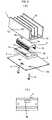
- FIG. 4is a transverse sectional view (a) of the controller represented in FIG. 1 , and a perspective view (b) of a unit composed of a heat shield, a printed circuit board, and electrolytic capacitors;
- FIG. 5is an exploded perspective view, viewed from the bottom face, of the controller represented in FIG. 4 ;
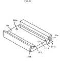
- FIG. 6is a perspective view illustrating a heat shield according to another embodiment of the present invention.
- FIG. 7is an exploded perspective view, viewed from the bottom face, of a controller according to another embodiment of the present invention.
- FIG. 8is a perspective view illustrating a controller according to another embodiment of the present invention.
- FIG. 9is a perspective view (a) illustrating a unit composed of a diode stack, a module, a heat shield, and a printed circuit board, and a perspective view (b) illustrating the heat shield.
- FIG. 1is an exploded perspective view illustrating a controller using a modular heat-radiation structure according to the embodiment of the present invention
- FIG. 2is an internal circuit diagram illustrating the controller represented in FIG. 1
- FIG. 3is an exploded perspective view illustrating the modular heat-radiation structure represented in FIG. 1 .
- a controller 1 using the modular heat-radiation structureincludes a printed circuit board 3 , chips 11 and electrolytic capacitors 15 mounted on the printed circuit board 3 , a power module 5 , fixed to the printed circuit board 3 through a heat shield 9 , in which a transistor generating heat is encapsulated, a heat-radiation fin 7 for radiating heat of the power module 5 , and a case 20 , composed of a bottom board 24 and a cover 22 formed stepwise to have two steps, for storing the heat shield 9 .
- the electrolytic capacitor 15is connected to the dc side of a diode stack 25 for converting an inputted ac voltage to a dc voltage
- the power module 5is connected as an inverter that can convert the dc voltage to an ac voltage having an arbitrary frequency
- a driver 12 having the chip 11 for driving the power module 5is connected.
- the modular heat-radiation structureincludes the plane printed-circuit-board 3 , the power module 5 having not only lead lines 5 L as a lead connected to a first main unit 5 a and the printed circuit board 3 by solder but also fixing holes 5 e provided in the approximately plane first-main-unit 5 a , and generating heat, the heat-radiation fin 7 , fixed to the upper face (top face) of the first main unit 5 a , not only having plane folds 7 b for radiating the heat generated in the module 5 but also being provided with screw holes 7 e , the plane heat shield 9 , which is inserted between the printed circuit board 3 and the first main unit 5 a , being resin-made and insulating, and screws 13 as a fixture for fixing the power module 5 with the heat-radiation fin 7 .
- the heat shield 9In the heat shield 9 , slit lead openings 9 L for allowing the lead lines 5 L to pass therethrough, first fixing holes 9 e for allowing the screw 13 to pass therethrough, and a concave 9 k for storing the chips 11 are provided.
- the heat shield 9is formed in such a way that its thickness is thinner than a length obtained by subtracting the thickness of the printed circuit board 3 from the longitudinal length of the lead line 5 L.
- a through holemay also be provided other than the concave 9 k ; however, the reason why the concave 9 k is applied is because the radiation of the heat generated from the bottom of the power module 5 to a plurality of the chips 11 and the printed circuit board 3 positioning on the bottom of the power module is intended to be prevented.
- second fixing holes 3 efor allowing the screws 13 to pass therethrough are provided.
- Such configured modular heat-radiation structurecan be obtained as follows.
- the heat shield 9is mounted in such a way that the concave 9 k positions on the chips 11 mounted on the printed circuit board 3 , the lead lines 5 L of the power module 5 are passed through the lead openings 9 L of the heat shield 9 , the lead lines 5 L are also passed through through-holes, which are not illustrated in the figure, of the printed circuit board 3 , and then soldering is performed.
- the screws 13are screwed, through the second fixing holes 3 e of the printed circuit board 3 , the first fixing holes 9 e of the heat shield 9 , and the fixing holes 5 e of the power module 5 , into the screw holes 7 e of the heat-radiation fin 7 .
- the power module 5operates and generates heat.
- the heat generatedis conducted to the heat-radiation fin 7 from the top face of the main unit 5 a of the power module 5 , and then radiated from the surface of the heat-radiation fin 7 .
- the radiation heat generated from the bottom of the main unit 5 a of the power module 5is shielded by the heat shield 9 . Therefore, almost of the heat generated from the main unit 5 a of the power module 5 is conducted to the heat-radiation fin 7 , and radiated thereby to the outdoor air; moreover, a heat amount radiated to the chips 11 and the printed circuit board 3 is reduced by the heat shield 9 . Consequently, thermal deformation of the printed circuit board 3 is to be relaxed.
- FIG. 4is a transverse sectional view (a) of the controller represented in FIG. 1 , and a perspective view (b) of a unit composed of a heat shield, a printed circuit board, and electrolytic capacitors; and
- FIG. 5is an exploded perspective view, viewed from the bottom face, of the controller represented in FIG. 4 .
- the same symbols in FIG. 4 and FIG. 5 as those in FIG. 1-FIG . 3are assigned to the same or equivalent elements, and the explanation is omitted.
- the controlleris characterized to be separated into a non heat-generation portion in which the electrolytic capacitors 15 , etc. whose heat generation is relatively insignificant are installed inside the case 20 , and a heat-generation portion in which the heat generation such as the power module 5 is larger than that of the electrolytic capacitors 15 .
- the heat-generation portion and the non heat-generation portionare separated by a division formed by a side wall 22 t of the cover 22 , to be the vertical portion between the first level to the second level of the case 20 , and by protrusions 111 t of a heat shield 111 .
- the divisionmay be formed by either the side wall 22 t of the cover 22 or the protrusions 111 t.
- the heat-radiation fin 7has a convex face 7 f contacting the bottom of the power module 5 .
- the case 20includes the plane bottom board 24 and the cover 22 , and the bottom board 24 is provided with a vertically arranged piece 24 rectangularly and vertically arranged around the entire periphery of the bottom board.
- the stepwise structured cover 22 having the first level 22 a and the second level 22 chas a mouth 22 e , for protrude the folds 7 b of the heat-radiation fin 7 , which is obtained by opening the upper face of the first level, and has a plurality of slits 22 s in the upper face of the second level whose bottom is opened.
- the heat shield 111is provided with slit lead openings 111 L for allowing the lead lines 5 L of the power module 5 to pass therethrough, first fixing holes 111 e for allowing the screws 13 to pass therethrough, and the protrusions 111 t that are vertically arranged at the peripheries of the heat shield.
- two protrusions 111 tare provided in this example, only the protrusion close to the side wall 22 t of the cover may be provided. Thereby, the division described as above can be formed.
- the radiation heat generated in the power module 5 provided inside the heat-generation portionbecomes difficult to conduct to the electrolytic capacitors 15 provided inside the non heat-generation portion.
- the heat-generation portion and the non heat-generation portionare especially and thermally and separated each other. That is, by providing a gap g inside the U-shaped portion 111 u of the heat shield 111 , the heat-generation portion and the non heat-generation portion are further separated each other.
- a case 220is made of resin as represented in FIG. 7 , a mouth 220 e of the case 220 is formed slightly larger than the first main unit 5 a of the power module 5 , and a top 220 d facing close to the bottom of the heat-radiation fin 7 is provided around the mouth 220 e.
- the heat-radiation fin 7is heated by heat conducted from the power module 5 ; consequently, the radiation heat accompanying the heating of the fin becomes difficult to radiate the module 5 , etc.
- FIG. 8is a perspective view illustrating a controller according to the other embodiment; meanwhile, FIG. 9 is a perspective view (a) illustrating a unit composed of a diode stack, a module, a heat shield, and a printed circuit board, and a perspective view (b) illustrating the heat shield.
- FIG. 8 and FIG. 9are assigned to the same or equivalent elements, and the explanation is omitted.
- the controlleris provided with the printed circuit board 3 , the heat-generating diode stack 25 having a rectangularly-and-vertically-arranged second main unit 25 h whose lead lines 25 L as the lead are fixed to the printed circuit board 3 , the heat-radiation fin 7 having a mouth 7 h for protruding the second main unit 25 h of the diode stack 25 and also having the folds 7 b , and a clip 301 , having elasticity towards the open/close movement, for contacting the folds 7 b to the second main unit 25 h of the diode stack 25 .
- a mouth 211 f for allowing the second main unit 25 h of the diode stack 25 to pass therethroughis provided, and protrusions 211 t are also provided for supporting the second main unit 25 h towards the longitudinal orientation of the mouth 211 f.
- the heat-radiation fin 7can be commonly used for the diode stack 25 and the power module 5 , and using the clip 301 heat generated in the second main unit 25 h of the diode stack 25 can also be radiated from the heat-radiation fin 7 .
- the lead lines 25 L of the diode stack 25are passed through the mouth 211 f of the heat shield 211 , and the lead lines 25 L are fixed to the printed circuit board 3 with the second main unit 25 h being picked by the protrusions 211 t . Therefore, because the main unit 25 h of the diode stack 25 can be supported by the protrusions 211 t of the heat shield 211 , when the diode stack is fixed to the printed circuit board 3 , the main unit 25 h of the diode stack 25 is configured to be rigid.
- the modular heat-radiation structure and the controller including the structure according to the present inventionare applicable to control motors.
Landscapes
- Engineering & Computer Science (AREA)
- Microelectronics & Electronic Packaging (AREA)
- Physics & Mathematics (AREA)
- Condensed Matter Physics & Semiconductors (AREA)
- General Physics & Mathematics (AREA)
- Computer Hardware Design (AREA)
- Power Engineering (AREA)
- Manufacturing & Machinery (AREA)
- Cooling Or The Like Of Electrical Apparatus (AREA)
- Cooling Or The Like Of Semiconductors Or Solid State Devices (AREA)
- Shielding Devices Or Components To Electric Or Magnetic Fields (AREA)
Abstract
Description
Claims (5)
Applications Claiming Priority (1)
| Application Number | Priority Date | Filing Date | Title |
|---|---|---|---|
| PCT/JP2004/003811WO2005091692A1 (en) | 2004-03-18 | 2004-03-18 | Module heat radiation structure and control device using the same |
Publications (2)
| Publication Number | Publication Date |
|---|---|
| US20070139896A1 US20070139896A1 (en) | 2007-06-21 |
| US7746648B2true US7746648B2 (en) | 2010-06-29 |
Family
ID=34994103
Family Applications (1)
| Application Number | Title | Priority Date | Filing Date |
|---|---|---|---|
| US10/591,134Expired - Fee RelatedUS7746648B2 (en) | 2004-03-18 | 2004-03-18 | Modular heat-radiation structure and controller including the structure |
Country Status (5)
| Country | Link |
|---|---|
| US (1) | US7746648B2 (en) |
| JP (1) | JP4360404B2 (en) |
| CN (1) | CN100525599C (en) |
| TW (1) | TWI238038B (en) |
| WO (1) | WO2005091692A1 (en) |
Cited By (5)
| Publication number | Priority date | Publication date | Assignee | Title |
|---|---|---|---|---|
| US20100195284A1 (en)* | 2006-12-11 | 2010-08-05 | Danfoss Drives A/S | Electronic device and frequency converter of motor |
| US20100202109A1 (en)* | 2006-12-11 | 2010-08-12 | Li Zheng | Electronic device and frequency converter of motor |
| US20120249031A1 (en)* | 2011-04-04 | 2012-10-04 | Schneider Toshiba Inverter Europe Sas | Variable speed drive with optimized architecture |
| US20180019186A1 (en)* | 2015-04-08 | 2018-01-18 | Mitsubishi Electric Corporation | Semiconductor device and manufacturing method of semiconductor device |
| US11547018B2 (en)* | 2019-07-09 | 2023-01-03 | Kioxia Corporation | Semiconductor storage device |
Families Citing this family (25)
| Publication number | Priority date | Publication date | Assignee | Title |
|---|---|---|---|---|
| JP4780349B2 (en)* | 2006-10-06 | 2011-09-28 | 株式会社安川電機 | Power module mounting structure and motor control device including the same |
| JP5586866B2 (en) | 2008-09-29 | 2014-09-10 | 株式会社日立産機システム | Power converter |
| TWI377465B (en)* | 2010-03-11 | 2012-11-21 | Delta Electronics Inc | Heat dissipating module and electronic device using such heat dissipating module |
| DE102010028927A1 (en)* | 2010-05-12 | 2011-11-17 | Zf Friedrichshafen Ag | Power electronics arrangement |
| JP2012099855A (en)* | 2012-02-06 | 2012-05-24 | Daikin Ind Ltd | Electric power conversion apparatus |
| JP6015405B2 (en)* | 2012-12-12 | 2016-10-26 | 富士電機株式会社 | servo amplifier |
| JP6260178B2 (en)* | 2013-10-01 | 2018-01-17 | オムロン株式会社 | Enclosure and electrical equipment |
| CN104682670B (en)* | 2013-11-26 | 2017-12-12 | 台达电子企业管理(上海)有限公司 | Power conversion device and its power conversion board assembly |
| CN103697039A (en)* | 2013-12-10 | 2014-04-02 | 深圳市正弦电气股份有限公司 | Combined screw |
| JP6295746B2 (en)* | 2014-03-14 | 2018-03-20 | オムロン株式会社 | Electronics |
| JP6269203B2 (en)* | 2014-03-14 | 2018-01-31 | オムロン株式会社 | Electronics |
| JP6432137B2 (en)* | 2014-03-14 | 2018-12-05 | オムロン株式会社 | Electronics |
| JP5929958B2 (en)* | 2014-05-07 | 2016-06-08 | 株式会社デンソー | Electronic equipment |
| JP6168362B2 (en)* | 2014-09-05 | 2017-07-26 | 株式会社オートネットワーク技術研究所 | Circuit structure, electrical junction box and spacer |
| JP6330053B2 (en)* | 2014-10-29 | 2018-05-30 | 新電元工業株式会社 | Heat dissipation structure |
| WO2016067393A1 (en)* | 2014-10-29 | 2016-05-06 | 新電元工業株式会社 | Heat-dissipating structure |
| WO2016067383A1 (en)* | 2014-10-29 | 2016-05-06 | 新電元工業株式会社 | Heat-dissipating structure |
| WO2016067390A1 (en)* | 2014-10-29 | 2016-05-06 | 新電元工業株式会社 | Heat-dissipating structure |
| JP6458575B2 (en)* | 2015-03-17 | 2019-01-30 | 富士電機株式会社 | Power converter |
| US9652008B2 (en)* | 2015-04-02 | 2017-05-16 | Det International Holding Limited | Power module |
| FR3083958B1 (en)* | 2018-07-16 | 2021-01-15 | Continental Automotive France | THERMAL DISSIPATION DEVICE EQUIPPED WITH A SECONDARY COLD PLATE |
| CN110841741A (en)* | 2019-12-20 | 2020-02-28 | 凡知医疗科技(江苏)有限公司 | Reversible micro-fluidic chip anchor clamps |
| KR102310025B1 (en)* | 2019-12-27 | 2021-10-07 | 주식회사 유라코퍼레이션 | High Voltage Devices |
| CN111601495B (en)* | 2020-06-02 | 2021-12-14 | 广州视源电子科技股份有限公司 | A kind of assembly method of PCBA component, assembly fixture and PCBA component |
| CN113035807B (en)* | 2021-03-08 | 2022-05-27 | 广东神思半导体有限公司 | Triode with stable heat radiation structure |
Citations (16)
| Publication number | Priority date | Publication date | Assignee | Title |
|---|---|---|---|---|
| JPS4329597Y1 (en) | 1966-04-16 | 1968-12-04 | ||
| JPS5047370A (en) | 1973-02-12 | 1975-04-26 | ||
| US3880493A (en)* | 1973-12-28 | 1975-04-29 | Burroughs Corp | Capacitor socket for a dual-in-line package |
| JPS5461561U (en) | 1977-10-07 | 1979-04-28 | ||
| US4636918A (en)* | 1982-07-30 | 1987-01-13 | Rogers Corporation | Decoupled integrated circuit package |
| US4941069A (en)* | 1988-07-07 | 1990-07-10 | Zenith Electronics Corporation | Rectifier spacer/mounting assembly |
| US5001601A (en)* | 1990-01-30 | 1991-03-19 | Grumman Aerospace Corporation | Modular cooling fixture for power transistors |
| US5237485A (en)* | 1985-04-26 | 1993-08-17 | Sgs Microelettronica S.P.A. | Apparatus and method for improved thermal coupling of a semiconductor package to a cooling plate and increased electrical coupling of package leads on more than one side of the package to a circuit board |
| US5546275A (en)* | 1994-09-23 | 1996-08-13 | Motorola, Inc. | Electrical module mounting apparatus |
| US5703752A (en)* | 1994-08-23 | 1997-12-30 | Samsung Electro-Mechanics Co., Ltd. | Heat dissipating apparatus for a semiconductor device for use in a motor drive |
| US6067231A (en)* | 1998-11-10 | 2000-05-23 | Acer Peripherals, Inc. | Heat-dissipating structure for an electrical device |
| JP2002111250A (en) | 2000-09-29 | 2002-04-12 | Matsushita Electric Ind Co Ltd | Fixed spacer and air conditioner using the fixed spacer |
| JP2002330523A (en) | 2001-04-27 | 2002-11-15 | Yazaki Corp | Heat conduction prevention structure of electrical junction box |
| US6487078B2 (en)* | 2000-03-13 | 2002-11-26 | Legacy Electronics, Inc. | Electronic module having a three dimensional array of carrier-mounted integrated circuit packages |
| US7206204B2 (en)* | 2003-12-19 | 2007-04-17 | Hitachi Industrial Equipment Systems Co., Ltd. | Electric circuit module |
| US7360586B2 (en)* | 2003-07-31 | 2008-04-22 | Fujitsu Limited | Wrap around heat sink apparatus and method |
Family Cites Families (1)
| Publication number | Priority date | Publication date | Assignee | Title |
|---|---|---|---|---|
| JPS5233822Y2 (en)* | 1973-08-29 | 1977-08-02 |
- 2004
- 2004-03-18JPJP2006511100Apatent/JP4360404B2/ennot_activeExpired - Fee Related
- 2004-03-18USUS10/591,134patent/US7746648B2/ennot_activeExpired - Fee Related
- 2004-03-18CNCN200480042480.2Apatent/CN100525599C/ennot_activeExpired - Fee Related
- 2004-03-18WOPCT/JP2004/003811patent/WO2005091692A1/enactiveApplication Filing
- 2004-03-31TWTW093108814Apatent/TWI238038B/ennot_activeIP Right Cessation
Patent Citations (16)
| Publication number | Priority date | Publication date | Assignee | Title |
|---|---|---|---|---|
| JPS4329597Y1 (en) | 1966-04-16 | 1968-12-04 | ||
| JPS5047370A (en) | 1973-02-12 | 1975-04-26 | ||
| US3880493A (en)* | 1973-12-28 | 1975-04-29 | Burroughs Corp | Capacitor socket for a dual-in-line package |
| JPS5461561U (en) | 1977-10-07 | 1979-04-28 | ||
| US4636918A (en)* | 1982-07-30 | 1987-01-13 | Rogers Corporation | Decoupled integrated circuit package |
| US5237485A (en)* | 1985-04-26 | 1993-08-17 | Sgs Microelettronica S.P.A. | Apparatus and method for improved thermal coupling of a semiconductor package to a cooling plate and increased electrical coupling of package leads on more than one side of the package to a circuit board |
| US4941069A (en)* | 1988-07-07 | 1990-07-10 | Zenith Electronics Corporation | Rectifier spacer/mounting assembly |
| US5001601A (en)* | 1990-01-30 | 1991-03-19 | Grumman Aerospace Corporation | Modular cooling fixture for power transistors |
| US5703752A (en)* | 1994-08-23 | 1997-12-30 | Samsung Electro-Mechanics Co., Ltd. | Heat dissipating apparatus for a semiconductor device for use in a motor drive |
| US5546275A (en)* | 1994-09-23 | 1996-08-13 | Motorola, Inc. | Electrical module mounting apparatus |
| US6067231A (en)* | 1998-11-10 | 2000-05-23 | Acer Peripherals, Inc. | Heat-dissipating structure for an electrical device |
| US6487078B2 (en)* | 2000-03-13 | 2002-11-26 | Legacy Electronics, Inc. | Electronic module having a three dimensional array of carrier-mounted integrated circuit packages |
| JP2002111250A (en) | 2000-09-29 | 2002-04-12 | Matsushita Electric Ind Co Ltd | Fixed spacer and air conditioner using the fixed spacer |
| JP2002330523A (en) | 2001-04-27 | 2002-11-15 | Yazaki Corp | Heat conduction prevention structure of electrical junction box |
| US7360586B2 (en)* | 2003-07-31 | 2008-04-22 | Fujitsu Limited | Wrap around heat sink apparatus and method |
| US7206204B2 (en)* | 2003-12-19 | 2007-04-17 | Hitachi Industrial Equipment Systems Co., Ltd. | Electric circuit module |
Cited By (9)
| Publication number | Priority date | Publication date | Assignee | Title |
|---|---|---|---|---|
| US20100195284A1 (en)* | 2006-12-11 | 2010-08-05 | Danfoss Drives A/S | Electronic device and frequency converter of motor |
| US20100202109A1 (en)* | 2006-12-11 | 2010-08-12 | Li Zheng | Electronic device and frequency converter of motor |
| US8310830B2 (en)* | 2006-12-11 | 2012-11-13 | Danfoss Drives A/S | Electronic device and frequency converter of motor |
| US8363408B2 (en) | 2006-12-11 | 2013-01-29 | Danfoss Drives A/S | Electronic device and frequency converter of motor |
| US20120249031A1 (en)* | 2011-04-04 | 2012-10-04 | Schneider Toshiba Inverter Europe Sas | Variable speed drive with optimized architecture |
| US8810178B2 (en)* | 2011-04-04 | 2014-08-19 | Schneider Toshiba Inverter Europe Sas | Variable speed drive with optimized architecture |
| US20180019186A1 (en)* | 2015-04-08 | 2018-01-18 | Mitsubishi Electric Corporation | Semiconductor device and manufacturing method of semiconductor device |
| US10269681B2 (en)* | 2015-04-08 | 2019-04-23 | Mitsubishi Electric Corporation | Semiconductor device and manufacturing method of semiconductor device |
| US11547018B2 (en)* | 2019-07-09 | 2023-01-03 | Kioxia Corporation | Semiconductor storage device |
Also Published As
| Publication number | Publication date |
|---|---|
| CN1926932A (en) | 2007-03-07 |
| TWI238038B (en) | 2005-08-11 |
| US20070139896A1 (en) | 2007-06-21 |
| TW200533275A (en) | 2005-10-01 |
| JPWO2005091692A1 (en) | 2008-02-07 |
| JP4360404B2 (en) | 2009-11-11 |
| CN100525599C (en) | 2009-08-05 |
| WO2005091692A1 (en) | 2005-09-29 |
Similar Documents
| Publication | Publication Date | Title |
|---|---|---|
| US7746648B2 (en) | Modular heat-radiation structure and controller including the structure | |
| JP5141991B2 (en) | Motor control device | |
| US7120024B2 (en) | Electronic control device | |
| US7006356B2 (en) | Driving system with converter control for low-voltage three-phase motors | |
| WO2014020806A1 (en) | Cooling structure and power converter | |
| JP2005183644A (en) | Electrical circuit module | |
| KR101228841B1 (en) | A springy clip type apparatus for fastening power semiconductor | |
| JP5529477B2 (en) | Inverter-integrated electric compressor | |
| WO2008026516A1 (en) | Electric component unit | |
| US20220263305A1 (en) | Circuit structure | |
| JP2015053776A (en) | Electric power conversion system | |
| JP4387314B2 (en) | Electrical junction box | |
| CN214544075U (en) | Power conversion device | |
| CN104040865A (en) | Power conversion apparatus | |
| JP6910315B2 (en) | Electric compressor | |
| JPH0775215A (en) | Motor drive device for electric vehicle | |
| US20230247764A1 (en) | Electronic control module | |
| JP2017108007A (en) | Heat radiation structure for heat evolution electronic component and manufacturing method for the same | |
| JP2000014150A (en) | Power switching apparatus and its assembling method | |
| JP6884244B1 (en) | Power converter | |
| EP1003215A2 (en) | Heat sink with integral self-locking clamp | |
| JP4800283B2 (en) | Wiring block storage structure | |
| JP2010108879A (en) | Electric equipment and luminaire | |
| JP7466850B2 (en) | On-board chargers and inverters | |
| JP6771835B2 (en) | Power converter |
Legal Events
| Date | Code | Title | Description |
|---|---|---|---|
| AS | Assignment | Owner name:MITSUBISHI ELECTRIC CORPORATION, JAPAN Free format text:ASSIGNMENT OF ASSIGNORS INTEREST;ASSIGNORS:YAMADA, HIROSHI;ABE, TOMONORI;TAKIKOSHI, KEIICHI;REEL/FRAME:018308/0584 Effective date:20060713 Owner name:MITSUBISHI ELECTRIC CORPORATION,JAPAN Free format text:ASSIGNMENT OF ASSIGNORS INTEREST;ASSIGNORS:YAMADA, HIROSHI;ABE, TOMONORI;TAKIKOSHI, KEIICHI;REEL/FRAME:018308/0584 Effective date:20060713 | |
| FEPP | Fee payment procedure | Free format text:PAYOR NUMBER ASSIGNED (ORIGINAL EVENT CODE: ASPN); ENTITY STATUS OF PATENT OWNER: LARGE ENTITY | |
| STCF | Information on status: patent grant | Free format text:PATENTED CASE | |
| FPAY | Fee payment | Year of fee payment:4 | |
| FEPP | Fee payment procedure | Free format text:MAINTENANCE FEE REMINDER MAILED (ORIGINAL EVENT CODE: REM.) | |
| LAPS | Lapse for failure to pay maintenance fees | Free format text:PATENT EXPIRED FOR FAILURE TO PAY MAINTENANCE FEES (ORIGINAL EVENT CODE: EXP.); ENTITY STATUS OF PATENT OWNER: LARGE ENTITY | |
| STCH | Information on status: patent discontinuation | Free format text:PATENT EXPIRED DUE TO NONPAYMENT OF MAINTENANCE FEES UNDER 37 CFR 1.362 | |
| FP | Lapsed due to failure to pay maintenance fee | Effective date:20220629 |