US7746055B2 - Current measuring device - Google Patents
Current measuring deviceDownload PDFInfo
- Publication number
- US7746055B2 US7746055B2US12/249,547US24954708AUS7746055B2US 7746055 B2US7746055 B2US 7746055B2US 24954708 AUS24954708 AUS 24954708AUS 7746055 B2US7746055 B2US 7746055B2
- Authority
- US
- United States
- Prior art keywords
- recess
- coupled
- current
- hall effect
- current sensor
- Prior art date
- Legal status (The legal status is an assumption and is not a legal conclusion. Google has not performed a legal analysis and makes no representation as to the accuracy of the status listed.)
- Expired - Fee Related, expires
Links
Images


Classifications
- G—PHYSICS
- G01—MEASURING; TESTING
- G01R—MEASURING ELECTRIC VARIABLES; MEASURING MAGNETIC VARIABLES
- G01R15/00—Details of measuring arrangements of the types provided for in groups G01R17/00 - G01R29/00, G01R33/00 - G01R33/26 or G01R35/00
- G01R15/14—Adaptations providing voltage or current isolation, e.g. for high-voltage or high-current networks
- G01R15/20—Adaptations providing voltage or current isolation, e.g. for high-voltage or high-current networks using galvano-magnetic devices, e.g. Hall-effect devices, i.e. measuring a magnetic field via the interaction between a current and a magnetic field, e.g. magneto resistive or Hall effect devices
- G01R15/202—Adaptations providing voltage or current isolation, e.g. for high-voltage or high-current networks using galvano-magnetic devices, e.g. Hall-effect devices, i.e. measuring a magnetic field via the interaction between a current and a magnetic field, e.g. magneto resistive or Hall effect devices using Hall-effect devices
Definitions
- the present inventionrelates generally to a device for the noninvasive measurement of electrical current through a conductor and in particular to a device the has a sensor with a clamping mechanism that holds an electrical conductor against a Hall effect sensor.
- Electrical poweris typically produced at centralized power production facilities and transferred at high voltages to local substations.
- the local substationstransform the electrical power to a medium or low voltage.
- the electrical poweris subsequently distributed through feeders to local distribution networks. The power is thus delivered to end customer that consumes the electrical power.
- a number of control devicesare used within the transmission system such as fuses, transformers, circuit breakers, reclosers and protective relays. These devices help control the flow of electrical power and provide functionality for removing electrical power in the event of an electrical fault.
- a protective relayis one type device that detects undesirable electrical conditions, such as high voltage for example.
- the protective relayoperates in conjunction with a circuit breaker for interrupting the flow of electrical current when the undesired condition is detected.
- Protective relayshave selectable time/current curves that allow the operator to have a fine level of control over the triggering conditions.
- One type of protective relayuses elaborate electromechanical components, such as arrays of induction disks or induction cylinders, shaded-pole magnets, operating and restraint coils, solenoid-type operators, and phase-shifting networks to allow the relay to respond to such conditions as over-current, over-voltage, reverse power flow, over-frequency and under-frequency.
- Protective relaysmay even be arranged to provide trip functionality for faults up to a certain distance away from a substation but not beyond that point by measuring the apparent impedance.
- the electromechanical type protective relayWhen a fault occurs, the electromechanical type protective relay provides a signal to the circuit breaker to interrupt the current flow. An indicator, such as a visual flag, is then displayed on the relay to indicate the detection of the undesired condition.
- repair personnelneed to physically visit the substation where the relays are located and determine which protective relay operated. As a substation having many protective relays may cover a wide geographic area, the process of physically identifying the relay may be time consuming and costly.
- a current measuring devicehaving a base with a generally hollow interior portion.
- a coveris coupled to the base.
- An armis coupled to the cover.
- a clampis coupled to the arm, the clamp having a first semi-circular recess on one side of the arm and a lever portion on a side of the clamp opposite the first semi-circular recess.
- a semi-circular mu-metal memberis coupled to the first semi-circular recess.
- a Hall effect sensoris coupled to the base adjacent the first semi-circular recess.
- a removable current sensorhaving a housing.
- a clampis coupled to the housing, the clamp having a locking portion on one end and a lever arm on an opposite end.
- the clampis also rotatable between a first position wherein the locking portion is in contact with the housing, and a second position.
- a Hall effect sensorhaving a first end is mounted to the housing, the Hall effect sensor further includes a second end positioned adjacent the clamp locking portion.
- a biasing memberis coupled between the housing and the lever arm, the biasing member is arranged to rotate the clamp locking portion towards the Hall effect sensor. 7
- a current sensor for measuring electrical current flow through an electrical conductoris also provided.
- the current sensorincludes a clamp member.
- the clamp memberhas a lever arm on one end and a first recess on an opposite end. The first recess being sized to receive the electrical conductor.
- a pivot armis rotatably coupled to the clamp member between the lever arm and the recess.
- a housingis coupled to the pivot arm, the housing includes a hollow interior portion and an opening adjacent the first recess.
- a Hall effect sensoris positioned within the opening and mounted on one end to the housing within the hollow interior.
- a mu-metal insertis coupled to said first recess. The mu-metal insert is sized to receive the electrical conductor.
- FIG. 1is a schematic illustration of a current sensor in accordance with an exemplary embodiment
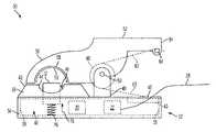
- FIG. 2is a side plan view illustration of another embodiment current sensor
- FIG. 3is a side plan view illustration of another embodiment current sensor having a Hall effect sensor mounted to a biasing member;
- FIG. 4is a side plan view illustration of another embodiment current sensor having a fastening arrangement
- FIG. 5is a side plan view illustration of the current sensor of FIG. 4 in the locked position
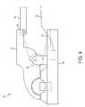
- FIG. 6is a side plan view illustration of another embodiment current sensor having a fastening arrangement
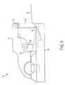
- FIG. 7is a side plan view illustration of another embodiment current sensor having another fastening arrangement
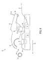
- FIG. 8is a side plan view illustration of the current sensor of FIG. 2 in an open position
- FIG. 9is a side plan view illustration of the current sensor of FIG. 2 coupled to an electrical conductor.
- FIG. 10is a side plan view illustration of an alternate embodiment current sensor having wireless connectivity.
- FIG. 1illustrates an exemplary embodiment of a current sensor device 10 .
- the current sensor 10includes a Hall effect device 12 that is placed in contact with an electrical conductor 14 by a clamping force (F) 16 .
- the Hall effect device 12is an integrated circuit that includes a transducer that varies its output voltage in response to changes in a magnetic field.
- a magnetic field (H) 18is created.
- the Hall effect sensorproduces an electrical signal that is proportional to the magnetic field 18 and the electrical current flowing through the electrical conductor 14 .
- Hall effect sensor 12is capable of sensing a current between 0.2 to 40.0 amps passing through electrical conductor 14 .
- a current sensing circuit 20is electrically coupled to receive a signal from the Hall effect sensor 12 . It should be appreciated that the sensing circuit 20 may be integrated as a single package with the integrated circuit of the Hall effect sensor 12 .
- the sensing circuit 20transmits a signal indicative of the current flowing through electrical conductor 14 to a signal conditioning circuit 22 .
- the conditioning circuitmodifies the signal from the sensing circuit 20 , such as through amplification for example, and prepares the signal for transmission to a data acquisition system 24 .
- the signalis transmitted between the conditioning circuit 22 and the data acquisition system 24 over a data transmission medium 28 that carries both power and data.
- Data transmission media 28includes, but is not limited to, twisted pair wiring, coaxial cable, and fiber optic cable. Data transmission media 28 also includes, but is not limited to, wireless, radio and infrared signal transmission systems.
- the data acquisition system 24may be a dedicated acquisition system, or alternatively may be a general-purpose computer having executable software for receiving signals from the current sensor 10 .
- the data acquisition system 24may be microprocessor, microcomputer, a minicomputer, an optical computer, a board computer, a complex instruction set computer, an ASIC (application specific integrated circuit), a reduced instruction set computer, an analog computer, a digital computer, a molecular computer, a quantum computer, a cellular computer, a superconducting computer, a supercomputer, a solid-state computer, a single-board computer, a buffered computer, a computer network, a desktop computer, a laptop computer, or a hybrid of any of the foregoing.
- Data acquisition system 24is capable of converting the analog voltage or current level provided by current sensor 10 into a digital signal indicative of the level of the amount of electrical power flowing through conductor 14 .
- current sensor 10may be configured to provide a digital signal to data acquisition system 24 , or an analog-to-digital (A/D) converter (not shown) maybe coupled between current sensor 10 and data acquisition system 24 to convert the analog signal provided by current sensor 10 into a digital signal for processing by data acquisition system 24 .
- A/Danalog-to-digital
- additional components and circuitsmay be arranged between the current sensor 10 and the data acquisition system 24 without deviating from the intended scope of the claimed invention.
- the current sensor 30has a housing 32 with a base 34 and a cover 36 .
- the cover 36couples to the base 34 by a snap fit.
- the cover 36may also couple to the base 34 by other methods known in the art, such as mechanical fasteners, screws, or bonded with an adhesive for example.
- the base 34 and cover 36are made from a nonconductive plastic material such as polypropylene, polyethylene or polycarbonate for example.
- the base 34has walls 38 that form a generally hollow interior portion 40 .
- the interior portion 40may include pockets (not shown) that are integrally formed in the base 34 .
- the pocketsmay be used to mount components, such as Hall effect sensor 12 , current sensor circuit 20 or signal conditioning circuit 22 for example, as is known in the art.
- the cover 36includes a raised portion 42 having a semi-circular recess 44 .
- An opening 46 in the recess 44allows the Hall effect sensor 12 to be mounted inside the base 34 and extend past the surface of the recess 44 .
- a slot 43is formed in the top surface 45 of cover 36 .
- the slot 43is sized to receive a cable from transmission medium 28 .
- openings for the transmission medium cablemay also be located in the base 34 such as in the walls 38 for example.
- An arm 48extends past the top surface 45 of the cover 36 adjacent the raised portion 42 .
- the arm 48may be formed in the cover 36 , the base 34 or be formed as a separate component and mounted to either the cover 36 or the base 34 .
- the arm 48extends past the top surface of the raised portion 42 and includes a hole sized to receive a pin 50 .
- the pin 50provides a pivot to allow rotation of a clamp 52 . It should be appreciated that while only one arm 48 is illustrated, in one embodiment, there are two arms 48 arranged on either side of the clamp 52 .
- the clamp 52is rotatably coupled to the housing 32 by the pin 50 .
- the clamp 52is made from a nonconductive plastic material and may be made from the same material as the housing 32 .
- the clamp 52includes a lever portion 54 on one end and a locking portion 56 on an opposite end.
- the locking portionincludes a recess 58 adjacent the raised portion 42 .
- the recess 58is sized to receive a mu-metal device 59 .
- the mu-metal device 59is a thin walled member that extends the width of the clamp 52 .
- the mu-metal device 59may be coupled in the recess 58 such as by insert molding or by bonding for example.
- a mu-metalis typically a nickel-iron alloy (75% nickel, 15% iron, plus copper and molybdenum) that has very high magnetic permeability. As will be discussed in more detail below, the high permeability makes the mu-metal device 59 effective at screening static or low frequency magnetic fields.
- a biasing member 60such as a spring for example, is captured on the pin 50 .
- the biasing member 60is a torsion spring having a first arm 62 coupled to the lever portion 54 by a pin 64 .
- a second arm 63extends from the biasing member 60 and contacts the top surface 45 .
- the biasing member 60is arranged to bias the clamp 52 such that the recess 58 rotates toward the raised portion 42 .
- the Hall effect sensor 12is not mounted directly to the base 34 , but rather is mounted to a biasing member 76 .
- the biasing member 76couples to Hall effect sensor 12 to the base 34 and provides a biasing force in the direction of arrow 78 .
- the biasing member 76is an elastically compliant member that allows the Hall effect sensor 12 to move relative to the base and the recessed area 44 .
- the biasing member 76may be a spring such as a compression spring for example.
- biasing member 76allows the top surface of the Hall effect sensor 12 to move in response to the diameter of the electrical conductor. For example, when the current sensor 30 is coupled to an electrical conductor having a larger diameter, the biasing member 76 compresses allowing the electrical conductor to seat within the recessed area 44 with the Hall effect sensor 12 remaining in contact with the conductor. Thus the biasing member 76 provides advantages in allowing the Hall effect sensor to securely contact a range of electrical conductor diameters.
- a dial or locking clip 79is coupled to the pin 64 . Once the operator attaches the current sensor 30 to a conductor, the locking clip 79 is rotated about the pin 64 from the open position ( FIG. 4 ) to the locked position ( FIG. 5 ). When in the locked position, the locking clip 79 is in contact with the top surface of the base 34 . Thus, the lever portion 54 is prevented from rotation about the pin 50 and the clamp 52 cannot be opened.
- a flexible strip 80 having a hook-and-loop type fasteneris wrapped around the base 34 and locking portion 56 .
- the use of the hook-and-loop fastenerallows the flexible strip 80 to accommodate a variety of electrical conductor sizes.
- Flexible strip 80may also include a tag portion 82 that provides a writing area 84 . The operator to identify the electrical conductor being monitored may use the writing area 84 .
- a clip type fastener 86may be used as illustrated in FIG. 7 .
- a “C” type clip fastener 86has a first arm 88 and a second arm 90 that extend from a body portion 92 .
- the clip fastener 86is made from a flexible material that allows the arms 88 , 90 to elastically deform when the clip fastener 86 is pushed onto the current sensor 30 .
- At the end of each arm 88 , 90is a projection 94 that slides into a groove 96 , 98 in the locking portion 56 and the base 34 respectively.
- the clip fastener second arm 90is coupled to the base 34 by a hinge. To secure the current sensor 30 , the clip fastener 86 is rotated about the hinge until the projection 94 on first arm 88 contacts the groove 96 .
- FIG. 8 and FIG. 9the installation and operation of the current sensor 30 will be described.
- the operatorapplies a force, as represented by arrow 66 .
- the operatormay squeeze the current sensor 30 between their thumb and index fingers, similar to a clothespin for example, to apply the force 66 .
- the clamp 52rotates about the pin 50 . This rotation creates a gap 68 between the raised portion 42 and the bottom surface of the clamp 52 .
- the current sensor 30is then moved in the direction represented by arrow 70 until the electrical conductor 14 is adjacent the Hall effect sensor 12 .
- the force 66is removed and the clamp locking portion 56 and recess 58 rotate in the opposite direction under the influence of biasing member 60 .
- the rotationcontinues until the mu-metal device 59 contacts the electrical conductor 14 . It should be appreciated that the clamping force created by the biasing member 60 is of sufficient level to maintain the current sensor 30 in the desired position during operation.
- the Hall effect sensor 12With the current sensor 30 clamped on electrical conductor 14 , the Hall effect sensor 12 is positioned within the influence of magnetic fields generated by electrical current flowing through the electrical conductor 14 . Since the mu-metal device 59 substantially surrounds the conductor 14 in the area of the Hall effect sensor 12 , any magnetic field detected by the Hall effect sensor 12 should be from the conductor 14 and not due to magnetic fields from surrounding or adjacent conductors and other electrical devices. Therefore, once electrical current flows through conductor 14 , Hall effect sensor 12 will generate a signal that is then processed by current sensing circuit 20 and signal conditioning circuit 22 before being transmitted by transmission media 28 . To remove the current sensor 30 , the operator once again applies the force 66 to the lever portion 54 and reverses the process. Thus, the current sensor 30 may be easily and repeatedly installed on electrical conductors.
- FIG. 10Another embodiment current sensor 72 is illustrated in FIG. 10 .
- an additional communications circuit 74is coupled to the output of signal conditioning circuit 22 .
- the communications circuit 74is coupled to an antenna 76 .
- the antenna 76transmits the signal wirelessly with electromagnetic radiation to data acquisition system 24 .
- communications circuit 74may transmit the signal using cellular, GSM, radio, infrared light, laser light or acoustic energy.
- the communications circuit 74may further comply with a variety of standards including but not limited to IEEE 802.11, IEEE 802.16, bluetooth, wireless universal serial bus, dedicated short range communications (DSRC) and communications, air-interface, long and medium range (CALM).
- DSRCdedicated short range communications
- CALMlong and medium range
- the antenna 76may be integrated with the communications circuit 74 , or alternatively positioned within the interior portion 40 .
- the use of a wireless connectionprovides an advantage in facilitating the installation of the current sensor 72 in equipment cabinets, such as where protective relays are located for example. This avoids the need to route cables or drill pass-through openings to allow the cable to exit the cabinet.
- Electrical power for operating the wireless current sensor 72may be provided by a self-powering current sensor.
- a self-powering current sensorsuch as a current transformer for example, generates electricity in proportion to electrical current flowing through its windings.
- the electrical powermay be provided by a power source such as a battery for example.
- the batteryis arranged in a clip fastener, such as the clip fastener 86 described in reference to FIG. 7 .
Landscapes
- Physics & Mathematics (AREA)
- General Physics & Mathematics (AREA)
- Measuring Instrument Details And Bridges, And Automatic Balancing Devices (AREA)
Abstract
Description
Claims (20)
Priority Applications (4)
| Application Number | Priority Date | Filing Date | Title |
|---|---|---|---|
| US12/249,547US7746055B2 (en) | 2008-10-10 | 2008-10-10 | Current measuring device |
| PCT/US2009/059498WO2010042424A1 (en) | 2008-10-10 | 2009-10-05 | Current measuring device |
| CA2739424ACA2739424A1 (en) | 2008-10-10 | 2009-10-05 | Current measuring device |
| EP09819704AEP2359150A1 (en) | 2008-10-10 | 2009-10-05 | Current measuring device |
Applications Claiming Priority (1)
| Application Number | Priority Date | Filing Date | Title |
|---|---|---|---|
| US12/249,547US7746055B2 (en) | 2008-10-10 | 2008-10-10 | Current measuring device |
Publications (2)
| Publication Number | Publication Date |
|---|---|
| US20100090683A1 US20100090683A1 (en) | 2010-04-15 |
| US7746055B2true US7746055B2 (en) | 2010-06-29 |
Family
ID=42098280
Family Applications (1)
| Application Number | Title | Priority Date | Filing Date |
|---|---|---|---|
| US12/249,547Expired - Fee RelatedUS7746055B2 (en) | 2008-10-10 | 2008-10-10 | Current measuring device |
Country Status (4)
| Country | Link |
|---|---|
| US (1) | US7746055B2 (en) |
| EP (1) | EP2359150A1 (en) |
| CA (1) | CA2739424A1 (en) |
| WO (1) | WO2010042424A1 (en) |
Cited By (10)
| Publication number | Priority date | Publication date | Assignee | Title |
|---|---|---|---|---|
| US20100088057A1 (en)* | 2008-10-07 | 2010-04-08 | Kopaczewski Peter | Method for detection of a physical variable by way of a circuit breaker |
| US20100315066A1 (en)* | 2007-12-07 | 2010-12-16 | Yazaki Corporation | Current sensor |
| US20120092020A1 (en)* | 2010-10-18 | 2012-04-19 | Xin Zhou | Acoustic apparatus and acoustic sensor apparatus including a clamp |
| US9326399B2 (en) | 2014-03-21 | 2016-04-26 | Eaton Corporation | Electrical system and sensor attachment assembly and method therefor |
| US9372207B1 (en) | 2013-09-10 | 2016-06-21 | EKM Metering, Inc. | Power sensing transducer |
| US9933285B2 (en) | 2014-03-21 | 2018-04-03 | Eaton Intelligent Power Limited | Piezoelectric sensor assembly, and sensor attachment assembly and electrical system employing same |
| US9964625B2 (en) | 2011-06-27 | 2018-05-08 | General Electric Company | Electrical substation fault monitoring and diagnostics |
| US11237192B2 (en)* | 2016-11-11 | 2022-02-01 | Fluke Corporation | Non-contact current measurement system |
| US20220137099A1 (en)* | 2020-11-05 | 2022-05-05 | U-Haul International, Inc. | Non-Invasive Current Sensing Device |
| US11749977B2 (en)* | 2015-01-07 | 2023-09-05 | Gustav Klauke Gmbh | Cutting device for the severance of an electrical power cable, or of a strand section |
Families Citing this family (8)
| Publication number | Priority date | Publication date | Assignee | Title |
|---|---|---|---|---|
| CN102236044B (en)* | 2010-04-20 | 2014-05-07 | 安阳安科电器股份有限公司 | Pulse current sensor and surge wave recording lightning protection box manufactured by adopting same |
| EP2780996B1 (en)* | 2011-11-16 | 2018-11-14 | Vestas Wind Systems A/S | Protection of a permanent magnet generator |
| DE202013005356U1 (en)* | 2013-06-14 | 2014-09-15 | Eura Innovation Gmbh | Clamp Meter |
| JP2015206674A (en)* | 2014-04-21 | 2015-11-19 | 富士通株式会社 | Current measuring apparatus and current measuring method |
| CN203881834U (en)* | 2014-06-12 | 2014-10-15 | 国网上海市电力公司 | AC-DC current wireless monitoring equipment |
| DE202014007077U1 (en)* | 2014-09-04 | 2015-12-08 | EurA Consult AG | Clamp Meter |
| US10267833B2 (en) | 2016-11-02 | 2019-04-23 | Equinix, Inc. | Power monitoring probe for monitoring power distribution in an electrical system |
| DE102022001631B4 (en)* | 2022-05-10 | 2024-11-14 | Christian Meyer | current indicator for welding helmet |
Citations (16)
| Publication number | Priority date | Publication date | Assignee | Title |
|---|---|---|---|---|
| US3219930A (en) | 1961-10-19 | 1965-11-23 | Sipler Harry | Clamp-on type hall-generator measuring device |
| US4059798A (en) | 1976-03-08 | 1977-11-22 | F. W. Bell, Inc. | Method and apparatus for measuring the current flowing in a workpiece |
| US4425541A (en) | 1981-09-14 | 1984-01-10 | Commonwealth Edison Co. | Apparatus for identifying defective electric power distribution capacitors |
| US4540935A (en) | 1981-09-14 | 1985-09-10 | Commonwealth Edison Company | Apparatus for identifying defective electric power distribution capacitors |
| US4704575A (en) | 1985-06-28 | 1987-11-03 | Societe Chauvin Arnoux | Hall-effect current clamp |
| US4914383A (en) | 1985-10-10 | 1990-04-03 | Wilkerson A W | Non-contact ammeter |
| US5426360A (en) | 1994-02-17 | 1995-06-20 | Niagara Mohawk Power Corporation | Secondary electrical power line parameter monitoring apparatus and system |
| US5493211A (en) | 1993-07-15 | 1996-02-20 | Tektronix, Inc. | Current probe |
| US20010052765A1 (en) | 2000-06-19 | 2001-12-20 | Kyoritsu Electrical Instruments Works, Ltd. | Non-contact type current measuring instrument |
| US6472878B1 (en)* | 1997-09-19 | 2002-10-29 | Klaus Bruchmann | Current measuring element with a hall sensor |
| US20030017753A1 (en) | 2001-07-18 | 2003-01-23 | Palmisano Andrew J. | Battery clamp with integrated current sensor |
| US6759840B2 (en)* | 2002-06-11 | 2004-07-06 | Rockwell Automation Technologies, Inc. | Hall effect conductor/core method and apparatus |
| US6989665B2 (en) | 2002-10-28 | 2006-01-24 | Sanken Electric Co., Ltd. | Electric current detector with hall effect sensor |
| US7164263B2 (en) | 2004-01-16 | 2007-01-16 | Fieldmetrics, Inc. | Current sensor |
| WO2007091985A2 (en) | 2006-02-07 | 2007-08-16 | Hamit Semati | Current-measuring clamp on sensor in electromechanical relays |
| US7327133B2 (en) | 2005-09-21 | 2008-02-05 | Universal Enterprises, Inc. | Current measuring device using hall sensors |
- 2008
- 2008-10-10USUS12/249,547patent/US7746055B2/ennot_activeExpired - Fee Related
- 2009
- 2009-10-05WOPCT/US2009/059498patent/WO2010042424A1/enactiveApplication Filing
- 2009-10-05EPEP09819704Apatent/EP2359150A1/ennot_activeWithdrawn
- 2009-10-05CACA2739424Apatent/CA2739424A1/ennot_activeAbandoned
Patent Citations (18)
| Publication number | Priority date | Publication date | Assignee | Title |
|---|---|---|---|---|
| US3219930A (en) | 1961-10-19 | 1965-11-23 | Sipler Harry | Clamp-on type hall-generator measuring device |
| US4059798A (en) | 1976-03-08 | 1977-11-22 | F. W. Bell, Inc. | Method and apparatus for measuring the current flowing in a workpiece |
| US4425541A (en) | 1981-09-14 | 1984-01-10 | Commonwealth Edison Co. | Apparatus for identifying defective electric power distribution capacitors |
| US4540935A (en) | 1981-09-14 | 1985-09-10 | Commonwealth Edison Company | Apparatus for identifying defective electric power distribution capacitors |
| US4704575A (en) | 1985-06-28 | 1987-11-03 | Societe Chauvin Arnoux | Hall-effect current clamp |
| US4914383A (en) | 1985-10-10 | 1990-04-03 | Wilkerson A W | Non-contact ammeter |
| US5493211A (en) | 1993-07-15 | 1996-02-20 | Tektronix, Inc. | Current probe |
| US5426360A (en) | 1994-02-17 | 1995-06-20 | Niagara Mohawk Power Corporation | Secondary electrical power line parameter monitoring apparatus and system |
| US6472878B1 (en)* | 1997-09-19 | 2002-10-29 | Klaus Bruchmann | Current measuring element with a hall sensor |
| US20010052765A1 (en) | 2000-06-19 | 2001-12-20 | Kyoritsu Electrical Instruments Works, Ltd. | Non-contact type current measuring instrument |
| US6586923B2 (en) | 2000-06-19 | 2003-07-01 | Kyoritsu Electrical Instruments Works, Ltd. | Non-contact type current measuring instrument |
| US20030017753A1 (en) | 2001-07-18 | 2003-01-23 | Palmisano Andrew J. | Battery clamp with integrated current sensor |
| US6759840B2 (en)* | 2002-06-11 | 2004-07-06 | Rockwell Automation Technologies, Inc. | Hall effect conductor/core method and apparatus |
| US6989665B2 (en) | 2002-10-28 | 2006-01-24 | Sanken Electric Co., Ltd. | Electric current detector with hall effect sensor |
| US7164263B2 (en) | 2004-01-16 | 2007-01-16 | Fieldmetrics, Inc. | Current sensor |
| US7327133B2 (en) | 2005-09-21 | 2008-02-05 | Universal Enterprises, Inc. | Current measuring device using hall sensors |
| WO2007091985A2 (en) | 2006-02-07 | 2007-08-16 | Hamit Semati | Current-measuring clamp on sensor in electromechanical relays |
| US20090009175A1 (en) | 2006-02-07 | 2009-01-08 | Hamit Semati | Current-measuring clamp on sensor in electromechanical relays |
Non-Patent Citations (1)
| Title |
|---|
| International Search Report and Written Report, International Patent Application PCT/US2009/059498, Mailed Jan. 27, 2010, 11 pages. |
Cited By (12)
| Publication number | Priority date | Publication date | Assignee | Title |
|---|---|---|---|---|
| US20100315066A1 (en)* | 2007-12-07 | 2010-12-16 | Yazaki Corporation | Current sensor |
| US8917085B2 (en)* | 2007-12-07 | 2014-12-23 | Yazaki Corporation | Current sensor |
| US20100088057A1 (en)* | 2008-10-07 | 2010-04-08 | Kopaczewski Peter | Method for detection of a physical variable by way of a circuit breaker |
| US20120092020A1 (en)* | 2010-10-18 | 2012-04-19 | Xin Zhou | Acoustic apparatus and acoustic sensor apparatus including a clamp |
| US9964625B2 (en) | 2011-06-27 | 2018-05-08 | General Electric Company | Electrical substation fault monitoring and diagnostics |
| US9372207B1 (en) | 2013-09-10 | 2016-06-21 | EKM Metering, Inc. | Power sensing transducer |
| US9326399B2 (en) | 2014-03-21 | 2016-04-26 | Eaton Corporation | Electrical system and sensor attachment assembly and method therefor |
| US9933285B2 (en) | 2014-03-21 | 2018-04-03 | Eaton Intelligent Power Limited | Piezoelectric sensor assembly, and sensor attachment assembly and electrical system employing same |
| US11749977B2 (en)* | 2015-01-07 | 2023-09-05 | Gustav Klauke Gmbh | Cutting device for the severance of an electrical power cable, or of a strand section |
| US11237192B2 (en)* | 2016-11-11 | 2022-02-01 | Fluke Corporation | Non-contact current measurement system |
| US20220137099A1 (en)* | 2020-11-05 | 2022-05-05 | U-Haul International, Inc. | Non-Invasive Current Sensing Device |
| US11614470B2 (en)* | 2020-11-05 | 2023-03-28 | U-Haul International, Inc. | Non-invasive current sensing device |
Also Published As
| Publication number | Publication date |
|---|---|
| WO2010042424A1 (en) | 2010-04-15 |
| EP2359150A1 (en) | 2011-08-24 |
| US20100090683A1 (en) | 2010-04-15 |
| WO2010042424A8 (en) | 2010-12-09 |
| CA2739424A1 (en) | 2010-04-15 |
Similar Documents
| Publication | Publication Date | Title |
|---|---|---|
| US7746055B2 (en) | Current measuring device | |
| US8193803B2 (en) | Current measuring device | |
| US8203328B2 (en) | Current measuring device | |
| EP2494392B1 (en) | Optical sensor assembly and method for measuring current in an electric power distribution system | |
| JP5199358B2 (en) | Transformer meter and system using the same | |
| JP4869245B2 (en) | Compensation for a simple fiber optic Faraday effect sensor | |
| US20080077336A1 (en) | Power line universal monitor | |
| AU2009253494B8 (en) | Faraday optical current sensor arrangement | |
| US20130342188A1 (en) | Disassociated Split Sensor Coil for Power Distribution Line Monitoring | |
| US20180025877A1 (en) | Device and method for monitoring an interruption unit in an electrical power supply network, and a distribution station with a monitored interruption unit | |
| EP4097490B1 (en) | Arc detection antenna in electric meter systems | |
| US20140312893A1 (en) | Intelligent electronic sensors for monitoring electrical circuits | |
| CN111564012A (en) | Distribution box intrusion detection system and method | |
| WO2010088908A1 (en) | Current measuring shunt | |
| JPH11108973A (en) | Watthour meter | |
| HU215607B (en) | Arrangement for sensing absolut value of short-circuit/operating currents and earth fault in three phase mv and hv networks, installed fixed |
Legal Events
| Date | Code | Title | Description |
|---|---|---|---|
| AS | Assignment | Owner name:CONSOLIDATED EDISON COMPANY OF NEW YORK, INC.,NEW Free format text:ASSIGNMENT OF ASSIGNORS INTEREST;ASSIGNOR:BOSE, SANJAY;REEL/FRAME:021668/0475 Effective date:20081008 Owner name:SOFTSTUF, INC.,PENNSYLVANIA Free format text:ASSIGNMENT OF ASSIGNORS INTEREST;ASSIGNOR:GIULIANTE, ANTHONY T.;REEL/FRAME:021668/0515 Effective date:20081006 Owner name:SOFTSTUF, INC.,PENNSYLVANIA Free format text:ASSIGNMENT OF ASSIGNORS INTEREST;ASSIGNOR:MAKKI, AMIR;REEL/FRAME:021668/0572 Effective date:20081007 | |
| STCF | Information on status: patent grant | Free format text:PATENTED CASE | |
| FPAY | Fee payment | Year of fee payment:4 | |
| FEPP | Fee payment procedure | Free format text:MAINTENANCE FEE REMINDER MAILED (ORIGINAL EVENT CODE: REM.) | |
| FEPP | Fee payment procedure | Free format text:7.5 YR SURCHARGE - LATE PMT W/IN 6 MO, LARGE ENTITY (ORIGINAL EVENT CODE: M1555) | |
| MAFP | Maintenance fee payment | Free format text:PAYMENT OF MAINTENANCE FEE, 8TH YEAR, LARGE ENTITY (ORIGINAL EVENT CODE: M1552) Year of fee payment:8 | |
| FEPP | Fee payment procedure | Free format text:MAINTENANCE FEE REMINDER MAILED (ORIGINAL EVENT CODE: REM.); ENTITY STATUS OF PATENT OWNER: LARGE ENTITY | |
| LAPS | Lapse for failure to pay maintenance fees | Free format text:PATENT EXPIRED FOR FAILURE TO PAY MAINTENANCE FEES (ORIGINAL EVENT CODE: EXP.); ENTITY STATUS OF PATENT OWNER: LARGE ENTITY | |
| STCH | Information on status: patent discontinuation | Free format text:PATENT EXPIRED DUE TO NONPAYMENT OF MAINTENANCE FEES UNDER 37 CFR 1.362 | |
| FP | Lapsed due to failure to pay maintenance fee | Effective date:20220629 |