US7745367B2 - Engine exhaust catalysts containing palladium-gold - Google Patents
Engine exhaust catalysts containing palladium-goldDownload PDFInfo
- Publication number
- US7745367B2 US7745367B2US12/436,028US43602809AUS7745367B2US 7745367 B2US7745367 B2US 7745367B2US 43602809 AUS43602809 AUS 43602809AUS 7745367 B2US7745367 B2US 7745367B2
- Authority
- US
- United States
- Prior art keywords
- catalyst
- supported
- emission control
- palladium
- monolith
- Prior art date
- Legal status (The legal status is an assumption and is not a legal conclusion. Google has not performed a legal analysis and makes no representation as to the accuracy of the status listed.)
- Active
Links
Images


Classifications
- B—PERFORMING OPERATIONS; TRANSPORTING
- B01—PHYSICAL OR CHEMICAL PROCESSES OR APPARATUS IN GENERAL
- B01D—SEPARATION
- B01D53/00—Separation of gases or vapours; Recovering vapours of volatile solvents from gases; Chemical or biological purification of waste gases, e.g. engine exhaust gases, smoke, fumes, flue gases, aerosols
- B01D53/34—Chemical or biological purification of waste gases
- B01D53/92—Chemical or biological purification of waste gases of engine exhaust gases
- B01D53/94—Chemical or biological purification of waste gases of engine exhaust gases by catalytic processes
- B01D53/9445—Simultaneously removing carbon monoxide, hydrocarbons or nitrogen oxides making use of three-way catalysts [TWC] or four-way-catalysts [FWC]
- B01D53/945—Simultaneously removing carbon monoxide, hydrocarbons or nitrogen oxides making use of three-way catalysts [TWC] or four-way-catalysts [FWC] characterised by a specific catalyst
- B—PERFORMING OPERATIONS; TRANSPORTING
- B01—PHYSICAL OR CHEMICAL PROCESSES OR APPARATUS IN GENERAL
- B01J—CHEMICAL OR PHYSICAL PROCESSES, e.g. CATALYSIS OR COLLOID CHEMISTRY; THEIR RELEVANT APPARATUS
- B01J23/00—Catalysts comprising metals or metal oxides or hydroxides, not provided for in group B01J21/00
- B01J23/38—Catalysts comprising metals or metal oxides or hydroxides, not provided for in group B01J21/00 of noble metals
- B01J23/48—Silver or gold
- B01J23/52—Gold
- B—PERFORMING OPERATIONS; TRANSPORTING
- B01—PHYSICAL OR CHEMICAL PROCESSES OR APPARATUS IN GENERAL
- B01J—CHEMICAL OR PHYSICAL PROCESSES, e.g. CATALYSIS OR COLLOID CHEMISTRY; THEIR RELEVANT APPARATUS
- B01J23/00—Catalysts comprising metals or metal oxides or hydroxides, not provided for in group B01J21/00
- B01J23/38—Catalysts comprising metals or metal oxides or hydroxides, not provided for in group B01J21/00 of noble metals
- B01J23/54—Catalysts comprising metals or metal oxides or hydroxides, not provided for in group B01J21/00 of noble metals combined with metals, oxides or hydroxides provided for in groups B01J23/02 - B01J23/36
- B01J23/56—Platinum group metals
- B01J23/64—Platinum group metals with arsenic, antimony, bismuth, vanadium, niobium, tantalum, polonium, chromium, molybdenum, tungsten, manganese, technetium or rhenium
- B01J23/644—Arsenic, antimony or bismuth
- B01J23/6447—Bismuth
- B—PERFORMING OPERATIONS; TRANSPORTING
- B01—PHYSICAL OR CHEMICAL PROCESSES OR APPARATUS IN GENERAL
- B01J—CHEMICAL OR PHYSICAL PROCESSES, e.g. CATALYSIS OR COLLOID CHEMISTRY; THEIR RELEVANT APPARATUS
- B01J35/00—Catalysts, in general, characterised by their form or physical properties
- B01J35/19—Catalysts containing parts with different compositions
- B—PERFORMING OPERATIONS; TRANSPORTING
- B01—PHYSICAL OR CHEMICAL PROCESSES OR APPARATUS IN GENERAL
- B01J—CHEMICAL OR PHYSICAL PROCESSES, e.g. CATALYSIS OR COLLOID CHEMISTRY; THEIR RELEVANT APPARATUS
- B01J37/00—Processes, in general, for preparing catalysts; Processes, in general, for activation of catalysts
- B01J37/02—Impregnation, coating or precipitation
- B01J37/024—Multiple impregnation or coating
- B01J37/0244—Coatings comprising several layers
- F—MECHANICAL ENGINEERING; LIGHTING; HEATING; WEAPONS; BLASTING
- F01—MACHINES OR ENGINES IN GENERAL; ENGINE PLANTS IN GENERAL; STEAM ENGINES
- F01N—GAS-FLOW SILENCERS OR EXHAUST APPARATUS FOR MACHINES OR ENGINES IN GENERAL; GAS-FLOW SILENCERS OR EXHAUST APPARATUS FOR INTERNAL-COMBUSTION ENGINES
- F01N13/00—Exhaust or silencing apparatus characterised by constructional features
- F01N13/009—Exhaust or silencing apparatus characterised by constructional features having two or more separate purifying devices arranged in series
- F01N13/0093—Exhaust or silencing apparatus characterised by constructional features having two or more separate purifying devices arranged in series the purifying devices are of the same type
- F—MECHANICAL ENGINEERING; LIGHTING; HEATING; WEAPONS; BLASTING
- F01—MACHINES OR ENGINES IN GENERAL; ENGINE PLANTS IN GENERAL; STEAM ENGINES
- F01N—GAS-FLOW SILENCERS OR EXHAUST APPARATUS FOR MACHINES OR ENGINES IN GENERAL; GAS-FLOW SILENCERS OR EXHAUST APPARATUS FOR INTERNAL-COMBUSTION ENGINES
- F01N3/00—Exhaust or silencing apparatus having means for purifying, rendering innocuous, or otherwise treating exhaust
- F01N3/08—Exhaust or silencing apparatus having means for purifying, rendering innocuous, or otherwise treating exhaust for rendering innocuous
- F01N3/10—Exhaust or silencing apparatus having means for purifying, rendering innocuous, or otherwise treating exhaust for rendering innocuous by thermal or catalytic conversion of noxious components of exhaust
- F01N3/105—General auxiliary catalysts, e.g. upstream or downstream of the main catalyst
- F01N3/106—Auxiliary oxidation catalysts
- B—PERFORMING OPERATIONS; TRANSPORTING
- B01—PHYSICAL OR CHEMICAL PROCESSES OR APPARATUS IN GENERAL
- B01D—SEPARATION
- B01D2255/00—Catalysts
- B01D2255/10—Noble metals or compounds thereof
- B01D2255/102—Platinum group metals
- B01D2255/1021—Platinum
- B—PERFORMING OPERATIONS; TRANSPORTING
- B01—PHYSICAL OR CHEMICAL PROCESSES OR APPARATUS IN GENERAL
- B01D—SEPARATION
- B01D2255/00—Catalysts
- B01D2255/10—Noble metals or compounds thereof
- B01D2255/102—Platinum group metals
- B01D2255/1023—Palladium
- B—PERFORMING OPERATIONS; TRANSPORTING
- B01—PHYSICAL OR CHEMICAL PROCESSES OR APPARATUS IN GENERAL
- B01D—SEPARATION
- B01D2255/00—Catalysts
- B01D2255/10—Noble metals or compounds thereof
- B01D2255/106—Gold
- B—PERFORMING OPERATIONS; TRANSPORTING
- B01—PHYSICAL OR CHEMICAL PROCESSES OR APPARATUS IN GENERAL
- B01D—SEPARATION
- B01D2255/00—Catalysts
- B01D2255/50—Zeolites
- B—PERFORMING OPERATIONS; TRANSPORTING
- B01—PHYSICAL OR CHEMICAL PROCESSES OR APPARATUS IN GENERAL
- B01D—SEPARATION
- B01D2255/00—Catalysts
- B01D2255/90—Physical characteristics of catalysts
- B01D2255/902—Multilayered catalyst
- B01D2255/9025—Three layers
- B—PERFORMING OPERATIONS; TRANSPORTING
- B01—PHYSICAL OR CHEMICAL PROCESSES OR APPARATUS IN GENERAL
- B01D—SEPARATION
- B01D53/00—Separation of gases or vapours; Recovering vapours of volatile solvents from gases; Chemical or biological purification of waste gases, e.g. engine exhaust gases, smoke, fumes, flue gases, aerosols
- B01D53/34—Chemical or biological purification of waste gases
- B01D53/92—Chemical or biological purification of waste gases of engine exhaust gases
- B01D53/94—Chemical or biological purification of waste gases of engine exhaust gases by catalytic processes
- B01D53/9459—Removing one or more of nitrogen oxides, carbon monoxide, or hydrocarbons by multiple successive catalytic functions; systems with more than one different function, e.g. zone coated catalysts
- B01D53/9477—Removing one or more of nitrogen oxides, carbon monoxide, or hydrocarbons by multiple successive catalytic functions; systems with more than one different function, e.g. zone coated catalysts with catalysts positioned on separate bricks, e.g. exhaust systems
- B—PERFORMING OPERATIONS; TRANSPORTING
- B01—PHYSICAL OR CHEMICAL PROCESSES OR APPARATUS IN GENERAL
- B01J—CHEMICAL OR PHYSICAL PROCESSES, e.g. CATALYSIS OR COLLOID CHEMISTRY; THEIR RELEVANT APPARATUS
- B01J23/00—Catalysts comprising metals or metal oxides or hydroxides, not provided for in group B01J21/00
- B01J23/38—Catalysts comprising metals or metal oxides or hydroxides, not provided for in group B01J21/00 of noble metals
- B01J23/40—Catalysts comprising metals or metal oxides or hydroxides, not provided for in group B01J21/00 of noble metals of the platinum group metals
- B01J23/42—Platinum
- B—PERFORMING OPERATIONS; TRANSPORTING
- B01—PHYSICAL OR CHEMICAL PROCESSES OR APPARATUS IN GENERAL
- B01J—CHEMICAL OR PHYSICAL PROCESSES, e.g. CATALYSIS OR COLLOID CHEMISTRY; THEIR RELEVANT APPARATUS
- B01J23/00—Catalysts comprising metals or metal oxides or hydroxides, not provided for in group B01J21/00
- B01J23/38—Catalysts comprising metals or metal oxides or hydroxides, not provided for in group B01J21/00 of noble metals
- B01J23/40—Catalysts comprising metals or metal oxides or hydroxides, not provided for in group B01J21/00 of noble metals of the platinum group metals
- B01J23/44—Palladium
- B—PERFORMING OPERATIONS; TRANSPORTING
- B01—PHYSICAL OR CHEMICAL PROCESSES OR APPARATUS IN GENERAL
- B01J—CHEMICAL OR PHYSICAL PROCESSES, e.g. CATALYSIS OR COLLOID CHEMISTRY; THEIR RELEVANT APPARATUS
- B01J35/00—Catalysts, in general, characterised by their form or physical properties
- B01J35/40—Catalysts, in general, characterised by their form or physical properties characterised by dimensions, e.g. grain size
- B—PERFORMING OPERATIONS; TRANSPORTING
- B01—PHYSICAL OR CHEMICAL PROCESSES OR APPARATUS IN GENERAL
- B01J—CHEMICAL OR PHYSICAL PROCESSES, e.g. CATALYSIS OR COLLOID CHEMISTRY; THEIR RELEVANT APPARATUS
- B01J37/00—Processes, in general, for preparing catalysts; Processes, in general, for activation of catalysts
- B01J37/0009—Use of binding agents; Moulding; Pressing; Powdering; Granulating; Addition of materials ameliorating the mechanical properties of the product catalyst
- B01J37/0027—Powdering
- B01J37/0036—Grinding
- B—PERFORMING OPERATIONS; TRANSPORTING
- B01—PHYSICAL OR CHEMICAL PROCESSES OR APPARATUS IN GENERAL
- B01J—CHEMICAL OR PHYSICAL PROCESSES, e.g. CATALYSIS OR COLLOID CHEMISTRY; THEIR RELEVANT APPARATUS
- B01J37/00—Processes, in general, for preparing catalysts; Processes, in general, for activation of catalysts
- B01J37/02—Impregnation, coating or precipitation
- B01J37/024—Multiple impregnation or coating
- B01J37/0248—Coatings comprising impregnated particles
- F—MECHANICAL ENGINEERING; LIGHTING; HEATING; WEAPONS; BLASTING
- F01—MACHINES OR ENGINES IN GENERAL; ENGINE PLANTS IN GENERAL; STEAM ENGINES
- F01N—GAS-FLOW SILENCERS OR EXHAUST APPARATUS FOR MACHINES OR ENGINES IN GENERAL; GAS-FLOW SILENCERS OR EXHAUST APPARATUS FOR INTERNAL-COMBUSTION ENGINES
- F01N2510/00—Surface coverings
- F01N2510/06—Surface coverings for exhaust purification, e.g. catalytic reaction
- F01N2510/068—Surface coverings for exhaust purification, e.g. catalytic reaction characterised by the distribution of the catalytic coatings
- F01N2510/0682—Surface coverings for exhaust purification, e.g. catalytic reaction characterised by the distribution of the catalytic coatings having a discontinuous, uneven or partially overlapping coating of catalytic material, e.g. higher amount of material upstream than downstream or vice versa
- F—MECHANICAL ENGINEERING; LIGHTING; HEATING; WEAPONS; BLASTING
- F01—MACHINES OR ENGINES IN GENERAL; ENGINE PLANTS IN GENERAL; STEAM ENGINES
- F01N—GAS-FLOW SILENCERS OR EXHAUST APPARATUS FOR MACHINES OR ENGINES IN GENERAL; GAS-FLOW SILENCERS OR EXHAUST APPARATUS FOR INTERNAL-COMBUSTION ENGINES
- F01N2570/00—Exhaust treating apparatus eliminating, absorbing or adsorbing specific elements or compounds
- F01N2570/10—Carbon or carbon oxides
- F—MECHANICAL ENGINEERING; LIGHTING; HEATING; WEAPONS; BLASTING
- F01—MACHINES OR ENGINES IN GENERAL; ENGINE PLANTS IN GENERAL; STEAM ENGINES
- F01N—GAS-FLOW SILENCERS OR EXHAUST APPARATUS FOR MACHINES OR ENGINES IN GENERAL; GAS-FLOW SILENCERS OR EXHAUST APPARATUS FOR INTERNAL-COMBUSTION ENGINES
- F01N2610/00—Adding substances to exhaust gases
- F01N2610/02—Adding substances to exhaust gases the substance being ammonia or urea
- F—MECHANICAL ENGINEERING; LIGHTING; HEATING; WEAPONS; BLASTING
- F01—MACHINES OR ENGINES IN GENERAL; ENGINE PLANTS IN GENERAL; STEAM ENGINES
- F01N—GAS-FLOW SILENCERS OR EXHAUST APPARATUS FOR MACHINES OR ENGINES IN GENERAL; GAS-FLOW SILENCERS OR EXHAUST APPARATUS FOR INTERNAL-COMBUSTION ENGINES
- F01N2610/00—Adding substances to exhaust gases
- F01N2610/03—Adding substances to exhaust gases the substance being hydrocarbons, e.g. engine fuel
- F—MECHANICAL ENGINEERING; LIGHTING; HEATING; WEAPONS; BLASTING
- F01—MACHINES OR ENGINES IN GENERAL; ENGINE PLANTS IN GENERAL; STEAM ENGINES
- F01N—GAS-FLOW SILENCERS OR EXHAUST APPARATUS FOR MACHINES OR ENGINES IN GENERAL; GAS-FLOW SILENCERS OR EXHAUST APPARATUS FOR INTERNAL-COMBUSTION ENGINES
- F01N3/00—Exhaust or silencing apparatus having means for purifying, rendering innocuous, or otherwise treating exhaust
- F01N3/02—Exhaust or silencing apparatus having means for purifying, rendering innocuous, or otherwise treating exhaust for cooling, or for removing solid constituents of, exhaust
- F01N3/021—Exhaust or silencing apparatus having means for purifying, rendering innocuous, or otherwise treating exhaust for cooling, or for removing solid constituents of, exhaust by means of filters
- F01N3/023—Exhaust or silencing apparatus having means for purifying, rendering innocuous, or otherwise treating exhaust for cooling, or for removing solid constituents of, exhaust by means of filters using means for regenerating the filters, e.g. by burning trapped particles
- F01N3/0231—Exhaust or silencing apparatus having means for purifying, rendering innocuous, or otherwise treating exhaust for cooling, or for removing solid constituents of, exhaust by means of filters using means for regenerating the filters, e.g. by burning trapped particles using special exhaust apparatus upstream of the filter for producing nitrogen dioxide, e.g. for continuous filter regeneration systems [CRT]
- F—MECHANICAL ENGINEERING; LIGHTING; HEATING; WEAPONS; BLASTING
- F01—MACHINES OR ENGINES IN GENERAL; ENGINE PLANTS IN GENERAL; STEAM ENGINES
- F01N—GAS-FLOW SILENCERS OR EXHAUST APPARATUS FOR MACHINES OR ENGINES IN GENERAL; GAS-FLOW SILENCERS OR EXHAUST APPARATUS FOR INTERNAL-COMBUSTION ENGINES
- F01N3/00—Exhaust or silencing apparatus having means for purifying, rendering innocuous, or otherwise treating exhaust
- F01N3/02—Exhaust or silencing apparatus having means for purifying, rendering innocuous, or otherwise treating exhaust for cooling, or for removing solid constituents of, exhaust
- F01N3/021—Exhaust or silencing apparatus having means for purifying, rendering innocuous, or otherwise treating exhaust for cooling, or for removing solid constituents of, exhaust by means of filters
- F01N3/033—Exhaust or silencing apparatus having means for purifying, rendering innocuous, or otherwise treating exhaust for cooling, or for removing solid constituents of, exhaust by means of filters in combination with other devices
- F01N3/035—Exhaust or silencing apparatus having means for purifying, rendering innocuous, or otherwise treating exhaust for cooling, or for removing solid constituents of, exhaust by means of filters in combination with other devices with catalytic reactors
- Y—GENERAL TAGGING OF NEW TECHNOLOGICAL DEVELOPMENTS; GENERAL TAGGING OF CROSS-SECTIONAL TECHNOLOGIES SPANNING OVER SEVERAL SECTIONS OF THE IPC; TECHNICAL SUBJECTS COVERED BY FORMER USPC CROSS-REFERENCE ART COLLECTIONS [XRACs] AND DIGESTS
- Y02—TECHNOLOGIES OR APPLICATIONS FOR MITIGATION OR ADAPTATION AGAINST CLIMATE CHANGE
- Y02T—CLIMATE CHANGE MITIGATION TECHNOLOGIES RELATED TO TRANSPORTATION
- Y02T10/00—Road transport of goods or passengers
- Y02T10/10—Internal combustion engine [ICE] based vehicles
- Y02T10/12—Improving ICE efficiencies
Definitions
- Embodiments of the present inventiongenerally relate to supported catalysts containing precious group metals and, and more particularly, to engine exhaust catalysts containing palladium and gold, and methods of production thereof.
- Catalystsare also essential for the reduction of pollutants, particularly air pollutants created during the production of energy and by automobiles.
- Many industrial catalystsare composed of a high surface area support material upon which chemically active metal nanoparticles (i.e., nanometer sized metal particles) are dispersed.
- the support materialsare generally inert, ceramic type materials having surface areas on the order of hundreds of square meters/gram. This high specific surface area usually requires a complex internal pore system.
- the metal nanoparticlesare deposited on the support and dispersed throughout this internal pore system, and are generally between 1 and 100 nanometers in size.
- Processes for making supported catalystsgo back many years.
- One such process for making platinum catalystsinvolves the contacting of a support material such as alumina with a metal salt solution such as hexachloroplatinic acid in water.
- the metal salt solution“impregnates” or fills the pores of the support during this process.
- the support containing the metal salt solutionwould be dried, causing the metal salt to precipitate within the pores.
- the support containing the precipitated metal saltwould then be calcined (typically in air) and, if necessary, exposed to a reducing gas environment (e.g., hydrogen or carbon monoxide) for further reduction to form metal particles.
- Another process for making supported catalystsinvolves the steps of contacting a support material with a metal salt solution and reducing the metal ions to metal particles in situ using suitable reducing agents.
- Supported catalystsare quite useful in removing pollutants from vehicle exhausts.
- Vehicle exhaustscontain harmful pollutants, such as carbon monoxide (CO), unburned hydrocarbons (HC), and nitrogen oxides (NOx), that contribute to the “smog-effect” that have plagued major metropolitan areas across the globe.
- Catalytic converters containing supported catalysts and particulate filtershave been used to remove such harmful pollutants from the vehicle exhaust. While pollution from vehicle exhaust has decreased over the years from the use of catalytic converters and particulate filters, research into improved supported catalysts has been continuing as requirements for vehicle emission control have become more stringent and as vehicle manufacturers seek to use less amounts of precious metal in the supported catalysts to reduce the total cost of emission control.
- the present inventionprovides emission control catalysts for treating emissions that include CO and HC, and methods for producing the same.
- the enginemay be a vehicle engine, an industrial engine, or generally, any type of engine that burns hydrocarbons.
- An emission control catalystincludes a supported platinum-based catalyst and a supported palladium-gold catalyst.
- the two catalystsare coated onto different layers, zones, or monoliths of the substrate for the emission control catalyst such that the platinum-based catalyst encounters the exhaust stream before the palladium-gold catalyst.
- Zeolitemay be added to the emission control catalyst as a hydrocarbon absorbing component to boost the oxidation activity of the palladium-gold catalyst.
- the inventorshave enabled the use of supported catalysts comprising palladium and gold species as emission control catalysts by overcoming the problem which they have discovered through tests that HC species present in the exhaust inhibit the oxidation activity of such catalysts.
- HC inhibition effectsare reduced sufficiently by exposing the exhaust to the platinum-based catalyst before the palladium-gold catalyst and/or by adding a hydrocarbon absorbing material, so that the oxidation activity of the palladium-gold catalyst can be improved and the overall catalytic activity of the emission control catalyst can be boosted to effective levels.
- the inventorshave confirmed through vehicle performance tests that the emission control catalysts according to embodiments of the present invention perform as well as platinum-palladium catalysts in reducing CO and HC emissions from a vehicle.
- FIGS. 1A-1Dare schematic representations of different engine exhaust systems in which embodiments of the present invention may be used.
- FIG. 2is an illustration of a catalytic converter with a cut-away section that shows a substrate onto which emission control catalysts according to embodiments of the present invention are coated.
- FIGS. 3A-3Dillustrate different configurations of a substrate for an emission control catalyst.
- FIG. 4is a flow diagram illustrating the steps for preparing an emission control catalyst according to an embodiment of the present invention.
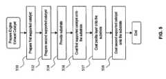
- FIG. 5is a flow diagram illustrating the steps for preparing an emission control catalyst according to another embodiment of the present invention.
- FIGS. 1A-1Dare schematic representations of different engine exhaust systems in which embodiments of the present invention may be used.
- the combustion process that occurs in an engine 102produces harmful pollutants, such as CO, various hydrocarbons, particulate matter, and nitrogen oxides (NOx), in an exhaust stream that is discharged through a tail pipe 108 of the exhaust system.
- harmful pollutantssuch as CO, various hydrocarbons, particulate matter, and nitrogen oxides (NOx)
- the exhaust stream from an engine 102passes through a catalytic converter 104 , before it is discharged into the atmosphere (environment) through a tail pipe 108 .
- the catalytic converter 104contains supported catalysts coated on a monolithic substrate that treat the exhaust stream from the engine 102 .
- the exhaust streamis treated by way of various catalytic reactions that occur within the catalytic converter 104 . These reactions include the oxidation of CO to form CO 2 , burning of hydrocarbons, and the conversion of NO to NO 2 .
- the exhaust stream from the engine 102passes through a catalytic converter 104 and a particulate filter 106 , before it is discharged into the atmosphere through a tail pipe 108 .
- the catalytic converter 104operates in the same manner as in the exhaust system of FIG. 1A .
- the particulate filter 106traps particulate matter that is in the exhaust stream, e.g., soot, liquid hydrocarbons, generally particulates in liquid form.
- the particulate filter 106includes a supported catalyst coated thereon for the oxidation of NO and/or to aid in combustion of particulate matter.
- the exhaust stream from the engine 102passes through a catalytic converter 104 , a pre-filter catalyst 105 and a particulate filter 106 , before it is discharged into the atmosphere through a tail pipe 108 .
- the catalytic converter 104operates in the same manner as in the exhaust system of FIG. 1A .
- the pre-filter catalyst 105includes a monolithic substrate and supported catalysts coated on the monolithic substrate for the oxidation of NO.
- the particulate filter 106traps particulate matter that is in the exhaust stream, e.g., soot, liquid hydrocarbons, generally particulates in liquid form.
- the exhaust streampasses from the engine 102 through a catalytic converter 104 , a particulate filter 106 , a selective catalytic reduction (SCR) unit 107 and an ammonia slip catalyst 110 , before it is discharged into the atmosphere through a tail pipe 108 .
- the catalytic converter 104operates in the same manner as in the exhaust system of FIG. 1A .
- the particulate filter 106traps particulate matter that is in the exhaust stream, e.g., soot, liquid hydrocarbons, generally particulates in liquid form.
- the particulate filter 106includes a supported catalyst coated thereon for the oxidation of NO and/or to aid in combustion of particulate matter.
- the SCR unit 107is provided to reduce the NOx species to N 2 .
- the SCR unit 107may be ammonia/urea based or hydrocarbon based.
- the ammonia slip catalyst 110is provided to reduce the amount of ammonia emissions through the tail pipe 108 .
- An alternative configurationplaces the SCR unit 107 in front of the particulate filter 106 .
- Alternative configurations of the exhaust systemincludes the provision of SCR unit 107 and the ammonia slip catalyst 110 in the exhaust system of FIG. 1A or 1 C, and the provision of just the SCR unit 107 , without the ammonia slip catalyst 110 , in the exhaust system of FIG. 1A , 1 B or 1 C.
- the regeneration of the particulate filtercan be either passive or active. Passive regeneration occurs automatically in the presence of NO 2 . Thus, as the exhaust stream containing NO 2 passes through the particulate filter, passive regeneration occurs. During regeneration, the particulates get oxidized and NO 2 gets converted back to NO. In general, higher amounts of NO 2 improve the regeneration performance, and thus this process is commonly referred to as NO 2 assisted oxidation. However, too much NO 2 is not desirable because excess NO 2 is released into the atmosphere and NO 2 is considered to be a more harmful pollutant than NO.
- the NO 2 used for regenerationcan be formed in the engine during combustion, from NO oxidation in the catalytic converter 104 , from NO oxidation in the pre-filter catalyst 105 , and/or from NO oxidation in a catalyzed version of the particulate filter 106 .
- Active regenerationis carried out by heating up the particulate filter 106 and oxidizing the particulates. At higher temperatures, NO 2 assistance of the particulate oxidation becomes less important.
- the heating of the particulate filter 106may be carried out in various ways known in the art. One way is to employ a fuel burner which heats the particulate filter 106 to particulate combustion temperatures. Another way is to increase the temperature of the exhaust stream by modifying the engine output when the particulate filter load reaches a pre-determined level.
- the present inventionprovides catalysts that are to be used in the catalytic converter 104 shown in FIGS. 1A-1D , or generally as catalysts in any vehicle emission control system, including as a diesel oxidation catalyst, a diesel filter catalyst, an ammonia-slip catalyst, an SCR catalyst, or as a component of a three-way catalyst.
- the present inventionfurther provides a vehicle emission control system, such as the ones shown in FIGS. 1A-1D , comprising an emission control catalyst comprising a monolith and a supported catalyst coated on the monolith.
- FIG. 2is an illustration of a catalytic converter with a cut-away section that shows a substrate 210 onto which supported metal catalysts are coated.
- the exploded view of the substrate 210shows that the substrate 210 has a honeycomb structure comprising a plurality of channels into which washcoats containing supported metal catalysts are flowed in slurry form so as to form coating 220 on the substrate 210 .
- FIGS. 3A-3Dillustrate different embodiments of the present invention.
- coating 220comprises two washcoat layers 221 , 223 on top of substrate 210 .
- Washcoat layer 221is the bottom layer that is disposed directly on top of the substrate 210 and contains metal particles having palladium and gold in close contact (also referred to as “palladium-gold metal particles”).
- Washcoat layer 223is the top layer that is in direct contact with the exhaust stream and contains metal particles having platinum alone or in close contact with another metal species such as palladium (also referred to as “platinum-containing metal particles”). Based on their positions relative to the exhaust stream, washcoat layer 223 encounters the exhaust stream before washcoat layer 221 .
- coating 220comprises three washcoat layers 221 , 222 , 223 on top of substrate 210 .
- Washcoat layer 221is the bottom layer that is disposed directly on top of the substrate 210 and includes palladium-gold metal particles.
- Washcoat layer 223is the top layer that is in direct contact with the exhaust stream and includes platinum-containing metal particles.
- Washcoat layer 222is the middle layer that is disposed in between washcoat layers 221 , 223 .
- the middle layeris provided to minimize the interaction between the Pt and Pd—Au components.
- the middle layermay be a blank support or may contain zeolites, rare earth oxides, or inorganic oxides. Based on their positions relative to the exhaust stream, washcoat layer 223 encounters the exhaust stream before washcoat layers 221 , 222 , and washcoat layer 222 encounters the exhaust stream before washcoat layer 221 .
- the substrate 210is a single monolith that has two coating zones 210 A, 210 B.
- a washcoat including platinum-containing metal particlesis coated onto a first zone 210 A and a washcoat including palladium-gold metal particles is coated onto a second zone 210 B.
- the substrate 210includes first and second monoliths 231 , 232 , which are physically separate monoliths.
- a washcoat including platinum-containing metal particlesis coated onto the first monolith 231 and a washcoat including palladium-gold metal particles is coated onto the second monolith 232 .
- All of the embodiments described aboveinclude a palladium-gold catalyst in combination with a platinum-based catalyst.
- the weight ratio of palladium to gold in the palladium-gold catalystis about 0.05:1 to 20:1, preferably from about 0.5:1 to about 2:1.
- the palladium-gold catalystmay be promoted with bismuth or other known promoters.
- the platinum-based catalystmay be a platinum catalyst, a platinum-palladium catalyst, a platinum catalyst promoted with bismuth or other now promoters, or other platinum-based catalysts (e.g., Pt—Rh, Pt—Ir, Pt—Ru, Pt—Au, Pt—Ag, Pt—Rh—Ir, Pt—Ir—Au, etc.).
- the preferred embodimentsemploy a platinum-palladium catalyst as the platinum-based catalyst.
- the weight ratio of platinum to palladium in this catalystis about 0.05:1 to 20:1, preferably from about 2:1 to about 4:1.
- the platinum-based catalystis situated so that it encounters the exhaust stream prior to the palladium-gold catalyst.
- the platinum-based catalystis included in the top layer 223 and the palladium-gold catalyst is included in the bottom layer 221 .
- the platinum-based catalystis included in the first zone 210 A and the palladium-gold catalyst is included in the second zone 210 B.
- the platinum-based catalystis included in the first monolith 231 and the palladium-gold catalyst is included in the second monolith 232 .
- a hydrocarbon absorbing materialis added to the emission control catalyst.
- the hydrocarbon absorbing materialis added to the emission control catalyst so that it encounters exhaust stream prior to the palladium-gold catalyst.
- the hydrocarbon absorbing materialmay be included in the top layer 223 .
- the hydrocarbon absorbing materialmay be included in the middle layer 222 or the top layer 223 . In the configuration shown in FIG.
- the hydrocarbon absorbing materialmay be included in the first zone 210 A.
- the hydrocarbon absorbing materialmay be included in the front monolith 231 .
- a hydrocarbon absorbing materialis zeolite. Zeolite may be a beta zeolite, ZSM-5 zeolite, and mixtures of the two, with or without other types of zeolites, in any weight ratio.
- any of the washcoat layers or zones, or monolithsmay include rare-earth oxides, such as cerium(IV) oxide (CeO 2 ) and ceria-zirconia (CeO 2 —ZrO 2 ).
- rare-earth oxidessuch as cerium(IV) oxide (CeO 2 ) and ceria-zirconia (CeO 2 —ZrO 2 ).
- FIG. 4is a flow diagram that illustrates the steps for preparing an emission control catalyst according to an embodiment of the present invention using the substrate 210 .
- a first supported catalyste.g., supported palladium-gold catalyst
- a second supported catalyste.g., supported platinum-based catalyst
- a monolithic substratesuch as substrate 210 shown in FIG. 2 (or monolithic substrates 231 , 232 shown in FIG. 3D ) is provided in step 414 .
- Exemplary monolithic substratesinclude those that are ceramic (e.g., cordierite), metallic, or silicon carbide based.
- the first supported catalyst in powder formare mixed in a solvent to form a washcoat slurry, and the washcoat slurry is coated as the bottom layer of the substrate 210 or onto a rear zone or rear monolith of the substrate 210 .
- the second supported catalyst in powder formare mixed in a solvent to form a washcoat slurry, and the washcoat slurry is coated as the top layer of the substrate 210 or onto a front zone or front monolith of the substrate 210 .
- zeolite or zeolite mixtureincluding one or more of beta zeolite, ZSM-5 zeolite, and other types of zeolites is added to the washcoat slurry before the washcoat slurry is coated in step 418 .
- step 516the first supported catalyst in powder form are mixed in a solvent to form a washcoat slurry, and the washcoat slurry is coated as the bottom layer of the substrate 210 .
- step 517zeolite or zeolite mixture is added to a solvent to form a washcoat slurry and this washcoat slurry is coated as the middle layer of the substrate 210 .
- step 518the second supported catalyst in powder form are mixed in a solvent to form a washcoat slurry, and the washcoat slurry is coated as the top layer of the substrate 210 .
- Tables 1 and 2 abovereflect the vehicle test performance for seven catalysts with equal precious group metal cost (assuming cost basis of Pt:Pd:Au of 4:1:2) that have been engine aged for 20 hours (with a two-mode cycle using fuel injection to get catalyst bed temperatures of about 650° C.).
- the CO and HC emissionswere measured from the tail pipe of a light-duty diesel vehicle (model year 2005) using bag data from the standard European MVEG test.
- Examples of Table 1were tested under low engine out temperatures (around 150° C. to 300° C.) and Examples of Table 2 were tested under high engine out temperatures (around 200° C. to 350° C.).
- catalystswere coated on a cordierite substrate with a diameter of 5.66 inches and length of 2.5 inches.
- Examples 4-7catalysts were coated on a pair of cordierite substrates, each with a diameter of 5.66 inches and length of 1.25 inches.
- Example 1represents a benchmark emission control catalyst and includes metal particles having platinum and palladium in close contact (also referred to as “platinum-palladium metal particles”) having a weight ratio of 2.8%:1.4% in the bottom layer and the top layer.
- the middle layercomprises beta zeolite.
- Example 2also represents a benchmark emission control catalyst and has the same composition as Example 1 except the middle layer comprises a zeolite mixture of beta zeolite and ZSM-5 zeolite at a weight ratio of 1:1.
- Example 3represents an emission control catalyst according to an embodiment of the present invention and includes palladium-gold metal particles having a weight ratio of 1.7%:2.0% in the bottom layer and platinum-palladium metal particles having a weight ratio of 3.0%:0.75% in the top layer.
- the middle layercomprises a zeolite mixture of beta zeolite and ZSM-5 zeolite at a weight ratio of 1:1. Relative to the benchmark emission control catalysts of Examples 1 and 2, a reduction in both HC and CO emissions has been observed with the emission control catalyst of Example 3.
- Example 4represents a benchmark emission control catalyst and includes platinum-palladium metal particles having a weight ratio of 2.0%:1.0% in the front brick and the rear brick.
- Examples 5, 6 and 7represent emission control catalysts according to embodiments of the present invention, each of which includes palladium-gold metal particles.
- Example 5includes platinum-palladium metal particles having a weight ratio of 2.0%:1.0% in the front brick and palladium-gold metal particles having weight ratio of 1.7%:2.0% in the rear brick.
- Example 6includes platinum-palladium metal particles having a weight ratio of 4.0%:1.0% in the front brick and palladium-gold metal particles having weight ratio of 1.7%:2.0% in the rear brick.
- Example 7includes platinum-palladium metal particles having a weight ratio of 2.0%:1.0% in the front brick and palladium-gold metal particles having weight ratio of 1.7%:2.0% in the rear brick. Both bricks in Example 7 used a washcoat slurry with approximately 28% ceria-zirconia added in (the rest was the precious group metal and alumina powder). Relative to the benchmark emission control catalyst of Example 4, a reduction in HC emissions and similar or better CO oxidation performance have been observed with the emission control catalysts of Examples 5, 6 and 7.
- Lanthanum-stabilized alumina(578 g, having a surface area of ⁇ 200 m 2 g ⁇ 1 ) and 2940 mL of de-ionized water (>18M ⁇ ) were added to a 5 L plastic beaker and magnetically stirred at about 500 rpm.
- the pH measuredwas 8.5 and the temperature measured was 25° C.
- Pd(NO 3 ) 2(67.8 g of 14.8% aqueous solution) was gradually added over a period of 10 min.
- the pH measuredwas 4.3.
- a second metal, HAuCl 424 g dissolved in 50 mL of de-ionized water
- the pHwas 4.0 and the temperature of the metal-support slurry was 25° C.
- the metal-support slurrywas stirred for an additional 30 min.
- NaBH 4 (29.4 g) and NaOH (31.1 g)were added to N 2 H 4 (142 mL of 35% aqueous solution) and stirred until the mixture became clear.
- This mixtureconstituted the reducing agent mixture.
- the metal-support slurry and reducing agent mixturewere combined continuously using two peristaltic pumps. The two streams were combined using a Y joint connected to a Vigreux column to cause turbulent mixing.
- the reaction product leaving the mixing chamber, i.e., the Vigreux columnwas pumped into an intermediate vessel of smaller volume and continuously stirred.
- the product in the intermediate vesselwas continuously pumped into a larger vessel, i.e., 5 L beaker, for residence and with continued stirring. The entire addition/mixing process lasted about 30 min.
- the resulting product slurrywas stirred in the larger vessel for an additional period of 1 h.
- the final pHwas 11.0 and the temperature was 25° C.
- the product slurrywas then filtered using vacuum techniques via Buchner funnels provided with a double layer of filter paper having 3 ⁇ m porosity.
- the filter cakewas then washed with about 20 L of de-ionized water in several approximately equal portions. Thereafter, the washed cake was dried at 110° C., ground to a fine powder using a mortar and pestle, and subsequently calcined at 500° C. for 2 h, with a heating rate of 8° C. min ⁇ 1 .
- This supported PdAu catalyst powder(1.7% Pd, 2.0% Au) was used in preparing Examples 3, 5, 6 and 7.
- Tri-layerPtPd (at 57.5 g/ft 3 ) 1st Layer, Beta Zeolite 2nd Layer, PtPd (at 57.5 g/ft 3 ) 3rd Layer
- the supported PtPd catalyst powder (2.8% Pt, 1.4% Pd) prepared as described abovewas made into a washcoat slurry via addition to de-ionized water, milling to an appropriate particle size (typically with a d 50 range from 3 to 7 ⁇ m), and pH adjustment to give an appropriate viscosity for washcoating.
- the washcoat slurrywas coated onto a round cordierite monolith (Corning, 400 cpsi, 5.66 inches ⁇ 2.5 inches), dried at 120° C. and calcined at 500° C. to give the first layer of the multi-layer coated monolith, such that the PtPd loading was ⁇ 57.5 g/ft 3 .
- beta zeolitewas made into a washcoat slurry via addition to de-ionized water, milling to an appropriate particle size (typically with a d 50 range from 3 to 7 ⁇ m), and pH adjustment to give an appropriate viscosity for washcoating.
- the zeolite washcoat slurrywas coated onto the cordierite monolith (with the first layer of PtPd), dried at 120° C. and calcined at 500° C. to give the second layer of the multi-layer coated monolith.
- the zeolite mixturecomprises about 20% of the total washcoat loading.
- the supported PtPd catalyst powder (2.8% Pt, 1.4% Pd) prepared as described abovewas made into a washcoat slurry via addition to de-ionized water, milling to an appropriate particle size (typically with a d 50 range from 3 to 7 ⁇ m), and pH adjustment to give an appropriate viscosity for washcoating.
- the washcoat slurrywas coated onto the cordierite monolith (with the first layer of PtPd and the second layer of zeolite), dried at 120° C. and calcined at 500° C. to give the third layer of the multi-layer coated monolith, such that the PtPd loading was ⁇ 57.5 g/ft 3 .
- the multi-layer coated monolithwas canned according to methods known in the art and tested using a certified testing facility on a light-duty diesel vehicle, as described above.
- Tri-layerPtPd (at 57.5 g/ft 3 ) 1st Layer, Zeolite Mixture 2nd Layer, PtPd (at 57.5 g/ft 3 ) 3rd Layer
- the supported PtPd catalyst powder (2.8% Pt, 1.4% Pd) prepared as described abovewas made into a washcoat slurry via addition to de-ionized water, milling to an appropriate particle size (typically with a d 50 range from 3 to 7 ⁇ m), and pH adjustment to give an appropriate viscosity for washcoating.
- the washcoat slurrywas coated onto a round cordierite monolith (Corning, 400 cpsi, 5.66 inches ⁇ 2.5 inches), dried at 120° C. and calcined at 500° C. to give the first layer of the multi-layer coated monolith, such that the PtPd loading was ⁇ 57.5 g/ft 3 .
- a beta zeolite and a ZSM-5 zeolitewere combined and made into a washcoat slurry via addition to de-ionized water, milling to an appropriate particle size (typically with a d 50 range from 3 to 7 ⁇ m), and pH adjustment to give an appropriate viscosity for washcoating.
- the zeolite washcoat slurrywas coated onto the cordierite monolith (with the first layer of PtPd), dried at 120° C. and calcined at 500° C. to give the second layer of the multi-layer coated monolith.
- the zeolite mixturecomprises about 20% of the total washcoat loading.
- the supported PtPd catalyst powder (2.8% Pt, 1.4% Pd) prepared as described abovewas made into a washcoat slurry via addition to de-ionized water, milling to an appropriate particle size (typically with a d 50 range from 3 to 7 ⁇ m), and pH adjustment to give an appropriate viscosity for washcoating.
- the washcoat slurrywas coated onto the cordierite monolith (with the first layer of PtPd and the second layer of zeolite), dried at 120° C. and calcined at 500° C. to give the third layer of the multi-layer coated monolith, such that the PtPd loading was ⁇ 57.5 g/ft 3 .
- the multi-layer coated monolithwas canned according to methods known in the art and tested using a certified testing facility on a light-duty diesel vehicle, as described above.
- the supported PdAu catalyst powder (1.7% Pd, 2.0% Au) prepared as described abovewas made into a washcoat slurry via addition to de-ionized water, milling to an appropriate particle size (typically with a d 50 range from 3 to 7 ⁇ m), and pH adjustment to give an appropriate viscosity for washcoating.
- the washcoat slurrywas coated onto a round cordierite monolith (Corning, 400 cpsi, 5.66 inches ⁇ 2.5 inches), dried at 120° C. and calcined at 500° C. to give the first layer of the multi-layer coated monolith, such that the PdAu loading was ⁇ 65 g/ft 3 .
- a beta zeolite and a ZSM-5 zeolitewere combined and made into a washcoat slurry via addition to de-ionized water, milling to an appropriate particle size (typically with a d 50 range from 3 to 7 ⁇ m), and pH adjustment to give an appropriate viscosity for washcoating.
- the zeolite washcoat slurrywas coated onto the cordierite monolith (with the first layer of PtPd), dried at 120° C. and calcined at 500° C. to give the second layer of the multi-layer coated monolith.
- the zeolite mixturecomprises about 20% of the total washcoat loading.
- the supported PtPd catalyst powder (3.0% Pt, 0.75% Pd) prepared as described abovewas made into a washcoat slurry via addition to de-ionized water, milling to an appropriate particle size (typically with a d 50 range from 3 to 7 ⁇ m), and pH adjustment to give an appropriate viscosity for washcoating.
- the washcoat slurrywas coated onto the cordierite monolith (with the first layer of PdAu and the second layer of zeolite), dried at 120° C. and calcined at 500° C. to give the third layer of the multi-layer coated monolith, such that the PtPd loading was ⁇ 65 g/ft 3 .
- the multi-layer coated monolithwas canned according to methods known in the art and tested using a certified testing facility on a light-duty diesel vehicle, as described above.
- the supported PtPd catalyst powder (2.0% Pt, 1.0% Pd) prepared abovewas made into a washcoat slurry via addition to de-ionized water, milling to an appropriate particle size (typically with a d 50 range from 3 to 7 ⁇ m), and pH adjustment to give an appropriate viscosity for washcoating.
- the washcoat slurrywas coated onto both the front brick and the rear brick of a round cordierite monolith (each brick: Corning, 400 cpsi, 5.66 inches ⁇ 1.25 inches), dried at 120° C. and calcined at 500° C. to give the final coated monolith with a precious metal (Pt+Pd) loading of 120 g/ft 3 .
- the coated monolithwas canned according to methods known in the art and tested using a certified testing facility on a light-duty diesel vehicle, as described above.
- the supported PtPd catalyst powder (2.0% Pt, 1.0% Pd) prepared as described abovewas made into a washcoat slurry via addition to de-ionized water, milling to an appropriate particle size (typically with a d 50 range from 3 to 7 ⁇ m), and pH adjustment to give an appropriate viscosity for washcoating.
- the washcoat slurrywas coated onto a round cordierite monolith (Corning, 400 cpsi, 5.66 inches ⁇ 1.25 inches), dried at 120° C. and calcined at 500° C. to give the final coated monolith with a precious metal loading of 120 g/ft 3 PtPd. This represented the front brick of a two brick system.
- the supported PdAu catalyst powder (1.7% Pd, 2.0% Au) prepared as described abovewas made into a washcoat slurry via addition to de-ionized water, milling to an appropriate particle size (typically with a d 50 range from 3 to 7 ⁇ m), and pH adjustment to give an appropriate viscosity for washcoating.
- the washcoat slurrywas coated onto a round cordierite monolith (Corning, 400 cpsi, 5.66 inches ⁇ 1.25 inches), dried at 120° C. and calcined at 500° C. to give the final coated monolith with a precious metal loading of 175 g/ft 3 PdAu. This represented the outlet brick of a two brick system.
- coated PtPd monolithfront brick
- coated PdAu monolithrear brick
- the supported PtPd catalyst powder (3.0% Pt, 0.75% Pd) prepared as described abovewas made into a washcoat slurry via addition to de-ionized water, milling to an appropriate particle size (typically with a d 50 range from 3 to 7 ⁇ m), and pH adjustment to give an appropriate viscosity for washcoating.
- the washcoat slurrywas coated onto a round cordierite monolith (Corning, 400 cpsi, 5.66 inches ⁇ 1.25 inches), dried at 120° C. and calcined at 500° C. to give the final coated monolith with a precious metal loading of 130 g/ft 3 PtPd. This represented the front brick of a two brick system.
- the supported PdAu catalyst powder (1.7% Pd, 2.0% Au) prepared as described abovewas made into a washcoat slurry via addition to de-ionized water, milling to an appropriate particle size (typically with a d 50 range from 3 to 7 ⁇ m), and pH adjustment to give an appropriate viscosity for washcoating.
- the washcoat slurrywas coated onto a round cordierite monolith (Corning, 400 cpsi, 5.66 inches ⁇ 1.25 inches), dried at 120° C. and calcined at 500° C. to give the final coated monolith with a precious metal loading of 130 g/ft 3 PdAu. This represented the outlet brick of a two brick system.
- coated PtPd monolithfront brick
- coated PdAu monolithrear brick
- the supported PtPd catalyst powder (2.0% Pt, 1.0% Pd) prepared as described abovewas made into a washcoat slurry via addition to de-ionized water, milling to an appropriate particle size (typically with a d 50 range from 3 to 7 ⁇ m), and pH adjustment to give an appropriate viscosity for washcoating.
- Ceria-zirconiawas added to this washcoat slurry so that ceria-zirconia represented about 28% by weight.
- the washcoat slurrywas coated onto a round cordierite monolith (Corning, 400 cpsi, 5.66 inches ⁇ 1.25 inches), dried at 120° C. and calcined at 500° C. to give the final coated monolith with a precious metal loading of 150 g/ft 3 PtPd. This represented the front brick of a two brick system.
- the supported PdAu catalyst powder (1.7% Pd, 2.0% Au) prepared as described abovewas made into a washcoat slurry via addition to de-ionized water, milling to an appropriate particle size (typically with a d 50 range from 3 to 7 ⁇ m), and pH adjustment to give an appropriate viscosity for washcoating.
- Ceria-zirconiawas added to this washcoat slurry so that ceria-zirconia represented about 28% by weight.
- the washcoat slurrywas coated onto a round cordierite monolith (Corning, 400 cpsi, 5.66 inches ⁇ 1.25 inches), dried at 120° C. and calcined at 500° C. to give the final coated monolith with a precious metal loading of 130 g/ft 3 PdAu. This represented the outlet brick of a two brick system.
- coated PtPd monolithfront brick
- coated PdAu monolithrear brick
Landscapes
- Chemical & Material Sciences (AREA)
- Engineering & Computer Science (AREA)
- Materials Engineering (AREA)
- Chemical Kinetics & Catalysis (AREA)
- Combustion & Propulsion (AREA)
- Organic Chemistry (AREA)
- General Engineering & Computer Science (AREA)
- Mechanical Engineering (AREA)
- Health & Medical Sciences (AREA)
- Toxicology (AREA)
- Biomedical Technology (AREA)
- Environmental & Geological Engineering (AREA)
- Analytical Chemistry (AREA)
- General Chemical & Material Sciences (AREA)
- Oil, Petroleum & Natural Gas (AREA)
- Catalysts (AREA)
- Exhaust Gas Treatment By Means Of Catalyst (AREA)
Abstract
Description
| TABLE 1 | |||||
| CO | HC | ||||
| emissions | emissions | ||||
| Example | Bottom Layer | Middle Layer | Top Layer | (g/km) | (g/km) |
| 1 | PtPd (2.8%:1.4% | Beta zeolite at | PtPd (2.8%:1.4% | 0.366 | 0.079 |
| by weight) at 57.5 g/ft3 | 0.5 g/in3 | by weight) at 57.5 g/ft3 | |||
| 2 | PtPd (2.8%:1.4% | Beta zeolite and | PtPd (2.8%:1.4% | 0.332 | 0.066 |
| by weight) at 57.5 g/ft3 | ZSM-5 zeolite | by weight) at 57.5 g/ft3 | |||
| (1:1 by weight) | |||||
| 3 | PdAu (1.7%:2.0% | Beta zeolite and | PtPd (3.0%:0.75% | 0.296 | 0.049 |
| Test A | by weight) at 65 g/ft3 | ZSM-5 zeolite | by weight) at 65.0 g/ft3 | ||
| (1:1 by weight) | |||||
| 3 | PdAu (1.7%:2.0% | Beta zeolite and | PtPd (3.0%:0.75% | 0.296 | 0.057 |
| Test B | by weight) at 65 g/ft3 | ZSM-5 zeolite | by weight) at 65.0 g/ft3 | ||
| (1:1 by weight) | |||||
| TABLE 2 | ||||
| CO emissions | HC emissions | |||
| Example | Front Brick | Rear Brick | (g/km) | (g/km) |
| 4 | PtPd (2.0%:1.0% by | PtPd (2.0%:1.0% by | 0.143 | 0.0539 |
| weight) at 120 g/ft3 | weight) at 120 g/ft3 | |||
| 5 | PtPd (2.0%:1.0% by | PdAu (1.7%:2.0% by | 0.146 | 0.0474 |
| weight) at 120 g/ft3 | weight) at 175 g/ft3 | |||
| 6 | PtPd (3.0%:0.75% by | PdAu (1.7%:2.0% by | 0.121 | 0.0505 |
| weight) at 130 g/ft3 | weight) at 130 g/ft3 | |||
| 7 | PtPd (2.0%:1.0% by | PdAu (1.7%:2.0% by | 0.123 | 0.0385 |
| weight) at 150 g/ft3 | weight) at 130 g/ft3 | |||
Claims (20)
Priority Applications (2)
| Application Number | Priority Date | Filing Date | Title |
|---|---|---|---|
| US12/436,028US7745367B2 (en) | 2006-11-27 | 2009-05-05 | Engine exhaust catalysts containing palladium-gold |
| US12/615,135US8258070B2 (en) | 2006-11-27 | 2009-11-09 | Engine exhaust catalysts containing palladium-gold |
Applications Claiming Priority (3)
| Application Number | Priority Date | Filing Date | Title |
|---|---|---|---|
| US86733506P | 2006-11-27 | 2006-11-27 | |
| US11/942,710US7534738B2 (en) | 2006-11-27 | 2007-11-20 | Engine exhaust catalysts containing palladium-gold |
| US12/436,028US7745367B2 (en) | 2006-11-27 | 2009-05-05 | Engine exhaust catalysts containing palladium-gold |
Related Parent Applications (1)
| Application Number | Title | Priority Date | Filing Date |
|---|---|---|---|
| US11/942,710ContinuationUS7534738B2 (en) | 2006-11-27 | 2007-11-20 | Engine exhaust catalysts containing palladium-gold |
Related Child Applications (1)
| Application Number | Title | Priority Date | Filing Date |
|---|---|---|---|
| US12/615,135Continuation-In-PartUS8258070B2 (en) | 2006-11-27 | 2009-11-09 | Engine exhaust catalysts containing palladium-gold |
Publications (2)
| Publication Number | Publication Date |
|---|---|
| US20090214396A1 US20090214396A1 (en) | 2009-08-27 |
| US7745367B2true US7745367B2 (en) | 2010-06-29 |
Family
ID=39637671
Family Applications (2)
| Application Number | Title | Priority Date | Filing Date |
|---|---|---|---|
| US11/942,710ActiveUS7534738B2 (en) | 2006-11-27 | 2007-11-20 | Engine exhaust catalysts containing palladium-gold |
| US12/436,028ActiveUS7745367B2 (en) | 2006-11-27 | 2009-05-05 | Engine exhaust catalysts containing palladium-gold |
Family Applications Before (1)
| Application Number | Title | Priority Date | Filing Date |
|---|---|---|---|
| US11/942,710ActiveUS7534738B2 (en) | 2006-11-27 | 2007-11-20 | Engine exhaust catalysts containing palladium-gold |
Country Status (1)
| Country | Link |
|---|---|
| US (2) | US7534738B2 (en) |
Cited By (31)
| Publication number | Priority date | Publication date | Assignee | Title |
|---|---|---|---|---|
| US20090193796A1 (en)* | 2008-02-05 | 2009-08-06 | Basf Catalysts Llc | Gasoline engine emissions treatment systems having particulate traps |
| US20090274903A1 (en)* | 2008-04-30 | 2009-11-05 | William Peter Addiego | Catalysts On Substrates And Methods For Providing The Same |
| US20110143933A1 (en)* | 2009-12-15 | 2011-06-16 | SDCmaterials, Inc. | Advanced catalysts for automotive applications |
| US20110173959A1 (en)* | 2008-05-09 | 2011-07-21 | Johnson Matthey Public Limited Company | Exhaust system for lean-burn internal combustion engine comprising pd-au-alloy catalyst |
| US20110206584A1 (en)* | 2010-02-23 | 2011-08-25 | Ford Global Technologies, Llc | Palladium-contaning oxidation catalyst |
| US20110251055A1 (en)* | 2010-04-13 | 2011-10-13 | Millennium Inorganic Chemicals, Inc. | Supported Precious Metal Catalysts Via Hydrothermal Deposition |
| US8492306B2 (en) | 2011-10-04 | 2013-07-23 | GM Global Technology Operations LLC | Method and apparatus for preparing a catalyst |
| US20130287660A1 (en)* | 2010-11-22 | 2013-10-31 | Umicore Ag & Co. Kg | Three-way catalyst having an upstream single-layer catalyst |
| US8604398B1 (en) | 2007-05-11 | 2013-12-10 | SDCmaterials, Inc. | Microwave purification process |
| US20140044627A1 (en)* | 2009-08-05 | 2014-02-13 | Basf Corporation | Preparation of Diesel Oxidation Catalyst Via Deposition of Colloidal Nanoparticles |
| US8652992B2 (en) | 2009-12-15 | 2014-02-18 | SDCmaterials, Inc. | Pinning and affixing nano-active material |
| US8669202B2 (en) | 2011-02-23 | 2014-03-11 | SDCmaterials, Inc. | Wet chemical and plasma methods of forming stable PtPd catalysts |
| US8668803B1 (en) | 2009-12-15 | 2014-03-11 | SDCmaterials, Inc. | Sandwich of impact resistant material |
| US8679433B2 (en) | 2011-08-19 | 2014-03-25 | SDCmaterials, Inc. | Coated substrates for use in catalysis and catalytic converters and methods of coating substrates with washcoat compositions |
| US8759248B2 (en) | 2007-10-15 | 2014-06-24 | SDCmaterials, Inc. | Method and system for forming plug and play metal catalysts |
| US8803025B2 (en) | 2009-12-15 | 2014-08-12 | SDCmaterials, Inc. | Non-plugging D.C. plasma gun |
| US8815189B2 (en) | 2010-04-19 | 2014-08-26 | Basf Corporation | Gasoline engine emissions treatment systems having particulate filters |
| US8865611B2 (en) | 2009-12-15 | 2014-10-21 | SDCmaterials, Inc. | Method of forming a catalyst with inhibited mobility of nano-active material |
| US20150071839A1 (en)* | 2012-03-17 | 2015-03-12 | Daimler Ag | Catalyst Component of a Motor Vehicle Exhaust Gas Cleaning System and Use of a Catalyst Component |
| US9034269B2 (en)* | 2012-11-29 | 2015-05-19 | Basf Se | Diesel oxidation catalyst comprising palladium, gold and ceria |
| US9149797B2 (en) | 2009-12-15 | 2015-10-06 | SDCmaterials, Inc. | Catalyst production method and system |
| US9156025B2 (en) | 2012-11-21 | 2015-10-13 | SDCmaterials, Inc. | Three-way catalytic converter using nanoparticles |
| US20160167022A1 (en)* | 2013-05-17 | 2016-06-16 | Johnson Matthey Public Limited Company | Oxidation Catalyst for a Compression Ignition Engine |
| US9427732B2 (en) | 2013-10-22 | 2016-08-30 | SDCmaterials, Inc. | Catalyst design for heavy-duty diesel combustion engines |
| US9511352B2 (en) | 2012-11-21 | 2016-12-06 | SDCmaterials, Inc. | Three-way catalytic converter using nanoparticles |
| US9517448B2 (en) | 2013-10-22 | 2016-12-13 | SDCmaterials, Inc. | Compositions of lean NOx trap (LNT) systems and methods of making and using same |
| US9586179B2 (en) | 2013-07-25 | 2017-03-07 | SDCmaterials, Inc. | Washcoats and coated substrates for catalytic converters and methods of making and using same |
| US9662636B2 (en) | 2014-04-17 | 2017-05-30 | Basf Corporation | Zoned catalyst composites |
| US9687811B2 (en) | 2014-03-21 | 2017-06-27 | SDCmaterials, Inc. | Compositions for passive NOx adsorption (PNA) systems and methods of making and using same |
| US11161098B2 (en)* | 2018-05-18 | 2021-11-02 | Umicore Ag & Co. Kg | Three-way catalyst |
| US20230294077A1 (en)* | 2022-03-15 | 2023-09-21 | Toyota Jidosha Kabushiki Kaisha | Method of producing catalyst for exhaust gas purification |
Families Citing this family (44)
| Publication number | Priority date | Publication date | Assignee | Title |
|---|---|---|---|---|
| US20050195966A1 (en)* | 2004-03-03 | 2005-09-08 | Sigma Dynamics, Inc. | Method and apparatus for optimizing the results produced by a prediction model |
| KR100667028B1 (en)* | 2005-10-04 | 2007-01-10 | 희성엥겔하드주식회사 | Reductionless injection SCR catalytic converter |
| US7749472B2 (en)* | 2006-08-14 | 2010-07-06 | Basf Corporation | Phosgard, a new way to improve poison resistance in three-way catalyst applications |
| US8258070B2 (en)* | 2006-11-27 | 2012-09-04 | WGCH Technology Limited | Engine exhaust catalysts containing palladium-gold |
| JP4849035B2 (en)* | 2007-08-08 | 2011-12-28 | マツダ株式会社 | Particulate filter with catalyst |
| US9993771B2 (en)* | 2007-12-12 | 2018-06-12 | Basf Corporation | Emission treatment catalysts, systems and methods |
| US9863297B2 (en)* | 2007-12-12 | 2018-01-09 | Basf Corporation | Emission treatment system |
| US7832200B2 (en)* | 2008-04-23 | 2010-11-16 | Caterpillar Inc | Exhaust system implementing feedforward and feedback control |
| US8211392B2 (en) | 2009-01-16 | 2012-07-03 | Basf Corporation | Diesel oxidation catalyst composite with layer structure for carbon monoxide and hydrocarbon conversion |
| US8329607B2 (en)* | 2009-01-16 | 2012-12-11 | Basf Corporation | Layered diesel oxidation catalyst composites |
| DE102009006403A1 (en)* | 2009-01-28 | 2010-08-05 | Süd-Chemie AG | Vanadium-free diesel oxidation catalyst and process for its preparation |
| US8637426B2 (en) | 2009-04-08 | 2014-01-28 | Basf Corporation | Zoned catalysts for diesel applications |
| US8545652B1 (en) | 2009-12-15 | 2013-10-01 | SDCmaterials, Inc. | Impact resistant material |
| US20110143930A1 (en)* | 2009-12-15 | 2011-06-16 | SDCmaterials, Inc. | Tunable size of nano-active material on nano-support |
| US8470112B1 (en) | 2009-12-15 | 2013-06-25 | SDCmaterials, Inc. | Workflow for novel composite materials |
| US20120302439A1 (en)* | 2009-12-31 | 2012-11-29 | Nanostellar, Inc. | Engine exhaust catalysts doped with bismuth or manganese |
| US9370769B2 (en) | 2010-10-26 | 2016-06-21 | Umicore Ag & Co. Kg | Diesel oxidation catalyst |
| GB201110850D0 (en) | 2011-03-04 | 2011-08-10 | Johnson Matthey Plc | Catalyst and mehtod of preparation |
| JP5938819B2 (en) | 2011-10-06 | 2016-06-22 | ジョンソン、マッセイ、パブリック、リミテッド、カンパニーJohnson Matthey Public Limited Company | Oxidation catalyst for exhaust gas treatment |
| GB201200781D0 (en)* | 2011-12-12 | 2012-02-29 | Johnson Matthey Plc | Exhaust system for a lean-burn ic engine comprising a pgm component and a scr catalyst |
| GB201200783D0 (en) | 2011-12-12 | 2012-02-29 | Johnson Matthey Plc | Substrate monolith comprising SCR catalyst |
| GB2497597A (en) | 2011-12-12 | 2013-06-19 | Johnson Matthey Plc | A Catalysed Substrate Monolith with Two Wash-Coats |
| GB201200784D0 (en) | 2011-12-12 | 2012-02-29 | Johnson Matthey Plc | Exhaust system for a lean-burn internal combustion engine including SCR catalyst |
| GB201210891D0 (en)* | 2012-06-19 | 2012-08-01 | Johnson Matthey Plc | Catalyst composition |
| GB201220912D0 (en)* | 2012-11-21 | 2013-01-02 | Johnson Matthey Plc | Oxidation catalyst for treating the exhaust gas of a compression ignition engine |
| CN104797334A (en)* | 2012-12-06 | 2015-07-22 | 优美科股份公司及两合公司 | Zoned diesel oxidation catalyst |
| KR101427933B1 (en) | 2012-12-28 | 2014-08-11 | 현대자동차 주식회사 | Catalytic converter of internal combustion engine and apparatus of purifying exhaust gas provided with the same |
| US9227177B2 (en) | 2013-03-15 | 2016-01-05 | Clean Diesel Technologies, Inc. | Coating process of Zero-PGM catalysts and methods thereof |
| US9216383B2 (en) | 2013-03-15 | 2015-12-22 | Clean Diesel Technologies, Inc. | System and method for two and three way ZPGM catalyst |
| US9511350B2 (en) | 2013-05-10 | 2016-12-06 | Clean Diesel Technologies, Inc. (Cdti) | ZPGM Diesel Oxidation Catalysts and methods of making and using same |
| US9511355B2 (en) | 2013-11-26 | 2016-12-06 | Clean Diesel Technologies, Inc. (Cdti) | System and methods for using synergized PGM as a three-way catalyst |
| US9259716B2 (en) | 2013-03-15 | 2016-02-16 | Clean Diesel Technologies, Inc. | Oxidation catalyst systems compositions and methods thereof |
| US20140274662A1 (en) | 2013-03-15 | 2014-09-18 | Cdti | Systems and Methods for Variations of ZPGM Oxidation Catalysts Compositions |
| US9073011B2 (en)* | 2013-04-04 | 2015-07-07 | Randal Hatfield | Systems and methods for diesel oxidation catalyst with decreased SO3 emissions |
| JP5676679B2 (en)* | 2013-04-19 | 2015-02-25 | 株式会社キャタラー | Exhaust gas purification catalyst |
| US9545626B2 (en) | 2013-07-12 | 2017-01-17 | Clean Diesel Technologies, Inc. | Optimization of Zero-PGM washcoat and overcoat loadings on metallic substrate |
| GB2518418A (en)* | 2013-09-20 | 2015-03-25 | Johnson Matthey Plc | Electrically heated catalyst for a compression ignition engine |
| JP2016531725A (en)* | 2013-09-23 | 2016-10-13 | エスディーシーマテリアルズ, インコーポレイテッド | High surface area catalyst |
| US8853121B1 (en) | 2013-10-16 | 2014-10-07 | Clean Diesel Technology Inc. | Thermally stable compositions of OSM free of rare earth metals |
| US9511358B2 (en) | 2013-11-26 | 2016-12-06 | Clean Diesel Technologies, Inc. | Spinel compositions and applications thereof |
| WO2015111079A1 (en) | 2014-01-21 | 2015-07-30 | Council Of Scientific & Industrial Research | Non noble metal based diesel oxidation catalyst |
| JP6545962B2 (en)* | 2015-01-22 | 2019-07-17 | 株式会社キャタラー | Exhaust gas purification catalyst |
| GB2535327B (en)* | 2015-02-13 | 2017-08-16 | Johnson Matthey Plc | Exhaust system for a compression ignition engine having a capture region for volatilised platinum |
| GB2535466A (en) | 2015-02-16 | 2016-08-24 | Johnson Matthey Plc | Catalyst with stable nitric oxide (NO) oxidation performance |
Citations (52)
| Publication number | Priority date | Publication date | Assignee | Title |
|---|---|---|---|---|
| US3929965A (en) | 1974-05-16 | 1975-12-30 | Grace W R & Co | Dual purpose auto exhaust catalysts |
| US4048096A (en) | 1976-04-12 | 1977-09-13 | E. I. Du Pont De Nemours And Company | Surface impregnated catalyst |
| US4053434A (en) | 1976-06-19 | 1977-10-11 | Union Oil Company Of California | Exhaust gas conversion catalyst |
| US4136062A (en) | 1977-10-17 | 1979-01-23 | The Board Of Trustees Of Leland Stanford Junior University | Highly active pd-au catalyst |
| US4369132A (en) | 1980-01-18 | 1983-01-18 | Toyota Jidosha Kogyo Kabushiki Kaisha | Exhaust gas purifying catalyst |
| US4490481A (en) | 1982-03-15 | 1984-12-25 | Ste Francaise Des Produits Pour Catalyse Chez Institut Francais Du Petrole | Supported palladium-gold catalyst, and its manufacture |
| US4499301A (en) | 1979-04-20 | 1985-02-12 | National Distillers And Chemical Corporation | Process for the preparation of unsaturated aldehydes and carboxylic acids |
| US4552860A (en) | 1982-05-14 | 1985-11-12 | National Distillers And Chemical Corporation | Catalyst for the preparation of unsaturated aldehydes and carboxylic acids |
| US4931419A (en) | 1987-10-21 | 1990-06-05 | Pro-Catalyse | Catalyst for the conversion of vehicular exhaust gases and process for preparing the catalyst |
| EP0449423A1 (en) | 1990-02-26 | 1991-10-02 | Nippon Shokubai Co., Ltd. | Catalyst for purification of exhaust gas from diesel engine |
| US5185308A (en) | 1991-05-06 | 1993-02-09 | Bp Chemicals Limited | Catalysts and processes for the manufacture of vinyl acetate |
| US5194417A (en) | 1991-12-05 | 1993-03-16 | Quantum Chemical Corporation | Pretreatment of palladium-gold catalysts useful in vinyl acetate synthesis |
| US5258340A (en) | 1991-02-15 | 1993-11-02 | Philip Morris Incorporated | Mixed transition metal oxide catalysts for conversion of carbon monoxide and method for producing the catalysts |
| EP0707883A2 (en) | 1994-10-06 | 1996-04-24 | N.E. Chemcat Corporation | Catalyst and method for purifying exhaust gases |
| WO1997000119A1 (en) | 1995-06-15 | 1997-01-03 | Engelhard Corporation | Diesel engine exhaust gas catalyst and method of use |
| US5665668A (en) | 1994-01-25 | 1997-09-09 | Grigorova; Bojidara | Method of making a catalyst |
| JPH09299763A (en) | 1996-05-15 | 1997-11-25 | Sumitomo Metal Mining Co Ltd | Denitration catalyst layer and denitration method |
| US5693586A (en) | 1996-06-28 | 1997-12-02 | Hoechst Celanese Corporation | Palladium-gold catalyst for vinyl acetate production |
| US5700753A (en) | 1996-05-24 | 1997-12-23 | Hoechst Celanese Corporation | Heterogeneous bimetallic palladium-gold catalyst for vinyl acetate production |
| US5702675A (en) | 1994-12-16 | 1997-12-30 | Toyota Jidosha Kabushiki Kaisha | Catalyst for purifying exhaust gases and process for producing the same |
| US5848356A (en) | 1995-10-02 | 1998-12-08 | Motorola, Inc. | Method for implementing icons in a radio communication device |
| US5849256A (en) | 1996-04-26 | 1998-12-15 | Engelhard Corporation | Method for oxidizing carbon monoxide in a gas stream containing oxidizable sulphur compounds |
| US5894068A (en) | 1992-12-14 | 1999-04-13 | Kharas; Karl C. C. | Reduction of NOx in the exhaust gases from internal combustion engines containing excess oxygen |
| US5911961A (en) | 1994-12-06 | 1999-06-15 | Ict Co., Ltd. | Catalyst for purification of diesel engine exhaust gas |
| US5948377A (en) | 1996-09-04 | 1999-09-07 | Engelhard Corporation | Catalyst composition |
| US5977012A (en) | 1994-06-01 | 1999-11-02 | Asec Manufacturing General Partnership | Alloyed metal catalysts for the reduction of NOx in the exhaust gases from internal combustion engines containing excess oxygen |
| US5989507A (en) | 1996-09-04 | 1999-11-23 | Engelhard Corporation | Catalyst composition |
| US6022823A (en) | 1995-11-07 | 2000-02-08 | Millennium Petrochemicals, Inc. | Process for the production of supported palladium-gold catalysts |
| US6034030A (en) | 1994-02-22 | 2000-03-07 | Celanese International Corporation | Vinyl acetate catalyst preparation method |
| US6087298A (en) | 1996-05-14 | 2000-07-11 | Engelhard Corporation | Exhaust gas treatment system |
| US6093378A (en) | 1997-05-07 | 2000-07-25 | Engelhard Corporation | Four-way diesel exhaust catalyst and method of use |
| US6147027A (en) | 1997-09-24 | 2000-11-14 | Toyota Jidosha Kabushiki Kaisha | Alloy catalyst and process for producing the same |
| US6156927A (en) | 1998-02-05 | 2000-12-05 | Engelhard Corporation | Suppression of aging for Pd-Au vinyl acetate monomer catalyst |
| US6235255B1 (en) | 1999-05-21 | 2001-05-22 | Asec Manufacturing | Catalyst support having zeolite with high sodium back ion-exchange capacity and catalysts made therefrom |
| US20010038812A1 (en) | 1992-11-19 | 2001-11-08 | Yavuz Bulent O. | Zeolite-containing oxidation catalyst and method of use |
| US20010053340A1 (en) | 1994-07-05 | 2001-12-20 | Ngk Insulators Ltd | Catalyst-adsorbent for purification of exhaust gases and method for purification of exhaust gases |
| US6420308B1 (en) | 2000-07-07 | 2002-07-16 | Saudi Basic Industries Corp | Highly selective shell impregnated catalyst of improved space time yield for production of vinyl acetate |
| US20030108465A1 (en) | 1999-07-02 | 2003-06-12 | Engelhard Corporation | Diesel oxidation catalyst |
| US6656873B2 (en) | 2001-06-14 | 2003-12-02 | Sanjay Chaturvedi | Mixed metal oxide catalyst |
| US6685900B2 (en) | 2000-03-01 | 2004-02-03 | Dmc2 Degussa Metals Catalysts Cerdec Ag | Catalyst for purifying the exhaust gases of diesel engines, and process for the preparation thereof |
| US6727097B2 (en) | 2000-06-15 | 2004-04-27 | Engelhard Corporation | Method and apparatus for accelerated catalyst poisoning and deactivation |
| US6740615B2 (en) | 2000-12-22 | 2004-05-25 | Hydrocarbon Technologies, Inc. | Regeneration of used supported noble metal catalysts |
| US6763309B2 (en) | 2001-08-06 | 2004-07-13 | Novodynamics, Inc. | Method and system for the development of materials |
| US6794332B2 (en) | 2000-07-07 | 2004-09-21 | Saudi Basic Industries Corporation | Highly selective shell impregnated catalyst of improved space time yield for production of vinyl acetate |
| US6821501B2 (en) | 2001-03-05 | 2004-11-23 | Shell Oil Company | Integrated flameless distributed combustion/steam reforming membrane reactor for hydrogen production and use thereof in zero emissions hybrid power system |
| WO2005030382A2 (en) | 2003-09-26 | 2005-04-07 | 3M Innovative Properties Company | Nanoscale gold catalysts, activating agents, support media, and related methodologies useful for making such catalyst systems especially when the gold is deposited onto the support media using physical vapor deposition |
| US20050169807A1 (en) | 2004-02-04 | 2005-08-04 | The Research Foundation Of State University Of New York | Methods for forming palladium alloy thin films and optical hydrogen sensors employing palladium alloy thin films |
| EP1570895A2 (en) | 2004-03-05 | 2005-09-07 | Delphi Technologies, Inc. | Exhaust gas treatment system and catalyst system |
| US6944202B2 (en) | 1999-05-04 | 2005-09-13 | Neokismet, L.L.C. | Surface catalyst infra red laser |
| US20050261125A1 (en) | 2004-05-24 | 2005-11-24 | Tanaka Kikinzoku Kogyo K.K. | Catalyst and process for preparing the same |
| US20060088459A1 (en) | 2004-10-25 | 2006-04-27 | United States Of America As Represented By The Administrator Of The Nasa | Catalyst for treatment and control of post-combustion emissions |
| WO2007001075A1 (en) | 2005-06-29 | 2007-01-04 | N-Crypt, Inc. | Encryption device, encryption method, decryption device, decryption method, and data structure |
Family Cites Families (1)
| Publication number | Priority date | Publication date | Assignee | Title |
|---|---|---|---|---|
| US136062A (en)* | 1873-02-18 | Improvement in gang-plows |
- 2007
- 2007-11-20USUS11/942,710patent/US7534738B2/enactiveActive
- 2009
- 2009-05-05USUS12/436,028patent/US7745367B2/enactiveActive
Patent Citations (58)
| Publication number | Priority date | Publication date | Assignee | Title |
|---|---|---|---|---|
| US3929965A (en) | 1974-05-16 | 1975-12-30 | Grace W R & Co | Dual purpose auto exhaust catalysts |
| US4048096A (en) | 1976-04-12 | 1977-09-13 | E. I. Du Pont De Nemours And Company | Surface impregnated catalyst |
| US4053434A (en) | 1976-06-19 | 1977-10-11 | Union Oil Company Of California | Exhaust gas conversion catalyst |
| US4136062A (en) | 1977-10-17 | 1979-01-23 | The Board Of Trustees Of Leland Stanford Junior University | Highly active pd-au catalyst |
| US4499301A (en) | 1979-04-20 | 1985-02-12 | National Distillers And Chemical Corporation | Process for the preparation of unsaturated aldehydes and carboxylic acids |
| US4369132A (en) | 1980-01-18 | 1983-01-18 | Toyota Jidosha Kogyo Kabushiki Kaisha | Exhaust gas purifying catalyst |
| US4490481A (en) | 1982-03-15 | 1984-12-25 | Ste Francaise Des Produits Pour Catalyse Chez Institut Francais Du Petrole | Supported palladium-gold catalyst, and its manufacture |
| US4533779A (en) | 1982-03-15 | 1985-08-06 | Ste Francaise Des Produits Pour Catalyse Chez Institut Francais Du Petrole | Supported palladium-gold catalyst, its manufacture and use in reactions for the selective hydrogenation of diolefinic and/or acetylenic hydrocarbons |
| US4552860A (en) | 1982-05-14 | 1985-11-12 | National Distillers And Chemical Corporation | Catalyst for the preparation of unsaturated aldehydes and carboxylic acids |
| US4931419A (en) | 1987-10-21 | 1990-06-05 | Pro-Catalyse | Catalyst for the conversion of vehicular exhaust gases and process for preparing the catalyst |
| EP0449423A1 (en) | 1990-02-26 | 1991-10-02 | Nippon Shokubai Co., Ltd. | Catalyst for purification of exhaust gas from diesel engine |
| US5258340A (en) | 1991-02-15 | 1993-11-02 | Philip Morris Incorporated | Mixed transition metal oxide catalysts for conversion of carbon monoxide and method for producing the catalysts |
| US5185308A (en) | 1991-05-06 | 1993-02-09 | Bp Chemicals Limited | Catalysts and processes for the manufacture of vinyl acetate |
| US5194417A (en) | 1991-12-05 | 1993-03-16 | Quantum Chemical Corporation | Pretreatment of palladium-gold catalysts useful in vinyl acetate synthesis |
| US5336802A (en) | 1991-12-05 | 1994-08-09 | Quantum Chemical Corporation | Pretreatment of palladium-gold catalysts useful in vinyl acetate synthesis |
| US20010038812A1 (en) | 1992-11-19 | 2001-11-08 | Yavuz Bulent O. | Zeolite-containing oxidation catalyst and method of use |
| US5894068A (en) | 1992-12-14 | 1999-04-13 | Kharas; Karl C. C. | Reduction of NOx in the exhaust gases from internal combustion engines containing excess oxygen |
| US5665668A (en) | 1994-01-25 | 1997-09-09 | Grigorova; Bojidara | Method of making a catalyst |
| US6034030A (en) | 1994-02-22 | 2000-03-07 | Celanese International Corporation | Vinyl acetate catalyst preparation method |
| US5977012A (en) | 1994-06-01 | 1999-11-02 | Asec Manufacturing General Partnership | Alloyed metal catalysts for the reduction of NOx in the exhaust gases from internal combustion engines containing excess oxygen |
| US20010053340A1 (en) | 1994-07-05 | 2001-12-20 | Ngk Insulators Ltd | Catalyst-adsorbent for purification of exhaust gases and method for purification of exhaust gases |
| EP0707883A2 (en) | 1994-10-06 | 1996-04-24 | N.E. Chemcat Corporation | Catalyst and method for purifying exhaust gases |
| US5911961A (en) | 1994-12-06 | 1999-06-15 | Ict Co., Ltd. | Catalyst for purification of diesel engine exhaust gas |
| US5702675A (en) | 1994-12-16 | 1997-12-30 | Toyota Jidosha Kabushiki Kaisha | Catalyst for purifying exhaust gases and process for producing the same |
| WO1997000119A1 (en) | 1995-06-15 | 1997-01-03 | Engelhard Corporation | Diesel engine exhaust gas catalyst and method of use |
| US5848356A (en) | 1995-10-02 | 1998-12-08 | Motorola, Inc. | Method for implementing icons in a radio communication device |
| US6022823A (en) | 1995-11-07 | 2000-02-08 | Millennium Petrochemicals, Inc. | Process for the production of supported palladium-gold catalysts |
| US5849256A (en) | 1996-04-26 | 1998-12-15 | Engelhard Corporation | Method for oxidizing carbon monoxide in a gas stream containing oxidizable sulphur compounds |
| US6087298A (en) | 1996-05-14 | 2000-07-11 | Engelhard Corporation | Exhaust gas treatment system |
| JPH09299763A (en) | 1996-05-15 | 1997-11-25 | Sumitomo Metal Mining Co Ltd | Denitration catalyst layer and denitration method |
| US5700753A (en) | 1996-05-24 | 1997-12-23 | Hoechst Celanese Corporation | Heterogeneous bimetallic palladium-gold catalyst for vinyl acetate production |
| US5693586A (en) | 1996-06-28 | 1997-12-02 | Hoechst Celanese Corporation | Palladium-gold catalyst for vinyl acetate production |
| US5948377A (en) | 1996-09-04 | 1999-09-07 | Engelhard Corporation | Catalyst composition |
| US5989507A (en) | 1996-09-04 | 1999-11-23 | Engelhard Corporation | Catalyst composition |
| US6093378A (en) | 1997-05-07 | 2000-07-25 | Engelhard Corporation | Four-way diesel exhaust catalyst and method of use |
| US6147027A (en) | 1997-09-24 | 2000-11-14 | Toyota Jidosha Kabushiki Kaisha | Alloy catalyst and process for producing the same |
| US6156927A (en) | 1998-02-05 | 2000-12-05 | Engelhard Corporation | Suppression of aging for Pd-Au vinyl acetate monomer catalyst |
| US6944202B2 (en) | 1999-05-04 | 2005-09-13 | Neokismet, L.L.C. | Surface catalyst infra red laser |
| US6235255B1 (en) | 1999-05-21 | 2001-05-22 | Asec Manufacturing | Catalyst support having zeolite with high sodium back ion-exchange capacity and catalysts made therefrom |
| US20030108465A1 (en) | 1999-07-02 | 2003-06-12 | Engelhard Corporation | Diesel oxidation catalyst |
| US6685900B2 (en) | 2000-03-01 | 2004-02-03 | Dmc2 Degussa Metals Catalysts Cerdec Ag | Catalyst for purifying the exhaust gases of diesel engines, and process for the preparation thereof |
| US6727097B2 (en) | 2000-06-15 | 2004-04-27 | Engelhard Corporation | Method and apparatus for accelerated catalyst poisoning and deactivation |
| US6420308B1 (en) | 2000-07-07 | 2002-07-16 | Saudi Basic Industries Corp | Highly selective shell impregnated catalyst of improved space time yield for production of vinyl acetate |
| US6825149B2 (en) | 2000-07-07 | 2004-11-30 | Saudi Basic Industries Corporation | Highly selective shell impregnated catalyst of improved space time yield for production of vinyl acetate |
| US6794332B2 (en) | 2000-07-07 | 2004-09-21 | Saudi Basic Industries Corporation | Highly selective shell impregnated catalyst of improved space time yield for production of vinyl acetate |
| US6740615B2 (en) | 2000-12-22 | 2004-05-25 | Hydrocarbon Technologies, Inc. | Regeneration of used supported noble metal catalysts |
| US6821501B2 (en) | 2001-03-05 | 2004-11-23 | Shell Oil Company | Integrated flameless distributed combustion/steam reforming membrane reactor for hydrogen production and use thereof in zero emissions hybrid power system |
| US6777571B2 (en) | 2001-06-14 | 2004-08-17 | Rohm And Haas Company | Mixed metal oxide catalyst |
| US6656873B2 (en) | 2001-06-14 | 2003-12-02 | Sanjay Chaturvedi | Mixed metal oxide catalyst |
| US6763309B2 (en) | 2001-08-06 | 2004-07-13 | Novodynamics, Inc. | Method and system for the development of materials |
| WO2005030382A2 (en) | 2003-09-26 | 2005-04-07 | 3M Innovative Properties Company | Nanoscale gold catalysts, activating agents, support media, and related methodologies useful for making such catalyst systems especially when the gold is deposited onto the support media using physical vapor deposition |
| US20050169807A1 (en) | 2004-02-04 | 2005-08-04 | The Research Foundation Of State University Of New York | Methods for forming palladium alloy thin films and optical hydrogen sensors employing palladium alloy thin films |
| EP1570895A2 (en) | 2004-03-05 | 2005-09-07 | Delphi Technologies, Inc. | Exhaust gas treatment system and catalyst system |
| US20050197244A1 (en) | 2004-03-05 | 2005-09-08 | L'vovich Moroz B. | Exhaust treatment system and catalyst system |
| US20050261125A1 (en) | 2004-05-24 | 2005-11-24 | Tanaka Kikinzoku Kogyo K.K. | Catalyst and process for preparing the same |
| US7169735B2 (en) | 2004-05-24 | 2007-01-30 | Tanaka Kikinzoku Kogyo K.K. | Catalyst and process for preparing the same |
| US20060088459A1 (en) | 2004-10-25 | 2006-04-27 | United States Of America As Represented By The Administrator Of The Nasa | Catalyst for treatment and control of post-combustion emissions |
| WO2007001075A1 (en) | 2005-06-29 | 2007-01-04 | N-Crypt, Inc. | Encryption device, encryption method, decryption device, decryption method, and data structure |
Non-Patent Citations (5)
| Title |
|---|
| Anonymous-"Catalytic converter", Wikipedia, the free encyclopedia, [online] Nov. 14, 2005, XP-002553264 [retrieved on Oct. 30, 2009], 3 pages. |
| Beck, et al. "Genesis of Au-Pd Nanoparticles Supported on SiO2 : Structure and Catalytic Activity in CO Oxidation" North Amercan Catalysis Society, Cancun Mexico XP002475084, Jun. 2, 2003, pp. 1-2. |
| Extended European Search Report dated Nov. 16, 2009, EP Application No. 07252150.3. |
| International Search Report. May 28, 2008. |
| Wu et al.-"Enhancement effect of gold and silver on nitric oxide decomposition over Pd/ Al2O3 catalysts", Applied Catalysis B: Environmental, vol. 6, 1995, pp. 105-116, XP-002553263. |
Cited By (79)
| Publication number | Priority date | Publication date | Assignee | Title |
|---|---|---|---|---|
| US9216398B2 (en) | 2005-04-19 | 2015-12-22 | SDCmaterials, Inc. | Method and apparatus for making uniform and ultrasmall nanoparticles |
| US9023754B2 (en) | 2005-04-19 | 2015-05-05 | SDCmaterials, Inc. | Nano-skeletal catalyst |
| US9719727B2 (en) | 2005-04-19 | 2017-08-01 | SDCmaterials, Inc. | Fluid recirculation system for use in vapor phase particle production system |
| US9599405B2 (en) | 2005-04-19 | 2017-03-21 | SDCmaterials, Inc. | Highly turbulent quench chamber |
| US9132404B2 (en) | 2005-04-19 | 2015-09-15 | SDCmaterials, Inc. | Gas delivery system with constant overpressure relative to ambient to system with varying vacuum suction |
| US9180423B2 (en) | 2005-04-19 | 2015-11-10 | SDCmaterials, Inc. | Highly turbulent quench chamber |
| US8604398B1 (en) | 2007-05-11 | 2013-12-10 | SDCmaterials, Inc. | Microwave purification process |
| US8906316B2 (en) | 2007-05-11 | 2014-12-09 | SDCmaterials, Inc. | Fluid recirculation system for use in vapor phase particle production system |
| US8893651B1 (en) | 2007-05-11 | 2014-11-25 | SDCmaterials, Inc. | Plasma-arc vaporization chamber with wide bore |
| US9302260B2 (en) | 2007-10-15 | 2016-04-05 | SDCmaterials, Inc. | Method and system for forming plug and play metal catalysts |
| US9186663B2 (en) | 2007-10-15 | 2015-11-17 | SDCmaterials, Inc. | Method and system for forming plug and play metal compound catalysts |
| US9592492B2 (en) | 2007-10-15 | 2017-03-14 | SDCmaterials, Inc. | Method and system for forming plug and play oxide catalysts |
| US9597662B2 (en) | 2007-10-15 | 2017-03-21 | SDCmaterials, Inc. | Method and system for forming plug and play metal compound catalysts |
| US9089840B2 (en) | 2007-10-15 | 2015-07-28 | SDCmaterials, Inc. | Method and system for forming plug and play oxide catalysts |
| US9737878B2 (en) | 2007-10-15 | 2017-08-22 | SDCmaterials, Inc. | Method and system for forming plug and play metal catalysts |
| US8759248B2 (en) | 2007-10-15 | 2014-06-24 | SDCmaterials, Inc. | Method and system for forming plug and play metal catalysts |
| US8173087B2 (en) | 2008-02-05 | 2012-05-08 | Basf Corporation | Gasoline engine emissions treatment systems having particulate traps |
| US20090193796A1 (en)* | 2008-02-05 | 2009-08-06 | Basf Catalysts Llc | Gasoline engine emissions treatment systems having particulate traps |
| US8716165B2 (en)* | 2008-04-30 | 2014-05-06 | Corning Incorporated | Catalysts on substrates and methods for providing the same |
| US20090274903A1 (en)* | 2008-04-30 | 2009-11-05 | William Peter Addiego | Catalysts On Substrates And Methods For Providing The Same |
| US9221035B2 (en) | 2008-04-30 | 2015-12-29 | Corning Incorporated | Catalysts on substrates and methods for providing the same |
| US20110173959A1 (en)* | 2008-05-09 | 2011-07-21 | Johnson Matthey Public Limited Company | Exhaust system for lean-burn internal combustion engine comprising pd-au-alloy catalyst |
| US8551411B2 (en) | 2008-05-09 | 2013-10-08 | Johnson Matthey Public Limited Company | Exhaust system for lean-burn internal combustion engine comprising Pd-Au-alloy catalyst |
| US20140044627A1 (en)* | 2009-08-05 | 2014-02-13 | Basf Corporation | Preparation of Diesel Oxidation Catalyst Via Deposition of Colloidal Nanoparticles |
| US9687818B2 (en)* | 2009-08-05 | 2017-06-27 | Basf Corporation | Preparation of diesel oxidation catalyst via deposition of colloidal nanoparticles |
| US9332636B2 (en) | 2009-12-15 | 2016-05-03 | SDCmaterials, Inc. | Sandwich of impact resistant material |
| US8992820B1 (en) | 2009-12-15 | 2015-03-31 | SDCmaterials, Inc. | Fracture toughness of ceramics |
| US8668803B1 (en) | 2009-12-15 | 2014-03-11 | SDCmaterials, Inc. | Sandwich of impact resistant material |
| US8906498B1 (en) | 2009-12-15 | 2014-12-09 | SDCmaterials, Inc. | Sandwich of impact resistant material |
| US8803025B2 (en) | 2009-12-15 | 2014-08-12 | SDCmaterials, Inc. | Non-plugging D.C. plasma gun |
| US8932514B1 (en) | 2009-12-15 | 2015-01-13 | SDCmaterials, Inc. | Fracture toughness of glass |
| US20110143933A1 (en)* | 2009-12-15 | 2011-06-16 | SDCmaterials, Inc. | Advanced catalysts for automotive applications |
| US8821786B1 (en) | 2009-12-15 | 2014-09-02 | SDCmaterials, Inc. | Method of forming oxide dispersion strengthened alloys |
| US9533289B2 (en) | 2009-12-15 | 2017-01-03 | SDCmaterials, Inc. | Advanced catalysts for automotive applications |
| US9522388B2 (en) | 2009-12-15 | 2016-12-20 | SDCmaterials, Inc. | Pinning and affixing nano-active material |
| US8652992B2 (en) | 2009-12-15 | 2014-02-18 | SDCmaterials, Inc. | Pinning and affixing nano-active material |
| US8877357B1 (en) | 2009-12-15 | 2014-11-04 | SDCmaterials, Inc. | Impact resistant material |
| US8865611B2 (en) | 2009-12-15 | 2014-10-21 | SDCmaterials, Inc. | Method of forming a catalyst with inhibited mobility of nano-active material |
| US9126191B2 (en)* | 2009-12-15 | 2015-09-08 | SDCmaterials, Inc. | Advanced catalysts for automotive applications |
| US9308524B2 (en) | 2009-12-15 | 2016-04-12 | SDCmaterials, Inc. | Advanced catalysts for automotive applications |
| US9149797B2 (en) | 2009-12-15 | 2015-10-06 | SDCmaterials, Inc. | Catalyst production method and system |
| US8828328B1 (en) | 2009-12-15 | 2014-09-09 | SDCmaterails, Inc. | Methods and apparatuses for nano-materials powder treatment and preservation |
| US8859035B1 (en) | 2009-12-15 | 2014-10-14 | SDCmaterials, Inc. | Powder treatment for enhanced flowability |
| US20110206584A1 (en)* | 2010-02-23 | 2011-08-25 | Ford Global Technologies, Llc | Palladium-contaning oxidation catalyst |
| US8263033B2 (en)* | 2010-02-23 | 2012-09-11 | Ford Global Technologies, Llc | Palladium-contaning oxidation catalyst |
| US20110251055A1 (en)* | 2010-04-13 | 2011-10-13 | Millennium Inorganic Chemicals, Inc. | Supported Precious Metal Catalysts Via Hydrothermal Deposition |
| US8450236B2 (en)* | 2010-04-13 | 2013-05-28 | Cristal Usa Inc. | Supported precious metal catalysts via hydrothermal deposition |
| US8815189B2 (en) | 2010-04-19 | 2014-08-26 | Basf Corporation | Gasoline engine emissions treatment systems having particulate filters |
| US8968690B2 (en)* | 2010-11-22 | 2015-03-03 | Umicore Ag & Co. Kg | Three-way catalyst having an upstream single-layer catalyst |
| US20130287660A1 (en)* | 2010-11-22 | 2013-10-31 | Umicore Ag & Co. Kg | Three-way catalyst having an upstream single-layer catalyst |
| US8669202B2 (en) | 2011-02-23 | 2014-03-11 | SDCmaterials, Inc. | Wet chemical and plasma methods of forming stable PtPd catalysts |
| US9433938B2 (en) | 2011-02-23 | 2016-09-06 | SDCmaterials, Inc. | Wet chemical and plasma methods of forming stable PTPD catalysts |
| US9216406B2 (en) | 2011-02-23 | 2015-12-22 | SDCmaterials, Inc. | Wet chemical and plasma methods of forming stable PtPd catalysts |
| US8969237B2 (en) | 2011-08-19 | 2015-03-03 | SDCmaterials, Inc. | Coated substrates for use in catalysis and catalytic converters and methods of coating substrates with washcoat compositions |
| US9498751B2 (en) | 2011-08-19 | 2016-11-22 | SDCmaterials, Inc. | Coated substrates for use in catalysis and catalytic converters and methods of coating substrates with washcoat compositions |
| US8679433B2 (en) | 2011-08-19 | 2014-03-25 | SDCmaterials, Inc. | Coated substrates for use in catalysis and catalytic converters and methods of coating substrates with washcoat compositions |
| US8492306B2 (en) | 2011-10-04 | 2013-07-23 | GM Global Technology Operations LLC | Method and apparatus for preparing a catalyst |
| US9737852B2 (en)* | 2012-03-17 | 2017-08-22 | Daimler Ag | Catalyst component of a motor vehicle exhaust gas cleaning system and use of a catalyst component |
| US20150071839A1 (en)* | 2012-03-17 | 2015-03-12 | Daimler Ag | Catalyst Component of a Motor Vehicle Exhaust Gas Cleaning System and Use of a Catalyst Component |
| US9511352B2 (en) | 2012-11-21 | 2016-12-06 | SDCmaterials, Inc. | Three-way catalytic converter using nanoparticles |
| US9533299B2 (en) | 2012-11-21 | 2017-01-03 | SDCmaterials, Inc. | Three-way catalytic converter using nanoparticles |
| US9156025B2 (en) | 2012-11-21 | 2015-10-13 | SDCmaterials, Inc. | Three-way catalytic converter using nanoparticles |
| US9034269B2 (en)* | 2012-11-29 | 2015-05-19 | Basf Se | Diesel oxidation catalyst comprising palladium, gold and ceria |
| US20180257062A1 (en)* | 2013-05-17 | 2018-09-13 | Johnson Matthey Public Limited Company | Oxidation Catalyst for a Compression Ignition Engine |
| US10569257B2 (en)* | 2013-05-17 | 2020-02-25 | Johnson Matthey Public Limited Company | Oxidation catalyst for a compression ignition engine |
| US11794169B2 (en) | 2013-05-17 | 2023-10-24 | Johnson Matthey Public Limited Company | Oxidation catalyst for a compression ignition engine |
| US20160167022A1 (en)* | 2013-05-17 | 2016-06-16 | Johnson Matthey Public Limited Company | Oxidation Catalyst for a Compression Ignition Engine |
| US9643161B2 (en)* | 2013-05-17 | 2017-05-09 | Johnson Matthey Public Limited Company | Oxidation catalyst for a compression ignition engine |
| US9586179B2 (en) | 2013-07-25 | 2017-03-07 | SDCmaterials, Inc. | Washcoats and coated substrates for catalytic converters and methods of making and using same |
| US9566568B2 (en) | 2013-10-22 | 2017-02-14 | SDCmaterials, Inc. | Catalyst design for heavy-duty diesel combustion engines |
| US9517448B2 (en) | 2013-10-22 | 2016-12-13 | SDCmaterials, Inc. | Compositions of lean NOx trap (LNT) systems and methods of making and using same |
| US9950316B2 (en)* | 2013-10-22 | 2018-04-24 | Umicore Ag & Co. Kg | Catalyst design for heavy-duty diesel combustion engines |
| US9427732B2 (en) | 2013-10-22 | 2016-08-30 | SDCmaterials, Inc. | Catalyst design for heavy-duty diesel combustion engines |
| US9687811B2 (en) | 2014-03-21 | 2017-06-27 | SDCmaterials, Inc. | Compositions for passive NOx adsorption (PNA) systems and methods of making and using same |
| US10413880B2 (en) | 2014-03-21 | 2019-09-17 | Umicore Ag & Co. Kg | Compositions for passive NOx adsorption (PNA) systems and methods of making and using same |
| US10086356B2 (en) | 2014-03-21 | 2018-10-02 | Umicore Ag & Co. Kg | Compositions for passive NOx adsorption (PNA) systems and methods of making and using same |
| US9662636B2 (en) | 2014-04-17 | 2017-05-30 | Basf Corporation | Zoned catalyst composites |
| US11161098B2 (en)* | 2018-05-18 | 2021-11-02 | Umicore Ag & Co. Kg | Three-way catalyst |
| US20230294077A1 (en)* | 2022-03-15 | 2023-09-21 | Toyota Jidosha Kabushiki Kaisha | Method of producing catalyst for exhaust gas purification |
Also Published As
| Publication number | Publication date |
|---|---|
| US20090214396A1 (en) | 2009-08-27 |
| US20080125308A1 (en) | 2008-05-29 |
| US7534738B2 (en) | 2009-05-19 |
Similar Documents
| Publication | Publication Date | Title |
|---|---|---|
| US7745367B2 (en) | Engine exhaust catalysts containing palladium-gold | |
| US7517826B2 (en) | Engine exhaust catalysts containing zeolite and zeolite mixtures | |
| US7709414B2 (en) | Engine exhaust catalysts containing palladium-gold | |
| US8258070B2 (en) | Engine exhaust catalysts containing palladium-gold | |
| JP5196674B2 (en) | Engine exhaust gas catalyst containing palladium-gold | |
| US20080125313A1 (en) | Engine Exhaust Catalysts Containing Palladium-Gold | |
| US8415269B2 (en) | Palladium-gold catalyst synthesis | |
| KR100942080B1 (en) | Platinum-bismuth catalysts for treating engine exhaust | |
| US8765625B2 (en) | Engine exhaust catalysts containing copper-ceria | |
| US9527068B2 (en) | Method for producing heterogeneous catalysts containing metal nanoparticles | |
| US7709407B1 (en) | Palladium-gold catalyst synthesis | |
| US7605109B1 (en) | Platinum-bismuth catalysts for treating engine exhaust | |
| US20130217566A1 (en) | Palladium and gold catalysts |
Legal Events
| Date | Code | Title | Description |
|---|---|---|---|
| AS | Assignment | Owner name:NANOSTELLAR, INC., CALIFORNIA Free format text:ASSIGNMENT OF ASSIGNORS INTEREST;ASSIGNOR:JIA, JIFEI;REEL/FRAME:023828/0412 Effective date:20091221 Owner name:NANOSTELLAR, INC.,CALIFORNIA Free format text:ASSIGNMENT OF ASSIGNORS INTEREST;ASSIGNOR:JIA, JIFEI;REEL/FRAME:023828/0412 Effective date:20091221 | |
| STCF | Information on status: patent grant | Free format text:PATENTED CASE | |
| AS | Assignment | Owner name:WGC HOLDINGS LIMITED, UNITED KINGDOM Free format text:SECURITY AGREEMENT;ASSIGNOR:NANOSTELLAR, INC.;REEL/FRAME:026008/0439 Effective date:20110311 | |
| AS | Assignment | Owner name:WGCH TECHNOLOGY LIMITED (C/O WORLD GOLD COUNCIL), Free format text:ASSIGNMENT OF ASSIGNORS INTEREST;ASSIGNOR:NANOSTELLAR, INC.;REEL/FRAME:029206/0493 Effective date:20111213 | |
| FPAY | Fee payment | Year of fee payment:4 | |
| AS | Assignment | Owner name:NANOSTELLAR, INC., CALIFORNIA Free format text:RELEASE BY SECURED PARTY;ASSIGNOR:WGC HOLDINGS LIMITED;REEL/FRAME:040788/0232 Effective date:20121118 | |
| MAFP | Maintenance fee payment | Free format text:PAYMENT OF MAINTENANCE FEE, 8TH YR, SMALL ENTITY (ORIGINAL EVENT CODE: M2552) Year of fee payment:8 | |
| MAFP | Maintenance fee payment | Free format text:PAYMENT OF MAINTENANCE FEE, 12TH YR, SMALL ENTITY (ORIGINAL EVENT CODE: M2553); ENTITY STATUS OF PATENT OWNER: SMALL ENTITY Year of fee payment:12 | |
| AS | Assignment | Owner name:WGC HOLDINGS LIMITED, JERSEY Free format text:ASSIGNMENT OF ASSIGNORS INTEREST;ASSIGNOR:WGCH TECHNOLOGY LIMITED;REEL/FRAME:064425/0458 Effective date:20230622 |