US7745260B2 - Method of forming semiconductor package - Google Patents
Method of forming semiconductor packageDownload PDFInfo
- Publication number
- US7745260B2 US7745260B2US12/234,709US23470908AUS7745260B2US 7745260 B2US7745260 B2US 7745260B2US 23470908 AUS23470908 AUS 23470908AUS 7745260 B2US7745260 B2US 7745260B2
- Authority
- US
- United States
- Prior art keywords
- forming
- substrate
- insulating layer
- electrically conductive
- semiconductor package
- Prior art date
- Legal status (The legal status is an assumption and is not a legal conclusion. Google has not performed a legal analysis and makes no representation as to the accuracy of the status listed.)
- Active, expires
Links
Images

Classifications
- H—ELECTRICITY
- H01—ELECTRIC ELEMENTS
- H01L—SEMICONDUCTOR DEVICES NOT COVERED BY CLASS H10
- H01L21/00—Processes or apparatus adapted for the manufacture or treatment of semiconductor or solid state devices or of parts thereof
- H01L21/02—Manufacture or treatment of semiconductor devices or of parts thereof
- H01L21/04—Manufacture or treatment of semiconductor devices or of parts thereof the devices having potential barriers, e.g. a PN junction, depletion layer or carrier concentration layer
- H01L21/50—Assembly of semiconductor devices using processes or apparatus not provided for in a single one of the groups H01L21/18 - H01L21/326 or H10D48/04 - H10D48/07 e.g. sealing of a cap to a base of a container
- H01L21/56—Encapsulations, e.g. encapsulation layers, coatings
- H01L21/568—Temporary substrate used as encapsulation process aid
- H—ELECTRICITY
- H01—ELECTRIC ELEMENTS
- H01L—SEMICONDUCTOR DEVICES NOT COVERED BY CLASS H10
- H01L23/00—Details of semiconductor or other solid state devices
- H01L23/28—Encapsulations, e.g. encapsulating layers, coatings, e.g. for protection
- H01L23/31—Encapsulations, e.g. encapsulating layers, coatings, e.g. for protection characterised by the arrangement or shape
- H01L23/3107—Encapsulations, e.g. encapsulating layers, coatings, e.g. for protection characterised by the arrangement or shape the device being completely enclosed
- H01L23/3121—Encapsulations, e.g. encapsulating layers, coatings, e.g. for protection characterised by the arrangement or shape the device being completely enclosed a substrate forming part of the encapsulation
- H—ELECTRICITY
- H01—ELECTRIC ELEMENTS
- H01L—SEMICONDUCTOR DEVICES NOT COVERED BY CLASS H10
- H01L24/00—Arrangements for connecting or disconnecting semiconductor or solid-state bodies; Methods or apparatus related thereto
- H01L24/93—Batch processes
- H01L24/95—Batch processes at chip-level, i.e. with connecting carried out on a plurality of singulated devices, i.e. on diced chips
- H01L24/97—Batch processes at chip-level, i.e. with connecting carried out on a plurality of singulated devices, i.e. on diced chips the devices being connected to a common substrate, e.g. interposer, said common substrate being separable into individual assemblies after connecting
- H—ELECTRICITY
- H01—ELECTRIC ELEMENTS
- H01L—SEMICONDUCTOR DEVICES NOT COVERED BY CLASS H10
- H01L2224/00—Indexing scheme for arrangements for connecting or disconnecting semiconductor or solid-state bodies and methods related thereto as covered by H01L24/00
- H01L2224/01—Means for bonding being attached to, or being formed on, the surface to be connected, e.g. chip-to-package, die-attach, "first-level" interconnects; Manufacturing methods related thereto
- H01L2224/26—Layer connectors, e.g. plate connectors, solder or adhesive layers; Manufacturing methods related thereto
- H01L2224/31—Structure, shape, material or disposition of the layer connectors after the connecting process
- H01L2224/32—Structure, shape, material or disposition of the layer connectors after the connecting process of an individual layer connector
- H01L2224/321—Disposition
- H01L2224/32151—Disposition the layer connector connecting between a semiconductor or solid-state body and an item not being a semiconductor or solid-state body, e.g. chip-to-substrate, chip-to-passive
- H01L2224/32221—Disposition the layer connector connecting between a semiconductor or solid-state body and an item not being a semiconductor or solid-state body, e.g. chip-to-substrate, chip-to-passive the body and the item being stacked
- H01L2224/32225—Disposition the layer connector connecting between a semiconductor or solid-state body and an item not being a semiconductor or solid-state body, e.g. chip-to-substrate, chip-to-passive the body and the item being stacked the item being non-metallic, e.g. insulating substrate with or without metallisation
- H—ELECTRICITY
- H01—ELECTRIC ELEMENTS
- H01L—SEMICONDUCTOR DEVICES NOT COVERED BY CLASS H10
- H01L2224/00—Indexing scheme for arrangements for connecting or disconnecting semiconductor or solid-state bodies and methods related thereto as covered by H01L24/00
- H01L2224/01—Means for bonding being attached to, or being formed on, the surface to be connected, e.g. chip-to-package, die-attach, "first-level" interconnects; Manufacturing methods related thereto
- H01L2224/42—Wire connectors; Manufacturing methods related thereto
- H01L2224/44—Structure, shape, material or disposition of the wire connectors prior to the connecting process
- H01L2224/45—Structure, shape, material or disposition of the wire connectors prior to the connecting process of an individual wire connector
- H01L2224/45001—Core members of the connector
- H01L2224/45099—Material
- H01L2224/451—Material with a principal constituent of the material being a metal or a metalloid, e.g. boron (B), silicon (Si), germanium (Ge), arsenic (As), antimony (Sb), tellurium (Te) and polonium (Po), and alloys thereof
- H01L2224/45117—Material with a principal constituent of the material being a metal or a metalloid, e.g. boron (B), silicon (Si), germanium (Ge), arsenic (As), antimony (Sb), tellurium (Te) and polonium (Po), and alloys thereof the principal constituent melting at a temperature of greater than or equal to 400°C and less than 950°C
- H01L2224/45124—Aluminium (Al) as principal constituent
- H—ELECTRICITY
- H01—ELECTRIC ELEMENTS
- H01L—SEMICONDUCTOR DEVICES NOT COVERED BY CLASS H10
- H01L2224/00—Indexing scheme for arrangements for connecting or disconnecting semiconductor or solid-state bodies and methods related thereto as covered by H01L24/00
- H01L2224/01—Means for bonding being attached to, or being formed on, the surface to be connected, e.g. chip-to-package, die-attach, "first-level" interconnects; Manufacturing methods related thereto
- H01L2224/42—Wire connectors; Manufacturing methods related thereto
- H01L2224/44—Structure, shape, material or disposition of the wire connectors prior to the connecting process
- H01L2224/45—Structure, shape, material or disposition of the wire connectors prior to the connecting process of an individual wire connector
- H01L2224/45001—Core members of the connector
- H01L2224/45099—Material
- H01L2224/451—Material with a principal constituent of the material being a metal or a metalloid, e.g. boron (B), silicon (Si), germanium (Ge), arsenic (As), antimony (Sb), tellurium (Te) and polonium (Po), and alloys thereof
- H01L2224/45138—Material with a principal constituent of the material being a metal or a metalloid, e.g. boron (B), silicon (Si), germanium (Ge), arsenic (As), antimony (Sb), tellurium (Te) and polonium (Po), and alloys thereof the principal constituent melting at a temperature of greater than or equal to 950°C and less than 1550°C
- H01L2224/45144—Gold (Au) as principal constituent
- H—ELECTRICITY
- H01—ELECTRIC ELEMENTS
- H01L—SEMICONDUCTOR DEVICES NOT COVERED BY CLASS H10
- H01L2224/00—Indexing scheme for arrangements for connecting or disconnecting semiconductor or solid-state bodies and methods related thereto as covered by H01L24/00
- H01L2224/01—Means for bonding being attached to, or being formed on, the surface to be connected, e.g. chip-to-package, die-attach, "first-level" interconnects; Manufacturing methods related thereto
- H01L2224/42—Wire connectors; Manufacturing methods related thereto
- H01L2224/44—Structure, shape, material or disposition of the wire connectors prior to the connecting process
- H01L2224/45—Structure, shape, material or disposition of the wire connectors prior to the connecting process of an individual wire connector
- H01L2224/45001—Core members of the connector
- H01L2224/45099—Material
- H01L2224/451—Material with a principal constituent of the material being a metal or a metalloid, e.g. boron (B), silicon (Si), germanium (Ge), arsenic (As), antimony (Sb), tellurium (Te) and polonium (Po), and alloys thereof
- H01L2224/45138—Material with a principal constituent of the material being a metal or a metalloid, e.g. boron (B), silicon (Si), germanium (Ge), arsenic (As), antimony (Sb), tellurium (Te) and polonium (Po), and alloys thereof the principal constituent melting at a temperature of greater than or equal to 950°C and less than 1550°C
- H01L2224/45147—Copper (Cu) as principal constituent
- H—ELECTRICITY
- H01—ELECTRIC ELEMENTS
- H01L—SEMICONDUCTOR DEVICES NOT COVERED BY CLASS H10
- H01L2224/00—Indexing scheme for arrangements for connecting or disconnecting semiconductor or solid-state bodies and methods related thereto as covered by H01L24/00
- H01L2224/01—Means for bonding being attached to, or being formed on, the surface to be connected, e.g. chip-to-package, die-attach, "first-level" interconnects; Manufacturing methods related thereto
- H01L2224/42—Wire connectors; Manufacturing methods related thereto
- H01L2224/47—Structure, shape, material or disposition of the wire connectors after the connecting process
- H01L2224/48—Structure, shape, material or disposition of the wire connectors after the connecting process of an individual wire connector
- H01L2224/4805—Shape
- H01L2224/4809—Loop shape
- H01L2224/48091—Arched
- H—ELECTRICITY
- H01—ELECTRIC ELEMENTS
- H01L—SEMICONDUCTOR DEVICES NOT COVERED BY CLASS H10
- H01L2224/00—Indexing scheme for arrangements for connecting or disconnecting semiconductor or solid-state bodies and methods related thereto as covered by H01L24/00
- H01L2224/01—Means for bonding being attached to, or being formed on, the surface to be connected, e.g. chip-to-package, die-attach, "first-level" interconnects; Manufacturing methods related thereto
- H01L2224/42—Wire connectors; Manufacturing methods related thereto
- H01L2224/47—Structure, shape, material or disposition of the wire connectors after the connecting process
- H01L2224/48—Structure, shape, material or disposition of the wire connectors after the connecting process of an individual wire connector
- H01L2224/481—Disposition
- H01L2224/48151—Connecting between a semiconductor or solid-state body and an item not being a semiconductor or solid-state body, e.g. chip-to-substrate, chip-to-passive
- H01L2224/48221—Connecting between a semiconductor or solid-state body and an item not being a semiconductor or solid-state body, e.g. chip-to-substrate, chip-to-passive the body and the item being stacked
- H01L2224/48225—Connecting between a semiconductor or solid-state body and an item not being a semiconductor or solid-state body, e.g. chip-to-substrate, chip-to-passive the body and the item being stacked the item being non-metallic, e.g. insulating substrate with or without metallisation
- H01L2224/48227—Connecting between a semiconductor or solid-state body and an item not being a semiconductor or solid-state body, e.g. chip-to-substrate, chip-to-passive the body and the item being stacked the item being non-metallic, e.g. insulating substrate with or without metallisation connecting the wire to a bond pad of the item
- H—ELECTRICITY
- H01—ELECTRIC ELEMENTS
- H01L—SEMICONDUCTOR DEVICES NOT COVERED BY CLASS H10
- H01L2224/00—Indexing scheme for arrangements for connecting or disconnecting semiconductor or solid-state bodies and methods related thereto as covered by H01L24/00
- H01L2224/01—Means for bonding being attached to, or being formed on, the surface to be connected, e.g. chip-to-package, die-attach, "first-level" interconnects; Manufacturing methods related thereto
- H01L2224/42—Wire connectors; Manufacturing methods related thereto
- H01L2224/47—Structure, shape, material or disposition of the wire connectors after the connecting process
- H01L2224/49—Structure, shape, material or disposition of the wire connectors after the connecting process of a plurality of wire connectors
- H01L2224/491—Disposition
- H01L2224/4912—Layout
- H01L2224/49171—Fan-out arrangements
- H—ELECTRICITY
- H01—ELECTRIC ELEMENTS
- H01L—SEMICONDUCTOR DEVICES NOT COVERED BY CLASS H10
- H01L2224/00—Indexing scheme for arrangements for connecting or disconnecting semiconductor or solid-state bodies and methods related thereto as covered by H01L24/00
- H01L2224/73—Means for bonding being of different types provided for in two or more of groups H01L2224/10, H01L2224/18, H01L2224/26, H01L2224/34, H01L2224/42, H01L2224/50, H01L2224/63, H01L2224/71
- H01L2224/732—Location after the connecting process
- H01L2224/73251—Location after the connecting process on different surfaces
- H01L2224/73265—Layer and wire connectors
- H—ELECTRICITY
- H01—ELECTRIC ELEMENTS
- H01L—SEMICONDUCTOR DEVICES NOT COVERED BY CLASS H10
- H01L2224/00—Indexing scheme for arrangements for connecting or disconnecting semiconductor or solid-state bodies and methods related thereto as covered by H01L24/00
- H01L2224/93—Batch processes
- H01L2224/95—Batch processes at chip-level, i.e. with connecting carried out on a plurality of singulated devices, i.e. on diced chips
- H01L2224/97—Batch processes at chip-level, i.e. with connecting carried out on a plurality of singulated devices, i.e. on diced chips the devices being connected to a common substrate, e.g. interposer, said common substrate being separable into individual assemblies after connecting
- H—ELECTRICITY
- H01—ELECTRIC ELEMENTS
- H01L—SEMICONDUCTOR DEVICES NOT COVERED BY CLASS H10
- H01L24/00—Arrangements for connecting or disconnecting semiconductor or solid-state bodies; Methods or apparatus related thereto
- H01L24/01—Means for bonding being attached to, or being formed on, the surface to be connected, e.g. chip-to-package, die-attach, "first-level" interconnects; Manufacturing methods related thereto
- H01L24/42—Wire connectors; Manufacturing methods related thereto
- H01L24/44—Structure, shape, material or disposition of the wire connectors prior to the connecting process
- H01L24/45—Structure, shape, material or disposition of the wire connectors prior to the connecting process of an individual wire connector
- H—ELECTRICITY
- H01—ELECTRIC ELEMENTS
- H01L—SEMICONDUCTOR DEVICES NOT COVERED BY CLASS H10
- H01L24/00—Arrangements for connecting or disconnecting semiconductor or solid-state bodies; Methods or apparatus related thereto
- H01L24/01—Means for bonding being attached to, or being formed on, the surface to be connected, e.g. chip-to-package, die-attach, "first-level" interconnects; Manufacturing methods related thereto
- H01L24/42—Wire connectors; Manufacturing methods related thereto
- H01L24/47—Structure, shape, material or disposition of the wire connectors after the connecting process
- H01L24/48—Structure, shape, material or disposition of the wire connectors after the connecting process of an individual wire connector
- H—ELECTRICITY
- H01—ELECTRIC ELEMENTS
- H01L—SEMICONDUCTOR DEVICES NOT COVERED BY CLASS H10
- H01L24/00—Arrangements for connecting or disconnecting semiconductor or solid-state bodies; Methods or apparatus related thereto
- H01L24/01—Means for bonding being attached to, or being formed on, the surface to be connected, e.g. chip-to-package, die-attach, "first-level" interconnects; Manufacturing methods related thereto
- H01L24/42—Wire connectors; Manufacturing methods related thereto
- H01L24/47—Structure, shape, material or disposition of the wire connectors after the connecting process
- H01L24/49—Structure, shape, material or disposition of the wire connectors after the connecting process of a plurality of wire connectors
- H—ELECTRICITY
- H01—ELECTRIC ELEMENTS
- H01L—SEMICONDUCTOR DEVICES NOT COVERED BY CLASS H10
- H01L24/00—Arrangements for connecting or disconnecting semiconductor or solid-state bodies; Methods or apparatus related thereto
- H01L24/73—Means for bonding being of different types provided for in two or more of groups H01L24/10, H01L24/18, H01L24/26, H01L24/34, H01L24/42, H01L24/50, H01L24/63, H01L24/71
- H—ELECTRICITY
- H01—ELECTRIC ELEMENTS
- H01L—SEMICONDUCTOR DEVICES NOT COVERED BY CLASS H10
- H01L2924/00—Indexing scheme for arrangements or methods for connecting or disconnecting semiconductor or solid-state bodies as covered by H01L24/00
- H01L2924/0001—Technical content checked by a classifier
- H01L2924/00014—Technical content checked by a classifier the subject-matter covered by the group, the symbol of which is combined with the symbol of this group, being disclosed without further technical details
- H—ELECTRICITY
- H01—ELECTRIC ELEMENTS
- H01L—SEMICONDUCTOR DEVICES NOT COVERED BY CLASS H10
- H01L2924/00—Indexing scheme for arrangements or methods for connecting or disconnecting semiconductor or solid-state bodies as covered by H01L24/00
- H01L2924/01—Chemical elements
- H01L2924/01013—Aluminum [Al]
- H—ELECTRICITY
- H01—ELECTRIC ELEMENTS
- H01L—SEMICONDUCTOR DEVICES NOT COVERED BY CLASS H10
- H01L2924/00—Indexing scheme for arrangements or methods for connecting or disconnecting semiconductor or solid-state bodies as covered by H01L24/00
- H01L2924/01—Chemical elements
- H01L2924/01029—Copper [Cu]
- H—ELECTRICITY
- H01—ELECTRIC ELEMENTS
- H01L—SEMICONDUCTOR DEVICES NOT COVERED BY CLASS H10
- H01L2924/00—Indexing scheme for arrangements or methods for connecting or disconnecting semiconductor or solid-state bodies as covered by H01L24/00
- H01L2924/01—Chemical elements
- H01L2924/01033—Arsenic [As]
- H—ELECTRICITY
- H01—ELECTRIC ELEMENTS
- H01L—SEMICONDUCTOR DEVICES NOT COVERED BY CLASS H10
- H01L2924/00—Indexing scheme for arrangements or methods for connecting or disconnecting semiconductor or solid-state bodies as covered by H01L24/00
- H01L2924/01—Chemical elements
- H01L2924/01055—Cesium [Cs]
- H—ELECTRICITY
- H01—ELECTRIC ELEMENTS
- H01L—SEMICONDUCTOR DEVICES NOT COVERED BY CLASS H10
- H01L2924/00—Indexing scheme for arrangements or methods for connecting or disconnecting semiconductor or solid-state bodies as covered by H01L24/00
- H01L2924/01—Chemical elements
- H01L2924/01078—Platinum [Pt]
- H—ELECTRICITY
- H01—ELECTRIC ELEMENTS
- H01L—SEMICONDUCTOR DEVICES NOT COVERED BY CLASS H10
- H01L2924/00—Indexing scheme for arrangements or methods for connecting or disconnecting semiconductor or solid-state bodies as covered by H01L24/00
- H01L2924/01—Chemical elements
- H01L2924/01079—Gold [Au]
- H—ELECTRICITY
- H01—ELECTRIC ELEMENTS
- H01L—SEMICONDUCTOR DEVICES NOT COVERED BY CLASS H10
- H01L2924/00—Indexing scheme for arrangements or methods for connecting or disconnecting semiconductor or solid-state bodies as covered by H01L24/00
- H01L2924/10—Details of semiconductor or other solid state devices to be connected
- H01L2924/11—Device type
- H01L2924/14—Integrated circuits
- H—ELECTRICITY
- H01—ELECTRIC ELEMENTS
- H01L—SEMICONDUCTOR DEVICES NOT COVERED BY CLASS H10
- H01L2924/00—Indexing scheme for arrangements or methods for connecting or disconnecting semiconductor or solid-state bodies as covered by H01L24/00
- H01L2924/15—Details of package parts other than the semiconductor or other solid state devices to be connected
- H01L2924/181—Encapsulation
Definitions
- the present inventionrelates to the packaging of semiconductor devices and more particularly to a method of forming a semiconductor package.
- Miniaturizationis a continuing trend in the production of electronic products and devices as smaller and lighter electronic products and devices are more desired than their larger and heavier counterparts, the former being easier to transport around or store and more convenient to use. Consequently, it would be advantageous to be able to fabricate semiconductor packages with high input/output (IO) densities to facilitate the miniaturization of electronic products and devices.
- IOinput/output
- FIG. 1is an enlarged cross-sectional view of a substrate with an electrically conductive pattern formed thereon in accordance with an embodiment of the present invention
- FIG. 2is an enlarged cross-sectional view showing an electrically insulating layer formed over the substrate and the electrically conductive pattern of FIG. 1 ;
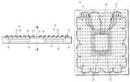
- FIG. 3is an enlarged cross-sectional view of a plurality of semiconductor packages formed in accordance with an embodiment of the present invention
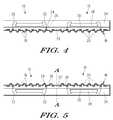
- FIG. 4is an enlarged cross-sectional view showing the semiconductor packages of FIG. 3 after removal of the substrate;
- FIG. 5is an enlarged cross-sectional view showing a second electrically insulating layer formed over a portion of the exposed electrically conductive pattern of FIG. 4 ;
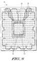
- FIG. 6is an enlarged schematic plan view of a semiconductor package in accordance with an embodiment of the present invention.
- the present inventionprovides a method of forming a semiconductor package including the step of forming a plurality of cavities in a substrate.
- An electrically conductive patternis formed on the substrate and over the cavities.
- An electrically insulating layeris formed over the substrate and the electrically conductive pattern.
- a plurality of viasis formed in the electrically insulating layer.
- An integrated circuit (IC) dieis attached to the electrically insulating layer and electrically connected to the vias such that the IC die is connected to the electrically conductive pattern.
- a molding operationis performed to encapsulate the IC die. The substrate is removed such that the electrically conductive pattern is exposed.
- the present inventionalso provides a method of forming a plurality of semiconductor packages including the step of forming a plurality of cavities in a substrate.
- An electrically conductive patternis formed on the substrate and atop the cavities.
- An electrically insulating layeris formed over the substrate and the electrically conductive pattern.
- a plurality of viasis formed in the electrically insulating layer.
- a plurality of integrated circuit (IC) diceis attached to the electrically insulating layer and electrically connected to the vias such that the IC dice are connected to the electrically conductive pattern.
- a molding operationis performed to encapsulate the IC dice.
- the substrateis subsequently removed such that the electrically conductive pattern is exposed.
- the present inventionalso provides a semiconductor package including an electrically insulating layer having a plurality of vias formed therein.
- An electrically conductive patternis formed on a first surface of the electrically insulating layer.
- An integrated circuit (IC) dieis attached to a second surface of the electrically insulating layer and electrically connected to the vias in the electrically insulating layer such that the IC die is connected to the electrically conductive pattern.
- the IC die and a portion of the second surface of the electrically insulating layerare encapsulated by a mold compound.
- the electrically conductive patternmay include a plurality of traces and a plurality of conductive bumps.
- the conductive bumpsmay be located on a central portion and a peripheral portion of the semiconductor package.
- a portion of the tracesmay extend between respective ones of the vias and respective ones of the conductive bumps located on the central portion of the semiconductor package.
- a second electrically insulating layermay be formed over the traces.
- FIGS. 1 through 5illustrate a method of forming a plurality of semiconductor packages 10 in accordance with an embodiment of the present invention.
- a substrate 12 having a plurality of cavities 14 formed thereinis shown.
- An electrically conductive pattern 16is formed on the substrate 12 and atop or over the cavities 14 .
- the electrically conductive pattern 16includes a plurality of traces 18 and a plurality of conductive bumps 20 , each of the conductive bumps 20 corresponding to respective ones of the cavities 14 .
- the substrate 12may comprise an electrically conductive material such as, for example, a strip of copper (Cu) foil or sheet and may have a thickness of between about 0.1 millimeter (mm) and about 1.0 mm. Nonetheless, it should be understood that the invention is not limited by the thickness of the substrate 12 .
- an electrically conductive materialsuch as, for example, a strip of copper (Cu) foil or sheet and may have a thickness of between about 0.1 millimeter (mm) and about 1.0 mm. Nonetheless, it should be understood that the invention is not limited by the thickness of the substrate 12 .
- the cavities 14may be formed in the substrate 12 in accordance with a predetermined land pattern for the semiconductor packages 10 .
- the cavities 14are formed in a full area array layout on the substrate 12 . That is, the cavities 14 are formed in regions of the substrate 12 corresponding to both central and peripheral portions of the semiconductor packages 10 . Nonetheless, it should be understood that the present invention is not limited to the layout as described.
- the cavities 14may, for example, be formed in a peripheral array layout on the substrate 12 , that is, only in regions of the substrate 12 corresponding to the peripheral portions of the semiconductor packages 10 .
- the cavities 14may have a pitch of between about 0.1 mm and about 1.0 mm. Nonetheless, it should be understood that the invention is not limited by the pitch between the cavities 14 .
- the cavities 14may be formed in the substrate 12 by applying a resist coating or laminating a dry film onto a surface of the substrate 12 , exposing and developing the resist or dry film to form a patterned resist or dry film with the desired land pattern, and thereafter etching the substrate 12 using the patterned resist or dry film as an etching mask. Subsequent to the etching of the substrate 12 , the patterned resist or dry film is stripped away.
- solder resist coating, dry film lamination and chemical etching technologiesare well known in the art of substrate manufacturing, further description of the formation of the cavities 14 in the substrate 12 is not required for a complete understanding of the present invention.
- the cavities 14may be formed in the substrate 12 to a depth of between about 100 microns ( ⁇ m) and about 1000 ⁇ m. Nonetheless, it should be understood that the invention is not limited by the depth to which the cavities 14 are formed.
- the electrically conductive pattern 16may be formed on the substrate 12 by depositing an electrically conductive material such as, for example, gold, nickel or copper onto the substrate 12 via an electroplating process and subsequently patterning the electrically conductive material to form the traces 18 and the conductive bumps 20 . Because metal buildup technologies such as electroplating are well known in the art of substrate manufacturing, further description of the formation of the electrically conductive pattern 16 on the substrate 12 is not required for a complete understanding of the present invention.
- an electrically insulating layer 22is formed over the substrate 12 and the electrically conductive pattern 16 of FIG. 1 as shown.
- a plurality of vias 24is formed in the electrically insulating layer 22 .
- a plurality of through-holes 26is formed through the electrically insulating layer 22 to the electrically conductive pattern 16 . Thereafter, the through-holes 26 are plated with an electrically conductive material to form the vias 24 .
- the electrically insulating layer 22may comprise a solder resist layer and may be formed over the substrate 12 and the electrically conductive pattern 16 by, for example, film lamination.
- the through-holes 26may be formed in the electrically insulating layer 22 by an exposure, development and thermal curing process or a laser blind via drilling process, both of which are known in the art.
- the through-holes 26may be plated with gold (Au), for example, or other electrically conductive material using a known electrolytic plating process.
- a plurality of integrated circuit (IC) dice 28is attached to the electrically insulating layer 22 of FIG. 2 and electrically connected to the vias 24 as shown. More particularly, the IC dice 28 are attached to respective die attach areas on the substrate 12 with a die attach adhesive 30 , and die pads of the IC dice 28 are electrically connected to the vias 24 in the substrate 12 with a plurality of bonding wires 32 such that the IC dice 28 are connected to the electrically conductive pattern 16 .
- a molding operationis performed to encapsulate the IC dice 28 and the bonding wires 32 with a mold compound 34 .
- the IC dice 28may be any type of circuit such as, for example, a digital signal processor (DSP) or a special function circuit.
- the IC dice 28are not limited to a particular technology such as CMOS, or derived from any particular wafer technology. Further, the present invention can accommodate IC dice 28 of various sizes; for example, the IC dice 28 may be between about 0.5 mm by 0.5 mm and about 20 mm by 20 mm in size.
- the IC dice 28may be attached to the respective die attach areas on the substrate 12 by dispensing the die attach adhesive 30 onto the respective bonding sites on the substrate 12 , placing the IC dice 28 on the respective bonding sites, and then curing the die attach adhesive 30 .
- the die attach adhesive 30may be a non-conductive liquid epoxy or a tape epoxy. Such epoxies are known in the art and commercially available.
- the bonding wires 32may be made of gold (Au), copper (Cu), aluminium (Al) or other electrically conductive materials as are known in the art and commercially available. A known wire bonding process may be used to form the electrical connections.
- a well known molding processsuch as, for example, injection molding may be used to encapsulate the IC dice 28 and the bonding wires 32 .
- the mold compound 34may comprise well known commercially available molding materials such as plastic or epoxy.
- the substrate 12is removed from the semiconductor packages 10 of FIG. 3 as shown, thereby exposing the electrically conductive pattern 16 .
- the substrate 12may be removed using a known chemical etching process.
- an ammoniac solution that dissolves only copper (Cu)may be used as an etchant to remove a substrate 12 made of copper.
- the exposed conductive bumps 20function as controlled collapse chip carrier connection (C 5 ) bumps on the semiconductor packages 10 .
- C 5controlled collapse chip carrier connection
- the electrically insulating layer 22functions as a stress relief layer, providing stress relief, for example, during thermal cycling after attachment of the semiconductor package 10 to a chip carrier. This reduces stresses on the C 5 joints and thus improves board joint reliability.
- the electrically insulating layer 22also absorbs some of the mechanical stress and strain on the bumps 20 during electrical testing, reducing the direct force impact imparted by a test socket.
- each of the bumps 20is formed with a rounded base.
- the rounded base of the bumps 20provides a self centering effect during attachment of the bumps 20 to respective pads of a chip carrier. It should however be understood that the present invention is not limited by the shape of the bumps 20 .
- the bumps 20may be shaped differently depending on the method by which the cavities 14 in the substrate 12 are formed.
- a second electrically insulating layer 36is formed over a portion of the exposed electrically conductive pattern 16 of FIG. 4 as shown. More particularly, the second electrically insulating layer 36 is formed over the exposed traces 18 . As shown in FIG. 5 , the semiconductor packages 10 of FIG. 4 are flipped or turned over for the formation of the second electrically insulating layer 36 . A singulating operation such as, for example, saw singulation may subsequently be performed to separate adjacent ones of the IC dice 28 along vertical line A-A to form individual semiconductor packages 10 .
- the second electrically insulating layer 36may, in one embodiment, be formed by forming a solder resist layer over the electrically conductive pattern 16 via film lamination and subsequently subjecting the solder resist layer to an exposure, development and thermal curing process to expose the bumps 20 .
- FIGS. 1 to 5show the formation of only two (2) semiconductor packages 10 , it will be understood that more than two semiconductor packages 10 may be formed simultaneously with the present invention.
- FIG. 6an enlarged schematic plan view of one of the semiconductor packages 10 of FIG. 5 is shown.
- the conductive bumps 20 of the semiconductor package 10are located on a central portion and a peripheral portion of the semiconductor package 10 . Nonetheless, it should be understood that the present invention is not limited to full area array packages. In alternative embodiments, the conductive bumps 20 may, for example, be formed only around a peripheral portion of the semiconductor package 10 .
- a portion of the traces 18extends between respective ones of the vias 24 and respective ones of the conductive bumps 20 located on the central portion of the semiconductor package 10 .
- IOinput/output
- the conductive bumps 20may have a pitch of between about 0.1 mm and about 1.0 mm and a diameter of between about 0.1 mm and about 1.0 mm. Nonetheless, it should be understood that the invention is not limited by the diameter of or pitch between the conductive bumps 20 .
- Semiconductor packages 10 with fine pitch interconnectsare thus achievable via the build up method described with reference to FIGS. 1 through 5 .
- the fine pitch BCC bumps 20enable smaller package footprints and/or high IO density.
- the present inventionprovides a method of forming semiconductor packages with increased IO densities. Additionally, because the C 5 bumps are incorporated as part of the semiconductor package, an additional step of C 5 solder ball attach at the assembly backend may be eliminated, along with any solder ball drop issues that may otherwise arise. Further advantageously, the insulation film formed over the C 5 bumps provides stress relieve to the C 5 bumps during electrical testing and also to the C 5 joints during thermal cycling.
Landscapes
- Engineering & Computer Science (AREA)
- Microelectronics & Electronic Packaging (AREA)
- Computer Hardware Design (AREA)
- Power Engineering (AREA)
- Physics & Mathematics (AREA)
- Condensed Matter Physics & Semiconductors (AREA)
- General Physics & Mathematics (AREA)
- Manufacturing & Machinery (AREA)
- Encapsulation Of And Coatings For Semiconductor Or Solid State Devices (AREA)
Abstract
Description
Claims (20)
Priority Applications (1)
| Application Number | Priority Date | Filing Date | Title |
|---|---|---|---|
| US12/234,709US7745260B2 (en) | 2008-09-22 | 2008-09-22 | Method of forming semiconductor package |
Applications Claiming Priority (1)
| Application Number | Priority Date | Filing Date | Title |
|---|---|---|---|
| US12/234,709US7745260B2 (en) | 2008-09-22 | 2008-09-22 | Method of forming semiconductor package |
Publications (2)
| Publication Number | Publication Date |
|---|---|
| US20100075462A1 US20100075462A1 (en) | 2010-03-25 |
| US7745260B2true US7745260B2 (en) | 2010-06-29 |
Family
ID=42038081
Family Applications (1)
| Application Number | Title | Priority Date | Filing Date |
|---|---|---|---|
| US12/234,709Active2029-03-12US7745260B2 (en) | 2008-09-22 | 2008-09-22 | Method of forming semiconductor package |
Country Status (1)
| Country | Link |
|---|---|
| US (1) | US7745260B2 (en) |
Cited By (4)
| Publication number | Priority date | Publication date | Assignee | Title |
|---|---|---|---|---|
| US20100188229A1 (en)* | 2009-01-26 | 2010-07-29 | Nhean Nhep | Safety shut off system for household appliances |
| US20110121449A1 (en)* | 2009-11-25 | 2011-05-26 | Stats Chippac, Ltd. | Semiconductor Device and Method of Forming Compliant Stress Relief Buffer Around Large Array WLCSP |
| US9202769B2 (en) | 2009-11-25 | 2015-12-01 | Stats Chippac, Ltd. | Semiconductor device and method of forming thermal lid for balancing warpage and thermal management |
| US12288770B2 (en) | 2022-04-25 | 2025-04-29 | Nxp B.V. | Semiconductor packages with embedded wiring on re-distributed bumps |
Families Citing this family (3)
| Publication number | Priority date | Publication date | Assignee | Title |
|---|---|---|---|---|
| US8288202B2 (en)* | 2010-11-22 | 2012-10-16 | STATS ChiPAC, Ltd. | Method of forming partially-etched conductive layer recessed within substrate for bonding to semiconductor die |
| US8981541B2 (en)* | 2013-07-10 | 2015-03-17 | Freescale Semiconductor, Inc. | Quad flat semiconductor device with additional contacts |
| EP3238676B1 (en) | 2016-04-29 | 2019-01-02 | The Procter and Gamble Company | Absorbent core with profiled distribution of absorbent material |
Citations (7)
| Publication number | Priority date | Publication date | Assignee | Title |
|---|---|---|---|---|
| US4259436A (en) | 1978-04-26 | 1981-03-31 | Shinko Electric Industries Co., Ltd. | Method of making a take-carrier for manufacturing IC elements |
| US6100112A (en) | 1998-05-28 | 2000-08-08 | The Furukawa Electric Co., Ltd. | Method of manufacturing a tape carrier with bump |
| US20020000829A1 (en)* | 1999-02-16 | 2002-01-03 | Micron Technology, Inc. | Test insert containing vias for interfacing a device containing contact bumps with a test substrate |
| US6344688B1 (en) | 1998-07-13 | 2002-02-05 | Institute Of Microelectronics | Very thin multi-chip package and method of mass producing the same |
| US6911729B1 (en) | 1999-05-14 | 2005-06-28 | Sharp Kabushiki Kaisha | Tape carrier semiconductor device |
| US7315086B2 (en) | 2004-11-03 | 2008-01-01 | Samsung Electronics Co., Ltd. | Chip-on-board package having flip chip assembly structure and manufacturing method thereof |
| US20080199980A1 (en)* | 2007-02-16 | 2008-08-21 | Masao Okayama | Method of manufacturing a semiconductor integrated circuit device |
- 2008
- 2008-09-22USUS12/234,709patent/US7745260B2/enactiveActive
Patent Citations (7)
| Publication number | Priority date | Publication date | Assignee | Title |
|---|---|---|---|---|
| US4259436A (en) | 1978-04-26 | 1981-03-31 | Shinko Electric Industries Co., Ltd. | Method of making a take-carrier for manufacturing IC elements |
| US6100112A (en) | 1998-05-28 | 2000-08-08 | The Furukawa Electric Co., Ltd. | Method of manufacturing a tape carrier with bump |
| US6344688B1 (en) | 1998-07-13 | 2002-02-05 | Institute Of Microelectronics | Very thin multi-chip package and method of mass producing the same |
| US20020000829A1 (en)* | 1999-02-16 | 2002-01-03 | Micron Technology, Inc. | Test insert containing vias for interfacing a device containing contact bumps with a test substrate |
| US6911729B1 (en) | 1999-05-14 | 2005-06-28 | Sharp Kabushiki Kaisha | Tape carrier semiconductor device |
| US7315086B2 (en) | 2004-11-03 | 2008-01-01 | Samsung Electronics Co., Ltd. | Chip-on-board package having flip chip assembly structure and manufacturing method thereof |
| US20080199980A1 (en)* | 2007-02-16 | 2008-08-21 | Masao Okayama | Method of manufacturing a semiconductor integrated circuit device |
Cited By (7)
| Publication number | Priority date | Publication date | Assignee | Title |
|---|---|---|---|---|
| US20100188229A1 (en)* | 2009-01-26 | 2010-07-29 | Nhean Nhep | Safety shut off system for household appliances |
| US20110121449A1 (en)* | 2009-11-25 | 2011-05-26 | Stats Chippac, Ltd. | Semiconductor Device and Method of Forming Compliant Stress Relief Buffer Around Large Array WLCSP |
| US8034661B2 (en)* | 2009-11-25 | 2011-10-11 | Stats Chippac, Ltd. | Semiconductor device and method of forming compliant stress relief buffer around large array WLCSP |
| US8912648B2 (en) | 2009-11-25 | 2014-12-16 | Stats Chippac, Ltd. | Semiconductor device and method of forming compliant stress relief buffer around large array WLCSP |
| US9202769B2 (en) | 2009-11-25 | 2015-12-01 | Stats Chippac, Ltd. | Semiconductor device and method of forming thermal lid for balancing warpage and thermal management |
| US9508621B2 (en) | 2009-11-25 | 2016-11-29 | STATS ChipPAC Pte. Ltd. | Semiconductor device and method of forming compliant stress relief buffer around large array WLCSP |
| US12288770B2 (en) | 2022-04-25 | 2025-04-29 | Nxp B.V. | Semiconductor packages with embedded wiring on re-distributed bumps |
Also Published As
| Publication number | Publication date |
|---|---|
| US20100075462A1 (en) | 2010-03-25 |
Similar Documents
| Publication | Publication Date | Title |
|---|---|---|
| TWI879914B (en) | Semiconductor package and method of fabricating the same | |
| KR101349985B1 (en) | Method for packaging a semiconductor device | |
| JP6057190B2 (en) | Method for manufacturing semiconductor element or package | |
| US9165878B2 (en) | Semiconductor packages and methods of packaging semiconductor devices | |
| US8643161B2 (en) | Semiconductor device having double side electrode structure | |
| US8273601B2 (en) | Method of fabricating multi-chip package structure | |
| US9209146B2 (en) | Electronic device packages having bumps and methods of manufacturing the same | |
| US7977161B2 (en) | Method of manufacturing a semiconductor package using a carrier | |
| US7473586B1 (en) | Method of forming flip-chip bump carrier type package | |
| US7745260B2 (en) | Method of forming semiconductor package | |
| EP0843357B1 (en) | Method of manufacturing a grid array semiconductor package | |
| US20250155105A1 (en) | Semiconductor device and manufacturing method thereof | |
| US8872329B1 (en) | Extended landing pad substrate package structure and method | |
| US20070114661A1 (en) | Semiconductor package and method of fabricating the same | |
| US7232755B1 (en) | Process for fabricating pad frame and integrated circuit package | |
| KR20080045017A (en) | Semiconductor chip package having metal bumps and manufacturing method thereof | |
| JP2004063742A (en) | Wiring board, semiconductor package and method for manufacturing them | |
| JP4626063B2 (en) | Manufacturing method of semiconductor device | |
| KR20130059580A (en) | Semiconductor package and method for manufacturing the same | |
| US20080303150A1 (en) | High-Density Fine Line Structure And Method Of Manufacturing The Same |
Legal Events
| Date | Code | Title | Description |
|---|---|---|---|
| AS | Assignment | Owner name:FREESCALE SEMICONDUCTOR, INC.,TEXAS Free format text:ASSIGNMENT OF ASSIGNORS INTEREST;ASSIGNOR:FREESCALE SEMICONDUCTOR, INC.;REEL/FRAME:021560/0816 Effective date:20080922 | |
| AS | Assignment | Owner name:FREESCALE SEMICONDUCTOR, INC.,TEXAS Free format text:CORRECTIVE ASSIGNMENT TO CORRECT THE CONVEYING PARTY DATA PREVIOUSLY RECORDED ON REEL 021560 FRAME 0816. ASSIGNOR(S) HEREBY CONFIRMS THE FREESCALE SEMICONDUCTOR, INC TO WAI YEW LO;ASSIGNOR:LO, WAI YEW;REEL/FRAME:021574/0827 Effective date:20080908 | |
| AS | Assignment | Owner name:CITIBANK, N.A., NEW YORK Free format text:SECURITY AGREEMENT;ASSIGNOR:FREESCALE SEMICONDUCTOR, INC.;REEL/FRAME:021936/0772 Effective date:20081107 Owner name:CITIBANK, N.A.,NEW YORK Free format text:SECURITY AGREEMENT;ASSIGNOR:FREESCALE SEMICONDUCTOR, INC.;REEL/FRAME:021936/0772 Effective date:20081107 | |
| FEPP | Fee payment procedure | Free format text:PAYER NUMBER DE-ASSIGNED (ORIGINAL EVENT CODE: RMPN); ENTITY STATUS OF PATENT OWNER: LARGE ENTITY Free format text:PAYOR NUMBER ASSIGNED (ORIGINAL EVENT CODE: ASPN); ENTITY STATUS OF PATENT OWNER: LARGE ENTITY | |
| AS | Assignment | Owner name:CITIBANK, N.A., AS COLLATERAL AGENT, NEW YORK Free format text:SECURITY AGREEMENT;ASSIGNOR:FREESCALE SEMICONDUCTOR, INC.;REEL/FRAME:024397/0001 Effective date:20100413 Owner name:CITIBANK, N.A., AS COLLATERAL AGENT,NEW YORK Free format text:SECURITY AGREEMENT;ASSIGNOR:FREESCALE SEMICONDUCTOR, INC.;REEL/FRAME:024397/0001 Effective date:20100413 | |
| STCF | Information on status: patent grant | Free format text:PATENTED CASE | |
| AS | Assignment | Owner name:CITIBANK, N.A., AS NOTES COLLATERAL AGENT, NEW YORK Free format text:SECURITY AGREEMENT;ASSIGNOR:FREESCALE SEMICONDUCTOR, INC.;REEL/FRAME:030633/0424 Effective date:20130521 Owner name:CITIBANK, N.A., AS NOTES COLLATERAL AGENT, NEW YOR Free format text:SECURITY AGREEMENT;ASSIGNOR:FREESCALE SEMICONDUCTOR, INC.;REEL/FRAME:030633/0424 Effective date:20130521 | |
| AS | Assignment | Owner name:CITIBANK, N.A., AS NOTES COLLATERAL AGENT, NEW YORK Free format text:SECURITY AGREEMENT;ASSIGNOR:FREESCALE SEMICONDUCTOR, INC.;REEL/FRAME:031591/0266 Effective date:20131101 Owner name:CITIBANK, N.A., AS NOTES COLLATERAL AGENT, NEW YOR Free format text:SECURITY AGREEMENT;ASSIGNOR:FREESCALE SEMICONDUCTOR, INC.;REEL/FRAME:031591/0266 Effective date:20131101 | |
| FPAY | Fee payment | Year of fee payment:4 | |
| AS | Assignment | Owner name:FREESCALE SEMICONDUCTOR, INC., TEXAS Free format text:PATENT RELEASE;ASSIGNOR:CITIBANK, N.A., AS COLLATERAL AGENT;REEL/FRAME:037356/0553 Effective date:20151207 Owner name:FREESCALE SEMICONDUCTOR, INC., TEXAS Free format text:PATENT RELEASE;ASSIGNOR:CITIBANK, N.A., AS COLLATERAL AGENT;REEL/FRAME:037354/0757 Effective date:20151207 | |
| AS | Assignment | Owner name:MORGAN STANLEY SENIOR FUNDING, INC., MARYLAND Free format text:ASSIGNMENT AND ASSUMPTION OF SECURITY INTEREST IN PATENTS;ASSIGNOR:CITIBANK, N.A.;REEL/FRAME:037486/0517 Effective date:20151207 | |
| AS | Assignment | Owner name:MORGAN STANLEY SENIOR FUNDING, INC., MARYLAND Free format text:ASSIGNMENT AND ASSUMPTION OF SECURITY INTEREST IN PATENTS;ASSIGNOR:CITIBANK, N.A.;REEL/FRAME:037518/0292 Effective date:20151207 | |
| AS | Assignment | Owner name:MORGAN STANLEY SENIOR FUNDING, INC., MARYLAND Free format text:SECURITY AGREEMENT SUPPLEMENT;ASSIGNOR:NXP B.V.;REEL/FRAME:038017/0058 Effective date:20160218 | |
| AS | Assignment | Owner name:MORGAN STANLEY SENIOR FUNDING, INC., MARYLAND Free format text:SUPPLEMENT TO THE SECURITY AGREEMENT;ASSIGNOR:FREESCALE SEMICONDUCTOR, INC.;REEL/FRAME:039138/0001 Effective date:20160525 | |
| AS | Assignment | Owner name:MORGAN STANLEY SENIOR FUNDING, INC., MARYLAND Free format text:CORRECTIVE ASSIGNMENT TO CORRECT THE REMOVE APPLICATION 12092129 PREVIOUSLY RECORDED ON REEL 038017 FRAME 0058. ASSIGNOR(S) HEREBY CONFIRMS THE SECURITY AGREEMENT SUPPLEMENT;ASSIGNOR:NXP B.V.;REEL/FRAME:039361/0212 Effective date:20160218 | |
| AS | Assignment | Owner name:NXP, B.V., F/K/A FREESCALE SEMICONDUCTOR, INC., NETHERLANDS Free format text:RELEASE BY SECURED PARTY;ASSIGNOR:MORGAN STANLEY SENIOR FUNDING, INC.;REEL/FRAME:040925/0001 Effective date:20160912 Owner name:NXP, B.V., F/K/A FREESCALE SEMICONDUCTOR, INC., NE Free format text:RELEASE BY SECURED PARTY;ASSIGNOR:MORGAN STANLEY SENIOR FUNDING, INC.;REEL/FRAME:040925/0001 Effective date:20160912 | |
| AS | Assignment | Owner name:NXP B.V., NETHERLANDS Free format text:RELEASE BY SECURED PARTY;ASSIGNOR:MORGAN STANLEY SENIOR FUNDING, INC.;REEL/FRAME:040928/0001 Effective date:20160622 | |
| AS | Assignment | Owner name:NXP USA, INC., TEXAS Free format text:CHANGE OF NAME;ASSIGNOR:FREESCALE SEMICONDUCTOR, INC.;REEL/FRAME:040632/0001 Effective date:20161107 | |
| AS | Assignment | Owner name:MORGAN STANLEY SENIOR FUNDING, INC., MARYLAND Free format text:CORRECTIVE ASSIGNMENT TO CORRECT THE REMOVE PATENTS 8108266 AND 8062324 AND REPLACE THEM WITH 6108266 AND 8060324 PREVIOUSLY RECORDED ON REEL 037518 FRAME 0292. ASSIGNOR(S) HEREBY CONFIRMS THE ASSIGNMENT AND ASSUMPTION OF SECURITY INTEREST IN PATENTS;ASSIGNOR:CITIBANK, N.A.;REEL/FRAME:041703/0536 Effective date:20151207 | |
| AS | Assignment | Owner name:MORGAN STANLEY SENIOR FUNDING, INC., MARYLAND Free format text:CORRECTIVE ASSIGNMENT TO CORRECT THE REMOVE APPLICATION 12681366 PREVIOUSLY RECORDED ON REEL 038017 FRAME 0058. ASSIGNOR(S) HEREBY CONFIRMS THE SECURITY AGREEMENT SUPPLEMENT;ASSIGNOR:NXP B.V.;REEL/FRAME:042985/0001 Effective date:20160218 Owner name:MORGAN STANLEY SENIOR FUNDING, INC., MARYLAND Free format text:CORRECTIVE ASSIGNMENT TO CORRECT THE REMOVE APPLICATION 12681366 PREVIOUSLY RECORDED ON REEL 039361 FRAME 0212. ASSIGNOR(S) HEREBY CONFIRMS THE SECURITY AGREEMENT SUPPLEMENT;ASSIGNOR:NXP B.V.;REEL/FRAME:042762/0145 Effective date:20160218 | |
| MAFP | Maintenance fee payment | Free format text:PAYMENT OF MAINTENANCE FEE, 8TH YEAR, LARGE ENTITY (ORIGINAL EVENT CODE: M1552) Year of fee payment:8 | |
| AS | Assignment | Owner name:NXP USA, INC., TEXAS Free format text:CORRECTIVE ASSIGNMENT TO CORRECT THE NATURE OF CONVEYANCE PREVIOUSLY RECORDED AT REEL: 040632 FRAME: 0001. ASSIGNOR(S) HEREBY CONFIRMS THE MERGER AND CHANGE OF NAME;ASSIGNOR:FREESCALE SEMICONDUCTOR INC.;REEL/FRAME:044209/0047 Effective date:20161107 | |
| AS | Assignment | Owner name:SHENZHEN XINGUODU TECHNOLOGY CO., LTD., CHINA Free format text:CORRECTIVE ASSIGNMENT TO CORRECT THE TO CORRECT THE APPLICATION NO. FROM 13,883,290 TO 13,833,290 PREVIOUSLY RECORDED ON REEL 041703 FRAME 0536. ASSIGNOR(S) HEREBY CONFIRMS THE THE ASSIGNMENT AND ASSUMPTION OF SECURITYINTEREST IN PATENTS.;ASSIGNOR:MORGAN STANLEY SENIOR FUNDING, INC.;REEL/FRAME:048734/0001 Effective date:20190217 | |
| AS | Assignment | Owner name:NXP B.V., NETHERLANDS Free format text:RELEASE BY SECURED PARTY;ASSIGNOR:MORGAN STANLEY SENIOR FUNDING, INC.;REEL/FRAME:050744/0097 Effective date:20190903 Owner name:NXP B.V., NETHERLANDS Free format text:RELEASE BY SECURED PARTY;ASSIGNOR:MORGAN STANLEY SENIOR FUNDING, INC.;REEL/FRAME:050745/0001 Effective date:20190903 | |
| AS | Assignment | Owner name:MORGAN STANLEY SENIOR FUNDING, INC., MARYLAND Free format text:CORRECTIVE ASSIGNMENT TO CORRECT THE REMOVE APPLICATION 12298143 PREVIOUSLY RECORDED ON REEL 042985 FRAME 0001. ASSIGNOR(S) HEREBY CONFIRMS THE SECURITY AGREEMENT SUPPLEMENT;ASSIGNOR:NXP B.V.;REEL/FRAME:051029/0001 Effective date:20160218 Owner name:MORGAN STANLEY SENIOR FUNDING, INC., MARYLAND Free format text:CORRECTIVE ASSIGNMENT TO CORRECT THE REMOVE APPLICATION 12298143 PREVIOUSLY RECORDED ON REEL 042762 FRAME 0145. ASSIGNOR(S) HEREBY CONFIRMS THE SECURITY AGREEMENT SUPPLEMENT;ASSIGNOR:NXP B.V.;REEL/FRAME:051145/0184 Effective date:20160218 Owner name:MORGAN STANLEY SENIOR FUNDING, INC., MARYLAND Free format text:CORRECTIVE ASSIGNMENT TO CORRECT THE REMOVE APPLICATION 12298143 PREVIOUSLY RECORDED ON REEL 039361 FRAME 0212. ASSIGNOR(S) HEREBY CONFIRMS THE SECURITY AGREEMENT SUPPLEMENT;ASSIGNOR:NXP B.V.;REEL/FRAME:051029/0387 Effective date:20160218 Owner name:MORGAN STANLEY SENIOR FUNDING, INC., MARYLAND Free format text:CORRECTIVE ASSIGNMENT TO CORRECT THE REMOVE APPLICATION12298143 PREVIOUSLY RECORDED ON REEL 042762 FRAME 0145. ASSIGNOR(S) HEREBY CONFIRMS THE SECURITY AGREEMENT SUPPLEMENT;ASSIGNOR:NXP B.V.;REEL/FRAME:051145/0184 Effective date:20160218 Owner name:MORGAN STANLEY SENIOR FUNDING, INC., MARYLAND Free format text:CORRECTIVE ASSIGNMENT TO CORRECT THE REMOVE APPLICATION12298143 PREVIOUSLY RECORDED ON REEL 039361 FRAME 0212. ASSIGNOR(S) HEREBY CONFIRMS THE SECURITY AGREEMENT SUPPLEMENT;ASSIGNOR:NXP B.V.;REEL/FRAME:051029/0387 Effective date:20160218 Owner name:MORGAN STANLEY SENIOR FUNDING, INC., MARYLAND Free format text:CORRECTIVE ASSIGNMENT TO CORRECT THE REMOVE APPLICATION12298143 PREVIOUSLY RECORDED ON REEL 042985 FRAME 0001. ASSIGNOR(S) HEREBY CONFIRMS THE SECURITY AGREEMENT SUPPLEMENT;ASSIGNOR:NXP B.V.;REEL/FRAME:051029/0001 Effective date:20160218 Owner name:MORGAN STANLEY SENIOR FUNDING, INC., MARYLAND Free format text:CORRECTIVE ASSIGNMENT TO CORRECT THE REMOVE APPLICATION 12298143 PREVIOUSLY RECORDED ON REEL 038017 FRAME 0058. ASSIGNOR(S) HEREBY CONFIRMS THE SECURITY AGREEMENT SUPPLEMENT;ASSIGNOR:NXP B.V.;REEL/FRAME:051030/0001 Effective date:20160218 | |
| AS | Assignment | Owner name:MORGAN STANLEY SENIOR FUNDING, INC., MARYLAND Free format text:CORRECTIVE ASSIGNMENT TO CORRECT THE REMOVE APPLICATION11759915 AND REPLACE IT WITH APPLICATION 11759935 PREVIOUSLY RECORDED ON REEL 037486 FRAME 0517. ASSIGNOR(S) HEREBY CONFIRMS THE ASSIGNMENT AND ASSUMPTION OF SECURITYINTEREST IN PATENTS;ASSIGNOR:CITIBANK, N.A.;REEL/FRAME:053547/0421 Effective date:20151207 | |
| AS | Assignment | Owner name:NXP B.V., NETHERLANDS Free format text:CORRECTIVE ASSIGNMENT TO CORRECT THE REMOVEAPPLICATION 11759915 AND REPLACE IT WITH APPLICATION11759935 PREVIOUSLY RECORDED ON REEL 040928 FRAME 0001. ASSIGNOR(S) HEREBY CONFIRMS THE RELEASE OF SECURITYINTEREST;ASSIGNOR:MORGAN STANLEY SENIOR FUNDING, INC.;REEL/FRAME:052915/0001 Effective date:20160622 | |
| AS | Assignment | Owner name:NXP, B.V. F/K/A FREESCALE SEMICONDUCTOR, INC., NETHERLANDS Free format text:CORRECTIVE ASSIGNMENT TO CORRECT THE REMOVEAPPLICATION 11759915 AND REPLACE IT WITH APPLICATION11759935 PREVIOUSLY RECORDED ON REEL 040925 FRAME 0001. ASSIGNOR(S) HEREBY CONFIRMS THE RELEASE OF SECURITYINTEREST;ASSIGNOR:MORGAN STANLEY SENIOR FUNDING, INC.;REEL/FRAME:052917/0001 Effective date:20160912 | |
| MAFP | Maintenance fee payment | Free format text:PAYMENT OF MAINTENANCE FEE, 12TH YEAR, LARGE ENTITY (ORIGINAL EVENT CODE: M1553); ENTITY STATUS OF PATENT OWNER: LARGE ENTITY Year of fee payment:12 |