US7744623B2 - Vessel occlusion clamp - Google Patents
Vessel occlusion clampDownload PDFInfo
- Publication number
- US7744623B2 US7744623B2US11/184,174US18417405AUS7744623B2US 7744623 B2US7744623 B2US 7744623B2US 18417405 AUS18417405 AUS 18417405AUS 7744623 B2US7744623 B2US 7744623B2
- Authority
- US
- United States
- Prior art keywords
- jaw
- axis
- insert
- along
- width
- Prior art date
- Legal status (The legal status is an assumption and is not a legal conclusion. Google has not performed a legal analysis and makes no representation as to the accuracy of the status listed.)
- Expired - Fee Related, expires
Links
Images

Classifications
- A—HUMAN NECESSITIES
- A61—MEDICAL OR VETERINARY SCIENCE; HYGIENE
- A61B—DIAGNOSIS; SURGERY; IDENTIFICATION
- A61B17/00—Surgical instruments, devices or methods
- A61B17/28—Surgical forceps
- A61B17/2812—Surgical forceps with a single pivotal connection
- A61B17/282—Jaws
- A—HUMAN NECESSITIES
- A61—MEDICAL OR VETERINARY SCIENCE; HYGIENE
- A61B—DIAGNOSIS; SURGERY; IDENTIFICATION
- A61B17/00—Surgical instruments, devices or methods
- A61B17/12—Surgical instruments, devices or methods for ligaturing or otherwise compressing tubular parts of the body, e.g. blood vessels or umbilical cord
- A61B17/122—Clamps or clips, e.g. for the umbilical cord
- A—HUMAN NECESSITIES
- A61—MEDICAL OR VETERINARY SCIENCE; HYGIENE
- A61B—DIAGNOSIS; SURGERY; IDENTIFICATION
- A61B17/00—Surgical instruments, devices or methods
- A61B17/28—Surgical forceps
- A61B2017/2808—Clamp, e.g. towel clamp
- A—HUMAN NECESSITIES
- A61—MEDICAL OR VETERINARY SCIENCE; HYGIENE
- A61B—DIAGNOSIS; SURGERY; IDENTIFICATION
- A61B17/00—Surgical instruments, devices or methods
- A61B17/28—Surgical forceps
- A61B17/2812—Surgical forceps with a single pivotal connection
- A61B17/282—Jaws
- A61B2017/2825—Inserts of different material in jaws
Definitions
- This inventionrelates generally to surgical clamps, and more specifically to blood vessel occlusion clamps.
- Surgical occlusion clampsare commonly used to close off or occlude body conduits, such as blood vessels.
- a common variety of vessel occlusion clampis that referred to as a “Bahnson” clamp, which has small metal handles that operate a pair of opposing jaws. When the jaws are brought into close proximity on either side of a vessel, the vessel is squeezed against itself to achieve at least partial occlusion. It is of particular importance that the jaws of the clamp be stable, and sufficiently inflexible that the jaws do not cross over or scissor, but rather press directly against each other along their length to occlude any conduit disposed between the jaws.
- jaw insertshave been provided, but typically have had exposed edges, ends, and corners, which tend to entrap or entangle surgical sutures.
- a vessel occlusion clamp of the Bruson typeis provided with improved stability and reduced flexibility, while maintaining a low-profile jaw design.
- the jawsare provided with a receding or tapered T-beam cross section, which greatly reduces the bendibility or flexibility of the jaws.
- Other dimensional-shaped cross sections of interestinclude a U-beam cross section, an I-beam cross section, a trapezoidal I-beam cross section, a continuous or whole-length T-beam cross section, a B-channel cross section, and an L-beam cross section.
- transverse members forming the beam cross sectionscan be relied on to provide shielding of the jaw insert edges. This shielding prevents entrapment or entanglement of surgical sutures. Scallops or hollowed recesses can be provided in the jaws to facilitate installation and removal of the inserts without degrading structural jaw stability.
- a surgical clampis adapted for use in occluding a body conduit.
- the clampincludes a first jaw, and a second jaw movable relative to the first jaw in a generally parallel relationship.
- a handle assemblyis operable to move the first and second jaws relative to each other between a spaced position and a proximate position.
- the first jawhas an elongate configuration characterized by a length and a width.
- First portions of the first jawhave in radial cross section a first shape which remains generally constant in area along the length of the first jaw.
- Second portions of the first jawhave in cross section a second shape which changes in area along the length of the first jaw.
- the first portionswill typically have a first width while the second portions will have a second width greater than the first width.
- An insertis adapted to be removably mounted on the first portions with the second portions extending laterally of the insert.
- the surgical clampincludes a handle assembly and a pair of opposing jaws movable by the handle assembly in a plane of operation between a spaced orientation, wherein the jaws are spread to recede the body conduit, and a proximal orientation wherein the jaws are substantially closed to occlude the body conduit.
- At least one of the jawshas in cross section a non-rectangular configuration.
- An insert having a first widthis carried by first portions of the jaw which have a second width. Second portions of the jaw have a third width which defines with the first portions the thickness of the jaw. The first width of the insert is less than the third width of the second portions and greater than the second width of the first portions.
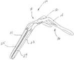
- FIG. 1is a front side perspective view of a vessel occlusion clamp of the Bruson type, illustrating disposable inserts mounted on parallel jaws having a dimensional-shaped, cross section design;
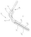
- FIG. 2is a perspective view similar to FIG. 1 , showing the jaws with the disposable inserts removed;
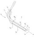
- FIG. 3is a side-elevation view of a clamp jaw illustrating a tapered, T-beam cross section
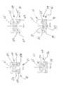
- FIG. 4is a cross section view taken along lines A-A of FIG. 3 ;
- FIG. 5is a cross section view taken along lines B-B of FIG. 3 ;
- FIG. 6is a cross section view similar to FIG. 5 and illustrating a trapezoidal I-beam cross section
- FIG. 7is a cross section view similar to FIG. 5 and illustrating a U-channel cross section
- FIG. 8is a cross section view similar to FIG. 5 and illustrating a V-beam cross section
- FIG. 9is a cross section view similar to FIG. 5 and illustrating an I-beam cross section.
- FIG. 10is a cross section view similar to FIG. 5 and illustrating an L-beam cross section.
- FIG. 1A vascular occlusion clamp of the Bruson type is illustrated in FIG. 1 and designated generally by the referenced numeral 10 .
- the clamp 10includes a pair of handles 12 and 14 with a ratchet lock 16 , which pivot on a fulcrum 18 to move jaws 21 and 23 in a generally parallel relationship.
- Disposable inserts 25 and 27are removably mounted on the associated jaws 21 , 23 .
- the inserts 25 and 27have been removed in order to illustrate the dimensional-shaped design of the jaws 21 and 23 . From this view it can be seen that the jaws 21 and 23 extend along a Z axis but move generally along an X axis. The width of the jaws is measured along a Y axis.
- the jawshaving a length along the Z axis, a width along the Y axis, and a thickness along the X axis.
- This dimensional-shaped designis further illustrated in the side-elevation view of FIG. 3 and the associated cross sectional views of FIGS. 4 and 5 .
- the side elevation view of FIG. 3is drawn in the YZ plane while the cross sectional views of FIGS. 4 and 5 are drawn in the XY plane.
- a preferred disposition of the associated insert 25is illustrated in dotted lines.
- the jaw 21has an engagement section 29 with a generally constant profile along its length. This engagement section 29 is intended to occupy a channel within the associated insert 25 .
- the jaw 21also includes a support section 31 which, in cross section forms a T with the elongate section 29 . It is this support section 31 that provides this embodiment with its dimensional-shaped structure. In this case, the support section 31 tapers from a narrow width at the distal end of the jaw 21 to a maximum width near the proximal end of the jaw 21 . With this dimensional-shaped configuration, the cross section of the jaw 21 is provided with substantially increased beam stiffness along the X axis and reduced transverse deflection along the Y axis.
- the support section 31can also be relied on to shield the edges, ends, and corners of the insert 25 that can entrap or entangle surgical sutures. With the shielding provided by these transverse elements, the edges, ends, and corners are not as prominent. While this prevents entrapment of surgical sutures, it can also make it more difficult to remove the inserts 25 and 27 for disposal. It is for this reason that the embodiment of FIG. 3 is provided with scallops or hollow recesses 33 and 35 , which provide shallow access to a proximal edge of each insert. With these recesses 33 and 35 provided in proximity to counterbored pin recesses 37 , 39 ( FIG. 2 ), the inserts 25 and 27 can be easily engaged and removed.
- FIGS. 6-10Other dimensional-shaped cross sectional designs providing these advantages are illustrated in FIGS. 6-10 .
- Each of these non-rectangular shaped cross sectionsprovide increased beam stiffness and reduce transverse deflection, compared to the rectangular cross sections of prior designs.
- the jaw 21has a trapezoidal I-beam shape characterized by an inner flange 41 joined to an outer flange 43 by a center flange 45 .
- the inner flange 41 and the center flange 45formed the engagement section 29 which is disposed in the channel of the insert 25 .
- the outer flange 43forms the support section 31 and maintains an abutting relationship with the insert 25 .
- This I-beam shapehas a trapezoidal configuration in that the inner flange 41 has a width less than the outer flange 43 .
- the jaw 21 in cross sectionhas a generally U-shaped configuration.
- a center flange 50is supported by two side flanges 52 and 54 which extend to outwardly directed flanges 56 and 58 respectively.
- the center flange 50 and side flanges 52 and 54form the engagement section 29 while the outwardly directed flanges 56 and 58 form the support section 31 .
- the engagement section 29is received within a center channel of the insert 25 while the support section 31 is disposed in an abutting relationship with the insert 25 .
- FIG. 8includes a jaw 21 having in cross section a V-shaped configuration.
- This embodimentincludes a top flange 61 supported by side flanges 63 and 65 which extend to outwardly directed flanges 67 and 69 , respectively.
- the side flanges 63 and 65are disposed at an acute angle with respect to the top flange 61 and are also disposed at an angle with respect to each other.
- the top flange 61 and side flanges 63 and 65form the engagement section 29 and are adapted to be disposed within a channel of the insert 25 .
- the outwardly directed flanges 67 and 69form the support section 31 and are disposed in an abutting relationship with the insert 25 .
- FIG. 9includes a jaw 21 , having in cross section an I-Beam shape similar to that of FIG. 6 .
- the jaw 21has a top flange 72 , joined to a bottom flange 74 by a center flange 76 .
- the top flange 72has the same width as the bottom flange 74 , but a greater thickness than the bottom flange 74 .
- the flanges 72 , 74 and 76are all disposed within the channel of the insert 25 . Accordingly, these three flanges in the illustrated embodiment form the engagement section 29 of the jaw 21 .
- the jaw 21 in cross sectionhas a U-shaped configuration.
- This embodimentis characterized by a bottom flange 81 , side flanges 83 and 85 , and a center flange 87 .
- the side flanges 83 and 85are equally spaced from the bottom flange 87 and extend from a side of the bottom flange 81 , opposite to that of the center flange 87 .
- Outwardly directed flanges 89 and 91extend from the bottom flange 81 outwardly of the side flanges 83 and 85 .
- portions of the bottom flange 81 together with the side flanges 83 and 85form the engagement section 29 .
- the remaining portions of the bottom flange 81 together with the outwardly directed flanges 89 and 91 and the bottom flange 87form the support section 31 .
- the resulting clamp 10maintains the desired low profile jaw design, while the dimensional-shaped cross sections provide increased stiffness and reduced flexibility. As a result, transverse deflection is substantially avoided.
- the dimensional-shaped cross sectionalso provides shielding to prevent entanglement of surgical sutures, while the scalloped and hollowed recessed 33 and 35 facilitate removal of the inserts 25 and 27 .
Landscapes
- Health & Medical Sciences (AREA)
- Surgery (AREA)
- Life Sciences & Earth Sciences (AREA)
- Medical Informatics (AREA)
- Animal Behavior & Ethology (AREA)
- Engineering & Computer Science (AREA)
- Biomedical Technology (AREA)
- Heart & Thoracic Surgery (AREA)
- Veterinary Medicine (AREA)
- Molecular Biology (AREA)
- Nuclear Medicine, Radiotherapy & Molecular Imaging (AREA)
- General Health & Medical Sciences (AREA)
- Public Health (AREA)
- Ophthalmology & Optometry (AREA)
- Reproductive Health (AREA)
- Vascular Medicine (AREA)
- Surgical Instruments (AREA)
Abstract
Description
Claims (17)
Priority Applications (2)
| Application Number | Priority Date | Filing Date | Title |
|---|---|---|---|
| US11/184,174US7744623B2 (en) | 1999-12-03 | 2005-07-18 | Vessel occlusion clamp |
| US12/816,041US8740933B2 (en) | 1999-12-03 | 2010-06-15 | Vessel occlusion clamp |
Applications Claiming Priority (4)
| Application Number | Priority Date | Filing Date | Title |
|---|---|---|---|
| US16894399P | 1999-12-03 | 1999-12-03 | |
| PCT/US2000/042390WO2001043623A2 (en) | 1999-12-03 | 2000-11-29 | Vessel occlusion clamp |
| US10/129,517US6932825B2 (en) | 1999-12-03 | 2000-11-29 | Vessel occlusion clamp |
| US11/184,174US7744623B2 (en) | 1999-12-03 | 2005-07-18 | Vessel occlusion clamp |
Related Parent Applications (2)
| Application Number | Title | Priority Date | Filing Date |
|---|---|---|---|
| PCT/US2000/042390ContinuationWO2001043623A2 (en) | 1999-12-03 | 2000-11-29 | Vessel occlusion clamp |
| US10/129,517ContinuationUS6932825B2 (en) | 1999-12-03 | 2000-11-29 | Vessel occlusion clamp |
Related Child Applications (1)
| Application Number | Title | Priority Date | Filing Date |
|---|---|---|---|
| US12/816,041ContinuationUS8740933B2 (en) | 1999-12-03 | 2010-06-15 | Vessel occlusion clamp |
Publications (2)
| Publication Number | Publication Date |
|---|---|
| US20050251184A1 US20050251184A1 (en) | 2005-11-10 |
| US7744623B2true US7744623B2 (en) | 2010-06-29 |
Family
ID=22613619
Family Applications (3)
| Application Number | Title | Priority Date | Filing Date |
|---|---|---|---|
| US10/129,517Expired - LifetimeUS6932825B2 (en) | 1999-12-03 | 2000-11-29 | Vessel occlusion clamp |
| US11/184,174Expired - Fee RelatedUS7744623B2 (en) | 1999-12-03 | 2005-07-18 | Vessel occlusion clamp |
| US12/816,041Expired - Fee RelatedUS8740933B2 (en) | 1999-12-03 | 2010-06-15 | Vessel occlusion clamp |
Family Applications Before (1)
| Application Number | Title | Priority Date | Filing Date |
|---|---|---|---|
| US10/129,517Expired - LifetimeUS6932825B2 (en) | 1999-12-03 | 2000-11-29 | Vessel occlusion clamp |
Family Applications After (1)
| Application Number | Title | Priority Date | Filing Date |
|---|---|---|---|
| US12/816,041Expired - Fee RelatedUS8740933B2 (en) | 1999-12-03 | 2010-06-15 | Vessel occlusion clamp |
Country Status (6)
| Country | Link |
|---|---|
| US (3) | US6932825B2 (en) |
| EP (1) | EP1233708B1 (en) |
| JP (1) | JP2003530145A (en) |
| CA (1) | CA2391620A1 (en) |
| DE (1) | DE60044438D1 (en) |
| WO (1) | WO2001043623A2 (en) |
Cited By (66)
| Publication number | Priority date | Publication date | Assignee | Title |
|---|---|---|---|---|
| US8685056B2 (en) | 2011-08-18 | 2014-04-01 | Covidien Lp | Surgical forceps |
| US20140309671A1 (en)* | 2010-04-07 | 2014-10-16 | Miriam Mackovic Basic | Instrument for occlusion of uterine blood vessels |
| US8968317B2 (en) | 2011-08-18 | 2015-03-03 | Covidien Lp | Surgical forceps |
| US8968307B2 (en) | 2011-08-18 | 2015-03-03 | Covidien Lp | Surgical forceps |
| US10426489B2 (en) | 2016-11-01 | 2019-10-01 | Covidien Lp | Endoscopic reposable surgical clip applier |
| US10492795B2 (en) | 2016-11-01 | 2019-12-03 | Covidien Lp | Endoscopic surgical clip applier |
| US10548602B2 (en) | 2017-02-23 | 2020-02-04 | Covidien Lp | Endoscopic surgical clip applier |
| US10603038B2 (en) | 2017-02-22 | 2020-03-31 | Covidien Lp | Surgical clip applier including inserts for jaw assembly |
| US10610236B2 (en) | 2016-11-01 | 2020-04-07 | Covidien Lp | Endoscopic reposable surgical clip applier |
| US10631918B2 (en) | 2015-08-14 | 2020-04-28 | Covidien Lp | Energizable surgical attachment for a mechanical clamp |
| US10639044B2 (en) | 2016-10-31 | 2020-05-05 | Covidien Lp | Ligation clip module and clip applier |
| US10639032B2 (en) | 2017-06-30 | 2020-05-05 | Covidien Lp | Endoscopic surgical clip applier including counter assembly |
| US10653429B2 (en) | 2017-09-13 | 2020-05-19 | Covidien Lp | Endoscopic surgical clip applier |
| US10660723B2 (en) | 2017-06-30 | 2020-05-26 | Covidien Lp | Endoscopic reposable surgical clip applier |
| US10660725B2 (en) | 2017-02-14 | 2020-05-26 | Covidien Lp | Endoscopic surgical clip applier including counter assembly |
| US10660651B2 (en) | 2016-10-31 | 2020-05-26 | Covidien Lp | Endoscopic reposable surgical clip applier |
| US10675112B2 (en) | 2017-08-07 | 2020-06-09 | Covidien Lp | Endoscopic surgical clip applier including counter assembly |
| US10675043B2 (en) | 2017-05-04 | 2020-06-09 | Covidien Lp | Reposable multi-fire surgical clip applier |
| US10702280B2 (en) | 2015-11-10 | 2020-07-07 | Covidien Lp | Endoscopic reposable surgical clip applier |
| US10702279B2 (en) | 2015-11-03 | 2020-07-07 | Covidien Lp | Endoscopic surgical clip applier |
| US10709455B2 (en) | 2017-02-02 | 2020-07-14 | Covidien Lp | Endoscopic surgical clip applier |
| US10722235B2 (en) | 2017-05-11 | 2020-07-28 | Covidien Lp | Spring-release surgical clip |
| US10722236B2 (en) | 2017-12-12 | 2020-07-28 | Covidien Lp | Endoscopic reposable surgical clip applier |
| US10743887B2 (en) | 2017-12-13 | 2020-08-18 | Covidien Lp | Reposable multi-fire surgical clip applier |
| US10758244B2 (en) | 2017-02-06 | 2020-09-01 | Covidien Lp | Endoscopic surgical clip applier |
| US10758245B2 (en) | 2017-09-13 | 2020-09-01 | Covidien Lp | Clip counting mechanism for surgical clip applier |
| US10765431B2 (en) | 2016-01-18 | 2020-09-08 | Covidien Lp | Endoscopic surgical clip applier |
| US10786263B2 (en) | 2017-08-15 | 2020-09-29 | Covidien Lp | Endoscopic reposable surgical clip applier |
| US10786262B2 (en) | 2017-08-09 | 2020-09-29 | Covidien Lp | Endoscopic reposable surgical clip applier |
| US10786273B2 (en) | 2018-07-13 | 2020-09-29 | Covidien Lp | Rotation knob assemblies for handle assemblies |
| US10806464B2 (en) | 2016-08-11 | 2020-10-20 | Covidien Lp | Endoscopic surgical clip applier and clip applying systems |
| US10806463B2 (en) | 2011-11-21 | 2020-10-20 | Covidien Lp | Surgical clip applier |
| US10828044B2 (en) | 2015-03-10 | 2020-11-10 | Covidien Lp | Endoscopic reposable surgical clip applier |
| US10828036B2 (en) | 2017-11-03 | 2020-11-10 | Covidien Lp | Endoscopic surgical clip applier and handle assemblies for use therewith |
| US10835260B2 (en) | 2017-09-13 | 2020-11-17 | Covidien Lp | Endoscopic surgical clip applier and handle assemblies for use therewith |
| US10835341B2 (en) | 2017-09-12 | 2020-11-17 | Covidien Lp | Endoscopic surgical clip applier and handle assemblies for use therewith |
| US10849630B2 (en) | 2017-12-13 | 2020-12-01 | Covidien Lp | Reposable multi-fire surgical clip applier |
| US10905425B2 (en) | 2015-11-10 | 2021-02-02 | Covidien Lp | Endoscopic reposable surgical clip applier |
| US10932793B2 (en) | 2016-01-11 | 2021-03-02 | Covidien Lp | Endoscopic reposable surgical clip applier |
| US10932790B2 (en) | 2017-08-08 | 2021-03-02 | Covidien Lp | Geared actuation mechanism and surgical clip applier including the same |
| US10932791B2 (en) | 2017-11-03 | 2021-03-02 | Covidien Lp | Reposable multi-fire surgical clip applier |
| US10945734B2 (en) | 2017-11-03 | 2021-03-16 | Covidien Lp | Rotation knob assemblies and surgical instruments including the same |
| US10959737B2 (en) | 2017-12-13 | 2021-03-30 | Covidien Lp | Reposable multi-fire surgical clip applier |
| US10993721B2 (en) | 2018-04-25 | 2021-05-04 | Covidien Lp | Surgical clip applier |
| US11026696B2 (en) | 2012-05-31 | 2021-06-08 | Covidien Lp | Endoscopic clip applier |
| US11051827B2 (en) | 2018-01-16 | 2021-07-06 | Covidien Lp | Endoscopic surgical instrument and handle assemblies for use therewith |
| US11051828B2 (en) | 2018-08-13 | 2021-07-06 | Covidien Lp | Rotation knob assemblies and surgical instruments including same |
| US11058432B2 (en) | 2015-01-15 | 2021-07-13 | Covidien Lp | Endoscopic reposable surgical clip applier |
| US11071553B2 (en) | 2016-08-25 | 2021-07-27 | Covidien Lp | Endoscopic surgical clip applier and clip applying systems |
| US11116513B2 (en) | 2017-11-03 | 2021-09-14 | Covidien Lp | Modular surgical clip cartridge |
| US11116514B2 (en) | 2017-02-06 | 2021-09-14 | Covidien Lp | Surgical clip applier with user feedback feature |
| US11147566B2 (en) | 2018-10-01 | 2021-10-19 | Covidien Lp | Endoscopic surgical clip applier |
| US11213299B2 (en) | 2010-02-25 | 2022-01-04 | Covidien Lp | Articulating endoscopic surgical clip applier |
| US11219463B2 (en) | 2018-08-13 | 2022-01-11 | Covidien Lp | Bilateral spring for surgical instruments and surgical instruments including the same |
| US11246601B2 (en) | 2018-08-13 | 2022-02-15 | Covidien Lp | Elongated assemblies for surgical clip appliers and surgical clip appliers incorporating the same |
| US11278267B2 (en) | 2018-08-13 | 2022-03-22 | Covidien Lp | Latch assemblies and surgical instruments including the same |
| US11278287B2 (en) | 2011-12-29 | 2022-03-22 | Covidien Lp | Surgical clip applier with integrated clip counter |
| US11344316B2 (en) | 2018-08-13 | 2022-05-31 | Covidien Lp | Elongated assemblies for surgical clip appliers and surgical clip appliers incorporating the same |
| US11376015B2 (en) | 2017-11-03 | 2022-07-05 | Covidien Lp | Endoscopic surgical clip applier and handle assemblies for use therewith |
| US11510682B2 (en) | 2008-08-25 | 2022-11-29 | Covidien Lp | Surgical clip applier and method of assembly |
| US11524398B2 (en) | 2019-03-19 | 2022-12-13 | Covidien Lp | Gear drive mechanisms for surgical instruments |
| US11583291B2 (en) | 2017-02-23 | 2023-02-21 | Covidien Lp | Endoscopic surgical clip applier |
| US11723669B2 (en) | 2020-01-08 | 2023-08-15 | Covidien Lp | Clip applier with clip cartridge interface |
| US11779340B2 (en) | 2020-01-02 | 2023-10-10 | Covidien Lp | Ligation clip loading device |
| US12114866B2 (en) | 2020-03-26 | 2024-10-15 | Covidien Lp | Interoperative clip loading device |
| US12419648B2 (en) | 2022-09-26 | 2025-09-23 | Covidien Lp | Two-part fasteners for surgical clip appliers and surgical clip appliers for deploying the same |
Families Citing this family (72)
| Publication number | Priority date | Publication date | Assignee | Title |
|---|---|---|---|---|
| US7404821B2 (en)* | 2003-01-30 | 2008-07-29 | Vascular Control Systems, Inc. | Treatment for post partum hemorrhage |
| EP1608272B1 (en) | 2003-03-11 | 2017-01-25 | Covidien LP | Clip applying apparatus with angled jaw |
| US7117873B2 (en)* | 2003-09-09 | 2006-10-10 | American Comb Corporation | Lice and nit removal device |
| US20050240219A1 (en)* | 2004-04-22 | 2005-10-27 | Henry Kahle | Peripheral vascular occlusion devices |
| US7819886B2 (en) | 2004-10-08 | 2010-10-26 | Tyco Healthcare Group Lp | Endoscopic surgical clip applier |
| CA2809110A1 (en) | 2004-10-08 | 2006-04-20 | Tyco Healthcare Group Lp | Apparatus for applying surgical clips |
| US9763668B2 (en) | 2004-10-08 | 2017-09-19 | Covidien Lp | Endoscopic surgical clip applier |
| US8409222B2 (en) | 2004-10-08 | 2013-04-02 | Covidien Lp | Endoscopic surgical clip applier |
| EP2641548B1 (en) | 2004-10-08 | 2015-08-19 | Covidien LP | Endoscopic surgical clip applier |
| US7585310B2 (en)* | 2005-01-14 | 2009-09-08 | Boston Scientific Scimed, Inc. | Minimally invasive clamp |
| US7794880B2 (en)* | 2005-11-16 | 2010-09-14 | California Institute Of Technology | Fluorination of multi-layered carbon nanomaterials |
| EP2015681B1 (en) | 2006-05-03 | 2018-03-28 | Datascope Corp. | Tissue closure device |
| CA2605135C (en) | 2006-10-17 | 2014-12-30 | Tyco Healthcare Group Lp | Apparatus for applying surgical clips |
| US20070118174A1 (en)* | 2006-11-16 | 2007-05-24 | Chu David Z J | Laparoscopic surgical clamp and suturing methods |
| US8591523B2 (en)* | 2007-02-13 | 2013-11-26 | Arthrex, Inc. | Mid-point lock suture cutter |
| EP2157920B1 (en) | 2007-03-26 | 2017-09-27 | Covidien LP | Endoscopic surgical clip applier |
| CN102327136B (en) | 2007-04-11 | 2014-04-23 | 柯惠Lp公司 | Surgical clip applier |
| US20090314305A1 (en)* | 2008-06-20 | 2009-12-24 | Frank Bachrach | Lice and nit removal comb |
| US20110208212A1 (en) | 2010-02-19 | 2011-08-25 | Zergiebel Earl M | Surgical clip applier |
| US8056565B2 (en) | 2008-08-25 | 2011-11-15 | Tyco Healthcare Group Lp | Surgical clip applier and method of assembly |
| US8409223B2 (en) | 2008-08-29 | 2013-04-02 | Covidien Lp | Endoscopic surgical clip applier with clip retention |
| US8267944B2 (en) | 2008-08-29 | 2012-09-18 | Tyco Healthcare Group Lp | Endoscopic surgical clip applier with lock out |
| US8585717B2 (en) | 2008-08-29 | 2013-11-19 | Covidien Lp | Single stroke endoscopic surgical clip applier |
| US9358015B2 (en) | 2008-08-29 | 2016-06-07 | Covidien Lp | Endoscopic surgical clip applier with wedge plate |
| US8734469B2 (en) | 2009-10-13 | 2014-05-27 | Covidien Lp | Suture clip applier |
| US9186136B2 (en) | 2009-12-09 | 2015-11-17 | Covidien Lp | Surgical clip applier |
| US8545486B2 (en) | 2009-12-15 | 2013-10-01 | Covidien Lp | Surgical clip applier |
| US8968337B2 (en) | 2010-07-28 | 2015-03-03 | Covidien Lp | Articulating clip applier |
| US8403946B2 (en) | 2010-07-28 | 2013-03-26 | Covidien Lp | Articulating clip applier cartridge |
| US9011464B2 (en) | 2010-11-02 | 2015-04-21 | Covidien Lp | Self-centering clip and jaw |
| US9186153B2 (en) | 2011-01-31 | 2015-11-17 | Covidien Lp | Locking cam driver and jaw assembly for clip applier |
| US9775623B2 (en) | 2011-04-29 | 2017-10-03 | Covidien Lp | Surgical clip applier including clip relief feature |
| US20130144313A1 (en) | 2011-12-01 | 2013-06-06 | Alfred E.Mann Institute For Biomedical Engineering At The University Of Southern California | Surgical forceps |
| US9364239B2 (en) | 2011-12-19 | 2016-06-14 | Covidien Lp | Jaw closure mechanism for a surgical clip applier |
| US9408610B2 (en) | 2012-05-04 | 2016-08-09 | Covidien Lp | Surgical clip applier with dissector |
| US9113892B2 (en) | 2013-01-08 | 2015-08-25 | Covidien Lp | Surgical clip applier |
| US9968362B2 (en) | 2013-01-08 | 2018-05-15 | Covidien Lp | Surgical clip applier |
| US9750500B2 (en) | 2013-01-18 | 2017-09-05 | Covidien Lp | Surgical clip applier |
| US9775624B2 (en) | 2013-08-27 | 2017-10-03 | Covidien Lp | Surgical clip applier |
| WO2015077356A1 (en) | 2013-11-19 | 2015-05-28 | Wheeler William K | Fastener applicator with interlock |
| US10702278B2 (en) | 2014-12-02 | 2020-07-07 | Covidien Lp | Laparoscopic surgical ligation clip applier |
| US9931124B2 (en) | 2015-01-07 | 2018-04-03 | Covidien Lp | Reposable clip applier |
| US10292712B2 (en) | 2015-01-28 | 2019-05-21 | Covidien Lp | Surgical clip applier with integrated cutter |
| US10828084B2 (en) | 2015-05-22 | 2020-11-10 | Covidien Lp | Surgical instruments and methods for performing tonsillectomy, adenoidectomy, and other surgical procedures |
| US9918779B2 (en) | 2015-05-22 | 2018-03-20 | Covidien Lp | Surgical instruments and methods for performing tonsillectomy, adenoidectomy, and other surgical procedures |
| US9918781B2 (en) | 2015-05-22 | 2018-03-20 | Covidien Lp | Surgical instruments and methods for performing tonsillectomy, adenoidectomy, and other surgical procedures |
| US10624662B2 (en) | 2015-05-22 | 2020-04-21 | Covidien Lp | Surgical instruments and methods for performing tonsillectomy, adenoidectomy, and other surgical procedures |
| US9918780B2 (en) | 2015-05-22 | 2018-03-20 | Covidien Lp | Surgical instruments and methods for performing tonsillectomy, adenoidectomy, and other surgical procedures |
| US10219818B2 (en) | 2015-07-24 | 2019-03-05 | Covidien Lp | Shaft-based surgical forceps and method of manufacturing the same |
| US10390831B2 (en) | 2015-11-10 | 2019-08-27 | Covidien Lp | Endoscopic reposable surgical clip applier |
| US10098689B2 (en) | 2016-02-24 | 2018-10-16 | Covidien Lp | Methods of manufacturing jaw members of surgical forceps |
| CA2958160A1 (en) | 2016-02-24 | 2017-08-24 | Covidien Lp | Endoscopic reposable surgical clip applier |
| CN106344099B (en)* | 2016-09-25 | 2019-03-15 | 台州市奥拉克医疗美容整形门诊部有限公司 | A kind of haemostatic clamp |
| US11272947B2 (en) | 2016-11-17 | 2022-03-15 | Covidien Lp | Surgical instruments for performing tonsillectomy, adenoidectomy, and other surgical procedures |
| US11007003B2 (en) | 2016-11-17 | 2021-05-18 | Covidien Lp | Surgical instruments and methods of manufacturing surgical instruments for performing tonsillectomy, adenoidectomy, and other surgical procedures |
| US10639093B2 (en) | 2016-12-01 | 2020-05-05 | Covidien Lp | Surgical instrument including a wire guide |
| US10492852B2 (en) | 2017-02-27 | 2019-12-03 | Covidien Lp | Wire guide for surgical instruments and surgical instruments including a wire guide |
| US20190038308A1 (en)* | 2017-08-02 | 2019-02-07 | Covidien Lp | Jaw members for surgical instruments and surgical instruments incorporating the same |
| US10863992B2 (en) | 2017-08-08 | 2020-12-15 | Covidien Lp | Endoscopic surgical clip applier |
| JP7348199B2 (en) | 2018-03-28 | 2023-09-20 | データスコープ コーポレイション | Device for atrial appendage exclusion |
| US11123133B2 (en) | 2018-04-24 | 2021-09-21 | Covidien Lp | Method of reprocessing a surgical instrument |
| US11330814B2 (en)* | 2018-07-24 | 2022-05-17 | Mayo Foundation For Medical Education And Research | Gas removal device for cryogenic freezing bags |
| US11259887B2 (en) | 2018-08-10 | 2022-03-01 | Covidien Lp | Feedback mechanisms for handle assemblies |
| US11033256B2 (en) | 2018-08-13 | 2021-06-15 | Covidien Lp | Linkage assembly for reusable surgical handle assemblies |
| US11253267B2 (en) | 2018-08-13 | 2022-02-22 | Covidien Lp | Friction reduction mechanisms for handle assemblies |
| US11026710B2 (en) | 2019-01-10 | 2021-06-08 | Covidien Lp | Surgical instruments and methods of manufacturing surgical instruments for performing tonsillectomy, adenoidectomy, and other surgical procedures |
| US11660095B2 (en)* | 2019-05-23 | 2023-05-30 | Lipocosm, Llc | Devices and methods for wound closure |
| US11259864B2 (en) | 2019-06-06 | 2022-03-01 | Covidien Lp | Surgical instrument with enhanced trigger |
| US11877790B2 (en) | 2020-01-07 | 2024-01-23 | Covidien Lp | Surgical forceps having jaw members |
| US12053230B2 (en) | 2020-01-07 | 2024-08-06 | Covidien Lp | Surgical forceps having jaw members |
| CN113907825A (en)* | 2020-07-10 | 2022-01-11 | 西安交通大学医学院第一附属医院 | A non-invasive arterial occluding clip for organ transplantation |
| WO2025137164A1 (en)* | 2023-12-19 | 2025-06-26 | Mack Clamp Technologies, Llc | Surgical instrument and method for occlusion of uterine blood vessels |
Citations (10)
| Publication number | Priority date | Publication date | Assignee | Title |
|---|---|---|---|---|
| US3503397A (en)* | 1967-09-21 | 1970-03-31 | American Hospital Supply Corp | Atraumatic surgical clamp |
| US3746002A (en) | 1971-04-29 | 1973-07-17 | J Haller | Atraumatic surgical clamp |
| US5342381A (en) | 1993-02-11 | 1994-08-30 | Everest Medical Corporation | Combination bipolar scissors and forceps instrument |
| US5396900A (en) | 1991-04-04 | 1995-03-14 | Symbiosis Corporation | Endoscopic end effectors constructed from a combination of conductive and non-conductive materials and useful for selective endoscopic cautery |
| US5591182A (en) | 1994-10-17 | 1997-01-07 | Applied Medical Resources Corporation | Atraumatic surgical clamping instrument |
| US5833697A (en)* | 1997-08-26 | 1998-11-10 | Ludwick; Jack R. | Suture needle holding surgical instrument |
| WO1999011179A1 (en) | 1997-09-04 | 1999-03-11 | Applied Medical Resources Corporation | Surgical clamp with improved traction |
| WO1999030623A1 (en) | 1997-12-18 | 1999-06-24 | Novare Surgical Systems, Inc. | Surgical retractors and clamps with directional gripping filaments |
| WO2000078235A2 (en) | 1999-06-18 | 2000-12-28 | Novare Surgical Systems, Inc. | Surgical clamp having replaceable pad |
| US6228104B1 (en)* | 1999-06-18 | 2001-05-08 | Novare Surgical Systems, Inc. | Surgical clamp having replaceable pad |
Family Cites Families (7)
| Publication number | Priority date | Publication date | Assignee | Title |
|---|---|---|---|---|
| US3921640A (en)* | 1974-03-22 | 1975-11-25 | Int Paper Co | Disposable surgical instruments |
| US5368600A (en)* | 1993-07-23 | 1994-11-29 | Ethicon, Inc. | Steerable bulldog clamp applier |
| US5662665A (en)* | 1995-06-06 | 1997-09-02 | Ludwick; Jack Rydel | Suture needle holding surgical instrument |
| US5843101A (en)* | 1997-05-02 | 1998-12-01 | Fry; William R. | Disposable clip for temporary vessel occulsion |
| US6277117B1 (en)* | 1998-10-23 | 2001-08-21 | Sherwood Services Ag | Open vessel sealing forceps with disposable electrodes |
| US6610074B2 (en)* | 2000-02-10 | 2003-08-26 | Albert N. Santilli | Aorta cross clamp assembly |
| US6773434B2 (en)* | 2001-09-18 | 2004-08-10 | Ethicon, Inc. | Combination bipolar forceps and scissors instrument |
- 2000
- 2000-11-29CACA002391620Apatent/CA2391620A1/ennot_activeAbandoned
- 2000-11-29JPJP2001544566Apatent/JP2003530145A/enactivePending
- 2000-11-29USUS10/129,517patent/US6932825B2/ennot_activeExpired - Lifetime
- 2000-11-29DEDE60044438Tpatent/DE60044438D1/ennot_activeExpired - Lifetime
- 2000-11-29EPEP00992821Apatent/EP1233708B1/ennot_activeExpired - Lifetime
- 2000-11-29WOPCT/US2000/042390patent/WO2001043623A2/enactiveSearch and Examination
- 2005
- 2005-07-18USUS11/184,174patent/US7744623B2/ennot_activeExpired - Fee Related
- 2010
- 2010-06-15USUS12/816,041patent/US8740933B2/ennot_activeExpired - Fee Related
Patent Citations (10)
| Publication number | Priority date | Publication date | Assignee | Title |
|---|---|---|---|---|
| US3503397A (en)* | 1967-09-21 | 1970-03-31 | American Hospital Supply Corp | Atraumatic surgical clamp |
| US3746002A (en) | 1971-04-29 | 1973-07-17 | J Haller | Atraumatic surgical clamp |
| US5396900A (en) | 1991-04-04 | 1995-03-14 | Symbiosis Corporation | Endoscopic end effectors constructed from a combination of conductive and non-conductive materials and useful for selective endoscopic cautery |
| US5342381A (en) | 1993-02-11 | 1994-08-30 | Everest Medical Corporation | Combination bipolar scissors and forceps instrument |
| US5591182A (en) | 1994-10-17 | 1997-01-07 | Applied Medical Resources Corporation | Atraumatic surgical clamping instrument |
| US5833697A (en)* | 1997-08-26 | 1998-11-10 | Ludwick; Jack R. | Suture needle holding surgical instrument |
| WO1999011179A1 (en) | 1997-09-04 | 1999-03-11 | Applied Medical Resources Corporation | Surgical clamp with improved traction |
| WO1999030623A1 (en) | 1997-12-18 | 1999-06-24 | Novare Surgical Systems, Inc. | Surgical retractors and clamps with directional gripping filaments |
| WO2000078235A2 (en) | 1999-06-18 | 2000-12-28 | Novare Surgical Systems, Inc. | Surgical clamp having replaceable pad |
| US6228104B1 (en)* | 1999-06-18 | 2001-05-08 | Novare Surgical Systems, Inc. | Surgical clamp having replaceable pad |
Non-Patent Citations (2)
| Title |
|---|
| European Patent Office, European Supplementary Search Report, for 00992821.9-2318, PCT/US0042390 mailed Mar. 15, 2006. |
| Supplementary Partial European Search Report. |
Cited By (73)
| Publication number | Priority date | Publication date | Assignee | Title |
|---|---|---|---|---|
| US11510682B2 (en) | 2008-08-25 | 2022-11-29 | Covidien Lp | Surgical clip applier and method of assembly |
| US11213299B2 (en) | 2010-02-25 | 2022-01-04 | Covidien Lp | Articulating endoscopic surgical clip applier |
| US11918231B2 (en) | 2010-02-25 | 2024-03-05 | Covidien Lp | Articulating endoscopic surgical clip applier |
| US20140309671A1 (en)* | 2010-04-07 | 2014-10-16 | Miriam Mackovic Basic | Instrument for occlusion of uterine blood vessels |
| US10010345B2 (en)* | 2010-04-07 | 2018-07-03 | Miriam Mackovic Basic | Instrument for occlusion of uterine blood vessels |
| US8968317B2 (en) | 2011-08-18 | 2015-03-03 | Covidien Lp | Surgical forceps |
| US8968307B2 (en) | 2011-08-18 | 2015-03-03 | Covidien Lp | Surgical forceps |
| US9888958B2 (en) | 2011-08-18 | 2018-02-13 | Covidien Lp | Surgical forceps |
| US8685056B2 (en) | 2011-08-18 | 2014-04-01 | Covidien Lp | Surgical forceps |
| US10806463B2 (en) | 2011-11-21 | 2020-10-20 | Covidien Lp | Surgical clip applier |
| US11278287B2 (en) | 2011-12-29 | 2022-03-22 | Covidien Lp | Surgical clip applier with integrated clip counter |
| US11026696B2 (en) | 2012-05-31 | 2021-06-08 | Covidien Lp | Endoscopic clip applier |
| US11058432B2 (en) | 2015-01-15 | 2021-07-13 | Covidien Lp | Endoscopic reposable surgical clip applier |
| US10828044B2 (en) | 2015-03-10 | 2020-11-10 | Covidien Lp | Endoscopic reposable surgical clip applier |
| US10631918B2 (en) | 2015-08-14 | 2020-04-28 | Covidien Lp | Energizable surgical attachment for a mechanical clamp |
| US10702279B2 (en) | 2015-11-03 | 2020-07-07 | Covidien Lp | Endoscopic surgical clip applier |
| US10702280B2 (en) | 2015-11-10 | 2020-07-07 | Covidien Lp | Endoscopic reposable surgical clip applier |
| US10905425B2 (en) | 2015-11-10 | 2021-02-02 | Covidien Lp | Endoscopic reposable surgical clip applier |
| US10932793B2 (en) | 2016-01-11 | 2021-03-02 | Covidien Lp | Endoscopic reposable surgical clip applier |
| US10765431B2 (en) | 2016-01-18 | 2020-09-08 | Covidien Lp | Endoscopic surgical clip applier |
| US10806464B2 (en) | 2016-08-11 | 2020-10-20 | Covidien Lp | Endoscopic surgical clip applier and clip applying systems |
| US11071553B2 (en) | 2016-08-25 | 2021-07-27 | Covidien Lp | Endoscopic surgical clip applier and clip applying systems |
| US10660651B2 (en) | 2016-10-31 | 2020-05-26 | Covidien Lp | Endoscopic reposable surgical clip applier |
| US10639044B2 (en) | 2016-10-31 | 2020-05-05 | Covidien Lp | Ligation clip module and clip applier |
| US10492795B2 (en) | 2016-11-01 | 2019-12-03 | Covidien Lp | Endoscopic surgical clip applier |
| US10426489B2 (en) | 2016-11-01 | 2019-10-01 | Covidien Lp | Endoscopic reposable surgical clip applier |
| US10610236B2 (en) | 2016-11-01 | 2020-04-07 | Covidien Lp | Endoscopic reposable surgical clip applier |
| US11399846B2 (en) | 2016-11-01 | 2022-08-02 | Covidien Lp | Endoscopic surgical clip applier |
| US10709455B2 (en) | 2017-02-02 | 2020-07-14 | Covidien Lp | Endoscopic surgical clip applier |
| US11116514B2 (en) | 2017-02-06 | 2021-09-14 | Covidien Lp | Surgical clip applier with user feedback feature |
| US10758244B2 (en) | 2017-02-06 | 2020-09-01 | Covidien Lp | Endoscopic surgical clip applier |
| US10660725B2 (en) | 2017-02-14 | 2020-05-26 | Covidien Lp | Endoscopic surgical clip applier including counter assembly |
| US10603038B2 (en) | 2017-02-22 | 2020-03-31 | Covidien Lp | Surgical clip applier including inserts for jaw assembly |
| US10548602B2 (en) | 2017-02-23 | 2020-02-04 | Covidien Lp | Endoscopic surgical clip applier |
| US11583291B2 (en) | 2017-02-23 | 2023-02-21 | Covidien Lp | Endoscopic surgical clip applier |
| US11464521B2 (en) | 2017-05-04 | 2022-10-11 | Covidien Lp | Reposable multi-fire surgical clip applier |
| US10675043B2 (en) | 2017-05-04 | 2020-06-09 | Covidien Lp | Reposable multi-fire surgical clip applier |
| US10722235B2 (en) | 2017-05-11 | 2020-07-28 | Covidien Lp | Spring-release surgical clip |
| US10660723B2 (en) | 2017-06-30 | 2020-05-26 | Covidien Lp | Endoscopic reposable surgical clip applier |
| US10639032B2 (en) | 2017-06-30 | 2020-05-05 | Covidien Lp | Endoscopic surgical clip applier including counter assembly |
| US10675112B2 (en) | 2017-08-07 | 2020-06-09 | Covidien Lp | Endoscopic surgical clip applier including counter assembly |
| US10932790B2 (en) | 2017-08-08 | 2021-03-02 | Covidien Lp | Geared actuation mechanism and surgical clip applier including the same |
| US10786262B2 (en) | 2017-08-09 | 2020-09-29 | Covidien Lp | Endoscopic reposable surgical clip applier |
| US10786263B2 (en) | 2017-08-15 | 2020-09-29 | Covidien Lp | Endoscopic reposable surgical clip applier |
| US10835341B2 (en) | 2017-09-12 | 2020-11-17 | Covidien Lp | Endoscopic surgical clip applier and handle assemblies for use therewith |
| US10835260B2 (en) | 2017-09-13 | 2020-11-17 | Covidien Lp | Endoscopic surgical clip applier and handle assemblies for use therewith |
| US10758245B2 (en) | 2017-09-13 | 2020-09-01 | Covidien Lp | Clip counting mechanism for surgical clip applier |
| US10653429B2 (en) | 2017-09-13 | 2020-05-19 | Covidien Lp | Endoscopic surgical clip applier |
| US10828036B2 (en) | 2017-11-03 | 2020-11-10 | Covidien Lp | Endoscopic surgical clip applier and handle assemblies for use therewith |
| US10945734B2 (en) | 2017-11-03 | 2021-03-16 | Covidien Lp | Rotation knob assemblies and surgical instruments including the same |
| US11116513B2 (en) | 2017-11-03 | 2021-09-14 | Covidien Lp | Modular surgical clip cartridge |
| US10932791B2 (en) | 2017-11-03 | 2021-03-02 | Covidien Lp | Reposable multi-fire surgical clip applier |
| US11376015B2 (en) | 2017-11-03 | 2022-07-05 | Covidien Lp | Endoscopic surgical clip applier and handle assemblies for use therewith |
| US10722236B2 (en) | 2017-12-12 | 2020-07-28 | Covidien Lp | Endoscopic reposable surgical clip applier |
| US10959737B2 (en) | 2017-12-13 | 2021-03-30 | Covidien Lp | Reposable multi-fire surgical clip applier |
| US10849630B2 (en) | 2017-12-13 | 2020-12-01 | Covidien Lp | Reposable multi-fire surgical clip applier |
| US10743887B2 (en) | 2017-12-13 | 2020-08-18 | Covidien Lp | Reposable multi-fire surgical clip applier |
| US11051827B2 (en) | 2018-01-16 | 2021-07-06 | Covidien Lp | Endoscopic surgical instrument and handle assemblies for use therewith |
| US10993721B2 (en) | 2018-04-25 | 2021-05-04 | Covidien Lp | Surgical clip applier |
| US10786273B2 (en) | 2018-07-13 | 2020-09-29 | Covidien Lp | Rotation knob assemblies for handle assemblies |
| US11219463B2 (en) | 2018-08-13 | 2022-01-11 | Covidien Lp | Bilateral spring for surgical instruments and surgical instruments including the same |
| US11344316B2 (en) | 2018-08-13 | 2022-05-31 | Covidien Lp | Elongated assemblies for surgical clip appliers and surgical clip appliers incorporating the same |
| US11278267B2 (en) | 2018-08-13 | 2022-03-22 | Covidien Lp | Latch assemblies and surgical instruments including the same |
| US11246601B2 (en) | 2018-08-13 | 2022-02-15 | Covidien Lp | Elongated assemblies for surgical clip appliers and surgical clip appliers incorporating the same |
| US11051828B2 (en) | 2018-08-13 | 2021-07-06 | Covidien Lp | Rotation knob assemblies and surgical instruments including same |
| US11812972B2 (en) | 2018-10-01 | 2023-11-14 | Covidien Lp | Endoscopic surgical clip applier |
| US11147566B2 (en) | 2018-10-01 | 2021-10-19 | Covidien Lp | Endoscopic surgical clip applier |
| US12303137B2 (en) | 2018-10-01 | 2025-05-20 | Covidien Lp | Endoscopic surgical clip applier |
| US11524398B2 (en) | 2019-03-19 | 2022-12-13 | Covidien Lp | Gear drive mechanisms for surgical instruments |
| US11779340B2 (en) | 2020-01-02 | 2023-10-10 | Covidien Lp | Ligation clip loading device |
| US11723669B2 (en) | 2020-01-08 | 2023-08-15 | Covidien Lp | Clip applier with clip cartridge interface |
| US12114866B2 (en) | 2020-03-26 | 2024-10-15 | Covidien Lp | Interoperative clip loading device |
| US12419648B2 (en) | 2022-09-26 | 2025-09-23 | Covidien Lp | Two-part fasteners for surgical clip appliers and surgical clip appliers for deploying the same |
Also Published As
| Publication number | Publication date |
|---|---|
| WO2001043623A3 (en) | 2002-02-14 |
| WO2001043623A2 (en) | 2001-06-21 |
| US20050251184A1 (en) | 2005-11-10 |
| US20100256660A1 (en) | 2010-10-07 |
| EP1233708A2 (en) | 2002-08-28 |
| CA2391620A1 (en) | 2001-06-21 |
| EP1233708B1 (en) | 2010-05-19 |
| EP1233708A4 (en) | 2006-04-26 |
| JP2003530145A (en) | 2003-10-14 |
| DE60044438D1 (en) | 2010-07-01 |
| US20020183770A1 (en) | 2002-12-05 |
| US6932825B2 (en) | 2005-08-23 |
| US8740933B2 (en) | 2014-06-03 |
Similar Documents
| Publication | Publication Date | Title |
|---|---|---|
| US7744623B2 (en) | Vessel occlusion clamp | |
| EP1971276B1 (en) | Surgical ligature clip | |
| CA2120828C (en) | Surgical hemostatic clip | |
| US10136898B2 (en) | Narrow profile surgical ligation clip | |
| EP3600077B1 (en) | Clip applier having stabilizing member | |
| EP1712186B1 (en) | Surgical clip | |
| US5501693A (en) | Surgical hemostatic clip | |
| EP0404018B1 (en) | Improved surgical needle configuration with spatula geometry | |
| US20200155158A1 (en) | Ligation clip with flexible clamping feature | |
| DE69322680T2 (en) | Vascular clamps | |
| EP0786961B1 (en) | Atraumatic surgical clamping instrument | |
| EP0790036A1 (en) | Radiused hollow cutting edge needle | |
| US20030045876A1 (en) | Apparatus for retaining vertebrae in a desired spatial relationship | |
| EP2544600A1 (en) | Narrow profile surgical ligation clip | |
| US11786231B2 (en) | Surgical retractor | |
| EP2755575B1 (en) | Narrow profile surgical ligation clip | |
| WO2013040306A1 (en) | Narrow profile surgical ligation clip | |
| EP1496804A4 (en) | Endoscopic surgical clip | |
| WO1998020798A1 (en) | Medical forceps | |
| DE20100485U1 (en) | Clamping device for a surgical restraint system |
Legal Events
| Date | Code | Title | Description |
|---|---|---|---|
| AS | Assignment | Owner name:APPLIED MEDICAL RESOURCES CORPORATION,CALIFORNIA Free format text:ASSIGNMENT OF ASSIGNORS INTEREST;ASSIGNOR:ANDERSON, STEVEN R.;REEL/FRAME:016780/0440 Effective date:20020501 Owner name:APPLIED MEDICAL RESOURCES CORPORATION, CALIFORNIA Free format text:ASSIGNMENT OF ASSIGNORS INTEREST;ASSIGNOR:ANDERSON, STEVEN R.;REEL/FRAME:016780/0440 Effective date:20020501 | |
| STCF | Information on status: patent grant | Free format text:PATENTED CASE | |
| AS | Assignment | Owner name:CITIBANK, N.A., TEXAS Free format text:SECURITY AGREEMENT;ASSIGNOR:APPLIED MEDICAL RESOURCES CORPORATION;REEL/FRAME:028115/0276 Effective date:20120417 | |
| FPAY | Fee payment | Year of fee payment:4 | |
| AS | Assignment | Owner name:JPMORGAN CHASE BANK, N.A., AS ADMINISTRATIVE AGENT, ILLINOIS Free format text:SECURITY INTEREST;ASSIGNOR:APPLIED MEDICAL RESOURCES CORPORATION;REEL/FRAME:042669/0725 Effective date:20170531 Owner name:JPMORGAN CHASE BANK, N.A., AS ADMINISTRATIVE AGENT Free format text:SECURITY INTEREST;ASSIGNOR:APPLIED MEDICAL RESOURCES CORPORATION;REEL/FRAME:042669/0725 Effective date:20170531 | |
| MAFP | Maintenance fee payment | Free format text:PAYMENT OF MAINTENANCE FEE, 8TH YEAR, LARGE ENTITY (ORIGINAL EVENT CODE: M1552) Year of fee payment:8 | |
| AS | Assignment | Owner name:CITIBANK, N.A., TEXAS Free format text:SECURITY INTEREST;ASSIGNOR:APPLIED MEDICAL RESOURCES CORPORATION;REEL/FRAME:056683/0001 Effective date:20210625 | |
| AS | Assignment | Owner name:APPLIED MEDICAL RESOURCES CORPORATION, CALIFORNIA Free format text:RELEASE BY SECURED PARTY;ASSIGNOR:JPMORGAN CHASE BANK, N.A.;REEL/FRAME:056751/0169 Effective date:20210625 | |
| FEPP | Fee payment procedure | Free format text:MAINTENANCE FEE REMINDER MAILED (ORIGINAL EVENT CODE: REM.); ENTITY STATUS OF PATENT OWNER: LARGE ENTITY | |
| LAPS | Lapse for failure to pay maintenance fees | Free format text:PATENT EXPIRED FOR FAILURE TO PAY MAINTENANCE FEES (ORIGINAL EVENT CODE: EXP.); ENTITY STATUS OF PATENT OWNER: LARGE ENTITY | |
| STCH | Information on status: patent discontinuation | Free format text:PATENT EXPIRED DUE TO NONPAYMENT OF MAINTENANCE FEES UNDER 37 CFR 1.362 | |
| STCH | Information on status: patent discontinuation | Free format text:PATENT EXPIRED DUE TO NONPAYMENT OF MAINTENANCE FEES UNDER 37 CFR 1.362 | |
| FP | Lapsed due to failure to pay maintenance fee | Effective date:20220629 | |
| AS | Assignment | Owner name:APPLIED MEDICAL RESOURCES CORPORATION, CALIFORNIA Free format text:RELEASE BY SECURED PARTY;ASSIGNOR:CITIBANK N.A., AS ADMINISTRATIVE AGENT;REEL/FRAME:066796/0262 Effective date:20240129 Owner name:APPLIED MEDICAL RESOURCES CORPORATION, CALIFORNIA Free format text:RELEASE BY SECURED PARTY;ASSIGNOR:CITIBANK N.A., AS ADMINISTRATIVE AGENT;REEL/FRAME:066795/0595 Effective date:20240129 |