US7744612B2 - System and method for protecting neurovascular structures - Google Patents
System and method for protecting neurovascular structuresDownload PDFInfo
- Publication number
- US7744612B2 US7744612B2US11/055,162US5516205AUS7744612B2US 7744612 B2US7744612 B2US 7744612B2US 5516205 AUS5516205 AUS 5516205AUS 7744612 B2US7744612 B2US 7744612B2
- Authority
- US
- United States
- Prior art keywords
- tubular body
- spine
- treating
- edge
- spacer
- Prior art date
- Legal status (The legal status is an assumption and is not a legal conclusion. Google has not performed a legal analysis and makes no representation as to the accuracy of the status listed.)
- Active, expires
Links
Images


Classifications
- A—HUMAN NECESSITIES
- A61—MEDICAL OR VETERINARY SCIENCE; HYGIENE
- A61F—FILTERS IMPLANTABLE INTO BLOOD VESSELS; PROSTHESES; DEVICES PROVIDING PATENCY TO, OR PREVENTING COLLAPSING OF, TUBULAR STRUCTURES OF THE BODY, e.g. STENTS; ORTHOPAEDIC, NURSING OR CONTRACEPTIVE DEVICES; FOMENTATION; TREATMENT OR PROTECTION OF EYES OR EARS; BANDAGES, DRESSINGS OR ABSORBENT PADS; FIRST-AID KITS
- A61F2/00—Filters implantable into blood vessels; Prostheses, i.e. artificial substitutes or replacements for parts of the body; Appliances for connecting them with the body; Devices providing patency to, or preventing collapsing of, tubular structures of the body, e.g. stents
- A61F2/82—Devices providing patency to, or preventing collapsing of, tubular structures of the body, e.g. stents
- A—HUMAN NECESSITIES
- A61—MEDICAL OR VETERINARY SCIENCE; HYGIENE
- A61B—DIAGNOSIS; SURGERY; IDENTIFICATION
- A61B17/00—Surgical instruments, devices or methods
- A61B17/02—Surgical instruments, devices or methods for holding wounds open, e.g. retractors; Tractors
- A61B17/025—Joint distractors
- A—HUMAN NECESSITIES
- A61—MEDICAL OR VETERINARY SCIENCE; HYGIENE
- A61B—DIAGNOSIS; SURGERY; IDENTIFICATION
- A61B17/00—Surgical instruments, devices or methods
- A61B17/11—Surgical instruments, devices or methods for performing anastomosis; Buttons for anastomosis
- A61B17/1128—Surgical instruments, devices or methods for performing anastomosis; Buttons for anastomosis of nerves
- A—HUMAN NECESSITIES
- A61—MEDICAL OR VETERINARY SCIENCE; HYGIENE
- A61B—DIAGNOSIS; SURGERY; IDENTIFICATION
- A61B17/00—Surgical instruments, devices or methods
- A61B17/56—Surgical instruments or methods for treatment of bones or joints; Devices specially adapted therefor
- A61B17/58—Surgical instruments or methods for treatment of bones or joints; Devices specially adapted therefor for osteosynthesis, e.g. bone plates, screws or setting implements
- A61B17/68—Internal fixation devices, including fasteners and spinal fixators, even if a part thereof projects from the skin
- A61B17/70—Spinal positioners or stabilisers, e.g. stabilisers comprising fluid filler in an implant
- A61B17/7071—Implants for expanding or repairing the vertebral arch or wedged between laminae or pedicles; Tools therefor
- A—HUMAN NECESSITIES
- A61—MEDICAL OR VETERINARY SCIENCE; HYGIENE
- A61F—FILTERS IMPLANTABLE INTO BLOOD VESSELS; PROSTHESES; DEVICES PROVIDING PATENCY TO, OR PREVENTING COLLAPSING OF, TUBULAR STRUCTURES OF THE BODY, e.g. STENTS; ORTHOPAEDIC, NURSING OR CONTRACEPTIVE DEVICES; FOMENTATION; TREATMENT OR PROTECTION OF EYES OR EARS; BANDAGES, DRESSINGS OR ABSORBENT PADS; FIRST-AID KITS
- A61F2/00—Filters implantable into blood vessels; Prostheses, i.e. artificial substitutes or replacements for parts of the body; Appliances for connecting them with the body; Devices providing patency to, or preventing collapsing of, tubular structures of the body, e.g. stents
- A61F2/02—Prostheses implantable into the body
- A61F2/04—Hollow or tubular parts of organs, e.g. bladders, tracheae, bronchi or bile ducts
- A—HUMAN NECESSITIES
- A61—MEDICAL OR VETERINARY SCIENCE; HYGIENE
- A61F—FILTERS IMPLANTABLE INTO BLOOD VESSELS; PROSTHESES; DEVICES PROVIDING PATENCY TO, OR PREVENTING COLLAPSING OF, TUBULAR STRUCTURES OF THE BODY, e.g. STENTS; ORTHOPAEDIC, NURSING OR CONTRACEPTIVE DEVICES; FOMENTATION; TREATMENT OR PROTECTION OF EYES OR EARS; BANDAGES, DRESSINGS OR ABSORBENT PADS; FIRST-AID KITS
- A61F2/00—Filters implantable into blood vessels; Prostheses, i.e. artificial substitutes or replacements for parts of the body; Appliances for connecting them with the body; Devices providing patency to, or preventing collapsing of, tubular structures of the body, e.g. stents
- A61F2/02—Prostheses implantable into the body
- A61F2/30—Joints
- A61F2/44—Joints for the spine, e.g. vertebrae, spinal discs
- A—HUMAN NECESSITIES
- A61—MEDICAL OR VETERINARY SCIENCE; HYGIENE
- A61B—DIAGNOSIS; SURGERY; IDENTIFICATION
- A61B17/00—Surgical instruments, devices or methods
- A61B17/02—Surgical instruments, devices or methods for holding wounds open, e.g. retractors; Tractors
- A61B17/025—Joint distractors
- A61B2017/0256—Joint distractors for the spine
- A61B2017/0262—Joint distractors for the spine with a provision for protecting nerves
- A—HUMAN NECESSITIES
- A61—MEDICAL OR VETERINARY SCIENCE; HYGIENE
- A61F—FILTERS IMPLANTABLE INTO BLOOD VESSELS; PROSTHESES; DEVICES PROVIDING PATENCY TO, OR PREVENTING COLLAPSING OF, TUBULAR STRUCTURES OF THE BODY, e.g. STENTS; ORTHOPAEDIC, NURSING OR CONTRACEPTIVE DEVICES; FOMENTATION; TREATMENT OR PROTECTION OF EYES OR EARS; BANDAGES, DRESSINGS OR ABSORBENT PADS; FIRST-AID KITS
- A61F2/00—Filters implantable into blood vessels; Prostheses, i.e. artificial substitutes or replacements for parts of the body; Appliances for connecting them with the body; Devices providing patency to, or preventing collapsing of, tubular structures of the body, e.g. stents
- A61F2/02—Prostheses implantable into the body
- A61F2/04—Hollow or tubular parts of organs, e.g. bladders, tracheae, bronchi or bile ducts
- A61F2/06—Blood vessels
Definitions
- the present inventionrelates generally to devices and methods for mechanically protecting neurovascular structures, and in particular a neural structure located in or about the spine.
- Disc herniationoccurs when some of the disc material found between the vertebrae is displaced and bulges into the spinal canal. Disc herniation often occurs as the disc material weakens with aging, but may also result from trauma, hereditary factors, or a combination of these and other factors. The resulting pain may be localized to the region of impingement or may radiate to the body regions innervated by the impinged nerve.
- the common surgical procedure for treating disc herniationinvolves removal of the herniated portion. The surgical procedure may also involve removal of most of the disc material and the placement of a bone graft to promote fusion between the two vertebrae to stabilize that portion of the spine. Surgical screws, rods and spacers may also be used to fuse the spine, either alone or in conjunction with a bone graft.
- Spinal stenosisencompasses a series of conditions where a bony portion of the vertebral column is applying pressure to one or more segments of the spinal cord or the nerves that exit from the spinal cord. The pressure may give rise to pain or numbness in regions of the body innervated by those nerves.
- One form of spinal stenosisinvolves a narrowing of the bony canal which contains the nerves or nerve roots exiting the spinal column.
- the bony canal or foramenis formed by bony structures of two adjoining vertebrae of the spine, and may become narrow for a variety of reasons.
- One embodiment of the inventioncomprises a neuroprotective stent or device adapted for placement in an intervertebral foramen of a vertebral column and configured to resist compression or impingement from surrounding structures or forces.
- the stent or devicemay further comprise a flange or hinge region to facilitate attachment of the device to the vertebrae or to facilitate insertion of the device in the foramen, respectively.
- One embodiment of the inventioncomprises a device for treating the spine, the device comprising a tubular body having a first end, a second end, an abluminal surface, a luminal surface, a lumen, a first edge, a second edge, and a hinge region, wherein the tubular body is adapted for positioning within an intervertebral foramen.
- the devicemay further comprise a flange, and the flange may comprise one or more through openings adapted for accepting a bone screw.
- the tubular bodycomprises a material selected from the group consisting of polymers, polyetheretherketone (PEEK), polyetherketoneketone (PEKK), polyethylene, fluoropolymers, elastomers, ceramics, zirconia, alumina, silicon nitride; metal(s), titanium, titanium alloy, cobalt chromium, stainless steel, and combinations of these materials.
- the hinge regioncomprises at least one region of reduced wall thickness of the tubular body.
- a device for treating the spinecomprising a tubular body, the tubular body comprising a first end, a second end, an abluminal surface, a luminal surface, a lumen, a first edge, and a second edge, wherein the tubular body is adapted for positioning within an intervertebral foramen and wherein the first edge and second edge have interlockable configurations.
- the devicemay further comprise a locking element and wherein the interlockable configurations of the first edge and second edge each comprise alignable openings adapted to accept the locking element.
- a device for treating the spinecomprising a tubular body, the tubular body comprising a first end, a second end, an abluminal surface, a luminal surface, a lumen adapted for accepting a nerve, a first edge, and a second edge, wherein the tubular body is adapted for positioning within an intervertebral foramen and wherein the tubular body comprises a material selected from the group consisting of polymers, polyetheretherketone (PEEK), polyetherketoneketone (PEKK), polyethylene, fluoropolymers, elastomers, ceramics, zirconia, alumina, silicon nitride; metal(s), titanium, titanium alloy, cobalt chromium, stainless steel, and combinations of these materials.
- the tubular bodymay further comprise a hinge region.
- the first edge and second edgehave interlockable configurations.
- the first end of the tubular bodyhas a flared configuration.
- another device for treating the spinecomprising a tubular body having a first end, a second end, an abluminal surface, a luminal surface, a lumen adapted for accepting a nerve, a first edge, a second edge and a longitudinal opening between the first edge and second edge; and a spacer, wherein the tubular body is adapted for positioning within an intervertebral foramen.
- the spacerhas a first groove configured to accept the first edge of the tubular body and a second groove configured to accept the second edge of the tubular body.
- a device for treating the spinecomprising a tubular body having a first end, a second end, an abluminal surface, a luminal surface, a lumen, a first edge and a second edge, wherein the tubular body is adapted for positioning within an intervertebral foramen and wherein the tubular body is configured to resist compression forces from spinal structures.
- the tubular bodymay be a stent structure.
- the spinal structuresmay comprise an intervertebral disc and/or a vertebra.
- One embodiment of the inventioncomprises a method for treating a spine, the method comprising providing a tubular body having a lumen and adapted for placement within an intervertebral foramen, wherein the tubular body is configured to resist compression forces from spinal structures and inserting the tubular body into the intervertebral foramen.
- the methodmay further comprise providing a spacer, inserting the spacer into the intervertebral foramen and expanding the tubular body.
- the step of providing a tubular bodycomprises providing a stent structure.
- FIG. 1is a lateral elevational view of a portion of the vertebral column
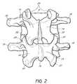
- FIG. 2is a schematic posterior elevational view of two lumbar vertebrae
- FIG. 3is a schematic superior elevational view of a lumbar vertebra
- FIG. 4is a schematic lateral elevational view of a portion of the lumbar spine with spinal nerves in the intervertebral foramina;
- FIG. 5is a schematic transverse cross-sectional view of a spine with nerve impingement by a vertebral disc
- FIG. 6depicts the spine from FIG. 5 with one embodiment of the invention placed in the intervertebral foramen;
- FIG. 7illustrates one embodiment of the invention comprising a cylindrical tubular body
- FIG. 8is another embodiment of the invention comprising a curved tubular body
- FIG. 9is another embodiment of the invention comprising a tapered tubular body
- FIG. 10is another embodiment of the invention comprising a dual-flared tubular body
- FIG. 11depicts another embodiment comprising a tubular body having a triangular outer cross section with a circular lumen
- FIG. 12is a cross sectional view through one embodiment of the invention with rounded edges
- FIG. 13is a cross sectional view through another embodiment of the invention having complementary edges
- FIG. 14is a cross sectional view through another embodiment of the invention having radially outward lipped edges;
- FIG. 15is a cross sectional view through another embodiment of the invention having interlocking edges
- FIGS. 16A and 16Bare oblique elevational views of one embodiment of the invention with a locking element
- FIG. 17illustrates one embodiment of the device having a flange
- FIG. 18depicts one embodiment of the device having a living hinge
- FIGS. 19A and 19Ba neuroprotective device with a spacer
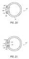
- FIG. 20is a cross sectional view of one embodiment of the invention comprising an interlocking spacer and device
- FIG. 21is a cross sectional view of another embodiment of the invention comprising an interlocking spacer and device
- FIGS. 22A and 22Bare oblique elevational views of a tapered spacer and a device with a widened gap region
- FIGS. 23 and 24depict another embodiment comprising a spiral device.
- the present inventionrelates to a treatment for conditions of the spine.
- the treatmentallows the patient to maintain mobility at the treated portion of the spine, unlike traditional spine surgeries or implanted spinal hardware.
- certain embodimentsallow restoration and/or protection of the neural space by mechanically alleviating or reducing the pressure exerted onto neural structures which may reduce or eliminate pain associated with nerve impingement.
- the deviceshields nerves from compression by surrounding structures that may cause pain.
- the deviceprevents the development of postoperative adhesions or scar tissue between a patient's spinal nerves and other spinal tissues by providing an intervening barrier.
- An embodiment of the inventionmay also be used to protect other structures in neurovascular bundles, including blood vessels and/or lymphatic ducts.
- An embodiment of the inventionmay also be used as an adjunct to discectomy procedures. If the disc re-herniates, the device may provide protection against disc material that may impinge on spinal nerves.
- the vertebral column 2comprises a series of alternating vertebrae 4 and fibrous discs 6 that provide axial support and movement to the upper portions of the body.
- the vertebral column 2typically comprises thirty-three vertebrae 4 , with seven cervical (C1-C7), twelve thoracic (T1-T12), five lumbar (L1-15), five fused sacral (S1-S5) and four fused coccygeal vertebrae 4 .
- Each vertebra 4includes an anterior body 8 and a posterior arch 10 .
- the posterior arch 10comprises two pedicles 12 and two laminae 14 that join posteriorly to form a spinous process 16 .
- FIG. 3depicts the spinal canal 24 that contains the spinal cord (not shown) and is surrounded by the pedicles 12 and laminae 14 .
- the pedicles 12 of each pair of adjacent vertebrae 4form an intervertebral foramen 26 .
- FIG. 4depicts a portion of the vertebral column 2 with spinal nerves 28 exiting from the intervertebral foramina 26 formed by the pedicles 12 of adjacent vertebrae 4 .
- FIG. 5depicts a transverse cross-sectional view of the vertebral column 2 through the intervertebral foramina 26 wherein the vertebral disc 6 has a herniation or bulge 30 posteriorly on one side and has impinged a spinal nerve root 28 exiting the spinal cord 32 .
- a neuroprotective device 34By placing a neuroprotective device 34 in the affected intervertebral foramen 26 , as illustrated in FIG.
- the device 34is able to relieve pressure exerted on the nerve root 28 by the bulge 30 in the vertebral disc 6 and may reduce the inflammation and pain associated with nerve impingement.
- the device 34may also protect the nerve root 28 from postsurgical adhesions or scar tissue that develop from other spinal surgeries. Postsurgical adhesions or scar tissue may also cause nerve impingement or nerve irritation.
- the neuroprotective device 36comprises a tubular body 38 with a lumen 40 and a longitudinal seam or opening 42 along the longitudinal length 44 of the tubular body 38 .
- the tubular body 38comprises a stent structure.
- the tubular body 38has a first end 46 , a second end 48 , an abluminal surface 50 , a luminal surface 52 , an outer diameter 54 , an inner diameter 56 , a first edge 58 and a second edge 60 about the longitudinal opening 42 .
- the device 36has an outer diameter 54 in the range of about 0.5 mm to about 10 mm, and preferably about 3 mm to about 5 mm.
- the inner diameter 56 of the device 36is in range of about 0.4 mm to about 9.9 mm, and preferably about 2 mm to about 4 mm.
- the neuroprotective device 36may have a generally linear configuration as shown in FIG. 7 , or it may have a non-linear configuration.
- FIG. 8depicts one embodiment of a non-linear configuration comprising a curved tubular body 62 .
- a non-linear devicemay be better fitted to a particular patient's anatomy than a device 36 with a linear configuration.
- the device 36has a generally cylindrical shape, as depicted in FIG. 7 , with a generally constant outer diameter 54 and inner diameter 56 along its longitudinal length 44 . In other embodiments, either or both the outer diameter 54 and the inner diameter 56 of the device 36 can vary along the longitudinal length 44 .
- FIG. 9depicts one embodiment of the device 64 having a tapered outer diameter where the outer diameter 66 at the first end 46 is smaller than the outer diameter 68 at the second end 48 . Such a configuration may facilitate insertion of the device 64 into the foramen 26 .
- the inner diameters 70 , 72 at the first end 46 and second end 48 , respectively, of the device 64may or may not change proportionately with the change in the outer diameters 66 , 68 .
- the wall thickness 74 of the deviceneed not be constant at any point along the device 64 . In some embodiments of the invention, the wall thickness 74 may be varied to provide augment the structural resistance to directional deformation forces that may affect the protected nerve 28 .
- the tubular body 76comprises a middle section 78 having an outer diameter 80 that is less than the outer diameters 82 , 84 at the first end 86 and second end 88 of the tubular body 76 , respectively.
- the flared first and second ends 86 , 88may assist in stabilizing the position of the tubular body 76 by resisting slippage or displacement of the tubular body 76 out of the foramen 26 .
- the general cross sectional shape of the device 36 depicted in FIG. 7is a circular C-shape
- the cross-sectional shape of the device 36may be any of a variety of shapes, including triangular, oval, square, polygonal, trapezoid or any other shape.
- the general cross-sectional shape of the devicemay vary along the longitudinal length of the device and the general cross-sectional shape of the outer diameter and the lumen need not be the same.
- FIG. 11depicts a neuroprotective device 90 having a linear configuration with a triangular outer cross section 92 and a lumen 94 having a circular cross section.
- the first and second edges 58 , 60 of the tubular body 38may be squared or flat, as illustrated in FIG. 7 , but in other embodiments, the first and second edges of the tubular body may have any of a variety of configurations.
- FIG. 12depicts a cross sectional view of one embodiment of the invention wherein the tubular body 96 comprises rounded first and second edges 98 , 100 . The configuration need not be the same for the first and second edges 98 , 100 and may also change along the longitudinal length of the tubular body 96 .
- the design and materials of the tubular body 96are selected such that the tubular body 96 is configured to resist narrowing or closure of the longitudinal seam or opening 42 along the length of the tubular body 96 after implantation.
- the tubular body 96is configured to partially bend after implantation such that the first and second edges 98 , 100 of the tubular body 96 contact along at least a portion of the longitudinal length of the seam or opening 42 .
- the first and second edges 102 , 104 of the tubular body 106have complementary shapes that are capable of forming an interfit to resist further collapse or slippage between the first and second edges 102 , 104 .
- FIG. 13illustrates one embodiment wherein the second edge 104 of the device comprises a Y-shaped cross sectional configuration adapted to accept a pointed first edge 102 of the tubular body 106 .
- the Y-shaped cross section of the second edge 104provides a broader contact surface area to reduce the risk that the first edge 102 may slip past the second edge 104 as compressive forces causes narrowing or closure of the longitudinal opening 42 .
- first and/or second edges 102 , 104 of the tubular body 96may be configured with any of a variety of complementary configurations to reduce the risk of slippage between the edges and/or to resist collapse of the tubular body 96 generally.
- a locking interfitmay also be formed by the first and second edges of the tubular body.
- the first edge 110 and second edge 112 of the tubular body 108each comprise a lip 114 , 116 extending radially outward from the respective edges 110 , 112 that provide a larger and more stable contact surface area for each edge 110 , 112 .
- the width of the lips 114 , 116also reduces the risk that either edge 110 , 112 can slip past the other edge 110 , 112 .
- the lips 114 , 116need not be present along the entire length of the longitudinal opening 42 .
- paired openingsmay be provided in the lips 114 , 116 to allow the lips 114 , 116 to be fastened together with a screw or other fastener.
- FIG. 15depicts one embodiment of the invention comprising an interlocking complementary fit between the first edge 118 and second edge 120 of the tubular body 122 , with the first edge 118 having a male member 124 and the second edge 120 having a female receiving site 126 for the male member 124 .
- FIGS. 16A and 16Bdepict an embodiment of the invention with an interlockable complementary fit between the first edge 128 and second edge 130 of the tubular body 132 , comprising complementary alternating protrusions 134 configured with longitudinally oriented lumens 136 that align when the protrusions 134 are in contact with one another.
- a separate locking element 138may be inserted through the lumen to resist separation of the edges 128 , 130 .
- the tubular bodyhas two longitudinal portions separated by two longitudinal seams, each portion capable of forming an interlocking fit with the other portion.
- one or more flanges 140may be provided along the abluminal surface 50 of the device 36 .
- Each flange 140may occupy a portion or all of a given circumference of the tubular body 38 .
- the flangemay be oriented differently to allow attachment of the device 36 onto the transverse process or other structure of a vertebra 4 .
- Each flange 140may be located anywhere along the length of the tubular body 38 , but is preferably located at the position which provides the expected insertion depth of the tubular body 38 into the foramen 26 . Thus, the flange 140 may assist the surgeon in positioning the tubular body 38 in a desired location within the foramen 26 .
- the flange 140comprises one or more through openings 142 capable of accepting a fixation component, such as a bone screw, for attaching the device 36 to a bony surface.
- the flange 140comprises a material or configuration that provides some malleability to allow the flange 140 to at least partially conform the flange 140 to the bony structure to which it is attached.
- the flange 140 alone, without any openings,is sufficient to maintain the device 36 at the desired location.
- the tubular body 38 of the device 36may have one or more regions 144 of reduced wall thickness to facilitate at least partial narrowing or widening of the longitudinal opening 42 .
- the region or regions of reduced wall thicknesscomprise a full-length longitudinal hinge or groove 144 on the abluminal surface 50 and/or luminal surface 52 of the tubular body 38 that is generally about 180 degrees opposite the position of the longitudinal opening 42 .
- the region or regions of reduced wall thicknessoccupy only a portion of the longitudinal length of the tubular body 38 and/or are located at a position less about 180 degrees from the longitudinal opening 42 of the tubular body 38 .
- the tubular body 38comprises a mechanical hinge along the length of the device 36 to allow at least partial opening and closing of the longitudinal opening 42 .
- the device 36further comprises a spacer 146 that may be inserted into the longitudinal opening 42 of the device 36 to increase size of the lumen 40 and provide more space around the nerve root 28 .
- a spacer 146may be inserted after the device 36 is positioned in the intervertebral foramen 26 .
- the spacer 146comprises an elongate body 148 generally having an H-shaped cross section, an outer height 150 , an inter-edge height 152 , an inner height 154 , a first edge groove 156 and a second edge groove 158 , an insertion end 160 and a trailing end 162 .
- the inter-edge height 152 of the spacer 146determines the separation between the edges 58 , 60 of the device 36 .
- the outer height 150 of the elongate body 148is about equal to the height of the inner height 154 of the elongate body 148 .
- the inner height 154is different from the outer height 150 , preferably having a reduced inner height 154 to decrease the amount volume taken by the spacer 146 in the lumen 40 of the device 36 .
- first edge groove 156 and/or the second edge groove 158is configured with a cross-sectional configuration that is complementary to the cross sectional shape of the first edge 58 and/or second edge 60 of the device 36 , respectively, to improve the fit of the spacer 146 to the device 36 .
- the complementary configuration of the device 36 and spacer 146is an interlocking configuration.
- FIG. 20depicts one embodiment of an interlocking configuration of the device 36 and spacer 166 comprising protrusions 168 on the abluminal surface 50 of the device 36 and complementary tracks 170 on the spacer 166 .
- FIG. 21depicts another embodiment where the male member 124 on the first edge 118 of the device 122 are capable of forming a snapfit with the second edge 120 of the device 120 , or optionally a snapfit or sliding interlocking fit with a spacer 172 having a female receiving site 174 complementary to the male member 124 of the first edge 118 of the device 122 and a spacer male member 176 that is complementary to the female receiving site 126 on the second edge 120 of the device 122 .
- a spacer male member 176that is complementary to the female receiving site 126 on the second edge 120 of the device 122 .
- any of a variety of interlocking configurations and sites between the device 122 and spacer 172may be used for the invention.
- the inter-edge height 152 of the spacer 146is tapered at least at the insertion end 160 of the spacer 146 to facilitate a gradual separation of the first and second edges 58 , 60 of the device 36 as the spacer 146 is inserted into the longitudinal seam 42 .
- at least a portion of the longitudinal seam 42 at second end 48 of the device 36has a tapered gap section 178 to facilitate insertion of the spacer 146 into the longitudinal seam 42 .
- FIG. 23depicts another embodiment of the invention comprising a spiral or coiled neuroprotective device 180 having an insertion end 182 and a trailing end 184 and adapted for insertion into the intervertebral foramen 26 .
- the spacing 186 between each spiral 188 of the device 180is configured to allow the isolated nerve root 28 to pass through the spacing 186 as the device 180 is twisted into the foramen 26 .
- FIG. 24illustrates how the device 180 is inserted into a foramen 26 and over the nerve root 28 .
- the turn radius of the spirals 188 and the spacing 188 between each spiral 188need not be uniform along the length of the device 180 . In the preferred embodiment of the invention, the turn radius of the spirals at the insertion end 182 and/or trailing end 184 of the device 180 is larger to help maintain the device 180 in the intervertebral foramen 26 .
- the device 36may comprise a polymer such as polyetheretherketone (PEEK), polyetherketoneketone (PEKK), or a fluropolymer, an elastomer, a ceramic such as zirconia, alumina or silicon nitride, a metal such as titanium, a titanium alloy, cobalt chromium or stainless steel, or a combination of these materials.
- the devicecomprises a metallic frame embedded in a tubular polymer structure.
- radioopaque markersmay be embedded in or on the device 36 to assist in placement or monitoring of the device 36 under radiographic visualization.
- the device 36may comprise a bioabsorbable or bioresorbable material that is known in the art. By selecting a particular configuration and material for the tubular body 38 , one skilled in the art can adapt the device 36 to have the desired resiliency.
- the outer surface 50 of the device 36may be further configured to provide one or more characteristics.
- at least a portion of the abluminal surface 50 of the tubular body 38comprises a porous layer for allowing bone ingrowth into the device 36 .
- the porous layermay be formed by the application of sintered beads or plasma sprayed material onto the outer surface of the device 36 .
- the abluminal surface 50may be laser treated or mechanically roughened to provide an irregular surface, or formed with protrusions or knurls, to resist sliding contact with bony surfaces contacting the device 36 .
- the luminal surface 50may be polished or micropolished to facilitate insertion of the device into the foramen 26 .
- a polished device 36may rely on one or more flanges 118 to secure the device 36 in the foramen 26 .
- the inner surface 52 of the device 36may be similar treated as the outer surface, but in the preferred embodiment the inner surface 52 is polished or micropolished to reduce the risk of damage to the neural structures within the lumen 40 of the device 36 .
- the device 36may also further comprise at least one drug-eluting region loaded with one or more treatment agents.
- the treatment agentsmay be any of a variety of treatment agents known in the art and include but are not limited to anti-bacterial agents, anti-inflammatory agents, anti-proliferative agents
- the intervertebral foramen 26is accessed by an open procedure as is known by those with skill in the art.
- the vertebrae 4 forming the foramen 26are distracted along their longitudinal axis.
- the neural structure 28is isolated and the device 36 is passed over the neural structure 28 through the longitudinal seam 42 within the intervertebral foramen 26 .
- the placement of the device 36may be performed in conjunction with orthopedic spine procedures, if any.
- the device 36is optionally attached to one or more vertebrae 4 if the device 36 has at least one flange 118 with an attachment opening 120 .
- the distraction force, if any,is removed from the vertebrae 4 and the surgical site is closed.
- the intervertebral foramen 26is accessed in a minimally invasive manner.
- injection of radio-opaque dyeis used to identify the vertebrae 4 , foramen 26 and neural structures 28 .
- positioning markersmay be placed about the vertebral column 2 to assist in localizing the spinal structures.
- the vertebrae 4 forming the foramen 26are optionally distracted along their longitudinal axis to enlarge the foramen 26 during the procedure.
- the neural structure 28is isolated and the device 36 is passed over the neural structure 28 through the longitudinal opening 42 within the intervertebral foramen 26 in conjunction with any other orthopedic spine procedures, if any.
- the device 36is optionally attached to one or more vertebrae 4 if the device 36 has at least one flange 118 with an attachment opening 120 .
- the distraction force, if any,is removed from the vertebrae 4 and the surgical site is closed.
Landscapes
- Health & Medical Sciences (AREA)
- Life Sciences & Earth Sciences (AREA)
- Engineering & Computer Science (AREA)
- Biomedical Technology (AREA)
- Orthopedic Medicine & Surgery (AREA)
- Public Health (AREA)
- Veterinary Medicine (AREA)
- Heart & Thoracic Surgery (AREA)
- Animal Behavior & Ethology (AREA)
- General Health & Medical Sciences (AREA)
- Surgery (AREA)
- Neurology (AREA)
- Cardiology (AREA)
- Oral & Maxillofacial Surgery (AREA)
- Transplantation (AREA)
- Vascular Medicine (AREA)
- Nuclear Medicine, Radiotherapy & Molecular Imaging (AREA)
- Molecular Biology (AREA)
- Medical Informatics (AREA)
- Gastroenterology & Hepatology (AREA)
- Pulmonology (AREA)
- Prostheses (AREA)
- Surgical Instruments (AREA)
- Materials For Medical Uses (AREA)
Abstract
Description
Claims (7)
Priority Applications (6)
| Application Number | Priority Date | Filing Date | Title |
|---|---|---|---|
| US11/055,162US7744612B2 (en) | 2004-02-10 | 2005-02-10 | System and method for protecting neurovascular structures |
| US12/782,002US8500763B2 (en) | 2004-02-10 | 2010-05-18 | System and method for protecting neurovascular structures |
| US13/937,438US9072608B2 (en) | 2004-02-10 | 2013-07-09 | System and method for protecting neurovascular structures |
| US14/624,340US9693870B2 (en) | 2004-02-10 | 2015-02-17 | System and method for protecting neurovascular structures |
| US15/591,550US20170239071A1 (en) | 2004-02-10 | 2017-05-10 | System and method for protecting neurovascular structures |
| US16/860,480US11554032B2 (en) | 2004-02-10 | 2020-04-28 | System and method for protecting neurovascular structures |
Applications Claiming Priority (2)
| Application Number | Priority Date | Filing Date | Title |
|---|---|---|---|
| US54321204P | 2004-02-10 | 2004-02-10 | |
| US11/055,162US7744612B2 (en) | 2004-02-10 | 2005-02-10 | System and method for protecting neurovascular structures |
Related Child Applications (1)
| Application Number | Title | Priority Date | Filing Date |
|---|---|---|---|
| US12/782,002DivisionUS8500763B2 (en) | 2004-02-10 | 2010-05-18 | System and method for protecting neurovascular structures |
Publications (2)
| Publication Number | Publication Date |
|---|---|
| US20050192574A1 US20050192574A1 (en) | 2005-09-01 |
| US7744612B2true US7744612B2 (en) | 2010-06-29 |
Family
ID=34860394
Family Applications (6)
| Application Number | Title | Priority Date | Filing Date |
|---|---|---|---|
| US11/055,162Active2029-01-30US7744612B2 (en) | 2004-02-10 | 2005-02-10 | System and method for protecting neurovascular structures |
| US12/782,002Expired - Fee RelatedUS8500763B2 (en) | 2004-02-10 | 2010-05-18 | System and method for protecting neurovascular structures |
| US13/937,438Expired - LifetimeUS9072608B2 (en) | 2004-02-10 | 2013-07-09 | System and method for protecting neurovascular structures |
| US14/624,340Expired - Fee RelatedUS9693870B2 (en) | 2004-02-10 | 2015-02-17 | System and method for protecting neurovascular structures |
| US15/591,550AbandonedUS20170239071A1 (en) | 2004-02-10 | 2017-05-10 | System and method for protecting neurovascular structures |
| US16/860,480Active2026-05-15US11554032B2 (en) | 2004-02-10 | 2020-04-28 | System and method for protecting neurovascular structures |
Family Applications After (5)
| Application Number | Title | Priority Date | Filing Date |
|---|---|---|---|
| US12/782,002Expired - Fee RelatedUS8500763B2 (en) | 2004-02-10 | 2010-05-18 | System and method for protecting neurovascular structures |
| US13/937,438Expired - LifetimeUS9072608B2 (en) | 2004-02-10 | 2013-07-09 | System and method for protecting neurovascular structures |
| US14/624,340Expired - Fee RelatedUS9693870B2 (en) | 2004-02-10 | 2015-02-17 | System and method for protecting neurovascular structures |
| US15/591,550AbandonedUS20170239071A1 (en) | 2004-02-10 | 2017-05-10 | System and method for protecting neurovascular structures |
| US16/860,480Active2026-05-15US11554032B2 (en) | 2004-02-10 | 2020-04-28 | System and method for protecting neurovascular structures |
Country Status (6)
| Country | Link |
|---|---|
| US (6) | US7744612B2 (en) |
| EP (1) | EP1761177B1 (en) |
| JP (1) | JP4594332B2 (en) |
| AU (2) | AU2005211797B2 (en) |
| CA (2) | CA2555407C (en) |
| WO (1) | WO2005077113A2 (en) |
Cited By (48)
| Publication number | Priority date | Publication date | Assignee | Title |
|---|---|---|---|---|
| US20070083200A1 (en)* | 2005-09-23 | 2007-04-12 | Gittings Darin C | Spinal stabilization systems and methods |
| US20080097486A1 (en)* | 2004-10-06 | 2008-04-24 | Ross Anthony C | Systems and Methods for Direct Restoration of Foraminal Volume |
| US20100168872A1 (en)* | 2007-09-04 | 2010-07-01 | Ucl. Business Plc | Biomaterial scaffolds for controlled tissue growth |
| US20110015656A1 (en)* | 2007-08-14 | 2011-01-20 | Eduardo Gonzalez-Hernandez | Device for assisting in flexor tendon repair and rehabilitation |
| US8343189B2 (en) | 2007-09-25 | 2013-01-01 | Zyga Technology, Inc. | Method and apparatus for facet joint stabilization |
| US8394125B2 (en) | 2009-07-24 | 2013-03-12 | Zyga Technology, Inc. | Systems and methods for facet joint treatment |
| US8403991B2 (en) | 2005-05-06 | 2013-03-26 | Titan Spine Llc | Implant with critical ratio of load bearing surface area to central opening area |
| US8435302B2 (en) | 2005-05-06 | 2013-05-07 | Titan Spine, Llc | Instruments and interbody spinal implants enhancing disc space distraction |
| US8480749B2 (en) | 2005-05-06 | 2013-07-09 | Titan Spine, Llc | Friction fit and vertebral endplate-preserving spinal implant |
| US8496710B2 (en) | 2005-05-06 | 2013-07-30 | Titan Spine, Llc | Interbody spinal implant having a roughened surface topography |
| US8545568B2 (en) | 2005-05-06 | 2013-10-01 | Titan Spine, Llc | Method of using instruments and interbody spinal implants to enhance distraction |
| US8551176B2 (en) | 2005-05-06 | 2013-10-08 | Titan Spine, Llc | Spinal implant having a passage for enhancing contact between bone graft material and cortical endplate bone |
| US8551105B2 (en) | 2007-04-25 | 2013-10-08 | Spinal Elements, Inc. | Spinal implant distractor/inserter |
| US8562684B2 (en) | 2005-05-06 | 2013-10-22 | Titan Spine, Llc | Endplate-preserving spinal implant with an integration plate having a roughened surface topography |
| US8562685B2 (en) | 2005-05-06 | 2013-10-22 | Titan Spine, Llc | Spinal implant and integration plate for optimizing vertebral endplate contact load-bearing edges |
| US8585765B2 (en) | 2005-05-06 | 2013-11-19 | Titan Spine, Llc | Endplate-preserving spinal implant having a raised expulsion-resistant edge |
| US8585766B2 (en) | 2005-05-06 | 2013-11-19 | Titan Spine, Llc | Endplate-preserving spinal implant with an integration plate having durable connectors |
| US8585767B2 (en) | 2005-05-06 | 2013-11-19 | Titan Spine, Llc | Endplate-preserving spinal implant with an integration plate having durable connectors |
| US8591590B2 (en) | 2005-05-06 | 2013-11-26 | Titan Spine, Llc | Spinal implant having a transverse aperture |
| US8617248B2 (en) | 2005-05-06 | 2013-12-31 | Titan Spine, Llc | Spinal implant having variable ratios of the integration surface area to the axial passage area |
| US8663293B2 (en) | 2010-06-15 | 2014-03-04 | Zyga Technology, Inc. | Systems and methods for facet joint treatment |
| US8696707B2 (en) | 2005-03-08 | 2014-04-15 | Zyga Technology, Inc. | Facet joint stabilization |
| US20140114133A1 (en)* | 2012-10-23 | 2014-04-24 | Amendia, Inc. | Dilator delivered nerve shield |
| US8758442B2 (en) | 2005-05-06 | 2014-06-24 | Titan Spine, Llc | Composite implants having integration surfaces composed of a regular repeating pattern |
| US8758443B2 (en) | 2005-05-06 | 2014-06-24 | Titan Spine, Llc | Implants with integration surfaces having regular repeating surface patterns |
| US8814939B2 (en) | 2005-05-06 | 2014-08-26 | Titan Spine, Llc | Implants having three distinct surfaces |
| US8992619B2 (en) | 2011-11-01 | 2015-03-31 | Titan Spine, Llc | Microstructured implant surfaces |
| US8992622B2 (en) | 2005-05-06 | 2015-03-31 | Titan Spine, Llc | Interbody spinal implant having a roughened surface topography |
| US9072608B2 (en) | 2004-02-10 | 2015-07-07 | Spinal Elements, Inc. | System and method for protecting neurovascular structures |
| US9125756B2 (en) | 2005-05-06 | 2015-09-08 | Titan Spine, Llc | Processes for producing regular repeating patterns on surfaces of interbody devices |
| US9168147B2 (en) | 2005-05-06 | 2015-10-27 | Titan Spine, Llc | Self-deploying locking screw retention device |
| US9233006B2 (en) | 2010-06-15 | 2016-01-12 | Zyga Technology, Inc. | Systems and methods for facet joint treatment |
| US9498349B2 (en) | 2012-10-09 | 2016-11-22 | Titan Spine, Llc | Expandable spinal implant with expansion wedge and anchor |
| US9615935B2 (en) | 2014-01-30 | 2017-04-11 | Titan Spine, Llc | Thermally activated shape memory spring assemblies for implant expansion |
| US9642721B2 (en) | 2012-10-02 | 2017-05-09 | Titan Spine, Llc | Implants with self-deploying anchors |
| US9655745B2 (en) | 2005-05-06 | 2017-05-23 | Titan Spine, Llc | Methods for manufacturing implants having integration surfaces |
| US9833328B2 (en) | 2010-06-15 | 2017-12-05 | Zyga Technology | System and methods for facet joint treatment |
| US9848995B2 (en) | 2012-03-20 | 2017-12-26 | Titan Spine Llc | Process for fabricating bioactive vertebral endplate bone-contacting surfaces on a spinal implant |
| US10687797B2 (en) | 2008-12-18 | 2020-06-23 | Howmedica Osteonics Corp. | Lateral access system for the lumbar spine |
| US10973658B2 (en) | 2017-11-27 | 2021-04-13 | Titan Spine, Inc. | Rotating implant and associated instrumentation |
| US11096796B2 (en) | 2005-05-06 | 2021-08-24 | Titan Spine, Llc | Interbody spinal implant having a roughened surface topography on one or more internal surfaces |
| US11135070B2 (en) | 2018-02-14 | 2021-10-05 | Titan Spine, Inc. | Modular adjustable corpectomy cage |
| US11166800B2 (en)* | 2018-04-12 | 2021-11-09 | Axogen Corporation | Tissue grafts with pre-made attachment points |
| US11166709B2 (en) | 2016-08-23 | 2021-11-09 | Stryker European Operations Holdings Llc | Instrumentation and methods for the implantation of spinal implants |
| US11191532B2 (en) | 2018-03-30 | 2021-12-07 | Stryker European Operations Holdings Llc | Lateral access retractor and core insertion |
| US11273058B2 (en) | 2019-05-07 | 2022-03-15 | Spinal Elements, Inc. | Cervical plate and inserter |
| US11413029B2 (en) | 2018-10-24 | 2022-08-16 | Stryker European Operations Holdings Llc | Anterior to psoas instrumentation |
| US11564674B2 (en) | 2019-11-27 | 2023-01-31 | K2M, Inc. | Lateral access system and method of use |
Families Citing this family (42)
| Publication number | Priority date | Publication date | Assignee | Title |
|---|---|---|---|---|
| US7588590B2 (en) | 2003-12-10 | 2009-09-15 | Facet Solutions, Inc | Spinal facet implant with spherical implant apposition surface and bone bed and methods of use |
| US8029548B2 (en) | 2008-05-05 | 2011-10-04 | Warsaw Orthopedic, Inc. | Flexible spinal stabilization element and system |
| US8562649B2 (en) | 2004-02-17 | 2013-10-22 | Gmedelaware 2 Llc | System and method for multiple level facet joint arthroplasty and fusion |
| US8333789B2 (en) | 2007-01-10 | 2012-12-18 | Gmedelaware 2 Llc | Facet joint replacement |
| US7507242B2 (en) | 2004-06-02 | 2009-03-24 | Facet Solutions | Surgical measurement and resection framework |
| US7935134B2 (en) | 2004-10-20 | 2011-05-03 | Exactech, Inc. | Systems and methods for stabilization of bone structures |
| US8025680B2 (en) | 2004-10-20 | 2011-09-27 | Exactech, Inc. | Systems and methods for posterior dynamic stabilization of the spine |
| US8267969B2 (en) | 2004-10-20 | 2012-09-18 | Exactech, Inc. | Screw systems and methods for use in stabilization of bone structures |
| US8162985B2 (en) | 2004-10-20 | 2012-04-24 | The Board Of Trustees Of The Leland Stanford Junior University | Systems and methods for posterior dynamic stabilization of the spine |
| US8226690B2 (en) | 2005-07-22 | 2012-07-24 | The Board Of Trustees Of The Leland Stanford Junior University | Systems and methods for stabilization of bone structures |
| US9055981B2 (en)* | 2004-10-25 | 2015-06-16 | Lanx, Inc. | Spinal implants and methods |
| US8241330B2 (en)* | 2007-01-11 | 2012-08-14 | Lanx, Inc. | Spinous process implants and associated methods |
| US20060178554A1 (en)* | 2005-02-04 | 2006-08-10 | Mandel Shlomo S | Nerve protection barrier |
| US20060254599A1 (en)* | 2005-05-10 | 2006-11-16 | Levin Bruce H | Intervention techniques for post-laminectomy syndrome and other spinal disorders |
| US8523865B2 (en) | 2005-07-22 | 2013-09-03 | Exactech, Inc. | Tissue splitter |
| US7533672B2 (en) | 2005-09-06 | 2009-05-19 | Synthes Usa, Llc | Methods and apparatus for vascular protection in spinal surgery |
| US20070135814A1 (en)* | 2005-12-12 | 2007-06-14 | Sdgi Holdings, Inc. | Facet spacer |
| US20070250166A1 (en)* | 2006-04-25 | 2007-10-25 | Sdgi Holdings, Inc. | Facet fusion implants and methods of use |
| US8142355B2 (en)* | 2006-09-25 | 2012-03-27 | Spinal Elements, Inc. | Surgical tissue retractor |
| US20080161920A1 (en)* | 2006-10-03 | 2008-07-03 | Warsaw Orthopedic, Inc. | Dynamizing Interbody Implant and Methods for Stabilizing Vertebral Members |
| US8092533B2 (en)* | 2006-10-03 | 2012-01-10 | Warsaw Orthopedic, Inc. | Dynamic devices and methods for stabilizing vertebral members |
| US20080161810A1 (en)* | 2006-10-18 | 2008-07-03 | Warsaw Orthopedic, Inc. | Guide and Cutter for Contouring Facet Joints and Methods of Use |
| US8096996B2 (en) | 2007-03-20 | 2012-01-17 | Exactech, Inc. | Rod reducer |
| US9247968B2 (en)* | 2007-01-11 | 2016-02-02 | Lanx, Inc. | Spinous process implants and associated methods |
| US8382801B2 (en)* | 2007-01-11 | 2013-02-26 | Lanx, Inc. | Spinous process implants, instruments, and methods |
| US9265532B2 (en)* | 2007-01-11 | 2016-02-23 | Lanx, Inc. | Interspinous implants and methods |
| US8109975B2 (en)* | 2007-01-30 | 2012-02-07 | Warsaw Orthopedic, Inc. | Collar bore configuration for dynamic spinal stabilization assembly |
| US8454622B2 (en)* | 2007-04-25 | 2013-06-04 | Spinal Elements, Inc. | Spinal implant distractor/inserter |
| US20110172708A1 (en)* | 2007-06-22 | 2011-07-14 | Simpirica Spine, Inc. | Methods and systems for increasing the bending stiffness of a spinal segment with elongation limit |
| WO2009026530A1 (en)* | 2007-08-23 | 2009-02-26 | Cardious, Inc. | Conduit protector |
| US8864770B2 (en)* | 2008-03-12 | 2014-10-21 | Spinal Elements, Inc. | Offset opposing arm spinal implant distractor/inserter |
| US9017384B2 (en)* | 2008-05-13 | 2015-04-28 | Stryker Spine | Composite spinal rod |
| CA2745462C (en)* | 2008-12-31 | 2014-07-15 | Kci Licensing, Inc. | Tissue roll scaffolds |
| US20100256761A1 (en)* | 2009-04-03 | 2010-10-07 | Komistek Richard D | Minimally invasive total spine implant |
| WO2012040206A1 (en) | 2010-09-20 | 2012-03-29 | Synthes Usa, Llc | Spinal access retractor |
| US11812923B2 (en) | 2011-10-07 | 2023-11-14 | Alan Villavicencio | Spinal fixation device |
| US9408596B2 (en) | 2013-03-11 | 2016-08-09 | Spinal Elements, Inc. | Method of using a surgical tissue retractor |
| US9662002B2 (en)* | 2014-07-10 | 2017-05-30 | Amendia, Inc. | Endoscopic portal protective shield assembly |
| EP3190982B1 (en) | 2014-09-10 | 2020-06-24 | Spinal Elements, Inc. | Retractor |
| US20160166284A1 (en)* | 2014-12-16 | 2016-06-16 | Oxford Performance Materials, Inc. | Methods and Systems For Local Administration of Therapeutics |
| EP3426163A4 (en) | 2016-03-09 | 2019-12-11 | Spinal Elements Inc. | RETRACTOR |
| JPWO2019054407A1 (en)* | 2017-09-15 | 2020-10-29 | 東洋紡株式会社 | Neuroprotective material |
Citations (25)
| Publication number | Priority date | Publication date | Assignee | Title |
|---|---|---|---|---|
| US4013078A (en) | 1974-11-25 | 1977-03-22 | Feild James Rodney | Intervertebral protector means |
| US4534349A (en)* | 1983-02-02 | 1985-08-13 | Minnesota Mining And Manufacturing Company | Absorbable sutureless nerve repair device |
| US4573471A (en)* | 1984-07-09 | 1986-03-04 | Rudner Merritt A | Prosthetic apparatus for surgical anastomosis |
| US4662884A (en)* | 1984-04-25 | 1987-05-05 | University Of Utah Research Foundation | Prostheses and methods for promoting nerve regeneration |
| US4669474A (en)* | 1984-01-12 | 1987-06-02 | Minnesota Mining And Manufacturing Company | Absorbable nerve repair device and method |
| US4778467A (en)* | 1984-04-25 | 1988-10-18 | The University Of Utah | Prostheses and methods for promoting nerve regeneration and for inhibiting the formation of neuromas |
| US4870966A (en)* | 1988-02-01 | 1989-10-03 | American Cyanamid Company | Bioabsorbable surgical device for treating nerve defects |
| US4883618A (en)* | 1983-02-02 | 1989-11-28 | Minnesota Mining And Manufacturing Company | Absorbable nerve repair device and method |
| US5147399A (en)* | 1988-02-01 | 1992-09-15 | Dellon Arnold L | Method of treating nerve defects through use of a bioabsorbable surgical device |
| US5400784A (en) | 1993-10-15 | 1995-03-28 | Case Western Reserve University | Slowly penetrating inter-fascicular nerve cuff electrode and method of using |
| US5487756A (en) | 1994-12-23 | 1996-01-30 | Simon Fraser University | Implantable cuff having improved closure |
| US6102921A (en)* | 1990-12-21 | 2000-08-15 | University Of New Mexico | Nerve anastomosis sling and method |
| US6106558A (en)* | 1997-09-15 | 2000-08-22 | Applied Medical Research, Inc. | Neuro decompression device |
| GB2366736A (en) | 2000-06-28 | 2002-03-20 | Geistlich Soehne Ag | Collagen tubes |
| EP1201256A2 (en) | 2000-10-28 | 2002-05-02 | DEUTSCHE INSTITUTE FÜR TEXTIL- UND FASERFORSCHUNG STUTTGART Stiftung des öffentlichen Rechts | Bioresorbable nerve guidance channels |
| EP1201202A1 (en) | 1999-07-07 | 2002-05-02 | Tapic International Co., Ltd. | Artificial neural tube |
| WO2002096300A1 (en) | 2001-05-25 | 2002-12-05 | Hb Medicals Corporation | Nerve anastomosis device |
| US6600956B2 (en) | 2001-08-21 | 2003-07-29 | Cyberonics, Inc. | Circumneural electrode assembly |
| US20030204259A1 (en)* | 2000-12-13 | 2003-10-30 | Goble E. Marlowe | Multiple facet joint replacement |
| US20040111139A1 (en)* | 2002-12-10 | 2004-06-10 | Mccreery Douglas B. | Apparatus and methods for differential stimulation of nerve fibers |
| US20040199187A1 (en)* | 2003-04-02 | 2004-10-07 | Frank Loughran | Nerve protecting tube |
| US20050192574A1 (en)* | 2004-02-10 | 2005-09-01 | Jason Blain | System and method for protecting neurovascular structures |
| US6999819B2 (en)* | 2001-08-31 | 2006-02-14 | Medtronic, Inc. | Implantable medical electrical stimulation lead fixation method and apparatus |
| US20060111768A1 (en)* | 2000-09-26 | 2006-05-25 | Micronet Medical, Inc. | Lead body and method of lead body construction |
| US7054692B1 (en)* | 2001-06-22 | 2006-05-30 | Advanced Bionics Corporation | Fixation device for implantable microdevices |
Family Cites Families (15)
| Publication number | Priority date | Publication date | Assignee | Title |
|---|---|---|---|---|
| GB524528A (en) | 1938-03-22 | 1940-08-08 | Vetreria Italiana Balz | Improvements in or relating to the manufacture of threads of glass or other synthetic material |
| WO1984003035A1 (en)* | 1983-02-02 | 1984-08-16 | Minnesota Mining & Mfg | Absorbable nerve repair device and method |
| CA1335527C (en) | 1988-02-01 | 1995-05-16 | Arnold Lee Dellon | Bioabsorbable surgical device for treating nerve defects |
| JP2748410B2 (en) | 1988-06-24 | 1998-05-06 | 日本電気株式会社 | ImPP program startup method |
| WO1996016612A1 (en)* | 1994-12-02 | 1996-06-06 | Omeros Medical Systems, Inc. | Tendon and ligament repair system |
| US5603720A (en)* | 1995-01-27 | 1997-02-18 | Kieturakis; Maciej J. | Surgical method for use with transluminal dilation catheter |
| US5803904A (en) | 1997-10-28 | 1998-09-08 | Mehdizadeh; Hamid | Nerve root retractor and disc space separator |
| US7621950B1 (en)* | 1999-01-27 | 2009-11-24 | Kyphon Sarl | Expandable intervertebral spacer |
| US6308105B1 (en)* | 1999-07-15 | 2001-10-23 | Medtronic Inc. | Medical electrical stimulation system using an electrode assembly having opposing semi-circular arms |
| US7867186B2 (en)* | 2002-04-08 | 2011-01-11 | Glaukos Corporation | Devices and methods for treatment of ocular disorders |
| US6975907B2 (en)* | 2001-11-13 | 2005-12-13 | Dynamed Systems, Llc | Apparatus and method for repair of spinal cord injury |
| WO2004087256A1 (en)* | 2003-04-02 | 2004-10-14 | Neurostream Technologies Inc. | Implantable nerve signal sensing and stimulation device for treating foot drop and other neurological disorders |
| JP2005000188A (en)* | 2003-06-09 | 2005-01-06 | Olympus Corp | Protective tube and protective tube applicator |
| US7413561B2 (en)* | 2003-08-13 | 2008-08-19 | Medical Components, Inc. | Conduit retaining clip |
| US20060178554A1 (en)* | 2005-02-04 | 2006-08-10 | Mandel Shlomo S | Nerve protection barrier |
- 2005
- 2005-02-10WOPCT/US2005/004511patent/WO2005077113A2/enactiveApplication Filing
- 2005-02-10USUS11/055,162patent/US7744612B2/enactiveActive
- 2005-02-10JPJP2006553298Apatent/JP4594332B2/ennot_activeExpired - Fee Related
- 2005-02-10CACA2555407Apatent/CA2555407C/ennot_activeExpired - Lifetime
- 2005-02-10EPEP05723001.3Apatent/EP1761177B1/ennot_activeExpired - Lifetime
- 2005-02-10CACA2802131Apatent/CA2802131C/ennot_activeExpired - Lifetime
- 2005-02-10AUAU2005211797Apatent/AU2005211797B2/ennot_activeCeased
- 2010
- 2010-05-18USUS12/782,002patent/US8500763B2/ennot_activeExpired - Fee Related
- 2011
- 2011-01-28AUAU2011200370Apatent/AU2011200370B2/ennot_activeCeased
- 2013
- 2013-07-09USUS13/937,438patent/US9072608B2/ennot_activeExpired - Lifetime
- 2015
- 2015-02-17USUS14/624,340patent/US9693870B2/ennot_activeExpired - Fee Related
- 2017
- 2017-05-10USUS15/591,550patent/US20170239071A1/ennot_activeAbandoned
- 2020
- 2020-04-28USUS16/860,480patent/US11554032B2/enactiveActive
Patent Citations (26)
| Publication number | Priority date | Publication date | Assignee | Title |
|---|---|---|---|---|
| US4013078A (en) | 1974-11-25 | 1977-03-22 | Feild James Rodney | Intervertebral protector means |
| US4534349A (en)* | 1983-02-02 | 1985-08-13 | Minnesota Mining And Manufacturing Company | Absorbable sutureless nerve repair device |
| US4883618A (en)* | 1983-02-02 | 1989-11-28 | Minnesota Mining And Manufacturing Company | Absorbable nerve repair device and method |
| US4669474A (en)* | 1984-01-12 | 1987-06-02 | Minnesota Mining And Manufacturing Company | Absorbable nerve repair device and method |
| US4662884A (en)* | 1984-04-25 | 1987-05-05 | University Of Utah Research Foundation | Prostheses and methods for promoting nerve regeneration |
| US4778467A (en)* | 1984-04-25 | 1988-10-18 | The University Of Utah | Prostheses and methods for promoting nerve regeneration and for inhibiting the formation of neuromas |
| US4573471A (en)* | 1984-07-09 | 1986-03-04 | Rudner Merritt A | Prosthetic apparatus for surgical anastomosis |
| US4870966A (en)* | 1988-02-01 | 1989-10-03 | American Cyanamid Company | Bioabsorbable surgical device for treating nerve defects |
| US5147399A (en)* | 1988-02-01 | 1992-09-15 | Dellon Arnold L | Method of treating nerve defects through use of a bioabsorbable surgical device |
| US6102921A (en)* | 1990-12-21 | 2000-08-15 | University Of New Mexico | Nerve anastomosis sling and method |
| US5400784A (en) | 1993-10-15 | 1995-03-28 | Case Western Reserve University | Slowly penetrating inter-fascicular nerve cuff electrode and method of using |
| US5487756A (en) | 1994-12-23 | 1996-01-30 | Simon Fraser University | Implantable cuff having improved closure |
| US6106558A (en)* | 1997-09-15 | 2000-08-22 | Applied Medical Research, Inc. | Neuro decompression device |
| EP1201202A1 (en) | 1999-07-07 | 2002-05-02 | Tapic International Co., Ltd. | Artificial neural tube |
| GB2366736A (en) | 2000-06-28 | 2002-03-20 | Geistlich Soehne Ag | Collagen tubes |
| US20060111768A1 (en)* | 2000-09-26 | 2006-05-25 | Micronet Medical, Inc. | Lead body and method of lead body construction |
| EP1201256A2 (en) | 2000-10-28 | 2002-05-02 | DEUTSCHE INSTITUTE FÜR TEXTIL- UND FASERFORSCHUNG STUTTGART Stiftung des öffentlichen Rechts | Bioresorbable nerve guidance channels |
| US20030204259A1 (en)* | 2000-12-13 | 2003-10-30 | Goble E. Marlowe | Multiple facet joint replacement |
| WO2002096300A1 (en) | 2001-05-25 | 2002-12-05 | Hb Medicals Corporation | Nerve anastomosis device |
| US7054692B1 (en)* | 2001-06-22 | 2006-05-30 | Advanced Bionics Corporation | Fixation device for implantable microdevices |
| US6600956B2 (en) | 2001-08-21 | 2003-07-29 | Cyberonics, Inc. | Circumneural electrode assembly |
| US6999819B2 (en)* | 2001-08-31 | 2006-02-14 | Medtronic, Inc. | Implantable medical electrical stimulation lead fixation method and apparatus |
| US20060129218A1 (en)* | 2001-08-31 | 2006-06-15 | Medtronic, Inc. | Implantable medical electrical stimulation lead fixation method and apparatus |
| US20040111139A1 (en)* | 2002-12-10 | 2004-06-10 | Mccreery Douglas B. | Apparatus and methods for differential stimulation of nerve fibers |
| US20040199187A1 (en)* | 2003-04-02 | 2004-10-07 | Frank Loughran | Nerve protecting tube |
| US20050192574A1 (en)* | 2004-02-10 | 2005-09-01 | Jason Blain | System and method for protecting neurovascular structures |
Non-Patent Citations (1)
| Title |
|---|
| Supplementary European Search Report dated Dec. 18, 2009 for Application No. EP 05723001, filed Feb. 10, 2005. |
Cited By (67)
| Publication number | Priority date | Publication date | Assignee | Title |
|---|---|---|---|---|
| US9072608B2 (en) | 2004-02-10 | 2015-07-07 | Spinal Elements, Inc. | System and method for protecting neurovascular structures |
| US11554032B2 (en) | 2004-02-10 | 2023-01-17 | Spinal Elements, Inc. | System and method for protecting neurovascular structures |
| US9693870B2 (en) | 2004-02-10 | 2017-07-04 | Spinal Elements, Inc. | System and method for protecting neurovascular structures |
| US20080097486A1 (en)* | 2004-10-06 | 2008-04-24 | Ross Anthony C | Systems and Methods for Direct Restoration of Foraminal Volume |
| US8696707B2 (en) | 2005-03-08 | 2014-04-15 | Zyga Technology, Inc. | Facet joint stabilization |
| US8585766B2 (en) | 2005-05-06 | 2013-11-19 | Titan Spine, Llc | Endplate-preserving spinal implant with an integration plate having durable connectors |
| US8758443B2 (en) | 2005-05-06 | 2014-06-24 | Titan Spine, Llc | Implants with integration surfaces having regular repeating surface patterns |
| US8435302B2 (en) | 2005-05-06 | 2013-05-07 | Titan Spine, Llc | Instruments and interbody spinal implants enhancing disc space distraction |
| US8480749B2 (en) | 2005-05-06 | 2013-07-09 | Titan Spine, Llc | Friction fit and vertebral endplate-preserving spinal implant |
| US8496710B2 (en) | 2005-05-06 | 2013-07-30 | Titan Spine, Llc | Interbody spinal implant having a roughened surface topography |
| US8545568B2 (en) | 2005-05-06 | 2013-10-01 | Titan Spine, Llc | Method of using instruments and interbody spinal implants to enhance distraction |
| US8551176B2 (en) | 2005-05-06 | 2013-10-08 | Titan Spine, Llc | Spinal implant having a passage for enhancing contact between bone graft material and cortical endplate bone |
| US9125756B2 (en) | 2005-05-06 | 2015-09-08 | Titan Spine, Llc | Processes for producing regular repeating patterns on surfaces of interbody devices |
| US8562684B2 (en) | 2005-05-06 | 2013-10-22 | Titan Spine, Llc | Endplate-preserving spinal implant with an integration plate having a roughened surface topography |
| US8562685B2 (en) | 2005-05-06 | 2013-10-22 | Titan Spine, Llc | Spinal implant and integration plate for optimizing vertebral endplate contact load-bearing edges |
| US8585765B2 (en) | 2005-05-06 | 2013-11-19 | Titan Spine, Llc | Endplate-preserving spinal implant having a raised expulsion-resistant edge |
| US9655745B2 (en) | 2005-05-06 | 2017-05-23 | Titan Spine, Llc | Methods for manufacturing implants having integration surfaces |
| US8585767B2 (en) | 2005-05-06 | 2013-11-19 | Titan Spine, Llc | Endplate-preserving spinal implant with an integration plate having durable connectors |
| US8591590B2 (en) | 2005-05-06 | 2013-11-26 | Titan Spine, Llc | Spinal implant having a transverse aperture |
| US8617248B2 (en) | 2005-05-06 | 2013-12-31 | Titan Spine, Llc | Spinal implant having variable ratios of the integration surface area to the axial passage area |
| US9433511B2 (en) | 2005-05-06 | 2016-09-06 | Titan Spine, Llc | Interbody spinal implant having a roughened surface topography |
| US11096796B2 (en) | 2005-05-06 | 2021-08-24 | Titan Spine, Llc | Interbody spinal implant having a roughened surface topography on one or more internal surfaces |
| US9327051B2 (en) | 2005-05-06 | 2016-05-03 | Titan Spine, Llc | Implants with integration surfaces having regular repeating surface patterns |
| US8758442B2 (en) | 2005-05-06 | 2014-06-24 | Titan Spine, Llc | Composite implants having integration surfaces composed of a regular repeating pattern |
| US8403991B2 (en) | 2005-05-06 | 2013-03-26 | Titan Spine Llc | Implant with critical ratio of load bearing surface area to central opening area |
| US8814939B2 (en) | 2005-05-06 | 2014-08-26 | Titan Spine, Llc | Implants having three distinct surfaces |
| US8834571B2 (en) | 2005-05-06 | 2014-09-16 | Titan Spine, Llc | Interbody spinal implant having a roughened surface topography |
| US8940053B2 (en) | 2005-05-06 | 2015-01-27 | Titan Spine, Llc | Spinal implant and integration plate for optimizing vertebral endplate contact load-bearing edges |
| US9168147B2 (en) | 2005-05-06 | 2015-10-27 | Titan Spine, Llc | Self-deploying locking screw retention device |
| US8992622B2 (en) | 2005-05-06 | 2015-03-31 | Titan Spine, Llc | Interbody spinal implant having a roughened surface topography |
| US9011546B2 (en) | 2005-05-06 | 2015-04-21 | Titan Spine, Llc | Composite implants having integration surfaces composed of a regular repeating pattern |
| US20070083200A1 (en)* | 2005-09-23 | 2007-04-12 | Gittings Darin C | Spinal stabilization systems and methods |
| US8551105B2 (en) | 2007-04-25 | 2013-10-08 | Spinal Elements, Inc. | Spinal implant distractor/inserter |
| US9060772B2 (en)* | 2007-08-14 | 2015-06-23 | Toby Orthopaedics, Inc. | Device for assisting in flexor tendon repair and rehabilitation |
| US20110015656A1 (en)* | 2007-08-14 | 2011-01-20 | Eduardo Gonzalez-Hernandez | Device for assisting in flexor tendon repair and rehabilitation |
| US20100168872A1 (en)* | 2007-09-04 | 2010-07-01 | Ucl. Business Plc | Biomaterial scaffolds for controlled tissue growth |
| US8343189B2 (en) | 2007-09-25 | 2013-01-01 | Zyga Technology, Inc. | Method and apparatus for facet joint stabilization |
| US11925342B2 (en) | 2008-12-18 | 2024-03-12 | Howmedica Osteonics Corp. | Lateral access system for the lumbar spine |
| US10687797B2 (en) | 2008-12-18 | 2020-06-23 | Howmedica Osteonics Corp. | Lateral access system for the lumbar spine |
| US9017389B2 (en) | 2009-07-24 | 2015-04-28 | Zyga Technology, Inc. | Methods for facet joint treatment |
| US8394125B2 (en) | 2009-07-24 | 2013-03-12 | Zyga Technology, Inc. | Systems and methods for facet joint treatment |
| US9833328B2 (en) | 2010-06-15 | 2017-12-05 | Zyga Technology | System and methods for facet joint treatment |
| US8663293B2 (en) | 2010-06-15 | 2014-03-04 | Zyga Technology, Inc. | Systems and methods for facet joint treatment |
| US9314277B2 (en) | 2010-06-15 | 2016-04-19 | Zyga Technology, Inc. | Systems and methods for facet joint treatment |
| US9233006B2 (en) | 2010-06-15 | 2016-01-12 | Zyga Technology, Inc. | Systems and methods for facet joint treatment |
| US8992619B2 (en) | 2011-11-01 | 2015-03-31 | Titan Spine, Llc | Microstructured implant surfaces |
| US9848995B2 (en) | 2012-03-20 | 2017-12-26 | Titan Spine Llc | Process for fabricating bioactive vertebral endplate bone-contacting surfaces on a spinal implant |
| US9642721B2 (en) | 2012-10-02 | 2017-05-09 | Titan Spine, Llc | Implants with self-deploying anchors |
| US9498349B2 (en) | 2012-10-09 | 2016-11-22 | Titan Spine, Llc | Expandable spinal implant with expansion wedge and anchor |
| US9370348B2 (en)* | 2012-10-23 | 2016-06-21 | Amendia, Inc. | Dilator delivered nerve shield |
| US20140114133A1 (en)* | 2012-10-23 | 2014-04-24 | Amendia, Inc. | Dilator delivered nerve shield |
| US9615935B2 (en) | 2014-01-30 | 2017-04-11 | Titan Spine, Llc | Thermally activated shape memory spring assemblies for implant expansion |
| US11166709B2 (en) | 2016-08-23 | 2021-11-09 | Stryker European Operations Holdings Llc | Instrumentation and methods for the implantation of spinal implants |
| US12133643B2 (en) | 2016-08-23 | 2024-11-05 | Stryker European Operations Holdings Llc | Instrumentation and methods for the implantation of spinal implants |
| US10973658B2 (en) | 2017-11-27 | 2021-04-13 | Titan Spine, Inc. | Rotating implant and associated instrumentation |
| US11135070B2 (en) | 2018-02-14 | 2021-10-05 | Titan Spine, Inc. | Modular adjustable corpectomy cage |
| US11911290B2 (en) | 2018-02-14 | 2024-02-27 | Titan Spine, Llc | Modular adjustable corpectomy cage |
| US11191532B2 (en) | 2018-03-30 | 2021-12-07 | Stryker European Operations Holdings Llc | Lateral access retractor and core insertion |
| US11911016B2 (en) | 2018-03-30 | 2024-02-27 | Stryker European Operations Holdings Llc | Lateral access retractor and core insertion |
| US11980536B2 (en) | 2018-04-12 | 2024-05-14 | Axogen Corporation | Tissue grafts with pre-made attachment points |
| US11166800B2 (en)* | 2018-04-12 | 2021-11-09 | Axogen Corporation | Tissue grafts with pre-made attachment points |
| US11413029B2 (en) | 2018-10-24 | 2022-08-16 | Stryker European Operations Holdings Llc | Anterior to psoas instrumentation |
| US12256917B2 (en) | 2018-10-24 | 2025-03-25 | Stryker European Operations Holdings Llc | Anterior to psoas instrumentation |
| US11273058B2 (en) | 2019-05-07 | 2022-03-15 | Spinal Elements, Inc. | Cervical plate and inserter |
| US11911294B2 (en) | 2019-05-07 | 2024-02-27 | Spinal Elements, Inc. | Cervical plate and inserter |
| US12318123B2 (en) | 2019-05-07 | 2025-06-03 | Spinal Elements, Inc. | Cervical plate and inserter |
| US11564674B2 (en) | 2019-11-27 | 2023-01-31 | K2M, Inc. | Lateral access system and method of use |
Also Published As
| Publication number | Publication date |
|---|---|
| US20050192574A1 (en) | 2005-09-01 |
| EP1761177A2 (en) | 2007-03-14 |
| AU2005211797A1 (en) | 2005-08-25 |
| AU2011200370A1 (en) | 2011-02-17 |
| US9693870B2 (en) | 2017-07-04 |
| US20140018919A1 (en) | 2014-01-16 |
| WO2005077113A2 (en) | 2005-08-25 |
| CA2555407C (en) | 2013-04-09 |
| CA2802131C (en) | 2015-10-06 |
| JP4594332B2 (en) | 2010-12-08 |
| US11554032B2 (en) | 2023-01-17 |
| US8500763B2 (en) | 2013-08-06 |
| EP1761177A4 (en) | 2010-01-20 |
| JP2007521925A (en) | 2007-08-09 |
| US9072608B2 (en) | 2015-07-07 |
| AU2005211797B2 (en) | 2010-10-28 |
| US20200253753A1 (en) | 2020-08-13 |
| CA2555407A1 (en) | 2005-08-25 |
| US20150157325A1 (en) | 2015-06-11 |
| CA2802131A1 (en) | 2005-08-25 |
| EP1761177B1 (en) | 2019-05-15 |
| US20100228288A1 (en) | 2010-09-09 |
| WO2005077113A3 (en) | 2006-11-16 |
| US20170239071A1 (en) | 2017-08-24 |
| AU2011200370B2 (en) | 2012-07-26 |
Similar Documents
| Publication | Publication Date | Title |
|---|---|---|
| US11554032B2 (en) | System and method for protecting neurovascular structures | |
| US11717421B2 (en) | Lateral insertion spinal implant | |
| US12343048B2 (en) | Methods and apparatus for stabilizing bone | |
| US20220346843A1 (en) | Flanged interbody fusion device | |
| EP3049030B1 (en) | Intrabody osteotomy implant | |
| US8920477B2 (en) | Apparatus, systems, and methods for stabilizing a spondylolisthesis | |
| EP2593044B1 (en) | A plastically deformable inter-osseous device | |
| US20180028200A1 (en) | Lateral Spondylolisthesis Reduction Cage and Instruments and Methods for Non-Parallel Disc Space Preparation | |
| US20090088765A1 (en) | Spinal Interbody Distractor | |
| US20090326658A1 (en) | Intervertebral prosthetic disc and method of installing same | |
| US8292923B1 (en) | Systems and methods for treating spinal stenosis | |
| AU2015200356B2 (en) | A device for treating the spine | |
| AU2012244234B2 (en) | A device for treating the spine |
Legal Events
| Date | Code | Title | Description |
|---|---|---|---|
| AS | Assignment | Owner name:COMERICA BANK,CALIFORNIA Free format text:SECURITY AGREEMENT;ASSIGNOR:QUANTUM ORTHOPEDICS INC.;REEL/FRAME:016503/0681 Effective date:20050714 Owner name:COMERICA BANK, CALIFORNIA Free format text:SECURITY AGREEMENT;ASSIGNOR:QUANTUM ORTHOPEDICS INC.;REEL/FRAME:016503/0681 Effective date:20050714 | |
| AS | Assignment | Owner name:SPINAL ELEMENTS, INC.,CALIFORNIA Free format text:CHANGE OF NAME;ASSIGNOR:QUANTUM ORTHOPEDICS, INC.;REEL/FRAME:018505/0236 Effective date:20060829 Owner name:SPINAL ELEMENTS, INC., CALIFORNIA Free format text:CHANGE OF NAME;ASSIGNOR:QUANTUM ORTHOPEDICS, INC.;REEL/FRAME:018505/0236 Effective date:20060829 | |
| AS | Assignment | Owner name:SPINAL ELEMENTS, INC., CALIFORNIA Free format text:ASSIGNMENT OF ASSIGNORS INTEREST;ASSIGNOR:BLAIN, JASON;REEL/FRAME:020059/0348 Effective date:20070816 Owner name:SPINAL ELEMENTS, INC.,CALIFORNIA Free format text:ASSIGNMENT OF ASSIGNORS INTEREST;ASSIGNOR:BLAIN, JASON;REEL/FRAME:020059/0348 Effective date:20070816 | |
| STCF | Information on status: patent grant | Free format text:PATENTED CASE | |
| FPAY | Fee payment | Year of fee payment:4 | |
| AS | Assignment | Owner name:ANTARES CAPITAL LP, AS AGENT, ILLINOIS Free format text:SECURITY INTEREST;ASSIGNOR:SPINAL ELEMENTS, INC.;REEL/FRAME:042247/0572 Effective date:20170413 | |
| AS | Assignment | Owner name:CORTLAND CAPITAL MARKET SERVICES LLC, AS AGENT, IL Free format text:SECURITY INTEREST;ASSIGNOR:SPINAL ELEMENTS, INC.;REEL/FRAME:042369/0295 Effective date:20170413 Owner name:CORTLAND CAPITAL MARKET SERVICES LLC, AS AGENT, ILLINOIS Free format text:SECURITY INTEREST;ASSIGNOR:SPINAL ELEMENTS, INC.;REEL/FRAME:042369/0295 Effective date:20170413 | |
| AS | Assignment | Owner name:SPINAL ELEMENTS INC. FORMERLY KNOWN AS QUANTUM ORT Free format text:RELEASE BY SECURED PARTY;ASSIGNOR:COMERICA BANK;REEL/FRAME:042589/0492 Effective date:20170526 | |
| MAFP | Maintenance fee payment | Free format text:PAYMENT OF MAINTENANCE FEE, 8TH YR, SMALL ENTITY (ORIGINAL EVENT CODE: M2552) Year of fee payment:8 | |
| AS | Assignment | Owner name:AMENDIA, INC., CALIFORNIA Free format text:MERGER;ASSIGNOR:SPINAL ELEMENTS, INC.;REEL/FRAME:052372/0207 Effective date:20191231 | |
| AS | Assignment | Owner name:SPINAL ELEMENTS, INC., CALIFORNIA Free format text:CHANGE OF NAME;ASSIGNOR:AMENDIA, INC.;REEL/FRAME:052919/0070 Effective date:20191231 | |
| MAFP | Maintenance fee payment | Free format text:PAYMENT OF MAINTENANCE FEE, 12TH YR, SMALL ENTITY (ORIGINAL EVENT CODE: M2553); ENTITY STATUS OF PATENT OWNER: SMALL ENTITY Year of fee payment:12 | |
| AS | Assignment | Owner name:PERCEPTIVE CREDIT HOLDINGS IV, LP, NEW YORK Free format text:SECURITY INTEREST;ASSIGNORS:SPINAL ELEMENTS, INC.;CUSTOM SPINE ACQUISITION, INC.;OMNI ACQUISITION INC.;REEL/FRAME:067596/0295 Effective date:20240531 | |
| AS | Assignment | Owner name:SPINAL ELEMENTS, INC. (F.K.A. AMENDIA, INC.), CALIFORNIA Free format text:RELEASE BY SECURED PARTY;ASSIGNOR:CORTLAND CAPITAL MARKET SERVICES LLC, AS AGENT;REEL/FRAME:067605/0676 Effective date:20240531 Owner name:SPINAL ELEMENTS, INC. (F.K.A. AMENDIA, INC.), CALIFORNIA Free format text:RELEASE BY SECURED PARTY;ASSIGNOR:ANTARES CAPITAL LP, AS ADMINISTRATIVE AGENT;REEL/FRAME:067605/0626 Effective date:20240531 |