US7744594B2 - Catheter for treating of arrhythmia - Google Patents
Catheter for treating of arrhythmiaDownload PDFInfo
- Publication number
- US7744594B2 US7744594B2US10/522,788US52278805AUS7744594B2US 7744594 B2US7744594 B2US 7744594B2US 52278805 AUS52278805 AUS 52278805AUS 7744594 B2US7744594 B2US 7744594B2
- Authority
- US
- United States
- Prior art keywords
- balloon
- catheter
- shaft
- inner shaft
- high frequency
- Prior art date
- Legal status (The legal status is an assumption and is not a legal conclusion. Google has not performed a legal analysis and makes no representation as to the accuracy of the status listed.)
- Active, expires
Links
- 206010003119arrhythmiaDiseases0.000titleclaimsabstractdescription41
- 230000006793arrhythmiaEffects0.000titleclaimsabstractdescription41
- 238000012544monitoring processMethods0.000claimsabstractdescription8
- -1polyethylenePolymers0.000claimsdescription15
- 230000005855radiationEffects0.000claimsdescription13
- 238000011282treatmentMethods0.000claimsdescription9
- 239000004698PolyethyleneSubstances0.000claimsdescription6
- 239000000835fiberSubstances0.000claimsdescription6
- 229920000573polyethylenePolymers0.000claimsdescription6
- 229920000728polyesterPolymers0.000claimsdescription5
- 229920001721polyimidePolymers0.000claimsdescription4
- 229920006231aramid fiberPolymers0.000claimsdescription3
- 229920000049Carbon (fiber)Polymers0.000claimsdescription2
- 239000004642PolyimideSubstances0.000claimsdescription2
- 239000004917carbon fiberSubstances0.000claimsdescription2
- VNWKTOKETHGBQD-UHFFFAOYSA-NmethaneChemical compoundCVNWKTOKETHGBQD-UHFFFAOYSA-N0.000claimsdescription2
- 229910052751metalInorganic materials0.000description47
- 239000002184metalSubstances0.000description47
- 229920005989resinPolymers0.000description42
- 239000011347resinSubstances0.000description42
- WABPQHHGFIMREM-UHFFFAOYSA-Nlead(0)Chemical compound[Pb]WABPQHHGFIMREM-UHFFFAOYSA-N0.000description30
- 210000003492pulmonary veinAnatomy0.000description28
- 238000002679ablationMethods0.000description25
- 239000000463materialSubstances0.000description25
- 239000011248coating agentSubstances0.000description20
- 238000000576coating methodMethods0.000description20
- 230000001939inductive effectEffects0.000description17
- 238000003780insertionMethods0.000description17
- 230000037431insertionEffects0.000description17
- 238000010438heat treatmentMethods0.000description15
- 239000000243solutionSubstances0.000description13
- BASFCYQUMIYNBI-UHFFFAOYSA-NplatinumChemical compound[Pt]BASFCYQUMIYNBI-UHFFFAOYSA-N0.000description12
- 210000004204blood vesselAnatomy0.000description11
- 238000000034methodMethods0.000description11
- 230000006378damageEffects0.000description10
- 210000001631vena cava inferiorAnatomy0.000description10
- 229920002635polyurethanePolymers0.000description9
- 239000004814polyurethaneSubstances0.000description9
- 230000002965anti-thrombogenic effectEffects0.000description8
- 239000002872contrast mediaSubstances0.000description8
- 229940039231contrast mediaDrugs0.000description8
- 210000005246left atriumAnatomy0.000description8
- 239000003550markerSubstances0.000description8
- 230000002349favourable effectEffects0.000description7
- 238000011084recoveryMethods0.000description7
- 238000011298ablation treatmentMethods0.000description6
- 230000001965increasing effectEffects0.000description6
- 229910052697platinumInorganic materials0.000description6
- 238000012545processingMethods0.000description6
- 230000009471actionEffects0.000description5
- 238000001514detection methodMethods0.000description5
- 229910001220stainless steelInorganic materials0.000description5
- PPBRXRYQALVLMV-UHFFFAOYSA-NStyreneChemical compoundC=CC1=CC=CC=C1PPBRXRYQALVLMV-UHFFFAOYSA-N0.000description4
- 150000001875compoundsChemical class0.000description4
- 239000004020conductorSubstances0.000description4
- 238000012790confirmationMethods0.000description4
- 238000001816coolingMethods0.000description4
- 239000000498cooling waterSubstances0.000description4
- PCHJSUWPFVWCPO-UHFFFAOYSA-NgoldChemical compound[Au]PCHJSUWPFVWCPO-UHFFFAOYSA-N0.000description4
- 229910052737goldInorganic materials0.000description4
- 239000010931goldSubstances0.000description4
- 239000012948isocyanateSubstances0.000description4
- 229920001343polytetrafluoroethylenePolymers0.000description4
- 239000004810polytetrafluoroethyleneSubstances0.000description4
- 229920003226polyurethane ureaPolymers0.000description4
- 210000005245right atriumAnatomy0.000description4
- 239000010703siliconSubstances0.000description4
- 229910052710siliconInorganic materials0.000description4
- ZWEHNKRNPOVVGH-UHFFFAOYSA-N2-ButanoneChemical compoundCCC(C)=OZWEHNKRNPOVVGH-UHFFFAOYSA-N0.000description3
- RYGMFSIKBFXOCR-UHFFFAOYSA-NCopperChemical compound[Cu]RYGMFSIKBFXOCR-UHFFFAOYSA-N0.000description3
- YMWUJEATGCHHMB-UHFFFAOYSA-NDichloromethaneChemical compoundClCClYMWUJEATGCHHMB-UHFFFAOYSA-N0.000description3
- 239000004721Polyphenylene oxideSubstances0.000description3
- BQCADISMDOOEFD-UHFFFAOYSA-NSilverChemical compound[Ag]BQCADISMDOOEFD-UHFFFAOYSA-N0.000description3
- 208000027418Wounds and injuryDiseases0.000description3
- 229910045601alloyInorganic materials0.000description3
- 239000000956alloySubstances0.000description3
- 230000005540biological transmissionEffects0.000description3
- 229920001577copolymerPolymers0.000description3
- 229910052802copperInorganic materials0.000description3
- 239000010949copperSubstances0.000description3
- 210000002837heart atriumAnatomy0.000description3
- 229920001477hydrophilic polymerPolymers0.000description3
- 229920001600hydrophobic polymerPolymers0.000description3
- 239000012528membraneSubstances0.000description3
- 150000002739metalsChemical class0.000description3
- 229920000570polyetherPolymers0.000description3
- 239000002861polymer materialSubstances0.000description3
- 229910052709silverInorganic materials0.000description3
- 239000004332silverSubstances0.000description3
- JMMZCWZIJXAGKW-UHFFFAOYSA-N2-methylpent-2-eneChemical compoundCCC=C(C)CJMMZCWZIJXAGKW-UHFFFAOYSA-N0.000description2
- HEDRZPFGACZZDS-UHFFFAOYSA-NChloroformChemical compoundClC(Cl)ClHEDRZPFGACZZDS-UHFFFAOYSA-N0.000description2
- 239000004952PolyamideSubstances0.000description2
- 239000004743PolypropyleneSubstances0.000description2
- 239000004793PolystyreneSubstances0.000description2
- 229910052782aluminiumInorganic materials0.000description2
- XAGFODPZIPBFFR-UHFFFAOYSA-NaluminiumChemical compound[Al]XAGFODPZIPBFFR-UHFFFAOYSA-N0.000description2
- 206010061592cardiac fibrillationDiseases0.000description2
- 238000006243chemical reactionMethods0.000description2
- 238000010276constructionMethods0.000description2
- 239000002826coolantSubstances0.000description2
- 238000004090dissolutionMethods0.000description2
- 230000000694effectsEffects0.000description2
- 230000002600fibrillogenic effectEffects0.000description2
- 239000010408filmSubstances0.000description2
- 230000006870functionEffects0.000description2
- 208000014674injuryDiseases0.000description2
- 210000004971interatrial septumAnatomy0.000description2
- 239000007788liquidSubstances0.000description2
- 238000005259measurementMethods0.000description2
- 239000000178monomerSubstances0.000description2
- 229920000052poly(p-xylylene)Polymers0.000description2
- 229920002647polyamidePolymers0.000description2
- 229920006122polyamide resinPolymers0.000description2
- 239000009719polyimide resinSubstances0.000description2
- 229920000642polymerPolymers0.000description2
- 229920001155polypropylenePolymers0.000description2
- 229920002223polystyrenePolymers0.000description2
- 229920000915polyvinyl chloridePolymers0.000description2
- 239000004800polyvinyl chlorideSubstances0.000description2
- 230000008569processEffects0.000description2
- 230000009467reductionEffects0.000description2
- 239000002904solventSubstances0.000description2
- 239000010935stainless steelSubstances0.000description2
- 239000010409thin filmSubstances0.000description2
- WFKWXMTUELFFGS-UHFFFAOYSA-NtungstenChemical compound[W]WFKWXMTUELFFGS-UHFFFAOYSA-N0.000description2
- 239000010937tungstenSubstances0.000description2
- 229910052721tungstenInorganic materials0.000description2
- XLYOFNOQVPJJNP-UHFFFAOYSA-NwaterSubstancesOXLYOFNOQVPJJNP-UHFFFAOYSA-N0.000description2
- UPMLOUAZCHDJJD-UHFFFAOYSA-N4,4'-Diphenylmethane DiisocyanateChemical compoundC1=CC(N=C=O)=CC=C1CC1=CC=C(N=C=O)C=C1UPMLOUAZCHDJJD-UHFFFAOYSA-N0.000description1
- NLHHRLWOUZZQLW-UHFFFAOYSA-NAcrylonitrileChemical compoundC=CC#NNLHHRLWOUZZQLW-UHFFFAOYSA-N0.000description1
- KAKZBPTYRLMSJV-UHFFFAOYSA-NButadieneChemical groupC=CC=CKAKZBPTYRLMSJV-UHFFFAOYSA-N0.000description1
- WQZGKKKJIJFFOK-GASJEMHNSA-NGlucoseChemical compoundOC[C@H]1OC(O)[C@H](O)[C@@H](O)[C@@H]1OWQZGKKKJIJFFOK-GASJEMHNSA-N0.000description1
- HTTJABKRGRZYRN-UHFFFAOYSA-NHeparinChemical compoundOC1C(NC(=O)C)C(O)OC(COS(O)(=O)=O)C1OC1C(OS(O)(=O)=O)C(O)C(OC2C(C(OS(O)(=O)=O)C(OC3C(C(O)C(O)C(O3)C(O)=O)OS(O)(=O)=O)C(CO)O2)NS(O)(=O)=O)C(C(O)=O)O1HTTJABKRGRZYRN-UHFFFAOYSA-N0.000description1
- CERQOIWHTDAKMF-UHFFFAOYSA-MMethacrylateChemical compoundCC(=C)C([O-])=OCERQOIWHTDAKMF-UHFFFAOYSA-M0.000description1
- VVQNEPGJFQJSBK-UHFFFAOYSA-NMethyl methacrylateChemical compoundCOC(=O)C(C)=CVVQNEPGJFQJSBK-UHFFFAOYSA-N0.000description1
- JCELWOGDGMAGGN-UHFFFAOYSA-NN=C=O.N=C=O.C1=CC=CC=C1C(C=1C=CC=CC=1)C1=CC=CC=C1Chemical compoundN=C=O.N=C=O.C1=CC=CC=C1C(C=1C=CC=CC=1)C1=CC=CC=C1JCELWOGDGMAGGN-UHFFFAOYSA-N0.000description1
- 229920003171Poly (ethylene oxide)Polymers0.000description1
- 239000002202Polyethylene glycolSubstances0.000description1
- 239000004372Polyvinyl alcoholSubstances0.000description1
- 229910004337Ti-NiInorganic materials0.000description1
- 229910011209Ti—NiInorganic materials0.000description1
- XSTXAVWGXDQKEL-UHFFFAOYSA-NTrichloroethyleneChemical groupClC=C(Cl)ClXSTXAVWGXDQKEL-UHFFFAOYSA-N0.000description1
- XTXRWKRVRITETP-UHFFFAOYSA-NVinyl acetateChemical compoundCC(=O)OC=CXTXRWKRVRITETP-UHFFFAOYSA-N0.000description1
- 230000004913activationEffects0.000description1
- 150000001336alkenesChemical class0.000description1
- 150000001408amidesChemical class0.000description1
- MDFFNEOEWAXZRQ-UHFFFAOYSA-NaminylChemical compound[NH2]MDFFNEOEWAXZRQ-UHFFFAOYSA-N0.000description1
- 229910001423beryllium ionInorganic materials0.000description1
- 230000015572biosynthetic processEffects0.000description1
- 229910052797bismuthInorganic materials0.000description1
- JCXGWMGPZLAOME-UHFFFAOYSA-Nbismuth atomChemical compound[Bi]JCXGWMGPZLAOME-UHFFFAOYSA-N0.000description1
- 239000008280bloodSubstances0.000description1
- 210000004369bloodAnatomy0.000description1
- 125000003178carboxy groupChemical group[H]OC(*)=O0.000description1
- 229910001179chromelInorganic materials0.000description1
- 238000010586diagramMethods0.000description1
- 238000007599dischargingMethods0.000description1
- 238000001035dryingMethods0.000description1
- 229920001971elastomerPolymers0.000description1
- 239000000806elastomerSubstances0.000description1
- RTZKZFJDLAIYFH-UHFFFAOYSA-NetherSubstancesCCOCCRTZKZFJDLAIYFH-UHFFFAOYSA-N0.000description1
- 239000000284extractSubstances0.000description1
- 238000000605extractionMethods0.000description1
- 210000003191femoral veinAnatomy0.000description1
- 238000002594fluoroscopyMethods0.000description1
- 230000020169heat generationEffects0.000description1
- 229960002897heparinDrugs0.000description1
- 229920000669heparinPolymers0.000description1
- KHYBPSFKEHXSLX-UHFFFAOYSA-NiminotitaniumChemical compound[Ti]=NKHYBPSFKEHXSLX-UHFFFAOYSA-N0.000description1
- 230000001771impaired effectEffects0.000description1
- 230000006698inductionEffects0.000description1
- 230000005865ionizing radiationEffects0.000description1
- 210000004072lungAnatomy0.000description1
- 230000014759maintenance of locationEffects0.000description1
- XJRBAMWJDBPFIM-UHFFFAOYSA-Nmethyl vinyl etherChemical compoundCOC=CXJRBAMWJDBPFIM-UHFFFAOYSA-N0.000description1
- 238000002156mixingMethods0.000description1
- JRZJOMJEPLMPRA-UHFFFAOYSA-NolefinNatural productsCCCCCCCC=CJRZJOMJEPLMPRA-UHFFFAOYSA-N0.000description1
- 210000000056organAnatomy0.000description1
- 239000003960organic solventSubstances0.000description1
- 238000010422paintingMethods0.000description1
- 239000002504physiological saline solutionSubstances0.000description1
- 239000004014plasticizerSubstances0.000description1
- 238000007747platingMethods0.000description1
- 229920002401polyacrylamidePolymers0.000description1
- 229920001223polyethylene glycolPolymers0.000description1
- 238000006116polymerization reactionMethods0.000description1
- 229920000098polyolefinPolymers0.000description1
- 229920001296polysiloxanePolymers0.000description1
- 229920002689polyvinyl acetatePolymers0.000description1
- 239000011118polyvinyl acetateSubstances0.000description1
- 229920002451polyvinyl alcoholPolymers0.000description1
- 229920000523polyvinylpolypyrrolidonePolymers0.000description1
- 239000001253polyvinylpolypyrrolidoneSubstances0.000description1
- 235000013809polyvinylpolypyrrolidoneNutrition0.000description1
- 238000003825pressingMethods0.000description1
- 238000003672processing methodMethods0.000description1
- 230000002685pulmonary effectEffects0.000description1
- 230000000717retained effectEffects0.000description1
- 150000003839saltsChemical class0.000description1
- 229910001285shape-memory alloyInorganic materials0.000description1
- PJANXHGTPQOBST-VAWYXSNFSA-Ntrans-stilbeneChemical groupC=1C=CC=CC=1/C=C/C1=CC=CC=C1PJANXHGTPQOBST-VAWYXSNFSA-N0.000description1
- UBOXGVDOUJQMTN-UHFFFAOYSA-NtrichloroethyleneNatural productsClCC(Cl)ClUBOXGVDOUJQMTN-UHFFFAOYSA-N0.000description1
- 210000000591tricuspid valveAnatomy0.000description1
- 210000000689upper legAnatomy0.000description1
- 238000007740vapor depositionMethods0.000description1
- 210000002620vena cava superiorAnatomy0.000description1
- 125000000391vinyl groupChemical group[H]C([*])=C([H])[H]0.000description1
- 238000003466weldingMethods0.000description1
- 238000004804windingMethods0.000description1
- 239000008096xyleneSubstances0.000description1
Images


Classifications
- A—HUMAN NECESSITIES
- A61—MEDICAL OR VETERINARY SCIENCE; HYGIENE
- A61B—DIAGNOSIS; SURGERY; IDENTIFICATION
- A61B18/00—Surgical instruments, devices or methods for transferring non-mechanical forms of energy to or from the body
- A61B18/04—Surgical instruments, devices or methods for transferring non-mechanical forms of energy to or from the body by heating
- A61B18/12—Surgical instruments, devices or methods for transferring non-mechanical forms of energy to or from the body by heating by passing a current through the tissue to be heated, e.g. high-frequency current
- A61B18/14—Probes or electrodes therefor
- A61B18/1492—Probes or electrodes therefor having a flexible, catheter-like structure, e.g. for heart ablation
- A—HUMAN NECESSITIES
- A61—MEDICAL OR VETERINARY SCIENCE; HYGIENE
- A61B—DIAGNOSIS; SURGERY; IDENTIFICATION
- A61B18/00—Surgical instruments, devices or methods for transferring non-mechanical forms of energy to or from the body
- A61B2018/00005—Cooling or heating of the probe or tissue immediately surrounding the probe
- A61B2018/00011—Cooling or heating of the probe or tissue immediately surrounding the probe with fluids
- A61B2018/00029—Cooling or heating of the probe or tissue immediately surrounding the probe with fluids open
- A—HUMAN NECESSITIES
- A61—MEDICAL OR VETERINARY SCIENCE; HYGIENE
- A61B—DIAGNOSIS; SURGERY; IDENTIFICATION
- A61B18/00—Surgical instruments, devices or methods for transferring non-mechanical forms of energy to or from the body
- A61B2018/00053—Mechanical features of the instrument of device
- A61B2018/00214—Expandable means emitting energy, e.g. by elements carried thereon
- A61B2018/0022—Balloons
- A—HUMAN NECESSITIES
- A61—MEDICAL OR VETERINARY SCIENCE; HYGIENE
- A61B—DIAGNOSIS; SURGERY; IDENTIFICATION
- A61B18/00—Surgical instruments, devices or methods for transferring non-mechanical forms of energy to or from the body
- A61B2018/00315—Surgical instruments, devices or methods for transferring non-mechanical forms of energy to or from the body for treatment of particular body parts
- A61B2018/00345—Vascular system
- A61B2018/00351—Heart
- A61B2018/00357—Endocardium
- A—HUMAN NECESSITIES
- A61—MEDICAL OR VETERINARY SCIENCE; HYGIENE
- A61B—DIAGNOSIS; SURGERY; IDENTIFICATION
- A61B18/00—Surgical instruments, devices or methods for transferring non-mechanical forms of energy to or from the body
- A61B18/04—Surgical instruments, devices or methods for transferring non-mechanical forms of energy to or from the body by heating
- A61B18/12—Surgical instruments, devices or methods for transferring non-mechanical forms of energy to or from the body by heating by passing a current through the tissue to be heated, e.g. high-frequency current
- A61B18/14—Probes or electrodes therefor
- A61B2018/1405—Electrodes having a specific shape
- A61B2018/1435—Spiral
Definitions
- the present inventionrelates to a catheter for use in the treating of arrhythmia, and more specifically, to a catheter for use in the treating of arrhythmia whereby a balloon is caused to contact closely to the cause of arrhythmia and localized ablation is carried out using high frequency heating.
- the balloon on the distal end of the catheterWhen treatment of arterial fibrillation using high frequency current type of balloon catheter as explained above is carried out, it is necessary for the balloon on the distal end of the catheter to be inserted into the affected area of the heart. And in the insertion procedure, the balloon is guided to the heart via the femoral vein and the inferior vena cava; furthermore, it is introduced to the left atrium through the septum by puncturing the interatrial septum via the right atrium. Once inside the left atrium, the balloon is inflated, and wedged into the ostia of pulmonary vein.
- the balloon temperature of high frequency current type of balloon catheter as explained aboveis raised to between 50° C. and 70° C. in order for ablation to be carried out.
- temperature sensorsare provided inside the balloons in order to maintain the temperature at a constant level, the balloon temperature can not be accurately measured when the configuration and structure of the temperature sensor is not correct.
- the main object of the present inventionis to provide a high frequency current type of balloon catheter for use in the treating of arrhythmia with improved ease of insertion.
- Another object of the present inventionis to provide a catheter for use in the treating of arrhythmia with improved wedge performance of the balloon to the ostia of pulmonary vein.
- Another object of the present inventionis to provide a catheter for use in the treating of arrhythmia capable of accurately detecting the temperature within the balloon thereof.
- the catheter for use in the treating of arrhythmiacomprises a catheter shaft having a double-cylinder structure wherein an inner shaft is slidably inserted into an outer shaft, a balloon attached between the tip of the inner shaft and the tip of the outer shaft in a straddling state, a pair of high frequency current-carrying electrodes of which at least one electrode is disposed inside the balloon, and a temperature sensor monitoring the temperature inside the balloon; and is configured such that in the deflated state of the balloon, at least the front edge of the balloon protrudes from the tip of the inner shaft towards the front thereof.
- another catheter for use in the treating of arrhythmiacomprises a catheter shaft having a double-cylinder structure wherein an inner shaft is slidably inserted into an outer shaft, a balloon attached between the tip of the inner shaft and the tip of the outer shaft in a straddling state, a pair of high frequency current-carrying electrodes of which at least one electrode is disposed inside the balloon, and a temperature sensor monitoring the temperature inside the balloon; and is configured such that a tube that is softer than the inner shaft is provided at the tip of the inner cylinder tube, and the length of the tube is 50 mm or less.
- the soft tubewhen inserting the catheter for the treating of arrhythmia, constitutes the tip of the catheter as it advances, ensuring that insertion takes place smoothly without damaging the inferior vena cava or the inside of the heart.
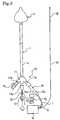
- FIG. 1is a cross-section view showing a critical part at the tip of a catheter for use in the treating of arrhythmia in accordance with an embodiment of the present invention.
- FIG. 2is a cross-section taken in the plane II-II shown in FIG. 1 .
- FIG. 3is a schematic view showing the configuration of the entire catheter shown in FIG. 1 .
- FIG. 5is a cross-section view showing a critical part at the tip of a catheter for use in the treating of arrhythmia in accordance with another embodiment of the present invention.
- FIG. 6is a cross-section view showing a critical part at the tip of a further catheter for use in the treating of arrhythmia in accordance with yet another embodiment of the present invention.
- FIG. 9is a cross-section view showing a critical part at the tip of a catheter for use in the treating of arrhythmia in accordance with yet another embodiment of the present invention.
- FIG. 11is a cross-section view showing a critical part at the tip of a catheter for use in the treating of arrhythmia in accordance with yet another embodiment of the present invention.
- FIG. 12is a schematic view related to the dimensions upon inflation of the balloon used in the embodiment of FIG. 1 .
- FIG. 13is a schematic view related to the dimensions upon inflation of the balloon used in the embodiment of FIG. 7 .
- FIG. 14is a cross-section view showing a guide wire used in the catheter for use in the treating of arrhythmia in accordance with the present invention and excluding the intermediate portion thereof.
- FIG. 15is a cross-section view showing a guide wire used in another embodiment of the catheter for use in the treating of arrhythmia in accordance with the present invention and excluding the intermediate portion thereof.
- FIG. 16is a cross-section view showing a stylette used in a catheter for use in the treating of arrhythmia in accordance with the present invention and excluding the intermediate portion thereof
- FIG. 17is an enlarged view of section A shown in FIG. 16 .
- FIG. 18is a cross-section view showing another embodiment of a stylette used in a catheter for use in the treating of arrhythmia in accordance with the present invention and excluding the intermediate portion thereof.
- FIG. 19is an enlarged view of section B shown in FIG. 18 .
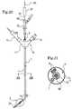
- FIG. 20is a schematic view showing the condition upon insertion of the stylette into a catheter for use in the treating of arrhythmia in accordance with a further embodiment of the present invention.
- FIG. 21is a cross-section taken in the plane XXI-XXI shown in FIG. 20 .
- FIG. 1 through FIG. 3show a series of catheters for use in the treating of arrhythmia in accordance with the present invention.
- a balloon 2capable of being inflated and deflated is mounted to the tip of a catheter shaft 1 .
- the catheter shaft 1comprises a double-cylinder structure with an inner shaft 3 and an outer shaft 4 , and the inner shaft 3 is inserted in such a way that longitudinal sliding thereof with respect to the inner shaft 3 and the outer shaft 4 is possible.
- the inner shaft 3 and the outer shaft 4are both made from a radiopaque resin material and with antithrombogenic properties, and metal pipes 3 a , 4 a with radiation shielding properties are connected to the tips of each shaft 3 , 4 .
- the balloon 2is fixed at the front end thereof to the metal pipe 3 a and at the rear end thereof to the metal pipe 4 a , straddling the opening between both metal pipes 3 a , 4 a.
- the metal pipes 3 a , 4 aare provided for identifying the positions of the tip of the inner shaft 3 and the tip of the outer shaft 4 when viewed using x-rays, and this allows the position of the balloon 2 to be determined.
- tip of the inner shaft 3and “tip of the outer shaft 4 ” will, unless otherwise specified, not refer directly to the tips of inner shaft 3 and outer shaft 4 , but will also include ancillary items such as metal pipes 3 a , 4 a attached thereto.
- the front end of the balloon 2extends forward from the fixed section attached to the tip of the inner shaft 3 , and having protruded from the tip thereof, inverts to extend rearward. Accordingly, this configuration ensures that the front edge of the balloon 2 is always disposed more forward than the tip of the inner shaft 3 when, at the very least, the balloon 2 is deflated.
- a high frequency current-carrying electrode 5comprising a coil body made by winding a wire in a spiral configuration is mounted around the tip of the inner shaft 3 that faces the inside of the balloon 2 .
- a high frequency current-carrying electrode 18is mounted outside of the balloon 2 as a counter electrode for the high frequency current-carrying electrode 5 (see FIG. 3 ).
- the high frequency current-carrying electrode 18is attached to the surface of the patient's body during ablation treatment.
- a temperature sensor 6is fixed in the high frequency current-carrying electrode 5 installed inside of the balloon 2 , and the temperature within the balloon 2 is monitored using this temperature sensor 6 .
- An electrode lead wire 7 and a temperature sensor lead wire 8are connected to the high frequency current-carrying electrode 5 and the temperature sensor 6 respectively, and after being secured of each to the metal pipe 4 a using a retainer 19 , are extended to a operation section 10 mounted on the rear end of the catheter shaft 1 along the clearance between the inner shaft 3 and the outer shaft 4 , and are connected to a high frequency generating device 16 provided in the operation section 10 (see FIG. 3 ).
- anti-elongation string 9is inserted in parallel into the catheter shaft 1 . The front end of the string 9 is secured to the tip of the outer shaft 4 through entrapment by the metal pipe 4 a , and the rear end thereof is secured to the operation section 10 .
- the anti-elongation string 9prevents elongation of the catheter shaft 1 softened through heating, and as a result, favorable operation of the catheter can be maintained.
- a four-way connector 11is secured to the rear end of the outer shaft 4 . Furthermore, the rear end of the inner shaft 3 extends outward to pass through a central branch pipe 11 a of the four-way connector 11 , and the extended end section is connected to a operation handle 12 .
- the tip of the balloon 2advances forward in an axial direction, allowing the external diameter thereof to be changed.
- a scale 20is provided on the surface of the rear end of the inner shaft 3 , and using the scale 20 , the degree of sliding (or length) of the inner shaft 3 is measured and the outer diameter of the balloon 2 can be determined.
- the scale 20may directly indicate the degree of sliding of the inner shaft 3 , or alternatively, and indicate the outer diameter of the balloon 2 calculated based on the degree of sliding of the inner shaft 3 .
- the side junction pipe 11 bis connected to a two-way connector 13
- the other side junction pipe 11 cis connected to a Y-shaped connector 14
- the junction pipe 14 ais connected to a two-way connector 15
- the electrode lead wire 7 and the temperature sensor lead wire 8pass through the other junction pipe 14 b
- the electrode lead wire 7 and temperature sensor lead wire 8 extending from the junction pipe 14 bare each connected to the high frequency generating device 16 .
- the electrode lead wire 7is connected to the high frequency generating device 16 , as is an electrode lead wire 17 extending from the high frequency current-carrying electrode 18 .
- the high frequency generating device 16provides high frequency power to the high frequency current-carrying electrodes 5 , 18 via the electrode lead wires 7 , 17 respectively; accordingly, high frequency waves are transmitted between the electrodes 5 , 18 and the temperature of the dilute contrast media solution contained within the balloon 2 rises as a result of high frequency induced heating and Joule heating, realizing circumferential ablation of the area of the patient's body in contact with the balloon 2 .
- FIG. 4shows a schematic diagram of the situation upon treating of arrhythmia using the above-described catheter.
- a guide wireis used as a secondary means when inserting a catheter into the patient.
- a guide wireis initially inserted in advance of catheter insertion, and following this, the catheter is inserted and guided by the guide wire.
- the ideal guide wire for use with the catheter in accordance with the present inventionis described hereinafter.
- a guide wire(not shown) is inserted from the patient's inner thigh via the inferior vena cava 41 to the right atrium 42 a of the heart 40 . It then passes from the right atrium 42 a to the left atrium 44 via the interatrial septum 43 . After setting of the guide wire has been completed, the deflated balloon 2 is inserted into the left atrium 44 of the heart 40 via the inferior vena cava 41 as the catheter's inner shaft 3 is guided by the guide wire.
- dilute contrast media solutionis introduced by either the two-way connector 13 or the two-way connector 15 to inflate the balloon 2 , causing the inflated balloon 2 to come into contact with and wedge one of the four openings ( 45 a , 45 b , 45 c , 45 d ) for the pulmonary vein 45 .
- the front edge of the soft balloon 2protrudes from the front edge of the inner shaft 3 in the catheter in accordance with the present invention, insertion thereof into the inferior vena cava 41 and the heart 40 with the front edge of the balloon 2 as its leading edge can proceed smoothly with no interference with blood vessel junctions and the inside the heart and no other infliction of injury.
- high frequency powerwith a frequency selected from the 1 to 2,450 MHz range is supplied to the high frequency current-carrying electrodes 5 , 18 by the high frequency generating device 16 ; accordingly, high frequency waves pass between the high frequency current-carrying electrodes 5 , 18 and the temperature of the dilute contrast media solution contained within the balloon 2 rises, realizing circumferential ablation of the ostia of pulmonary vein in contact with the balloon 2 . As a result of this ablation, the ostia of pulmonary vein alone is electrically isolated from the left atrium 44 .
- the above-described catheter for use in the treating of arrhythmiahas been described in terms of an embodiment of the present invention. Including this embodiment, the present invention is configured as described hereinafter.
- the balloon materialhas elastic recovery properties, and while the possession of antithrombogenic properties alone is acceptable, the utilization of polyurethane polymer materials is particularly preferable.
- the examples of polyurethane polymer materialsinclude thermoresin polyurethanes, polyether polyurethane ureas, fluoropolyether polyurethane ureas, polyether polyurethane urea resins, polyether polyurethane urea amides, and the like.
- the polyurethane polymer materialhas, in particular, an instantaneous recovery rate of 90% or greater at the modulus of 300% elongation, and that the strength thereof be between 12 and 24 MPa.
- the shape of the balloonis such that, as illustrated in the embodiment shown in FIG. 1 , when under the deflated condition at the very least, the front edge thereof protrudes beyond the front edge of the inner shaft.
- a balloon shape that allows close contact to be made with the ostia of pulmonary veinis preferable.
- the balloon shapeis conical with a smaller diametric portion at the front and gradually increasing in diameter towards the rear thereof.
- the use of a conical balloonensures that complete circumferential contact can be easily made with the affected area of the ostia of pulmonary vein.
- the large diameter Da and a small diameter Db as shown in FIG. 12be such that the ratio thereof Da/Db is in the range of 5 to 12.
- the diametrical ratioensures the highest level of contact with the affected area when the ratio Da/Db is less than 5 or greater than 12, closeness of the contact is impaired.
- the term “large diameter” as used hererefers to the diameter of the portion of the balloon with the largest size upon inflation.
- the term “small diameter”refers to the diameter obtained on plane S which is perpendicular to the axial direction as shown in FIG. 12 when the edge at the smaller end is incident upon the plane S.
- the length La in the axial directionis between 10 and 40 mm. When La is within this range, the balloon will exhibit favorable operability within the atria and ventricles.
- the inflated balloonmay also be given a long cylindrical shape. More preferable is the curved cylinder illustrated in FIG. 8 .
- balloon 2 ′ with a cylindrical shape as shown in FIG. 7 and FIG. 8is preferably used when the affected area is not the entrance for the pulmonary vein 45 , but rather when performing ablation over a wide area at the tricuspid valve 46 between the right atria 42 a and 42 b .
- the outer curved side of the curved cylindrical balloon 2 ′ as shown in FIG. 8contact can be made easily with the inner wall of the tricuspidal valve 46 ; accordingly, more favorable ablation is realized.
- contactcan be made easily with the isthmus between the superior and inferior vena cava and the right atrium, and similarly, more favorable ablation is realized.
- the thickness of the balloon membrane upon deflationbe within the 100 to 300 ⁇ m range for the cylindrical balloon 2 ′.
- the length Lb in the longitudinal directionbe within the 10 to 40 mm range, and that the diameter Dc be within the 5 to 20 mm range.
- the ratio (Lb/Dc) between the length Lb and the diameter Dcbe between 1.5 and 8.0.
- a tube 20comprising a resin having a higher level of flexibility than the inner shaft 3 may be attached to the tip of the inner shaft 3 as shown in FIG. 10 preventing damage to blood vessels etc. when inserting the catheter from the inferior vena cava to the heart.
- the shape of the balloon when such a tube is implementedmay be conical or cylindrical.
- the tube 20is linked to the metal pipe 3 a having radiation shielding properties and mounted on the tip of the inner shaft 3 .
- the front edge of the balloon 2is secured to this metal pipe 3 a .
- the length of the tube 20it is acceptable for the length of the tube 20 to be such that it extends at least 1 mm from the tip of the inner shaft 3 (or metal pipe 3 a ), an allowable length of 50 mm or less is favorable.
- the tip of the tube 20penetrates deep into the pulmonary vein, and the liquid introduced during ablation may enter the lungs.
- the tube 20is mounted onto the tip of the inner shaft 3 using the metal pipe 3 a as illustrated in the figure, the tube 20 may be formed together with the inner shaft 3 into a single component with a hardness gradient. In this way, the single component with a hardness gradient and comprising both tube and inner shaft together with a hardness gradient, eliminates the need for a connection between tips via the metal pipe, improving productivity.
- the material forming the catheter's inner shaft and outer shaft in the present inventionmay exhibit antithrombogenic properties within blood vessels, it is preferable that a resin with a low specific inductive capacity be used.
- the value of the specific inductive capacityit is acceptable that the value if 3 or less when measured at a frequency of 1 MHz.
- the specific inductive capacity referred to hereinis measured in accordance with JIS K 6911 specifications.
- Fluororesinpolytetrafluoroethylene, polytetrafluoroethylene hexafluoro-propylene copolymers, tetrafluoroethylene fluoro-alkyl ether copolymers
- polyethylenepolyimide resin, polyamide resin, thermoresin elastomers (polyamide, styrene, polyester, or olefin base), polypropylene, and methylpentene polymers, etc. are identified as low specific inductive capacity resin for use in the catheter shaft.
- the catheter shaftBy forming the catheter shaft using such a resin with the specific inductive capacity of 3 or less at a frequency of 1 MHz, it is possible to eliminate the need for the cooling water circulation tube required for cooling of the catheter shaft in the prior art. Accordingly, the catheter shaft can be reduced in diameter, improving the handling of the catheter.
- the tip of the inner shaft and the outer shaftare each attached by fitting to a metal pipe with radiation shielding properties, and that the front edge and rear edge of the balloon are secured on this metal pipe.
- a metal pipe with radiation shielding propertieson each of the tips of the inner shaft and the outer shaft in this way, the position of the metal pipe can be clearly distinguished in x-ray images, allowing easy confirmation of the position of the balloon within the heart.
- the metal used for the radiation shielding pipeis not particularly limited as long as it exhibits a low transparency to ionizing radiation; however, the metals preferably used include gold, platinum, stainless steel, and Ti—Ni alloys.
- the catheter of the present inventionprovides a pair of high frequency current-carrying electrodes to facilitate the raising of temperature through high frequency induction heating and Joule heating, and at least, one of the electrodes thereof is provided on the inner side of the balloon. It is acceptable for the other electrode to be attached to the surface of the patient's body or so as to form a pair within the balloon.
- the shape of the electrode from the pair of high frequency current-carrying electrodes that is provided inside the balloonis preferable for example that this be formed around the outside of the inner shaft using a coil body upon which metal wire is wrapped in a spiral configuration.
- a coil body 5 to which the flat metal wire 5 a of the section shown in the embodiment of FIG. 5 has been wrapped in a spiral configurationit is acceptable to use a coil body 5 to which the flat metal wire 5 a of the section shown in the embodiment of FIG. 5 has been wrapped in a spiral configuration.
- the thickness of the flat metal wire 5 abe between 0.05 and 0.2 mm.
- the high frequency current-carrying electrode 5By forming the high frequency current-carrying electrode 5 from coil body of a flat metal wire 5 a , it is possible to realize not only a small coil-body diameter, but also a balloon having a small diameter when it is deflated; accordingly, the ease of insertion of the catheter into the patient and operation therein is improved. If the thickness of the metal wire were less than 0.05 mm, it would be difficult to maintain the strength required as an electrode; furthermore, if the thickness thereof were in excess of 0.2 mm, the above-described reduction of diameter would be difficult to achieve.
- the high frequency current-carrying electrode disposed inside the balloonmay be formed as a film applied onto the inner circumference of the balloon as shown in the embodiment of FIG. 6 .
- the high frequency current-carrying electrode 5as a film applied onto the inner circumference of the balloon in this way, heating can be applied uniformly and evenly over the entire contact area, avoiding partially insufficient or excess ablation, regardless of the way in which the balloon is in contact with the affected area of the ostia of pulmonary vein.
- the outer diameter of the deflated ballooncan be made significantly smaller.
- the thickness of the planer electrode described abovebe between 5 and 20 ⁇ m, and the examples of the electrically conductive material used for the planer electrode include gold, silver, platinum, copper, and aluminum etc. can be identified.
- Method for forming the planer electrodemay be chosen from vapor deposition, plating, painting, and other similar methods of the electrically conductive material.
- the above-described planer electrodebe formed so as to coat at least half of the front edge of the balloon, and there is no need for this electrode to coat the complete inner surface thereof.
- the other electrode from the pair of high frequency current-carrying electrodesis provided through attachment to the surface of the patient's body.
- a sheet-type planer electrodebe used.
- planer electrodes of oneis acceptable for this purpose, it is also acceptable for a multiplicity thereof, and preferably two or three, to coat an equal surface area by each planer electrode.
- the surface area per planer electrodebe at least 80 cm 2 .
- the maximum surface area of the planer electrodebe 600 cm 2 .
- one electrode 5 of a pair of high frequency current-carrying electrodescomprises a coil body formed from conductive wires as described above; furthermore, the other electrode 18 comprises a flat plate or mesh of electrically conductive material.
- the lead wires 7 , 17 of the electrodes 7 , 17are combined within a coaxial cable construction 22 and extend to the rear end of the catheter shaft 1 via the clearance between the inner shaft 3 and the outer shaft 4 .
- the pair of high frequency current-carrying electrodes 5 , 18can be provided within the balloon 2 ; accordingly, it is possible to restrict the high frequency transmission between the high frequency current-carrying electrodes 5 , 18 to the inside of the balloon 2 . Furthermore, as it is not necessary for the electrode 18 to be applied to the surface of the patient's body and because the high frequency transmission between the high frequency current-carrying electrodes 5 , 18 is restricted to the inside of the balloon 2 , leakage of high frequency waves to the exterior is reduced.
- the material forming the electrode lead wires connected to the high frequency current-carrying electrodesare not particularly limited as long as they are characterized by low heat generation and low energy loss upon high frequency current-carrying.
- the examples of the materials used for the lead wireinclude gold, silver, copper, aluminum, and platinum etc.
- the electrode lead wiresare coated with a shielding resin having low dielectric constant.
- the resin used for shieldinghas a dielectric constant of 3 or less when measured at a frequency of 1 MHz.
- a shielding resin having a high dielectric constantis used, it may become difficult to restrain the heating of the catheter shaft that originates in the high frequency current-carrying electrodes. In such a case, a cooling-water circulation tube would become necessary, leading to the problem of an increased catheter shaft diameter.
- FluororesinsPTFE, FEP, PFA
- polyethylene, polystyrene, and polyurethane, etc.can be identified as examples of resins for use as the shielding material.
- ablation treatmentis realized by providing a frequency selected from the range of 1 to 2,450 MHz to a pair of high frequency current-carrying electrodes.
- relatively low frequencies from the above-described frequency rangesuch as 13.56 MHz, are characterized in that exothermic occurs in a fat layer, which shows a high resistance.
- these relatively low frequencies from the frequency bandhave low levels of directionality with respect to fat layers and considerable time is required for heating, leading to the problem of poor heating efficiency. Accordingly, it is more preferable for efficient heating over a short period of time to be realized using high frequencies in the 100 to 2,450 MHz range. In addition, this also allows the generation of high temperatures to be limited to the areas where it is required.
- the temperature sensor used in the present inventionbe capable of measuring the temperature within the balloon; however, it is preferable that a thermocouple be used for this purpose.
- the temperature data monitored by the temperature sensoris provided to the high frequency generating device in the form of feedback.
- the high frequency generating deviceoutputs power to the high frequency current-carrying electrodes based on the temperature data received as feedback so as to maintain the temperature of the interior of the balloon within the required range.
- the temperature sensorbe disposed close to the axis of the balloon. Since the actions of inflation and deflation take place about the central axis of the balloon, there would be increased danger of contact between the sensor and the balloon membrane and the balloon suffering damage during these actions if the temperature sensor were to be disposed away from this axis in the radial direction.
- the temperature sensormay, as illustrated in the embodiment of FIG. 1 , be provided in a fixed condition in the high frequency current-carrying electrode.
- the temperature of the solution within the balloon as described aboveis not necessarily uniform over the entire balloon: accordingly, if the temperature sensor is provided in a fixed condition within the high frequency current-carrying electrode and is capable of directly detecting the temperature thereof, the relationship between the electrode temperature and the temperature of the balloon tip region making contact with the affected area can be measured in advance in order to facilitate accurate temperature monitoring.
- the material of the lead wires connected to the temperature sensoris a conductor allowing transmission of the electrical signal corresponding to the temperature monitored by the temperature sensor. Platinum, tungsten, copper, alloys of these metals, and chromel, etc. can be identified as examples thereof.
- the lead wires of the temperature sensorbe coated with a shielding material. In the same way as for the electrode lead wires, it is preferable that this shielding material be a resin with a specific inductive capacity of 3 or less at a frequency of 1 MHz.
- both the above-described high frequency current-carrying electrodes and temperature sensorprefferably be secured by a securing tool via the corresponding lead wires.
- a securing toolsuch as clamp or band type members formed of resin, aramid fiber, or the like may be preferably used. Securing of the high frequency current-carrying electrodes and the temperature sensor through the action of securing tools ensures that, even after repeated inflation and deflation of the balloon, the high frequency current-carrying electrodes and the temperature sensor will not be displaced from their original positions and that suitable heating and temperature monitoring can be realized.
- the catheter shaftsoftens and elongates during usage as a result of heating occurring due to high frequency current-carrying; accordingly, extreme difficulty is experienced during operations such as balloon inflation, balloon deflation, and balloon extraction.
- itis effective to dispose inextensible string in parallel to the catheter shaft.
- the mounting of the inextensible stringit is preferable for one end thereof to be secured to the tip of the outer shaft and for the other end thereof to be secured to the operation section provided at the rear end of the outer shaft.
- Polyimide fiber, polyester fiber, polyethylene fiber, carbon fiber, and aramid fibercan be identified as examples of the preferable material for use as the anti-elongation string.
- the diameter of the anti-elongation stringit is acceptable for the diameter of the anti-elongation string to be in the 0.05 to 1 mm range. If the string were to be less than 0.05 mm in thickness, it would be difficult to assure the strength required for reliable usage of the catheter as described above. Furthermore, it the string were to be thicker than 1 mm, disposition thereof between the outer shaft and inner shaft would be problematic.
- the catheter of FIG.11provides potential detection electrodes 23 , 24 on the tip of the inner shaft 3 and the tip of the outer shaft 4 at the opposite sides of the balloon 2 so as to enable measurement of the potential of the ablation area with which the balloon 2 makes contact.
- the potential detection electrode 23 at the tip of the inner shaft 3links the resin pipe 25 to the radiation shielding metal pipe 3 a linked to the inner shaft 3 and is secured on the resin pipe 25 .
- Also attached to the tip of the resin pipe 25is the soft tube 20 illustrated in FIG. 10 .
- the potential detecting electrode 24 disposed at the tip of the outer shaft 4is directly secured to the outer shaft 4 .
- Each of the lead wires 26 , 27 connected to the potential detecting electrodes 23 , 24 , respectively,is coated with an electrically-insulating coating material and is connected to a potentiometer (not shown) disposed at the rear end of the catheter shaft 1 via the clearance between the inner shaft 3 and the outer shaft 4 .
- a potentiometernot shown
- the route of passage of the lead wires 26 , 27 to the rear end of the catheter shaft 1may be such that the lead wire 26 to passes through the material thickness of the inner shaft 3 , and the lead wire 27 passes through the material thickness of the outer shaft 4 .
- the potential detecting electrodesare intended to directly measure the potential of the ablation area, disposition of them at both sides of the balloon 2 as shown in the embodiment of FIG. 11 is not absolutely necessary and disposition of both thereof at either end is acceptable. It is also acceptable for three or more potential detection electrodes to be employed where so required.
- a guide wire with a suitable balance of rigidity and flexibilityis used as an auxiliary tool of a guide.
- the guide wireensures that the catheter can be inserted efficiently into the patient with no damage done to blood vessels or tissue, and by contributing to catheter rigidity, it plays an important role in maintaining the catheter in the required position.
- the guide wire 50 illustrated in FIG. 14is formed by extending a single metal wire 51 with a suitable balance of rigidity and flexibility, over the entire length.
- the majority of the length of the metal wire 15corresponds to the operation section 52 , and a flexible section 53 is formed at the tip thereof.
- the flexible section 53comprises a taper section 54 wherein the diameter of the metal wire 51 from the operation section 52 becomes gradually smaller and a small diameter section 55 with the same diameter as the small end of the taper section 54 and attached thereto.
- a contrast marker 56is attached to the tip of the small diameter section 55 .
- the contrast marker 56is formed as a metal wire coil with radiation shielding properties wound in a spiral configuration or as a braided section and is welded to the tip of the small diameter section.
- the outer diameter thereofis either equal to or slightly smaller than the diameter of the operation section 52 .
- the flexible section 53including the contrast marker 56 , is completely coated by a resin 57 with low specific inductive capacity such that the external diameter thereof is approximately equal to that of the operation section 52 .
- a resin with a specific inductive capacity value of 3 or less at a frequency of 1 MHzis used.
- the operation section 52is coated on the surface with a thin film of resin 58 such as fluororesin or silicone with low resistance to sliding.
- the above-described resin 57 of low specific inductive capacitymay be coated on the entire surface of the guide wire 50 as well as the flexible section 53 .
- the tip of the metal guide wireis also heated when these waves are transmitted thereby, and ablation of blood vessels and tissue outside the affected area may be performed by this tip.
- the flexible section 53is coated by resin 57 , if the guide wire 50 as shown in FIG. 14 or FIG. 15 is used, the problem of ablation of sections other than that affected area can be eliminated.
- the guide wire 50by providing the guide wire 50 with a suitable degree of rigidity, it is possible to augment the rigidity of the catheter shaft softened through heating, improving the performance thereof.
- the metal used in the above-described guide wirebe stainless steel wire, piano wire, or a shape memory alloy etc. Of these, stainless steel wires are more preferable, specifically SUS301H, SUS301SEH, or similar varieties with high rigidity.
- the diameter of the operation sectionbe between 0.5 and 1.5 mm from the point of view of attaining suitable stiffness for convenient operation.
- the flexible sectionin order to improve flexibility and ensure that no damage is done to blood vessels and other tissues even when contact is made, it is acceptable for the diameter of the small diameter section to be between 0.05 and 0.30 mm, and more preferably in the range 0.05 to 0.15 mm.
- a contrast markerfacilitates confirmation of the position of the guide wire by fluoroscopy.
- the contrast markerallows confirmation of the arrival of the tip of the guide wire in the target area.
- the examples of the metal suitable for the contrast markerinclude gold, platinum, silver, bismuth, tungsten, and alloys wherein these metals comprise the main component can be identified as suitable. It is acceptable for the coil, mesh, or tube comprising this metal to be welded to the tip of the small diameter section or to be press-fitted therein for the purpose of mounting.
- the range of the flexible sectioncoat the low specific inductive capacity resin, including the contrast marker section. Coverage by this low specific inductive capacity resin prevents the tip of the guide wire from being heated. It is preferable that the length of the flexible section coated with a resin be between 50 and 200 mm. Furthermore, it is preferable that the thickness of the coating resin be between 0.1 and 0.5 mm.
- the method for coating a resinis not particularly limited as long as it fits the purpose of the present invention. The examples of the method include, direct coating and coating through the formation of a tube are acceptable.
- hydrophilic coatingis also formed on the surface of the above-described resin, handling and insertion of the guide wire can be further improved.
- This hydrophilic coatingcan be easily formed through hydrophilic processing of the surface of the resin. In terms of hydrophilic processing, it is preferable that contact between a compound containing at least two isocyanate radicals and the surface of the resin be carried out, and furthermore, that reaction with an hydrophilic polymer be realized.
- diphenylmethane diisocyanatediisocyanatohexane, xylene diisocyanate, triphenylmethane diisocyanate, toluylene diisocynate, etc. be used.
- methyl ethyl ketone, trichloroethylene, chloroform, or dichloromethane etc.be used as the solvent for dissolution of the compound containing at least two isocyanate radicals. It is acceptable that the above-described compound containing at least two isocyanate radicals be dissolved in this solvent to form a solution, and for this solution to be brought into contact with the resin surface. Following this, a reaction with the hydrophilic polymer is realized, and in terms of the hydrophilic polymer, polyvinyl alcohol, polyethylene oxide, polyethylene glycol, methyl vinyl ether maelic anhydride copolymer, and polyvinyl-polypyrrolidone etc. can be specifically identified.
- an antithrombogenic coatingcan be formed on the surface of coating resin.
- Such an antithrombogenic coatingcan be formed by, for example, subjecting the surface of the resin to antithrombogenic processing.
- a preferable method of antithrombogenic processingcomprises steps of graft activation of hydrophobic polymer by light exposure, etc.; coating the surface of the resin with the copolymer made by graft or block polymerization between a hydrophilic monomer and a graft activated hydrophobic polymer described above; and that heparin or its salt be ion bonded after drying.
- PVCmethyl methacrylate, styrene, acrylonitrile, vinyl acetate, and glycidl methacrylate, etc.
- hydrophobic polymermethyl methacrylate, styrene, acrylonitrile, vinyl acetate, and glycidl methacrylate, etc.
- hydrophilic monomervinyl compounds, divinyl compounds, cyclic ether compounds, and cyclic imine compounds etc. are used.
- the safety of the guide wirecan be improved.
- the surface of the metal wire in the operation sectionbe coated with a thin film of fluororesin or silicon, which affect the human body little.
- the above-described guide wireis effective as a support member for the catheter, in cases where the target affected area is in the lower left ostium of pulmonary vein or the lower right ostium of pulmonary vein, it does not function to guide the balloon to said area and to promote contact therebetween.
- the stylet shown in FIG. 16 and FIG. 17constitutes a support member for a catheter effective in such a situation.
- a core wire 61comprising a metal with shape memory and radiation shielding properties extends over the full length of the stylet 60 shown in FIG. 16 and FIG. 17 .
- the tip of this core wire 61is fabricated so as to have a smaller diameter than the rear section, and a coil section 63 fabricated from metal wire 62 with radiation shielding properties coats the outside thereof and is secured thereto by welding.
- the tip coated by the coil section 63is formed as a preliminary deformed portion 64 .
- the entire stylet 60is coated with a coating material 65 , and a stopper 66 and turning handle 67 are provided in the rear section.
- the above-described preliminary deformed portion 64has a curved condition when unloaded, it can easily extend into a straight-line configuration under the influence of external force, and furthermore, it is capable of returning elastically to its original curved shape when the external force is removed.
- the core wire 61 of the preliminary deformed portion 64has a smaller diameter than the rear end and deflects easily; furthermore, by providing a coil 63 on the outer surface thereof, the curved shape can be easily retained.
- the outer diameter of the coil 63is larger than the outer diameter of the rear end of the core wire 61 ; however, in the stylet 60 in the embodiment of FIG. 18 and FIG. 19 , the outer diameter of the coil 63 is identical to the outer diameter of the rear end of the core wire 61 , and all other configuration aspects are identical.
- the above-described stylet 60is used as shown in FIG. 20 and FIG. 21 as a support member for the catheter.
- the catheterprovides the basic configuration of a catheter for use in the treating arrhythmia according to the present invention, and in addition, provides a flexible section la in the vicinity of the tip of the catheter shaft 1 whereto a balloon 2 is attached.
- the flexible section lais processed so as to be less rigid than the body of the catheter shaft 1 , and it can easily be deflected.
- thiscan be achieved by, for example, reduction of material thickness through the dissolution of a portion of the material of the outer shaft 4 by using an organic solvent, combination with a low-rigidity tube disposed therebetween, or by increasing the ratio of plasticizer.
- the axial directions of the catheter shaft 1 and the balloon 2are identical when the stylet 60 is not inserted.
- the stylet 60is inserted into the catheter's inner shaft 3 from the rear end, and the preliminary deformed portion 64 is inserted from the flexible section la to the tip of the balloon 2 , as shown in FIG. 20 , the flexible section la is deflected by the elastic return force of the preliminary deformed portion 64 , and the axial direction of the balloon 2 is inclined at an angle ⁇ with respect to the axial direction of the catheter shaft 1 .
- the ability to incline the balloon 2ensures that, even when the target affected area is in the lower left ostium of pulmonary vein or the lower right ostium of pulmonary vein etc., the balloon 2 can be accurately guided to the affected area and a close contact can be realized therebetween. Furthermore, by providing the stylet 60 with a suitable degree of rigidity, it is possible to augment the rigidity of the catheter shaft, improving the performance thereof.
- a clearanceis formed between the stylet 60 and the inner shaft 3 , and physiological saline, grape sugar solution, blood, and other liquids with a viscosity of 5 mPa ⁇ s or less flowing through this clearance can be drawn in or charged via the tube 20 of the balloon 2 tip at a speed of approximately 5 to 15 ml/minute.
- the core wirecomprises any metal with high rigidity, shape memory, and radiation shielding properties; however, stainless steels are preferably used.
- stainless steelsare preferably used.
- SUS302, SUS304, and SUS316are preferable, and in terms of tensile strength, it is acceptable for this material to be of class A through C as set forth in JIS G 4314, with class B being preferable.
- the outer diameter of the core wire 61it is preferable that this be between 0.5 and 1.5 mm at the straight-shaped end section; furthermore, in the preliminary deformed portion 64 at the tip, a smaller diameter than that of the end section is preferable as a means of achieving greater flexibility.
- the metal wire 62 forming the coil 63can be any metal with radiation shielding properties; however, it is preferable that either stainless steels or platinum are preferably used.
- the diameter of the metal wire 62 of the coil 63is approximately 0.1 mm, and this coil is wound about the small-diameter section of the core wire 61 in order to achieve close contact therewith. It is preferable that the outer diameter of the coil 63 be between 0.5 and 1.5 mm, and as shown in the example of FIG. 19 in particular, it is preferable that this diameter be the same as the outer diameter of the end section.
- Both ends of the metal wire 62 of the coil 63are welded to the core wire 61 . Furthermore, the tip of the coil 63 is processed with a spherical shape so as not to damage the walls of blood vessels etc. when contact is made therewith.
- the length of the coil 63is determined based on the length of the small-diameter section of the core wire 61 , it is preferable that this be between 50 and 150 mm.
- the coil 63is providing so that the curved shape of the preliminary deformed portion 64 can be maintained and elastic return can be easily achieved; however, it is acceptable for this member to be formed using braided wire.
- coating material 65be provided on some or all of the stylet 60 .
- This coating material 65enables easy sliding of the stylet 60 within the catheter's inner shaft 3 , reduces the resistance to insertion therein, and improves operability when selecting the target affected area; furthermore, it also has the effect of reducing conductance to the stylet 60 due to the high frequency waves used during ablation etc.
- the coating material 65be a resin with a low specific inductive capacity, and specifically, has a specific inductive capacity of 3 or less at a frequency of 1 MHz.
- fluororesini.e., (polytetrafluoroethylene, polytetrafluoroethylene hexafluoro-propylene copolymers), polyethylene, polyimide resin, polyamide resin, thermoresin elastomerspolypropylene, and methylpentene polymers, etc. are identified as low specific inductive capacity resin for use as the coating material.
- hydrophilic resins, etc.including —OH, —CONH 2 , —COOH, and NH 2 hydrophilic radicals to be secured as a means of imparting low friction properties to the coating material.
- a stopper 66is provided on the rear end of the stylet 60 for fixing position upon insertion into the body.
- the stopper 66provided an acurate position of inserted of the preliminary deformed portion 64 with respect to the catheter within for the flexible section 1 a and the balloon 2 .
- This stopper 66is formed so as to be larger than the insertion port of the operation section 10 ; accordingly, stopping at the specified position becomes possible.
- a rotating handle 67is provided further back than the stopper 66 at the rear end section of the stylet 60 .
Landscapes
- Health & Medical Sciences (AREA)
- Surgery (AREA)
- Life Sciences & Earth Sciences (AREA)
- Engineering & Computer Science (AREA)
- Heart & Thoracic Surgery (AREA)
- Medical Informatics (AREA)
- Otolaryngology (AREA)
- Plasma & Fusion (AREA)
- Physics & Mathematics (AREA)
- Biomedical Technology (AREA)
- Veterinary Medicine (AREA)
- Nuclear Medicine, Radiotherapy & Molecular Imaging (AREA)
- Molecular Biology (AREA)
- Animal Behavior & Ethology (AREA)
- General Health & Medical Sciences (AREA)
- Public Health (AREA)
- Cardiology (AREA)
- Surgical Instruments (AREA)
- Media Introduction/Drainage Providing Device (AREA)
- Electrotherapy Devices (AREA)
Abstract
Description
Instantaneous recovery rate for 300% elongation (%)=(original length/length after instantaneous recovery)×100
Claims (3)
Applications Claiming Priority (5)
| Application Number | Priority Date | Filing Date | Title |
|---|---|---|---|
| JP2002239407AJP2004073570A (en) | 2002-08-20 | 2002-08-20 | Balloon catheter for electrical separation of pulmonary vein |
| JP2002-239407 | 2002-08-20 | ||
| JP2002-379830 | 2002-12-27 | ||
| JP2002379830 | 2002-12-27 | ||
| PCT/JP2003/010503WO2004017850A1 (en) | 2002-08-20 | 2003-08-20 | Catheter for treating irregular heart pulse |
Publications (2)
| Publication Number | Publication Date |
|---|---|
| US20050203597A1 US20050203597A1 (en) | 2005-09-15 |
| US7744594B2true US7744594B2 (en) | 2010-06-29 |
Family
ID=31949542
Family Applications (1)
| Application Number | Title | Priority Date | Filing Date |
|---|---|---|---|
| US10/522,788Active2027-11-16US7744594B2 (en) | 2002-08-20 | 2003-08-20 | Catheter for treating of arrhythmia |
Country Status (10)
| Country | Link |
|---|---|
| US (1) | US7744594B2 (en) |
| EP (1) | EP1547537B1 (en) |
| KR (1) | KR101032220B1 (en) |
| CN (1) | CN100594847C (en) |
| AU (1) | AU2003257613A1 (en) |
| CA (1) | CA2494123C (en) |
| DK (1) | DK1547537T3 (en) |
| ES (1) | ES2539106T3 (en) |
| TW (1) | TWI235073B (en) |
| WO (1) | WO2004017850A1 (en) |
Cited By (96)
| Publication number | Priority date | Publication date | Assignee | Title |
|---|---|---|---|---|
| US20090018501A1 (en)* | 2007-07-13 | 2009-01-15 | Yribarren Travis R | Drug Coated Balloon Catheter |
| US20090254063A1 (en)* | 2007-07-13 | 2009-10-08 | Randolf Von Oepen | Drug Coated Balloon Catheter |
| US8636721B2 (en) | 2003-11-20 | 2014-01-28 | Henry M. Jackson Foundation For The Advancement Of Military Medicine, Inc. | Portable hand pump for evacuation of fluids |
| US20140058376A1 (en)* | 2012-08-24 | 2014-02-27 | Boston Scientific Scimed, Inc. | Renal nerve modulation devices with weeping rf ablation balloons |
| US8814839B2 (en) | 2004-10-12 | 2014-08-26 | C. R. Bard, Inc. | Corporeal drainage system |
| US20140249570A1 (en)* | 2009-04-06 | 2014-09-04 | Stryker Corporation | Delivery wire for occlusive device delivery system |
| US8880185B2 (en) | 2010-06-11 | 2014-11-04 | Boston Scientific Scimed, Inc. | Renal denervation and stimulation employing wireless vascular energy transfer arrangement |
| US8939970B2 (en) | 2004-09-10 | 2015-01-27 | Vessix Vascular, Inc. | Tuned RF energy and electrical tissue characterization for selective treatment of target tissues |
| US8951251B2 (en) | 2011-11-08 | 2015-02-10 | Boston Scientific Scimed, Inc. | Ostial renal nerve ablation |
| US8974451B2 (en) | 2010-10-25 | 2015-03-10 | Boston Scientific Scimed, Inc. | Renal nerve ablation using conductive fluid jet and RF energy |
| US9023034B2 (en) | 2010-11-22 | 2015-05-05 | Boston Scientific Scimed, Inc. | Renal ablation electrode with force-activatable conduction apparatus |
| US9028485B2 (en) | 2010-11-15 | 2015-05-12 | Boston Scientific Scimed, Inc. | Self-expanding cooling electrode for renal nerve ablation |
| US9028472B2 (en) | 2011-12-23 | 2015-05-12 | Vessix Vascular, Inc. | Methods and apparatuses for remodeling tissue of or adjacent to a body passage |
| WO2015079322A2 (en) | 2013-11-26 | 2015-06-04 | Newuro, B.V. | Bladder tissue modification for overactive bladder disorders |
| US9050106B2 (en) | 2011-12-29 | 2015-06-09 | Boston Scientific Scimed, Inc. | Off-wall electrode device and methods for nerve modulation |
| US9060761B2 (en) | 2010-11-18 | 2015-06-23 | Boston Scientific Scime, Inc. | Catheter-focused magnetic field induced renal nerve ablation |
| US9079000B2 (en) | 2011-10-18 | 2015-07-14 | Boston Scientific Scimed, Inc. | Integrated crossing balloon catheter |
| US9084609B2 (en) | 2010-07-30 | 2015-07-21 | Boston Scientific Scime, Inc. | Spiral balloon catheter for renal nerve ablation |
| US9089350B2 (en) | 2010-11-16 | 2015-07-28 | Boston Scientific Scimed, Inc. | Renal denervation catheter with RF electrode and integral contrast dye injection arrangement |
| US9119600B2 (en) | 2011-11-15 | 2015-09-01 | Boston Scientific Scimed, Inc. | Device and methods for renal nerve modulation monitoring |
| US9119632B2 (en) | 2011-11-21 | 2015-09-01 | Boston Scientific Scimed, Inc. | Deflectable renal nerve ablation catheter |
| US9125667B2 (en) | 2004-09-10 | 2015-09-08 | Vessix Vascular, Inc. | System for inducing desirable temperature effects on body tissue |
| US9125666B2 (en) | 2003-09-12 | 2015-09-08 | Vessix Vascular, Inc. | Selectable eccentric remodeling and/or ablation of atherosclerotic material |
| US9155589B2 (en) | 2010-07-30 | 2015-10-13 | Boston Scientific Scimed, Inc. | Sequential activation RF electrode set for renal nerve ablation |
| US9162046B2 (en) | 2011-10-18 | 2015-10-20 | Boston Scientific Scimed, Inc. | Deflectable medical devices |
| US9173696B2 (en) | 2012-09-17 | 2015-11-03 | Boston Scientific Scimed, Inc. | Self-positioning electrode system and method for renal nerve modulation |
| US9186209B2 (en) | 2011-07-22 | 2015-11-17 | Boston Scientific Scimed, Inc. | Nerve modulation system having helical guide |
| US9186210B2 (en) | 2011-10-10 | 2015-11-17 | Boston Scientific Scimed, Inc. | Medical devices including ablation electrodes |
| US9192790B2 (en) | 2010-04-14 | 2015-11-24 | Boston Scientific Scimed, Inc. | Focused ultrasonic renal denervation |
| US9192435B2 (en) | 2010-11-22 | 2015-11-24 | Boston Scientific Scimed, Inc. | Renal denervation catheter with cooled RF electrode |
| US9220561B2 (en) | 2011-01-19 | 2015-12-29 | Boston Scientific Scimed, Inc. | Guide-compatible large-electrode catheter for renal nerve ablation with reduced arterial injury |
| US9220558B2 (en) | 2010-10-27 | 2015-12-29 | Boston Scientific Scimed, Inc. | RF renal denervation catheter with multiple independent electrodes |
| US9265969B2 (en) | 2011-12-21 | 2016-02-23 | Cardiac Pacemakers, Inc. | Methods for modulating cell function |
| US9277955B2 (en) | 2010-04-09 | 2016-03-08 | Vessix Vascular, Inc. | Power generating and control apparatus for the treatment of tissue |
| US9297845B2 (en) | 2013-03-15 | 2016-03-29 | Boston Scientific Scimed, Inc. | Medical devices and methods for treatment of hypertension that utilize impedance compensation |
| US9326751B2 (en) | 2010-11-17 | 2016-05-03 | Boston Scientific Scimed, Inc. | Catheter guidance of external energy for renal denervation |
| US9327100B2 (en) | 2008-11-14 | 2016-05-03 | Vessix Vascular, Inc. | Selective drug delivery in a lumen |
| US9358365B2 (en) | 2010-07-30 | 2016-06-07 | Boston Scientific Scimed, Inc. | Precision electrode movement control for renal nerve ablation |
| US9364284B2 (en) | 2011-10-12 | 2016-06-14 | Boston Scientific Scimed, Inc. | Method of making an off-wall spacer cage |
| US9408661B2 (en) | 2010-07-30 | 2016-08-09 | Patrick A. Haverkost | RF electrodes on multiple flexible wires for renal nerve ablation |
| US9420955B2 (en) | 2011-10-11 | 2016-08-23 | Boston Scientific Scimed, Inc. | Intravascular temperature monitoring system and method |
| US9433760B2 (en) | 2011-12-28 | 2016-09-06 | Boston Scientific Scimed, Inc. | Device and methods for nerve modulation using a novel ablation catheter with polymeric ablative elements |
| US9463062B2 (en) | 2010-07-30 | 2016-10-11 | Boston Scientific Scimed, Inc. | Cooled conductive balloon RF catheter for renal nerve ablation |
| US9486355B2 (en) | 2005-05-03 | 2016-11-08 | Vessix Vascular, Inc. | Selective accumulation of energy with or without knowledge of tissue topography |
| US20160354555A1 (en)* | 2013-10-24 | 2016-12-08 | Amgen Inc. | Drug Delivery System With Temperature-Sensitive Control |
| US9579030B2 (en) | 2011-07-20 | 2017-02-28 | Boston Scientific Scimed, Inc. | Percutaneous devices and methods to visualize, target and ablate nerves |
| US9649156B2 (en) | 2010-12-15 | 2017-05-16 | Boston Scientific Scimed, Inc. | Bipolar off-wall electrode device for renal nerve ablation |
| US9668811B2 (en) | 2010-11-16 | 2017-06-06 | Boston Scientific Scimed, Inc. | Minimally invasive access for renal nerve ablation |
| US9687166B2 (en) | 2013-10-14 | 2017-06-27 | Boston Scientific Scimed, Inc. | High resolution cardiac mapping electrode array catheter |
| US9693821B2 (en) | 2013-03-11 | 2017-07-04 | Boston Scientific Scimed, Inc. | Medical devices for modulating nerves |
| US9707036B2 (en) | 2013-06-25 | 2017-07-18 | Boston Scientific Scimed, Inc. | Devices and methods for nerve modulation using localized indifferent electrodes |
| US9713730B2 (en) | 2004-09-10 | 2017-07-25 | Boston Scientific Scimed, Inc. | Apparatus and method for treatment of in-stent restenosis |
| US9757193B2 (en) | 2002-04-08 | 2017-09-12 | Medtronic Ardian Luxembourg S.A.R.L. | Balloon catheter apparatus for renal neuromodulation |
| US9770606B2 (en) | 2013-10-15 | 2017-09-26 | Boston Scientific Scimed, Inc. | Ultrasound ablation catheter with cooling infusion and centering basket |
| US9808311B2 (en) | 2013-03-13 | 2017-11-07 | Boston Scientific Scimed, Inc. | Deflectable medical devices |
| US9808300B2 (en) | 2006-05-02 | 2017-11-07 | Boston Scientific Scimed, Inc. | Control of arterial smooth muscle tone |
| US9827039B2 (en) | 2013-03-15 | 2017-11-28 | Boston Scientific Scimed, Inc. | Methods and apparatuses for remodeling tissue of or adjacent to a body passage |
| US9827040B2 (en) | 2002-04-08 | 2017-11-28 | Medtronic Adrian Luxembourg S.a.r.l. | Methods and apparatus for intravascularly-induced neuromodulation |
| US9833283B2 (en) | 2013-07-01 | 2017-12-05 | Boston Scientific Scimed, Inc. | Medical devices for renal nerve ablation |
| US9855089B2 (en) | 2014-03-21 | 2018-01-02 | Medtronic Cryocath Lp | Shape changing ablation balloon |
| US9895194B2 (en) | 2013-09-04 | 2018-02-20 | Boston Scientific Scimed, Inc. | Radio frequency (RF) balloon catheter having flushing and cooling capability |
| US9907609B2 (en) | 2014-02-04 | 2018-03-06 | Boston Scientific Scimed, Inc. | Alternative placement of thermal sensors on bipolar electrode |
| US9919144B2 (en) | 2011-04-08 | 2018-03-20 | Medtronic Adrian Luxembourg S.a.r.l. | Iontophoresis drug delivery system and method for denervation of the renal sympathetic nerve and iontophoretic drug delivery |
| US9925359B2 (en) | 2014-03-21 | 2018-03-27 | Medtronic Cryocath Lp | Balloon design to reduce distal length |
| US9925001B2 (en) | 2013-07-19 | 2018-03-27 | Boston Scientific Scimed, Inc. | Spiral bipolar electrode renal denervation balloon |
| US9943365B2 (en) | 2013-06-21 | 2018-04-17 | Boston Scientific Scimed, Inc. | Renal denervation balloon catheter with ride along electrode support |
| US9956033B2 (en) | 2013-03-11 | 2018-05-01 | Boston Scientific Scimed, Inc. | Medical devices for modulating nerves |
| US9962223B2 (en) | 2013-10-15 | 2018-05-08 | Boston Scientific Scimed, Inc. | Medical device balloon |
| US9974607B2 (en) | 2006-10-18 | 2018-05-22 | Vessix Vascular, Inc. | Inducing desirable temperature effects on body tissue |
| US10022182B2 (en) | 2013-06-21 | 2018-07-17 | Boston Scientific Scimed, Inc. | Medical devices for renal nerve ablation having rotatable shafts |
| US10085799B2 (en) | 2011-10-11 | 2018-10-02 | Boston Scientific Scimed, Inc. | Off-wall electrode device and methods for nerve modulation |
| US10265122B2 (en) | 2013-03-15 | 2019-04-23 | Boston Scientific Scimed, Inc. | Nerve ablation devices and related methods of use |
| US10271898B2 (en) | 2013-10-25 | 2019-04-30 | Boston Scientific Scimed, Inc. | Embedded thermocouple in denervation flex circuit |
| US20190201669A1 (en)* | 2017-12-28 | 2019-07-04 | Biosense Webster (Israel) Ltd. | Balloon catheter with internal distal end |
| US10342609B2 (en) | 2013-07-22 | 2019-07-09 | Boston Scientific Scimed, Inc. | Medical devices for renal nerve ablation |
| US10398464B2 (en) | 2012-09-21 | 2019-09-03 | Boston Scientific Scimed, Inc. | System for nerve modulation and innocuous thermal gradient nerve block |
| US10398321B2 (en) | 2015-09-01 | 2019-09-03 | Siemens Healthcare Gmbh | Thermal patient signal analysis |
| US10413357B2 (en) | 2013-07-11 | 2019-09-17 | Boston Scientific Scimed, Inc. | Medical device with stretchable electrode assemblies |
| US10549127B2 (en) | 2012-09-21 | 2020-02-04 | Boston Scientific Scimed, Inc. | Self-cooling ultrasound ablation catheter |
| US10588682B2 (en) | 2011-04-25 | 2020-03-17 | Medtronic Ardian Luxembourg S.A.R.L. | Apparatus and methods related to constrained deployment of cryogenic balloons for limited cryogenic ablation of vessel walls |
| US10610294B2 (en) | 2012-04-22 | 2020-04-07 | Newuro, B.V. | Devices and methods for transurethral bladder partitioning |
| US10660698B2 (en) | 2013-07-11 | 2020-05-26 | Boston Scientific Scimed, Inc. | Devices and methods for nerve modulation |
| US10660703B2 (en) | 2012-05-08 | 2020-05-26 | Boston Scientific Scimed, Inc. | Renal nerve modulation devices |
| US10695124B2 (en) | 2013-07-22 | 2020-06-30 | Boston Scientific Scimed, Inc. | Renal nerve ablation catheter having twist balloon |
| US10709490B2 (en) | 2014-05-07 | 2020-07-14 | Medtronic Ardian Luxembourg S.A.R.L. | Catheter assemblies comprising a direct heating element for renal neuromodulation and associated systems and methods |
| US10722300B2 (en) | 2013-08-22 | 2020-07-28 | Boston Scientific Scimed, Inc. | Flexible circuit having improved adhesion to a renal nerve modulation balloon |
| US10835305B2 (en) | 2012-10-10 | 2020-11-17 | Boston Scientific Scimed, Inc. | Renal nerve modulation devices and methods |
| US10945786B2 (en) | 2013-10-18 | 2021-03-16 | Boston Scientific Scimed, Inc. | Balloon catheters with flexible conducting wires and related methods of use and manufacture |
| US10952790B2 (en) | 2013-09-13 | 2021-03-23 | Boston Scientific Scimed, Inc. | Ablation balloon with vapor deposited cover layer |
| US11000679B2 (en) | 2014-02-04 | 2021-05-11 | Boston Scientific Scimed, Inc. | Balloon protection and rewrapping devices and related methods of use |
| US11202671B2 (en) | 2014-01-06 | 2021-12-21 | Boston Scientific Scimed, Inc. | Tear resistant flex circuit assembly |
| US11246654B2 (en) | 2013-10-14 | 2022-02-15 | Boston Scientific Scimed, Inc. | Flexible renal nerve ablation devices and related methods of use and manufacture |
| US11298489B2 (en)* | 2007-03-12 | 2022-04-12 | Pulmonx Corporation | Methods and devices for passive residual lung volume reduction and functional lung volume expansion |
| US11344318B2 (en) | 2016-07-18 | 2022-05-31 | Merit Medical Systems, Inc. | Inflatable radial artery compression device |
| US11883029B2 (en) | 2005-01-20 | 2024-01-30 | Pulmonx Corporation | Methods and devices for passive residual lung volume reduction and functional lung volume expansion |
| US12426864B2 (en) | 2021-06-18 | 2025-09-30 | Merit Medical Systems, Inc. | Hemostasis devices and methods of use |
Families Citing this family (64)
| Publication number | Priority date | Publication date | Assignee | Title |
|---|---|---|---|---|
| JP4067976B2 (en)* | 2003-01-24 | 2008-03-26 | 有限会社日本エレクテル | High frequency heating balloon catheter |
| EP2438877B1 (en) | 2005-03-28 | 2016-02-17 | Vessix Vascular, Inc. | Intraluminal electrical tissue characterization and tuned RF energy for selective treatment of atheroma and other target tissues |
| US8177772B2 (en) | 2005-09-26 | 2012-05-15 | C. R. Bard, Inc. | Catheter connection systems |
| US20090287050A1 (en)* | 2006-02-16 | 2009-11-19 | Barthel James S | Eccentric Dilation Balloons for Use of Endoscopes |
| US20080177258A1 (en)* | 2007-01-18 | 2008-07-24 | Assaf Govari | Catheter with microphone |
| JP4027411B1 (en)* | 2007-03-29 | 2007-12-26 | 日本ライフライン株式会社 | Electrode catheter |
| US8496653B2 (en) | 2007-04-23 | 2013-07-30 | Boston Scientific Scimed, Inc. | Thrombus removal |
| WO2008141238A1 (en)* | 2007-05-11 | 2008-11-20 | Voyage Medical, Inc. | Visual electrode ablation systems |
| US8882761B2 (en)* | 2008-07-15 | 2014-11-11 | Catheffects, Inc. | Catheter and method for improved ablation |
| US9795442B2 (en) | 2008-11-11 | 2017-10-24 | Shifamed Holdings, Llc | Ablation catheters |
| US8382746B2 (en) | 2008-11-21 | 2013-02-26 | C2 Therapeutics, Inc. | Cryogenic ablation system and method |
| WO2010093603A1 (en) | 2009-02-11 | 2010-08-19 | Boston Scientific Scimed, Inc. | Insulated ablation catheter devices and methods of use |
| US8551096B2 (en) | 2009-05-13 | 2013-10-08 | Boston Scientific Scimed, Inc. | Directional delivery of energy and bioactives |
| JP5444840B2 (en)* | 2009-05-21 | 2014-03-19 | 東レ株式会社 | Ablation catheter with balloon and ablation catheter system with balloon |
| EP3106116B1 (en) | 2009-06-30 | 2018-08-01 | Boston Scientific Scimed, Inc. | Map and ablate open irrigated hybrid catheter |
| RU2420245C2 (en)* | 2009-11-18 | 2011-06-10 | Общество с ограниченной ответственностью "Лаборатория медицинской электроники "Биоток" | Catheter with thermoballoon for isolation of pulmonary vein orificis |
| US10413355B2 (en)* | 2010-05-10 | 2019-09-17 | Atricure, Inc. | Vacuum coagulation probes |
| AU2011252976A1 (en) | 2010-05-12 | 2012-11-08 | Shifamed Holdings, Llc | Low profile electrode assembly |
| US9655677B2 (en) | 2010-05-12 | 2017-05-23 | Shifamed Holdings, Llc | Ablation catheters including a balloon and electrodes |
| RU2531439C2 (en)* | 2010-06-08 | 2014-10-20 | Торэй Индастриз, Инк. | Catheter for measuring electrical potential |
| US9089340B2 (en) | 2010-12-30 | 2015-07-28 | Boston Scientific Scimed, Inc. | Ultrasound guided tissue ablation |
| EP2667763A4 (en) | 2011-01-25 | 2014-04-09 | Nvision Medical Corp | SYSTEMS AND METHODS FOR PRESERVING NARROW BODILY LIGHT |
| WO2012166239A1 (en) | 2011-06-01 | 2012-12-06 | Boston Scientific Scimed, Inc. | Ablation probe with ultrasonic imaging capabilities |
| JP5853426B2 (en)* | 2011-06-08 | 2016-02-09 | 東レ株式会社 | Ablation catheter with balloon |
| AU2015204289B2 (en)* | 2011-06-08 | 2017-02-02 | Toray Industries, Inc. | Ablation catheter with balloon |
| US9603659B2 (en) | 2011-09-14 | 2017-03-28 | Boston Scientific Scimed Inc. | Ablation device with ionically conductive balloon |
| US9125668B2 (en) | 2011-09-14 | 2015-09-08 | Boston Scientific Scimed Inc. | Ablation device with multiple ablation modes |
| WO2013040201A2 (en)* | 2011-09-14 | 2013-03-21 | Boston Scientific Scimed, Inc. | Ablation device with multiple ablation modes |
| CN106823131B (en) | 2011-09-30 | 2019-12-20 | 柯惠有限合伙公司 | Energy transfer device and method of use |
| JP2015506209A (en) | 2011-12-28 | 2015-03-02 | ボストン サイエンティフィック サイムド,インコーポレイテッドBoston Scientific Scimed,Inc. | Ablation probe and ablation and ultrasound imaging system |
| JP2015506234A (en) | 2012-01-10 | 2015-03-02 | ボストン サイエンティフィック サイムド,インコーポレイテッドBoston Scientific Scimed,Inc. | Electrophysiology system |
| US9220556B2 (en) | 2012-01-27 | 2015-12-29 | Medtronic Cryocath Lp | Balloon design to enhance cooling uniformity |
| EP2809253B8 (en) | 2012-01-31 | 2016-09-21 | Boston Scientific Scimed, Inc. | Ablation probe with fluid-based acoustic coupling for ultrasonic tissue imaging |
| US9211156B2 (en) | 2012-09-18 | 2015-12-15 | Boston Scientific Scimed, Inc. | Map and ablate closed-loop cooled ablation catheter with flat tip |
| US9370329B2 (en) | 2012-09-18 | 2016-06-21 | Boston Scientific Scimed, Inc. | Map and ablate closed-loop cooled ablation catheter |
| US20140088586A1 (en)* | 2012-09-26 | 2014-03-27 | Boston Scientific Scimed, Inc. | Renal nerve modulation devices |
| US20140088584A1 (en)* | 2012-09-26 | 2014-03-27 | Boston Scientific Scimed, Inc. | Medical device balloon catheter |
| WO2014158727A1 (en) | 2013-03-13 | 2014-10-02 | Boston Scientific Scimed, Inc. | Steerable ablation device with linear ionically conductive balloon |
| TWI598071B (en)* | 2013-03-28 | 2017-09-11 | 東麗股份有限公司 | Ablation catheter with balloon, and ablation catheter system with balloon |
| US10098694B2 (en) | 2013-04-08 | 2018-10-16 | Apama Medical, Inc. | Tissue ablation and monitoring thereof |
| KR20150140760A (en) | 2013-04-08 | 2015-12-16 | 아파마 메디칼, 인크. | Cardiac ablation catheters and methods of use thereof |
| US10349824B2 (en) | 2013-04-08 | 2019-07-16 | Apama Medical, Inc. | Tissue mapping and visualization systems |
| JP6402317B2 (en)* | 2013-11-01 | 2018-10-10 | ペンタックス・オブ・アメリカ・インコーポレイテッドPentax Of America, Inc. | Frozen balloon ablation system |
| US10568686B2 (en)* | 2013-11-21 | 2020-02-25 | Biosense Webster (Israel) Ltd. | Multi-electrode balloon catheter with circumferential and point electrodes |
| JP2017529169A (en) | 2014-10-13 | 2017-10-05 | ボストン サイエンティフィック サイムド,インコーポレイテッドBoston Scientific Scimed,Inc. | Tissue diagnosis and treatment using mini-electrodes |
| WO2016065337A1 (en) | 2014-10-24 | 2016-04-28 | Boston Scientific Scimed Inc. | Medical devices with a flexible electrode assembly coupled to an ablation tip |
| US9743854B2 (en) | 2014-12-18 | 2017-08-29 | Boston Scientific Scimed, Inc. | Real-time morphology analysis for lesion assessment |
| WO2016149272A1 (en)* | 2015-03-19 | 2016-09-22 | Boston Scientific Scimed, Inc. | Subintimal re-entry balloon catheter |
| US9414878B1 (en) | 2015-05-15 | 2016-08-16 | C2 Therapeutics, Inc. | Cryogenic balloon ablation system |
| EP4302713A3 (en) | 2015-11-16 | 2024-03-13 | Boston Scientific Scimed, Inc. | Energy delivery devices |
| WO2017104023A1 (en)* | 2015-12-16 | 2017-06-22 | 有限会社日本エレクテル | High frequency balloon catheter system |
| JP7021113B2 (en) | 2016-05-20 | 2022-02-16 | ペンタックス・オブ・アメリカ・インコーポレイテッド | Cryogenic excision system with rotatable and translatable catheter |
| CA3015921A1 (en)* | 2016-05-26 | 2017-11-30 | Nvision Medical Corporation | Apparatus and processes for operating on a narrow body lumen |
| EP4335399A3 (en) | 2016-12-15 | 2024-07-17 | St. Jude Medical, Cardiology Division, Inc. | Pulmonary vein isolation balloon catheter |
| EP3534816B1 (en)* | 2017-01-06 | 2021-12-08 | St. Jude Medical, Cardiology Division, Inc. | Pulmonary vein isolation balloon catheter |
| WO2019060833A1 (en) | 2017-09-25 | 2019-03-28 | Sirona Medical Technologies, Inc. | Catheter and method for improved irrigation |
| TWI785200B (en)* | 2018-02-09 | 2022-12-01 | 日商東麗股份有限公司 | Balloon catheter |
| CN111374751B (en) | 2018-12-28 | 2021-05-28 | 上海微创电生理医疗科技股份有限公司 | Electrophysiology catheter and ablation system |
| US12369975B2 (en) | 2019-09-12 | 2025-07-29 | Biosense Webster (Israel) Ltd. | Balloon catheter with force sensor |
| US11872026B2 (en) | 2019-12-04 | 2024-01-16 | Biosense Webster (Israel) Ltd. | Catheter contact force sensor |
| US12207858B2 (en)* | 2020-06-24 | 2025-01-28 | Acclarent, Inc. | Apparatus and method for ablating Eustachian tube |
| CN113856038A (en)* | 2020-06-30 | 2021-12-31 | 上海神奕医疗科技有限公司 | Implantable electrode device and implantable bioelectrical stimulation system |
| CN114681040B (en)* | 2020-12-25 | 2025-03-07 | 上海微创电生理医疗科技股份有限公司 | Balloon catheters and ablation systems |
| CN118159215A (en)* | 2021-10-26 | 2024-06-07 | 美敦力爱尔兰制造无限公司 | Catheter system |
Citations (17)
| Publication number | Priority date | Publication date | Assignee | Title |
|---|---|---|---|---|
| US4921483A (en)* | 1985-12-19 | 1990-05-01 | Leocor, Inc. | Angioplasty catheter |
| US4946440A (en)* | 1988-10-05 | 1990-08-07 | Hall John E | Evertible membrane catheter and method of use |
| US4955377A (en)* | 1988-10-28 | 1990-09-11 | Lennox Charles D | Device and method for heating tissue in a patient's body |
| US5041089A (en)* | 1987-12-11 | 1991-08-20 | Devices For Vascular Intervention, Inc. | Vascular dilation catheter construction |
| US5171305A (en) | 1991-10-17 | 1992-12-15 | Imagyn Medical, Inc. | Linear eversion catheter with reinforced inner body extension |
| US5498261A (en)* | 1991-12-20 | 1996-03-12 | Advanced Cardiovascular Systems, Inc. | Thermal angioplasty system |
| US5643209A (en)* | 1995-12-15 | 1997-07-01 | Medtronic, Inc. | High pressure balloon tip |
| US5676654A (en)* | 1994-05-19 | 1997-10-14 | Scimed Life Systems, Inc. | Variable length balloon dilatation catheter |
| US5762630A (en) | 1996-12-23 | 1998-06-09 | Johnson & Johnson Medical, Inc. | Thermally softening stylet |
| JP2000107296A (en) | 1998-10-02 | 2000-04-18 | Terumo Corp | Medical wire and its production |
| WO2000042934A1 (en) | 1999-01-20 | 2000-07-27 | Daig Corporation | Device for the treatment of atrial arrhythmia |
| US6102908A (en)* | 1999-01-04 | 2000-08-15 | Tu; Lily Chen | Rotatable apparatus having ablation capabilities |
| JP2002011101A (en) | 1989-05-15 | 2002-01-15 | Advanced Cardiovascular Systems Inc | Dilation catheter having heated balloon element |
| JP2002078809A (en) | 2000-09-07 | 2002-03-19 | Shutaro Satake | Balloon catheter for electrically isolating pulmonary vein |
| US20020165535A1 (en) | 2000-05-16 | 2002-11-07 | Lesh Michael D. | Deflectable tip catheter with guidewire tracking mechanism |
| US6500174B1 (en)* | 1997-07-08 | 2002-12-31 | Atrionix, Inc. | Circumferential ablation device assembly and methods of use and manufacture providing an ablative circumferential band along an expandable member |
| US6652515B1 (en) | 1997-07-08 | 2003-11-25 | Atrionix, Inc. | Tissue ablation device assembly and method for electrically isolating a pulmonary vein ostium from an atrial wall |
Family Cites Families (5)
| Publication number | Priority date | Publication date | Assignee | Title |
|---|---|---|---|---|
| US5921957A (en)* | 1994-07-12 | 1999-07-13 | Scimed Life Systems, Inc. | Intravascular dilation catheter |
| US6837885B2 (en)* | 1998-05-22 | 2005-01-04 | Scimed Life Systems, Inc. | Surgical probe for supporting inflatable therapeutic devices in contact with tissue in or around body orifices and within tumors |
| US6673290B1 (en)* | 1998-11-12 | 2004-01-06 | Scimed Life Systems, Inc. | Electrode structure for heating and ablating tissue and method for making and assembling the same |
| US20010007070A1 (en)* | 1999-04-05 | 2001-07-05 | Medtronic, Inc. | Ablation catheter assembly and method for isolating a pulmonary vein |
| JP2002017859A (en)* | 2000-07-06 | 2002-01-22 | Toray Ind Inc | Catheter with balloon |
- 2003
- 2003-08-19TWTW092122725Apatent/TWI235073B/ennot_activeIP Right Cessation
- 2003-08-20CACA2494123Apatent/CA2494123C/ennot_activeExpired - Lifetime
- 2003-08-20ESES03792738.1Tpatent/ES2539106T3/ennot_activeExpired - Lifetime
- 2003-08-20USUS10/522,788patent/US7744594B2/enactiveActive
- 2003-08-20WOPCT/JP2003/010503patent/WO2004017850A1/enactiveApplication Filing
- 2003-08-20DKDK03792738.1Tpatent/DK1547537T3/enactive
- 2003-08-20AUAU2003257613Apatent/AU2003257613A1/ennot_activeAbandoned
- 2003-08-20CNCN03819646Apatent/CN100594847C/ennot_activeExpired - Lifetime
- 2003-08-20KRKR1020057002745Apatent/KR101032220B1/ennot_activeExpired - Fee Related
- 2003-08-20EPEP20030792738patent/EP1547537B1/ennot_activeExpired - Lifetime
Patent Citations (18)
| Publication number | Priority date | Publication date | Assignee | Title |
|---|---|---|---|---|
| US4921483A (en)* | 1985-12-19 | 1990-05-01 | Leocor, Inc. | Angioplasty catheter |
| US5041089A (en)* | 1987-12-11 | 1991-08-20 | Devices For Vascular Intervention, Inc. | Vascular dilation catheter construction |
| US4946440A (en)* | 1988-10-05 | 1990-08-07 | Hall John E | Evertible membrane catheter and method of use |
| US4955377A (en)* | 1988-10-28 | 1990-09-11 | Lennox Charles D | Device and method for heating tissue in a patient's body |
| JP2002011101A (en) | 1989-05-15 | 2002-01-15 | Advanced Cardiovascular Systems Inc | Dilation catheter having heated balloon element |
| US5171305A (en) | 1991-10-17 | 1992-12-15 | Imagyn Medical, Inc. | Linear eversion catheter with reinforced inner body extension |
| US5498261A (en)* | 1991-12-20 | 1996-03-12 | Advanced Cardiovascular Systems, Inc. | Thermal angioplasty system |
| US5676654A (en)* | 1994-05-19 | 1997-10-14 | Scimed Life Systems, Inc. | Variable length balloon dilatation catheter |
| US5643209A (en)* | 1995-12-15 | 1997-07-01 | Medtronic, Inc. | High pressure balloon tip |
| US5762630A (en) | 1996-12-23 | 1998-06-09 | Johnson & Johnson Medical, Inc. | Thermally softening stylet |
| US6500174B1 (en)* | 1997-07-08 | 2002-12-31 | Atrionix, Inc. | Circumferential ablation device assembly and methods of use and manufacture providing an ablative circumferential band along an expandable member |
| US6652515B1 (en) | 1997-07-08 | 2003-11-25 | Atrionix, Inc. | Tissue ablation device assembly and method for electrically isolating a pulmonary vein ostium from an atrial wall |
| JP2000107296A (en) | 1998-10-02 | 2000-04-18 | Terumo Corp | Medical wire and its production |
| US6102908A (en)* | 1999-01-04 | 2000-08-15 | Tu; Lily Chen | Rotatable apparatus having ablation capabilities |
| WO2000042934A1 (en) | 1999-01-20 | 2000-07-27 | Daig Corporation | Device for the treatment of atrial arrhythmia |
| US20020165535A1 (en) | 2000-05-16 | 2002-11-07 | Lesh Michael D. | Deflectable tip catheter with guidewire tracking mechanism |
| JP2002078809A (en) | 2000-09-07 | 2002-03-19 | Shutaro Satake | Balloon catheter for electrically isolating pulmonary vein |
| US6491710B2 (en)* | 2000-09-07 | 2002-12-10 | Shutaro Satake | Balloon catheter for pulmonary vein isolation |
Cited By (133)
| Publication number | Priority date | Publication date | Assignee | Title |
|---|---|---|---|---|
| US9827040B2 (en) | 2002-04-08 | 2017-11-28 | Medtronic Adrian Luxembourg S.a.r.l. | Methods and apparatus for intravascularly-induced neuromodulation |
| US10105180B2 (en) | 2002-04-08 | 2018-10-23 | Medtronic Ardian Luxembourg S.A.R.L. | Methods and apparatus for intravascularly-induced neuromodulation |
| US9757193B2 (en) | 2002-04-08 | 2017-09-12 | Medtronic Ardian Luxembourg S.A.R.L. | Balloon catheter apparatus for renal neuromodulation |
| US10420606B2 (en) | 2002-04-08 | 2019-09-24 | Medtronic Ardian Luxembourg S.A.R.L. | Methods and apparatus for performing a non-continuous circumferential treatment of a body lumen |
| US9827041B2 (en) | 2002-04-08 | 2017-11-28 | Medtronic Ardian Luxembourg S.A.R.L. | Balloon catheter apparatuses for renal denervation |
| US10376311B2 (en) | 2002-04-08 | 2019-08-13 | Medtronic Ardian Luxembourg S.A.R.L. | Methods and apparatus for intravascularly-induced neuromodulation |
| US10188457B2 (en) | 2003-09-12 | 2019-01-29 | Vessix Vascular, Inc. | Selectable eccentric remodeling and/or ablation |
| US9125666B2 (en) | 2003-09-12 | 2015-09-08 | Vessix Vascular, Inc. | Selectable eccentric remodeling and/or ablation of atherosclerotic material |
| US9510901B2 (en) | 2003-09-12 | 2016-12-06 | Vessix Vascular, Inc. | Selectable eccentric remodeling and/or ablation |
| US10213532B2 (en) | 2003-11-20 | 2019-02-26 | The Henry M. Jackson Foundation For The Advancement Of Military Medicine, Inc. | Portable hand pump for evacuation of fluids |
| US8636721B2 (en) | 2003-11-20 | 2014-01-28 | Henry M. Jackson Foundation For The Advancement Of Military Medicine, Inc. | Portable hand pump for evacuation of fluids |
| US9393353B2 (en) | 2003-11-20 | 2016-07-19 | The Henry M. Jackson Foundation For The Advancement Of Military Medicine, Inc. | Portable hand pump for evacuation of fluids |
| US9907887B2 (en) | 2003-11-20 | 2018-03-06 | The Henry M. Jackson Foundation For The Advancement Of Military Medicine, Inc. | Portable hand pump for evacuation of fluids |
| US8939970B2 (en) | 2004-09-10 | 2015-01-27 | Vessix Vascular, Inc. | Tuned RF energy and electrical tissue characterization for selective treatment of target tissues |
| US9125667B2 (en) | 2004-09-10 | 2015-09-08 | Vessix Vascular, Inc. | System for inducing desirable temperature effects on body tissue |
| US9713730B2 (en) | 2004-09-10 | 2017-07-25 | Boston Scientific Scimed, Inc. | Apparatus and method for treatment of in-stent restenosis |
| US9295764B2 (en) | 2004-10-12 | 2016-03-29 | C. R. Bard, Inc. | Corporeal drainage system |
| US10946123B2 (en) | 2004-10-12 | 2021-03-16 | Merit Medical Systems, Inc. | Corporeal drainage system |
| US9913935B2 (en) | 2004-10-12 | 2018-03-13 | C. R. Bard, Inc. | Corporeal drainage system |
| US8814839B2 (en) | 2004-10-12 | 2014-08-26 | C. R. Bard, Inc. | Corporeal drainage system |
| US11883029B2 (en) | 2005-01-20 | 2024-01-30 | Pulmonx Corporation | Methods and devices for passive residual lung volume reduction and functional lung volume expansion |
| US9486355B2 (en) | 2005-05-03 | 2016-11-08 | Vessix Vascular, Inc. | Selective accumulation of energy with or without knowledge of tissue topography |
| US9808300B2 (en) | 2006-05-02 | 2017-11-07 | Boston Scientific Scimed, Inc. | Control of arterial smooth muscle tone |
| US10213252B2 (en) | 2006-10-18 | 2019-02-26 | Vessix, Inc. | Inducing desirable temperature effects on body tissue |
| US10413356B2 (en) | 2006-10-18 | 2019-09-17 | Boston Scientific Scimed, Inc. | System for inducing desirable temperature effects on body tissue |
| US9974607B2 (en) | 2006-10-18 | 2018-05-22 | Vessix Vascular, Inc. | Inducing desirable temperature effects on body tissue |
| US12161392B2 (en) | 2006-10-18 | 2024-12-10 | Boston Scientific Scimed, Inc. | System for inducing desirable temperature effects on body tissue |
| US11298489B2 (en)* | 2007-03-12 | 2022-04-12 | Pulmonx Corporation | Methods and devices for passive residual lung volume reduction and functional lung volume expansion |
| US12350428B2 (en) | 2007-03-12 | 2025-07-08 | Pulmonx Corporation | Methods and devices for passive residual lung volume reduction and functional lung volume expansion |
| US20090254063A1 (en)* | 2007-07-13 | 2009-10-08 | Randolf Von Oepen | Drug Coated Balloon Catheter |
| US8617104B2 (en) | 2007-07-13 | 2013-12-31 | Abbott Cardiovascular Systems, Inc. | Drug coated balloon catheter |
| US8617114B2 (en)* | 2007-07-13 | 2013-12-31 | Abbott Cardiovascular Systems Inc. | Drug coated balloon catheter |
| US20090018501A1 (en)* | 2007-07-13 | 2009-01-15 | Yribarren Travis R | Drug Coated Balloon Catheter |
| US8690823B2 (en) | 2007-07-13 | 2014-04-08 | Abbott Cardiovascular Systems Inc. | Drug coated balloon catheter |
| US9327100B2 (en) | 2008-11-14 | 2016-05-03 | Vessix Vascular, Inc. | Selective drug delivery in a lumen |
| US9504475B2 (en)* | 2009-04-06 | 2016-11-29 | Stryker Corporation | Delivery wire for occlusive device delivery system |
| US20140249570A1 (en)* | 2009-04-06 | 2014-09-04 | Stryker Corporation | Delivery wire for occlusive device delivery system |
| US9277955B2 (en) | 2010-04-09 | 2016-03-08 | Vessix Vascular, Inc. | Power generating and control apparatus for the treatment of tissue |
| US9192790B2 (en) | 2010-04-14 | 2015-11-24 | Boston Scientific Scimed, Inc. | Focused ultrasonic renal denervation |
| US8880185B2 (en) | 2010-06-11 | 2014-11-04 | Boston Scientific Scimed, Inc. | Renal denervation and stimulation employing wireless vascular energy transfer arrangement |
| US9155589B2 (en) | 2010-07-30 | 2015-10-13 | Boston Scientific Scimed, Inc. | Sequential activation RF electrode set for renal nerve ablation |
| US9084609B2 (en) | 2010-07-30 | 2015-07-21 | Boston Scientific Scime, Inc. | Spiral balloon catheter for renal nerve ablation |
| US9463062B2 (en) | 2010-07-30 | 2016-10-11 | Boston Scientific Scimed, Inc. | Cooled conductive balloon RF catheter for renal nerve ablation |
| US9358365B2 (en) | 2010-07-30 | 2016-06-07 | Boston Scientific Scimed, Inc. | Precision electrode movement control for renal nerve ablation |
| US9408661B2 (en) | 2010-07-30 | 2016-08-09 | Patrick A. Haverkost | RF electrodes on multiple flexible wires for renal nerve ablation |
| US8974451B2 (en) | 2010-10-25 | 2015-03-10 | Boston Scientific Scimed, Inc. | Renal nerve ablation using conductive fluid jet and RF energy |
| US9220558B2 (en) | 2010-10-27 | 2015-12-29 | Boston Scientific Scimed, Inc. | RF renal denervation catheter with multiple independent electrodes |
| US9028485B2 (en) | 2010-11-15 | 2015-05-12 | Boston Scientific Scimed, Inc. | Self-expanding cooling electrode for renal nerve ablation |
| US9848946B2 (en) | 2010-11-15 | 2017-12-26 | Boston Scientific Scimed, Inc. | Self-expanding cooling electrode for renal nerve ablation |
| US9668811B2 (en) | 2010-11-16 | 2017-06-06 | Boston Scientific Scimed, Inc. | Minimally invasive access for renal nerve ablation |
| US9089350B2 (en) | 2010-11-16 | 2015-07-28 | Boston Scientific Scimed, Inc. | Renal denervation catheter with RF electrode and integral contrast dye injection arrangement |
| US9326751B2 (en) | 2010-11-17 | 2016-05-03 | Boston Scientific Scimed, Inc. | Catheter guidance of external energy for renal denervation |
| US9060761B2 (en) | 2010-11-18 | 2015-06-23 | Boston Scientific Scime, Inc. | Catheter-focused magnetic field induced renal nerve ablation |
| US9192435B2 (en) | 2010-11-22 | 2015-11-24 | Boston Scientific Scimed, Inc. | Renal denervation catheter with cooled RF electrode |
| US9023034B2 (en) | 2010-11-22 | 2015-05-05 | Boston Scientific Scimed, Inc. | Renal ablation electrode with force-activatable conduction apparatus |
| US9649156B2 (en) | 2010-12-15 | 2017-05-16 | Boston Scientific Scimed, Inc. | Bipolar off-wall electrode device for renal nerve ablation |
| US9220561B2 (en) | 2011-01-19 | 2015-12-29 | Boston Scientific Scimed, Inc. | Guide-compatible large-electrode catheter for renal nerve ablation with reduced arterial injury |
| US9919144B2 (en) | 2011-04-08 | 2018-03-20 | Medtronic Adrian Luxembourg S.a.r.l. | Iontophoresis drug delivery system and method for denervation of the renal sympathetic nerve and iontophoretic drug delivery |
| US10588682B2 (en) | 2011-04-25 | 2020-03-17 | Medtronic Ardian Luxembourg S.A.R.L. | Apparatus and methods related to constrained deployment of cryogenic balloons for limited cryogenic ablation of vessel walls |
| US9579030B2 (en) | 2011-07-20 | 2017-02-28 | Boston Scientific Scimed, Inc. | Percutaneous devices and methods to visualize, target and ablate nerves |
| US9186209B2 (en) | 2011-07-22 | 2015-11-17 | Boston Scientific Scimed, Inc. | Nerve modulation system having helical guide |
| US9186210B2 (en) | 2011-10-10 | 2015-11-17 | Boston Scientific Scimed, Inc. | Medical devices including ablation electrodes |
| US9420955B2 (en) | 2011-10-11 | 2016-08-23 | Boston Scientific Scimed, Inc. | Intravascular temperature monitoring system and method |
| US10085799B2 (en) | 2011-10-11 | 2018-10-02 | Boston Scientific Scimed, Inc. | Off-wall electrode device and methods for nerve modulation |
| US9364284B2 (en) | 2011-10-12 | 2016-06-14 | Boston Scientific Scimed, Inc. | Method of making an off-wall spacer cage |
| US9079000B2 (en) | 2011-10-18 | 2015-07-14 | Boston Scientific Scimed, Inc. | Integrated crossing balloon catheter |
| US9162046B2 (en) | 2011-10-18 | 2015-10-20 | Boston Scientific Scimed, Inc. | Deflectable medical devices |
| US8951251B2 (en) | 2011-11-08 | 2015-02-10 | Boston Scientific Scimed, Inc. | Ostial renal nerve ablation |
| US9119600B2 (en) | 2011-11-15 | 2015-09-01 | Boston Scientific Scimed, Inc. | Device and methods for renal nerve modulation monitoring |
| US9119632B2 (en) | 2011-11-21 | 2015-09-01 | Boston Scientific Scimed, Inc. | Deflectable renal nerve ablation catheter |
| US9265969B2 (en) | 2011-12-21 | 2016-02-23 | Cardiac Pacemakers, Inc. | Methods for modulating cell function |
| US9174050B2 (en) | 2011-12-23 | 2015-11-03 | Vessix Vascular, Inc. | Methods and apparatuses for remodeling tissue of or adjacent to a body passage |
| US9402684B2 (en) | 2011-12-23 | 2016-08-02 | Boston Scientific Scimed, Inc. | Methods and apparatuses for remodeling tissue of or adjacent to a body passage |
| US9592386B2 (en) | 2011-12-23 | 2017-03-14 | Vessix Vascular, Inc. | Methods and apparatuses for remodeling tissue of or adjacent to a body passage |
| US9072902B2 (en) | 2011-12-23 | 2015-07-07 | Vessix Vascular, Inc. | Methods and apparatuses for remodeling tissue of or adjacent to a body passage |
| US9028472B2 (en) | 2011-12-23 | 2015-05-12 | Vessix Vascular, Inc. | Methods and apparatuses for remodeling tissue of or adjacent to a body passage |
| US9037259B2 (en) | 2011-12-23 | 2015-05-19 | Vessix Vascular, Inc. | Methods and apparatuses for remodeling tissue of or adjacent to a body passage |
| US9186211B2 (en) | 2011-12-23 | 2015-11-17 | Boston Scientific Scimed, Inc. | Methods and apparatuses for remodeling tissue of or adjacent to a body passage |
| US9433760B2 (en) | 2011-12-28 | 2016-09-06 | Boston Scientific Scimed, Inc. | Device and methods for nerve modulation using a novel ablation catheter with polymeric ablative elements |
| US9050106B2 (en) | 2011-12-29 | 2015-06-09 | Boston Scientific Scimed, Inc. | Off-wall electrode device and methods for nerve modulation |
| US9179963B2 (en) | 2012-04-22 | 2015-11-10 | Newuro, B.V. | Bladder tissue modification for overactive bladder disorders |
| US9883906B2 (en) | 2012-04-22 | 2018-02-06 | Newuro, B.V. | Bladder tissue modification for overactive bladder disorders |
| US10610294B2 (en) | 2012-04-22 | 2020-04-07 | Newuro, B.V. | Devices and methods for transurethral bladder partitioning |
| US10660703B2 (en) | 2012-05-08 | 2020-05-26 | Boston Scientific Scimed, Inc. | Renal nerve modulation devices |
| US20140058376A1 (en)* | 2012-08-24 | 2014-02-27 | Boston Scientific Scimed, Inc. | Renal nerve modulation devices with weeping rf ablation balloons |
| US10321946B2 (en)* | 2012-08-24 | 2019-06-18 | Boston Scientific Scimed, Inc. | Renal nerve modulation devices with weeping RF ablation balloons |
| US9173696B2 (en) | 2012-09-17 | 2015-11-03 | Boston Scientific Scimed, Inc. | Self-positioning electrode system and method for renal nerve modulation |
| US10549127B2 (en) | 2012-09-21 | 2020-02-04 | Boston Scientific Scimed, Inc. | Self-cooling ultrasound ablation catheter |
| US10398464B2 (en) | 2012-09-21 | 2019-09-03 | Boston Scientific Scimed, Inc. | System for nerve modulation and innocuous thermal gradient nerve block |
| US10835305B2 (en) | 2012-10-10 | 2020-11-17 | Boston Scientific Scimed, Inc. | Renal nerve modulation devices and methods |
| US9693821B2 (en) | 2013-03-11 | 2017-07-04 | Boston Scientific Scimed, Inc. | Medical devices for modulating nerves |
| US9956033B2 (en) | 2013-03-11 | 2018-05-01 | Boston Scientific Scimed, Inc. | Medical devices for modulating nerves |
| US9808311B2 (en) | 2013-03-13 | 2017-11-07 | Boston Scientific Scimed, Inc. | Deflectable medical devices |
| US9297845B2 (en) | 2013-03-15 | 2016-03-29 | Boston Scientific Scimed, Inc. | Medical devices and methods for treatment of hypertension that utilize impedance compensation |
| US9827039B2 (en) | 2013-03-15 | 2017-11-28 | Boston Scientific Scimed, Inc. | Methods and apparatuses for remodeling tissue of or adjacent to a body passage |
| US10265122B2 (en) | 2013-03-15 | 2019-04-23 | Boston Scientific Scimed, Inc. | Nerve ablation devices and related methods of use |
| US9943365B2 (en) | 2013-06-21 | 2018-04-17 | Boston Scientific Scimed, Inc. | Renal denervation balloon catheter with ride along electrode support |
| US10022182B2 (en) | 2013-06-21 | 2018-07-17 | Boston Scientific Scimed, Inc. | Medical devices for renal nerve ablation having rotatable shafts |
| US9707036B2 (en) | 2013-06-25 | 2017-07-18 | Boston Scientific Scimed, Inc. | Devices and methods for nerve modulation using localized indifferent electrodes |
| US9833283B2 (en) | 2013-07-01 | 2017-12-05 | Boston Scientific Scimed, Inc. | Medical devices for renal nerve ablation |
| US10413357B2 (en) | 2013-07-11 | 2019-09-17 | Boston Scientific Scimed, Inc. | Medical device with stretchable electrode assemblies |
| US10660698B2 (en) | 2013-07-11 | 2020-05-26 | Boston Scientific Scimed, Inc. | Devices and methods for nerve modulation |
| US9925001B2 (en) | 2013-07-19 | 2018-03-27 | Boston Scientific Scimed, Inc. | Spiral bipolar electrode renal denervation balloon |
| US10342609B2 (en) | 2013-07-22 | 2019-07-09 | Boston Scientific Scimed, Inc. | Medical devices for renal nerve ablation |
| US10695124B2 (en) | 2013-07-22 | 2020-06-30 | Boston Scientific Scimed, Inc. | Renal nerve ablation catheter having twist balloon |
| US10722300B2 (en) | 2013-08-22 | 2020-07-28 | Boston Scientific Scimed, Inc. | Flexible circuit having improved adhesion to a renal nerve modulation balloon |
| US12167889B2 (en) | 2013-08-22 | 2024-12-17 | Boston Scientific Scimed, Inc. | Flexible circuit having improved adhesion to a renal nerve modulation balloon |
| US9895194B2 (en) | 2013-09-04 | 2018-02-20 | Boston Scientific Scimed, Inc. | Radio frequency (RF) balloon catheter having flushing and cooling capability |
| US10952790B2 (en) | 2013-09-13 | 2021-03-23 | Boston Scientific Scimed, Inc. | Ablation balloon with vapor deposited cover layer |
| US11246654B2 (en) | 2013-10-14 | 2022-02-15 | Boston Scientific Scimed, Inc. | Flexible renal nerve ablation devices and related methods of use and manufacture |
| US9687166B2 (en) | 2013-10-14 | 2017-06-27 | Boston Scientific Scimed, Inc. | High resolution cardiac mapping electrode array catheter |
| US9962223B2 (en) | 2013-10-15 | 2018-05-08 | Boston Scientific Scimed, Inc. | Medical device balloon |
| US9770606B2 (en) | 2013-10-15 | 2017-09-26 | Boston Scientific Scimed, Inc. | Ultrasound ablation catheter with cooling infusion and centering basket |
| US10945786B2 (en) | 2013-10-18 | 2021-03-16 | Boston Scientific Scimed, Inc. | Balloon catheters with flexible conducting wires and related methods of use and manufacture |
| US10758683B2 (en)* | 2013-10-24 | 2020-09-01 | Amgen Inc. | Drug delivery system with temperature-sensitive control |
| US20160354555A1 (en)* | 2013-10-24 | 2016-12-08 | Amgen Inc. | Drug Delivery System With Temperature-Sensitive Control |
| US11383047B2 (en) | 2013-10-24 | 2022-07-12 | Amgen Inc. | Drug delivery system with temperature-sensitive control |
| US10271898B2 (en) | 2013-10-25 | 2019-04-30 | Boston Scientific Scimed, Inc. | Embedded thermocouple in denervation flex circuit |
| WO2015079322A2 (en) | 2013-11-26 | 2015-06-04 | Newuro, B.V. | Bladder tissue modification for overactive bladder disorders |
| US11202671B2 (en) | 2014-01-06 | 2021-12-21 | Boston Scientific Scimed, Inc. | Tear resistant flex circuit assembly |
| US11000679B2 (en) | 2014-02-04 | 2021-05-11 | Boston Scientific Scimed, Inc. | Balloon protection and rewrapping devices and related methods of use |
| US9907609B2 (en) | 2014-02-04 | 2018-03-06 | Boston Scientific Scimed, Inc. | Alternative placement of thermal sensors on bipolar electrode |
| US9925359B2 (en) | 2014-03-21 | 2018-03-27 | Medtronic Cryocath Lp | Balloon design to reduce distal length |
| US10786296B2 (en) | 2014-03-21 | 2020-09-29 | Medtronic Cryocath Lp | Shape changing ablation balloon |
| US9855089B2 (en) | 2014-03-21 | 2018-01-02 | Medtronic Cryocath Lp | Shape changing ablation balloon |
| US10898694B2 (en) | 2014-03-21 | 2021-01-26 | Medtronic Cryocath Lp | Balloon design to reduce distal length |
| US11717651B2 (en) | 2014-03-21 | 2023-08-08 | Medtronic Cryocath Lp | Balloon design to reduce distal length |
| US10709490B2 (en) | 2014-05-07 | 2020-07-14 | Medtronic Ardian Luxembourg S.A.R.L. | Catheter assemblies comprising a direct heating element for renal neuromodulation and associated systems and methods |
| US10398321B2 (en) | 2015-09-01 | 2019-09-03 | Siemens Healthcare Gmbh | Thermal patient signal analysis |
| US11344318B2 (en) | 2016-07-18 | 2022-05-31 | Merit Medical Systems, Inc. | Inflatable radial artery compression device |
| US20190201669A1 (en)* | 2017-12-28 | 2019-07-04 | Biosense Webster (Israel) Ltd. | Balloon catheter with internal distal end |
| US10974031B2 (en)* | 2017-12-28 | 2021-04-13 | Biosense Webster (Israel) Ltd. | Balloon catheter with internal distal end |
| US12426864B2 (en) | 2021-06-18 | 2025-09-30 | Merit Medical Systems, Inc. | Hemostasis devices and methods of use |
Also Published As
| Publication number | Publication date |
|---|---|
| CN1674836A (en) | 2005-09-28 |
| CA2494123A1 (en) | 2004-03-04 |
| ES2539106T3 (en) | 2015-06-26 |
| TW200404587A (en) | 2004-04-01 |
| EP1547537B1 (en) | 2015-05-06 |
| DK1547537T3 (en) | 2015-07-06 |
| CN100594847C (en) | 2010-03-24 |
| EP1547537A1 (en) | 2005-06-29 |
| US20050203597A1 (en) | 2005-09-15 |
| KR101032220B1 (en) | 2011-05-02 |
| CA2494123C (en) | 2012-12-04 |
| AU2003257613A1 (en) | 2004-03-11 |
| WO2004017850A1 (en) | 2004-03-04 |
| EP1547537A4 (en) | 2009-04-29 |
| KR20050048613A (en) | 2005-05-24 |
| TWI235073B (en) | 2005-07-01 |
Similar Documents
| Publication | Publication Date | Title |
|---|---|---|
| US7744594B2 (en) | Catheter for treating of arrhythmia | |
| JP6259099B2 (en) | Balloon catheter comprising a conductive wire with flexibility, and related uses and manufacturing methods | |
| EP3275389B1 (en) | Balloon-type ablation catheter and ablation catheter device | |
| US6491710B2 (en) | Balloon catheter for pulmonary vein isolation | |
| EP0797950B1 (en) | Electrode catheter | |
| EP2581058B1 (en) | Catheter for measuring electric potential | |
| JP6122206B2 (en) | Neuromodulation system | |
| JP5444840B2 (en) | Ablation catheter with balloon and ablation catheter system with balloon | |
| CN105050523B (en) | Open open irrigated ablation catheters | |
| WO2012169607A1 (en) | Ablation catheter with balloon | |
| KR20060115900A (en) | Balun catheter | |
| WO2010134504A1 (en) | Guide wire and ablation catheter system with balloon | |
| US20140088586A1 (en) | Renal nerve modulation devices | |
| JP2004305250A (en) | Device and method for treatment of cardiac arrhythmias | |
| CN113952020B (en) | Saccule type pulse electric field ablation device | |
| JP2004180892A (en) | Ablation catheter | |
| CN216317941U (en) | Sacculus-shaped pulse electric field ablation device | |
| JP2004216130A (en) | Medical guide wire | |
| JP2005058505A (en) | Ablation catheter with balloon for cardiac arhythmia treatment |
Legal Events
| Date | Code | Title | Description |
|---|---|---|---|
| AS | Assignment | Owner name:TORAY INDUSTRIES, INC., JAPAN Free format text:ASSIGNMENT OF ASSIGNORS INTEREST;ASSIGNORS:YAMAZAKI, YOSHIHARU;TANAKA, NOBUHIKO;TAKAOKA, MOTOKI;REEL/FRAME:016647/0795 Effective date:20041203 Owner name:TORAY INDUSTRIES, INC.,JAPAN Free format text:ASSIGNMENT OF ASSIGNORS INTEREST;ASSIGNORS:YAMAZAKI, YOSHIHARU;TANAKA, NOBUHIKO;TAKAOKA, MOTOKI;REEL/FRAME:016647/0795 Effective date:20041203 | |
| STCF | Information on status: patent grant | Free format text:PATENTED CASE | |
| FEPP | Fee payment procedure | Free format text:PAYOR NUMBER ASSIGNED (ORIGINAL EVENT CODE: ASPN); ENTITY STATUS OF PATENT OWNER: LARGE ENTITY | |
| FPAY | Fee payment | Year of fee payment:4 | |
| MAFP | Maintenance fee payment | Free format text:PAYMENT OF MAINTENANCE FEE, 8TH YEAR, LARGE ENTITY (ORIGINAL EVENT CODE: M1552) Year of fee payment:8 | |
| MAFP | Maintenance fee payment | Free format text:PAYMENT OF MAINTENANCE FEE, 12TH YEAR, LARGE ENTITY (ORIGINAL EVENT CODE: M1553); ENTITY STATUS OF PATENT OWNER: LARGE ENTITY Year of fee payment:12 |