US7744055B2 - Electronic device with multi-angle positioning support - Google Patents
Electronic device with multi-angle positioning supportDownload PDFInfo
- Publication number
- US7744055B2 US7744055B2US12/421,655US42165509AUS7744055B2US 7744055 B2US7744055 B2US 7744055B2US 42165509 AUS42165509 AUS 42165509AUS 7744055 B2US7744055 B2US 7744055B2
- Authority
- US
- United States
- Prior art keywords
- electronic device
- support
- back cover
- contact area
- pivot shaft
- Prior art date
- Legal status (The legal status is an assumption and is not a legal conclusion. Google has not performed a legal analysis and makes no representation as to the accuracy of the status listed.)
- Expired - Fee Related
Links
- 241001417523PlesiopidaeSpecies0.000description1
Images


Classifications
- F—MECHANICAL ENGINEERING; LIGHTING; HEATING; WEAPONS; BLASTING
- F16—ENGINEERING ELEMENTS AND UNITS; GENERAL MEASURES FOR PRODUCING AND MAINTAINING EFFECTIVE FUNCTIONING OF MACHINES OR INSTALLATIONS; THERMAL INSULATION IN GENERAL
- F16M—FRAMES, CASINGS OR BEDS OF ENGINES, MACHINES OR APPARATUS, NOT SPECIFIC TO ENGINES, MACHINES OR APPARATUS PROVIDED FOR ELSEWHERE; STANDS; SUPPORTS
- F16M13/00—Other supports for positioning apparatus or articles; Means for steadying hand-held apparatus or articles
- F16M13/005—Other supports for positioning apparatus or articles; Means for steadying hand-held apparatus or articles integral with the apparatus or articles to be supported
- F—MECHANICAL ENGINEERING; LIGHTING; HEATING; WEAPONS; BLASTING
- F16—ENGINEERING ELEMENTS AND UNITS; GENERAL MEASURES FOR PRODUCING AND MAINTAINING EFFECTIVE FUNCTIONING OF MACHINES OR INSTALLATIONS; THERMAL INSULATION IN GENERAL
- F16M—FRAMES, CASINGS OR BEDS OF ENGINES, MACHINES OR APPARATUS, NOT SPECIFIC TO ENGINES, MACHINES OR APPARATUS PROVIDED FOR ELSEWHERE; STANDS; SUPPORTS
- F16M11/00—Stands or trestles as supports for apparatus or articles placed thereon ; Stands for scientific apparatus such as gravitational force meters
- F16M11/02—Heads
- F16M11/04—Means for attachment of apparatus; Means allowing adjustment of the apparatus relatively to the stand
- F16M11/06—Means for attachment of apparatus; Means allowing adjustment of the apparatus relatively to the stand allowing pivoting
- F16M11/10—Means for attachment of apparatus; Means allowing adjustment of the apparatus relatively to the stand allowing pivoting around a horizontal axis
- F16M11/105—Means for attachment of apparatus; Means allowing adjustment of the apparatus relatively to the stand allowing pivoting around a horizontal axis the horizontal axis being the roll axis, e.g. for creating a landscape-portrait rotation
- F—MECHANICAL ENGINEERING; LIGHTING; HEATING; WEAPONS; BLASTING
- F16—ENGINEERING ELEMENTS AND UNITS; GENERAL MEASURES FOR PRODUCING AND MAINTAINING EFFECTIVE FUNCTIONING OF MACHINES OR INSTALLATIONS; THERMAL INSULATION IN GENERAL
- F16M—FRAMES, CASINGS OR BEDS OF ENGINES, MACHINES OR APPARATUS, NOT SPECIFIC TO ENGINES, MACHINES OR APPARATUS PROVIDED FOR ELSEWHERE; STANDS; SUPPORTS
- F16M2200/00—Details of stands or supports
- F16M2200/02—Locking means
- F16M2200/021—Locking means for rotational movement
- F16M2200/024—Locking means for rotational movement by positive interaction, e.g. male-female connections
- F—MECHANICAL ENGINEERING; LIGHTING; HEATING; WEAPONS; BLASTING
- F16—ENGINEERING ELEMENTS AND UNITS; GENERAL MEASURES FOR PRODUCING AND MAINTAINING EFFECTIVE FUNCTIONING OF MACHINES OR INSTALLATIONS; THERMAL INSULATION IN GENERAL
- F16M—FRAMES, CASINGS OR BEDS OF ENGINES, MACHINES OR APPARATUS, NOT SPECIFIC TO ENGINES, MACHINES OR APPARATUS PROVIDED FOR ELSEWHERE; STANDS; SUPPORTS
- F16M2200/00—Details of stands or supports
- F16M2200/08—Foot or support base
Definitions
- the present disclosurerelates to an electronic device with a support.
- Electronic devicesfor example, digital photo frames, usually have supports.
- One kind of supportis one that is non-rotatably fixed to an electronic device.
- Another kind of the supportis one that is rotatably fixed on the electronic device, but has only two positions available.
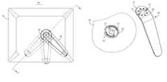
- FIG. 1is a back view of an electronic device according to an exemplary embodiment.
- FIG. 2is a schematic, isometric view of the electronic device of FIG. 1 , with a front cover and electronic elements removed.
- FIG. 3is an exploded view of the electronic device of FIG. 2 .
- FIG. 4is an enlarged view, showing a support and a part of a back cover of the electronic device of FIG. 1 .
- FIG. 5is a partial, section view of the electronic device, taken along the line A-A of FIG. 1 .
- the electronic device 10includes a back cover 20 and a support 30 .
- the support 30is pivoted to the back cover 20 by a pivot shaft 40 .
- the pivot shaft 40is a screw.
- the support 30is an elongated plate bent at one end thereof.
- the bent endforms a contact area 32 .
- a through hole 33is defined in the contact area 32 .
- a plurality of positioning holes 34 and two protrusions 35are disposed around the through hole 33 .
- the back cover 20defines a contact area 22 on an outer surface thereof.
- the contact area 22contacts the contact area 32 of the support 30 when assembled.
- a through hole 23is defined in the contact area 22 .
- Two step through holes 24 corresponding to the positioning holes 34 and two arc-shaped limiting grooves 25 corresponding to the protrusions 35are defined in and disposed around the through hole 23 .
- the back cover 20further includes two hooks 26 projected from an inner surface thereof.
- the electronic device 10further includes two retractable spring balls 70 , a nut 60 , and an overlay 50 .
- Each spring ball 70includes a spring 71 and a rod 72 .
- the rod 72is round head and includes a flange extended on a middle portion thereof.
- the support 30if the support 30 receives a rotary force, the support 30 pushes the rods 72 to slide out of the positioning holes 34 , and the springs 71 are compressed at this time, thereby the support 30 rotates around the screw 40 . Once the rotary force is withdrawn, the springs 71 rebound and push the rods 72 to slide into the positioning holes 34 , thus to prevent the support 30 from continued rotation. As the support 30 has a plurality of positioning holes 34 , the support 30 can stay at various positions.
Landscapes
- Engineering & Computer Science (AREA)
- General Engineering & Computer Science (AREA)
- Mechanical Engineering (AREA)
- Pivots And Pivotal Connections (AREA)
- Casings For Electric Apparatus (AREA)
Abstract
Description
1. Technical Field
The present disclosure relates to an electronic device with a support.
2. Description of Related Art
Electronic devices, for example, digital photo frames, usually have supports. One kind of support is one that is non-rotatably fixed to an electronic device. Another kind of the support is one that is rotatably fixed on the electronic device, but has only two positions available.
What is needed is an electronic device with a multi-angle positioning support.
The elements in the drawings are not necessarily drawn to scale, the emphasis instead being placed upon clearly illustrating the principles of the present disclosure. Moreover, in the drawings, like reference numerals designate corresponding parts throughout the several views.
Referring toFIGS. 1 and 2 , anelectronic device 10 according to an exemplary embodiment is disclosed. Theelectronic device 10 includes aback cover 20 and asupport 30. Thesupport 30 is pivoted to theback cover 20 by apivot shaft 40. In this embodiment, thepivot shaft 40 is a screw.
Referring toFIG. 4 , thesupport 30 is an elongated plate bent at one end thereof. The bent end forms acontact area 32. A throughhole 33 is defined in thecontact area 32. A plurality ofpositioning holes 34 and twoprotrusions 35 are disposed around the throughhole 33.
Theback cover 20 defines acontact area 22 on an outer surface thereof. Thecontact area 22 contacts thecontact area 32 of thesupport 30 when assembled. A throughhole 23 is defined in thecontact area 22. Two step throughholes 24 corresponding to thepositioning holes 34 and two arc-shapedlimiting grooves 25 corresponding to theprotrusions 35 are defined in and disposed around the throughhole 23. Referring toFIG. 5 , theback cover 20 further includes twohooks 26 projected from an inner surface thereof.
Referring toFIG. 3 , theelectronic device 10 further includes tworetractable spring balls 70, anut 60, and anoverlay 50. Eachspring ball 70 includes aspring 71 and arod 72. Referring toFIG. 5 , therod 72 is round head and includes a flange extended on a middle portion thereof.
Referring toFIGS. 3 ,4, and5 at the same time, to assemble theelectronic device 10, first, let thescrew 40 extend through theholes nut 60, thus to connect thesupport 30 to theback cover 20, and let the arc-shaped grooves 25 of theback cover 20 receive theprotrusions 35 of thesupport 30. Second, let therods 72 of thespring balls 70 extend through thestep holes 24 of theback cover 20, the flanges of therods 72 resist against the steps of thestep holes 24, and the round heads of therods 72 enter into thepositioning holes 34 of thesupport 30, and let thesprings 71 of thespring balls 70 resiliently support therods 72. Finally, let theoverlay 50 receive thesprings 71, and thehooks 26 of theback cover 20 engage theoverlay 50.
Referring toFIGS. 1 ,4, and5, if thesupport 30 receives a rotary force, thesupport 30 pushes therods 72 to slide out of thepositioning holes 34, and thesprings 71 are compressed at this time, thereby thesupport 30 rotates around thescrew 40. Once the rotary force is withdrawn, thesprings 71 rebound and push therods 72 to slide into thepositioning holes 34, thus to prevent thesupport 30 from continued rotation. As thesupport 30 has a plurality ofpositioning holes 34, thesupport 30 can stay at various positions.
When thesupport 30 rotates around thescrew 40, theprotrusions 35 of thesupport 30 slide in the arc-shaped grooves 25 of theback cover 20, thus, a sector angle of the arc-shaped grooves 25 determines a rotation range of thesupport 30.
Moreover, it is to be understood that the invention may be embodied in other forms without departing from the spirit thereof. Thus, the present examples and embodiments are to be considered in all respects as illustrative and not restrictive, and the invention is not to be limited to the details given herein.
Claims (14)
1. An electronic device comprising:
a back cover defining a first contact area;
a support pivoted to the back cover by a pivot shaft, wherein the support defines a second contact area contacting the first contact area, and a plurality of positioning holes are defined in and disposed on the second contact area around the pivot shaft; and
at least one retractable spring ball projected from the first contact area of the back cover, configured for cooperating with the positioning holes of the support;
wherein when the support rotates, the at least one retractable spring ball slides out of a corresponding one of the positioning holes, and when the support is at rest, the at least one retractable spring ball slides into a corresponding one of the positioning holes to maintain position of the support.
2. The electronic device ofclaim 1 , further comprising protrusions projected from the second contact area, and arc-shaped grooves defined in the first contact area for receiving the protrusions.
3. The electronic device ofclaim 2 , wherein the pivot shaft is a screw.
4. The electronic device ofclaim 3 , further comprising a nut engaging with the pivot shaft.
5. The electronic device ofclaim 2 , further comprising an overlay for fixing the spring balls on the back cover.
6. The electronic device ofclaim 5 , wherein the back cover comprises hooks for fixing the overlay.
7. The electronic device ofclaim 2 , wherein the support is an elongated plate bent at one end.
8. The electronic device ofclaim 2 , wherein the at least one retractable spring ball comprises two retractable spring balls.
9. The electronic device ofclaim 1 , wherein the pivot shaft is a screw.
10. The electronic device ofclaim 9 , further comprising a nut engaging with the pivot shaft.
11. The electronic device ofclaim 1 , further comprising an overlay for fixing the spring balls on the back cover.
12. The electronic device ofclaim 11 , wherein the back cover comprises hooks for fixing the overlay.
13. The electronic device ofclaim 1 , wherein the support is an elongated plate bent at one end.
14. The electronic device ofclaim 1 , wherein the at least one retractable spring ball comprises two retractable spring balls.
Applications Claiming Priority (3)
| Application Number | Priority Date | Filing Date | Title |
|---|---|---|---|
| CN200810302757 | 2008-07-16 | ||
| CN200810302757.0 | 2008-07-16 | ||
| CN2008103027570ACN101629671B (en) | 2008-07-16 | 2008-07-16 | Electronic device with multi-angle positioning support |
Publications (2)
| Publication Number | Publication Date |
|---|---|
| US20100012809A1 US20100012809A1 (en) | 2010-01-21 |
| US7744055B2true US7744055B2 (en) | 2010-06-29 |
Family
ID=41529453
Family Applications (1)
| Application Number | Title | Priority Date | Filing Date |
|---|---|---|---|
| US12/421,655Expired - Fee RelatedUS7744055B2 (en) | 2008-07-16 | 2009-04-10 | Electronic device with multi-angle positioning support |
Country Status (2)
| Country | Link |
|---|---|
| US (1) | US7744055B2 (en) |
| CN (1) | CN101629671B (en) |
Cited By (23)
| Publication number | Priority date | Publication date | Assignee | Title |
|---|---|---|---|---|
| US20110017898A1 (en)* | 2009-07-24 | 2011-01-27 | Hannstar Display Corporation Ltd. | Stand and electronic device using the same |
| US20110025176A1 (en)* | 2009-07-29 | 2011-02-03 | Apple Inc. | Multiple Position Stand |
| US20110031287A1 (en)* | 2008-09-09 | 2011-02-10 | Zero Chroma, LLC | Holder for Electronic Device with Support |
| US20120236475A1 (en)* | 2011-03-16 | 2012-09-20 | Hon Hai Precision Industry Co., Ltd. | Digital photo frame |
| US20120275094A1 (en)* | 2011-04-28 | 2012-11-01 | Hon Hai Precision Industry Co., Ltd. | Supporting mechanism and electronic device |
| US20130107473A1 (en)* | 2011-10-28 | 2013-05-02 | Hon Hai Precision Industry Co., Ltd. | Electronic device capable of adjusting orientation of display content in response to rotation of a support |
| USD687439S1 (en)* | 2012-08-14 | 2013-08-06 | Us Plus You, LLC | Tablet computer stand |
| USD687441S1 (en)* | 2012-10-04 | 2013-08-06 | Tony H. Janzen | Locking tablet support |
| US20140014802A1 (en)* | 2012-07-16 | 2014-01-16 | Chun-Cheng Liu | Support device |
| USD698543S1 (en)* | 2012-10-19 | 2014-02-04 | Zerochroma, LLC | Portion of holder for electronic device |
| US8960634B2 (en) | 2008-09-09 | 2015-02-24 | Zero Chroma, LLC | Holder for electronic device with support |
| US20150272352A1 (en)* | 2014-03-25 | 2015-10-01 | Art Forth Llc | System and method for rotatably mounting a picture frame |
| US9152172B1 (en)* | 2011-01-18 | 2015-10-06 | Z124 | Spheroidal pivot for an electronic device |
| US20150288405A1 (en)* | 2014-04-07 | 2015-10-08 | Logitech Europe S.A. | Portable electronic device support |
| US20150345700A1 (en)* | 2012-10-10 | 2015-12-03 | Paul-Henri Robert | Holding accessory to assist with manipulating a portable electronic device of the touch-screen tablet type |
| USD751813S1 (en)* | 2009-09-09 | 2016-03-22 | Zero Chroma, LLC | Portion of holder for electronic device |
| US9470358B2 (en)* | 2013-05-03 | 2016-10-18 | Zero Chroma Llc | Electronic device holder with repositionable stand and systems and methods thereof |
| USD800734S1 (en)* | 2016-09-21 | 2017-10-24 | Fred Lewis | Tablet stand |
| US20200153472A1 (en)* | 2015-12-04 | 2020-05-14 | Joseph Anthony Zaloom | Inconspicuous Suspension System for Suspending Mobile Computing Devices to Multiple Angles and Orientations with Respect to a Resting Surface or Base |
| US11317526B2 (en)* | 2019-08-05 | 2022-04-26 | Asustek Computer Inc. | Electronic device and display thereof |
| US11500426B2 (en)* | 2021-03-23 | 2022-11-15 | Lenovo (Singapore) Pte. Ltd. | Display system |
| USD1002634S1 (en)* | 2021-11-24 | 2023-10-24 | Landleben Designs LLC | Inclined tablet display stand |
| USD1020764S1 (en)* | 2021-11-24 | 2024-04-02 | Landleben Designs LLC | Upright tablet display stand |
Families Citing this family (12)
| Publication number | Priority date | Publication date | Assignee | Title |
|---|---|---|---|---|
| TWI336227B (en)* | 2007-07-27 | 2011-01-11 | Compal Electronics Inc | Rotatable support mechanism and electronic device using the same |
| TWI335969B (en)* | 2007-11-21 | 2011-01-11 | Compal Electronics Inc | Adjustable supporting mechanism and electronic apparatus |
| US8616508B1 (en)* | 2010-09-16 | 2013-12-31 | Jesse D. Coleman | Tripod adapter for hand-held mobile media devices |
| CN102606858B (en)* | 2011-01-25 | 2015-10-14 | 富泰华工业(深圳)有限公司 | Supporting frame and the electronic equipment with supporting frame |
| US20120312955A1 (en)* | 2011-06-08 | 2012-12-13 | Randolph Ovie L | Handle for hand held device |
| US9760116B2 (en)* | 2012-12-05 | 2017-09-12 | Mobile Tech, Inc. | Docking station for tablet device |
| CN105045340B (en)* | 2015-07-09 | 2018-09-07 | 苏州硅果电子有限公司 | It is a kind of can multi-faceted adjusting tablet computer |
| CN105805502B (en) | 2016-04-15 | 2019-01-22 | 京东方科技集团股份有限公司 | A vertical and horizontal fixed bracket |
| US10101770B2 (en) | 2016-07-29 | 2018-10-16 | Mobile Tech, Inc. | Docking system for portable computing device in an enclosure |
| WO2020075772A1 (en)* | 2018-10-09 | 2020-04-16 | 陽斗子 是枝 | Portable communication terminal equipment case |
| US11892235B2 (en)* | 2020-11-12 | 2024-02-06 | CEMM Canada Limited | Method and system for processing natural gas |
| JP1736106S (en) | 2022-08-03 | 2023-02-03 | Multifunction bar for mobile devices |
Citations (6)
| Publication number | Priority date | Publication date | Assignee | Title |
|---|---|---|---|---|
| US5329712A (en)* | 1990-09-09 | 1994-07-19 | Licinvest Ag | Frame for the display of pictures |
| US5933996A (en)* | 1998-12-14 | 1999-08-10 | Fanthing Electrical Corp. | Photograph frame assembly with a slidable and rotatable supporting member |
| US6971622B2 (en)* | 2001-02-15 | 2005-12-06 | Agilent Technologies, Inc. | Supporting device for a portable device |
| US20070062089A1 (en)* | 2005-08-31 | 2007-03-22 | Homer Steven S | Display device |
| US20070089344A1 (en)* | 2005-10-07 | 2007-04-26 | Chin-Chieh Yeh | Inserting engaging frame for photos |
| US7301759B2 (en)* | 2004-05-26 | 2007-11-27 | Silicon Electron Pyrimid Ltd. | Portable electronic product with a bracket |
Family Cites Families (8)
| Publication number | Priority date | Publication date | Assignee | Title |
|---|---|---|---|---|
| US1115450A (en)* | 1913-02-20 | 1914-10-27 | Frank Parizek | Hinge. |
| US4832299A (en)* | 1987-12-04 | 1989-05-23 | Pacesetter Infusion, Ltd. | Clamp fixture |
| US5143468A (en)* | 1991-04-05 | 1992-09-01 | General Resource Corporation | Articulable joint and support frame for exhaust hose |
| CN2200826Y (en)* | 1994-07-12 | 1995-06-14 | 郑州大学 | Directional antenna turning device of underground metal lead-out detector |
| US6086207A (en)* | 1998-12-08 | 2000-07-11 | Chapman/Leonard Studio Equipment | Camera leveling head |
| CN2603173Y (en)* | 2002-11-30 | 2004-02-11 | 中山市雅立洁具有限公司 | Multi-section limit door shaft structure |
| CN201018587Y (en)* | 2007-03-02 | 2008-02-06 | 吴槐 | Rotary pedestal for TV set |
| CN201262304Y (en)* | 2008-07-18 | 2009-06-24 | 鸿富锦精密工业(深圳)有限公司 | Electronics with multi-angle positioning bracket |
- 2008
- 2008-07-16CNCN2008103027570Apatent/CN101629671B/ennot_activeExpired - Fee Related
- 2009
- 2009-04-10USUS12/421,655patent/US7744055B2/ennot_activeExpired - Fee Related
Patent Citations (6)
| Publication number | Priority date | Publication date | Assignee | Title |
|---|---|---|---|---|
| US5329712A (en)* | 1990-09-09 | 1994-07-19 | Licinvest Ag | Frame for the display of pictures |
| US5933996A (en)* | 1998-12-14 | 1999-08-10 | Fanthing Electrical Corp. | Photograph frame assembly with a slidable and rotatable supporting member |
| US6971622B2 (en)* | 2001-02-15 | 2005-12-06 | Agilent Technologies, Inc. | Supporting device for a portable device |
| US7301759B2 (en)* | 2004-05-26 | 2007-11-27 | Silicon Electron Pyrimid Ltd. | Portable electronic product with a bracket |
| US20070062089A1 (en)* | 2005-08-31 | 2007-03-22 | Homer Steven S | Display device |
| US20070089344A1 (en)* | 2005-10-07 | 2007-04-26 | Chin-Chieh Yeh | Inserting engaging frame for photos |
Cited By (36)
| Publication number | Priority date | Publication date | Assignee | Title |
|---|---|---|---|---|
| US8960634B2 (en) | 2008-09-09 | 2015-02-24 | Zero Chroma, LLC | Holder for electronic device with support |
| US20110031287A1 (en)* | 2008-09-09 | 2011-02-10 | Zero Chroma, LLC | Holder for Electronic Device with Support |
| US9538675B2 (en) | 2008-09-09 | 2017-01-03 | Zero Chroma, Llc. | Holder for electronic device with support |
| US8382059B2 (en)* | 2008-09-09 | 2013-02-26 | Zero Chroma, LLC | Holder for electronic device with support |
| US9267638B2 (en) | 2008-09-09 | 2016-02-23 | Zero Chroma, LLC | Holder for electronic device with support |
| US8356790B2 (en)* | 2009-07-24 | 2013-01-22 | Hannstar Display Corporation Ltd. | Stand and electronic device using the same |
| US20110017898A1 (en)* | 2009-07-24 | 2011-01-27 | Hannstar Display Corporation Ltd. | Stand and electronic device using the same |
| US20110025176A1 (en)* | 2009-07-29 | 2011-02-03 | Apple Inc. | Multiple Position Stand |
| US8118274B2 (en)* | 2009-07-29 | 2012-02-21 | Apple Inc. | Multiple position stand |
| USD751813S1 (en)* | 2009-09-09 | 2016-03-22 | Zero Chroma, LLC | Portion of holder for electronic device |
| US9152172B1 (en)* | 2011-01-18 | 2015-10-06 | Z124 | Spheroidal pivot for an electronic device |
| US9152263B1 (en) | 2011-01-18 | 2015-10-06 | Z124 | Spheroidal pivot for an electronic device |
| US9152171B1 (en) | 2011-01-18 | 2015-10-06 | Z124 | Spheroidal pivot for an electronic device |
| US8520371B2 (en)* | 2011-03-16 | 2013-08-27 | Hong Fu Jin Precision Industry (Shenzhen) Co., Ltd. | Digital photo frame |
| US20120236475A1 (en)* | 2011-03-16 | 2012-09-20 | Hon Hai Precision Industry Co., Ltd. | Digital photo frame |
| US20120275094A1 (en)* | 2011-04-28 | 2012-11-01 | Hon Hai Precision Industry Co., Ltd. | Supporting mechanism and electronic device |
| US8599570B2 (en)* | 2011-10-28 | 2013-12-03 | Hong Fu Jin Precision Industry (Shenzhen) Co., Ltd. | Electronic device capable of adjusting orientation of display content in response to rotation of a support |
| US20130107473A1 (en)* | 2011-10-28 | 2013-05-02 | Hon Hai Precision Industry Co., Ltd. | Electronic device capable of adjusting orientation of display content in response to rotation of a support |
| US8939422B2 (en)* | 2012-07-16 | 2015-01-27 | Wistron Corporation | Support device |
| US20140014802A1 (en)* | 2012-07-16 | 2014-01-16 | Chun-Cheng Liu | Support device |
| USD687439S1 (en)* | 2012-08-14 | 2013-08-06 | Us Plus You, LLC | Tablet computer stand |
| USD687441S1 (en)* | 2012-10-04 | 2013-08-06 | Tony H. Janzen | Locking tablet support |
| US20150345700A1 (en)* | 2012-10-10 | 2015-12-03 | Paul-Henri Robert | Holding accessory to assist with manipulating a portable electronic device of the touch-screen tablet type |
| USD698543S1 (en)* | 2012-10-19 | 2014-02-04 | Zerochroma, LLC | Portion of holder for electronic device |
| US9470358B2 (en)* | 2013-05-03 | 2016-10-18 | Zero Chroma Llc | Electronic device holder with repositionable stand and systems and methods thereof |
| US20150272352A1 (en)* | 2014-03-25 | 2015-10-01 | Art Forth Llc | System and method for rotatably mounting a picture frame |
| US9427098B2 (en)* | 2014-03-25 | 2016-08-30 | Art Forth Llc | System and method for rotatably mounting a picture frame |
| US20150288405A1 (en)* | 2014-04-07 | 2015-10-08 | Logitech Europe S.A. | Portable electronic device support |
| US10063268B2 (en)* | 2014-04-07 | 2018-08-28 | Logitech Europe S.A. | Portable electronic device support |
| US20200153472A1 (en)* | 2015-12-04 | 2020-05-14 | Joseph Anthony Zaloom | Inconspicuous Suspension System for Suspending Mobile Computing Devices to Multiple Angles and Orientations with Respect to a Resting Surface or Base |
| US10700726B2 (en)* | 2015-12-04 | 2020-06-30 | Joseph A. Zaloom | Inconspicuous suspension system for suspending mobile computing devices to multiple angles and orientations with respect to a resting surface or base |
| USD800734S1 (en)* | 2016-09-21 | 2017-10-24 | Fred Lewis | Tablet stand |
| US11317526B2 (en)* | 2019-08-05 | 2022-04-26 | Asustek Computer Inc. | Electronic device and display thereof |
| US11500426B2 (en)* | 2021-03-23 | 2022-11-15 | Lenovo (Singapore) Pte. Ltd. | Display system |
| USD1002634S1 (en)* | 2021-11-24 | 2023-10-24 | Landleben Designs LLC | Inclined tablet display stand |
| USD1020764S1 (en)* | 2021-11-24 | 2024-04-02 | Landleben Designs LLC | Upright tablet display stand |
Also Published As
| Publication number | Publication date |
|---|---|
| CN101629671A (en) | 2010-01-20 |
| US20100012809A1 (en) | 2010-01-21 |
| CN101629671B (en) | 2012-05-30 |
Similar Documents
| Publication | Publication Date | Title |
|---|---|---|
| US7744055B2 (en) | Electronic device with multi-angle positioning support | |
| US6845546B1 (en) | Hinge assembly with a rotation seat available to rotate in both latitudinal and longitudinal directions with respect to a fixing seat | |
| US7762504B2 (en) | Base for display device | |
| US6666422B1 (en) | Foldable hinge bracket for a laptop computer | |
| US20080034549A1 (en) | Hinge structure | |
| US8103034B2 (en) | Mounting device and speaker assembly having the same | |
| US8291549B2 (en) | Hinge mechanism | |
| US20130168288A1 (en) | Support for portable computing device | |
| US9448583B1 (en) | Electronic device and hinge assembly | |
| US8250709B2 (en) | Rotating mechanism for an electronic device and an electronic device with the same | |
| US20050116135A1 (en) | Mounting apparatus for storage device | |
| US20140167585A1 (en) | Rotating mechanism and electronic device with same | |
| US20110061198A1 (en) | Rolling device | |
| US20100071156A1 (en) | Hinge assembly | |
| US9436228B2 (en) | Fixing mechanism with quick-releasing function and related electronic device | |
| US20060210060A1 (en) | Opening/closing device | |
| US8477486B2 (en) | Linkage mechanism and electronic device using same | |
| CN101453852A (en) | Lifting mechanism | |
| US8079166B2 (en) | Support assembly and digital photo frame using the same | |
| US20100226089A1 (en) | Hinge assembly and electronic device using the same | |
| TW201139822A (en) | Apparatus for securing a portable electronic device | |
| CN103851314A (en) | Rotating mechanism and display device with same | |
| US20110007454A1 (en) | Electronic device frame with support mechanism | |
| US9386721B2 (en) | Fixing device for sliding mechanism | |
| US7913360B2 (en) | Hinge |
Legal Events
| Date | Code | Title | Description |
|---|---|---|---|
| AS | Assignment | Owner name:HONG FU JIN PRECISION INDUSTRY (SHENZHEN) CO., LTD Free format text:ASSIGNMENT OF ASSIGNORS INTEREST;ASSIGNORS:ZENG, YONG-QING;TANG, GAO-HUI;TANG, CHIANG-KUO;AND OTHERS;SIGNING DATES FROM 20090325 TO 20090326;REEL/FRAME:022530/0905 Owner name:HON HAI PRECISION INDUSTRY CO., LTD.,TAIWAN Free format text:ASSIGNMENT OF ASSIGNORS INTEREST;ASSIGNORS:ZENG, YONG-QING;TANG, GAO-HUI;TANG, CHIANG-KUO;AND OTHERS;SIGNING DATES FROM 20090325 TO 20090326;REEL/FRAME:022530/0905 | |
| REMI | Maintenance fee reminder mailed | ||
| LAPS | Lapse for failure to pay maintenance fees | ||
| STCH | Information on status: patent discontinuation | Free format text:PATENT EXPIRED DUE TO NONPAYMENT OF MAINTENANCE FEES UNDER 37 CFR 1.362 | |
| FP | Lapsed due to failure to pay maintenance fee | Effective date:20140629 |