US7743029B2 - Log configuration and online deployment services - Google Patents
Log configuration and online deployment servicesDownload PDFInfo
- Publication number
- US7743029B2 US7743029B2US10/836,851US83685104AUS7743029B2US 7743029 B2US7743029 B2US 7743029B2US 83685104 AUS83685104 AUS 83685104AUS 7743029 B2US7743029 B2US 7743029B2
- Authority
- US
- United States
- Prior art keywords
- logging
- enterprise
- component
- deployment
- log
- Prior art date
- Legal status (The legal status is an assumption and is not a legal conclusion. Google has not performed a legal analysis and makes no representation as to the accuracy of the status listed.)
- Active, expires
Links
Images


Classifications
- G—PHYSICS
- G06—COMPUTING OR CALCULATING; COUNTING
- G06F—ELECTRIC DIGITAL DATA PROCESSING
- G06F11/00—Error detection; Error correction; Monitoring
- G06F11/36—Prevention of errors by analysis, debugging or testing of software
- G06F11/362—Debugging of software
- G06F11/3636—Debugging of software by tracing the execution of the program
Definitions
- Loggingis employed within virtually all data networks. “Logging” refers generally to recording network-related and/or application-related information in response to one or more predefined network/application events. For example, when an end-user opens a TCP connection to a server, or unsuccessfully attempts to gain access to network resources (e.g., by attempting to log in to a particular server), this information is typically recorded as an entry within a log file. Similarly, if a variable within an application rises above a specified threshold value, a log entry indicating the value and the date and time that the threshold value was exceeded may be stored within a log file. Logging techniques may be employed to record any specified network/application event. Network administrators may then review the log files to identify security issues and/or troubleshoot network problems.
- J2EEJava 2 Enterprise Edition
- J2EEJava 2 Enterprise Edition
- J2EEreduces the costs and complexity associated with developing multi-tier enterprise services.
- Another advantage of J2EEis that it can be relatively rapidly deployed and enhanced as the need arises. J2EE is currently used in many large-scale application development projects for these reasons.
- Loggingcan be a very useful debugging tool to isolate problems, for example, by tracking each stage of the application being evaluated.
- loggingis configured via a logging configuration file.
- the logging configuration filetypically shared by multiple components being deployed. As enterprise applications increase in size and scope, the logging configuration file becomes more complicated and difficult to manage, resulting in a lack of scalability when deploying large numbers of application components.
- a logging configuration processin response to a request for deploying an enterprise component, extracts logging configuration information from a logging configuration file associated with the enterprise component and configures logging for the respective enterprise component being deployed. Thereafter, the deployment information of the enterprise component is logged based on the extracted logging configuration information when the enterprise component is deployed.
- FIG. 1is a block diagram illustrating an exemplary logging system according to one embodiment of the invention.
- FIG. 2is a block diagram illustrating an exemplary logging system according to another embodiment of the invention.
- FIG. 3is a block diagram illustrating an exemplary enterprise system according to one embodiment of the invention.
- FIG. 4is a flow diagram illustrating an exemplary process for deploying and configuring logging of an enterprise component according to one embodiment of the invention.
- FIG. 5is a flow diagram illustrating an exemplary process for configuring logging for an enterprise component being deployed, according to one embodiment of the invention.
- FIG. 6is block diagram of an exemplary structure of a log configuration file according to one embodiment of the invention.
- FIG. 7is an example of a configuration file in an XML format according to one embodiment of the invention.
- FIG. 8is a block diagram illustrating an exemplary graphical user interface (GUI) for generating a logging configuration file according to one embodiment of the invention.
- GUIgraphical user interface
- FIG. 9is a block diagram illustrating an exemplary graphical user interface (GUI) for configuring logging according to one embodiment of the invention.
- GUIgraphical user interface
- FIG. 10is a block diagram illustrating an exemplary graphical user interface (GUI) in accordance with an embodiment of the invention.
- GUIgraphical user interface
- FIG. 11illustrates an exemplary a standalone log viewer GUI according to one embodiment of the invention.
- FIG. 12is a block diagram of a data processing system which may be used with one embodiment of the invention.
- each of the enterprise components being deployedis associated with a configuration file.
- the configuration filemay be designed exclusively for the respective enterprise component being deployed and used to configure the logging of the respective enterprise component.
- the configuration filemay be written as a metadata file, such as, for example, an XML (extensible mark-up language) file.
- the present inventionalso relates to apparatus for performing the operations herein.
- This apparatusmay be specially constructed for the required purposes, or it may comprise a general purpose computer selectively activated or reconfigured by a computer program stored in the computer.
- a computer programmay be stored in a computer readable storage medium, such as, but is not limited to, any type of disk including floppy disks, optical disks, CD-ROMs, and magnetic-optical disks, read-only memories (ROMs), random access memories (RAMs), erasable programmable ROMs (EPROMs), electrically erasable programmable ROMs (EEPROMs), magnetic or optical cards, or any type of media suitable for storing electronic instructions, and each coupled to a computer system bus.
- ROMsread-only memories
- RAMsrandom access memories
- EPROMserasable programmable ROMs
- EEPROMselectrically erasable programmable ROMs
- magnetic or optical cardsor any type of media suitable for storing electronic instructions, and each coupled to
- a machine-readable mediumincludes any mechanism for storing or transmitting information in a form readable by a machine (e.g., a computer).
- a machine-readable mediumincludes read only memory (“ROM”); random access memory (“RAM”); magnetic disk storage media; optical storage media; flash memory devices; electrical, optical, acoustical or other form of propagated signals (e.g., carrier waves, infrared signals, digital signals, etc.); etc.
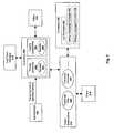
- FIG. 1is a block diagram illustrating an exemplary logging system according to one embodiment of the invention.
- the exemplary logging system 100includes a log manager 102 coupled to one or more log controllers 104 (one shown in FIG. 1 , but the “N” markings in FIG. 1 indicate possible presence of N items).
- the log manager 102manages the log controllers 104 .
- the log manager 102is part of the kernel of an enterprise engine, such as, for example, a J2EE Engine, and is started at system startup.
- the log managerconfigures the logging controllers for the kernel based on one or more configuration files.
- the log managermay also provide support for storing system critical logs in a database.
- configuration filesmay be created specifically for a specific deployable component.
- the configuration filesmay be written in as metadata files, such as for example, XML or HTML files.
- some or all of the deployable componentsmay be packaged with at least one configuration file for configuring the logging and/or tracing when the respective component is deployed.
- a log controller 104may receive messages from executing application (e.g., applications 101 ).
- the log controllermay be defined as a Java class having two subclasses or modules such as “category” to generate log messages and “location” to generate trace messages. Tracing involves the reconstruction of the control flow of an executing application, which may be used during program development and testing or problem detection, in productive systems (i.e., as an alternative to debugging). Tracing may be switched off during normal operation. Moreover, trace messages may be emitted to locations, which describe delimited code areas such as packages or classes.
- Loggingmay be used to record normal or exceptional events that occur during program execution and this may be switched on during normal operation.
- the log messagesmay be emitted to categories, which describe distinguished problem areas such as database problems or security auditing. In an embodiment of the invention, log messages are also visible in a trace.
- logstypically are addressed to an administrator of a running system while traces typically are addressed to a developer and/or support organization.
- the developermay decide whether a message is a log message or trace message.
- the logging system 100further includes a log (also referred to as a destination) 106 coupled to each of the log controllers 104 .
- the log 106may represent the destination to which the message received by the respective log controller should be sent (or otherwise published).
- the log 106is coupled to a formatter 108 , which determines the format of the message to be published.
- a message passed through the logging system 100may include a log record or potion thereof.
- the log recordmay be a structure that holds at best a portion of a message and data corresponding thereto.
- the log recordmay include severity information regarding the message, for example, to indicate the importance (severity) of the message.
- a severity thresholdmay be set and only a message with an assigned severity that is more severe than this threshold may be recorded and/or published.
- the logging system 100optionally includes one or more filters 103 and 105 for the log controllers 104 and log 106 respectively, to further screen out the messages.
- FIG. 2is a block diagram illustrating an exemplary logging system according to another embodiment of the invention.
- the exemplary architectureincludes a plurality of controllers 200 managed by a log/trace manager 210 .
- the controllers 200are configured to process trace/logging events generated by a plurality of different applications 201 .
- the term “application”is used broadly to refer to any type of program code executed on a computer and/or transmitted over a network (e.g., using a particular network protocol).
- each controller 200is an instance of a defined “controller” class (e.g., a Java class) which includes two sub-classes, a “tracing” sub-class and a “logging” sub-class (described in detail below), which provide features specific to tracing and logging operations, respectively.
- the tracing controller 202 illustrated in FIG. 2represents an instance of the tracing sub-class
- the logging controller 204represents an instance of the logging sub-class.
- tracing controllers 202are associated with program code locations (e.g., locations within packages, classes, . . . etc)
- logging controllers 204are associated with system categories (e.g., logical system categories such as database, network, . . . etc).
- the controller classprovides methods for associating log/trace output destinations with specific controllers 200 and for controlling the actual writing of log/trace messages.
- a methodWhen a method is called, the writing of the log/trace message to a log/trace file 220 , console 221 or other output destination 214 depends on the severity level associated with the message, the severity settings 205 , 206 of the relevant controller(s) 200 , and the filtering configuration of one or more optional filters 212 and 216 .
- messages having a severity level greater than or equal to the effective severity of the relevant controller 200are candidates for output and are forwarded to the output destinations 214 attached to the controller 200 (i.e., assuming that the messages are not filtered by one of the filters 212 , 216 ).
- filters 212 associated with the controller 200may filter the messages based on predefined filtering criteria.
- a filter 212may be assigned to filter messages directed to the file, thereby limiting output to the console only.
- filtersmay be associated with particular log controllers 200 and/or with specific output destinations 214 (e.g., specific log/trace files).
- filtersmay be associated with both controllers 200 and/or output destinations 214 to further restrict or alter the output tracing and logging behavior.
- multiple filters having different filtering criteriamay be allocated to each controller 200 and/or destination 214 . Further detailed information concerning the logging architecture may be found in the above-identified co-pending U.S. patent applications.
- One embodiment of the inventionis implemented in an object-oriented programming environment such as Java (e.g., within a J2EE platform/engine).
- object-oriented programming environmentsuch as Java (e.g., within a J2EE platform/engine).
- each of the modules illustrated in FIG. 2are represented by objects and/or classes.
- the classes and/or objects of this embodimentcomprise an application programming interface (“API”) usable to configure logging and/or tracing operations within a Java environment.
- APIapplication programming interface
- object-oriented programming environmentssuch as, for example, the .NET frameworks defined by Microsoft (e.g., using C# and/or Visual Basic.NET, etc.), may be utilized.
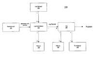
- FIG. 3is a block diagram illustrating an exemplary enterprise system according to one embodiment of the invention.
- exemplary system 300includes, but is not limited to, an enterprise engine 301 and one or more enterprise components 302 - 304 deployable by the enterprise engine 301 .
- Each of the deployable enterprise components 302 - 304includes a corresponding configuration file 309 - 311 .
- each of the configuration filesis designed specifically for the respective enterprise component.
- configuration files 309 - 311are specifically designed for the respective enterprise components 302 - 304 .
- the enterprise engine 301includes, but is not limited to, a logging module 307 and a repository 308 for temporarily storing the log configuration.
- the repository 308may be implemented as a part of a system memory of the enterprise engine 301 .
- the logging module 307may include one or more processes executed by an operating system within the enterprise engine 301 .
- the logging module 307may be a part of logging system implemented within the enterprise engine 301 , such as, for example, exemplary logging systems shown in FIGS. 1 and 2 .
- the configuration files 309 - 311may be created and edited using a variety of editors, such as, for example, a text editor or a word processor, etc.
- the configuration files 309 - 311may be created and edited via an integrated development environment (IDE), such as, for example, the exemplary IDE shown in FIG. 8 .
- IDEintegrated development environment
- the operating systemmay be a Windows operating system from Microsoft Corporation or a MacOS operating system from Apple Computer. Alternatively, the operating system may be a Unix, a Linux, or an embedded operating system from a variety of vendors.
- the enterprise engine 301may be implemented within a data processing system, such as, for example, exemplary system 1200 of FIG. 12 , which will be described in detail further below.
- the logging module 307extracts the logging configuration from the configuration file by parsing the configuration file according to certain predetermined formats and/or policies. Thereafter, the logging module processes the extracted logging configuration information and stores the processed configuration information in the repository 308 and/or database 306 . In addition, a copy of the corresponding configuration file may also be permanently stored in database 306 for later use.
- the systemthen may perform logging for the specific component during the deployment of the respective component according to the logging configuration of the respective component.
- the enterprise engine 301may include an administration API 315 to allow an administrator to configure the logging at run time after the initial configurations. The administrator 305 may then modify the logging configuration and update the corresponding configuration file stored in the database 306 .
- the exemplary enterprise engine 301may also include a log viewer 312 to allow a user to view the logged information.
- the log viewer 312may be integrated within the administration API 315 , such as, for example, log viewer 1000 shown in FIG. 10 .
- the log viewer 312may be standalone log view, such as, for example, log viewer 1100 shown in FIG. 11 .
- Other viewing mechanisms, such as a command line interface (CLI)may be utilized.
- the log viewer 312may be locally attached to the enterprise engine 301 .
- the log viewer 312may be communicatively coupled to the enterprise engine over a network.
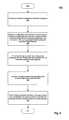
- FIG. 4is a flow diagram illustrating an exemplary process for deploying and configuring logging of an enterprise component according to one embodiment of the invention.
- Exemplary process 400may be performed by a processing logic that may include hardware (circuitry, dedicated logic, etc.), software (such as is run on a dedicated machine), or a combination of both.
- a deployment service 401is invoked.
- the deployment service 401may be invoked online by an enterprise engine, such as, for example, enterprise engine 301 of FIG. 3 .
- the deployment service 401is invoked, at block 403 , the enterprise component being deployed is passed to the deployment service 401 as an object.
- the deployment service 401recognizes the type of the enterprise component being deployed.
- the enterprise componentmay be, for example, an enterprise application, a library, a resource adapter, or a service.
- log configuration service 402provides, but not limited to, the following functionality:
- a configuration file associated with the enterprise componentsuch as configurations files 309 - 311 of FIG. 3
- the log configuration service 402extracts the logging configuration information from the configuration file.
- the logging informationis processed by the log configuration service 402 .
- one or more policiesmay be applied.
- the processed logging configuration informationis applied to the enterprise component being deployed.
- the processed logging configuration informationmay be stored in a location of the system memory, such as, for example, the repository 308 of FIG. 3 .
- a copy of the configuration informationmay also be stored in a database (e.g., database 306 of FIG. 3 ) for future use, which may be updated subsequently by an administrator.
- logging operationsare executed according to the logging configuration.
- the above configuration processesmay also be applied to the trace configuration that allows a developer to trace the task executions for the purposes of debugging.
- FIG. 5is a flow diagram illustrating an exemplary process for configuring logging for an enterprise component being deployed, according to one embodiment of the invention.
- Exemplary process 500may be performed by a processing logic that may include hardware (circuitry, dedicated logic, etc.), software (such as is run on a dedicated machine), or a combination of both.
- exemplary process 500includes, but is not limited to, extracting, in response to a request for deploying an enterprise component, logging configuration information from a logging configuration file associated with the enterprise component, the logging configuration file being designed exclusively for configuring logging of the enterprise component, and logging deployment information of the enterprise component based on the extracted logging configuration information when deploying the enterprise component.
- a request for deploying an enterprise component(e.g., enterprise components 302 - 304 of FIG. 3 ) is received.
- the request for deploymentmay be issued by an enterprise engine, such as, for example, a J2EE engine in a Java computing environment, or alternatively, a .NET framework engine.
- a deployment servicesuch as deployment service 401 of FIG. 4 may be invoked to handle the deployment request.
- the enterprise component being deployedmay be a library, a service, and/or an application of an enterprise server.
- the logging and/or tracing configurationis extracted from the configuration file associated with the enterprise component being deployed. For example, information related to the settings of log formatters, log destinations, and/or log controllers may be extracted from the configuration file.
- the logging and/or tracing of the enterprise componentare configured according to the extracted configuration information.
- logging and/or tracingare performed based on the configuration set up based on the configuration file associated with the deployed enterprise component. Other operations may be performed within the scope of embodiments of the invention.
- FIG. 6is block diagram of an exemplary structure of a log configuration file according to one embodiment of the invention.
- exemplary log configuration structure 600includes, but not limited to, one or more log formatters 601 , one or more log destinations 602 , and one or more log controllers 603 .
- Each of the log formatters 601 , log destinations 602 , and log controllers 603may further include one or more sub-structures, such as, for example, effective severity 606 and relative severity 607 .
- sub-structuressuch as, for example, effective severity 606 and relative severity 607 . Detailed descriptions for each of the sub-structures according to one embodiment are set out below in the Appendix of the present application.
- the configuration files described abovemay be written according to the exemplary log configuration structure 600 in a variety of formats.
- the configuration filemay be written as a metadata file, such as, for example, an XML or HTML format.
- the exemplary configuration structure 600may be used by an enterprise computing engine, such as, for example, a Java J2EE engine or a .NET framework engine.
- log formatter section 601may be processed by a formatter component of the logging module (e.g., logging module 307 of FIG. 3 ), such as, for example, formatters 218 of FIG. 2 .
- log destination section 602may be processed by a destination component of the logging module, such as, for example, output destinations 214 of FIG. 2 .
- the log controller section 603may be processed by a controller of the logging module, such as, for example, controllers 200 of FIG. 2 .
- the log destination 602may further optionally include one or more filters 604 .
- the log controller 603may further optionally include an optional filter 605 .
- Other sections or sub-sections apparent to those with ordinary skill in the artmay be included.
- FIG. 7is an example of a configuration file in an XML format according to one embodiment of the invention.
- the exemplary configuration fileis written in an XML format having the corresponding log configuration structure 700 including, but not limited to, one or more log formatters 701 , one or more log destinations 702 , and one or more log controllers 703 .
- the destinations 702 and log controllers 703may further include one or more filters 704 and 705 respectively.
- the exemplary XML configuration filemay be processed by a variety of enterprise computing engines, such as, for example, a J2EE engine in a Java computing environment or alternatively, a .NET framework engine from Microsoft.
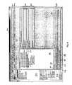
- FIG. 8is a block diagram illustrating an exemplary graphical user interface (GUI) for generating a logging configuration file according to one embodiment of the invention.
- GUIgraphical user interface
- the exemplary GUI 800may be included within a wizard designed to generate a logging configuration file.
- the GUI 800may be used to release or package a deployable component (e.g. components 302 - 304 of FIG. 3 ) by a release engineer, to generate and/or configure logging for each of the deployable components.
- a deployable componente.g. components 302 - 304 of FIG. 3
- GUI 800may be included within a development tool for developing enterprise applications.
- GUI 800may be a part of an integrated development environment (IDE) for developing Java enterprise applications (e.g., J2EE compatible applications), or alternatively, the exemplary GUI 800 may be part of other enterprise IDE, such as, for example, the .NET framework IDE.
- IDEintegrated development environment
- J2EE compatible applicationse.g., J2EE compatible applications
- the exemplary GUI 800may be part of other enterprise IDE, such as, for example, the .NET framework IDE.
- exemplary GUI 800includes, but not limited to, a tool bar 801 having one or more buttons or controls that when activated to perform certain tasks.
- the tool bar 801may include a button or control that when activated to generate a logging configuration file for each of the enterprise components being deployed.
- exemplary GUI 800includes a package window 804 to display a list of packages, where each package may include one or more deployable enterprise components.
- the exemplary GUI 800may include a property window 805 to list and edit one or more properties corresponding to respective package, such as, for example, package 818 listed in package window 804 .
- another window having one or more pagesmay be used to display information associated with the selected package.
- the one or more pagesmay be selected via one or more page selectors 802 .
- the one or more page selector 802includes a page selector 803 to select a page for configuring a logging configuration file.
- page 819when page selector 803 is activated, the corresponding page 819 for configuring a logging file is displayed.
- the page 819may also include one or more page selectors for configuring specific sections or pages of the logging configuration file.
- page 819may include a log formatter page selector 806 to configure log formatter section of the configuration file (e.g., formatter section 601 of FIG. 6 ), a log destination page selector 807 to configure log destination section of the configuration file (e.g., destination section 602 of FIG. 6 ), a log controller page selector 808 to configure log controller section of the configuration file (e.g., log controller section 603 of FIG. 6 ), and other sections, such as, source 809 .
- log formatter page selector 806to configure log formatter section of the configuration file (e.g., formatter section 601 of FIG. 6 )
- log destination page selector 807to configure log destination section of the configuration file (e.g., destination section 602 of FIG. 6
- page 810when log controller page selector 808 is activated, its corresponding page 810 is displayed.
- page 810includes, but not limited to, a first window 811 to display one or more log controllers managed and a second window 813 to display one or more properties of one of the log controllers displayed in window 811 .
- one or more log controllersmay be added to via add button 814 and/or removed via remove button 815 from the respective configuration file.
- the properties associated with the selected log controller 812are displayed in window 813 .
- the properties displayedmay include, but not limited to, effective severity 816 and relative severity 817 , etc.
- Other informationsuch as those shown in FIG. 6 may be displayed.
- the informationmay be saved to a configuration file associated with the respective package (e.g. package 818 ), where the configuration file may be stored in the same directory as the package (e.g. the same directory of package 818 ). Subsequently, most of the files in that directory, including the configuration file, may be packaged into a release file, such as, error *.war files. That is, each of the packages listed in window 804 may include a configuration file specifically designed to configure the logging for the respective component.
- the exemplary GUI 800is illustrated for illustrations purposes only. The functionality and the layout of the GUI may vary while still complying with the underlying principles of the invention.
- the tool bar 801 and/or the page selectors 802may be implemented at different locations of the GUI, such as, for example, at the bottom of the GUI (e.g., near the status bar).
- the number of the buttons or controls associated with the tool bar 801 and the page selectors 802may also vary.
- the buttons, the fields, the page selectors, and/or other controlsmay be activated using a variety of different techniques. For example, those buttons, icons, controls, and page selectors may be activated through one or more keys from a keyboard and/or a pointing device (e.g., a mouse).
- buttons, controls, and/or fieldsmay be activated or deactivated via a pull-down menu or a pop-up menu. It will be appreciated that these elements may also be activated via other methods apparent to those with ordinary skill in the art, such as, for example, a voice interactive command, a stylus, or a command received over a network, such as a VPN (virtual private network), etc.
- a VPNvirtual private network
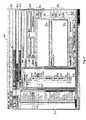
- FIG. 9is a block diagram illustrating an exemplary graphical user interface (GUI) for configuring logging according to one embodiment of the invention.
- GUIgraphical user interface
- the exemplary GUI 900may be included within an administration API, such as administration API 305 of FIG. 3 .
- exemplary GUI 900includes, but is not limited to, a tool bar 901 having one or more buttons or controls, a first window 902 to display one or more configurable items, and a second window 903 to display information associated with one of the items selected from window 902 .
- the items listed in window 902include, among others, a logging configurator 904 .
- the properties associated with item 904may be displayed in window 903 .
- the logging configuration 904may include locations, categories, log destinations, and log formatters as shown at field 905 .
- the log controllers of each locationmay be configured.
- window 906is used to display a list of the locations where the corresponding log controllers may be configured.
- one or more properties of location 908may be displayed and/or configured in window 908 .
- a user or an administratormay configure the severity 909 of the logging, one or more filters in filter window 910 that may be added or removed using buttons 911 , and one or more destinations in destination window 912 that may be added or removed using buttons 913 .
- Other configurationsare also contemplated within the scope of the present invention.
- the exemplary GUI 900is illustrated for illustrations purposes only.
- the functionality and the layout of the GUImay vary.
- the tool bar 901 and/or the page selectors 903may be implemented at different locations of the GUI, such as, for example, at the bottom of the GUI (e.g., near the status bar).
- the number of the buttons or controls associated with the tool bar 901 and the page selectors 905may vary.
- the buttons, the fields, the page selectors, and/or other controlsmay be activated via a variety of manners. For example, those buttons, icons, controls, and page selectors may be activated through one or more keys from a keyboard and/or a pointing device (e.g., a mouse).
- buttons, controls, and/or fieldsmay be activated or deactivated via a pull-down menu or a pop-up menu. It will be appreciated that they can also be activated via other methods apparent to those with ordinary skill in the art, such as, for example, a voice interactive command, a stylus, or a command received over a network, such as a VPN (virtual private network), etc.
- a VPNvirtual private network
- FIG. 10is a block diagram illustrating an exemplary graphical user interface (GUI) 1000 which, in accordance with an embodiment of the invention, may be used by an administrator (e.g., administrator/developer 305 of FIG. 3 ) to configure or modify the logging of an enterprise component being deployed.
- GUIgraphical user interface
- the exemplary GUI 1000may be used by a developer to view (e.g., as a log viewer) or trace (e.g., as a debugger) the deployment or operating information of a deployed enterprise component.
- the exemplary GUI 1000may be integrated within the exemplary GUIs 800 and/or 900 .
- exemplary GUI 1000includes, but is not limited to, a service selection area 1002 , which permits a user to select from a list of services such as, for example, a “log viewer” to view logged information in accordance with the techniques set forth herein.
- a service selection area 1002which permits a user to select from a list of services such as, for example, a “log viewer” to view logged information in accordance with the techniques set forth herein.
- FIG. 12is a block diagram of a data processing system which may be used with one embodiment of the invention.
- the system 1200 shown in FIG. 12may be used as an enterprise computing engine or a client.
- FIG. 12illustrates various components of a computer system, it is not intended to represent any particular architecture or manner of interconnecting the components, as such details are not germane to the present invention. It will also be appreciated that network computers, handheld computers, cell phones, and other data processing systems which have fewer components or perhaps more components may also be used with the present invention.
- the computer system of FIG. 12may, for example, be a J2EE engine or a .NET framework engine.
- the computer system 1200which is a form of a data processing system, includes a bus 1202 which is coupled to a microprocessor 1203 and a ROM 1207 , a volatile RAM 1205 , and a non-volatile memory 1206 .
- the microprocessor 1203which may be a PowerPC microprocessor from Motorola, Inc. or IBM, is coupled to cache memory 1204 as shown in the example of FIG. 12 .
- processor 1203may be a Pentium Processor from Intel Corporation.
- the bus 1202interconnects these various components together and also interconnects these components 1203 , 1207 , 1205 , and 1206 to a display controller and display device 1208 , as well as to input/output (I/O) devices 1210 , which may be mice, keyboards, modems, network interfaces, printers, and other devices which are well-known in the art.
- I/Oinput/output
- the input/output devices 1210are coupled to the system through input/output controllers 1209 .
- the volatile RAM 1205is typically implemented as dynamic RAM (DRAM) which requires power continuously in order to refresh or maintain the data in the memory.
- the non-volatile memory 1206is typically a magnetic hard drive, a magnetic optical drive, an optical drive, or a DVD RAM or other type of memory system which maintains data even after power is removed from the system.
- the non-volatile memorywill also be a random access memory, although this is not required. While FIG.
- the non-volatile memoryis a local device coupled directly to the rest of the components in the data processing system, it will be appreciated that the present invention may utilize a non-volatile memory which is remote from the system, such as a network storage device which is coupled to the data processing system through a network interface such as a modem or Ethernet interface.
- the bus 1202may include one or more buses connected to each other through various bridges, controllers, and/or adapters, as is well-known in the art.
- the I/O controller 1209includes a USB (Universal Serial Bus) adapter for controlling USB peripherals.
- USBUniversal Serial Bus
- a log configuration service(e.g., log configuration service 402 ) may be executed from the memory 1205 to cause processor 1203 to perform logging and tracing configurations illustrated by one or more processes set forth above. Other operations may be performed as well.
- log-filter*⁇ !-- Contains a list of associated destinations. You can have a destination-ref or an anonymous- destination. These two types are displayed further in this document.
- --> ⁇ !ELEMENT associated-destinations((destination-ref
- log-destination((formatter-ref
- ⁇ formatter-ref name‘myFormatter’/>
- the log controlleris an abstraction of a logger that can be used either for tracing (in this case it is called Location and “.” symbol is used as a separator to denote the hierarchical structure) of for logging (then it is called Category and “/” symbol is used as a separator).
- log-controller(minimum-relative-severity*, maximum-relative-severity*, relative-severity*, associated-destinations?, log-filters?)> ⁇ !-- Describes the name of the log controller.
- Two types of log controller namesare available - names for categories and names for locations. Categories are named according to the hierarchical structure known from file systems. You can group together all the categories of log messages concerned with one particular issue under one category. The category name must be separated by “/”. Locations are named according to the hierarchical structure known from Java packages. The category name must be separated by “.”.
Landscapes
- Engineering & Computer Science (AREA)
- Theoretical Computer Science (AREA)
- Computer Hardware Design (AREA)
- Quality & Reliability (AREA)
- Physics & Mathematics (AREA)
- General Engineering & Computer Science (AREA)
- General Physics & Mathematics (AREA)
- Debugging And Monitoring (AREA)
Abstract
Description
- Initial configuration of logging and tracing for server components—each enterprise component can specify in a configuration file (e.g., an XML file), how the logging and tracing has to be configured. For example, according to one embodiment, the configuration file may be packed in the <dispatcher\server>/descriptors folder within the deployable package of the component.
- Mechanisms for runtime management of the logging and tracing configuration—the logging and tracing routines can be configured for a running system using either a graphical user interface or a command line interface (CLI).
- Configuration of logging and tracing for applications that are deployed on the enterprise engine (e.g., J2EE engine)—the log configuration service can extract a logging configuration file, if it is packed in the application deployable file.
| <!-- |
| This is the root element for log configuration. |
| --> |
| <!ELEMENT log-configuration (log-formatters?, log-destinations?, log-controllers?)> |
| <!-- |
| Contains a list of log formatters. |
| --> |
| <!ELEMENT log-formatters (log-formatter*)> |
| <!-- |
| Contains a list of log destinations. |
| --> |
| <!ELEMENT log-destinations (log-destination*)> |
| <!-- |
| Contains a list of log controllers. |
| --> |
| <!ELEMENT log-controllers (log-controller*)> |
| <!-- |
| Contains a list of log filters. |
| --> |
| <!ELEMENT log-filters (log-filter*)> |
| <!-- |
| Contains a list of associated destinations. You can have a destination-ref or an anonymous- |
| destination. These two types are displayed further in this document. |
| --> |
| <!ELEMENT associated-destinations ((destination-ref|anonymous-destination)*)> |
| <!-- |
| Describes a formatter used for formatting log records. |
| --> |
| <!ELEMENT log-formatter EMPTY> |
| <!-- |
| A mandatory attribute that specifies the name of the new formatter. |
| Example: |
| <log-formatters> |
| <log-formatter name=‘myFormatter’ type=‘mypackage.FormatterImpl’ |
| pattern=‘somePattern’/> |
| <log-formatter name=‘anotherFormatter’ type=“mypackage.AnotherFormatterImpl” |
| pattern=‘anotherPattern’/> |
| </log-formatters> |
| --> |
| <!ATTLIST log-formatter name CDATA #REQUIRED> |
| <!-- |
| Defines the type of the formatter. The following default formatter types are available: |
| ListFormetter, TraceFormatter, XMLFormatter. You can also use your own formatter type. |
| --> |
| <!ATTLIST log-formatter type NMTOKEN #REQUIRED> |
| <!-- |
| Configures the formatter with a custom formatting pattern. The pattern allows you to specify |
| the message data fields, with place holders of the form %[[-]<width>[-]]<type>, interspersed |
| with arbitrary text that you want to have included in formatted messages (currently available |
| only for formatters of type TraceFormatter). |
| --> |
| <!ATTLIST log-formatter pattern CDATA #IMPLIED> |
| <!-- |
| Describes a log destination (which is an abstraction of a file, console output, etc.). To a |
| destination you can associate additional or already available formatters and filters. |
| --> |
| <!ELEMENT log-destination ((formatter-ref|anonymous-formatter)?, log-filters?)> |
| <!-- |
| Set the name of the destination. |
| Example: |
| <log-destinations> |
| <log-destination name=‘myDestination0’ type=‘FileLog’ pattern=‘c:\dest0.log’ effective- |
| severity=‘ERROR’ encoding=‘Cp1047’ count=“5” limit=‘800000’> |
| <formatter-ref name=‘myFormatter’/> |
| <log-filters> |
| <log-filter type=‘myPackage.SomeFilter’/> |
| </log-filters> |
| </log-destination> |
| <log-destination name=‘myDestination1’ type=‘ConsoleLog’> |
| <anonymous-formatter type=‘TraceFormatter’/> |
| <log-filters> |
| <log-filter type=‘mypackage.MyLogFilter’/> |
| </log-filters> |
| </log-destination> |
| </log-destinations> |
| --> |
| <!ATTLIST log-destination name ID #REQUIRED> |
| <!-- |
| Sets the destination type. You can either specify your own type, or set a default one: FileLog |
| or ConsoleLog. If you select a ConsoleLog you do not need to specify Pattern, Limit, and |
| Count. |
| --> |
| <!ATTLIST log-destination type NMTOKEN #REQUIRED> |
| <!-- |
| Specifies the path to the file where the logs will be written (applicable only for log |
| destinations of type FileLog). |
| --> |
| <!ATTLIST log-destination pattern CDATA #IMPLIED> |
| <!-- |
| Sets the effective severity of this log. |
| --> |
| <!ATTLIST log-destination effective-severity %severities; #IMPLIED> |
| <!-- |
| Sets the named character encoding to be used for this log. If no character encoding is set the |
| default character encoding is used. |
| --> |
| <!ATTLIST log-destination encoding CDATA #IMPLIED> |
| <!-- |
| Specifies the number of log files for this destination. If it is not specified only one file is used. |
| If a number is specified - when the size of the first file reaches the limit specified in the Limit |
| tag the system starts to write in the second one; this procedure is executed until all the |
| specified files are full, then the system starts to write again in the first file, that is, overwrites |
| the first one. |
| --> |
| <!ATTLIST log-destination count CDATA #IMPLIED> |
| <!-- |
| Specifies the size of the file where the logs will be generated. |
| --> |
| <!ATTLIST log-destination limit CDATA #IMPLIED> |
| <!-- |
| Associates the log destination that is described in the parent tag log-destination with a |
| formatter described in a log-formatter tag. Only one formatter can be associated with a |
| destination. |
| --> |
| <!ELEMENT formatter-ref EMPTY> |
| <!-- |
| The name of the formatter |
| --> |
| <!ATTLIST formatter-ref name CDATA #REQUIRED> |
| <!-- |
| Associates the log destination that is described in the parent tag log-destination with an |
| anonymous formatter (that is a formatter that is not explicitly described with a log-formatter |
| tag). One cannot specify a pattern for an anonymous formatter |
| --> |
| <!ELEMENT anonymous-formatter EMPTY> |
| <!-- |
| Specifies the type of the anonymous formatter. |
| --> |
| <!ATTLIST anonymous-formatter type NMTOKEN #REQUIRED> |
| <!-- |
| Describes a log controller. The log controller is an abstraction of a logger that can be used |
| either for tracing (in this case it is called Location and “.” symbol is used as a separator to |
| denote the hierarchical structure) of for logging (then it is called Category and “/” symbol is |
| used as a separator). |
| --> |
| <!ELEMENT log-controller (minimum-relative-severity*, maximum-relative-severity*, |
| relative-severity*, associated-destinations?, log-filters?)> |
| <!-- |
| Describes the name of the log controller. Two types of log controller names are available - |
| names for categories and names for locations. |
| Categories are named according to the hierarchical structure known from file systems. You |
| can group together all the categories of log messages concerned with one particular issue |
| under one category. The category name must be separated by “/”. |
| Locations are named according to the hierarchical structure known from Java packages. The |
| category name must be separated by “.”. |
| --> |
| <!ATTLIST log-controller name CDATA #REQUIRED> |
| <!-- |
| Sets effective severity to this log controller. |
| --> |
| <!ATTLIST log-controller effective-severity %severities; #IMPLIED> |
| <!-- |
| Sets minimum severity to this log controller. |
| --> |
| <!ATTLIST log-controller minimum-severity %severities; #IMPLIED> |
| <!-- |
| Sets maximum severity to this log controller |
| --> |
| <!ATTLIST log-controller maximum-severity %severities; #IMPLIED> |
| <!-- |
| Assigns a resource bundle name to this log controller. If a resource bundle is assigned, |
| language-independent log messages can be written. |
| --> |
| <!ATTLIST log-controller bundle-name CDATA #IMPLIED> |
| <!-- |
| An optional attribute that specifies whether this log controller will store system critical |
| messages in the database. The default value is “true”. |
| --> |
| <!ATTLIST log-controller db-log %boolean; #IMPLIED> |
| <!-- |
| Sets the minimum severity of this log controller. If its current maximum severity is lower than |
| the argument, the former is set to the argument. If it is a root controller, this method has the |
| same effect as a call to the effective-severity. |
| --> |
| <!ELEMENT minimum-relative-severity EMPTY> |
| <!-- |
| The name of the relative controller. |
| --> |
| <!ATTLIST minimum-relative-severity relative-controller CDATA #REQUIRED> |
| <!-- |
| The value of the minimum relative severity. |
| --> |
| <!ATTLIST minimum-relative-severity value %severities; #REQUIRED> |
| <!-- |
| Sets the maximum severity of this log controller. If its current minimum severity is higher |
| than the argument, the former is set to the argument. If it is a root controller, the method has |
| the same effect as a call to the effective-severity. |
| --> |
| <!ELEMENT maximum-relative-severity EMPTY> |
| <!-- |
| The name of the relative controller. |
| --> |
| <!ATTLIST maximum-relative-severity relative-controller CDATA #REQUIRED> |
| <!-- |
| The value of the maximum relative severity. |
| --> |
| <!ATTLIST maximum-relative-severity value %severities; #REQUIRED> |
| <!-- |
| Sets relative severity to the described log controller. When there is a relative severity set, the |
| effective severity is calculated as the minimum severity of direct severity and severity related |
| to its relative. |
| --> |
| <!ELEMENT relative-severity EMPTY> |
| <!-- |
| The name of the relative controller. |
| --> |
| <!ATTLIST relative-severity relative-controller CDATA #REQUIRED> |
| <!-- |
| The value of the relative severity. |
| --> |
| <!ATTLIST relative-severity value %severities; #REQUIRED> |
| <!-- |
| Describes a filter that, besides the effective severity, controls output via the log controller or |
| log destination. The results of all filters for a given message are logically anded to determine |
| whether a message is to be written to the associated log objects. |
| --> |
| <!ELEMENT log-filter EMPTY> |
| <!-- |
| The type (that is, the full-packaged class name) of the filter. |
| --> |
| <!ATTLIST log-filter type NMTOKEN #REQUIRED> |
| <!-- |
| Associates the log controller that is described in the parent tag log-controller with a formatter |
| described in a log-destination tag. Many destinations can be associated with a log controller. |
| --> |
| <!ELEMENT destination-ref EMPTY> |
| <!-- |
| The name of the associated destination. |
| --> |
| <!ATTLIST destination-ref name IDREF #REQUIRED> |
| <!-- |
| Specifies the type of the association. It can be one of these : PRIVATE_LOG, LOCAL_LOG |
| or LOG |
| --> |
| <!ATTLIST destination-ref association-type %association-types; #REQUIRED> |
| <!-- |
| Associates the log controller that is described in the parent tag log-controller with an |
| anonymous destination (that is a destination that is not explicitly described with a log- |
| destination tag). One cannot specify additional attributes(except type) for an anonymous |
| destination. |
| --> |
| <!ELEMENT anonymous-destination EMPTY> |
| <!-- |
| Sets the destination type. You can either specify your own type, or set a default one: FileLog |
| or ConsoleLog. If you select a ConsoleLog you do not need to specify Pattern, Limit, and |
| Count. |
| --> |
| <!ATTLIST anonymous-destination type NMTOKEN #REQUIRED> |
| <!-- |
| Specifies the type of the association. It can be one of these: PRIVATE_LOG, LOCAL_LOG |
| or LOG |
| --> |
| <!ATTLIST anonymous-destination association-type %association-types; |
| #REQUIRED> |
Claims (19)
Priority Applications (1)
| Application Number | Priority Date | Filing Date | Title |
|---|---|---|---|
| US10/836,851US7743029B2 (en) | 2003-12-30 | 2004-04-30 | Log configuration and online deployment services |
Applications Claiming Priority (3)
| Application Number | Priority Date | Filing Date | Title |
|---|---|---|---|
| US74900503A | 2003-12-30 | 2003-12-30 | |
| US10/749,615US7739374B1 (en) | 2003-12-30 | 2003-12-30 | System and method for configuring tracing and logging functions |
| US10/836,851US7743029B2 (en) | 2003-12-30 | 2004-04-30 | Log configuration and online deployment services |
Related Parent Applications (2)
| Application Number | Title | Priority Date | Filing Date |
|---|---|---|---|
| US10/749,615Continuation-In-PartUS7739374B1 (en) | 2003-12-30 | 2003-12-30 | System and method for configuring tracing and logging functions |
| US74900503AContinuation-In-Part | 2003-12-30 | 2003-12-30 |
Publications (2)
| Publication Number | Publication Date |
|---|---|
| US20050149535A1 US20050149535A1 (en) | 2005-07-07 |
| US7743029B2true US7743029B2 (en) | 2010-06-22 |
Family
ID=34713911
Family Applications (1)
| Application Number | Title | Priority Date | Filing Date |
|---|---|---|---|
| US10/836,851Active2027-07-14US7743029B2 (en) | 2003-12-30 | 2004-04-30 | Log configuration and online deployment services |
Country Status (1)
| Country | Link |
|---|---|
| US (1) | US7743029B2 (en) |
Cited By (12)
| Publication number | Priority date | Publication date | Assignee | Title |
|---|---|---|---|---|
| US20100023545A1 (en)* | 2008-07-25 | 2010-01-28 | Tibbo Technology, Inc. | Data logging system and method thereof for heterogeneous data |
| US20100211826A1 (en)* | 2005-11-12 | 2010-08-19 | Logrhythm, Inc. | Log collection, structuring and processing |
| US8543694B2 (en) | 2010-11-24 | 2013-09-24 | Logrhythm, Inc. | Scalable analytical processing of structured data |
| US9116906B2 (en)* | 2012-06-12 | 2015-08-25 | Sap Se | Centralized read access logging |
| US9262248B2 (en) | 2012-07-06 | 2016-02-16 | International Business Machines Corporation | Log configuration of distributed applications |
| US9384112B2 (en) | 2010-07-01 | 2016-07-05 | Logrhythm, Inc. | Log collection, structuring and processing |
| US9459990B2 (en) | 2012-03-27 | 2016-10-04 | International Business Machines Corporation | Automatic and transparent application logging |
| US9652743B2 (en) | 2012-05-30 | 2017-05-16 | Sap Se | Brainstorming in a cloud environment |
| US9780995B2 (en) | 2010-11-24 | 2017-10-03 | Logrhythm, Inc. | Advanced intelligence engine |
| US9807154B2 (en) | 2014-09-26 | 2017-10-31 | Lenovo Enterprise Solutions (Singapore) Pte, Ltd. | Scalable logging control for distributed network devices |
| US10540331B2 (en) | 2016-11-29 | 2020-01-21 | Sap Se | Hierarchically stored data processing |
| CN111680010A (en)* | 2020-08-14 | 2020-09-18 | 北京东方通软件有限公司 | Design Method of Logging System for JavaEE Application Server |
Families Citing this family (76)
| Publication number | Priority date | Publication date | Assignee | Title |
|---|---|---|---|---|
| US7707189B2 (en)* | 2004-10-05 | 2010-04-27 | Microsoft Corporation | Log management system and method |
| US8255876B2 (en)* | 2006-07-28 | 2012-08-28 | Apple Inc. | Execution difference identification tool |
| US8949933B2 (en)* | 2006-08-15 | 2015-02-03 | International Business Machines Corporation | Centralized management of technical records across an enterprise |
| US9753747B2 (en)* | 2006-11-16 | 2017-09-05 | Oracle International Corporation | Dynamic generated web UI for configuration |
| US20090063395A1 (en)* | 2007-08-30 | 2009-03-05 | International Business Machines Corporation | Mapping log sets between different log analysis tools in a problem determination environment |
| US7493598B1 (en)* | 2008-01-26 | 2009-02-17 | International Business Machines Corporation | Method and system for variable trace entry decay |
| CN103412745B (en)* | 2013-07-18 | 2016-08-24 | 中国联合网络通信集团有限公司 | A kind of exploitation and application platform |
| US9086934B2 (en)* | 2013-08-27 | 2015-07-21 | International Business Machines Corporation | Selecting output destinations for kernel messages |
| US9715402B2 (en) | 2014-09-30 | 2017-07-25 | Amazon Technologies, Inc. | Dynamic code deployment and versioning |
| US10048974B1 (en) | 2014-09-30 | 2018-08-14 | Amazon Technologies, Inc. | Message-based computation request scheduling |
| US9600312B2 (en) | 2014-09-30 | 2017-03-21 | Amazon Technologies, Inc. | Threading as a service |
| US9678773B1 (en) | 2014-09-30 | 2017-06-13 | Amazon Technologies, Inc. | Low latency computational capacity provisioning |
| US9323556B2 (en) | 2014-09-30 | 2016-04-26 | Amazon Technologies, Inc. | Programmatic event detection and message generation for requests to execute program code |
| US9146764B1 (en) | 2014-09-30 | 2015-09-29 | Amazon Technologies, Inc. | Processing event messages for user requests to execute program code |
| US9830193B1 (en) | 2014-09-30 | 2017-11-28 | Amazon Technologies, Inc. | Automatic management of low latency computational capacity |
| US9413626B2 (en) | 2014-12-05 | 2016-08-09 | Amazon Technologies, Inc. | Automatic management of resource sizing |
| US9588790B1 (en) | 2015-02-04 | 2017-03-07 | Amazon Technologies, Inc. | Stateful virtual compute system |
| US9733967B2 (en) | 2015-02-04 | 2017-08-15 | Amazon Technologies, Inc. | Security protocols for low latency execution of program code |
| US9930103B2 (en) | 2015-04-08 | 2018-03-27 | Amazon Technologies, Inc. | Endpoint management system providing an application programming interface proxy service |
| US9785476B2 (en) | 2015-04-08 | 2017-10-10 | Amazon Technologies, Inc. | Endpoint management system and virtual compute system |
| US9910713B2 (en) | 2015-12-21 | 2018-03-06 | Amazon Technologies, Inc. | Code execution request routing |
| US10067801B1 (en) | 2015-12-21 | 2018-09-04 | Amazon Technologies, Inc. | Acquisition and maintenance of compute capacity |
| US10891145B2 (en) | 2016-03-30 | 2021-01-12 | Amazon Technologies, Inc. | Processing pre-existing data sets at an on demand code execution environment |
| US11132213B1 (en) | 2016-03-30 | 2021-09-28 | Amazon Technologies, Inc. | Dependency-based process of pre-existing data sets at an on demand code execution environment |
| US10503623B2 (en)* | 2016-04-29 | 2019-12-10 | Ca, Inc. | Monitoring containerized applications |
| US10102040B2 (en) | 2016-06-29 | 2018-10-16 | Amazon Technologies, Inc | Adjusting variable limit on concurrent code executions |
| US10884787B1 (en) | 2016-09-23 | 2021-01-05 | Amazon Technologies, Inc. | Execution guarantees in an on-demand network code execution system |
| US10810099B2 (en)* | 2017-09-11 | 2020-10-20 | Internatinal Business Machines Corporation | Cognitive in-memory API logging |
| US10564946B1 (en) | 2017-12-13 | 2020-02-18 | Amazon Technologies, Inc. | Dependency handling in an on-demand network code execution system |
| US10733085B1 (en) | 2018-02-05 | 2020-08-04 | Amazon Technologies, Inc. | Detecting impedance mismatches due to cross-service calls |
| US10831898B1 (en) | 2018-02-05 | 2020-11-10 | Amazon Technologies, Inc. | Detecting privilege escalations in code including cross-service calls |
| US10725752B1 (en) | 2018-02-13 | 2020-07-28 | Amazon Technologies, Inc. | Dependency handling in an on-demand network code execution system |
| US10776091B1 (en)* | 2018-02-26 | 2020-09-15 | Amazon Technologies, Inc. | Logging endpoint in an on-demand code execution system |
| US10853115B2 (en) | 2018-06-25 | 2020-12-01 | Amazon Technologies, Inc. | Execution of auxiliary functions in an on-demand network code execution system |
| US10649749B1 (en) | 2018-06-26 | 2020-05-12 | Amazon Technologies, Inc. | Cross-environment application of tracing information for improved code execution |
| US11146569B1 (en) | 2018-06-28 | 2021-10-12 | Amazon Technologies, Inc. | Escalation-resistant secure network services using request-scoped authentication information |
| US10949237B2 (en) | 2018-06-29 | 2021-03-16 | Amazon Technologies, Inc. | Operating system customization in an on-demand network code execution system |
| CN110730086B (en)* | 2018-07-16 | 2022-11-25 | 视联动力信息技术股份有限公司 | Method and device for outputting log information |
| US11099870B1 (en) | 2018-07-25 | 2021-08-24 | Amazon Technologies, Inc. | Reducing execution times in an on-demand network code execution system using saved machine states |
| US11099917B2 (en) | 2018-09-27 | 2021-08-24 | Amazon Technologies, Inc. | Efficient state maintenance for execution environments in an on-demand code execution system |
| US11243953B2 (en) | 2018-09-27 | 2022-02-08 | Amazon Technologies, Inc. | Mapreduce implementation in an on-demand network code execution system and stream data processing system |
| US11943093B1 (en) | 2018-11-20 | 2024-03-26 | Amazon Technologies, Inc. | Network connection recovery after virtual machine transition in an on-demand network code execution system |
| US10884812B2 (en) | 2018-12-13 | 2021-01-05 | Amazon Technologies, Inc. | Performance-based hardware emulation in an on-demand network code execution system |
| US11010188B1 (en) | 2019-02-05 | 2021-05-18 | Amazon Technologies, Inc. | Simulated data object storage using on-demand computation of data objects |
| US11861386B1 (en) | 2019-03-22 | 2024-01-02 | Amazon Technologies, Inc. | Application gateways in an on-demand network code execution system |
| US12327133B1 (en) | 2019-03-22 | 2025-06-10 | Amazon Technologies, Inc. | Application gateways in an on-demand network code execution system |
| US11119809B1 (en) | 2019-06-20 | 2021-09-14 | Amazon Technologies, Inc. | Virtualization-based transaction handling in an on-demand network code execution system |
| US11159528B2 (en) | 2019-06-28 | 2021-10-26 | Amazon Technologies, Inc. | Authentication to network-services using hosted authentication information |
| US11190609B2 (en) | 2019-06-28 | 2021-11-30 | Amazon Technologies, Inc. | Connection pooling for scalable network services |
| US11115404B2 (en) | 2019-06-28 | 2021-09-07 | Amazon Technologies, Inc. | Facilitating service connections in serverless code executions |
| US11055112B2 (en) | 2019-09-27 | 2021-07-06 | Amazon Technologies, Inc. | Inserting executions of owner-specified code into input/output path of object storage service |
| US11023311B2 (en) | 2019-09-27 | 2021-06-01 | Amazon Technologies, Inc. | On-demand code execution in input path of data uploaded to storage service in multiple data portions |
| US11656892B1 (en) | 2019-09-27 | 2023-05-23 | Amazon Technologies, Inc. | Sequential execution of user-submitted code and native functions |
| US10908927B1 (en) | 2019-09-27 | 2021-02-02 | Amazon Technologies, Inc. | On-demand execution of object filter code in output path of object storage service |
| US11360948B2 (en) | 2019-09-27 | 2022-06-14 | Amazon Technologies, Inc. | Inserting owner-specified data processing pipelines into input/output path of object storage service |
| US11416628B2 (en) | 2019-09-27 | 2022-08-16 | Amazon Technologies, Inc. | User-specific data manipulation system for object storage service based on user-submitted code |
| US11263220B2 (en) | 2019-09-27 | 2022-03-01 | Amazon Technologies, Inc. | On-demand execution of object transformation code in output path of object storage service |
| US11394761B1 (en) | 2019-09-27 | 2022-07-19 | Amazon Technologies, Inc. | Execution of user-submitted code on a stream of data |
| US11023416B2 (en) | 2019-09-27 | 2021-06-01 | Amazon Technologies, Inc. | Data access control system for object storage service based on owner-defined code |
| US11386230B2 (en) | 2019-09-27 | 2022-07-12 | Amazon Technologies, Inc. | On-demand code obfuscation of data in input path of object storage service |
| US11250007B1 (en) | 2019-09-27 | 2022-02-15 | Amazon Technologies, Inc. | On-demand execution of object combination code in output path of object storage service |
| US11550944B2 (en) | 2019-09-27 | 2023-01-10 | Amazon Technologies, Inc. | Code execution environment customization system for object storage service |
| US11106477B2 (en) | 2019-09-27 | 2021-08-31 | Amazon Technologies, Inc. | Execution of owner-specified code during input/output path to object storage service |
| US10996961B2 (en) | 2019-09-27 | 2021-05-04 | Amazon Technologies, Inc. | On-demand indexing of data in input path of object storage service |
| US11580255B2 (en)* | 2019-11-11 | 2023-02-14 | Bank Of America Corporation | Security tool for n-tier platforms |
| US10942795B1 (en) | 2019-11-27 | 2021-03-09 | Amazon Technologies, Inc. | Serverless call distribution to utilize reserved capacity without inhibiting scaling |
| US11119826B2 (en) | 2019-11-27 | 2021-09-14 | Amazon Technologies, Inc. | Serverless call distribution to implement spillover while avoiding cold starts |
| US11714682B1 (en) | 2020-03-03 | 2023-08-01 | Amazon Technologies, Inc. | Reclaiming computing resources in an on-demand code execution system |
| US11188391B1 (en) | 2020-03-11 | 2021-11-30 | Amazon Technologies, Inc. | Allocating resources to on-demand code executions under scarcity conditions |
| US11775640B1 (en) | 2020-03-30 | 2023-10-03 | Amazon Technologies, Inc. | Resource utilization-based malicious task detection in an on-demand code execution system |
| US11593270B1 (en) | 2020-11-25 | 2023-02-28 | Amazon Technologies, Inc. | Fast distributed caching using erasure coded object parts |
| US11550713B1 (en) | 2020-11-25 | 2023-01-10 | Amazon Technologies, Inc. | Garbage collection in distributed systems using life cycled storage roots |
| US11388210B1 (en) | 2021-06-30 | 2022-07-12 | Amazon Technologies, Inc. | Streaming analytics using a serverless compute system |
| US11968280B1 (en) | 2021-11-24 | 2024-04-23 | Amazon Technologies, Inc. | Controlling ingestion of streaming data to serverless function executions |
| US12015603B2 (en) | 2021-12-10 | 2024-06-18 | Amazon Technologies, Inc. | Multi-tenant mode for serverless code execution |
| US12381878B1 (en) | 2023-06-27 | 2025-08-05 | Amazon Technologies, Inc. | Architecture for selective use of private paths between cloud services |
Citations (28)
| Publication number | Priority date | Publication date | Assignee | Title |
|---|---|---|---|---|
| US5577252A (en) | 1993-07-28 | 1996-11-19 | Sun Microsystems, Inc. | Methods and apparatus for implementing secure name servers in an object-oriented system |
| US5608720A (en) | 1993-03-09 | 1997-03-04 | Hubbell Incorporated | Control system and operations system interface for a network element in an access system |
| US5706501A (en) | 1995-02-23 | 1998-01-06 | Fuji Xerox Co., Ltd. | Apparatus and method for managing resources in a network combining operations with name resolution functions |
| US5745683A (en) | 1995-07-05 | 1998-04-28 | Sun Microsystems, Inc. | System and method for allowing disparate naming service providers to dynamically join a naming federation |
| US6083281A (en)* | 1997-11-14 | 2000-07-04 | Nortel Networks Corporation | Process and apparatus for tracing software entities in a distributed system |
| US6144967A (en)* | 1996-01-25 | 2000-11-07 | International Business Machines Corporation | Object oriented processing log analysis tool framework mechanism |
| US6154777A (en) | 1996-07-01 | 2000-11-28 | Sun Microsystems, Inc. | System for context-dependent name resolution |
| US6466570B1 (en) | 1995-12-11 | 2002-10-15 | Hewlett-Packard Company | Method of accessing service resource items that are for use in a telecommunications system |
| US20030005173A1 (en) | 2001-06-29 | 2003-01-02 | International Business Machines Corporation | Methods and apparatus in distributed remote logging system for remote adhoc data analysis customized with multilevel hierarchical logger tree |
| US6539501B1 (en) | 1999-12-16 | 2003-03-25 | International Business Machines Corporation | Method, system, and program for logging statements to monitor execution of a program |
| US6553384B1 (en) | 1999-06-14 | 2003-04-22 | International Business Machines Corporation | Transactional name service |
| US20030120593A1 (en)* | 2001-08-15 | 2003-06-26 | Visa U.S.A. | Method and system for delivering multiple services electronically to customers via a centralized portal architecture |
| US20030195870A1 (en) | 2002-04-15 | 2003-10-16 | International Business Machines Corporation | System and method for performing lookups across namespace domains using universal resource locators |
| US20040028059A1 (en) | 2002-06-04 | 2004-02-12 | Ravi Josyula | Efficient redirection of logging and tracing information in network node with distributed architecture |
| US6721747B2 (en) | 2000-01-14 | 2004-04-13 | Saba Software, Inc. | Method and apparatus for an information server |
| US6751646B1 (en) | 2000-06-01 | 2004-06-15 | Sprint Communications Company L.P. | Method and apparatus for implementing CORBA compliant name services incorporating load balancing features |
| US6802067B1 (en)* | 2000-10-27 | 2004-10-05 | Sprint Communications Company, L.P. | Computer software framework and method for logging messages |
| US20040220926A1 (en) | 2000-01-03 | 2004-11-04 | Interactual Technologies, Inc., A California Cpr[P | Personalization services for entities from multiple sources |
| US20040237093A1 (en) | 2003-03-28 | 2004-11-25 | International Business Machines Corporation | Technique to generically manage extensible correlation data |
| US6834284B2 (en) | 1999-08-12 | 2004-12-21 | International Business Machines Corporation | Process and system for providing name service scoping behavior in java object-oriented environment |
| US6850893B2 (en) | 2000-01-14 | 2005-02-01 | Saba Software, Inc. | Method and apparatus for an improved security system mechanism in a business applications management system platform |
| US6985848B2 (en) | 2000-03-02 | 2006-01-10 | Texas Instruments Incorporated | Obtaining and exporting on-chip data processor trace and timing information |
| US7058639B1 (en) | 2002-04-08 | 2006-06-06 | Oracle International Corporation | Use of dynamic multi-level hash table for managing hierarchically structured information |
| US7120685B2 (en) | 2001-06-26 | 2006-10-10 | International Business Machines Corporation | Method and apparatus for dynamic configurable logging of activities in a distributed computing system |
| US7174370B1 (en) | 2001-04-17 | 2007-02-06 | Atul Saini | System and methodology for developing, integrating and monitoring computer applications and programs |
| US7240334B1 (en) | 2000-06-29 | 2007-07-03 | International Business Machines Corporation | Methods, systems, and computer program products for deferred computer program tracing |
| US7251809B2 (en) | 2002-04-12 | 2007-07-31 | International Business Machines Corporation | Dynamic generation of program execution trace files in a standard markup language |
| US7308475B1 (en) | 2003-05-06 | 2007-12-11 | F5 Networks, Inc. | Method and system for accessing network services |
- 2004
- 2004-04-30USUS10/836,851patent/US7743029B2/enactiveActive
Patent Citations (29)
| Publication number | Priority date | Publication date | Assignee | Title |
|---|---|---|---|---|
| US5608720A (en) | 1993-03-09 | 1997-03-04 | Hubbell Incorporated | Control system and operations system interface for a network element in an access system |
| US5577252A (en) | 1993-07-28 | 1996-11-19 | Sun Microsystems, Inc. | Methods and apparatus for implementing secure name servers in an object-oriented system |
| US5706501A (en) | 1995-02-23 | 1998-01-06 | Fuji Xerox Co., Ltd. | Apparatus and method for managing resources in a network combining operations with name resolution functions |
| US5745683A (en) | 1995-07-05 | 1998-04-28 | Sun Microsystems, Inc. | System and method for allowing disparate naming service providers to dynamically join a naming federation |
| US6466570B1 (en) | 1995-12-11 | 2002-10-15 | Hewlett-Packard Company | Method of accessing service resource items that are for use in a telecommunications system |
| US6144967A (en)* | 1996-01-25 | 2000-11-07 | International Business Machines Corporation | Object oriented processing log analysis tool framework mechanism |
| US6154777A (en) | 1996-07-01 | 2000-11-28 | Sun Microsystems, Inc. | System for context-dependent name resolution |
| US6083281A (en)* | 1997-11-14 | 2000-07-04 | Nortel Networks Corporation | Process and apparatus for tracing software entities in a distributed system |
| US6553384B1 (en) | 1999-06-14 | 2003-04-22 | International Business Machines Corporation | Transactional name service |
| US6834284B2 (en) | 1999-08-12 | 2004-12-21 | International Business Machines Corporation | Process and system for providing name service scoping behavior in java object-oriented environment |
| US6539501B1 (en) | 1999-12-16 | 2003-03-25 | International Business Machines Corporation | Method, system, and program for logging statements to monitor execution of a program |
| US20040220926A1 (en) | 2000-01-03 | 2004-11-04 | Interactual Technologies, Inc., A California Cpr[P | Personalization services for entities from multiple sources |
| US6721747B2 (en) | 2000-01-14 | 2004-04-13 | Saba Software, Inc. | Method and apparatus for an information server |
| US6850893B2 (en) | 2000-01-14 | 2005-02-01 | Saba Software, Inc. | Method and apparatus for an improved security system mechanism in a business applications management system platform |
| US6985848B2 (en) | 2000-03-02 | 2006-01-10 | Texas Instruments Incorporated | Obtaining and exporting on-chip data processor trace and timing information |
| US6751646B1 (en) | 2000-06-01 | 2004-06-15 | Sprint Communications Company L.P. | Method and apparatus for implementing CORBA compliant name services incorporating load balancing features |
| US7240334B1 (en) | 2000-06-29 | 2007-07-03 | International Business Machines Corporation | Methods, systems, and computer program products for deferred computer program tracing |
| US6802067B1 (en)* | 2000-10-27 | 2004-10-05 | Sprint Communications Company, L.P. | Computer software framework and method for logging messages |
| US7174370B1 (en) | 2001-04-17 | 2007-02-06 | Atul Saini | System and methodology for developing, integrating and monitoring computer applications and programs |
| US7120685B2 (en) | 2001-06-26 | 2006-10-10 | International Business Machines Corporation | Method and apparatus for dynamic configurable logging of activities in a distributed computing system |
| US6871228B2 (en)* | 2001-06-29 | 2005-03-22 | International Business Machines Corporation | Methods and apparatus in distributed remote logging system for remote adhoc data analysis customized with multilevel hierarchical logger tree |
| US20030005173A1 (en) | 2001-06-29 | 2003-01-02 | International Business Machines Corporation | Methods and apparatus in distributed remote logging system for remote adhoc data analysis customized with multilevel hierarchical logger tree |
| US20030120593A1 (en)* | 2001-08-15 | 2003-06-26 | Visa U.S.A. | Method and system for delivering multiple services electronically to customers via a centralized portal architecture |
| US7058639B1 (en) | 2002-04-08 | 2006-06-06 | Oracle International Corporation | Use of dynamic multi-level hash table for managing hierarchically structured information |
| US7251809B2 (en) | 2002-04-12 | 2007-07-31 | International Business Machines Corporation | Dynamic generation of program execution trace files in a standard markup language |
| US20030195870A1 (en) | 2002-04-15 | 2003-10-16 | International Business Machines Corporation | System and method for performing lookups across namespace domains using universal resource locators |
| US20040028059A1 (en) | 2002-06-04 | 2004-02-12 | Ravi Josyula | Efficient redirection of logging and tracing information in network node with distributed architecture |
| US20040237093A1 (en) | 2003-03-28 | 2004-11-25 | International Business Machines Corporation | Technique to generically manage extensible correlation data |
| US7308475B1 (en) | 2003-05-06 | 2007-12-11 | F5 Networks, Inc. | Method and system for accessing network services |
Non-Patent Citations (35)
| Title |
|---|
| "JNDI SPI: Java Naming and Directory Service Provider Interface", SUN Microsystems, Inc.,JNDI SPI: Java Naming and Directory Service Provider Interface, Java Naming and Directory SPI, Jan. 29, 1998, pp. ii-43, ii-43. |
| "JNDI: Java Naming and Directory Interface", SUN Microsystems, Inc.,JNDI: Java Naming and Directory Interface, Java Naming and Directory, Jan. 29, 1998, pp. ii-63, Palo Alto, California., ii-63. |
| "Log file logging levels", Retrieved form internet archive on Jul. 1, 2009 at: http://web.archive.org/web/20030814011949/http:www.faqs.org/docs/evms/loglevels.html. (Aug. 14, 2003). |
| Final Office Action for U.S. Appl. No. 10/749,005, Mailed Aug. 3, 2009, 10 pages. |
| Final Office Action for U.S. Appl. No. 10/749,615, Mailed Jul. 7, 2009, 28 pages. |
| Final Office Action mailed Aug. 10, 2007, for U.S. Appl. No. 10/749,005, filed Dec. 30, 2003. 8 pages. |
| Final Office Action mailed Jun. 11, 2008, for U.S. Appl. No. 10/749,005, filed Dec. 30, 2003. 13 pages. |
| Lee, Rosanna , "The JNDI Tutorial, Building Directory-Enabled Java Applications", published online by Sun, revised Nov. 1, 2002, pp. 1-300. |
| Lee, Rosanna , "The JNDI Tutorial, Building Directory-Enabled Java Applications", published online by Sun, revised Nov. 1, 2002, pp. 301-600. |
| Lee, Rosanna , "The JNDI Tutorial, Building Directory-Enabled Java Applications", published online by Sun, revised Nov. 1, 2002, pp. 601-900. |
| Lee, Rosanna , "The JNDI Tutorial, Building Directory-Enabled Java Applications", published online by Sun, revised Nov. 1, 2002, pp. 901-1170. |
| Mockapetris, P , ""Domain Name-Implementation Specification"", P. Mockapetris, RFC 1035, "Domain Name-Impelemntation and Specification", Nov. 1987, IETF, p. 1-56, p-156. |
| Non-Final Office Action dated Oct. 16, 2008, U.S. Appl. No. 10/856,051, filed May 27, 2004, whole document. |
| Non-Final Office Action for U.S. Appl. No. 10/749,005, Mailed Feb. 3, 2009, 16 pages. |
| Non-Final Office Action for U.S. Appl. No. 10/749,615 Mailed Jan. 17, 2008, 17 pages. |
| Non-Final Office Action for U.S. Appl. No. 10/749,615, Mailed Dec. 23, 2008, 27 pages. |
| Non-Final Office Action for U.S. Appl. No. 10/856,051, Mailed Apr. 13, 2009, 15 pages. |
| Notice of Allowance and Fees for U.S. Appl. No. 10/749,615, Mailed Jan. 29, 2010. 11 Pages. |
| Office Action mailed Feb. 26, 2007, for U.S. Appl. No. 10/749,005, filed Dec. 30, 2003. 10 pages. |
| Office Action mailed Jan. 4, 2008, for U.S. Appl. No. 10/749,005, filed Dec. 30, 2003. 10 pages. |
| Perrone, et al., ""Build Java System with J2EE"", Perrone et al., "Build Java System with J2EE", chapter 19, Naming Services Jun. 2000 published by Sams, pp. 1-27, pp. 1-27. |
| Petev, Petio , et al., Final Office Action, dated Nov. 15, 2007, U.S. Appl. No. 10/856,053, filed May 27, 2004, 15 pgs. |
| Petev, Petio , et al., Non-Final Office Action, dated Dec. 5, 2006, U.S. Appl. No. 10/856,053, filed May 27, 2004, 15 pgs. |
| Petev, Petio , et al., Non-Final Office Action, dated Jan. 24, 2008, U.S. Appl. No. 10/856,051, filed May 27, 2004, 15 pgs. |
| Petev, Petio , et al., Non-Final Office Action, dated May 31, 2007, U.S. Appl. No. 10/856,053, filed May 27, 2004, 16 pgs. |
| Petev, Petio , Non-Final Office Action, dated Aug. 10, 2007, U.S. Appl. No. 10/856,051, filed May 27, 2004, 17 pgs. |
| Preferences", pp. 1-24, copyright 2003", . |
| Preferences", pp. 1-24, copyright 2003", <http://java.sun.com/j2se/1.4.2/docs/api/java/util/prefs/package-summary.html>. |
| USPTO, "FOA Mailed Aug. 19, 2008 for U.S. Appl. No. 10/749,086", Whole Document. |
| USPTO, "FOA Mailed Aug. 28, 2008 for U.S. Appl. No. 10/813,999", Whole Document. |
| USPTO, "FOA Mailed Sep. 26, 2007 for U.S. Appl. No. 10/749,086", Whole Document. |
| USPTO, "OA Mailed Feb. 29, 2008 for U.S. Appl. No. 10/749,086", Whole Document. |
| USPTO, "OA Mailed Feb. 4, 2009 for U.S. Appl. No. 10/749,086", Whole Document. |
| USPTO, "OA Mailed May 31, 2007 for U.S. Appl. No. 10/749,086", Whole Document. |
| USPTO, "Office Action", U.S. Appl. No. 10/748,779, mailed Sep. 26, 2008, 16 pages. |
Cited By (19)
| Publication number | Priority date | Publication date | Assignee | Title |
|---|---|---|---|---|
| US20100211826A1 (en)* | 2005-11-12 | 2010-08-19 | Logrhythm, Inc. | Log collection, structuring and processing |
| US8032489B2 (en)* | 2005-11-12 | 2011-10-04 | LogRhythm Inc. | Log collection, structuring and processing |
| US8024297B2 (en)* | 2008-07-25 | 2011-09-20 | Tibbo Technology, Inc. | Data logging system and method thereof for heterogeneous data |
| US20100023545A1 (en)* | 2008-07-25 | 2010-01-28 | Tibbo Technology, Inc. | Data logging system and method thereof for heterogeneous data |
| US10122575B2 (en) | 2010-07-01 | 2018-11-06 | LogRhythm Inc. | Log collection, structuring and processing |
| US9384112B2 (en) | 2010-07-01 | 2016-07-05 | Logrhythm, Inc. | Log collection, structuring and processing |
| US8543694B2 (en) | 2010-11-24 | 2013-09-24 | Logrhythm, Inc. | Scalable analytical processing of structured data |
| US12106229B2 (en) | 2010-11-24 | 2024-10-01 | Logrhythm, Inc. | Advanced intelligence engine for identifying an event of interest |
| US11361230B2 (en) | 2010-11-24 | 2022-06-14 | LogRhythm Inc. | Advanced intelligence engine |
| US9576243B2 (en) | 2010-11-24 | 2017-02-21 | Logrhythm, Inc. | Advanced intelligence engine |
| US10268957B2 (en) | 2010-11-24 | 2019-04-23 | Logrhythm, Inc. | Advanced intelligence engine |
| US9780995B2 (en) | 2010-11-24 | 2017-10-03 | Logrhythm, Inc. | Advanced intelligence engine |
| US9459990B2 (en) | 2012-03-27 | 2016-10-04 | International Business Machines Corporation | Automatic and transparent application logging |
| US9652743B2 (en) | 2012-05-30 | 2017-05-16 | Sap Se | Brainstorming in a cloud environment |
| US9116906B2 (en)* | 2012-06-12 | 2015-08-25 | Sap Se | Centralized read access logging |
| US9262248B2 (en) | 2012-07-06 | 2016-02-16 | International Business Machines Corporation | Log configuration of distributed applications |
| US9807154B2 (en) | 2014-09-26 | 2017-10-31 | Lenovo Enterprise Solutions (Singapore) Pte, Ltd. | Scalable logging control for distributed network devices |
| US10540331B2 (en) | 2016-11-29 | 2020-01-21 | Sap Se | Hierarchically stored data processing |
| CN111680010A (en)* | 2020-08-14 | 2020-09-18 | 北京东方通软件有限公司 | Design Method of Logging System for JavaEE Application Server |
Also Published As
| Publication number | Publication date |
|---|---|
| US20050149535A1 (en) | 2005-07-07 |
Similar Documents
| Publication | Publication Date | Title |
|---|---|---|
| US7743029B2 (en) | Log configuration and online deployment services | |
| JP3590688B2 (en) | Method and system for constructing an installation plan object for installing an application | |
| US7526550B2 (en) | Unified logging service with a log viewer | |
| US6618735B1 (en) | System and method for protecting shared system files | |
| RU2419854C2 (en) | Template based service management | |
| KR100373920B1 (en) | System and method for role based dynamic configuration of user profiles | |
| US7366955B2 (en) | Automated test execution framework with central management | |
| US7606893B2 (en) | System and method for integrated logging and tracing functions in an enterprise network | |
| US7721266B2 (en) | Unified logging service with a logging formatter | |
| US7526734B2 (en) | User interfaces for developing enterprise applications | |
| US6772031B1 (en) | Method of, system for, and computer program product for providing a job monitor | |
| US8271469B2 (en) | Method and system for a non-hierarchical trace system using a hierarchical control interface | |
| US20080163092A1 (en) | One stop install, un-install, and update of software products | |
| US10481878B2 (en) | User interface apparatus and methods | |
| US9442822B2 (en) | Providing a visual representation of a sub-set of a visual program | |
| JP2009510563A (en) | Method and system for managing and organizing installation of software packages | |
| JP7040800B2 (en) | Architecture, methods and equipment for collecting and displaying computer file metadata | |
| US8365165B2 (en) | Dynamic addition of products and removal of software products on a distribution server | |
| US6966052B1 (en) | Method and apparatus for top-down testing based on end user documentation | |
| US7007273B2 (en) | Object oriented model of preloading software | |
| WO2024164630A1 (en) | Microkernel operating system based security monitoring method, apparatus, device, and chip | |
| Cisco | Release Notes for Cisco Element Management Framework v3.1 | |
| RU2316043C2 (en) | Mechanism and method for representing event information in access system | |
| KR101088166B1 (en) | A computer-executable recording medium having recorded thereon software for specifying a user interface program | |
| Beckner et al. | Administration and Operations |
Legal Events
| Date | Code | Title | Description |
|---|---|---|---|
| AS | Assignment | Owner name:SAP AKTIENGESELLSCHAFT, GERMANY Free format text:ASSIGNMENT OF ASSIGNORS INTEREST;ASSIGNORS:FREY, GREGOR K.;PETROV, MIROSLAV R.;MANEFF, GEORGI G.;REEL/FRAME:015934/0337;SIGNING DATES FROM 20040723 TO 20041014 Owner name:SAP AKTIENGESELLSCHAFT,GERMANY Free format text:ASSIGNMENT OF ASSIGNORS INTEREST;ASSIGNORS:FREY, GREGOR K.;PETROV, MIROSLAV R.;MANEFF, GEORGI G.;SIGNING DATES FROM 20040723 TO 20041014;REEL/FRAME:015934/0337 | |
| FEPP | Fee payment procedure | Free format text:PAYOR NUMBER ASSIGNED (ORIGINAL EVENT CODE: ASPN); ENTITY STATUS OF PATENT OWNER: LARGE ENTITY | |
| FEPP | Fee payment procedure | Free format text:PAYOR NUMBER ASSIGNED (ORIGINAL EVENT CODE: ASPN); ENTITY STATUS OF PATENT OWNER: LARGE ENTITY Free format text:PAYER NUMBER DE-ASSIGNED (ORIGINAL EVENT CODE: RMPN); ENTITY STATUS OF PATENT OWNER: LARGE ENTITY | |
| STCF | Information on status: patent grant | Free format text:PATENTED CASE | |
| FPAY | Fee payment | Year of fee payment:4 | |
| AS | Assignment | Owner name:SAP SE, GERMANY Free format text:CHANGE OF NAME;ASSIGNOR:SAP AG;REEL/FRAME:033625/0334 Effective date:20140707 | |
| MAFP | Maintenance fee payment | Free format text:PAYMENT OF MAINTENANCE FEE, 8TH YEAR, LARGE ENTITY (ORIGINAL EVENT CODE: M1552) Year of fee payment:8 | |
| MAFP | Maintenance fee payment | Free format text:PAYMENT OF MAINTENANCE FEE, 12TH YEAR, LARGE ENTITY (ORIGINAL EVENT CODE: M1553); ENTITY STATUS OF PATENT OWNER: LARGE ENTITY Year of fee payment:12 |