US7742670B2 - Index-matching gel for nanostructure optical fibers and mechanical splice assembly and connector using same - Google Patents
Index-matching gel for nanostructure optical fibers and mechanical splice assembly and connector using sameDownload PDFInfo
- Publication number
- US7742670B2 US7742670B2US12/221,040US22104008AUS7742670B2US 7742670 B2US7742670 B2US 7742670B2US 22104008 AUS22104008 AUS 22104008AUS 7742670 B2US7742670 B2US 7742670B2
- Authority
- US
- United States
- Prior art keywords
- fiber
- index
- optical fiber
- nanostructure
- gel
- Prior art date
- Legal status (The legal status is an assumption and is not a legal conclusion. Google has not performed a legal analysis and makes no representation as to the accuracy of the status listed.)
- Expired - Fee Related, expires
Links
- 0C.C.C.C.[1*][Si]([2*])(C)O[Si]([3*])([4*])OCChemical compoundC.C.C.C.[1*][Si]([2*])(C)O[Si]([3*])([4*])OC0.000description1
Images


Classifications
- G—PHYSICS
- G02—OPTICS
- G02B—OPTICAL ELEMENTS, SYSTEMS OR APPARATUS
- G02B6/00—Light guides; Structural details of arrangements comprising light guides and other optical elements, e.g. couplings
- G02B6/24—Coupling light guides
- G02B6/36—Mechanical coupling means
- G02B6/38—Mechanical coupling means having fibre to fibre mating means
- G02B6/3807—Dismountable connectors, i.e. comprising plugs
- G02B6/381—Dismountable connectors, i.e. comprising plugs of the ferrule type, e.g. fibre ends embedded in ferrules, connecting a pair of fibres
- G02B6/3818—Dismountable connectors, i.e. comprising plugs of the ferrule type, e.g. fibre ends embedded in ferrules, connecting a pair of fibres of a low-reflection-loss type
- G02B6/382—Dismountable connectors, i.e. comprising plugs of the ferrule type, e.g. fibre ends embedded in ferrules, connecting a pair of fibres of a low-reflection-loss type with index-matching medium between light guides
- G—PHYSICS
- G02—OPTICS
- G02B—OPTICAL ELEMENTS, SYSTEMS OR APPARATUS
- G02B6/00—Light guides; Structural details of arrangements comprising light guides and other optical elements, e.g. couplings
- G02B6/24—Coupling light guides
- G02B6/36—Mechanical coupling means
- G02B6/38—Mechanical coupling means having fibre to fibre mating means
- G02B6/3801—Permanent connections, i.e. wherein fibres are kept aligned by mechanical means
- G02B6/3806—Semi-permanent connections, i.e. wherein the mechanical means keeping the fibres aligned allow for removal of the fibres
- G—PHYSICS
- G02—OPTICS
- G02B—OPTICAL ELEMENTS, SYSTEMS OR APPARATUS
- G02B6/00—Light guides; Structural details of arrangements comprising light guides and other optical elements, e.g. couplings
- G02B6/24—Coupling light guides
- G02B6/36—Mechanical coupling means
- G02B6/38—Mechanical coupling means having fibre to fibre mating means
- G02B6/3807—Dismountable connectors, i.e. comprising plugs
- G02B6/3809—Dismountable connectors, i.e. comprising plugs without a ferrule embedding the fibre end, i.e. with bare fibre end
- G—PHYSICS
- G02—OPTICS
- G02B—OPTICAL ELEMENTS, SYSTEMS OR APPARATUS
- G02B6/00—Light guides; Structural details of arrangements comprising light guides and other optical elements, e.g. couplings
- G02B6/24—Coupling light guides
- G02B6/36—Mechanical coupling means
- G02B6/38—Mechanical coupling means having fibre to fibre mating means
- G02B6/3807—Dismountable connectors, i.e. comprising plugs
- G02B6/3833—Details of mounting fibres in ferrules; Assembly methods; Manufacture
- G02B6/3846—Details of mounting fibres in ferrules; Assembly methods; Manufacture with fibre stubs
- C—CHEMISTRY; METALLURGY
- C08—ORGANIC MACROMOLECULAR COMPOUNDS; THEIR PREPARATION OR CHEMICAL WORKING-UP; COMPOSITIONS BASED THEREON
- C08L—COMPOSITIONS OF MACROMOLECULAR COMPOUNDS
- C08L101/00—Compositions of unspecified macromolecular compounds
- G—PHYSICS
- G02—OPTICS
- G02B—OPTICAL ELEMENTS, SYSTEMS OR APPARATUS
- G02B6/00—Light guides; Structural details of arrangements comprising light guides and other optical elements, e.g. couplings
- G02B6/02—Optical fibres with cladding with or without a coating
- G02B6/0229—Optical fibres with cladding with or without a coating characterised by nanostructures, i.e. structures of size less than 100 nm, e.g. quantum dots
- G—PHYSICS
- G02—OPTICS
- G02B—OPTICAL ELEMENTS, SYSTEMS OR APPARATUS
- G02B6/00—Light guides; Structural details of arrangements comprising light guides and other optical elements, e.g. couplings
- G02B6/02—Optical fibres with cladding with or without a coating
- G02B6/02295—Microstructured optical fibre
- G02B6/02314—Plurality of longitudinal structures extending along optical fibre axis, e.g. holes
- G02B6/02319—Plurality of longitudinal structures extending along optical fibre axis, e.g. holes characterised by core or core-cladding interface features
- G02B6/02333—Core having higher refractive index than cladding, e.g. solid core, effective index guiding
- G—PHYSICS
- G02—OPTICS
- G02B—OPTICAL ELEMENTS, SYSTEMS OR APPARATUS
- G02B6/00—Light guides; Structural details of arrangements comprising light guides and other optical elements, e.g. couplings
- G02B6/10—Light guides; Structural details of arrangements comprising light guides and other optical elements, e.g. couplings of the optical waveguide type
- G02B6/14—Mode converters
- G—PHYSICS
- G02—OPTICS
- G02B—OPTICAL ELEMENTS, SYSTEMS OR APPARATUS
- G02B6/00—Light guides; Structural details of arrangements comprising light guides and other optical elements, e.g. couplings
- G02B6/24—Coupling light guides
- G02B6/36—Mechanical coupling means
- G02B6/3628—Mechanical coupling means for mounting fibres to supporting carriers
- G02B6/3632—Mechanical coupling means for mounting fibres to supporting carriers characterised by the cross-sectional shape of the mechanical coupling means
- G02B6/3636—Mechanical coupling means for mounting fibres to supporting carriers characterised by the cross-sectional shape of the mechanical coupling means the mechanical coupling means being grooves
- G—PHYSICS
- G02—OPTICS
- G02B—OPTICAL ELEMENTS, SYSTEMS OR APPARATUS
- G02B6/00—Light guides; Structural details of arrangements comprising light guides and other optical elements, e.g. couplings
- G02B6/24—Coupling light guides
- G02B6/36—Mechanical coupling means
- G02B6/3628—Mechanical coupling means for mounting fibres to supporting carriers
- G02B6/3648—Supporting carriers of a microbench type, i.e. with micromachined additional mechanical structures
- G02B6/3652—Supporting carriers of a microbench type, i.e. with micromachined additional mechanical structures the additional structures being prepositioning mounting areas, allowing only movement in one dimension, e.g. grooves, trenches or vias in the microbench surface, i.e. self aligning supporting carriers
- G—PHYSICS
- G02—OPTICS
- G02B—OPTICAL ELEMENTS, SYSTEMS OR APPARATUS
- G02B6/00—Light guides; Structural details of arrangements comprising light guides and other optical elements, e.g. couplings
- G02B6/24—Coupling light guides
- G02B6/36—Mechanical coupling means
- G02B6/38—Mechanical coupling means having fibre to fibre mating means
- G02B6/3807—Dismountable connectors, i.e. comprising plugs
- G02B6/3873—Connectors using guide surfaces for aligning ferrule ends, e.g. tubes, sleeves, V-grooves, rods, pins, balls
- G02B6/3885—Multicore or multichannel optical connectors, i.e. one single ferrule containing more than one fibre, e.g. ribbon type
Definitions
- the present inventionrelates generally to index-matching materials used for splicing optical fibers, and in particular relates to index-matching gels suitable for use with nanostructure optical fibers, and the use of such gels in mechanical splice assemblies and fiber optic connectors.
- Optical fibersare widely used in a variety of applications, including the telecommunications industry in which optical fibers are employed in a number of telephony and data transmission applications. Due, at least in part, to the extremely wide bandwidth and the low noise operation provided by optical fibers, the use of optical fibers and the variety of applications in which optical fibers are used are continuing to increase. For example, optical fibers no longer serve as merely a medium for long distance signal transmission, but are being increasingly routed directly to the home or, in some instances, directly to a desk or other work location.
- Fiber optic connectorsare used to terminate the ends of optical fibers, and enable quicker connection and disconnection than fusion splicing.
- a typical connectorholds the end of each optical fiber in a ferrule. The ferrule serves to align the respective cores of the two fibers so that light can pass between the ends of the fibers.
- Connectorshave traditionally been one of the main concerns in using fiber optic systems because they introduce loss and because different connector types were typically not compatible. While the use of connectors was once problematic, manufacturers have taken steps to standardize and simplify them. This increasing user-friendliness has contributed to the increase in the use of fiber optic systems.
- a connectorTo efficiently transmit optical signals between two optical fibers, a connector must not significantly attenuate or alter the transmitted signals.
- connectorsprovide an easy way to connect two optical fibers (or sets of optical fibers), they also introduce attenuation, which is typically in the range from about 0.05 dB to 0.5 dB.
- an index-matching materialtypically, a fluid
- the index-matching materialis held within the connector so that it presents itself at the interface between the two fiber ends.
- the index-matching materialserves to reduce attenuation due to reflections from the index mismatch at the fiber-fiber interface.
- An aspect of the inventionis a polymer based index-matching gel for use with nanostructure optical fibers.
- the gelhas at least one polymer component having a viscosity ⁇ at 25° C. of 3 Pa-s ⁇ 100 Pa-s, which prevents the index-matching gel from wicking into the voids and down the nanostructure optical fiber to a depth where the fiber performance and/or device performance is compromised.
- the gelis suitable for use when mechanically splicing optical fibers when at least one of the optical fibers is a nanostructure optical fiber.
- the gelis also suitable for use in fiber optic connectors wherein at least one of the optical fibers constituting the connection is a nanostructure optical fiber.
- FIG. 1is a schematic side view of an end section of a nanostructure optical fiber cable
- FIG. 2is a cross-sectional diagram of the nanostructure optical fiber cable of FIG. 1 as viewed along the direction 2 - 2 , and includes an inset showing a close-up view of the void structure for an example embodiment of a nanostructure region having non-periodically arranged voids;
- FIG. 3Ais a schematic cross-sectional diagram of an end section of an example nanostructure optical fiber as viewed along the length of the fiber, wherein the fiber has periodic voids, illustrating how the index-matching gel of the present invention does not substantially fill the nanostructure voids at the end of the nanostructure optical fiber;
- FIG. 3Bis a schematic diagram similar to FIG. 3A , illustrating an example embodiment wherein the index-matching gel of the present invention migrates into the nanostructure voids to a maximum depth D M ;
- FIG. 4Aillustrates an example index-matching gel chemical formulation for an example embodiment of a siloxane polymer according to the present invention, wherein the siloxane polymer is a trimethyl terminated—trimethylsiloxyphenylsiloxane polymer;
- FIG. 4Billustrates an example index-matching gel chemical formulation for an example embodiment of a siloxane polymer gel according to the present invention, wherein the siloxane polymer is a trimethyl terminated—phenylmethylsiloxane—dimethylsiloxane copolymer;
- FIG. 4Cillustrates an example index-matching gel chemical formulation for an example embodiment of a siloxane polymer gel according to the present invention, wherein the siloxane polymer is a trimethyl terminated—diphenylsiloxane—dimethylsiloxane copolymer;
- FIG. 5is a log-log plot of viscosity (Pa-s) vs. shear rate for a prior art low-viscosity index-matching gel (the “comparative example”) and an example embodiment of the index-matching gel of the present invention (the “inventive example”);
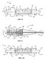
- FIG. 6is a schematic cross-sectional diagram of an example embodiment of a mechanical splice assembly according to the present invention, showing the index-matching gel held in the assembly, the nanostructure optical fiber cable prior to being incorporated into the assembly;
- FIG. 7is a schematic cross-sectional diagram of the ferrule of FIG. 6 ;
- FIG. 8is the same mechanical splice assembly as shown in FIG. 6 , but now with the nanostructure optical fiber cable incorporated into the assembly;
- FIG. 9is a schematic cross-sectional diagram of a simplified fiber optic connector according to the present invention that includes the mechanical splice assembly and index-matching gel of the present invention
- FIG. 10is a schematic cross-sectional diagram of another example embodiment of a mechanical splice assembly for forming a mechanical splice between two fibers;
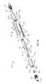
- FIG. 11is an exploded view of an example of a mechanical splice assembly
- FIG. 12is a perspective view of the completed assembly that also shows a cross-section of the assembly
- FIG. 13is a close-up cross-sectional view shown in FIG. 12 ;
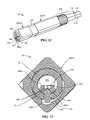
- FIG. 14Ais an end-on exploded view of the splice assembly shown in FIG. 11 ;
- FIG. 14Bis a close-up view of the bottom member of the splice assembly showing the arrangement of the glass rods in the member channel to form the fiber channel, and also showing the index-matching gel of the present invention disposed in the fiber channel;
- FIG. 15is a perspective view of the completed mechanical splice assembly.
- nanostructure optical fibersthere are a number of “nanostructure” (or “holey”) optical fibers on the market today that have one or more regions with periodically or aperiodically arranged small holes or voids, which make the fiber extremely bend insensitive.
- One type of nanostructure optical fiber developed by Corning, Inc.has an annular ring of non-periodic airlines (of diameter ⁇ 1 ⁇ 10 ⁇ 7 m) that extend longitudinally (axially) along the length of the fiber.
- the region with the ring of airlineshas a reduced apparent or average index of refraction, because air has an index of refraction of approximately 1 compared to the fused silica matrix refractive index of approximately 1.46.
- the ring of airlinesis positioned to create a refractive index profile that enables superior bend performance (optically) and significantly smaller minimum bend radius specifications.
- nanostructure optical fibersin combination with index-matching material, however, can be problematic.
- Certain index-matching materialsare commonly used for non-nanostructure optical fibers. However, such materials could possibly migrate (or “wick”) into the airlines (voids) from the fiber end-face over time. This movement may also occur with variations in temperature. Filling the airlines with a material index-matched to silica raises their index of refraction from approximately 1 to approximately 1.46, resulting in a change in the fiber index profile, which leads to increased optical loss when the fiber is bent. This reduces or eliminates an important property of enhanced bend performance of the nanostructure fiber.
- the fiber attenuationis increased substantially when the holes are filled with an index-matching material.
- the index-matching gel of the present inventionis suitable for use in connection with nanostructure optical fibers, and in particular for forming mechanical splices with one or more of such fibers in mechanical splice assemblies used in fiber optic connectors.
- FIG. 1is a schematic side view of a section of an example embodiment of nanostructure optical fiber cable 110 that includes a nanostructure optical fiber 112 with a protective cover 114 .
- Nanostructure optical fiber 112has an end 120 and a central axis A F .
- FIG. 2is a schematic cross-section of cable 110 as viewed along the direction 2 - 2 in FIG. 1 .
- Nanostructure optical fiber cable 110can include, for example, any one of the various types of nanostructure optical fibers 112 , such as any of the so-called “holey” fibers, or those described in the above-mentioned Corning nanostructure fiber patents and patent applications.
- nanostructure optical fiber 112includes a core region (“core”) 220 , a nanostructured region 230 surrounding the core, and a cladding region 240 (“cladding”) surround the nanostructured region.
- corecore region
- claddingcladding region
- Other ring-type configurations for nanostructure optical fiber 112are also known.
- nanostructured region 230comprises a glass matrix (“glass”) 231 having formed therein non-periodically disposed holes (also called “voids” or “airlines”) 232 , such as the example voids shown in detail in the magnified inset of FIG. 2 .
- voids 232may be periodically disposed, such as in a photonic crystal optical fiber, wherein the voids typically have diameters in between about 1 ⁇ 10 ⁇ 6 m and 1 ⁇ 10 ⁇ 5 m.
- Voids 232may also be non-periodic airlines.
- glass 231is fluorine-doped while in another example embodiment the glass is undoped pure silica.
- non-periodically disposedor “non-periodic distribution,” it is meant that when one takes a cross-section of the optical fiber (such as shown in FIG. 2 ), the voids 232 are randomly or non-periodically distributed across a portion of the fiber.
- Cross sections similar to FIG. 2 taken at different points along the length of nanostructure optical fiber 110will reveal different cross-sectional hole patterns, i.e., various cross-sections will have different hole patterns, wherein the distributions of holes and sizes of holes do not match. That is, the holes are non-periodic, i.e., they are not periodically disposed within the fiber structure. These holes are stretched (elongated) along the length (i.e.
- the holesextend less than a few meters, and in many cases less than 1 meter along the length of the fiber.
- non-periodically disposed holes/voids 232are employed in nanostructured region 230 , it is desirable in one example embodiment that they be formed such that greater than 95% of and preferably all of the holes exhibit a mean hole size in the cladding for the optical fiber which is less than 1550 nm, more preferably less than 775 nm, most preferably less than about 390 nm. Likewise, it is preferable that the maximum diameter of the holes in the fiber be less than 7000 nm, more preferably less than 2000 nm, and even more preferably less than 1550 nm, and most preferably less than 775 nm.
- the fibers disclosed hereinhave fewer than 5000 holes, in some embodiments also fewer than 1000 holes, and in other embodiments the total number of holes is fewer than 500 holes in a given optical fiber perpendicular cross-section.
- the most preferred fiberswill exhibit combinations of these characteristics.
- one particularly preferred embodiment of optical fiberwould exhibit fewer than 200 holes in the optical fiber, the holes having a maximum diameter less than 1550 nm and a mean diameter less than 775 nm, although useful and bend resistant optical fibers can be achieved using larger and greater numbers of holes.
- the hole number, mean diameter, max diameter, and total void area percent of holescan all be calculated with the help of a scanning electron microscope at a magnification of about 800 ⁇ to about 4000 ⁇ and image analysis software, such as ImagePro, which is available from Media Cybernetics, Inc. of Silver Spring, Md., USA.
- holes/voids 232can contain one or more gases, such as argon, nitrogen, or oxygen, or the holes can contain a vacuum with substantially no gas; regardless of the presence or absence of any gas, the refractive index of the hole-containing region is lowered due to the presence of the holes.
- the holescan be non-periodically or non-periodically disposed, while in other embodiments the holes are disposed periodically.
- the plurality of holescomprises a plurality of non-periodically disposed holes and a plurality of periodically disposed holes.
- the depressed indexcan also be provided by downdoping the glass in the hole-containing region (such as with fluorine) or updoping one or both of the surrounding regions.
- Nanostructured region 230can be made by methods that utilize preform consolidation conditions, which are effective to trap a significant amount of gases in the consolidated glass blank, thereby causing the formation of voids in the consolidated glass optical fiber preform. Rather than taking steps to remove these voids, the resultant preform is used to form an optical fiber with voids, or holes, therein.
- the diameter of a holeis the longest line segment whose endpoints are disposed on the silica internal surface defining the hole when the optical fiber is viewed in perpendicular cross-section transverse to the optical fiber central axis A F .
- An example nanostructure fiber 112was analyzed in connection with using the index-matching gel 100 of the present invention.
- SEM analysis of the end face of an example nanostructure optical fiber 112showed an approximately 4.5 micron radius GeO2-SiO2 void-free core (having an index of approximately +0.34 percent delta verses silica) surrounded by a 11 micron outer radius void-free near clad region surrounded by 14.3 micron outer radius non-periodic void-containing cladding region (ring thickness of approximately 3.3 microns), which is surrounded by a void-free pure silica outer cladding having an outer diameter of about 125 microns (all radial dimensions measured from the center of the optical fiber).
- the nanostructure regioncomprised approximately 2.5 percent regional area percent holes (100 percent N2 by volume) in that area with an average diameter of 0.28 microns and the smallest diameter holes at 0.17 microns and a maximum diameter of 0.48 microns, resulting in about 130 total number of holes in the fiber cross-section.
- the total fiber void area percent(area of the holes divided by total area of the optical fiber cross-section ⁇ 100) was about 0.05 percent.
- Optical properties for this fiberwere 0.36 and 0.20 dB/Km at 1310 and 1550 nm, respectively, and a 22 meter fiber cable cutoff of about 1250 nm, thereby making the fiber single mode at wavelengths above 1250 nm.
- An example of a common index-matching material used today with conventional (i.e., non-nanostructured) optical fibersis a low-viscosity index polymer with a molecular weight typically less than 30,000 Daltons to which is added a small amount of gelling agent, such as fumed silica or metal soap to make the gel phixotropic.
- gelling agentsuch as fumed silica or metal soap to make the gel phixotropic.
- molecular weightis the measured apparent molecular weight as measured against a polystyrene standard.
- the index-matching gel of the present inventionis made up almost entirely of at least one polymer component, so that certain properties of the gel, such as viscosity and molecular weight, are ostensibly defined by the at least one polymer component.
- certain properties of the gelsuch as viscosity and molecular weight
- such propertiesare attributable to either the at least one polymer component or the gel, as one skilled in the art will appreciate.
- index-matching gels having certain refractive indicescan be formed using polymers, and methods for their production are known in the prior art, the importance of higher molecular weight (Mw) gels in connection with nanostructure optical fibers has heretofore not been recognized.
- Mwmolecular weight
- conventional index-matching materialsare not suitable for fiber splicing when one of the optical fibers is a nanostructure optical fiber. This is because the index-matching material could fills voids 232 at end 120 of the nanostructure optical fiber and thus change the effective refractive index of nanostructured region 232 at the fiber end. This, in turn, leads to undesirable loss at the fiber-fiber interface, as well as a deterioration in bend performance.
- the present inventionincludes mechanical splice assembly 10 (described below in connection with FIG. 6 through FIG. 8 ) and a connector 300 (described below in connection with FIG. 9 ) that include an index-matching gel 100 according to the present invention, wherein the gel is constituted in one example embodiment with at least one polymer component having a sufficient viscosity ⁇ so that the gel does not substantially fill voids 232 at fiber end 120 , as illustrated in FIG. 3A .
- index-matching gel 100is capable of migrating into voids 232 to a depth D M as measured from fiber end 120 .
- the gel of the present invention that migrates into voids 232only does so to a limited maximum depth D M that does not substantially impair the functionality of fiber relative to its intended use.
- nanostructure optical fiber 112may be used in a connector (i.e., is connectorized), and depth D M may be such that the maximum extent of the gel migration does not extend to beyond the connector housing, or beyond the connector boot back end (which in an example embodiment of a present-day fiber optic connector would be about 40 mm from fiber end 120 ).
- index-matching gel 100migrates into the voids to a depth D M that does not extend beyond 5.08 cm (i.e., 2 inches) from either of the first or second splice assembly ends.
- An example embodiment gel 100 of the present inventionis based on a siloxane polymer having the following general chemical formula:
- R 1 , R 2 , R 3 and R 4can be the same, or can be different.
- the groupmay include a C 1 -C 12 alkyl group (e.g. methyl, ethyl and the like), a C 1 -C 12 alkoxy group (e.g. methoxy, ethyoxy and the like), an aromatic group, a halogenated (F, Cl, Br; most preferred Cl) aromatic or alkyl group, or trimethylsiloxy.
- the refractive index of a polysiloxane polymer componentis adjustable by the inclusion of diphenyl siloxane or phenyl-methyl siloxane.
- diphenyl siloxane or phenyl-methyl siloxaneexamples include dimethylsiloxane-phenylmethylsiloxane co-polymers or dimethylsiloxane-diphenylsiloxane co-polymers.
- mixtures of two or more polymerspreferably, silicones, having different viscosities, at least one having a higher and one having a lower viscosity, and different refractive indices, at least one having a higher and one having a lower refractive index, can be mixed to, can be mixed to obtain the correct viscosity and a refractive index to match core 220 .
- These formulationsmay not perfectly match the refractive index of core 220 , but the matches can be made sufficiently close (at a wavelength of operation of the fiber) to avoid significant attenuation of the signal over the short path lengths within fiber optic connectors.
- a polydimethyl siloxane/methylphenylsiloxane co-polymerhas a refractive index that substantially matches that of fiber core 220 while rendering the index matching gel transparent or substantially transparent at the wavelengths used in optical fiber communications.
- Other co- or ter-polymers that contain the appropriate proportion of aryl and alkyl groupsalso produce gels 100 that are transparent and index matching.
- the at least one polymer component in gel 100has a molecular weight Mw such that its viscosity at 25° C., when applied to the connector/nanostructured fiber, is in a range from 3 to 100 Pa-s, preferably 5 to 50 Pa-s, most preferably 5 to 20 Pa-s.
- An example embodiment of siloxane polymer component of gel 100has a molecular weight Mw >25,000 daltons.
- the siloxane polymer component of gel 100has a molecular weight in the range from 25, 000 daltons ⁇ Mw ⁇ 200, 000 daltons.
- the molecular weight Mw of gel 100(or more particularly, the polymer component of the gel) is optimized for a particular type of nanostructure optical fiber 112 .
- a nanostructure optical fiber 112 that includes photonic crystalshas relatively large voids (e.g., diameter ⁇ 1 ⁇ 10 ⁇ 6 to ⁇ 1 ⁇ 10 ⁇ 5 m) and so may require a gel having a molecular weight Mw on the high-end of the range.
- the liquid polymersmay comprise a composition capable of being further polymerized or crosslinked by means of heat or actinic radiation.
- Such compositionsmay contain monomers, oligomers, and higher molecular weight, liquid pre-polymers (including liquid silicone pre-polymers) having the required refractive index that have attached thereto vinyl, acrylate, epoxy, isocyanate, silane, hydrosilane, and other polymerizable functional groups well known to those skilled in the polymer art.
- polymerizable compositionsalso contain initiators, catalysts, accelerators, sensitizers, and the like to facilitate the polymerization process.
- polymeric index matching materialsselected from the group of polymers or polymer mixtures (polymer components) such as polybutenes, (meth)acrylates, acrylics, epoxies, polyesters, polyethers, polycaprolactones, polycarbonates, polybutadienes, polyurethanes, natural hydrocarbons, and other polymers well known to those skilled in the polymer art, including blends and copolymers of the above.
- polymers or polymer mixturespolymer components
- polymer componentssuch as polybutenes, (meth)acrylates, acrylics, epoxies, polyesters, polyethers, polycaprolactones, polycarbonates, polybutadienes, polyurethanes, natural hydrocarbons, and other polymers well known to those skilled in the polymer art, including blends and copolymers of the above.
- gel 100is index-matched to provide the least possible amount of optical loss from reflection at fiber-fiber interface 122 formed by stub-fiber end 72 and nanostructure optical fiber end 120 .
- gel 100may be index matched (or non-index matched, as the case may be) and applied to end 120 of nanostructure optical fiber 100 to “seal” the end to prevent the ingress of other materials in the ambient environment. This may be done, for example, in connection with the treatment of cable ends or hardware cable stubs during shipment or installation to prevent migration of water, oils, etc, into voids 232 at open fiber end 120 .
- index-matching gel 100 of the present inventionwas compared to a prior art index-matching gel.
- the viscosity for the polymers usedwas measured at approximately 25° C. in a cone and plate rheometer at a shear rate ⁇ of 12 sec ⁇ 1 .
- the prior art index-matching gelwas a low viscosity polymer made up of dimethyl-diphenyl silicone copolymer and having a viscosity of approximately 1.5 Pa-s, a weight average molecular weight Mw of approximately 24000 daltons, and a polydispersity of approximately 1.7 (measured vs. polystyrene standard).
- the gel 100 of the present inventionhad a polymer component in the form of a high viscosity polymer made up of dimethyl-diphenyl silicone copolymer with a viscosity of approximately 8 Pa-s, a weight average molecular weight of approximately 49000 daltons, and a polydispersity of approximately 2.1 (measured vs. polystyrene standard).
- both index matching gelswere used in respective field installable connectors.
- the connectorswere cycled between ⁇ 40 and +75° C. following Bellcore GR326 temperature cycling for 14 days, and a macrobend attenuation increase for a 10 mm diameter bend at the end of the connector boot, which is approx 40 mm from the fiber end-face, was measured.
- the macrobend attenuation increasewas ⁇ 0.05 dB/turn, while for the low viscosity polymer-based prior art gel, the macrobend attenuation was>0.5 dB/turn.
- aspects of the present inventioninclude mechanical splice assemblies, and fiber optic connectors having such splice assemblies, that utilize the index-matching gel of the present invention.
- the example embodiment of the mechanical splice assemblies and fiber optic connectors of the present invention as described hereinbeloware based on simplified assemblies and connectors in order to illustrate the underlying principles of the invention.
- One skilled in the artwill recognize that the assemblies and connectors of the present invention as described herein can be implemented with a number of specific types of fiber optic connectors, such as those described in U.S. Pat. Nos. 4,923,274, 6,816,661 and 7,104,702, which patents are incorporated by reference herein.
- FIG. 6is a schematic cross-sectional view of an example embodiment of a mechanical splice assembly 10 according to the present invention.
- Assembly 10includes a body 20 such as a ferrule or other type of housing.
- Body 20is shown by itself in FIG. 7 for ease of illustration and explanation and is also referred to as “ferrule 20 ” for this and other embodiments below.
- ferrule 20includes first and second ends 22 and 24 , and outer surface 26 .
- Ferrule 20includes an interior chamber 30 with front and rear open ends 32 and 34 that open to respective front and rear channels 42 and 44 .
- Front channel 42includes an open end 43 at ferrule end 22
- rear channel 44has an open end 45 at ferrule end 24 .
- Optical fiber channel 42is sized to accommodate a bare optical fiber
- optical fiber channel 44is sized to accommodate a field optical fiber that includes its protective cover, as discussed below.
- Assembly 10further includes frontward and rearward guides 52 and 54 arranged within chamber 30 at front and rear openings 32 and 34 , respectively.
- Guides 52 and 54are sized to pass a bare optical fiber and support the optical fiber within chamber 30 .
- assembly 10includes a retaining ring 60 on outer surface 26 at or near ferrule end 22 so that the assembly can reside within a ferrule holder of a fiber optic connector, as discussed below.
- assembly 10includes a section of optical fiber 70 , referred to as a “fiber stub,” arranged in front channel 42 and that passes through front guide 52 such that a portion of the fiber stub protrudes part way into chamber 30 .
- Fiber stub 70includes a front end 72 that is polished and flush with ferrule end 22 .
- Fiber stub 70also includes a rear end 74 that resides within chamber 30 and that is flat or cleaved at an angle.
- Chamber 30is filled with an index-matching high-molecular-weight gel 100 , which is described in greater detail below.
- Fiber stub 70may be formed from either a nanostructure optical fiber or a non-nanostructure optical fiber.
- mechanical splice assembly 10is adapted to accommodate, via ferrule end 24 , an end-portion 108 of nanostructure optical fiber cable 110 , including protective cover 114 .
- Nanostructure optical fiber end 120is preferably flat or cleaved when used in assembly 10 .
- FIG. 8is a schematic side view similar to FIG. 6 , illustrating the nanostructure optical fiber cable 110 incorporated into mechanical splice assembly 10 .
- Nanostructure optical fiber 112is introduced into rear channel 44 at ferrule rear end 24 and is passed through rear guide 54 until nanostructure optical fiber end 120 interfaces with fiber stub rear end 74 in chamber 30 at fiber-fiber interface 122 .
- Nanostructure optical fiber cable 110is also held in rear channel 44 , which is sized to fit the cable with outer jacket 114 .
- outer jacket 114is stripped back by a length corresponding to the distance D S between fiber stub rear end 74 and rear chamber opening 34 ( FIG. 6 ).
- stub fiber 72may be formed from a section a nanostructure optical fiber, and the field optical fiber described above as a nanostructure optical fiber cable 110 may be a non-nanostructure optical fiber cable.
- FIG. 9is a schematic cross-sectional diagram of a simplified fiber optic connector 300 according to the present invention that includes mechanical splice assembly 10 .
- Connector 300includes a connector housing 302 having an interior 301 , front and back ends 304 and 306 and a central axis Ac that runs through the interior.
- Housing 302houses in interior 301 a ferrule holder 310 that has a front end 311 with a front-end portion 312 sized to accommodate mechanical splice assembly 10 .
- Ferrule holder 310also includes a back end portion 314 with a back end 313 sized to receive a support ferrule 320 that in turn is sized to hold a field fiber cable—which in the present example embodiment is a nanostructured fiber cable 110 .
- Connector 300also includes a crimp ring 330 arranged around ferrule holder 310 at back end 314 .
- Crimp ring 330is crimpled to cause the back portion of ferrule holder 310 and support ferrule 320 held therein to squeeze nanostructure optical fiber 110 in order to provide strain-relief.
- a flexible connector tail 350is connected to housing back end 306 and to nanostructure optical fiber cable 10 to provide further stress relief.
- Housing front end 304includes an alignment member 370 that serves to align and hold connector 300 to another connector or to the device port to which connector 300 is to be connected.
- Connector 300is particularly well-suited for use in the field where nanostructure optical fiber cables are used as field cables.
- Connector 300can be field-installed on a nanostructure field cable using the same or similar techniques used to field-install conventional SC, LC and ST®-compatible connectors, such as for example Corning UniCam® Connectors, made by Coming Cable Systems, Hickory, N.C.
- FIG. 10is a schematic, cross-sectional diagram of another example embodiment of a mechanical splice assembly 10 .
- Body 20 of FIG. 12is similar to that shown in FIG. 8 , but wherein optical fiber channels 42 and 44 are each sized to accommodate the fiber protective cover.
- depth D M( FIG. 3B ) does not extend beyond either of the first or second splice assembly ends 22 and 24 . In another example embodiment, depth D M does not extend beyond 5.08 cm from either of the first or second splice assembly ends 22 and 24 .
- An example mechanical splice assembly 10such as shown in the generalized configuration in FIG. 10 includes the CamSpliceTM mechanical splice assembly available from Coming Cable Systems, Inc., Hickory, N.C.
- Mechanical splice assembly 10 of FIG. 11shows an example of a CamSpliceTM mechanical splice assembly 10 .
- FIG. 12is a perspective cut-away view of the completed assembly, and
- FIG. 13is an end-on view of the cross-section shown in FIG. 12 .
- Mechanical splice assembly 10 of FIG. 11includes body 20 , which is referred to in the present example as “inner housing” 20 , which includes first (front) and second (back) sections 20 A and 20 B separated by ring 60 on outer surface 26 .
- Housing sections 20 A and 20 Binclude respective bottom apertures 21 A and 21 B.
- Two outer housing sections 402 A and 402 B referred to hereinafter as front and back “cam sections”slide over respective threaded ends inner housing ends 22 and 24 to cover front and back inner housing sections 20 A and 20 B.
- Each cam section 402 A and 402 Bincludes an eccentric interior region 404 A and 404 B defined by respective inner surfaces 405 A and 405 B, which surfaces include respective detents 406 A and 406 B.
- FIG. 14Ais an exploded end-on view of splice assembly 418 .
- Splice assembly 418includes a bottom member 420 having a top surface 422 with a channel 426 formed therein. Channel 426 has a bottom 427 .
- Bottom member 420also has a curved bottom surface 430 that generally conforms to housing inner surface 31 and that includes two “keels” or “ribs” 432 sized to fit through inner housing apertures 21 A and 21 B;
- Splice assemblyalso includes two rods 440 (e.g., glass rods) that reside in channel 426 and that occupy most of the channel.
- rods 440e.g., glass rods
- rods 440 and channel bottom 427define a fiber channel 442 sized to accommodate bare optical fibers (e.g., fibers 70 and 112 ) in an end to end arrangement like that shown in FIG. 10 .
- bare optical fiberse.g., fibers 70 and 112
- one or both of fibers 70 and 112are nano-engineered fibers.
- Splice assembly 418also includes a top member 450 with a flat bottom surface 452 that includes a nub or bump 454 .
- Top member 450resides with flat bottom surface 452 atop flat top surface of bottom member 420 and covering channel 426 .
- Nub 454fits between glass rods 440 and serves to keep the rods fixed in place within channel 426 .
- Mechanical splice assembly 10 of FIG. 11also includes two fiber guides 460 (e.g., ferrules) that fit within respective ends 22 and 26 of inner housing and that include a central aperture sized to accommodate optical fiber 112 .
- Assembly 10also includes threaded caps 470 that have a central aperture 472 sized to accommodate cable 110 and that threadedly engage with respective inner housing ends 22 and 24 to secure fiber guides 460 to their respective cam sections 402 A and 402 B. Threaded caps 470 define respective splice assembly ends.
- splice assembly 418is assembled with gel 100 included in fiber channel 442 (see FIG. 14B ). Assembly 418 is then disposed within interior chamber 30 of inner housing 20 . Once so arranged, the optical fibers 70 and 112 to be spliced can then be inserted into opposite ends of fiber channel 442 at opposite ends of splice assembly 418 so that the respective end faces 74 and 120 meet to form fiber-fiber interface 122 that includes index-matching gel 100 between the end faces. Front and back cam sections 402 A and 402 B are then placed over inner housing front and back sections 20 A and 20 B and rotated relative to the inner housing.
Landscapes
- Physics & Mathematics (AREA)
- General Physics & Mathematics (AREA)
- Optics & Photonics (AREA)
- Mechanical Coupling Of Light Guides (AREA)
Abstract
Description

wherein R1, R2, R3and R4can be the same, or can be different. The group may include a C1-C12alkyl group (e.g. methyl, ethyl and the like), a C1-C12alkoxy group (e.g. methoxy, ethyoxy and the like), an aromatic group, a halogenated (F, Cl, Br; most preferred Cl) aromatic or alkyl group, or trimethylsiloxy.
Claims (31)
Priority Applications (2)
| Application Number | Priority Date | Filing Date | Title |
|---|---|---|---|
| US12/221,040US7742670B2 (en) | 2007-10-01 | 2008-07-30 | Index-matching gel for nanostructure optical fibers and mechanical splice assembly and connector using same |
| PCT/US2009/004264WO2010014173A1 (en) | 2008-07-30 | 2009-07-23 | Index-matching gel for nanostructure optical fibers and mechanical splice assembly and connector using same |
Applications Claiming Priority (3)
| Application Number | Priority Date | Filing Date | Title |
|---|---|---|---|
| US99716507P | 2007-10-01 | 2007-10-01 | |
| US11/985,509US7628548B2 (en) | 2007-10-01 | 2007-11-15 | Index-matching gel for nanostructure optical fibers and mechanical splice assembly and connector using same |
| US12/221,040US7742670B2 (en) | 2007-10-01 | 2008-07-30 | Index-matching gel for nanostructure optical fibers and mechanical splice assembly and connector using same |
Related Parent Applications (1)
| Application Number | Title | Priority Date | Filing Date |
|---|---|---|---|
| US11/985,509Continuation-In-PartUS7628548B2 (en) | 2007-10-01 | 2007-11-15 | Index-matching gel for nanostructure optical fibers and mechanical splice assembly and connector using same |
Publications (2)
| Publication Number | Publication Date |
|---|---|
| US20090087151A1 US20090087151A1 (en) | 2009-04-02 |
| US7742670B2true US7742670B2 (en) | 2010-06-22 |
Family
ID=41095923
Family Applications (1)
| Application Number | Title | Priority Date | Filing Date |
|---|---|---|---|
| US12/221,040Expired - Fee RelatedUS7742670B2 (en) | 2007-10-01 | 2008-07-30 | Index-matching gel for nanostructure optical fibers and mechanical splice assembly and connector using same |
Country Status (2)
| Country | Link |
|---|---|
| US (1) | US7742670B2 (en) |
| WO (1) | WO2010014173A1 (en) |
Cited By (25)
| Publication number | Priority date | Publication date | Assignee | Title |
|---|---|---|---|---|
| US20100303419A1 (en)* | 2009-05-29 | 2010-12-02 | Seldon David Benjamin | Fiber end face void closing method, a connectorized optical fiber assembly, and method of forming same |
| US8596884B2 (en) | 2011-06-28 | 2013-12-03 | Corning Cable Systems Llc | Optical fiber mechanical splice connector systems and methods of coupling optical fibers |
| US8981305B2 (en) | 2011-05-12 | 2015-03-17 | University Of Florida Research Foundation, Inc. | Index of refraction matched nanoparticles and methods of use |
| USRE46098E1 (en)* | 2009-11-20 | 2016-08-09 | Corning Incorporated | Optical fiber illumination systems and methods |
| US11054583B2 (en)* | 2017-06-06 | 2021-07-06 | Commscope Technologies Llc | Optical fiber alignment device with self-healing refractive index-matching gel |
| US11187859B2 (en) | 2017-06-28 | 2021-11-30 | Corning Research & Development Corporation | Fiber optic connectors and methods of making the same |
| US11215768B2 (en) | 2017-06-28 | 2022-01-04 | Corning Research & Development Corporation | Fiber optic connectors and connectorization employing adhesive admitting adapters |
| US11294133B2 (en) | 2019-07-31 | 2022-04-05 | Corning Research & Development Corporation | Fiber optic networks using multiports and cable assemblies with cable-to-connector orientation |
| US11300746B2 (en) | 2017-06-28 | 2022-04-12 | Corning Research & Development Corporation | Fiber optic port module inserts, assemblies and methods of making the same |
| US11487073B2 (en) | 2019-09-30 | 2022-11-01 | Corning Research & Development Corporation | Cable input devices having an integrated locking feature and assemblies using the cable input devices |
| US11536921B2 (en) | 2020-02-11 | 2022-12-27 | Corning Research & Development Corporation | Fiber optic terminals having one or more loopback assemblies |
| US11604320B2 (en) | 2020-09-30 | 2023-03-14 | Corning Research & Development Corporation | Connector assemblies for telecommunication enclosures |
| US11650388B2 (en) | 2019-11-14 | 2023-05-16 | Corning Research & Development Corporation | Fiber optic networks having a self-supporting optical terminal and methods of installing the optical terminal |
| US11668890B2 (en) | 2017-06-28 | 2023-06-06 | Corning Research & Development Corporation | Multiports and other devices having optical connection ports with securing features and methods of making the same |
| US11686913B2 (en) | 2020-11-30 | 2023-06-27 | Corning Research & Development Corporation | Fiber optic cable assemblies and connector assemblies having a crimp ring and crimp body and methods of fabricating the same |
| US11703646B2 (en) | 2017-06-28 | 2023-07-18 | Corning Research & Development Corporation | Multiports and optical connectors with rotationally discrete locking and keying features |
| US11880076B2 (en) | 2020-11-30 | 2024-01-23 | Corning Research & Development Corporation | Fiber optic adapter assemblies including a conversion housing and a release housing |
| US11886010B2 (en) | 2019-10-07 | 2024-01-30 | Corning Research & Development Corporation | Fiber optic terminals and fiber optic networks having variable ratio couplers |
| US11927810B2 (en) | 2020-11-30 | 2024-03-12 | Corning Research & Development Corporation | Fiber optic adapter assemblies including a conversion housing and a release member |
| US11947167B2 (en) | 2021-05-26 | 2024-04-02 | Corning Research & Development Corporation | Fiber optic terminals and tools and methods for adjusting a split ratio of a fiber optic terminal |
| US11994722B2 (en) | 2020-11-30 | 2024-05-28 | Corning Research & Development Corporation | Fiber optic adapter assemblies including an adapter housing and a locking housing |
| US12019279B2 (en) | 2019-05-31 | 2024-06-25 | Corning Research & Development Corporation | Multiports and other devices having optical connection ports with sliding actuators and methods of making the same |
| US12044894B2 (en) | 2018-12-28 | 2024-07-23 | Corning Research & Development Corporation | Multiport assemblies including mounting features or dust plugs |
| US12271040B2 (en) | 2017-06-28 | 2025-04-08 | Corning Research & Development Corporation | Fiber optic extender ports, assemblies and methods of making the same |
| US12372727B2 (en) | 2020-10-30 | 2025-07-29 | Corning Research & Development Corporation | Female fiber optic connectors having a rocker latch arm and methods of making the same |
Families Citing this family (19)
| Publication number | Priority date | Publication date | Assignee | Title |
|---|---|---|---|---|
| US8175437B2 (en)* | 2008-02-07 | 2012-05-08 | Corning Incorporated | Microstructured transmission optical fiber |
| US20100124394A1 (en)* | 2008-11-19 | 2010-05-20 | David Wayne Meek | Process for connecting fibers and connected optical assembly |
| CN102087386A (en)* | 2009-12-07 | 2011-06-08 | 鸿富锦精密工业(深圳)有限公司 | Optical fiber coupling connector and electronic device |
| WO2011116521A1 (en)* | 2010-03-24 | 2011-09-29 | 深圳日海通讯技术股份有限公司 | Field installable optical-fiber connector |
| US10414839B2 (en) | 2010-10-20 | 2019-09-17 | Sirrus, Inc. | Polymers including a methylene beta-ketoester and products formed therefrom |
| EP2726923A4 (en) | 2011-06-30 | 2015-04-15 | Corning Cable Systems Shanghai Co Ltd | Fiber optic connectors,cable assemblies and method for making the same |
| US8805141B2 (en)* | 2011-10-07 | 2014-08-12 | Corning Incorporated | Optical fiber illumination systems and methods |
| CA2853073A1 (en) | 2011-10-19 | 2013-04-25 | Bioformix Inc. | Methylene beta-diketone monomers, methods for making methylene beta-diketone monomers, polymerizable compositions and products formed therefrom |
| BR112014009850A2 (en) | 2011-10-25 | 2017-04-18 | Corning Cable Systems (Shanghai) Co Ltd | fiber optic connectors, cable harness, and method for doing the same |
| MX338075B (en) | 2012-02-07 | 2016-04-01 | Tyco Electronics Corp | Optical fiber connection system including optical fiber alignment device. |
| CA2869112A1 (en) | 2012-03-30 | 2013-10-03 | Bioformix Inc. | Composite and laminate articles and polymerizable systems for producing the same |
| EP3848402A1 (en) | 2012-03-30 | 2021-07-14 | Sirrus, Inc. | Ink and coating formulations and polymerizable systems for producing the same |
| WO2013181600A2 (en)* | 2012-06-01 | 2013-12-05 | Bioformix Inc. | Optical material and articles formed therefrom |
| EP2920231B1 (en) | 2012-11-16 | 2020-05-06 | Sirrus, Inc. | Plastics bonding systems and methods |
| CN105164797B (en) | 2012-11-30 | 2019-04-19 | 瑟拉斯公司 | Composite compositions for electronic applications |
| CN105264415A (en)* | 2013-04-02 | 2016-01-20 | 泰科电子瑞侃有限公司 | Self-writable waveguide for fiber connectors and related methods |
| EP2977802A1 (en)* | 2014-07-25 | 2016-01-27 | Siemens Aktiengesellschaft | Method for protecting a connector unit |
| US9334430B1 (en) | 2015-05-29 | 2016-05-10 | Sirrus, Inc. | Encapsulated polymerization initiators, polymerization systems and methods using the same |
| US9217098B1 (en) | 2015-06-01 | 2015-12-22 | Sirrus, Inc. | Electroinitiated polymerization of compositions having a 1,1-disubstituted alkene compound |
Citations (40)
| Publication number | Priority date | Publication date | Assignee | Title |
|---|---|---|---|---|
| GB2135077A (en) | 1983-02-10 | 1984-08-22 | Raychem Corp | Joining optic fibres |
| EP0195355A2 (en) | 1985-03-12 | 1986-09-24 | Toray Silicone Company Limited | Refractive-index-coupling elastic composition for optical communication fiber joints |
| US5002357A (en) | 1989-11-09 | 1991-03-26 | Square D Company | Optical fiber coupler |
| EP0457903A1 (en) | 1989-12-11 | 1991-11-27 | Sumitomo Electric Industries, Ltd. | Photocurable resin composition and plastic-clad optical fiber using the same |
| US5079300A (en) | 1989-03-01 | 1992-01-07 | Raychem Corporation | Method of curing organpolysiloxane compositions and compositions and articles therefrom |
| US5189717A (en) | 1988-04-18 | 1993-02-23 | Minnesota Mining And Manufacturing Company | Optical fiber splice |
| JPH05325225A (en) | 1992-05-19 | 1993-12-10 | Matsushita Electric Ind Co Ltd | Objective lens actuator |
| US5311610A (en) | 1993-03-31 | 1994-05-10 | Bell Communications Research, Inc. | Low-stress coupling of electrooptical device to optical fiber |
| US5347606A (en) | 1992-01-13 | 1994-09-13 | Televerket | Method and an arrangement for splicing optical waveguides |
| US5363461A (en) | 1993-07-20 | 1994-11-08 | Bergmann Ernest E | Field installable optical fiber connectors |
| WO1995031173A1 (en) | 1994-05-13 | 1995-11-23 | The Procter & Gamble Company | Hair care compositions containing dual dispersion of polysiloxane conditioning agent and polysiloxane shine agent |
| US5528718A (en) | 1993-04-16 | 1996-06-18 | Raychem Corporation | Fiber optic cable system including main and drop cables and associated fabrication method |
| US5689607A (en) | 1994-12-08 | 1997-11-18 | Alcatel Cable Interface | Device for holding at least one optical fiber cable, and a splice box making use of the device |
| JPH09325225A (en) | 1996-06-06 | 1997-12-16 | Hitachi Cable Ltd | Light guide unit |
| US5802236A (en) | 1997-02-14 | 1998-09-01 | Lucent Technologies Inc. | Article comprising a micro-structured optical fiber, and method of making such fiber |
| US5930423A (en) | 1997-07-15 | 1999-07-27 | Lucent Technologies Inc. | Semiconductor optical waveguide devices with integrated beam expander coupled to flat fibers |
| US20020061176A1 (en) | 2000-07-21 | 2002-05-23 | Libori Stig Eigil Barkou | Dispersion manipulating fibre |
| JP2003167145A (en) | 2001-11-29 | 2003-06-13 | Fujikura Ltd | Optical fiber and its connection structure and connection method |
| US6648521B2 (en) | 2001-02-23 | 2003-11-18 | Fiber Systems International | Single terminus connector with preterminated fiber and fiber guide tube |
| US6652163B2 (en) | 2001-10-31 | 2003-11-25 | Corning Incorporated | Splice joint and process for joining a microstructured optical fiber and a conventional optical fiber |
| US20040067025A1 (en) | 2002-05-09 | 2004-04-08 | Akira Haraguchi | Optical device |
| EP1441243A1 (en) | 2003-01-24 | 2004-07-28 | Nitto Denko Corporation | Process of manufacturing optical waveguide and connection structure of optical devices |
| US6811328B2 (en) | 2002-05-28 | 2004-11-02 | Agilent Technologies, Inc. | Optical fiber splicing using surface tension |
| US6815520B2 (en) | 2001-03-06 | 2004-11-09 | Shin-Etsu Chemical Co., Ltd. | Addition curing type silicone resin composition |
| JP2005024849A (en) | 2003-07-01 | 2005-01-27 | Hitachi Cable Ltd | Optical fiber connector |
| JP2005024848A (en) | 2003-07-01 | 2005-01-27 | Hitachi Cable Ltd | Optical fiber connector and optical fiber connector |
| EP1507154A1 (en) | 2002-05-17 | 2005-02-16 | Nippon Telegraph and Telephone Corporation | Dispersion shift optical fiber |
| WO2005050273A1 (en) | 2003-11-19 | 2005-06-02 | Tomoegawa Paper Co., Ltd. | Optical connection structure and optical connection method |
| JP2005173575A (en) | 2003-11-19 | 2005-06-30 | Tomoegawa Paper Co Ltd | Optical connection structure and optical connection method thereof |
| US6915053B2 (en) | 2002-11-28 | 2005-07-05 | Sumitomo Electric Industries, Ltd. | Microstructured optical fiber and optical module |
| US6947647B2 (en) | 2003-06-04 | 2005-09-20 | Sempra Fiber Links | Methods for installing fiber optic cable in a building having a gas riser |
| JP2005314541A (en) | 2004-04-28 | 2005-11-10 | Hitachi Chem Co Ltd | Resin composition for optical use, method for producing the same and optical element produced by using the same |
| JP2006030754A (en) | 2004-07-20 | 2006-02-02 | Tomoegawa Paper Co Ltd | OPTICAL CONNECTION STRUCTURE, ITS MANUFACTURING METHOD, AND SUPPORT MEMBER USED FOR THE SAME |
| US20060067632A1 (en) | 2002-11-23 | 2006-03-30 | Crystal Fibre A/S | Splicing and connectorization of photonic crystal fibres |
| WO2006050974A1 (en) | 2004-11-12 | 2006-05-18 | Ccs Technology, Inc. | Method for determining the eccentricity of an optical fiber core, and method and device for connecting optical fibers |
| JP2006221031A (en) | 2005-02-14 | 2006-08-24 | Tomoegawa Paper Co Ltd | Optical connection structure |
| US20060204195A1 (en) | 2003-07-01 | 2006-09-14 | Yoshinori Kurosawa | Optical fiber, optical fiber connecting method, and optical connector |
| US7160972B2 (en)* | 2003-02-19 | 2007-01-09 | Nusil Technology Llc | Optically clear high temperature resistant silicone polymers of high refractive index |
| US20070196055A1 (en) | 2006-02-21 | 2007-08-23 | Hitachi Cable, Ltd. | Optical connector and connection structure of optical fibers |
| US20080056655A1 (en) | 2004-10-25 | 2008-03-06 | Nagase Chemtex Corporation | Sealing Composition and Production Method of Optical Fiber Having Air Holes in the Inside Using the Composition |
Family Cites Families (16)
| Publication number | Priority date | Publication date | Assignee | Title |
|---|---|---|---|---|
| US3767932A (en)* | 1972-09-01 | 1973-10-23 | C Bailey | Remote vehicle starting system |
| US4393817A (en)* | 1976-02-13 | 1983-07-19 | Owen, Wickersham & Erickson | Combustion and pollution control system |
| US4372260A (en)* | 1980-09-26 | 1983-02-08 | Wayne Baker | Engine fluid heater |
| US4398081A (en)* | 1980-10-23 | 1983-08-09 | Mark H. Moad | Stand-by heating/power supply system for a motor vehicle |
| US4415847A (en)* | 1981-08-07 | 1983-11-15 | Energy Development Associates, Inc. | Method and apparatus for supplying cooling liquid to a storage battery |
| US4538134A (en)* | 1982-04-29 | 1985-08-27 | Carey John C | Control apparatus |
| GB8304714D0 (en)* | 1983-02-21 | 1983-03-23 | Ass Elect Ind | Induction motors |
| US4815426A (en)* | 1987-02-26 | 1989-03-28 | Henschel Paul S | Engine heater, small, portable |
| US4906337A (en)* | 1987-03-26 | 1990-03-06 | Palmer David G | Water supply system |
| US5307438A (en)* | 1992-08-13 | 1994-04-26 | Minnesota Mining And Manufacturing Company | Index matching compositions with improved DNG/DT |
| US5285963A (en)* | 1993-04-29 | 1994-02-15 | Llr Technologies, Inc. | Intelligent controller for equipment heater |
| US5853068A (en)* | 1997-03-21 | 1998-12-29 | Wynn Oil Company | Apparatus for exchange of automotive fluids |
| JP4329269B2 (en)* | 2001-02-07 | 2009-09-09 | 住友電気工業株式会社 | Optical fiber connection structure and optical fiber connection method |
| US7104702B2 (en)* | 2004-03-24 | 2006-09-12 | Corning Cable Systems Llc | Field installable optical fiber connector |
| JP4924024B2 (en)* | 2006-12-27 | 2012-04-25 | 日立電線株式会社 | Optical connector |
| US7628548B2 (en)* | 2007-10-01 | 2009-12-08 | Corning Cable Systems Llc | Index-matching gel for nanostructure optical fibers and mechanical splice assembly and connector using same |
- 2008
- 2008-07-30USUS12/221,040patent/US7742670B2/ennot_activeExpired - Fee Related
- 2009
- 2009-07-23WOPCT/US2009/004264patent/WO2010014173A1/enactiveApplication Filing
Patent Citations (45)
| Publication number | Priority date | Publication date | Assignee | Title |
|---|---|---|---|---|
| GB2135077A (en) | 1983-02-10 | 1984-08-22 | Raychem Corp | Joining optic fibres |
| EP0195355A2 (en) | 1985-03-12 | 1986-09-24 | Toray Silicone Company Limited | Refractive-index-coupling elastic composition for optical communication fiber joints |
| US5189717A (en) | 1988-04-18 | 1993-02-23 | Minnesota Mining And Manufacturing Company | Optical fiber splice |
| US5079300A (en) | 1989-03-01 | 1992-01-07 | Raychem Corporation | Method of curing organpolysiloxane compositions and compositions and articles therefrom |
| US5002357A (en) | 1989-11-09 | 1991-03-26 | Square D Company | Optical fiber coupler |
| EP0457903A1 (en) | 1989-12-11 | 1991-11-27 | Sumitomo Electric Industries, Ltd. | Photocurable resin composition and plastic-clad optical fiber using the same |
| US5347606A (en) | 1992-01-13 | 1994-09-13 | Televerket | Method and an arrangement for splicing optical waveguides |
| JPH05325225A (en) | 1992-05-19 | 1993-12-10 | Matsushita Electric Ind Co Ltd | Objective lens actuator |
| US5311610A (en) | 1993-03-31 | 1994-05-10 | Bell Communications Research, Inc. | Low-stress coupling of electrooptical device to optical fiber |
| US5528718A (en) | 1993-04-16 | 1996-06-18 | Raychem Corporation | Fiber optic cable system including main and drop cables and associated fabrication method |
| US5657413A (en) | 1993-04-16 | 1997-08-12 | Raychem Corporation | Sealing assembly for a fiber optic cable and associated fabrication method |
| US5363461A (en) | 1993-07-20 | 1994-11-08 | Bergmann Ernest E | Field installable optical fiber connectors |
| WO1995031173A1 (en) | 1994-05-13 | 1995-11-23 | The Procter & Gamble Company | Hair care compositions containing dual dispersion of polysiloxane conditioning agent and polysiloxane shine agent |
| US5689607A (en) | 1994-12-08 | 1997-11-18 | Alcatel Cable Interface | Device for holding at least one optical fiber cable, and a splice box making use of the device |
| JPH09325225A (en) | 1996-06-06 | 1997-12-16 | Hitachi Cable Ltd | Light guide unit |
| US5802236A (en) | 1997-02-14 | 1998-09-01 | Lucent Technologies Inc. | Article comprising a micro-structured optical fiber, and method of making such fiber |
| US5930423A (en) | 1997-07-15 | 1999-07-27 | Lucent Technologies Inc. | Semiconductor optical waveguide devices with integrated beam expander coupled to flat fibers |
| US20020061176A1 (en) | 2000-07-21 | 2002-05-23 | Libori Stig Eigil Barkou | Dispersion manipulating fibre |
| US6648521B2 (en) | 2001-02-23 | 2003-11-18 | Fiber Systems International | Single terminus connector with preterminated fiber and fiber guide tube |
| US6815520B2 (en) | 2001-03-06 | 2004-11-09 | Shin-Etsu Chemical Co., Ltd. | Addition curing type silicone resin composition |
| US6652163B2 (en) | 2001-10-31 | 2003-11-25 | Corning Incorporated | Splice joint and process for joining a microstructured optical fiber and a conventional optical fiber |
| JP2003167145A (en) | 2001-11-29 | 2003-06-13 | Fujikura Ltd | Optical fiber and its connection structure and connection method |
| US20040067025A1 (en) | 2002-05-09 | 2004-04-08 | Akira Haraguchi | Optical device |
| US6850674B2 (en)* | 2002-05-09 | 2005-02-01 | Sumitomo Electric Industries, Ltd. | Optical device |
| EP1507154A1 (en) | 2002-05-17 | 2005-02-16 | Nippon Telegraph and Telephone Corporation | Dispersion shift optical fiber |
| US6811328B2 (en) | 2002-05-28 | 2004-11-02 | Agilent Technologies, Inc. | Optical fiber splicing using surface tension |
| US20070122095A1 (en) | 2002-11-23 | 2007-05-31 | Crystal Fibre A/S | Splicing and connectorization of photonic crystal fibers |
| US20060067632A1 (en) | 2002-11-23 | 2006-03-30 | Crystal Fibre A/S | Splicing and connectorization of photonic crystal fibres |
| US6915053B2 (en) | 2002-11-28 | 2005-07-05 | Sumitomo Electric Industries, Ltd. | Microstructured optical fiber and optical module |
| EP1441243A1 (en) | 2003-01-24 | 2004-07-28 | Nitto Denko Corporation | Process of manufacturing optical waveguide and connection structure of optical devices |
| US7160972B2 (en)* | 2003-02-19 | 2007-01-09 | Nusil Technology Llc | Optically clear high temperature resistant silicone polymers of high refractive index |
| US6947647B2 (en) | 2003-06-04 | 2005-09-20 | Sempra Fiber Links | Methods for installing fiber optic cable in a building having a gas riser |
| US20060204195A1 (en) | 2003-07-01 | 2006-09-14 | Yoshinori Kurosawa | Optical fiber, optical fiber connecting method, and optical connector |
| JP2005024849A (en) | 2003-07-01 | 2005-01-27 | Hitachi Cable Ltd | Optical fiber connector |
| JP2005024848A (en) | 2003-07-01 | 2005-01-27 | Hitachi Cable Ltd | Optical fiber connector and optical fiber connector |
| WO2005050273A1 (en) | 2003-11-19 | 2005-06-02 | Tomoegawa Paper Co., Ltd. | Optical connection structure and optical connection method |
| JP2005173575A (en) | 2003-11-19 | 2005-06-30 | Tomoegawa Paper Co Ltd | Optical connection structure and optical connection method thereof |
| US20070086707A1 (en) | 2003-11-19 | 2007-04-19 | Masayoshi Suzuki | Optical connection structure and optical connection method |
| EP1686402A1 (en) | 2003-11-19 | 2006-08-02 | Tomoegawa Paper Co. Ltd. | Optical connection structure and optical connection method |
| JP2005314541A (en) | 2004-04-28 | 2005-11-10 | Hitachi Chem Co Ltd | Resin composition for optical use, method for producing the same and optical element produced by using the same |
| JP2006030754A (en) | 2004-07-20 | 2006-02-02 | Tomoegawa Paper Co Ltd | OPTICAL CONNECTION STRUCTURE, ITS MANUFACTURING METHOD, AND SUPPORT MEMBER USED FOR THE SAME |
| US20080056655A1 (en) | 2004-10-25 | 2008-03-06 | Nagase Chemtex Corporation | Sealing Composition and Production Method of Optical Fiber Having Air Holes in the Inside Using the Composition |
| WO2006050974A1 (en) | 2004-11-12 | 2006-05-18 | Ccs Technology, Inc. | Method for determining the eccentricity of an optical fiber core, and method and device for connecting optical fibers |
| JP2006221031A (en) | 2005-02-14 | 2006-08-24 | Tomoegawa Paper Co Ltd | Optical connection structure |
| US20070196055A1 (en) | 2006-02-21 | 2007-08-23 | Hitachi Cable, Ltd. | Optical connector and connection structure of optical fibers |
Non-Patent Citations (20)
| Title |
|---|
| "Arc-fusion Splicing Techniques for Holey Fibers", Takahiro Hamada, Ryuji Suzuki, Katsuhiro Takenaga, Ning Guan, Shoichiro Matsuo and Kuniharu Himeno; Fujikura Technical Review, 2006. |
| "Fabrication of selective injection microstructured optical fibers with a conventional fusion splicer", Limin Xiao, Wei Jin, M. S. Demokan, Hoi L. Ho, Yeuk L. Hoo, and Chunliu Zhao, Oct. 31, 2005 / vol. 13, No. 22 / Optics Express 9014, 9 pages. |
| "Field Installable Connector Optimized for Holey Fiber", Y. Kato, K. Suzuki, and K. Ohsono, Hitachi Cable Ltd., Hitaka Works, 5-1-1 Hitaka, Hitachi, Ibaraki, Japan, Phone +81-294-25-2827, Fax: +81-294-43-7487, E-mail: kato.yoshihisa@hitachi-cable.co.jp, M. Wakasa, Y Nakatani, T. Nishio, and M. Tachikura, Advanced Cable Systems Corp., 5-1-1 Hitaka, Hitachi, Ibaraki, Japan, © 2007 Optical Society of America, OCIS codes: (060.0060) Fiber optics and optical communications; (060-2340) Fiber optics components, 3 pages. |
| "Microstructured fiber splicing", Bruno Bourliaguet, Claude Paré, Frédéric Émond and André Croteau, Dec. 15, 2003/vol. 11, No. 25/Optics Express 3412, 6 pages. |
| "New Core Alignment Fusion Splicer FSM-50S", Shigeru Saito, Katsumi Sasaki, Kenji Takahashi, Koji Ohzawa, Taku Otani and Srachate Chumpol; Fujikura Technical Review, 2005. |
| "Photonic Band Gap Guidance in Optical Fibers", J. C. Knight, et al. Science 282, 1476 (1998); DOI: 10.1126/science.282.5393.1476; www.sciencemag.org, Dec. 18, 2007; 4 pages. |
| "Simply-Structured Optical Terminators using Adhesive Polymer for Fiber Contact", M. Tachikura, M. Wakasa, T. Nishio, Advanced Cable Systems Corp., 5-1-1 HItaka-cho, Hitachi-shi Ibaraki-ken, Japan, Phone +81-294-43-3777, Fax: +81-294-43-1190, tachikura.masao@advanced-cable.co.jp, K. Suzuki, Y. Kato, K. Ohsono, Hitachi Cable Ltd., 5-1-1 HItaka-cho, Hitachi-shi Ibaraki-ken, Japan, N. Hasimoto and T. Furue, Tomoegawa Co., Ltd., 3-1 Tomoe-cho, Suruga-ku, Shizuoka-shi Japan, © 2006 Optical Society of America, OCIS codes: (060.0060) Fiber optics and optical communications; (060.2340) fiber optics components, 3 pages. |
| 8217 Journal of Lightwave Technology 11 (Apr. 1993), No. 4, New York, US, LOGY, vol. 11, No. 4, Apr. 1993 "Real Time Control of Arc Fusion for Optical Fiber Splicing", Wenxin Zheng, 0733-8724/93$03.00 © 1993 IEEE, 6 pages. |
| Electronics and Communications in Japan, Part 2, vol. 71, No. 11,1988, Translated from Denshi Joho Isushin Gakkai Ronbunshi, vol. 70-C, No. 12, Dec. 1987, pp. 1623-1630, XP009028361, "Direct Core Observation Method Using Thermal Radiation of Silica Fibers with Dopants", Toshiaki Katagira, Massao Tachikura, and Koushi Ishihara, Members NTT Transmission Systems Laboratories, Japan 319-11, ISSN8756-663X/88/0011-0077$7.50/0 © 1988 Scripta Technica, Inc., 9 pages. |
| IEICE Trans. Electron., vol. E89-C, No. 2 Feb. 2006, XP-001241540, Paper, "Holey Fibers for Low Bending Loss", Ning Guan a), Member, Katsuaki Izoe, Nonmember, Katsuhiro Takenaga , Ryuji Suzuki , Members, Kazuhiko Aikawa , Nonmember, and Kuniharu Himeno , Member, Copyright © 2006 The Institute of Electronics, Information and Communication Engineers, Manuscript received Jun. 20, 2005, Manuscript revised Sep. 5, 2005, the authors are with the Optics and Electronics Laboratory, Fujikura Ltd., Sakura-shi, 285-8550 Japan. a) E-mail: guan@lab.fujikura.co.jp DOI: 10.1093/ietele/e89-c.2.191, 6 pages. |
| Inoue, et al., "Molecular Weight Evaluation of Poly(dimethylsiloxane) on Solid Surfaces Using Silver Deposition/TOF-SIMS," Analytical Sciences, vol. 20, Dec. 2004, 6 pages. |
| Journal of Lightwave Technology, vol. 23, No. 11, Nov. 2005, "Low-Bending-Loss Single-Mode Fibers for Fiber-to-the-Home", Kuniharu Himeno, Shoichiro Matsuo, Ning Guan, Member, IEEE, and Akira Wada, Member, IEEE, 6 pages. |
| Krzysztof Borzycki , "Holey Fibers-Application Issues", National Institute of Telecommunications, Warsaw, Poland, ICTION 2001. |
| Light Reading-"Holey Fibers!"-Telecom Report, www.lightreading.com/document.asp?doc-id=21449, Nov. 21, 2002. |
| Oe Magazine-guiding light with holey fibers, oe magazine, The SPIE Magazine of Photonics Technologies and Applications, "Guiding Light with Holey Fibers", René Engel Kristiansen, Crystal Fibre A/S, http://oemagazine.com/fromtheMagazine/jun02/tutorial.html, Mar. 21, 2007, 8 pages. |
| Optical Fiber Communication Conference, 1992 Technical Digest Series, vol. 5, Conference Edition, /OFC'92/Thursday Afternoon, Publication Date: Feb. 2, 1992, 2:45PM, THL5 "Core alignment technique based on image processing of warm fibers", Wenxin Zheng, Ola Hulten, Ericsson Cables AB, Division of Network Products, 172 87 Sundbyberg, Sweden, 2 pages. |
| OZ Optics, www.ozoptics.com, 219 Westbrook Rd. Ottawa, ON, Canada, K0A 1L0, "High Power Fiber Optic Patchcords (Patent Pending)", DTS0037, May 19, 2006, 6 pages. |
| Patent Cooperation Treaty, International Search Report for International Application No. PCT/US2008/011191, Feb. 9, 2009, 2 pages. |
| XP-001035305, Towards Practical Fibre Technology: Fabrication, Splicing and Characterization:, P. J. Bennett, N. G. R. Broderick, D. J. Richardson, Optoelectronics Research Centre, University of Southhampton, Southampton S017 1 BJ, UK, (pjb@orc.soton.ac.uk, tmm@orc.soton.ac.uk, ngb@orc.soton.ac.uk, djr@orc.soton.ac.uk, ECOC '99, Sep. 26-30, 1999, Nice, France, 4 pages. |
| XP-002434945, IEEE Photonics Technology Letters, vol. 15, No. 17, Jul. 2003, "An Effective Splicing Method on Photonic Crystal Fiber Using CO2 Laser", Joo Hin Chong, M. K. Rao, Yinian Zhu, and Ping Shum, Member, IEEE, 1041-1135-03$17.00 © 2003 IEEE, 4 pages. |
Cited By (63)
| Publication number | Priority date | Publication date | Assignee | Title |
|---|---|---|---|---|
| US8622625B2 (en)* | 2009-05-29 | 2014-01-07 | Corning Incorporated | Fiber end face void closing method, a connectorized optical fiber assembly, and method of forming same |
| US20100303419A1 (en)* | 2009-05-29 | 2010-12-02 | Seldon David Benjamin | Fiber end face void closing method, a connectorized optical fiber assembly, and method of forming same |
| USRE46098E1 (en)* | 2009-11-20 | 2016-08-09 | Corning Incorporated | Optical fiber illumination systems and methods |
| USRE47499E1 (en) | 2009-11-20 | 2019-07-09 | Corning Incorporated | Optical fiber illumination systems and methods |
| USRE49416E1 (en) | 2009-11-20 | 2023-02-14 | Corning Incorporated | Optical fiber illumination systems and methods |
| US8981305B2 (en) | 2011-05-12 | 2015-03-17 | University Of Florida Research Foundation, Inc. | Index of refraction matched nanoparticles and methods of use |
| US8596884B2 (en) | 2011-06-28 | 2013-12-03 | Corning Cable Systems Llc | Optical fiber mechanical splice connector systems and methods of coupling optical fibers |
| US11525962B2 (en) | 2017-06-06 | 2022-12-13 | Commscope Technologies Llc | Optical fiber alignment device with self-healing refractive index-matching gel of polysiloxane and method of making |
| US11054583B2 (en)* | 2017-06-06 | 2021-07-06 | Commscope Technologies Llc | Optical fiber alignment device with self-healing refractive index-matching gel |
| US11656414B2 (en) | 2017-06-28 | 2023-05-23 | Corning Research & Development Corporation | Multiports and other devices having connection ports with securing features and methods of making the same |
| US12353025B2 (en) | 2017-06-28 | 2025-07-08 | Corning Optical Communications LLC | Multiports having a connection port insert and methods of making the same |
| US12429655B2 (en) | 2017-06-28 | 2025-09-30 | Corning Optical Communications LLC | Multiports having connection ports with associated securing features and methods of making the same |
| US11300746B2 (en) | 2017-06-28 | 2022-04-12 | Corning Research & Development Corporation | Fiber optic port module inserts, assemblies and methods of making the same |
| US11327247B2 (en) | 2017-06-28 | 2022-05-10 | Corning Optical Communications LLC | Multiports having connection ports formed in the shell and associated securing features |
| US11409055B2 (en) | 2017-06-28 | 2022-08-09 | Corning Optical Communications LLC | Multiports having connection ports with associated securing features and methods of making the same |
| US11415759B2 (en) | 2017-06-28 | 2022-08-16 | Corning Optical Communications LLC | Multiports having a connection port insert and methods of making the same |
| US11460646B2 (en) | 2017-06-28 | 2022-10-04 | Corning Research & Development Corporation | Fiber optic connectors and multiport assemblies including retention features |
| US11487065B2 (en) | 2017-06-28 | 2022-11-01 | Corning Research & Development Corporation | Multiports and devices having a connector port with a rotating securing feature |
| US12379551B2 (en) | 2017-06-28 | 2025-08-05 | Corning Optical Communications LLC | Multiports having connection ports formed in the shell and associated securing features |
| US11493700B2 (en) | 2017-06-28 | 2022-11-08 | Corning Research & Development Corporation | Compact fiber optic connectors, cable assemblies and methods of making the same |
| US11493699B2 (en) | 2017-06-28 | 2022-11-08 | Corning Research & Development Corporation | Multifiber fiber optic connectors, cable assemblies and methods of making the same |
| US11262509B2 (en) | 2017-06-28 | 2022-03-01 | Corning Research & Development Corporation | Compact fiber optic connectors having multiple connector footprints, along with cable assemblies and methods of making the same |
| US11531168B2 (en) | 2017-06-28 | 2022-12-20 | Corning Research & Development Corporation | Fiber optic connectors having a keying structure and methods of making the same |
| US11536913B2 (en) | 2017-06-28 | 2022-12-27 | Corning Research & Development Corporation | Fiber optic connectors and connectorization employing adhesive admitting adapters |
| US12379552B2 (en) | 2017-06-28 | 2025-08-05 | Corning Research & Development Corporation | Compact fiber optic connectors, cable assemblies and methods of making the same |
| US11543600B2 (en) | 2017-06-28 | 2023-01-03 | Corning Research & Development Corporation | Compact fiber optic connectors having multiple connector footprints, along with cable assemblies and methods of making the same |
| US11579377B2 (en) | 2017-06-28 | 2023-02-14 | Corning Research & Development Corporation | Compact fiber optic connectors, cable assemblies and methods of making the same with alignment elements |
| US11215768B2 (en) | 2017-06-28 | 2022-01-04 | Corning Research & Development Corporation | Fiber optic connectors and connectorization employing adhesive admitting adapters |
| US11287582B2 (en) | 2017-06-28 | 2022-03-29 | Corning Research & Development Corporation | Compact fiber optic connectors, cable assemblies and methods of making the same |
| US11624877B2 (en) | 2017-06-28 | 2023-04-11 | Corning Research & Development Corporation | Multiports having connection ports with securing features that actuate flexures and methods of making the same |
| US12353024B2 (en) | 2017-06-28 | 2025-07-08 | Corning Research & Development Corporation | Multiports and optical connectors with rotationally discrete locking and keying features |
| US11187859B2 (en) | 2017-06-28 | 2021-11-30 | Corning Research & Development Corporation | Fiber optic connectors and methods of making the same |
| US11668890B2 (en) | 2017-06-28 | 2023-06-06 | Corning Research & Development Corporation | Multiports and other devices having optical connection ports with securing features and methods of making the same |
| US12298568B2 (en) | 2017-06-28 | 2025-05-13 | Corning Research & Development Corporation | Fiber optic connectors and multiport assemblies including retention features |
| US11703646B2 (en) | 2017-06-28 | 2023-07-18 | Corning Research & Development Corporation | Multiports and optical connectors with rotationally discrete locking and keying features |
| US11789214B2 (en) | 2017-06-28 | 2023-10-17 | Corning Research & Development Corporation | Multiports and other devices having keyed connection ports and securing features and methods of making the same |
| US12276846B2 (en) | 2017-06-28 | 2025-04-15 | Corning Research & Development Corporation | Compact fiber optic connectors, cable assemblies and methods of making the same |
| US12271040B2 (en) | 2017-06-28 | 2025-04-08 | Corning Research & Development Corporation | Fiber optic extender ports, assemblies and methods of making the same |
| US11886017B2 (en) | 2017-06-28 | 2024-01-30 | Corning Research & Development Corporation | Multiports and other devices having connection ports with securing features and methods of making the same |
| US11906792B2 (en) | 2017-06-28 | 2024-02-20 | Corning Research & Development Corporation | Compact fiber optic connectors having multiple connector footprints, along with cable assemblies and methods of making the same |
| US11914197B2 (en) | 2017-06-28 | 2024-02-27 | Corning Research & Development Corporation | Compact fiber optic connectors having multiple connector footprints, along with cable assemblies and methods of making the same |
| US11914198B2 (en) | 2017-06-28 | 2024-02-27 | Corning Research & Development Corporation | Compact fiber optic connectors having multiple connector footprints, along with cable assemblies and methods of making the same |
| US12174432B2 (en) | 2017-06-28 | 2024-12-24 | Corning Research & Development Corporation | Fiber optic connectors and connectorization employing adhesive admitting adapters |
| US11940656B2 (en) | 2017-06-28 | 2024-03-26 | Corning Research & Development Corporation | Compact fiber optic connectors, cable assemblies and methods of making the same |
| US12092878B2 (en) | 2017-06-28 | 2024-09-17 | Corning Research & Development Corporation | Fiber optic connectors having a keying structure and methods of making the same |
| US11966089B2 (en) | 2017-06-28 | 2024-04-23 | Corning Optical Communications, Llc | Multiports having connection ports formed in the shell and associated securing features |
| US12013578B2 (en) | 2017-06-28 | 2024-06-18 | Corning Research & Development Corporation | Multifiber fiber optic connectors, cable assemblies and methods of making the same |
| US12044894B2 (en) | 2018-12-28 | 2024-07-23 | Corning Research & Development Corporation | Multiport assemblies including mounting features or dust plugs |
| US12019279B2 (en) | 2019-05-31 | 2024-06-25 | Corning Research & Development Corporation | Multiports and other devices having optical connection ports with sliding actuators and methods of making the same |
| US11294133B2 (en) | 2019-07-31 | 2022-04-05 | Corning Research & Development Corporation | Fiber optic networks using multiports and cable assemblies with cable-to-connector orientation |
| US11487073B2 (en) | 2019-09-30 | 2022-11-01 | Corning Research & Development Corporation | Cable input devices having an integrated locking feature and assemblies using the cable input devices |
| US11886010B2 (en) | 2019-10-07 | 2024-01-30 | Corning Research & Development Corporation | Fiber optic terminals and fiber optic networks having variable ratio couplers |
| US11650388B2 (en) | 2019-11-14 | 2023-05-16 | Corning Research & Development Corporation | Fiber optic networks having a self-supporting optical terminal and methods of installing the optical terminal |
| US11536921B2 (en) | 2020-02-11 | 2022-12-27 | Corning Research & Development Corporation | Fiber optic terminals having one or more loopback assemblies |
| US12019285B2 (en) | 2020-09-30 | 2024-06-25 | Corning Research & Development Corporation | Connector assemblies for telecommunication enclosures |
| US11604320B2 (en) | 2020-09-30 | 2023-03-14 | Corning Research & Development Corporation | Connector assemblies for telecommunication enclosures |
| US12372727B2 (en) | 2020-10-30 | 2025-07-29 | Corning Research & Development Corporation | Female fiber optic connectors having a rocker latch arm and methods of making the same |
| US11927810B2 (en) | 2020-11-30 | 2024-03-12 | Corning Research & Development Corporation | Fiber optic adapter assemblies including a conversion housing and a release member |
| US12345927B2 (en) | 2020-11-30 | 2025-07-01 | Corning Research & Development Corporation | Fiber optic adapter assemblies including a conversion housing and a release housing |
| US11686913B2 (en) | 2020-11-30 | 2023-06-27 | Corning Research & Development Corporation | Fiber optic cable assemblies and connector assemblies having a crimp ring and crimp body and methods of fabricating the same |
| US11880076B2 (en) | 2020-11-30 | 2024-01-23 | Corning Research & Development Corporation | Fiber optic adapter assemblies including a conversion housing and a release housing |
| US11994722B2 (en) | 2020-11-30 | 2024-05-28 | Corning Research & Development Corporation | Fiber optic adapter assemblies including an adapter housing and a locking housing |
| US11947167B2 (en) | 2021-05-26 | 2024-04-02 | Corning Research & Development Corporation | Fiber optic terminals and tools and methods for adjusting a split ratio of a fiber optic terminal |
Also Published As
| Publication number | Publication date |
|---|---|
| WO2010014173A1 (en) | 2010-02-04 |
| US20090087151A1 (en) | 2009-04-02 |
Similar Documents
| Publication | Publication Date | Title |
|---|---|---|
| US7742670B2 (en) | Index-matching gel for nanostructure optical fibers and mechanical splice assembly and connector using same | |
| US8152387B2 (en) | Index-matching gel for nanostructure optical fibers and mechanical splice assemble and connector using same | |
| US7708476B2 (en) | Index-matching gel for nano-engineered optical fibers and mechanical splice assemblies and connectors using same | |
| US7542645B1 (en) | Airline optical fiber with reduced multipath interference and methods of forming same | |
| US10816743B2 (en) | High-density optical fiber ribbon and ribbon cable interconnects employing small diameter optical fibers | |
| US8297854B2 (en) | Multimode fiber optic assemblies | |
| US7773851B2 (en) | Attenuated optical splitter module | |
| US9513445B2 (en) | Direct-connect optical splitter module | |
| US20100080516A1 (en) | Retention Bodies for Fiber Optic Cable Assemblies | |
| JP3863866B2 (en) | Optical fiber connector and optical fiber connector | |
| WO2020123189A1 (en) | High-density optical fiber ribbon with cladding-strengthened glass optical fibers in a common protective coating and fiber ribbon interconnects employing same | |
| US7583877B2 (en) | Optical fiber, optical fiber connection structure and optical connector | |
| JP7499867B2 (en) | Fiber optic cable | |
| US8109678B1 (en) | Punch-down fiber optic cable termination | |
| EP4231072A1 (en) | Optical fiber cable | |
| JP3863875B2 (en) | Optical fiber connector and optical fiber connector | |
| Bickham et al. | Reduced diameter fibers for high-density optical interconnects | |
| Serin et al. | Field Installable LC Connector and Mechanical Splice | |
| Khee et al. | Field Installable LC Connector and Mechanical Splice | |
| Kato et al. | Field Installable Connector Optimized for Holey Fiber | |
| Georgevits | Ask George: Let's Get to the Core (Part 3) |
Legal Events
| Date | Code | Title | Description |
|---|---|---|---|
| AS | Assignment | Owner name:CORNING CABLE SYSTEMS LLC, NEW YORK Free format text:ASSIGNMENT OF ASSIGNORS INTEREST;ASSIGNORS:BENJAMIN, SELDON D.;BOOKBINDER, DANA C.;MYERS, TIMOTHY E.;AND OTHERS;REEL/FRAME:021385/0306 Effective date:20071022 Owner name:CORNING CABLE SYSTEMS LLC,NEW YORK Free format text:ASSIGNMENT OF ASSIGNORS INTEREST;ASSIGNORS:BENJAMIN, SELDON D.;BOOKBINDER, DANA C.;MYERS, TIMOTHY E.;AND OTHERS;REEL/FRAME:021385/0306 Effective date:20071022 | |
| STCF | Information on status: patent grant | Free format text:PATENTED CASE | |
| FPAY | Fee payment | Year of fee payment:4 | |
| AS | Assignment | Owner name:CORNING OPTICAL COMMUNICATIONS LLC, NORTH CAROLINA Free format text:CHANGE OF NAME;ASSIGNOR:CORNING CABLE SYSTEMS LLC;REEL/FRAME:040126/0818 Effective date:20140114 | |
| MAFP | Maintenance fee payment | Free format text:PAYMENT OF MAINTENANCE FEE, 8TH YEAR, LARGE ENTITY (ORIGINAL EVENT CODE: M1552) Year of fee payment:8 | |
| FEPP | Fee payment procedure | Free format text:MAINTENANCE FEE REMINDER MAILED (ORIGINAL EVENT CODE: REM.); ENTITY STATUS OF PATENT OWNER: LARGE ENTITY | |
| LAPS | Lapse for failure to pay maintenance fees | Free format text:PATENT EXPIRED FOR FAILURE TO PAY MAINTENANCE FEES (ORIGINAL EVENT CODE: EXP.); ENTITY STATUS OF PATENT OWNER: LARGE ENTITY | |
| STCH | Information on status: patent discontinuation | Free format text:PATENT EXPIRED DUE TO NONPAYMENT OF MAINTENANCE FEES UNDER 37 CFR 1.362 | |
| FP | Lapsed due to failure to pay maintenance fee | Effective date:20220622 |