US7741815B2 - Lithium polymer battery powered intravenous fluid warmer - Google Patents
Lithium polymer battery powered intravenous fluid warmerDownload PDFInfo
- Publication number
- US7741815B2 US7741815B2US11/593,456US59345606AUS7741815B2US 7741815 B2US7741815 B2US 7741815B2US 59345606 AUS59345606 AUS 59345606AUS 7741815 B2US7741815 B2US 7741815B2
- Authority
- US
- United States
- Prior art keywords
- battery
- fluid warmer
- sensor
- lithium polymer
- fluid
- Prior art date
- Legal status (The legal status is an assumption and is not a legal conclusion. Google has not performed a legal analysis and makes no representation as to the accuracy of the status listed.)
- Expired - Fee Related, expires
Links
Images


Classifications
- H—ELECTRICITY
- H02—GENERATION; CONVERSION OR DISTRIBUTION OF ELECTRIC POWER
- H02J—CIRCUIT ARRANGEMENTS OR SYSTEMS FOR SUPPLYING OR DISTRIBUTING ELECTRIC POWER; SYSTEMS FOR STORING ELECTRIC ENERGY
- H02J7/00—Circuit arrangements for charging or depolarising batteries or for supplying loads from batteries
- H02J7/0029—Circuit arrangements for charging or depolarising batteries or for supplying loads from batteries with safety or protection devices or circuits
- H02J7/0031—Circuit arrangements for charging or depolarising batteries or for supplying loads from batteries with safety or protection devices or circuits using battery or load disconnect circuits
- A—HUMAN NECESSITIES
- A61—MEDICAL OR VETERINARY SCIENCE; HYGIENE
- A61M—DEVICES FOR INTRODUCING MEDIA INTO, OR ONTO, THE BODY; DEVICES FOR TRANSDUCING BODY MEDIA OR FOR TAKING MEDIA FROM THE BODY; DEVICES FOR PRODUCING OR ENDING SLEEP OR STUPOR
- A61M5/00—Devices for bringing media into the body in a subcutaneous, intra-vascular or intramuscular way; Accessories therefor, e.g. filling or cleaning devices, arm-rests
- A61M5/44—Devices for bringing media into the body in a subcutaneous, intra-vascular or intramuscular way; Accessories therefor, e.g. filling or cleaning devices, arm-rests having means for cooling or heating the devices or media
- B—PERFORMING OPERATIONS; TRANSPORTING
- B60—VEHICLES IN GENERAL
- B60L—PROPULSION OF ELECTRICALLY-PROPELLED VEHICLES; SUPPLYING ELECTRIC POWER FOR AUXILIARY EQUIPMENT OF ELECTRICALLY-PROPELLED VEHICLES; ELECTRODYNAMIC BRAKE SYSTEMS FOR VEHICLES IN GENERAL; MAGNETIC SUSPENSION OR LEVITATION FOR VEHICLES; MONITORING OPERATING VARIABLES OF ELECTRICALLY-PROPELLED VEHICLES; ELECTRIC SAFETY DEVICES FOR ELECTRICALLY-PROPELLED VEHICLES
- B60L3/00—Electric devices on electrically-propelled vehicles for safety purposes; Monitoring operating variables, e.g. speed, deceleration or energy consumption
- B60L3/0023—Detecting, eliminating, remedying or compensating for drive train abnormalities, e.g. failures within the drive train
- B60L3/0046—Detecting, eliminating, remedying or compensating for drive train abnormalities, e.g. failures within the drive train relating to electric energy storage systems, e.g. batteries or capacitors
- B—PERFORMING OPERATIONS; TRANSPORTING
- B60—VEHICLES IN GENERAL
- B60L—PROPULSION OF ELECTRICALLY-PROPELLED VEHICLES; SUPPLYING ELECTRIC POWER FOR AUXILIARY EQUIPMENT OF ELECTRICALLY-PROPELLED VEHICLES; ELECTRODYNAMIC BRAKE SYSTEMS FOR VEHICLES IN GENERAL; MAGNETIC SUSPENSION OR LEVITATION FOR VEHICLES; MONITORING OPERATING VARIABLES OF ELECTRICALLY-PROPELLED VEHICLES; ELECTRIC SAFETY DEVICES FOR ELECTRICALLY-PROPELLED VEHICLES
- B60L58/00—Methods or circuit arrangements for monitoring or controlling batteries or fuel cells, specially adapted for electric vehicles
- B60L58/10—Methods or circuit arrangements for monitoring or controlling batteries or fuel cells, specially adapted for electric vehicles for monitoring or controlling batteries
- B60L58/12—Methods or circuit arrangements for monitoring or controlling batteries or fuel cells, specially adapted for electric vehicles for monitoring or controlling batteries responding to state of charge [SoC]
- B60L58/14—Preventing excessive discharging
- B—PERFORMING OPERATIONS; TRANSPORTING
- B60—VEHICLES IN GENERAL
- B60L—PROPULSION OF ELECTRICALLY-PROPELLED VEHICLES; SUPPLYING ELECTRIC POWER FOR AUXILIARY EQUIPMENT OF ELECTRICALLY-PROPELLED VEHICLES; ELECTRODYNAMIC BRAKE SYSTEMS FOR VEHICLES IN GENERAL; MAGNETIC SUSPENSION OR LEVITATION FOR VEHICLES; MONITORING OPERATING VARIABLES OF ELECTRICALLY-PROPELLED VEHICLES; ELECTRIC SAFETY DEVICES FOR ELECTRICALLY-PROPELLED VEHICLES
- B60L58/00—Methods or circuit arrangements for monitoring or controlling batteries or fuel cells, specially adapted for electric vehicles
- B60L58/10—Methods or circuit arrangements for monitoring or controlling batteries or fuel cells, specially adapted for electric vehicles for monitoring or controlling batteries
- B60L58/12—Methods or circuit arrangements for monitoring or controlling batteries or fuel cells, specially adapted for electric vehicles for monitoring or controlling batteries responding to state of charge [SoC]
- B60L58/15—Preventing overcharging
- B—PERFORMING OPERATIONS; TRANSPORTING
- B60—VEHICLES IN GENERAL
- B60L—PROPULSION OF ELECTRICALLY-PROPELLED VEHICLES; SUPPLYING ELECTRIC POWER FOR AUXILIARY EQUIPMENT OF ELECTRICALLY-PROPELLED VEHICLES; ELECTRODYNAMIC BRAKE SYSTEMS FOR VEHICLES IN GENERAL; MAGNETIC SUSPENSION OR LEVITATION FOR VEHICLES; MONITORING OPERATING VARIABLES OF ELECTRICALLY-PROPELLED VEHICLES; ELECTRIC SAFETY DEVICES FOR ELECTRICALLY-PROPELLED VEHICLES
- B60L58/00—Methods or circuit arrangements for monitoring or controlling batteries or fuel cells, specially adapted for electric vehicles
- B60L58/10—Methods or circuit arrangements for monitoring or controlling batteries or fuel cells, specially adapted for electric vehicles for monitoring or controlling batteries
- B60L58/18—Methods or circuit arrangements for monitoring or controlling batteries or fuel cells, specially adapted for electric vehicles for monitoring or controlling batteries of two or more battery modules
- B60L58/22—Balancing the charge of battery modules
- B—PERFORMING OPERATIONS; TRANSPORTING
- B60—VEHICLES IN GENERAL
- B60L—PROPULSION OF ELECTRICALLY-PROPELLED VEHICLES; SUPPLYING ELECTRIC POWER FOR AUXILIARY EQUIPMENT OF ELECTRICALLY-PROPELLED VEHICLES; ELECTRODYNAMIC BRAKE SYSTEMS FOR VEHICLES IN GENERAL; MAGNETIC SUSPENSION OR LEVITATION FOR VEHICLES; MONITORING OPERATING VARIABLES OF ELECTRICALLY-PROPELLED VEHICLES; ELECTRIC SAFETY DEVICES FOR ELECTRICALLY-PROPELLED VEHICLES
- B60L58/00—Methods or circuit arrangements for monitoring or controlling batteries or fuel cells, specially adapted for electric vehicles
- B60L58/10—Methods or circuit arrangements for monitoring or controlling batteries or fuel cells, specially adapted for electric vehicles for monitoring or controlling batteries
- B60L58/24—Methods or circuit arrangements for monitoring or controlling batteries or fuel cells, specially adapted for electric vehicles for monitoring or controlling batteries for controlling the temperature of batteries
- B60L58/25—Methods or circuit arrangements for monitoring or controlling batteries or fuel cells, specially adapted for electric vehicles for monitoring or controlling batteries for controlling the temperature of batteries by controlling the electric load
- B—PERFORMING OPERATIONS; TRANSPORTING
- B60—VEHICLES IN GENERAL
- B60L—PROPULSION OF ELECTRICALLY-PROPELLED VEHICLES; SUPPLYING ELECTRIC POWER FOR AUXILIARY EQUIPMENT OF ELECTRICALLY-PROPELLED VEHICLES; ELECTRODYNAMIC BRAKE SYSTEMS FOR VEHICLES IN GENERAL; MAGNETIC SUSPENSION OR LEVITATION FOR VEHICLES; MONITORING OPERATING VARIABLES OF ELECTRICALLY-PROPELLED VEHICLES; ELECTRIC SAFETY DEVICES FOR ELECTRICALLY-PROPELLED VEHICLES
- B60L58/00—Methods or circuit arrangements for monitoring or controlling batteries or fuel cells, specially adapted for electric vehicles
- B60L58/10—Methods or circuit arrangements for monitoring or controlling batteries or fuel cells, specially adapted for electric vehicles for monitoring or controlling batteries
- B60L58/24—Methods or circuit arrangements for monitoring or controlling batteries or fuel cells, specially adapted for electric vehicles for monitoring or controlling batteries for controlling the temperature of batteries
- B60L58/27—Methods or circuit arrangements for monitoring or controlling batteries or fuel cells, specially adapted for electric vehicles for monitoring or controlling batteries for controlling the temperature of batteries by heating
- H—ELECTRICITY
- H01—ELECTRIC ELEMENTS
- H01M—PROCESSES OR MEANS, e.g. BATTERIES, FOR THE DIRECT CONVERSION OF CHEMICAL ENERGY INTO ELECTRICAL ENERGY
- H01M10/00—Secondary cells; Manufacture thereof
- H01M10/05—Accumulators with non-aqueous electrolyte
- H01M10/052—Li-accumulators
- H—ELECTRICITY
- H01—ELECTRIC ELEMENTS
- H01M—PROCESSES OR MEANS, e.g. BATTERIES, FOR THE DIRECT CONVERSION OF CHEMICAL ENERGY INTO ELECTRICAL ENERGY
- H01M10/00—Secondary cells; Manufacture thereof
- H01M10/05—Accumulators with non-aqueous electrolyte
- H01M10/056—Accumulators with non-aqueous electrolyte characterised by the materials used as electrolytes, e.g. mixed inorganic/organic electrolytes
- H01M10/0564—Accumulators with non-aqueous electrolyte characterised by the materials used as electrolytes, e.g. mixed inorganic/organic electrolytes the electrolyte being constituted of organic materials only
- H01M10/0565—Polymeric materials, e.g. gel-type or solid-type
- H—ELECTRICITY
- H01—ELECTRIC ELEMENTS
- H01M—PROCESSES OR MEANS, e.g. BATTERIES, FOR THE DIRECT CONVERSION OF CHEMICAL ENERGY INTO ELECTRICAL ENERGY
- H01M10/00—Secondary cells; Manufacture thereof
- H01M10/42—Methods or arrangements for servicing or maintenance of secondary cells or secondary half-cells
- H01M10/46—Accumulators structurally combined with charging apparatus
- H—ELECTRICITY
- H01—ELECTRIC ELEMENTS
- H01M—PROCESSES OR MEANS, e.g. BATTERIES, FOR THE DIRECT CONVERSION OF CHEMICAL ENERGY INTO ELECTRICAL ENERGY
- H01M10/00—Secondary cells; Manufacture thereof
- H01M10/42—Methods or arrangements for servicing or maintenance of secondary cells or secondary half-cells
- H01M10/48—Accumulators combined with arrangements for measuring, testing or indicating the condition of cells, e.g. the level or density of the electrolyte
- H01M10/482—Accumulators combined with arrangements for measuring, testing or indicating the condition of cells, e.g. the level or density of the electrolyte for several batteries or cells simultaneously or sequentially
- H—ELECTRICITY
- H01—ELECTRIC ELEMENTS
- H01M—PROCESSES OR MEANS, e.g. BATTERIES, FOR THE DIRECT CONVERSION OF CHEMICAL ENERGY INTO ELECTRICAL ENERGY
- H01M10/00—Secondary cells; Manufacture thereof
- H01M10/42—Methods or arrangements for servicing or maintenance of secondary cells or secondary half-cells
- H01M10/48—Accumulators combined with arrangements for measuring, testing or indicating the condition of cells, e.g. the level or density of the electrolyte
- H01M10/486—Accumulators combined with arrangements for measuring, testing or indicating the condition of cells, e.g. the level or density of the electrolyte for measuring temperature
- H—ELECTRICITY
- H01—ELECTRIC ELEMENTS
- H01M—PROCESSES OR MEANS, e.g. BATTERIES, FOR THE DIRECT CONVERSION OF CHEMICAL ENERGY INTO ELECTRICAL ENERGY
- H01M10/00—Secondary cells; Manufacture thereof
- H01M10/42—Methods or arrangements for servicing or maintenance of secondary cells or secondary half-cells
- H01M10/48—Accumulators combined with arrangements for measuring, testing or indicating the condition of cells, e.g. the level or density of the electrolyte
- H01M10/488—Cells or batteries combined with indicating means for external visualization of the condition, e.g. by change of colour or of light density
- H—ELECTRICITY
- H02—GENERATION; CONVERSION OR DISTRIBUTION OF ELECTRIC POWER
- H02J—CIRCUIT ARRANGEMENTS OR SYSTEMS FOR SUPPLYING OR DISTRIBUTING ELECTRIC POWER; SYSTEMS FOR STORING ELECTRIC ENERGY
- H02J7/00—Circuit arrangements for charging or depolarising batteries or for supplying loads from batteries
- H02J7/0013—Circuit arrangements for charging or depolarising batteries or for supplying loads from batteries acting upon several batteries simultaneously or sequentially
- H—ELECTRICITY
- H02—GENERATION; CONVERSION OR DISTRIBUTION OF ELECTRIC POWER
- H02J—CIRCUIT ARRANGEMENTS OR SYSTEMS FOR SUPPLYING OR DISTRIBUTING ELECTRIC POWER; SYSTEMS FOR STORING ELECTRIC ENERGY
- H02J7/00—Circuit arrangements for charging or depolarising batteries or for supplying loads from batteries
- H02J7/0029—Circuit arrangements for charging or depolarising batteries or for supplying loads from batteries with safety or protection devices or circuits
- H02J7/00309—Overheat or overtemperature protection
- A—HUMAN NECESSITIES
- A61—MEDICAL OR VETERINARY SCIENCE; HYGIENE
- A61M—DEVICES FOR INTRODUCING MEDIA INTO, OR ONTO, THE BODY; DEVICES FOR TRANSDUCING BODY MEDIA OR FOR TAKING MEDIA FROM THE BODY; DEVICES FOR PRODUCING OR ENDING SLEEP OR STUPOR
- A61M2205/00—General characteristics of the apparatus
- A61M2205/82—Internal energy supply devices
- A61M2205/8206—Internal energy supply devices battery-operated
- B—PERFORMING OPERATIONS; TRANSPORTING
- B60—VEHICLES IN GENERAL
- B60L—PROPULSION OF ELECTRICALLY-PROPELLED VEHICLES; SUPPLYING ELECTRIC POWER FOR AUXILIARY EQUIPMENT OF ELECTRICALLY-PROPELLED VEHICLES; ELECTRODYNAMIC BRAKE SYSTEMS FOR VEHICLES IN GENERAL; MAGNETIC SUSPENSION OR LEVITATION FOR VEHICLES; MONITORING OPERATING VARIABLES OF ELECTRICALLY-PROPELLED VEHICLES; ELECTRIC SAFETY DEVICES FOR ELECTRICALLY-PROPELLED VEHICLES
- B60L2240/00—Control parameters of input or output; Target parameters
- B60L2240/40—Drive Train control parameters
- B60L2240/54—Drive Train control parameters related to batteries
- B60L2240/545—Temperature
- B—PERFORMING OPERATIONS; TRANSPORTING
- B60—VEHICLES IN GENERAL
- B60L—PROPULSION OF ELECTRICALLY-PROPELLED VEHICLES; SUPPLYING ELECTRIC POWER FOR AUXILIARY EQUIPMENT OF ELECTRICALLY-PROPELLED VEHICLES; ELECTRODYNAMIC BRAKE SYSTEMS FOR VEHICLES IN GENERAL; MAGNETIC SUSPENSION OR LEVITATION FOR VEHICLES; MONITORING OPERATING VARIABLES OF ELECTRICALLY-PROPELLED VEHICLES; ELECTRIC SAFETY DEVICES FOR ELECTRICALLY-PROPELLED VEHICLES
- B60L2250/00—Driver interactions
- B60L2250/16—Driver interactions by display
- H—ELECTRICITY
- H01—ELECTRIC ELEMENTS
- H01M—PROCESSES OR MEANS, e.g. BATTERIES, FOR THE DIRECT CONVERSION OF CHEMICAL ENERGY INTO ELECTRICAL ENERGY
- H01M10/00—Secondary cells; Manufacture thereof
- H01M10/42—Methods or arrangements for servicing or maintenance of secondary cells or secondary half-cells
- H01M10/425—Structural combination with electronic components, e.g. electronic circuits integrated to the outside of the casing
- H01M2010/4271—Battery management systems including electronic circuits, e.g. control of current or voltage to keep battery in healthy state, cell balancing
- H—ELECTRICITY
- H01—ELECTRIC ELEMENTS
- H01M—PROCESSES OR MEANS, e.g. BATTERIES, FOR THE DIRECT CONVERSION OF CHEMICAL ENERGY INTO ELECTRICAL ENERGY
- H01M10/00—Secondary cells; Manufacture thereof
- H01M10/42—Methods or arrangements for servicing or maintenance of secondary cells or secondary half-cells
- H01M10/425—Structural combination with electronic components, e.g. electronic circuits integrated to the outside of the casing
- H01M2010/4278—Systems for data transfer from batteries, e.g. transfer of battery parameters to a controller, data transferred between battery controller and main controller
- H—ELECTRICITY
- H01—ELECTRIC ELEMENTS
- H01M—PROCESSES OR MEANS, e.g. BATTERIES, FOR THE DIRECT CONVERSION OF CHEMICAL ENERGY INTO ELECTRICAL ENERGY
- H01M2200/00—Safety devices for primary or secondary batteries
- H01M2200/10—Temperature sensitive devices
- H01M2200/103—Fuse
- H—ELECTRICITY
- H01—ELECTRIC ELEMENTS
- H01M—PROCESSES OR MEANS, e.g. BATTERIES, FOR THE DIRECT CONVERSION OF CHEMICAL ENERGY INTO ELECTRICAL ENERGY
- H01M2220/00—Batteries for particular applications
- H01M2220/30—Batteries in portable systems, e.g. mobile phone, laptop
- H—ELECTRICITY
- H02—GENERATION; CONVERSION OR DISTRIBUTION OF ELECTRIC POWER
- H02J—CIRCUIT ARRANGEMENTS OR SYSTEMS FOR SUPPLYING OR DISTRIBUTING ELECTRIC POWER; SYSTEMS FOR STORING ELECTRIC ENERGY
- H02J2310/00—The network for supplying or distributing electric power characterised by its spatial reach or by the load
- H02J2310/10—The network having a local or delimited stationary reach
- H02J2310/20—The network being internal to a load
- H02J2310/23—The load being a medical device, a medical implant, or a life supporting device
- Y—GENERAL TAGGING OF NEW TECHNOLOGICAL DEVELOPMENTS; GENERAL TAGGING OF CROSS-SECTIONAL TECHNOLOGIES SPANNING OVER SEVERAL SECTIONS OF THE IPC; TECHNICAL SUBJECTS COVERED BY FORMER USPC CROSS-REFERENCE ART COLLECTIONS [XRACs] AND DIGESTS
- Y02—TECHNOLOGIES OR APPLICATIONS FOR MITIGATION OR ADAPTATION AGAINST CLIMATE CHANGE
- Y02E—REDUCTION OF GREENHOUSE GAS [GHG] EMISSIONS, RELATED TO ENERGY GENERATION, TRANSMISSION OR DISTRIBUTION
- Y02E60/00—Enabling technologies; Technologies with a potential or indirect contribution to GHG emissions mitigation
- Y02E60/10—Energy storage using batteries
- Y—GENERAL TAGGING OF NEW TECHNOLOGICAL DEVELOPMENTS; GENERAL TAGGING OF CROSS-SECTIONAL TECHNOLOGIES SPANNING OVER SEVERAL SECTIONS OF THE IPC; TECHNICAL SUBJECTS COVERED BY FORMER USPC CROSS-REFERENCE ART COLLECTIONS [XRACs] AND DIGESTS
- Y02—TECHNOLOGIES OR APPLICATIONS FOR MITIGATION OR ADAPTATION AGAINST CLIMATE CHANGE
- Y02T—CLIMATE CHANGE MITIGATION TECHNOLOGIES RELATED TO TRANSPORTATION
- Y02T10/00—Road transport of goods or passengers
- Y02T10/60—Other road transportation technologies with climate change mitigation effect
- Y02T10/70—Energy storage systems for electromobility, e.g. batteries
- Y—GENERAL TAGGING OF NEW TECHNOLOGICAL DEVELOPMENTS; GENERAL TAGGING OF CROSS-SECTIONAL TECHNOLOGIES SPANNING OVER SEVERAL SECTIONS OF THE IPC; TECHNICAL SUBJECTS COVERED BY FORMER USPC CROSS-REFERENCE ART COLLECTIONS [XRACs] AND DIGESTS
- Y02—TECHNOLOGIES OR APPLICATIONS FOR MITIGATION OR ADAPTATION AGAINST CLIMATE CHANGE
- Y02T—CLIMATE CHANGE MITIGATION TECHNOLOGIES RELATED TO TRANSPORTATION
- Y02T90/00—Enabling technologies or technologies with a potential or indirect contribution to GHG emissions mitigation
- Y02T90/10—Technologies relating to charging of electric vehicles
- Y02T90/16—Information or communication technologies improving the operation of electric vehicles
Definitions
- This inventionis generally related to battery-operated fluid warmers and, in particular, to fluid warmers running on batteries including lithium polymer rechargeable cells.
- Intravenous (IV) fluid warmershave traditionally been powered by an AC power source because of the high power required to heat IV fluids.
- Battery powered IV fluid warmershave heretofore had poor performance because of the battery sources which have been available.
- the battery requirements for IV fluid warmersinclude the following:
- Battery “gas gauge”Battery Condition Indicator
- Thermal AngelA known battery powered IV fluid warmer is called the Thermal Angel and is produced by Estill Medical.
- Thermal Angeluses a 12 volt lead acid battery which is heavy, weighing about 7 pounds, limiting its portability. The battery requires an external charger and thus requires an extra piece of equipment for operational use
- Thermal Angelhas a low heating capacity of less than 2 liters of room temperature IV fluid. It cannot be charged while the fluid warmer is in use. It has a long charge time of about 12 hours and cannot be fast charged.
- the devicehas only a minimal gas gauge which is only accurate when the battery is not in use.
- Lithium polymer (LiPo) batterieshave extremely low internal impedance and are particularly suitable for high current applications. They have very high energy density, do not exhibit memory effects, and in addition, are environmentally safe. However, such batteries can be dangerous if overcharged or overdischarged and in such circumstances the batteries can explode or catch fire.
- lithium polymer (LiPo) battery cellsare employed in a portable unit which includes battery protection circuitry, charging circuitry, cell balancing circuitry, and control and communication circuitry.
- the batteriescan be charged while in use by an internal charger. Battery charging and discharging are accomplished in a controlled and protected manner to avoid overcharging and overdischarging conditions.
- the novel battery packhas built-in safeguards against dangerous LiPo battery conditions and is implemented in a small, portable unit which contains the battery cells, control and protection circuitry, internal charger and display gauge.
- the battery pack or the battery cellsmay be enclosed in an enclosure resistant to fire and/or explosion.
- An embodiment of the present inventionis described herein for powering a fluid warmer for intravenous or similar fluids. It is contemplated that the present invention may also be employed as a power source for powering other medical equipment or electrical equipment more generally.
- FIG. 1A fluid warmer assembly according to a first embodiment of the present invention.
- FIG. 2 AA fluid warmer heating and control circuit, part 1 of 2 , according to the first embodiment of the present invention.
- FIG. 2 BThe fluid warmer heating and control circuit, part 2 of 2 , according to the first embodiment of the present invention.
- FIG. 3A fluid warmer heating and control circuit according to a second embodiment of the present invention.
- FIG. 4A charger circuit according to the second embodiment of the present invention.
- the fluid warmer assembly of the present inventionis useful for powering an IV fluid warmer used in military and civilian emergency settings, such as a battlefield or civilian medical facility.
- DC power for charging the fluid warmer assemblycan be provided from a vehicle or other battery source operating over a typical voltage range of 12-36 volts DC.
- An interconnecting cablecan provide an electrical connection between an external DC power source and the fluid warmer assembly.
- a hermaphrodite cablemay be provided so that only a single cable having associated connectors is necessary to make a connection between the fluid warmer assembly and a power source. Such hermaphrodite connectors have no “wrong end” and either connector end can be plugged into the fluid warmer assembly and the power source.
- the fluid warmer assemblyprovides a unitary device which contains the battery cells, control and monitoring circuitry and charging circuitry needed for reliable and safe operation without a need for auxiliary or additional equipment.
- the fluid warmer assemblymay have a replaceable heater cartridge inside the fluid warmer.
- the replaceable heater cartridgeincludes a case through which an intravenous fluid line or a tube extends. Components in contact with the fluid may optionally be of a single-use design considering a convenient use or medically hazardous conditions.
- the fluid warmer assemblyis capable of an intelligent power control within safe operating limits of the exemplary LiPo cells.
- Data from the fluid warmer assemblycan typically represent the following parameters:
- Battery temperatureis monitored to determine the proper load or charging parameters.
- An audible alarmcan be provided in the fluid warmer assembly to signify a fully discharged state and/or a hazard state.
- Multicolor LEDscan be included to show, for example, a change from red to green to indicate the state of charge.
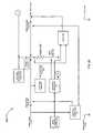
- FIG. 1illustrates a fluid warmer assembly 100 according to a first embodiment of the present invention.
- a fluid warmer 105has a fluid warmer cover 101 and a fluid warmer cover 103 .
- the arrows above the fluid warmer cover 101 and the fluid warmer cover 103show the respective bidirectional capability of movement.
- the fluid warmer cover 101 and the fluid warmer cover 103include a switch (not shown) that generates a fluid warmer cover closure signal 244 , described below, indicating whether the fluid warmer covers 101 , 103 are open or closed.
- a unitary housingincludes the fluid warmer 105 , monitoring and control electronics, and the rechargeable cells.
- the fluid warmer 105is disposed on a fluid warmer heating and control circuit 107 , which includes a group of rechargeable Lithium Polymer cells, namely, LiPo cells 110 , 112 , 114 , and 116 .
- the fluid warmer assembly 100has a removable cartridge 105 a to which a fluid line is attached and through which fluid is caused to flow.
- the cartridgeis typically for a single use and is disposed of after use with a patient.
- the fluid warmer assembly 100is typically usable for a period of time that the battery pack is capable of being recharged.
- a person having an ordinary skill in the artwould appreciate that there could be several variations to a structural relationship between the various components of the fluid warmer assembly 100 described above.
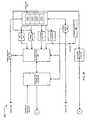
- FIGS. 2A and 2Bdescribe a fluid warmer heating and control circuit 200 according to the first embodiment of the present invention.
- FIGS. 2A and 2Bconnect at points A, B, pack(+) 240 and pack( ⁇ ) 242 .
- the fluid warmer heating and control circuit 200is capable of sensing a hazardous condition inside one or more individual cells, such as LiPo cell 210 , of battery pack 262 . Further, the fluid warmer heating and control circuit 200 permits a magnetic or other isolating coupling of power from a charger 232 to Pack(+) 240 .
- the fluid warmer heating and control circuit 200has a novel structure that does not permit a conduction of electric power from the battery pack 262 through the charger 232 by including a battery discharge switch 230 . That is, electric power from the battery pack 262 to a load does not pass through the charging circuit.
- FIG. 2Ashows that external power is connected through terminals labeled as external power(+) 202 and external power( ⁇ ) 206 .
- a power path controller logic 221akin to steering logic, controls two switches, namely, an external power switch 208 and the battery discharge switch 230 such that based on a need of the fluid warmer assembly 100 or of the battery pack 262 , power may be directed from external power or the battery pack 262 .
- External power(+) 202is also connected to a low voltage power supply 220 which delivers power to all circuits of the fluid warmer assembly 100 except a heater 226 .
- the heater 226includes a heating element, adapted to heat a fluid to be administered to a living body in an efficient manner.
- the heater 226is controlled by a heater control switch 228 operated by a fluid warmer microcontroller 222 .
- the heater 226is powered via a thermal fuse 224 connected to a fluid warmer overtemperature protection circuit 218 and to a second order battery protection circuit 252 shown on FIG. 2B .
- the fluid warmer overtemperature protection circuit 218electrically heats and melts the thermal fuse 224 to prevent an overheating condition.
- the second order battery protection circuit 252independent of other protection measures, has been included.
- the second order battery protection circuit 252electrically heats and melts the thermal fuse 224 to prevent a furtherance of the potentially damaging condition.
- a common damaging conditionis an excessive voltage across the components of the battery pack 262 , namely, LiPo cells 210 , 212 , 214 , and 216 shown on FIG. 2B .
- the second order battery protection circuit 252is shown connected to the voltage sensor 256 , other sensor(s) may also be connected to the second order battery protection circuit 252 .
- the fluid warmer microcontroller 222may operate the heater control switch 228 based on a range of conditions stemming from personal safety and circuit operation considerations.
- a spread spectrum oscillator 204is included in the fluid warmer heating and control circuit 200 for at least two purposes.
- a first purposeis to provide for an improved electromagnetic compatibility (EMC) performance.
- EMCelectromagnetic compatibility
- a second purposeis to facilitate, via the fluid warmer microcontroller 222 , a pulse width modulation of the charger 232 to control the output voltage or regulate the current of the charger 232 .
- the charger 232is connected to the battery pack 262 via pack(+) 240 .
- suitable circuitry included either in the spread spectrum oscillator 204 or the charger 232may permit a direct connection between the spread spectrum oscillator 204 and the charger 232 for controlling the output voltage or regulating the current of the charger 232 .
- charger 232is connected to battery condition indicator and controller 248 described below.
- FIG. 2Balso illustrates some additional monitoring and control blocks to facilitate charging and discharging of the battery pack 262 .
- a battery condition indicator and controller 248may interface with, as shown in FIG. 2B , a first order battery protection circuit 250 , a current sensor 264 , a fluid warmer cover closure signal 244 , and a fluid warmer microcontroller 222 .
- the battery condition indicator and controllerhas an electromagnetic interface.
- the electromagnetic interfaceis an electrical interface.
- the electromagnetic interfaceis an optical interface.
- the battery condition indicator and controller 248is connected to a first order battery protection circuit 250 .
- the battery condition indicator and controller 248 together with the first order battery protection circuit 250provide a first-level protection to the LiPo cells, indicate the battery capacity, charge the LiPo cells in a balanced manner, facilitate “sleep” or “wake”-style activation of the LiPo cells, and communicate with external circuits as needed.
- the operation of the battery condition indicator and controller 248is activated when a fluid warmer cover closure signal 244 is received. That is, the fluid warmer cover closure signal 244 is generated when the fluid warmer covers 101 , 103 operate as shown on FIG. 1 . As an example, heating of a fluid in fluid warmer 105 begins when the fluid warmer covers 101 , 103 are closed.
- the first order battery protection circuit 250accepts inputs from several sensors to operate a battery disconnect switch 246 . These sensors are: voltage sensor 256 , temperature sensors 258 and 260 , current sensor 264 , and strain/pressure sensor 266 . These sensors may be connected to one or more of the LiPo cells 210 , 212 , 214 , and 216 . Though only four LiPo cells 210 , 212 , 214 , and 216 are shown, more or fewer LiPo cells may be employed based on a given application by making simple changes in the fluid warmer heating and control circuit 200 appreciated by a person having an ordinary skill in the art.
- the first order battery protection circuit 250also accepts a temperature sensor 258 and a temperature sensor 260 .
- the temperature sensor 258 and the temperature sensor 260may be located at different points on the battery pack 262 to provide a better monitoring, in a distributed manner, of the overall temperature of the battery pack 262 .
- additional temperature sensorsmay be provided, for example, to monitor an ambient temperature or a body temperature.
- the current sensor 264is also connected to the battery condition indicator and controller 248 to permit a control of the first order battery protection circuit 250 and facilitate the battery condition indicator and controller 248 to function as a “battery gas gauge.” It may also be noted that FIGS. 2A and 2B show the fluid warmer microcontroller 222 and the battery condition indicator and controller 248 as separate blocks but these two may be combined in a single controller.
- the first order battery protection circuit 250is connected to a cell balance circuit 254 .
- the cell balance circuit 254block monitors various parameters, such as charging/discharging current and terminal voltage. Cell balancing is accomplished by shunting current around one or more of the LiPo cells 210 , 212 , 214 , and 216 in an intelligent manner. That is, current is shunted around a cell which has a higher voltage to an adjacent cell during charging.
- the first order battery protection circuit 250is also connected to a strain/pressure sensor 266 via a diode 268 at a point where the temperature sensor 260 is connected.
- the diode 286pulls the temperature sensor 260 low.
- the strain/pressure sensor 266is attached to the battery pack 262 in such a manner that the strain/pressure sensor 266 detects a change in a stress or a strain or a pressure relevant to the battery pack 262 or any of the constituent LiPo cells, such as the LiPo cells 210 , 212 , 214 , and 216 .
- An example of change in dimensionis a swelling or expansion of an individual cell or the battery pack 262 .
- the first order battery protection circuit 250operates in response to the signal of the strain/pressure sensor 266 , to generate suitable alarms(s) and disconnects the batteries via switch 246 .
- the fluid warmer heating and control circuit 200 shown in FIGS. 2A and 2Bconditions external power to make it usable by the low voltage supply 220 , performs pulse width modulation for an intelligent performance of the charger 232 , improves the EMC performance, monitors the battery pack 262 , via several sensors, for a safe operation, includes a back-up battery protection and a fluid warmer overtemperature protection via the thermal fuse 224 . These functions are performed while also sensing the dimensions of the LiPo cells, or the battery pack 262 , for a potential structural failure and not permitting a load current from the battery pack 262 to pass through the charger 232 circuitry.
- FIGS. 2A and 2Bmay be implemented by several commercially available integrated circuits.
- the spread spectrum oscillator 204can be based on LTC6908 of the Linear Technology Corporation.
- a pulse width modulator, to control the charger 232can be implemented by the MCP1630 of the Microchip Technology, Inc.
- the battery condition indicator and controller 248 and the first order battery protection circuit 250can be implemented by the bq20z70 and the bq29330 chipset of Texas Instruments.
- the second order battery protection circuit 252can be implemented by the bq2941x family of Texas Instruments.
- the fluid warmer heating and control circuit 200may be enclosed in a fire- and/or explosion-resistant enclosure ( 150 depicted in FIG. 1 ).
- a fire- and/or explosion-resistant enclosure150 depicted in FIG. 1 .
- Such an enclosurecan contain only the LiPo cells 210 , 212 , 214 , and 216 ( 152 depicted in FIG. 1 ).
- Such enclosuremay be rigid or flexible, and composed of a fire- and/or explosion-resistant material such as Kevlar®.
- Kevlar®a fire- and/or explosion-resistant material
- a commercially available envelope sold under the brand Liposackis also useful for such an enclosure.
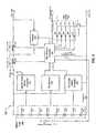
- FIG. 3illustrates a fluid warmer heating and control circuit 300 according to a second embodiment of the present invention.
- eight LiPo cellsnamely, 310 , 312 , 314 , 316 , 310 A, 312 A, 314 A, and 316 A, are connected in series and included in a battery pack 362 .
- Each of the LiPo cellsis connected to a first order battery protection circuit 350 , a second order battery protection circuit 352 and a cell balance circuit 354 .
- the first order battery protection circuit 350 and the cell balance circuit 354are connected to a fluid warmer controller 322 which also receives temperature information from a temperature sensor 358 and from an ambient temperature sensor 372 .
- the fluid warmer controller 322is in communication with a charger 332 .
- the fluid warmer controller 322communicates with a controller of an IV fluid warmer system (not shown) via a data input/output 341 .
- a UART included in the fluid warmer controller 322can be used for data transfer.
- the fluid warmer controller 322is also coupled to an array of LEDs, constituting a battery condition indicator 370 , which indicates battery charge and also a warning of a hazardous condition.
- the battery condition indicator 370may include a display and an annunciator 371 .
- a push-to-test switch 374is provided for actuation of the battery condition indicator 370 .
- the LiPo cells 310 , 312 , 314 , 316 , 310 A, 312 A, 314 A, and 316 Aare connected via a current sensor 364 to the negative output terminal labeled Pack( ⁇ ) 342 .
- the positive output of the stackis connected via a thermal fuse 324 and a pair of MOSFET P 380 and MOSFET P 382 to the positive output terminal labeled Pack (+) 340 .
- the reference numerals 376 and 378indicate the body diodes inherent with the structure of the respective MOSFET P 380 and MOSFET P 382 .
- the charge and discharge states of the LiPo cells 310 , 312 , 314 , 316 , 310 A, 312 A, 314 A, and 316 Aare continuously monitored by the first order battery protection circuit 350 and the second order battery protection circuit 352 and the charge status is provided to the fluid warmer controller 322 .
- the fluid warmer controller 322provides control signals to the cell balance circuit 354 operative to adjust the charging and discharging current to LiPo cells 310 , 312 , 314 , 316 , 310 A, 312 A, 314 A, and 316 A within a safe operating range.
- the fluid warmer controller 322in response to inputs from the first order battery protection circuit 350 and the second order battery protection circuit 352 and/or cell balance circuit 354 and/or from temperature sensor 358 and ambient temperature sensor 372 , causes one or both of MOSFET P 380 and MOSFET P 382 to turn off and thereby shut off the supply of current from the LiPo cells 310 , 312 , 314 , 316 , 310 A, 312 A, 314 A, and 316 A.
- the second order battery protection circuit 352is operative to monitor charge and discharge states of the LiPo cells 310 , 312 , 314 , 316 , 310 A, 312 A, 314 A, and 316 A and in the event of a fault condition provide an output current to melt the thermal fuse 324 to disconnect the LiPo cells 310 , 312 , 314 , 316 , 310 A, 312 A, 314 A, and 316 A before a dangerous condition can occur.
- the charger 332is internal to the fluid warmer assembly 100 of FIG. 1 and eliminates a need for a separate or external charger. In addition, the charger 332 can be operative while the fluid warmer assembly 100 is in use if the fluid warmer assembly 100 is connected to an external charging power source. DC power can be provided to the fluid warmer assembly 100 for operating the charger 332 .
- the fluid warmer controller 322provides an identification information via the data input/output 341 to the fluid warmer assembly 100 such that the fluid warmer assembly 100 recognizes an appropriate power source for powering the fluid warmer assembly 100 .
- FIG. 4illustrates a charger circuit 432 according to the second embodiment of the present invention. Though FIG. 4 shows only one LiPo cell 410 , there could be more such LiPo cells based on a specific application.
- the charger circuit 432directs a discharge load current on a path separate from a path of charging current.
- a switch including MOSFET P 480 and MOSFET P 482connects the LiPo cell 410 to pack(+) 440 , via a thermal fuse 424 , away from the charging circuitry of charger circuit 432 .
- a step up conversionis provided by MOSFET N 484 , MOSFET N 486 , inductor 488 and diode 496 .
- the step up conversionis accomplished under the fluid warmer controller 322 management by holding MOSFET N 484 on and pulsing MOSFET N 486 . While MOSFET N 486 is on, current rises in inductor 488 , and when MOSFET N 486 turns off, the voltage across inductor 488 reverses polarity and discharges from the pack+ 440 terminal through diode 496 into the battery.
- MOSFET N 484 and MOSFET N 486turn off, the voltage across inductor 488 reverses polarity and discharges through diode 496 into the LiPo cell 410 and from the LiPo cell 410 through diode 494 .
- the diodes 494 and 496may be replaced with an active switch, such as a MOSFET, for a higher efficiency.
- Charge currentis controlled by measuring the voltage drop across a current sensor 464 and varying the duty cycle of MOSFET N 484 and MOSFET N 486 .
- the reference numerals 476 , 478 , 490 , and 492indicate the body diodes inherent with the structure of the respective MOSFET P 480 , MOSFET P 482 , MOSFET N 484 , and MOSFET N 486 .
- the embodiment described aboveemploys a buck-boost converter.
- a SEPIC converterSingle-ended Primary Inductance Converter
- the second order battery protection circuit 352can interrupt power using the thermal fuse 424 in the event of a major failure such as failure of the MOSFET P 480 or MOSFET P 482 , or of the first order battery protection circuit 350 .
- the fluid warmer assembly 100can also be used for heating other liquids or substances with suitable modifications or enhancements.
- the inventionis not limited to heating IV or other fluids, but is applicable to powering other electrical devices and equipment including other medical devices and equipment.
Landscapes
- Engineering & Computer Science (AREA)
- Power Engineering (AREA)
- Chemical & Material Sciences (AREA)
- Life Sciences & Earth Sciences (AREA)
- Chemical Kinetics & Catalysis (AREA)
- General Chemical & Material Sciences (AREA)
- Electrochemistry (AREA)
- Manufacturing & Machinery (AREA)
- Sustainable Development (AREA)
- Sustainable Energy (AREA)
- Transportation (AREA)
- Mechanical Engineering (AREA)
- Health & Medical Sciences (AREA)
- Dispersion Chemistry (AREA)
- Hematology (AREA)
- General Physics & Mathematics (AREA)
- Inorganic Chemistry (AREA)
- Physics & Mathematics (AREA)
- Vascular Medicine (AREA)
- Anesthesiology (AREA)
- Biomedical Technology (AREA)
- Heart & Thoracic Surgery (AREA)
- Condensed Matter Physics & Semiconductors (AREA)
- Animal Behavior & Ethology (AREA)
- General Health & Medical Sciences (AREA)
- Public Health (AREA)
- Veterinary Medicine (AREA)
- Battery Mounting, Suspending (AREA)
- Secondary Cells (AREA)
- Charge And Discharge Circuits For Batteries Or The Like (AREA)
- Microelectronics & Electronic Packaging (AREA)
Abstract
Description
Claims (21)
Priority Applications (3)
| Application Number | Priority Date | Filing Date | Title |
|---|---|---|---|
| US11/593,456US7741815B2 (en) | 2005-11-07 | 2006-11-06 | Lithium polymer battery powered intravenous fluid warmer |
| US12/820,094US7956583B2 (en) | 2005-11-07 | 2010-06-21 | Lithium polymer battery powered intravenous fluid warmer |
| US13/155,032US8796997B2 (en) | 2005-11-07 | 2011-06-07 | Lithium polymer battery powered intravenous fluid warmer |
Applications Claiming Priority (2)
| Application Number | Priority Date | Filing Date | Title |
|---|---|---|---|
| US73410805P | 2005-11-07 | 2005-11-07 | |
| US11/593,456US7741815B2 (en) | 2005-11-07 | 2006-11-06 | Lithium polymer battery powered intravenous fluid warmer |
Related Child Applications (1)
| Application Number | Title | Priority Date | Filing Date |
|---|---|---|---|
| US12/820,094ContinuationUS7956583B2 (en) | 2005-11-07 | 2010-06-21 | Lithium polymer battery powered intravenous fluid warmer |
Publications (2)
| Publication Number | Publication Date |
|---|---|
| US20070105010A1 US20070105010A1 (en) | 2007-05-10 |
| US7741815B2true US7741815B2 (en) | 2010-06-22 |
Family
ID=38023853
Family Applications (3)
| Application Number | Title | Priority Date | Filing Date |
|---|---|---|---|
| US11/593,456Expired - Fee RelatedUS7741815B2 (en) | 2005-11-07 | 2006-11-06 | Lithium polymer battery powered intravenous fluid warmer |
| US12/820,094Expired - Fee RelatedUS7956583B2 (en) | 2005-11-07 | 2010-06-21 | Lithium polymer battery powered intravenous fluid warmer |
| US13/155,032Expired - Fee RelatedUS8796997B2 (en) | 2005-11-07 | 2011-06-07 | Lithium polymer battery powered intravenous fluid warmer |
Family Applications After (2)
| Application Number | Title | Priority Date | Filing Date |
|---|---|---|---|
| US12/820,094Expired - Fee RelatedUS7956583B2 (en) | 2005-11-07 | 2010-06-21 | Lithium polymer battery powered intravenous fluid warmer |
| US13/155,032Expired - Fee RelatedUS8796997B2 (en) | 2005-11-07 | 2011-06-07 | Lithium polymer battery powered intravenous fluid warmer |
Country Status (7)
| Country | Link |
|---|---|
| US (3) | US7741815B2 (en) |
| EP (2) | EP2993726B1 (en) |
| AU (1) | AU2006311869B2 (en) |
| BR (1) | BRPI0618336A2 (en) |
| CA (2) | CA2843561C (en) |
| NZ (1) | NZ568768A (en) |
| WO (1) | WO2007056202A2 (en) |
Cited By (14)
| Publication number | Priority date | Publication date | Assignee | Title |
|---|---|---|---|---|
| US20080260364A1 (en)* | 2006-12-12 | 2008-10-23 | Vandrak Brian S | Forced Air Heater Including On-Board Source of Electric Energy |
| US20090008374A1 (en)* | 2007-07-06 | 2009-01-08 | Illinois Tool Works Inc. | Portable generator and battery charger verification control method and system |
| US20110202034A1 (en)* | 2010-02-17 | 2011-08-18 | Estill Medical Technologies, Inc. | Modular medical fluid heating apparatus |
| US20110265779A1 (en)* | 2006-12-12 | 2011-11-03 | Enerco Group, Inc. | Forced Air Heater Including On-Board Source of Electric energy |
| US8421465B2 (en) | 2009-12-02 | 2013-04-16 | Covidien Lp | Method and apparatus for indicating battery cell status on a battery pack assembly used during mechanical ventilation |
| US8690842B2 (en) | 2010-09-27 | 2014-04-08 | Estill Medical Technologies, Inc. | Electrical power source for an intravenous fluid heating system |
| US8776790B2 (en) | 2009-07-16 | 2014-07-15 | Covidien Lp | Wireless, gas flow-powered sensor system for a breathing assistance system |
| US8902568B2 (en) | 2006-09-27 | 2014-12-02 | Covidien Lp | Power supply interface system for a breathing assistance system |
| US9269990B2 (en) | 2008-09-30 | 2016-02-23 | Covidien Lp | Battery management for a breathing assistance system |
| US20160301224A1 (en)* | 2015-04-10 | 2016-10-13 | Samsung Sdi Co., Ltd. | Battery protection circuit |
| USD775345S1 (en) | 2015-04-10 | 2016-12-27 | Covidien Lp | Ventilator console |
| US10596652B2 (en) | 2014-11-13 | 2020-03-24 | Illinois Tool Works Inc. | Systems and methods for fuel level monitoring in an engine-driven generator |
| US10780258B2 (en) | 2015-03-10 | 2020-09-22 | Life Warmer Inc. | Thermic infusion system |
| US11707580B2 (en) | 2017-09-08 | 2023-07-25 | Life Warmer Inc. | Thermic infusion system dry tube detector |
Families Citing this family (42)
| Publication number | Priority date | Publication date | Assignee | Title |
|---|---|---|---|---|
| US20090123814A1 (en)* | 2007-10-09 | 2009-05-14 | Mason Cabot | Power source and method of managing a power source |
| WO2009048974A1 (en)* | 2007-10-09 | 2009-04-16 | Hum Cycles, Inc. | Power source and method of managing a power source |
| US9050098B2 (en) | 2007-11-28 | 2015-06-09 | Covidien Ag | Cordless medical cauterization and cutting device |
| US8758342B2 (en)* | 2007-11-28 | 2014-06-24 | Covidien Ag | Cordless power-assisted medical cauterization and cutting device |
| US10923776B2 (en)* | 2007-12-31 | 2021-02-16 | Apple Inc. | Systems and methods for monitoring and responding to forces influencing a battery |
| JP5065958B2 (en)* | 2008-03-26 | 2012-11-07 | パナソニック株式会社 | Battery pack |
| US20090261785A1 (en)* | 2008-03-27 | 2009-10-22 | Mason Cabot | Method for managing a modular power source |
| JP5219587B2 (en)* | 2008-03-31 | 2013-06-26 | 三洋電機株式会社 | Laminated battery and battery module including the laminated battery |
| US20100136405A1 (en)* | 2008-04-02 | 2010-06-03 | Karl Johnson | Battery pack with optimized mechanical, electrical, and thermal management |
| WO2009124222A2 (en)* | 2008-04-02 | 2009-10-08 | Mission Motor Company | System and method of integrated thermal management for a multi-cell battery pack |
| JP4687743B2 (en)* | 2008-05-02 | 2011-05-25 | ソニー株式会社 | Battery pack and control method |
| US9782217B2 (en) | 2008-11-13 | 2017-10-10 | Covidien Ag | Radio frequency generator and method for a cordless medical cauterization and cutting device |
| US8316976B2 (en)* | 2008-11-20 | 2012-11-27 | Mission Motor Company | Frame for a ride-on vehicle having a plurality of battery packs |
| DE102009003180A1 (en)* | 2009-05-18 | 2010-11-25 | Robert Bosch Gmbh | Method and circuit arrangement for heating an electrical energy store |
| CN102222941B (en)* | 2010-04-13 | 2013-09-18 | 登丰微电子股份有限公司 | Battery voltage balancing device and battery charging device |
| CA2795946C (en)* | 2010-04-14 | 2020-02-25 | Enerco Group, Inc. | Forced air heater including on-board source of electric energy |
| US8312954B2 (en) | 2010-04-22 | 2012-11-20 | Mission Motor Company | Frame for a two wheeled electric vehicle |
| EP2616122A4 (en) | 2010-09-15 | 2014-07-02 | Gen Hospital Corp | METHOD AND APPARATUS FOR HEATING INTRAVENOUS FLUIDS |
| US9608297B2 (en)* | 2011-11-16 | 2017-03-28 | Datang Nxp Semiconductors Co., Ltd. | In-cell battery management device |
| US9276421B2 (en)* | 2012-10-31 | 2016-03-01 | Motorola Solutions, Inc. | Portable rechargeable battery pack and external adapter for same |
| US9097775B2 (en) | 2012-11-13 | 2015-08-04 | Motorola Solutions, Inc. | Apparatus and method for discharging a battery and determining a condition of the battery |
| CN102969700A (en)* | 2012-11-19 | 2013-03-13 | 雷星亮 | Battery protector and battery device |
| DE102012222721A1 (en) | 2012-12-11 | 2014-06-12 | Robert Bosch Gmbh | Battery management system and battery system |
| DE102012222720A1 (en)* | 2012-12-11 | 2014-06-12 | Robert Bosch Gmbh | Battery management system and battery system |
| US9209497B2 (en) | 2012-12-17 | 2015-12-08 | Infineon Technologies Ag | Sensor module and battery elements |
| US9337667B2 (en) | 2013-02-28 | 2016-05-10 | Motorola Solutions, Inc. | External adapter for battery pack used to power a portable device |
| DE102014200329A1 (en)* | 2014-01-10 | 2015-07-16 | Robert Bosch Gmbh | Electrochemical energy storage and method for balancing |
| WO2015147977A1 (en)* | 2014-03-24 | 2015-10-01 | General Electric Company | Battery cell health monitoring using eddy currents |
| CN104548285A (en)* | 2014-12-03 | 2015-04-29 | 广西大学 | Infusion heating instrument |
| CN104617346A (en)* | 2014-12-25 | 2015-05-13 | 山东精工电子科技有限公司 | Method for measuring liquid injection amount of polymer lithium-ion battery |
| JP6660696B2 (en) | 2015-09-17 | 2020-03-11 | 三菱重工業株式会社 | Explosion-proof equipment |
| US20180309307A1 (en)* | 2015-10-07 | 2018-10-25 | Revision Military S.à.r.I. | Low temperature battery systems and methods |
| CN105893650A (en)* | 2015-12-30 | 2016-08-24 | 丹东思诚科技有限公司 | Simulation software for equalization and protection of batteries which are connected in series |
| CN108604806B (en)* | 2016-02-17 | 2021-09-21 | 丰田自动车欧洲公司 | System and method for battery charge control |
| CN107571764A (en)* | 2017-09-30 | 2018-01-12 | 珠海市领创智能物联网研究院有限公司 | A kind of electric car based on Internet of Things fills breaker device automatically |
| US20190222038A1 (en)* | 2018-01-12 | 2019-07-18 | Zhangsheng CHEN | Portable Emergency Energy-Storage System with Intelligent Protection |
| WO2019167786A1 (en)* | 2018-03-01 | 2019-09-06 | 株式会社村田製作所 | Assembled battery |
| JP6738857B2 (en)* | 2018-06-06 | 2020-08-12 | 矢崎総業株式会社 | Sensor protector |
| CN109621100A (en)* | 2018-12-17 | 2019-04-16 | 桂林理工大学 | A kind of optical energy power drop heating device |
| CN116437882A (en)* | 2020-09-10 | 2023-07-14 | 约翰·J·桑多瓦尔 | Medical fluid warming sheath for IV fluid bag and method for warming IV fluid bag |
| CN112721729B (en)* | 2020-12-29 | 2023-03-03 | 联合汽车电子有限公司 | Control method and control system of battery |
| US11936180B2 (en)* | 2022-06-29 | 2024-03-19 | Google Llc | Overvoltage protection for data communication path |
Citations (24)
| Publication number | Priority date | Publication date | Assignee | Title |
|---|---|---|---|---|
| US4314143A (en)* | 1979-06-29 | 1982-02-02 | Baxter Travenol Laboratories, Inc. | Blood warming apparatus with digital display and monitoring circuit |
| US4709202A (en)* | 1982-06-07 | 1987-11-24 | Norand Corporation | Battery powered system |
| US4845419A (en)* | 1985-11-12 | 1989-07-04 | Norand Corporation | Automatic control means providing a low-power responsive signal, particularly for initiating data preservation operation |
| US5408577A (en)* | 1992-03-16 | 1995-04-18 | Sonne Medical | Method and heater apparatus with protective fuse for medical applications |
| US5568039A (en)* | 1994-12-16 | 1996-10-22 | Motorola, Inc. | Apparatus and method of providing an initiation voltage to a rechargeable battery system |
| US5583415A (en)* | 1994-12-27 | 1996-12-10 | Motorola, Inc. | Apparatus for simulating high battery temperature for rechargeble battery systems |
| US5680027A (en)* | 1992-10-23 | 1997-10-21 | Sony Corporation | Battery pack including internal capacity monitor for monitoring groups of battery cells |
| US5680031A (en) | 1996-03-26 | 1997-10-21 | Norvik Traction Inc. | Method and apparatus for charging batteries |
| US5767659A (en)* | 1991-10-30 | 1998-06-16 | Texas Instruments Incorporated | Batteries and battery systems |
| WO1999039400A1 (en) | 1998-01-31 | 1999-08-05 | Oglesbee John W | Overcharge protection device and methods for lithium-based rechargeable batteries |
| US6142974A (en) | 1998-09-18 | 2000-11-07 | Estill Medical Technologies, Incorporated | Portable I.V. fluid warming system |
| US6175688B1 (en)* | 1998-07-10 | 2001-01-16 | Belmont Instrument Corporation | Wearable intravenous fluid heater |
| US6229957B1 (en)* | 1999-05-14 | 2001-05-08 | Joseph Baker | Physiological fluid warming process and apparatus |
| US6271645B1 (en)* | 2000-02-11 | 2001-08-07 | Delphi Technologies, Inc. | Method for balancing battery pack energy levels |
| US6495992B1 (en)* | 1996-03-26 | 2002-12-17 | Norvik Traction Inc. | Method and apparatus for charging batteries utilizing heterogeneous reaction kinetics |
| US6534951B2 (en) | 2000-12-20 | 2003-03-18 | Nec Corporation | Battery charger |
| US6641556B1 (en) | 1999-07-06 | 2003-11-04 | Respiratory Support Products, Inc. | Intravenous fluid heating system |
| US6664000B1 (en) | 1999-09-30 | 2003-12-16 | Nec Mobile Energy Corporation | Battery pack |
| US20040096732A1 (en) | 2002-11-15 | 2004-05-20 | Shin Jeong-Soon | Safety apparatus for secondary battery and secondary battery having the same |
| US6747561B1 (en)* | 2000-06-20 | 2004-06-08 | Med-Datanet, Llc | Bodily worn device for digital storage and retrieval of medical records and personal identification |
| US20040170409A1 (en)* | 2001-03-12 | 2004-09-02 | Faries Durward I. | Method and apparatus for controlling temperature of infused liquids |
| WO2005009500A2 (en) | 2003-07-09 | 2005-02-03 | Enginivity Llc | Medical fluid warming system |
| US20050161588A1 (en) | 2004-01-26 | 2005-07-28 | Kominsky Richard A. | Method and system for spread spectrum gating |
| US7514903B2 (en)* | 2004-09-24 | 2009-04-07 | Samsung Sdi Co., Ltd. | Battery pack |
Family Cites Families (12)
| Publication number | Priority date | Publication date | Assignee | Title |
|---|---|---|---|---|
| US4464563A (en)* | 1981-08-28 | 1984-08-07 | Jewett Warren R | Intravenous fluid warmer |
| US5108372A (en)* | 1990-12-12 | 1992-04-28 | Houston Advanced Research Center | Intravenous fluid temperature regulation method and apparatus |
| US5796238A (en)* | 1992-10-13 | 1998-08-18 | Sony Corporation | Battery pack |
| EP1032955A4 (en)* | 1998-07-27 | 2002-08-07 | Gnb Technologies | Apparatus and method for carrying out diagnostic tests on batteries and for rapidly charging batteries |
| US6516227B1 (en)* | 1999-07-27 | 2003-02-04 | Advanced Bionics Corporation | Rechargeable spinal cord stimulator system |
| JP2001280704A (en)* | 2000-03-31 | 2001-10-10 | Toto Ltd | Fluid heater and local cleaning device |
| JP3699381B2 (en)* | 2001-10-02 | 2005-09-28 | ソニーケミカル株式会社 | Secondary battery with protection circuit |
| EP1333581B1 (en)* | 2002-01-30 | 2015-04-08 | Infineon Technologies AG | Clock signal generator |
| CA2516815A1 (en)* | 2003-04-23 | 2004-11-18 | Powertron Eng'g Co., Ltd | Diagnosis for expected life of emergency power apparatus |
| JP2005011757A (en)* | 2003-06-20 | 2005-01-13 | Toyota Motor Corp | Secondary battery temperature abnormality detection device and abnormality detection method |
| US7352087B2 (en)* | 2003-12-31 | 2008-04-01 | Intel Corporation | Power system configuration |
| US7615965B2 (en)* | 2004-05-14 | 2009-11-10 | O2Micro International Limited | Power management system |
- 2006
- 2006-11-06EPEP15189937.4Apatent/EP2993726B1/ennot_activeNot-in-force
- 2006-11-06WOPCT/US2006/043069patent/WO2007056202A2/enactiveApplication Filing
- 2006-11-06CACA2843561Apatent/CA2843561C/ennot_activeExpired - Fee Related
- 2006-11-06CACA2628431Apatent/CA2628431C/ennot_activeExpired - Fee Related
- 2006-11-06USUS11/593,456patent/US7741815B2/ennot_activeExpired - Fee Related
- 2006-11-06NZNZ568768Apatent/NZ568768A/ennot_activeIP Right Cessation
- 2006-11-06EPEP06827498.4Apatent/EP1952478B1/ennot_activeNot-in-force
- 2006-11-06BRBRPI0618336-0Apatent/BRPI0618336A2/ennot_activeIP Right Cessation
- 2006-11-06AUAU2006311869Apatent/AU2006311869B2/ennot_activeCeased
- 2010
- 2010-06-21USUS12/820,094patent/US7956583B2/ennot_activeExpired - Fee Related
- 2011
- 2011-06-07USUS13/155,032patent/US8796997B2/ennot_activeExpired - Fee Related
Patent Citations (29)
| Publication number | Priority date | Publication date | Assignee | Title |
|---|---|---|---|---|
| US4314143A (en)* | 1979-06-29 | 1982-02-02 | Baxter Travenol Laboratories, Inc. | Blood warming apparatus with digital display and monitoring circuit |
| US4709202A (en)* | 1982-06-07 | 1987-11-24 | Norand Corporation | Battery powered system |
| US4845419A (en)* | 1985-11-12 | 1989-07-04 | Norand Corporation | Automatic control means providing a low-power responsive signal, particularly for initiating data preservation operation |
| US5767659A (en)* | 1991-10-30 | 1998-06-16 | Texas Instruments Incorporated | Batteries and battery systems |
| US5408577A (en)* | 1992-03-16 | 1995-04-18 | Sonne Medical | Method and heater apparatus with protective fuse for medical applications |
| US5680027A (en)* | 1992-10-23 | 1997-10-21 | Sony Corporation | Battery pack including internal capacity monitor for monitoring groups of battery cells |
| US5568039A (en)* | 1994-12-16 | 1996-10-22 | Motorola, Inc. | Apparatus and method of providing an initiation voltage to a rechargeable battery system |
| US5583415A (en)* | 1994-12-27 | 1996-12-10 | Motorola, Inc. | Apparatus for simulating high battery temperature for rechargeble battery systems |
| US5680031A (en) | 1996-03-26 | 1997-10-21 | Norvik Traction Inc. | Method and apparatus for charging batteries |
| US6495992B1 (en)* | 1996-03-26 | 2002-12-17 | Norvik Traction Inc. | Method and apparatus for charging batteries utilizing heterogeneous reaction kinetics |
| WO1999039400A1 (en) | 1998-01-31 | 1999-08-05 | Oglesbee John W | Overcharge protection device and methods for lithium-based rechargeable batteries |
| US6175688B1 (en)* | 1998-07-10 | 2001-01-16 | Belmont Instrument Corporation | Wearable intravenous fluid heater |
| US6236809B1 (en)* | 1998-07-10 | 2001-05-22 | Belmont Instrument Corporation | Wearable intravenous fluid heater |
| US20010011585A1 (en)* | 1998-07-10 | 2001-08-09 | David Cassidy | Heat exchanger useable in wearable fluid heater |
| US6480257B2 (en)* | 1998-07-10 | 2002-11-12 | Belmont Instrument Corporation | Heat exchanger useable in wearable fluid heater |
| US6142974A (en) | 1998-09-18 | 2000-11-07 | Estill Medical Technologies, Incorporated | Portable I.V. fluid warming system |
| US6229957B1 (en)* | 1999-05-14 | 2001-05-08 | Joseph Baker | Physiological fluid warming process and apparatus |
| US6641556B1 (en) | 1999-07-06 | 2003-11-04 | Respiratory Support Products, Inc. | Intravenous fluid heating system |
| US6664000B1 (en) | 1999-09-30 | 2003-12-16 | Nec Mobile Energy Corporation | Battery pack |
| US6271645B1 (en)* | 2000-02-11 | 2001-08-07 | Delphi Technologies, Inc. | Method for balancing battery pack energy levels |
| US6747561B1 (en)* | 2000-06-20 | 2004-06-08 | Med-Datanet, Llc | Bodily worn device for digital storage and retrieval of medical records and personal identification |
| US20040140898A1 (en)* | 2000-06-20 | 2004-07-22 | Reeves William Francis | Bodily worn device for digital storage and retrieval of emergency medical records and personal identification |
| US6534951B2 (en) | 2000-12-20 | 2003-03-18 | Nec Corporation | Battery charger |
| US20040170409A1 (en)* | 2001-03-12 | 2004-09-02 | Faries Durward I. | Method and apparatus for controlling temperature of infused liquids |
| US7031602B2 (en)* | 2001-03-12 | 2006-04-18 | Patented Medical Solutions, Llc | Method and apparatus for controlling temperature of infused liquids |
| US20040096732A1 (en) | 2002-11-15 | 2004-05-20 | Shin Jeong-Soon | Safety apparatus for secondary battery and secondary battery having the same |
| WO2005009500A2 (en) | 2003-07-09 | 2005-02-03 | Enginivity Llc | Medical fluid warming system |
| US20050161588A1 (en) | 2004-01-26 | 2005-07-28 | Kominsky Richard A. | Method and system for spread spectrum gating |
| US7514903B2 (en)* | 2004-09-24 | 2009-04-07 | Samsung Sdi Co., Ltd. | Battery pack |
Non-Patent Citations (1)
| Title |
|---|
| Dallas Semiconductor DS1086 Spread-Spectrum EconOscillator Data sheet, Sep. 2003.* |
Cited By (25)
| Publication number | Priority date | Publication date | Assignee | Title |
|---|---|---|---|---|
| US8902568B2 (en) | 2006-09-27 | 2014-12-02 | Covidien Lp | Power supply interface system for a breathing assistance system |
| US9927144B2 (en) | 2006-12-12 | 2018-03-27 | Enerco Group, Inc. | Forced air heater including multiple on-board sources of electric energy |
| US8494350B2 (en)* | 2006-12-12 | 2013-07-23 | Enerco Group, Inc. | Forced air heater including on-board source of electric energy |
| US20110265779A1 (en)* | 2006-12-12 | 2011-11-03 | Enerco Group, Inc. | Forced Air Heater Including On-Board Source of Electric energy |
| US20110268429A1 (en)* | 2006-12-12 | 2011-11-03 | Enerco Group, Inc. | Forced Air Heater Including On-Board Source of Electric Energy |
| US8068724B2 (en)* | 2006-12-12 | 2011-11-29 | Enerco Group, Inc. | Forced air heater including on-board source of electric energy |
| US10495344B2 (en) | 2006-12-12 | 2019-12-03 | Enerco Group, Inc. | Forced air heater including multiple on-board sources of electric energy |
| US8893706B2 (en)* | 2006-12-12 | 2014-11-25 | Enerco Group, Inc. | Forced air heater including on-board source of electric energy |
| US20080260364A1 (en)* | 2006-12-12 | 2008-10-23 | Vandrak Brian S | Forced Air Heater Including On-Board Source of Electric Energy |
| US10576573B2 (en) | 2007-07-06 | 2020-03-03 | Illinois Tool Works Inc. | Portable generator and battery charger verification control method and system |
| US8759714B2 (en)* | 2007-07-06 | 2014-06-24 | Illinois Tool Works Inc. | Portable generator and battery charger verification control method and system |
| US20090008374A1 (en)* | 2007-07-06 | 2009-01-08 | Illinois Tool Works Inc. | Portable generator and battery charger verification control method and system |
| US9269990B2 (en) | 2008-09-30 | 2016-02-23 | Covidien Lp | Battery management for a breathing assistance system |
| US8776790B2 (en) | 2009-07-16 | 2014-07-15 | Covidien Lp | Wireless, gas flow-powered sensor system for a breathing assistance system |
| US8547062B2 (en) | 2009-12-02 | 2013-10-01 | Covidien Lp | Apparatus and system for a battery pack assembly used during mechanical ventilation |
| US9364626B2 (en) | 2009-12-02 | 2016-06-14 | Covidien Lp | Battery pack assembly having a status indicator for use during mechanical ventilation |
| US8421465B2 (en) | 2009-12-02 | 2013-04-16 | Covidien Lp | Method and apparatus for indicating battery cell status on a battery pack assembly used during mechanical ventilation |
| US20110202034A1 (en)* | 2010-02-17 | 2011-08-18 | Estill Medical Technologies, Inc. | Modular medical fluid heating apparatus |
| US8690842B2 (en) | 2010-09-27 | 2014-04-08 | Estill Medical Technologies, Inc. | Electrical power source for an intravenous fluid heating system |
| US10596652B2 (en) | 2014-11-13 | 2020-03-24 | Illinois Tool Works Inc. | Systems and methods for fuel level monitoring in an engine-driven generator |
| US10780258B2 (en) | 2015-03-10 | 2020-09-22 | Life Warmer Inc. | Thermic infusion system |
| US20160301224A1 (en)* | 2015-04-10 | 2016-10-13 | Samsung Sdi Co., Ltd. | Battery protection circuit |
| US10389148B2 (en)* | 2015-04-10 | 2019-08-20 | Samsung Sdi Co., Ltd. | Battery protection circuit employing thermistor sensing of charging switch and discharging switch |
| USD775345S1 (en) | 2015-04-10 | 2016-12-27 | Covidien Lp | Ventilator console |
| US11707580B2 (en) | 2017-09-08 | 2023-07-25 | Life Warmer Inc. | Thermic infusion system dry tube detector |
Also Published As
| Publication number | Publication date |
|---|---|
| CA2843561A1 (en) | 2007-05-18 |
| WO2007056202A2 (en) | 2007-05-18 |
| CA2628431A1 (en) | 2007-05-18 |
| US20110238012A1 (en) | 2011-09-29 |
| AU2006311869B2 (en) | 2011-10-27 |
| EP1952478A2 (en) | 2008-08-06 |
| US20100253288A1 (en) | 2010-10-07 |
| EP2993726A1 (en) | 2016-03-09 |
| WO2007056202A3 (en) | 2007-10-18 |
| CA2628431C (en) | 2014-05-06 |
| US8796997B2 (en) | 2014-08-05 |
| EP2993726B1 (en) | 2017-04-26 |
| EP1952478A4 (en) | 2012-11-28 |
| EP1952478B1 (en) | 2016-01-06 |
| NZ568768A (en) | 2010-05-28 |
| AU2006311869A1 (en) | 2007-05-18 |
| BRPI0618336A2 (en) | 2011-08-23 |
| US7956583B2 (en) | 2011-06-07 |
| US20070105010A1 (en) | 2007-05-10 |
| CA2843561C (en) | 2014-10-28 |
Similar Documents
| Publication | Publication Date | Title |
|---|---|---|
| US7741815B2 (en) | Lithium polymer battery powered intravenous fluid warmer | |
| JP6829734B2 (en) | Systems and methods for automatic detection of battery insertion | |
| JP2020162411A (en) | Battery management system for controlling lithium power cells | |
| EP1410458B1 (en) | Improvements to rechargeable batteries | |
| CN103828180B (en) | Battery management system with MOSFET booster systems | |
| US7825624B2 (en) | Battery-operated power output device | |
| TW201240276A (en) | High voltage battery system for vehicle applications | |
| US20240154412A1 (en) | Portable Jump Starter and Air Compressor Device | |
| US20120220938A1 (en) | Intravenous fluid heater | |
| Mastanamma et al. | EV BMS With Charge Monitor and Fire Detection | |
| US8562562B2 (en) | Intravenous fluid heater | |
| US20250267826A1 (en) | Portable Jump Starter and Air Compressor Device | |
| JPH03285523A (en) | Charger |
Legal Events
| Date | Code | Title | Description |
|---|---|---|---|
| AS | Assignment | Owner name:ENGINIVITY LLC,MASSACHUSETTS Free format text:ASSIGNMENT OF ASSIGNORS INTEREST;ASSIGNOR:CASSIDY, DAVID;REEL/FRAME:018623/0235 Effective date:20061117 Owner name:ENGINIVITY LLC, MASSACHUSETTS Free format text:ASSIGNMENT OF ASSIGNORS INTEREST;ASSIGNOR:CASSIDY, DAVID;REEL/FRAME:018623/0235 Effective date:20061117 | |
| AS | Assignment | Owner name:ENGINIVITY LLC,MASSACHUSETTS Free format text:ASSIGNMENT OF ASSIGNORS INTEREST;ASSIGNOR:ENGINIVITY LLC;REEL/FRAME:019019/0933 Effective date:20070308 Owner name:ENGINIVITY LLC, MASSACHUSETTS Free format text:ASSIGNMENT OF ASSIGNORS INTEREST;ASSIGNOR:ENGINIVITY LLC;REEL/FRAME:019019/0933 Effective date:20070308 | |
| AS | Assignment | Owner name:GENERAL ELECTRIC COMPANY,NEW YORK Free format text:ASSIGNMENT OF ASSIGNORS INTEREST;ASSIGNOR:ENGINIVITY LLC;REEL/FRAME:023870/0934 Effective date:20100119 Owner name:GENERAL ELECTRIC COMPANY, NEW YORK Free format text:ASSIGNMENT OF ASSIGNORS INTEREST;ASSIGNOR:ENGINIVITY LLC;REEL/FRAME:023870/0934 Effective date:20100119 | |
| STCF | Information on status: patent grant | Free format text:PATENTED CASE | |
| AS | Assignment | Owner name:VITAL SIGNS, INC., NEW JERSEY Free format text:ASSIGNMENT OF PATENTS;ASSIGNOR:GENERAL ELECTRIC COMPANY;REEL/FRAME:031536/0862 Effective date:20131028 | |
| AS | Assignment | Owner name:VITAL SIGNS, INC., NEW JERSEY Free format text:UNIT PURCHASE AGREEMENT;ASSIGNOR:ENGINIVITY, LLC;REEL/FRAME:031744/0758 Effective date:20070814 Owner name:VITAL SIGNS, INC., NEW JERSEY Free format text:DISSOLUTION;ASSIGNOR:ENGINIVITY, LLC;REEL/FRAME:031744/0739 Effective date:20111116 | |
| FPAY | Fee payment | Year of fee payment:4 | |
| AS | Assignment | Owner name:CITIZENS BANK, N.A, AS COLLATERAL AGENT, MASSACHUSETTS Free format text:SECURITY AGREEMENT;ASSIGNORS:VYAIRE MEDICAL CAPITAL LLC;VYAIRE MEDICAL CONSUMABLES LLC;VITAL SIGNS, INC.;AND OTHERS;REEL/FRAME:040357/0952 Effective date:20161013 Owner name:CITIZENS BANK, N.A, AS COLLATERAL AGENT, MASSACHUS Free format text:SECURITY AGREEMENT;ASSIGNORS:VYAIRE MEDICAL CAPITAL LLC;VYAIRE MEDICAL CONSUMABLES LLC;VITAL SIGNS, INC.;AND OTHERS;REEL/FRAME:040357/0952 Effective date:20161013 | |
| MAFP | Maintenance fee payment | Free format text:PAYMENT OF MAINTENANCE FEE, 8TH YEAR, LARGE ENTITY (ORIGINAL EVENT CODE: M1552) Year of fee payment:8 | |
| AS | Assignment | Owner name:VITAL SIGNS, INC., ILLINOIS Free format text:RELEASE BY SECURED PARTY;ASSIGNOR:CITIZENS BANK, N.A.;REEL/FRAME:045779/0035 Effective date:20180416 Owner name:VYAIRE MEDICAL CONSUMABLES LLC, ILLINOIS Free format text:RELEASE BY SECURED PARTY;ASSIGNOR:CITIZENS BANK, N.A.;REEL/FRAME:045779/0035 Effective date:20180416 Owner name:CAREFUSION 202, INC., ILLINOIS Free format text:RELEASE BY SECURED PARTY;ASSIGNOR:CITIZENS BANK, N.A.;REEL/FRAME:045779/0035 Effective date:20180416 Owner name:VYAIRE MEDICAL CAPITAL LLC, ILLINOIS Free format text:RELEASE BY SECURED PARTY;ASSIGNOR:CITIZENS BANK, N.A.;REEL/FRAME:045779/0035 Effective date:20180416 | |
| AS | Assignment | Owner name:BANK OF AMERICA, N.A., AS COLLATERAL AGENT, NORTH Free format text:FIRST LIEN SECURITY AGREEMENT;ASSIGNOR:VITAL SIGNS, INC.;REEL/FRAME:045968/0050 Effective date:20180416 Owner name:WILMINGTON TRUST, NATIONAL ASSOCIATION, AS COLLATE Free format text:SECOND LIEN SECURITY AGREEMENT;ASSIGNOR:VITAL SIGNS, INC.;REEL/FRAME:045969/0596 Effective date:20180416 | |
| AS | Assignment | Owner name:WILMINGTON TRUST, NATIONAL ASSOCIATION, MINNESOTA Free format text:SECURITY INTEREST;ASSIGNOR:VITAL SIGNS, INC.;REEL/FRAME:049129/0006 Effective date:20190503 | |
| FEPP | Fee payment procedure | Free format text:MAINTENANCE FEE REMINDER MAILED (ORIGINAL EVENT CODE: REM.); ENTITY STATUS OF PATENT OWNER: LARGE ENTITY | |
| LAPS | Lapse for failure to pay maintenance fees | Free format text:PATENT EXPIRED FOR FAILURE TO PAY MAINTENANCE FEES (ORIGINAL EVENT CODE: EXP.); ENTITY STATUS OF PATENT OWNER: LARGE ENTITY | |
| STCH | Information on status: patent discontinuation | Free format text:PATENT EXPIRED DUE TO NONPAYMENT OF MAINTENANCE FEES UNDER 37 CFR 1.362 | |
| FP | Lapsed due to failure to pay maintenance fee | Effective date:20220622 |