US7740801B2 - System for determination of an analyte in a bodily fluid sample that includes an electroluminescent component - Google Patents
System for determination of an analyte in a bodily fluid sample that includes an electroluminescent componentDownload PDFInfo
- Publication number
- US7740801B2 US7740801B2US11/591,138US59113806AUS7740801B2US 7740801 B2US7740801 B2US 7740801B2US 59113806 AUS59113806 AUS 59113806AUS 7740801 B2US7740801 B2US 7740801B2
- Authority
- US
- United States
- Prior art keywords
- layer
- analytical test
- electroluminescent
- test strip
- analyte
- Prior art date
- Legal status (The legal status is an assumption and is not a legal conclusion. Google has not performed a legal analysis and makes no representation as to the accuracy of the status listed.)
- Expired - Fee Related, expires
Links
Images


Classifications
- G—PHYSICS
- G01—MEASURING; TESTING
- G01N—INVESTIGATING OR ANALYSING MATERIALS BY DETERMINING THEIR CHEMICAL OR PHYSICAL PROPERTIES
- G01N21/00—Investigating or analysing materials by the use of optical means, i.e. using sub-millimetre waves, infrared, visible or ultraviolet light
- G01N21/62—Systems in which the material investigated is excited whereby it emits light or causes a change in wavelength of the incident light
- G01N21/66—Systems in which the material investigated is excited whereby it emits light or causes a change in wavelength of the incident light electrically excited, e.g. electroluminescence
- G01N21/69—Systems in which the material investigated is excited whereby it emits light or causes a change in wavelength of the incident light electrically excited, e.g. electroluminescence specially adapted for fluids, e.g. molten metal
- G—PHYSICS
- G01—MEASURING; TESTING
- G01N—INVESTIGATING OR ANALYSING MATERIALS BY DETERMINING THEIR CHEMICAL OR PHYSICAL PROPERTIES
- G01N21/00—Investigating or analysing materials by the use of optical means, i.e. using sub-millimetre waves, infrared, visible or ultraviolet light
- G01N21/75—Systems in which material is subjected to a chemical reaction, the progress or the result of the reaction being investigated
- G01N21/76—Chemiluminescence; Bioluminescence
- G—PHYSICS
- G01—MEASURING; TESTING
- G01N—INVESTIGATING OR ANALYSING MATERIALS BY DETERMINING THEIR CHEMICAL OR PHYSICAL PROPERTIES
- G01N21/00—Investigating or analysing materials by the use of optical means, i.e. using sub-millimetre waves, infrared, visible or ultraviolet light
- G01N21/62—Systems in which the material investigated is excited whereby it emits light or causes a change in wavelength of the incident light
- G01N21/63—Systems in which the material investigated is excited whereby it emits light or causes a change in wavelength of the incident light optically excited
- G01N21/64—Fluorescence; Phosphorescence
- G01N21/6428—Measuring fluorescence of fluorescent products of reactions or of fluorochrome labelled reactive substances, e.g. measuring quenching effects, using measuring "optrodes"
- G01N2021/6439—Measuring fluorescence of fluorescent products of reactions or of fluorochrome labelled reactive substances, e.g. measuring quenching effects, using measuring "optrodes" with indicators, stains, dyes, tags, labels, marks
Definitions
- the present inventionrelates, in general, to analytical devices and, in particular, to analytical test strips and related systems and methods.
- the determination (e.g., detection and/or concentration measurement) of an analyte (such as glucose) in a bodily fluid sampleis of particular interest in the medical field. For example, it can be desirable to determine glucose, cholesterol, acetaminophen and/or HbA 1 c concentrations in a sample of a bodily fluid such as urine, blood or interstitial fluid. Such determinations can be achieved using analytical test strips based on, for example, photometric or electrochemical techniques, along with an associated meter.
- Typical photometric analytical test stripsemploy a fluid sample application zone (e.g., a sample chamber), a photometric enzymatic reagent that engages in a photometric reaction (for example a color-inducing reaction) with an analyte of interest, and a detector of an associated meter to determine the concentration of the analyte.
- a photometric analytical test strip for the determination of glucose concentration in a blood samplecan employ a * photometric enzymatic reagent that includes the enzyme glucose oxidase and a chromophore (such as 3-methyl-2-benzothiazolinone hydrazone hydrocholoride [MBTH] and 3-dimethyaminobenzoic acid [DMAB]).
- MBTH3-methyl-2-benzothiazolinone hydrazone hydrocholoride
- DMAB3-dimethyaminobenzoic acid
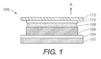
- FIG. 1is a simplified cross-sectional depiction of an electroluminescent component as can be included in analytical test strips according to embodiments of the present invention
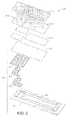
- FIG. 2is a perspective exploded view of an analytical test strip including an electroluminescent module according to an exemplary embodiment of the present invention
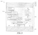
- FIG. 3is a simplified schematic diagram of a portion of an analytical test strip according to another embodiment of the present invention that includes a simplified depiction of a fluorescent chemical reaction sequence occurring within a sample chamber of the analytical test strip;
- FIG. 4is a simplified schematic diagram of a portion of an analytical test strip according to yet another exemplary embodiment of the present invention that includes a simplified depiction of a fluorescent chemical reaction sequence occurring within a sample chamber of the analytical test strip;
- FIG. 5is a simplified schematic depiction of a system for the determination of an analyte in a bodily fluid sample according to an exemplary embodiment of the present invention
- FIG. 6is a flow diagram depicting stages in a process for determining an analyte in a bodily fluid sample according to an exemplary embodiment of the present invention
- FIG. 7is a simplified top view of an analytical test strip with an electroluminescent lamp according to an exemplary embodiment of the present invention.
- FIG. 8is a simplified top view of an analytical test strip with an electroluminescent lamp according to another exemplary embodiment of the present invention.
- FIG. 9is a simplified top view of an analytical test strip with an electroluminescent lamp according to yet another exemplary embodiment of the present invention.
- FIG. 10is a flow diagram depicting stages in a process for manufacturing an analytical test strip for determination of an analyte in a bodily fluid sample according to an exemplary embodiment of the present invention.
- FIG. 11is a simplified depiction of a continuous web printing apparatus as can be employed in embodiments of the present invention.
- An analytical test strip for the determination of an analyte (such as glucose) in a bodily fluid sampleincludes a substrate layer, an electroluminescent module disposed on the substrate layer, a sample chamber (such as a capillary sample chamber) configured for receiving the bodily fluid sample disposed above the substrate layer and a fluorophore-containing photometric enzymatic reagent disposed within the sample chamber.
- the electroluminescent moduleis in optical communication with the sample chamber and is configured to emit light that facilitates a fluorescent chemical reaction sequence between the fluorophore-containing photometric enzymatic reagent and the analyte. Further details of such analytical test strips are described below and, in particular, with respect to FIGS. 1 , 2 , 3 and 4 .
- An analytical test strip for the determination of an analyte (such as glucose) in a bodily fluid samplefor example, a whole blood sample
- a bodily fluid samplefor example, a whole blood sample
- an analytesuch as glucose
- a bodily fluid samplefor example, a whole blood sample
- an electroluminescent lampdisposed on the substrate layer
- a sample chamberconfigured for receiving the bodily fluid sample disposed above the substrate layer
- an enzymatic reagentdisposed within the sample chamber.
- the electroluminescent lampis configured to emit light, the light being visible to a user of the analytical test strip and providing the user with spatial awareness of the analytical test strip. Further details of such analytical test strips are described below and, in particular, with respect to FIGS. 1 , 7 , 8 and 9 .
- FIG. 1is a simplified cross-sectional depiction of an electroluminescent component 100 as can be included in analytical test strips according to embodiments of the present invention.
- Electroluminescent component 100can serve as either an electroluminescent module (as described with respect to, for example, FIGS. 2 , 3 and 4 ) or as an electroluminescent lamp (as described with respect to, for example, FIGS. 7 , 8 and 9 ). However, for the sake of simplicity, electroluminescent component 100 will be referred to as an electroluminescent module hereafter.
- Electroluminescent module 100includes a substrate layer 102 , a rear electrode layer 104 , an electrically-insulating layer 106 disposed over the rear electrode layer, a phosphor layer 108 disposed over electrically-insulating layer 106 , and a front electrode layer 110 , at least a portion of which is translucent to light emitted by phosphor layer 108 , disposed over phosphor layer 108 .
- Electroluminescent module 100also includes an encapsulant layer 112 disposed over front electrode layer 110 .
- Substrate layer 102can be formed of any suitable substrate layer material including, for example, a polyester substrate layer material or a commercially available Melinex® ST328 (manufactured by DuPont Teijin Films) substrate layer material.
- Rear electrode layer 104can be formed of any suitable electrically conductive material including, for example, indium tin oxide (ITO) that has been sputtered onto substrate layer 102 or gold.
- Rear electrode layer 104can also be formed of carbon ink, silver paste or an electrically conductive polymer.
- rear electrode layer 104can be, if desired, of any suitable pattern and can also be, for example, formed using conventional techniques such as screen-printing, laser ablation and photolithography.
- Electrically insulating layer 106can be formed, for example, of polyester, acrylic, or epoxy-based ink materials. Electrically insulating layer 106 serves to prevent undesirable short circuits when an AC current is applied across electroluminescent module 100 to induce the emission of light from phosphor layer 108 and, subsequently, from electroluminescent module 100 .
- the AC currentcan be applied, for example, when analytical test strips according to embodiments of the present invention are inserted into an associated analytical meter.
- Phosphor layer 108can be formed of any suitable phosphor material known to one skilled in the art as suitable for use in an electroluminescent module or electroluminescent lamp. Examples of such phosphor materials are described in U.S. Pat. No. 5,675,217, which is hereby incorporated in full by reference. Moreover, the phosphor can, for example, include zinc chloride micro-crystals.
- Front electrode layer 110can be formed, for example, of translucent Indium Tin Oxide (ITO) or translucent gold for example. Light emitted from electroluminescent module 100 will pass through the translucent portion of front electrode layer 110 in, for example, the direction of arrow A in FIG. 1 .
- ITOIndium Tin Oxide
- Encapsulant layer 112is configured to provide a moisture barrier and, thus, protect phosphor layer 108 from moisture-induced degradation while still providing for light to be emitted from electroluminescent module 100 . Therefore, encapsulant layer 112 can be formed, for example, of any suitably transparent and moisture impermeable material. Suitable materials include epoxy resins, silicones and polyurethanes. Moreover, as described in more detail below, a wavelength modulator can be embedded or dispersed within encapsulate layer 112 .
- FIG. 2is a simplified perspective and exploded view of an analytical test strip 200 according to an embodiment of the present invention.
- Analytical test strip 200includes a substrate layer 202 (depicted by dashed lines), an electroluminescent module 204 (including substrate layer 202 as well as a rear electrode layer 206 , an electrically-insulating layer 208 , a phosphor layer 210 , a front electrode layer 212 and an encapsulant layer 214 ), and a sample chamber 216 (defined by adhesive layer 218 , anti-fog layer 220 , and top layer 222 ).
- sample chamber 216is a capillary sample chamber.
- a fluorophore-containing photometric enzymatic reagent(not shown in FIG. 2 ) disposed within sample chamber 216 .
- a fluorophore-containing photometric enzymatic reagentcould be, for example, disposed as a layer between encapsulant layer 214 and adhesive layer 218 .
- fluorophore-containing photometric enzymatic reagents employed in embodiments of the present inventioninclude (i) enzymes specific to a predetermined analyte and fluorescent chemical reaction sequence of interest, such as glucose oxidase and horseradish peroxidase (HRP) respectively and (ii) a fluorophore, such as, for example, Amplex Red reagent (i.e., 10-acetyl-3,7-duhydroxypehnoxazinne reagent), the proprietary and commercially available fluorophore DuoLux, coumarin, fluorescene isothio cynate (FITC), fluorescamine, and cascade blue.
- Amplex Red reagenti.e., 10-acetyl-3,7-duhydroxypehnoxazinne reagent
- FITCfluorescamine
- fluorophoreincludes, but is not limited to, reagents such as Amplex Red reagent that are themselves non-fluorescent but that serve as fluorogenic probes by producing, for example, a fluorescent dye during a fluorescent chemical reaction sequence involving the fluorophore-containing photometric reagent, the analyte and light emitted from the electroluminescent module.
- fluorescent chemical reaction sequencesare described further below with respect to FIGS. 3 and 4 .
- the fluorophore-containing photometric enzymatic reagentscan also contain, for example, a suitable buffer (such as a citrate buffer, a phosphate buffer, or a citraconate buffer) and a binder (e.g., HEC (hydroxyethly cellulose), PVA (polyvinyl alcohol), polyaniline, or CMC (carboxymethylcellulose)).
- a suitable buffersuch as a citrate buffer, a phosphate buffer, or a citraconate buffer
- a bindere.g., HEC (hydroxyethly cellulose), PVA (polyvinyl alcohol), polyaniline, or CMC (carboxymethylcellulose)
- the enzyme included in the fluorophore-containing photometric enzymatic reagentis predetermined based on the analyte of interest. Therefore, other suitable enzymes include, but are nor limited to, cholesterol oxidase (for the analyte cholesterol) and amino-acid oxidase (for various amino acid analytes).
- fluorescent light emitted from phosphor layer 210 of electroluminescent module 204propagates through front electrode layer 212 and encapsulant layer 214 to reach sample chamber 216 . The fluorescent light then facilitates a fluorescent chemical reaction sequence involving the fluorophore-containing photometric enzymatic reagent and the analyte within sample chamber 216 .
- FIG. 3is a simplified schematic diagram of a portion of an analytical test strip 300 according to another embodiment of the present invention that includes a simplified depiction of a fluorescent chemical reaction sequence occurring within a sample chamber of the analytical test strip.
- Portion 300includes an electroluminescent module 302 , a sample chamber 304 , a photodetector 306 , an adhesive layer 308 , an anti-fog layer 310 and a top layer 312 .
- sample chamber 304has a sample inlet 314 whereby a bodily fluid sample (e.g., a whole blood sample) is introduced into sample chamber 304 .
- a bodily fluid samplee.g., a whole blood sample
- a fluorescent chemical reaction sequenceoccurs within sample chamber 304 .
- the fluorescent chemical reaction sequenceincludes the following reactions involving the bodily fluid sample (and analyte therein), the fluorophore-containing photometric enzymatic reagent and light from electroluminescent module 302 (depicted by the arrows labeled A in FIG. 3 ):
- an analytee.g., glucose
- enzymee.g., glucose oxidase
- H 2 O 2reacts with a fluorophore (e.g., Amplex Red reagent) and horseradish peroxidase (HRP), under the influence of light from electroluminescent module 302 , to produce a fluorescent molecule (e.g., resorufin); and
- a fluorophoree.g., Amplex Red reagent
- HRPhorseradish peroxidase
- the fluorescence of the fluorescent moleculeresults in the emission emits photons proportional to the concentration of analyte in the bodily fluid sample.
- These photonsare then detected by photodetector 306 , that is disposed in a co-facial arrangement with respect to electroluminescent module 302 .
- Photodetector 306can be formed, for example, from cadmium sulphide and cadmium selenide in the form of a resistive electrode.
- FIG. 4is a simplified schematic diagram of a portion of an analytical test strip 400 according to yet another exemplary embodiment of the present invention that includes a simplified depiction of a fluorescent chemical reaction sequence occurring within a sample chamber of the analytical test strip.
- Portion 400includes an electroluminescent module 402 , a sample chamber 404 , a photodetector 406 , an adhesive layer 408 , an anti-fog layer 410 and a top layer 412 .
- sample chamber 404has a sample inlet 414 whereby a bodily fluid sample (e.g., a whole blood sample) is introduced into sample chamber 404 .
- a bodily fluid samplee.g., a whole blood sample
- a fluorescent chemical reaction sequenceoccurs within sample chamber 404 .
- the fluorescent chemical reaction sequenceincludes the following general reactions involving the bodily fluid sample (and analyte therein), the fluorophore-containing photometric enzymatic reagent and light from electroluminescent module 402 (depicted by the arrows labeled A in FIG. 4 ):
- an analyte+an analyte-specific enzymereact to produce a product+H 2 O 2 ;
- H 2 O 2reacts with a fluorophore and HRP, under the influence of light from electroluminescent module 402 , to produce a fluorescent molecule (not shown in FIG. 4 );
- the fluorescence of the fluorescent moleculeresults in the emission of photons proportional to the concentration of analyte in the bodily fluid sample.
- photodetector 406which is disposed in a co-planar arrangement with respect to electroluminescent module 402 .
- Such a co-planar arrangementcan be beneficial in reducing interference with photodetector 406 by light from electroluminescent module 402 .
- the photons reaching photodetector 406are converted into a current. The current is translated into an analyte concentration by software within an associated analytical meter.
- light from electroluminescent modules in embodiments of the present inventionserves to drive photochemistry of the fluorescent chemical reaction sequence.
- Such photochemically-driven fluorescent chemical reactions sequencesare expected to provide highly precise and accurate analyte determinations via photon amplification (multiplication) behavior.
- the absorbance maximum of Amplex Red reagentis at approximately 560 nm and its emission maximum is at approximately 590 nm.
- a fluorescent product of Amplex Red reagentis resorufin, which has absorption and emission maxima that are sufficiently distinct from those of Amplex Red reagent such that there is expected to be little interference from auto-fluorescence for a majority of bodily fluid samples.
- Electroluminescent modules and lamps employed in embodiments of the present inventionwould typically emit light in the blue-green wavelength region of the visible spectrum, at approximately 490 nm. However, for purposes of driving a fluorescent chemical reaction sequence, it can be advantageous to use excitation light in the orange-red wavelength region that is obtained by wavelength modulation of light emitted by a phosphor layer of an electroluminescent module. Such wavelength modulation is known, in general, as a Stoke's shift.
- wavelength modulationcan be used to provide light of an appropriate wavelength and intensity for use with fluorophore-containing photometric enzymatic reagents that include Amplex Red reagent.
- wavelength modulationcan be achieved using, for example, fluorescein (with an absorption peak around 490 nm, and an emission spectrum with a maximum around 520 nm) or rhodamine with a maximum absorption around 530 nm, and a broad emission spectrum up to approximately 700 nm.
- Wavelength modulatorssuch as fluorescein and rhodamine
- electroluminescent modulesand electroluminescent lamps
- Wavelength modulatorscan be incorporated into electroluminescent modules (and electroluminescent lamps) by, for example, dispersing or embedding the wavelength modulator into an encapsulant layer or by formation as an independent layer above or below an encapsulant layer.
- FIG. 5is a simplified schematic depiction of a system 500 for the determination of an analyte in a bodily fluid sample according to an exemplary embodiment of the present invention.
- System 500includes an analytical test strip 502 and an analytical meter 504 .
- Analytical test strip 502can be any suitable analytical test strip according to embodiments of the present invention. Therefore, analytical test strip 502 has a substrate layer, an electroluminescent component (either an electroluminescent module and/or an electroluminescent lamp) disposed on the substrate layer, and a sample chamber configured for receiving a bodily fluid sample disposed above the substrate layer. Analytical meter 504 is configured for insertion of the analytical test strip therein and subsequent determination of the analyte as described elsewhere herein.
- electroluminescent componenteither an electroluminescent module and/or an electroluminescent lamp
- FIG. 6is a flow diagram depicting stages in a method 600 for determining an analyte (such as glucose) in a bodily fluid sample (for example a whole blood sample) according to an exemplary embodiment of the present invention.
- Method 600includes transferring a bodily fluid sample to a sample chamber of an analytical test strip, as set forth in step 610 .
- the analytical test strip to which the bodily fluid sample is transferredincludes a substrate layer, an electroluminescent module disposed on the substrate layer and in optical communication with the sample chamber, a fluorophore-containing photometric enzymatic reagent disposed within the sample chamber.
- the electroluminescent module of the analytical test stripis configured to emit light that facilitates a fluorescent chemical reaction sequence involving the fluorophore-containing photometric enzymatic reagent and the analyte.
- Method 600also includes, at step 620 , exposing the fluorophore-containing photometric enzymatic reagent to the bodily fluid sample and to light emitted from the electroluminescent module such that photons are emitted from the fluorophore-containing photometric enzymatic reagent via a fluorescent chemical reaction sequence. The photons are then detected with a photodetector, as set forth in step 630 .
- FIG. 7is a simplified top view of an analytical test strip 700 with an electroluminescent lamp according to an exemplary embodiment of the present invention.
- Analytical test strip 700includes a substrate layer (not shown), an electroluminescent lamp 702 disposed on the substrate layer, a sample chamber 704 configured for receiving the bodily fluid sample disposed above the substrate layer and an enzymatic reagent (not depicted) disposed within the sample chamber.
- Analytical test strip 700also includes electrical contacts 706 for conducting power and signals to and from various components of the analytical test strip.
- Electroluminescent lamp 702is configured to emit light, the light being visible to a user of the analytical test strip and providing the user with spatial awareness of the analytical test strip.
- electroluminescent lamp 702is configured to emit light that appears as two directional arrows to a user, with the directional arrows indicating a bodily fluid sample application area of the analytical test strip.
- FIG. 8is a simplified top view of an analytical test strip 800 with an electroluminescent lamp according to another exemplary embodiment of the present invention.
- Analytical test strip 800includes a substrate layer (not shown), an electroluminescent lamp 802 disposed on the substrate layer, a sample chamber 804 configured for receiving the bodily fluid sample disposed above the substrate layer and an enzymatic reagent (not depicted) disposed within the sample chamber.
- Analytical test strip 800also includes electrical contacts 806 for conducting power and signals to and from various components of the analytical test strip.
- Electroluminescent lamp 802is configured to emit light, the light being visible to a user of the analytical test strip and providing the user with spatial awareness of the analytical test strip.
- electroluminescent lamp 802is configured to emit light in a continuous band along a distal end 808 of the analytical test strip where the bodily fluid sample is to be applied.
- FIG. 9is a simplified top view of an analytical test strip 900 with an electroluminescent lamp according to yet another exemplary embodiment of the present invention.
- Analytical test strip 900includes a substrate layer (not shown), an electroluminescent lamp 902 disposed on the substrate layer, a sample chamber 904 configured for receiving the bodily fluid sample disposed above the substrate layer and an enzymatic reagent (not depicted) disposed within the sample chamber.
- Analytical test strip 900also includes electrical contacts 906 for conducting power and signals to and from various components of the analytical test strip.
- Electroluminescent lamp 902is configured to emit light, the light being visible to a user of the analytical test strip and providing the user with spatial awareness of the analytical test strip.
- electroluminescent lamp 902is configured to emit light along a periphery of the sample chamber (for example, a capillary sample chamber) to facilitate visual determination of complete capillary sample fill by a bodily fluid sample.
- analytical test strips with electroluminescent lamps according to embodiments of the present inventioncan employ and suitable features and characteristics of analytical test strips with electroluminescent modules and systems according to embodiments of the present invention.
- analytical test strips with electroluminescent lamps according to embodiments of the present inventioncan be electrochemical-based analytical test strips or photochemical-based analytical test strips.
- FIG. 10is a flow diagram depicting stages in a method 1000 for manufacturing an analytical test strip for determination of an analyte (such as glucose) in a bodily fluid sample (for example a whole blood sample) according to an exemplary embodiment of the present invention.
- FIG. 11is a simplified depiction of a continuous web printing apparatus 1100 as can be employed in method 1000 and other method embodiments of the present invention.
- method 1000includes at step 1010 , sequentially applying to a substrate layer, a:
- a front electrode layerat least a portion of which is translucent, disposed over the phosphor layer.
- the sequential applicationis accomplished such that it forms an electroluminescent component (either an electroluminescent lamp or an electroluminescent module as described herein with respect to various embodiments of the present invention) of the analytical test strip.
- any of the sequential applicationscan be followed by a drying step prior to the next sequential application (i.e., an intermittent drying step).
- an encapsulant layercan also be sequentially applied.
- Method 1000can be accomplished using screen-printing technology, flat-bed printing, continuous web-based printing technology or any combination thereof.
- continuous web-based printing technologycan be especially beneficial in terms of printing yield and alignment.
- continuous web printing apparatus 1100can be employed with a substrate 1104 to conduct method 1000 .
- an optional preconditioning station 1106 , a rear electrode layer print station 1108 , a first dryer 1110 , an electrically-insulating layer print station 1112 , a second dryer 1114 , a phosphor layer print station 1116 , a third dryer 1118 , a translucent front electrode layer print station 1120 , a fourth dryer 1122 and an encapsulant layer print station 1124can be employed to manufacture analytical tests strips.
- analytical test strips according to the present inventioncan be used to manufacture analytical test strips according to the present invention including, but not limited to, analytical test strips as depicted in FIGS. 2 , 3 , 4 , 7 , 8 and 9 .
Landscapes
- Chemical & Material Sciences (AREA)
- Health & Medical Sciences (AREA)
- Physics & Mathematics (AREA)
- General Physics & Mathematics (AREA)
- Life Sciences & Earth Sciences (AREA)
- Analytical Chemistry (AREA)
- Biochemistry (AREA)
- General Health & Medical Sciences (AREA)
- Immunology (AREA)
- Pathology (AREA)
- Nuclear Medicine, Radiotherapy & Molecular Imaging (AREA)
- Engineering & Computer Science (AREA)
- Chemical Kinetics & Catalysis (AREA)
- Plasma & Fusion (AREA)
- Investigating Or Analysing Materials By The Use Of Chemical Reactions (AREA)
- Investigating, Analyzing Materials By Fluorescence Or Luminescence (AREA)
Abstract
Description
Claims (11)
Priority Applications (9)
| Application Number | Priority Date | Filing Date | Title |
|---|---|---|---|
| US11/591,138US7740801B2 (en) | 2006-10-31 | 2006-10-31 | System for determination of an analyte in a bodily fluid sample that includes an electroluminescent component |
| JP2007281115AJP2008116453A (en) | 2006-10-31 | 2007-10-30 | Analytical test strip with electroluminescent lamp |
| CA 2608924CA2608924A1 (en) | 2006-10-31 | 2007-10-30 | Analytical test strip with electroluminescent module |
| JP2007281113AJP2008116452A (en) | 2006-10-31 | 2007-10-30 | Analytical specimen having an electroluminescent module |
| CA 2608609CA2608609A1 (en) | 2006-10-31 | 2007-10-30 | Analytical test strip with electroluminescent lamp |
| EP07254291AEP1918708A3 (en) | 2006-10-31 | 2007-10-30 | Analytical test strip with electroluminescent lamp |
| EP07254286AEP1918707A3 (en) | 2006-10-31 | 2007-10-30 | Analytical test strip with electroluminescent module |
| CN200710159616.3ACN101261269A (en) | 2006-10-31 | 2007-10-31 | Analytical test strips with electroluminescent lamps |
| CN200710159641.1ACN101187662A (en) | 2006-10-31 | 2007-10-31 | Analytical test strips with electroluminescence module |
Applications Claiming Priority (1)
| Application Number | Priority Date | Filing Date | Title |
|---|---|---|---|
| US11/591,138US7740801B2 (en) | 2006-10-31 | 2006-10-31 | System for determination of an analyte in a bodily fluid sample that includes an electroluminescent component |
Publications (2)
| Publication Number | Publication Date |
|---|---|
| US20080101985A1 US20080101985A1 (en) | 2008-05-01 |
| US7740801B2true US7740801B2 (en) | 2010-06-22 |
Family
ID=39330401
Family Applications (1)
| Application Number | Title | Priority Date | Filing Date |
|---|---|---|---|
| US11/591,138Expired - Fee RelatedUS7740801B2 (en) | 2006-10-31 | 2006-10-31 | System for determination of an analyte in a bodily fluid sample that includes an electroluminescent component |
Country Status (2)
| Country | Link |
|---|---|
| US (1) | US7740801B2 (en) |
| CN (2) | CN101261269A (en) |
Cited By (6)
| Publication number | Priority date | Publication date | Assignee | Title |
|---|---|---|---|---|
| US8858884B2 (en) | 2013-03-15 | 2014-10-14 | American Sterilizer Company | Coupled enzyme-based method for electronic monitoring of biological indicator |
| US9121050B2 (en) | 2013-03-15 | 2015-09-01 | American Sterilizer Company | Non-enzyme based detection method for electronic monitoring of biological indicator |
| US9877672B2 (en) | 2010-01-28 | 2018-01-30 | Ellume Pty Ltd | Sampling and testing device for the human or animal body |
| US10571402B2 (en)* | 2015-04-10 | 2020-02-25 | Nokia Technologies Oy | Apparatus and method for sensing |
| US10786229B2 (en) | 2015-01-22 | 2020-09-29 | Ellume Limited | Diagnostic devices and methods for mitigating hook effect and use thereof |
| US10890590B2 (en) | 2012-09-27 | 2021-01-12 | Ellume Limited | Diagnostic devices and methods |
Families Citing this family (2)
| Publication number | Priority date | Publication date | Assignee | Title |
|---|---|---|---|---|
| EP2408931A2 (en)* | 2009-03-20 | 2012-01-25 | Roche Diagnostics GmbH | Test element for determining a body fluid and measurement method |
| GB2523135A (en)* | 2014-02-13 | 2015-08-19 | Molecular Vision Ltd | Assay device |
Citations (23)
| Publication number | Priority date | Publication date | Assignee | Title |
|---|---|---|---|---|
| US3052810A (en) | 1957-02-18 | 1962-09-04 | Thorn Electrical Ind Ltd | Electro-luminescent lamps |
| USH44H (en)* | 1983-05-11 | 1986-04-01 | The United States Of America As Represented By The Secretary Of The Navy | Electronic phase shifter having a constant magnitude output |
| US4935346A (en)* | 1986-08-13 | 1990-06-19 | Lifescan, Inc. | Minimum procedure system for the determination of analytes |
| WO1994017556A1 (en)* | 1993-01-26 | 1994-08-04 | Fci-Fiberchem, Inc. | Optical sensor with electroluminescent light source and polymer light detector |
| US5453360A (en) | 1992-02-03 | 1995-09-26 | Lifescan, Inc. | Oxidative coupling dye for spectrophotometric quantitive analysis of analytes |
| US5453359A (en)* | 1988-06-13 | 1995-09-26 | American Biogenetic Sciences, Inc. | Immunoassay and kit for in vitro detection of soluble DesAABB fibrin polymers |
| US5675217A (en) | 1994-12-08 | 1997-10-07 | Lg Semicon Co., Ltd. | Color electroluminescent device and method of manufacturing the same |
| US5753452A (en) | 1996-04-04 | 1998-05-19 | Lifescan, Inc. | Reagent test strip for blood glucose determination |
| US6168957B1 (en) | 1997-06-25 | 2001-01-02 | Lifescan, Inc. | Diagnostic test strip having on-strip calibration |
| WO2001038857A1 (en) | 1999-11-24 | 2001-05-31 | Iowa State University Research Foundation, Inc. | Optical sensors and arrays containing thin film electroluminescent devices |
| US6514460B1 (en) | 1999-07-28 | 2003-02-04 | Abbott Laboratories | Luminous glucose monitoring device |
| EP1288653A1 (en)* | 2001-08-29 | 2003-03-05 | Roche Diagnostics GmbH | Biosensor with a bar code |
| US6555061B1 (en)* | 2000-10-05 | 2003-04-29 | Lifescan, Inc. | Multi-layer reagent test strip |
| US20030218420A1 (en) | 2002-05-21 | 2003-11-27 | Zovko Charles I. | EL lamp with light scattering particles in cascading layer |
| US6743164B2 (en)* | 1999-06-02 | 2004-06-01 | Music Of The Plants, Llp | Electronic device to detect and generate music from biological microvariations in a living organism |
| US6800722B2 (en) | 2001-05-23 | 2004-10-05 | Sri International | Electroluminescent polymers and use thereof in light-emitting devices |
| US6821482B1 (en) | 1995-04-28 | 2004-11-23 | Commonwealth Scientific And Industrial Research Organisation | Triggered active packaging material |
| US20050023972A1 (en) | 2003-07-29 | 2005-02-03 | Lewandowski Mark A. | Method for printing electroluminescent lamps |
| US20050023137A1 (en) | 2003-06-20 | 2005-02-03 | Bhullar Raghbir S. | Biosensor with multiple electrical functionalities |
| WO2005078438A2 (en) | 2004-02-13 | 2005-08-25 | Arctic Diagnostics Oy | Use of two-photon excited fluorescence in assays of clinical chemistry analytes |
| WO2005103652A1 (en) | 2004-04-21 | 2005-11-03 | Ausbiochip Pty Ltd | Optoelectronic biochip |
| EP1672356A1 (en) | 2004-12-17 | 2006-06-21 | Agilent Technologies, Inc. | Sensor having integrated light detector and/or light source |
| GB2431231A (en) | 2005-10-07 | 2007-04-18 | Michael O'reilly | Screen printable optical spectrophotometer for diagnostic applications |
Family Cites Families (2)
| Publication number | Priority date | Publication date | Assignee | Title |
|---|---|---|---|---|
| JP3628194B2 (en)* | 1998-12-24 | 2005-03-09 | 株式会社デンソー | Method for forming primary spool of ignition coil |
| US20030023972A1 (en)* | 2001-07-26 | 2003-01-30 | Koninklijke Philips Electronics N.V. | Method for charging advertisers based on adaptive commercial switching between TV channels |
- 2006
- 2006-10-31USUS11/591,138patent/US7740801B2/ennot_activeExpired - Fee Related
- 2007
- 2007-10-31CNCN200710159616.3Apatent/CN101261269A/enactivePending
- 2007-10-31CNCN200710159641.1Apatent/CN101187662A/enactivePending
Patent Citations (24)
| Publication number | Priority date | Publication date | Assignee | Title |
|---|---|---|---|---|
| US3052810A (en) | 1957-02-18 | 1962-09-04 | Thorn Electrical Ind Ltd | Electro-luminescent lamps |
| USH44H (en)* | 1983-05-11 | 1986-04-01 | The United States Of America As Represented By The Secretary Of The Navy | Electronic phase shifter having a constant magnitude output |
| US5426032A (en) | 1986-08-13 | 1995-06-20 | Lifescan, Inc. | No-wipe whole blood glucose test strip |
| US4935346A (en)* | 1986-08-13 | 1990-06-19 | Lifescan, Inc. | Minimum procedure system for the determination of analytes |
| US5453359A (en)* | 1988-06-13 | 1995-09-26 | American Biogenetic Sciences, Inc. | Immunoassay and kit for in vitro detection of soluble DesAABB fibrin polymers |
| US5453360A (en) | 1992-02-03 | 1995-09-26 | Lifescan, Inc. | Oxidative coupling dye for spectrophotometric quantitive analysis of analytes |
| WO1994017556A1 (en)* | 1993-01-26 | 1994-08-04 | Fci-Fiberchem, Inc. | Optical sensor with electroluminescent light source and polymer light detector |
| US5675217A (en) | 1994-12-08 | 1997-10-07 | Lg Semicon Co., Ltd. | Color electroluminescent device and method of manufacturing the same |
| US6821482B1 (en) | 1995-04-28 | 2004-11-23 | Commonwealth Scientific And Industrial Research Organisation | Triggered active packaging material |
| US5753452A (en) | 1996-04-04 | 1998-05-19 | Lifescan, Inc. | Reagent test strip for blood glucose determination |
| US6168957B1 (en) | 1997-06-25 | 2001-01-02 | Lifescan, Inc. | Diagnostic test strip having on-strip calibration |
| US6743164B2 (en)* | 1999-06-02 | 2004-06-01 | Music Of The Plants, Llp | Electronic device to detect and generate music from biological microvariations in a living organism |
| US6514460B1 (en) | 1999-07-28 | 2003-02-04 | Abbott Laboratories | Luminous glucose monitoring device |
| WO2001038857A1 (en) | 1999-11-24 | 2001-05-31 | Iowa State University Research Foundation, Inc. | Optical sensors and arrays containing thin film electroluminescent devices |
| US6555061B1 (en)* | 2000-10-05 | 2003-04-29 | Lifescan, Inc. | Multi-layer reagent test strip |
| US6800722B2 (en) | 2001-05-23 | 2004-10-05 | Sri International | Electroluminescent polymers and use thereof in light-emitting devices |
| EP1288653A1 (en)* | 2001-08-29 | 2003-03-05 | Roche Diagnostics GmbH | Biosensor with a bar code |
| US20030218420A1 (en) | 2002-05-21 | 2003-11-27 | Zovko Charles I. | EL lamp with light scattering particles in cascading layer |
| US20050023137A1 (en) | 2003-06-20 | 2005-02-03 | Bhullar Raghbir S. | Biosensor with multiple electrical functionalities |
| US20050023972A1 (en) | 2003-07-29 | 2005-02-03 | Lewandowski Mark A. | Method for printing electroluminescent lamps |
| WO2005078438A2 (en) | 2004-02-13 | 2005-08-25 | Arctic Diagnostics Oy | Use of two-photon excited fluorescence in assays of clinical chemistry analytes |
| WO2005103652A1 (en) | 2004-04-21 | 2005-11-03 | Ausbiochip Pty Ltd | Optoelectronic biochip |
| EP1672356A1 (en) | 2004-12-17 | 2006-06-21 | Agilent Technologies, Inc. | Sensor having integrated light detector and/or light source |
| GB2431231A (en) | 2005-10-07 | 2007-04-18 | Michael O'reilly | Screen printable optical spectrophotometer for diagnostic applications |
Non-Patent Citations (3)
| Title |
|---|
| Mao, H.; Yang, T.; Cremer, P.S. "Design and Characterization of Immobilized Enzymes in Microfluidic Systems" Analytical Chemistry, 2002, 74 (2), pp. 379-385.* |
| Savvate'Ev, V., et al., "Integrated Organic Light-Emitting Device/Fluorescence-Based Chemical Sensors", Applied Physics Letters, vol. 81, No. 24, Dec. 9, 2002, pp. 4652-4654. |
| Zhou, Mingjie, et al., "A Stable Nonfluorescent Derivative of Resorufin for the Fluorometric Determination of Trace Hydrogen Peroxide: Applications in Detecting the Activity of Phagocyte NADPH Oxidase and Other Oxidases", Analytical Biochemistry, vol. 253, No. 2, Nov. 15, 1997, pp. 162-168. |
Cited By (6)
| Publication number | Priority date | Publication date | Assignee | Title |
|---|---|---|---|---|
| US9877672B2 (en) | 2010-01-28 | 2018-01-30 | Ellume Pty Ltd | Sampling and testing device for the human or animal body |
| US10890590B2 (en) | 2012-09-27 | 2021-01-12 | Ellume Limited | Diagnostic devices and methods |
| US8858884B2 (en) | 2013-03-15 | 2014-10-14 | American Sterilizer Company | Coupled enzyme-based method for electronic monitoring of biological indicator |
| US9121050B2 (en) | 2013-03-15 | 2015-09-01 | American Sterilizer Company | Non-enzyme based detection method for electronic monitoring of biological indicator |
| US10786229B2 (en) | 2015-01-22 | 2020-09-29 | Ellume Limited | Diagnostic devices and methods for mitigating hook effect and use thereof |
| US10571402B2 (en)* | 2015-04-10 | 2020-02-25 | Nokia Technologies Oy | Apparatus and method for sensing |
Also Published As
| Publication number | Publication date |
|---|---|
| CN101187662A (en) | 2008-05-28 |
| CN101261269A (en) | 2008-09-10 |
| US20080101985A1 (en) | 2008-05-01 |
Similar Documents
| Publication | Publication Date | Title |
|---|---|---|
| US7740801B2 (en) | System for determination of an analyte in a bodily fluid sample that includes an electroluminescent component | |
| US20080101986A1 (en) | Analytical test strip with electroluminescent module | |
| D'Orazio | Biosensors in clinical chemistry | |
| Zhu et al. | A paper electrode integrated lateral flow immunosensor for quantitative analysis of oxidative stress induced DNA damage | |
| US7476827B1 (en) | Method of making a biosensor | |
| Liu et al. | A novel paperfluidic closed bipolar electrode-electrochemiluminescence sensing platform: Potential for multiplex detection at crossing-channel closed bipolar electrodes | |
| EP1918707A2 (en) | Analytical test strip with electroluminescent module | |
| EP1918708A2 (en) | Analytical test strip with electroluminescent lamp | |
| US20050176133A1 (en) | Measuring instrument for biosensor and measuring method using same | |
| JP4991882B2 (en) | Electrochemical biosensor measurement system | |
| US20050023137A1 (en) | Biosensor with multiple electrical functionalities | |
| JPWO2005075979A1 (en) | Biosensor, biosensor measuring apparatus, and measuring method | |
| Fiaccabrino et al. | On-chip generation and detection of electrochemiluminescence | |
| CN101641592A (en) | Electrochemical biosensor measuring system | |
| CN102132150A (en) | Biosensor measuring device and method thereof | |
| US20110094882A1 (en) | Test meter for use with a dual chamber, multi-analyte test strip with opposing electrodes | |
| EP1830177A1 (en) | Integrated test element | |
| CN102520173B (en) | Fluorescence immunochromatographic assay and kit for quantitative detection of creatine kinase isoenzyme (CK-MB) | |
| US20080101987A1 (en) | Analytical test strip with electroluminescent lamp | |
| CN111024786A (en) | A method for establishing a closed bipolar electrochemiluminescence detection platform based on quantum dots and its application | |
| US20080101984A1 (en) | Method for determining an analyte in a bodily fluid sample | |
| US20080100689A1 (en) | Method for manufacturing an analytical test strip with an electroluminescent component | |
| EP3635381A1 (en) | Metabolite detection apparatus and corresponding detection method | |
| HK1117230A (en) | Analytical test strip with electroluminescent module | |
| HK1116542A (en) | Analytical test strip with electroluminescent lamp |
Legal Events
| Date | Code | Title | Description |
|---|---|---|---|
| AS | Assignment | Owner name:LIFESCAN SCOTLAND LIMITED, UNITED KINGDOM Free format text:ASSIGNMENT OF ASSIGNORS INTEREST;ASSIGNORS:SAINI, SELWAYAN;CARDOSI, MARCO FABIO;MILLS, LEANNE;AND OTHERS;REEL/FRAME:018749/0561 Effective date:20061201 Owner name:LIFESCAN SCOTLAND LIMITED,UNITED KINGDOM Free format text:ASSIGNMENT OF ASSIGNORS INTEREST;ASSIGNORS:SAINI, SELWAYAN;CARDOSI, MARCO FABIO;MILLS, LEANNE;AND OTHERS;REEL/FRAME:018749/0561 Effective date:20061201 | |
| STCF | Information on status: patent grant | Free format text:PATENTED CASE | |
| FPAY | Fee payment | Year of fee payment:4 | |
| MAFP | Maintenance fee payment | Free format text:PAYMENT OF MAINTENANCE FEE, 8TH YEAR, LARGE ENTITY (ORIGINAL EVENT CODE: M1552) Year of fee payment:8 | |
| AS | Assignment | Owner name:BANK OF AMERICA, N.A., AS COLLATERAL AGENT, NORTH CAROLINA Free format text:SECURITY AGREEMENT;ASSIGNOR:LIFESCAN IP HOLDINGS, LLC;REEL/FRAME:047179/0150 Effective date:20181001 Owner name:BANK OF AMERICA, N.A., AS COLLATERAL AGENT, NORTH Free format text:SECURITY AGREEMENT;ASSIGNOR:LIFESCAN IP HOLDINGS, LLC;REEL/FRAME:047179/0150 Effective date:20181001 | |
| AS | Assignment | Owner name:BANK OF AMERICA, N.A., AS COLLATERAL AGENT, NORTH CAROLINA Free format text:SECURITY AGREEMENT;ASSIGNOR:LIFESCAN IP HOLDINGS, LLC;REEL/FRAME:047186/0836 Effective date:20181001 Owner name:BANK OF AMERICA, N.A., AS COLLATERAL AGENT, NORTH Free format text:SECURITY AGREEMENT;ASSIGNOR:LIFESCAN IP HOLDINGS, LLC;REEL/FRAME:047186/0836 Effective date:20181001 | |
| AS | Assignment | Owner name:LIFESCAN IP HOLDINGS, LLC, CALIFORNIA Free format text:ASSIGNMENT OF ASSIGNORS INTEREST;ASSIGNOR:CILAG GMBH INTERNATIONAL;REEL/FRAME:050840/0006 Effective date:20181001 Owner name:CILAG GMBH INTERNATIONAL, SWITZERLAND Free format text:ASSIGNMENT OF ASSIGNORS INTEREST;ASSIGNOR:LIFESCAN SCOTLAND LTD.;REEL/FRAME:050839/0634 Effective date:20181001 | |
| FEPP | Fee payment procedure | Free format text:MAINTENANCE FEE REMINDER MAILED (ORIGINAL EVENT CODE: REM.); ENTITY STATUS OF PATENT OWNER: LARGE ENTITY | |
| LAPS | Lapse for failure to pay maintenance fees | Free format text:PATENT EXPIRED FOR FAILURE TO PAY MAINTENANCE FEES (ORIGINAL EVENT CODE: EXP.); ENTITY STATUS OF PATENT OWNER: LARGE ENTITY | |
| STCH | Information on status: patent discontinuation | Free format text:PATENT EXPIRED DUE TO NONPAYMENT OF MAINTENANCE FEES UNDER 37 CFR 1.362 | |
| FP | Lapsed due to failure to pay maintenance fee | Effective date:20220622 | |
| AS | Assignment | Owner name:CILAG GMBH INTERNATIONAL, SWITZERLAND Free format text:CORRECTIVE ASSIGNMENT TO CORRECT THE DELETING PROPERTY NUMBER 6990849, 7169116, 7351770, 7462265,7468125, 7572356, 8093903, 8486245, 8066866 AND ADD 10431140 PREVIOUSLY RECORDED AT REEL: 050839 FRAME: 0634. ASSIGNOR(S) HEREBY CONFIRMS THE ASSIGNMENT;ASSIGNOR:LIFESCAN SCOTLAND LTD.;REEL/FRAME:064656/0141 Effective date:20181001 | |
| AS | Assignment | Owner name:JOHNSON & JOHNSON CONSUMER INC., NEW JERSEY Free format text:RELEASE OF SECOND LIEN PATENT SECURITY AGREEMENT RECORDED OCT. 3, 2018, REEL/FRAME 047186/0836;ASSIGNOR:BANK OF AMERICA, N.A.;REEL/FRAME:064206/0176 Effective date:20230627 Owner name:JANSSEN BIOTECH, INC., PENNSYLVANIA Free format text:RELEASE OF SECOND LIEN PATENT SECURITY AGREEMENT RECORDED OCT. 3, 2018, REEL/FRAME 047186/0836;ASSIGNOR:BANK OF AMERICA, N.A.;REEL/FRAME:064206/0176 Effective date:20230627 Owner name:LIFESCAN IP HOLDINGS, LLC, CALIFORNIA Free format text:RELEASE OF SECOND LIEN PATENT SECURITY AGREEMENT RECORDED OCT. 3, 2018, REEL/FRAME 047186/0836;ASSIGNOR:BANK OF AMERICA, N.A.;REEL/FRAME:064206/0176 Effective date:20230627 |