US7740649B2 - Bone plate system and methods - Google Patents
Bone plate system and methodsDownload PDFInfo
- Publication number
- US7740649B2 US7740649B2US10/973,891US97389104AUS7740649B2US 7740649 B2US7740649 B2US 7740649B2US 97389104 AUS97389104 AUS 97389104AUS 7740649 B2US7740649 B2US 7740649B2
- Authority
- US
- United States
- Prior art keywords
- plate
- bone
- retainer
- bore
- bores
- Prior art date
- Legal status (The legal status is an assumption and is not a legal conclusion. Google has not performed a legal analysis and makes no representation as to the accuracy of the status listed.)
- Expired - Fee Related, expires
Links
- 0CC1(*)C2CCC1C2Chemical compoundCC1(*)C2CCC1C20.000description7
- UPQBNYUUZNDSBN-UHFFFAOYSA-NC=S=C1C=NC1Chemical compoundC=S=C1C=NC1UPQBNYUUZNDSBN-UHFFFAOYSA-N0.000description1
Images


Classifications
- A—HUMAN NECESSITIES
- A61—MEDICAL OR VETERINARY SCIENCE; HYGIENE
- A61B—DIAGNOSIS; SURGERY; IDENTIFICATION
- A61B17/00—Surgical instruments, devices or methods
- A61B17/56—Surgical instruments or methods for treatment of bones or joints; Devices specially adapted therefor
- A61B17/58—Surgical instruments or methods for treatment of bones or joints; Devices specially adapted therefor for osteosynthesis, e.g. bone plates, screws or setting implements
- A61B17/68—Internal fixation devices, including fasteners and spinal fixators, even if a part thereof projects from the skin
- A61B17/80—Cortical plates, i.e. bone plates; Instruments for holding or positioning cortical plates, or for compressing bones attached to cortical plates
- A61B17/8033—Cortical plates, i.e. bone plates; Instruments for holding or positioning cortical plates, or for compressing bones attached to cortical plates having indirect contact with screw heads, or having contact with screw heads maintained with the aid of additional components, e.g. nuts, wedges or head covers
- A61B17/8042—Cortical plates, i.e. bone plates; Instruments for holding or positioning cortical plates, or for compressing bones attached to cortical plates having indirect contact with screw heads, or having contact with screw heads maintained with the aid of additional components, e.g. nuts, wedges or head covers the additional component being a cover over the screw head
- A—HUMAN NECESSITIES
- A61—MEDICAL OR VETERINARY SCIENCE; HYGIENE
- A61B—DIAGNOSIS; SURGERY; IDENTIFICATION
- A61B17/00—Surgical instruments, devices or methods
- A61B17/16—Instruments for performing osteoclasis; Drills or chisels for bones; Trepans
- A61B17/1613—Component parts
- A61B17/1615—Drill bits, i.e. rotating tools extending from a handpiece to contact the worked material
- A—HUMAN NECESSITIES
- A61—MEDICAL OR VETERINARY SCIENCE; HYGIENE
- A61B—DIAGNOSIS; SURGERY; IDENTIFICATION
- A61B17/00—Surgical instruments, devices or methods
- A61B17/16—Instruments for performing osteoclasis; Drills or chisels for bones; Trepans
- A61B17/1662—Instruments for performing osteoclasis; Drills or chisels for bones; Trepans for particular parts of the body
- A61B17/1671—Instruments for performing osteoclasis; Drills or chisels for bones; Trepans for particular parts of the body for the spine
- A—HUMAN NECESSITIES
- A61—MEDICAL OR VETERINARY SCIENCE; HYGIENE
- A61B—DIAGNOSIS; SURGERY; IDENTIFICATION
- A61B17/00—Surgical instruments, devices or methods
- A61B17/16—Instruments for performing osteoclasis; Drills or chisels for bones; Trepans
- A61B17/17—Guides or aligning means for drills, mills, pins or wires
- A61B17/1728—Guides or aligning means for drills, mills, pins or wires for holes for bone plates or plate screws
- A—HUMAN NECESSITIES
- A61—MEDICAL OR VETERINARY SCIENCE; HYGIENE
- A61B—DIAGNOSIS; SURGERY; IDENTIFICATION
- A61B17/00—Surgical instruments, devices or methods
- A61B17/16—Instruments for performing osteoclasis; Drills or chisels for bones; Trepans
- A61B17/17—Guides or aligning means for drills, mills, pins or wires
- A61B17/1739—Guides or aligning means for drills, mills, pins or wires specially adapted for particular parts of the body
- A61B17/1757—Guides or aligning means for drills, mills, pins or wires specially adapted for particular parts of the body for the spine
- A—HUMAN NECESSITIES
- A61—MEDICAL OR VETERINARY SCIENCE; HYGIENE
- A61B—DIAGNOSIS; SURGERY; IDENTIFICATION
- A61B17/00—Surgical instruments, devices or methods
- A61B17/56—Surgical instruments or methods for treatment of bones or joints; Devices specially adapted therefor
- A61B17/58—Surgical instruments or methods for treatment of bones or joints; Devices specially adapted therefor for osteosynthesis, e.g. bone plates, screws or setting implements
- A61B17/68—Internal fixation devices, including fasteners and spinal fixators, even if a part thereof projects from the skin
- A61B17/70—Spinal positioners or stabilisers, e.g. stabilisers comprising fluid filler in an implant
- A61B17/7059—Cortical plates
- A—HUMAN NECESSITIES
- A61—MEDICAL OR VETERINARY SCIENCE; HYGIENE
- A61B—DIAGNOSIS; SURGERY; IDENTIFICATION
- A61B17/00—Surgical instruments, devices or methods
- A61B17/56—Surgical instruments or methods for treatment of bones or joints; Devices specially adapted therefor
- A61B17/58—Surgical instruments or methods for treatment of bones or joints; Devices specially adapted therefor for osteosynthesis, e.g. bone plates, screws or setting implements
- A61B17/88—Osteosynthesis instruments; Methods or means for implanting or extracting internal or external fixation devices
- A61B17/8863—Apparatus for shaping or cutting osteosynthesis equipment by medical personnel
- A—HUMAN NECESSITIES
- A61—MEDICAL OR VETERINARY SCIENCE; HYGIENE
- A61B—DIAGNOSIS; SURGERY; IDENTIFICATION
- A61B17/00—Surgical instruments, devices or methods
- A61B17/56—Surgical instruments or methods for treatment of bones or joints; Devices specially adapted therefor
- A61B17/58—Surgical instruments or methods for treatment of bones or joints; Devices specially adapted therefor for osteosynthesis, e.g. bone plates, screws or setting implements
- A61B17/88—Osteosynthesis instruments; Methods or means for implanting or extracting internal or external fixation devices
- A61B17/92—Impactors or extractors, e.g. for removing intramedullary devices
- A—HUMAN NECESSITIES
- A61—MEDICAL OR VETERINARY SCIENCE; HYGIENE
- A61B—DIAGNOSIS; SURGERY; IDENTIFICATION
- A61B17/00—Surgical instruments, devices or methods
- A61B17/16—Instruments for performing osteoclasis; Drills or chisels for bones; Trepans
- A61B17/1655—Instruments for performing osteoclasis; Drills or chisels for bones; Trepans for tapping
- A—HUMAN NECESSITIES
- A61—MEDICAL OR VETERINARY SCIENCE; HYGIENE
- A61B—DIAGNOSIS; SURGERY; IDENTIFICATION
- A61B17/00—Surgical instruments, devices or methods
- A61B17/56—Surgical instruments or methods for treatment of bones or joints; Devices specially adapted therefor
- A61B17/58—Surgical instruments or methods for treatment of bones or joints; Devices specially adapted therefor for osteosynthesis, e.g. bone plates, screws or setting implements
- A61B17/68—Internal fixation devices, including fasteners and spinal fixators, even if a part thereof projects from the skin
- A61B17/80—Cortical plates, i.e. bone plates; Instruments for holding or positioning cortical plates, or for compressing bones attached to cortical plates
- A61B17/8004—Cortical plates, i.e. bone plates; Instruments for holding or positioning cortical plates, or for compressing bones attached to cortical plates with means for distracting or compressing the bone or bones
- A61B17/8009—Cortical plates, i.e. bone plates; Instruments for holding or positioning cortical plates, or for compressing bones attached to cortical plates with means for distracting or compressing the bone or bones the plate having a ratchet
- A—HUMAN NECESSITIES
- A61—MEDICAL OR VETERINARY SCIENCE; HYGIENE
- A61B—DIAGNOSIS; SURGERY; IDENTIFICATION
- A61B17/00—Surgical instruments, devices or methods
- A61B17/56—Surgical instruments or methods for treatment of bones or joints; Devices specially adapted therefor
- A61B17/58—Surgical instruments or methods for treatment of bones or joints; Devices specially adapted therefor for osteosynthesis, e.g. bone plates, screws or setting implements
- A61B17/88—Osteosynthesis instruments; Methods or means for implanting or extracting internal or external fixation devices
- A61B17/8875—Screwdrivers, spanners or wrenches
- A—HUMAN NECESSITIES
- A61—MEDICAL OR VETERINARY SCIENCE; HYGIENE
- A61B—DIAGNOSIS; SURGERY; IDENTIFICATION
- A61B90/00—Instruments, implements or accessories specially adapted for surgery or diagnosis and not covered by any of the groups A61B1/00 - A61B50/00, e.g. for luxation treatment or for protecting wound edges
- A61B90/03—Automatic limiting or abutting means, e.g. for safety
- A61B2090/033—Abutting means, stops, e.g. abutting on tissue or skin
- A61B2090/034—Abutting means, stops, e.g. abutting on tissue or skin abutting on parts of the device itself
- A—HUMAN NECESSITIES
- A61—MEDICAL OR VETERINARY SCIENCE; HYGIENE
- A61B—DIAGNOSIS; SURGERY; IDENTIFICATION
- A61B90/00—Instruments, implements or accessories specially adapted for surgery or diagnosis and not covered by any of the groups A61B1/00 - A61B50/00, e.g. for luxation treatment or for protecting wound edges
- A61B90/06—Measuring instruments not otherwise provided for
- A61B2090/061—Measuring instruments not otherwise provided for for measuring dimensions, e.g. length
Definitions
- the inventionrelates to bone plate systems and, more particularly, to a bone plate system including a retention system to prevent the bone anchors from backing out of the plate, and to methods for implanting a bone plate system.
- bonemay refer to a bone, or a bone fragment or portion, and the term may refer to a portion of a bone that is covered with another material, such as the endplates covering the top and bottom surface of a vertebra.
- These systemshave been used to secure spinal vertebrae and, more specifically, cervical vertebrae.
- Bone plate systemsare typically used to assist or direct spinal fusion or vertebral healing procedures. These procedures promote earlier post-operative patient mobility, decrease a need for post-operative collars, decrease the incidence of graft dislodgement if a graft is used, and improve success in correcting spinal deformities.
- fusionrefers to the joining of materials, such as bone or graft material, and the fusion site is the entire region in which fusion may be desired.
- a shortcoming with bone platesis the backing out or loosening of the screws. If the screws loosen, the bones are not properly secure and may move relative to each other. This may compromise the ability to achieve optimal bone fusion and bone alignment, or it may lead to loss of graft material, and damage or loss of bone. Furthermore, when the plate is a dynamic or dynamized plate, such that at least some screws may move relative to the plate, these issues may be further compounded or exacerbated by a screw backing out.
- compression slotshave been formed in a plate whereby a screw receiving bore is in the form of a slot with tapered walls, and a screw with a tapered shank is driven against the tapered wall such that a force between the shank and the slot is directed transverse to the shank. Accordingly, that force compresses the screw and the bone to which the screw is connected towards another bone connected to the plate.
- Another manner for permitting compressive force between joined bonesis to utilize a dynamic plate having at least one elongated screw aperture that allows settling of the vertebrae by gravity by allowing at least one secured bone to move slightly relative to the plate.
- heretofore known arrangements of fixed and dynamized apertures in such platesprovide less than optimal capacity for controlling the movement and/or compression between more than two levels of secured vertebrae.
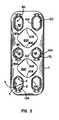
- FIG. 1is a plan view of a bone plate system including features in accordance with the present invention and securing vertebrae in a particular orientation;
- FIG. 2is a perspective view of the bone plate of FIG. 1 ;
- FIG. 3is plan view of the bone plate of FIG. 2 ;
- FIG. 4is a cross-sectional view of the bone plate system of FIG. 1 taken along the line 4 - 4 ;
- FIGS. 5A and 5Bare partial cross-sectional views of the bone plate with and without a retainer, respectively, located within a bore of the bone plate;
- FIG. 6is a plan view of a retainer
- FIG. 7is a side elevational of the retainer of FIG. 6 taken along the line 7 - 7 ;
- FIG. 8is a plan view of another retainer
- FIG. 9is a cross-sectional view of the bone plate system and a screw indicating insertion into the bone plate and a bone to which the bone plate system is to be secured;
- FIG. 10is a cross-sectional view of the bone plate system and screw of FIG. 9 with the screw partially inserted into the bone plate and bone;
- FIG. 11is a cross-sectional view of the bone plate system and screw of FIG. 9 with the screw fully inserted into the bone plate and bone;
- FIG. 12is a cross-sectional view of another retainer
- FIG. 13is a cross-sectional view of another retainer
- FIG. 14is a plan view of another retainer
- FIG. 15is a plan view of another retainer
- FIG. 16is a plan view of another embodiment of a bore plate system including a bone plate having a bore and a retainer located therein;
- FIG. 17is a plan view of another embodiment of a bore plate system including a bone plate having a bore and a retainer located therein;
- FIG. 18is a plan view of another embodiment of a bone plate system including a bone plate having a bore and a retainer located proximate thereof;
- FIG. 19is a plan view of another embodiment of a bone plate system including a bone plate having bores and a retainer located proximate thereof;
- FIG. 20is cross-sectional view of the bone plate and retainer of FIG. 19 taken along the line 20 - 20 ;
- FIG. 21is a plan view of a further embodiment of a retainer
- FIG. 22is a side elevational view of the retainer of FIG. 21 ;
- FIG. 23is an end view of the retainer of FIG. 21 ;
- FIG. 24is a second plan view of the retainer of FIG. 21 ;
- FIG. 25is a plan view of a further embodiment of a retainer
- FIG. 26is a side elevational view of the retainer of FIG. 25 ;
- FIG. 27is a plan view of a second form of the retainer of FIG. 25 ;
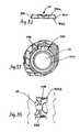
- FIG. 28is a plan view of a further embodiment of a bone plate
- FIG. 29is a side elevational view of the bone plate of FIG. 28 ;
- FIG. 30is a cross-sectional view of the bone plate of FIG. 28 taken through the line 30 - 30 ;
- FIG. 31is an end view of the bone plate of FIG. 28 ;
- FIG. 32is a cross-sectional view of the bone plate of FIG. 28 taken through the line 32 - 32 ;
- FIG. 33is a fragmentary cross-sectional view of the bone plate of FIG. 29 along the line 33 - 33 ;
- FIG. 34is a fragmentary cross-sectional view of a bore of the bone plate of FIG. 30 ;
- FIG. 35is a fragmentary bottom plan view of the bone plate of FIG. 28 ;
- FIG. 36is a fragmentary side elevation view of the bone plate of FIG. 29 ;
- FIG. 37is a plan view of a further embodiment of a bone plate similar to the bone plate of FIGS. 28-36 ;
- FIG. 38is a side elevational view of the bone plate of FIG. 37 ;
- FIG. 39is a cross-sectional view of the bone plate of FIG. 37 taken through the line 41 - 41 ;
- FIG. 40is an end view of the bone plate of FIG. 37 ;
- FIG. 41is side elevational view of a driver for use with bone plates, retainers, and screws;
- FIG. 42is a cross-sectional view of the driver of FIG. 41 ;
- FIG. 43is a fragmentary view in partial cross-section of the driver of FIG. 41 ;
- FIG. 44is a perspective view of a further embodiment of a bone plate
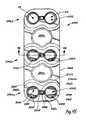
- FIG. 45is a top plan view of the bone plate of FIG. 44 showing three levels having non-dynamized bores and showing a retainer operating in a single hole and a retainer operating in a pair of holes of one of the levels;
- FIG. 46is an end elevational view of the bone plate of FIG. 44 showing a curvature in the lateral direction;
- FIG. 47is a side elevational view of the bone plate of FIG. 44 showing a curvature in the longitudinal direction;
- FIG. 48is a cross-sectional view of the bone plate taken through the line 48 - 48 of FIG. 45 ;
- FIG. 49is a cross-sectional view of the bone plate taken through the line 49 - 49 of FIG. 46 ;
- FIG. 50is a bottom plan view of the bone plate of FIG. 44 ;
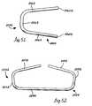
- FIG. 51is a top plan view of the retainer of FIG. 45 for operating in a single hole
- FIG. 52is a top plan view of the retainer of FIG. 45 for operating in a pair of holes;
- FIG. 53is a side elevation view of a bone plate fastener in the form of a self-drilling bone screw
- FIG. 54is a cross-sectional view of the bone screw of FIG. 53 ;
- FIG. 55is a cross-sectional view of a bone plate fastener in the form of a self-tapping bone screw
- FIG. 56is a side elevational view of a sizing tool for measuring portions of a spine
- FIG. 57is a cross-sectional view of the sizing tool taken through the line 57 - 57 of FIG. 56 ;
- FIG. 58is a fragmentary view of a distal end of the sizing tool
- FIG. 59is an exploded view of the sizing tool
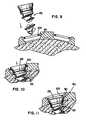
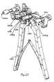
- FIG. 60is a perspective view of a bending tool for adjusting the shape of a bone plate in accordance with the present invention.
- FIG. 61is a second perspective view of the bending tool
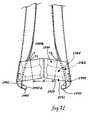
- FIG. 62is a front plan view of the bending tool
- FIG. 63is a perspective view generally of a front side of the bending tool taken from above thereof;
- FIG. 64is a perspective view generally of the front side of the bending tool taken from below thereof;
- FIGS. 66A and 66Bare partial exploded views of the bending tool
- FIG. 66is an exploded view of the bending tool
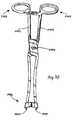
- FIG. 67is a perspective view of a holding tool for positioning the plate during implantation
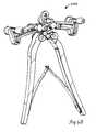
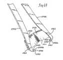
- FIG. 68is a fragmentary view of a side of a distal end of the holding tool showing recess for a drill guide for implanting a bone plate;
- FIG. 69is a second fragmentary view of a back side of the distal end of the holding tool.
- FIG. 70is a front elevational view of the holding tool
- FIG. 71is a third fragmentary view of a front side of the distal end of the holding tool showing the recess formed therein in phantom;
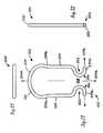
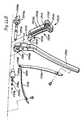
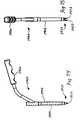
- FIG. 72is a side elevation view of a drill guide for directing cutting members
- FIG. 73is a cross-sectional view of the drill guide
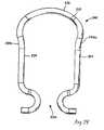
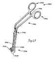
- FIG. 74is a side elevational view of an extractor tool for assisting in removal of bone anchors from an implanted bone plate;
- FIG. 75is a rear elevational view of the extractor showing retainer-shifting tines
- FIG. 76is a side elevational view of a holding pin for maintaining the position of a bone plate during implantation
- FIG. 77is a side elevational view of an awl for creating a pilot hole for implanting a bone plate, shown without corresponding gripping handle;
- FIG. 78is a side elevational view of a drill for opening a hole for implanting a bone plate, shown without corresponding gripping handle;
- FIG. 79is a side elevational view of a tap for providing threads in a hole for implanting a bone plate, shown without corresponding gripping handle;
- FIG. 80is a partially exploded view of a variable depth drill, shown without corresponding gripping handle;
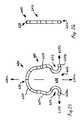
- FIG. 81is top plan view of a position ratchet of the variable depth drill taken through the line 81 - 81 of FIG. 80 ;
- FIG. 82is a top plan view of an embodiment of a four-tier bone plate.
- FIG. 83is a top plan view of an embodiment of a five-tier bone plate.
- the bone plate systemis a dynamized plate, or has at least one set of dynamic holes, so that bones 12 may compress and shift toward each other, such as the bone plate system 10 depicted in FIG. 1 .
- a bone plate system 700is illustrated as non-dynamized.
- a bone plate systemmay be provided including a bone plate where each bore thereof is dynamic, as is described herein, or non-dynamic, also described herein.
- a dynamized bone platemay utilize a combination of dynamic and non-dynamic bores.
- the bone plate system 10assists in the healing and repair of damaged, fractured, or broken bones 12 .
- the bones 12are adjacently located vertebrae of a spine, each spaced by a spinal disc 14 .
- the bone plate system 10may also be used, accordingly, to assist in the healing necessary after trauma has been experienced by the spinal disc 14 .
- the bone plate system 10may be utilized for stabilization and securement when adjacent vertebrae are fused, with or without the assistance of a bone graft between the vertebrae.
- the bone plate system 10is used to secure the bones 12 (and any prosthetic or graft) in a desired spatial relationship.
- the desired spatial relationship between the bones 12is generally vertical, such as the vertebrae would be in a normal, healthy spine when the person is standing.
- compression or loading of bonespromotes healing of the bones or bone fragments and improves the integrity of the fusion therebetween.
- the weight of the persondue to gravity, compresses those bones, such as a femur.
- the fusion of adjacent vertebraecan similarly benefit from using the weight of the person to compress the adjacent vertebrae.
- the dynamized bone plate system 10preferably allows the bones 12 to shift relative to each other.
- the bone plate system 10is designed to allow the bones 12 to compress in a manner dictated by the bone plate system 10 .
- the bone plate system 10includes a bone plate 20 secured to the bones 12 with bone anchors which are, in the preferred form, bone screws 22 each having a head 26 and a threaded shank 28 .
- the bone screws 22are preferably polyaxial for being driven into the bones 12 at an angle in relation to the plate desired by the surgeon or dictated by the surgical site. However, fixed angle screws, as described herein, may also be used.
- the plate 20preferably has a pair of bores 24 forming a tier and being located at each level at which a bone 12 or bone cement is to be secured thereto.
- the plate 20has an uppermost tier 30 , an intermediary tier 32 , and a lowermost tier 34 , each respectively in general proximity to an uppermost vertebrae 12 a , an intermediary 12 b vertebrae, and a lowermost vertebrae 12 c , where the plate 20 is utilized for securing the three vertebrae 12 a , 12 b , 12 c in a spatial relationship.
- any number of tierscould be provided for securing a plurality of bones, bone segments, or implanted materials.
- the plate 20is a dynamized or dynamic plate.
- the plate 20allows the bones 12 to compress towards each other by allowing at least a portion of the bone anchors in the form of screws 22 to shift relative to the plate 20 in a manner defined by the plate 20 .
- at least some of the bores 24are dynamized bores 40 .
- the bores 24 of the uppermost and lowermost tiers 30 , 34are dynamized bores 40
- the bores 24 of the intermediary tier 32are non-dynamized bores 42 such that the non-dynamized bores 42 permit either no or minimal shifting of the screw head 26 and shank 28 within and/or relative to the non-dynamized bore 42 .
- the uppermost bone 12 a secured by the dynamized bores 40 of the uppermost tier 30may translate toward the intermediary bone 12 b secured by the non-dynamized bores 42 of the intermediary tier 32 .
- the lowermost bone 12 c secured by the dynamized bores 40 of the lowermost tier 34 and the intermediary bone 12 b secured by the non-dynamized bores 42 of the intermediary tier 32may translate relatively toward each other, in which case both the uppermost bone 12 a and intermediary bone 12 b are jointly translating towards the lowermost bone 12 c .
- the plate 20may be equipped with two, or more, tiers 30 , 32 , 34 with each tier having non-dynamized bores 42 , or each tier having dynamized bores 40 , or any combination thereof, as desired.
- the plate 20may have four tiers (not shown) including an uppermost tier, a lowermost tier, and superior and inferior intermediary tiers, preferably with one of the intermediary tiers having non-dynamized bores, most preferably the inferior intermediary tier having non-dynamized bores.
- the amount of translation by the three bones 12 a , 12 b , 12 cis such that the uppermost and lowermost bones 12 a , 12 c translate relatively towards the intermediary bone 12 b the proper amount.
- the uppermost tier 30 , 32were provided with dynamized bores, the uppermost tier 30 would not only need to shift a distance towards the intermediary tier 32 , but would also need to shift more than the distance that the intermediary tier 32 shifts towards the lowermost tier 34 .
- the cumulative translation required for the uppermost tier 30is minimized in the present arrangement, which improves effectiveness and minimizes explantation or crushing of a fusion graft. Furthermore, the present arrangement creates better fixation between the plate 20 and the bones 12 by reducing respective moment arms between the screws 22 of the intermediary tier 32 and screws 22 of the uppermost and lowermost tiers 30 , 34 .
- the dynamized bore 40has an interior surface 50 with a racetrack, or oval, shape for receiving the screw head 26 where a lowermost portion 50 a of the interior surface 50 defines a racetrack-shaped throughbore 52 for receiving the screw shank 28 .
- a racetrack shaperefers to a shape with oppositely oriented arcuate portions joined by straight portions. Accordingly, when a screw 22 is located within the dynamized bore 40 and secured in a bone 12 , the screw 22 can shift towards the center (the intermediary tier 32 ) of the plate 20 due to compression of the bones 12 .
- the screw head 26can translate along the interior surface 50 , and the screw shank 28 can translate within the throughbore 52 , such translation being due to the weight of the erect person exerting a compression force along the spine.
- the interior surface 50 and throughbore 52define the path of translation or shifting for the screw 22 .
- the dynamized and non-dynamized bores 40 , 42have generally similar construction, with some notable differences.
- the non-dynamized bores 42have an interior surface 60 for receiving the screw head 26 , and the interior surface 60 has a lowermost portion 60 a defining a throughbore 62 for receiving the screw shank 28 .
- the interior surface 60 and lowermost portion 60 agenerally correspond to the interior surface 50 and lowermost portion 50 a of the dynamized bore.
- the interior surface 60 , lowermost portion 60 a , and throughbore 62 of the non-dynamized bore 42are not racetrack-shaped, instead being generally circular, so that the screw 22 received therein is not permitted to shift or translate relative to the plate 20 due to compression force on the spine when the screw is secured to the plate 20 and the bone 12 .
- the non-dynamized bores 42 and features thereof for receiving a screw 22are generally circular, while the dynamized bores 40 are elongated from a circle to have arcuate or circular ends with generally straight sections therebetween. Therefore, a lateral cross-section of a bore 24 , whether dynamized or non-dynamized, includes the same general features.
- FIG. 4A plate 20 with representative pairs of bores 24 and screws 22 located therein is depicted in FIG. 4 .
- Each bore 24has an inner surface 70 and a lowermost portion 70 a defining a throughbore 72 corresponding to the above described interior surfaces 50 , 60 , lowermost portions 50 a , 60 a , and throughbores 52 , 62 of the dynamized and non-dynamized bores 40 , 42 .
- the screw head 26secures against the inner surface 70
- the screw shank 28extends from the throughbore 72 and is secured within the bone 12 .
- a bridge or neck 27 portionconnects the head 26 to the shank 28 .
- Each portion of the screw 22other than helical threads of the shank 28 , is generally circular.
- the preferred screw 22is polyaxial so that the screw may be driven through the bore 24 at a selected angle. Accordingly, the screw head 26 is larger than the screw shank 28 and the throughbore 72 , and the screw shank 28 is smaller than the throughbore 72 .
- the inner surface 70has a brace surface 74 within which the bridge 27 of the screw 22 is positioned, the bridge 27 being smaller in diameter than the bore 24 within the brace surface 74 .
- the brace surface 74transitions to a seat surface 78 at a shoulder position 80 .
- the screw head 26rests against the shoulder position 80 , and the screw head 26 has an arcuate profile 82 that is able to seat properly against the shoulder 80 at the selected angle, as is depicted in FIG. 4 .
- the neck or bridge 27is sized relative to the bore 24 within the brace surface 74 to allow the proper amount of angulation for the screw 22 to be pivoted for a selected angle. That is, greater difference in diametral size of the neck 27 and the bore 24 within the brace surface 74 permits greater pivoting extent for the screw 22 located therein.
- the shoulder 80may have a number of constructions, such as simply an edge, or may be a chamfer, for instance.
- the seat surface 78is preferably larger in diameter than the screw head 26 to provide clearance so that the screw 22 may be mounted in a selected angle.
- the seat surface 78 and screw head 26may be spherical with closely matched diameters so that the screw head 26 may polyaxially slide against the seat surface 78 for driving the screw 22 in the bone 12 at the selected angle.
- the bone plate system 10includes anchor retainers 100 , and preferably a retainer 100 is provided for each bore 24 .
- a retainer 100is provided above the seat surface 78 .
- the screw head 26has a height H 1 that is less than a height H 2 of the seat surface 78 . The height differential between H 1 and H 2 allows the screw 22 to pivot a predetermined amount before the screw head top surface 29 interferes with the retainer 100 when it is pivoted.
- the top surface 29 of the screw 22is generally positioned below a lower edge 90 a of the recess 90 when the screw 22 is secured straight through the bore 24 , or is positioned below or generally coincident with the lower edge 90 a when the screw is secured at a selected pivoted angle.
- the inner surface 70has a receiving portion 92 that terminates at a top edge 21 meeting with a top surface 20 a of the plate 20 .
- each described portion of the inner surface 70is generally circular in shape.
- each described portion of the inner surface 70 for a dynamized bore 40is generally circular at the arcuate ends E and is straight for the straight sides S (see FIG. 3 ).
- each retainer 100is over top surface 29 of the screw head 26 such that the retainer 100 prevents the screw 22 from backing out through the bore 24 .
- the retainers 100are preferably preset in the plate 20 during the assembly process such that a surgeon can handle the plate 20 and retainers 100 as a single unit.
- the screws 22may be driven into the bones 12 to secure the plate 20 thereto, and the retainers 100 may then be inserted to prevent back-out of the screws 22 .
- FIG. 1the plate 20 is shown secured to bones 12 with screws 22 , and the screws 22 are prevented from backing out by the retainers 100 .
- FIGS. 6-8depict retainers 100 and, more particularly, depict a retainer 102 for a non-dynamized bore 42 (see FIG. 6 ) and a retainer 104 for a dynamized bore 40 (see FIG. 8 ).
- Each retainer 102 , 104has a closed end 110 , an open end 112 opposite the closed end 110 , and straights 114 located between the closed and open ends 110 , 112 .
- the retainer 100is held within the plate 20 by the recess 90 .
- the straights 114 of the retainer 100Prior to the screw 22 being inserted into the plate 20 , the straights 114 of the retainer 100 are positioned in a static position as is depicted in FIG. 9 . More specifically, the straights 114 extend through the bore 24 to interfere with the path of the screw head 26 to contact the seat surface 78 . As the screw 22 is driven into the bone 12 , the screw head 26 contacts the straights 114 , as is depicted in FIG. 10 . As the screw 22 continues into the bone 12 and plate 20 , the arcuate profile 82 of the screw head 26 cams against the straights 114 and forces, wedge-like, the straights 114 away from each other and into the recess 90 .
- the retainer 100generally returns to its static position such as that prior to insertion of the screw, as can be seen in FIG. 11 .
- the screw 22is, as discussed above, seated in the bone 12 and plate 20 such that the top surface 29 is generally below or approximately coincident with the lowermost edge 90 a of the recess 90 so that the retainer 100 held within the recess 90 is over the top surface 29 of the screw head 26 to prevent screw back out.
- the recess 90secures and holds the preset retainers 100 in the bores 24 .
- the closed end 110 of the retainerincludes two arms 120 joined by an elbow 122 that is slightly arcuate, though preferably with a smaller radius of curvature than the bores 24 .
- the open end 112includes two arms 121 each terminating with a leg 116 separated by a gap 118 .
- Each leg 116has a straight portion in the form of a foot 117 a , 117 b , aligned along an axis 117 c generally orthogonal to an axis 114 a of the straights 114 .
- the open end 112is compressed so that the legs 116 are brought together and the gap 118 therebetween is reduced or eliminated.
- the retainers 100are elastically resilient so that the closed end 110 may bend due to this compression, so that the open end 112 may be compressed and return to its natural shape when released, and so that the retainer 100 may expand and contract as the screw head 28 passes through and beyond the retainer 100 .
- the closed end 110is then inserted into the recess 90 , and the open end 112 is then inserted into a tab-shaped recess 96 , as depicted in FIGS. 5A and 5B .
- Each bore 40 , 42includes the tab-shaped recess 96 extending from the top surface 20 a of the plate 20 through the receiving portion 92 of the inner surface 70 of the bore 24 , and the tab recess 96 joins with the recess 90 .
- the tab recess 96allows the compressed legs 116 to be received in a portion of the recess 90 .
- a retainer pilot 98is provided as a bore for receiving the feet 117 of the retainer 100 .
- the retainer pilot 98may be drilled from a lateral side L of the plate 20 so that it is coincident with and through the tab recess 96 .
- the edges of the retainer pilot 98 , the tab recess 96 , and the recess 90 that are outboard from the bore 24are preferably aligned and coincident at a surface 99 .
- the left and right feet 117 a and 117 bare inserted in respective portions of the retainer pilot 98 a and 98 b for holding and securing the feet 117 therein so that the retainer 110 is secured within the bore 24 .
- the present embodiments of the retainers 102 , 104are described where the recess 90 extends around the entire periphery of the inner surface 70 of the bores 24 .
- the retainer pilot 98may be drilled into the lateral side L of the plate 20 and, therefore, has a circular cross-section. Accordingly, the feet 117 of the retainer 100 have a cross-sectional shape so that the feet 117 fit securely within the retainer pilot 98 . That is, the feet 117 should be sized, in cross-section, to slide in and out of the retainer pilot 98 while not having a significant amount of play or looseness so that the retainer 100 rests firmly in positions over the top surface 29 of the screw head 26 for preventing back-out.
- the entire cross-sectionis generally circular, as can be seen in FIG. 7 , so that the cross-section is substantially similar to that of the drilled retainer pilot 98 .
- the retainer 100need not have a uniform geometry such that the feet 117 and the straights 114 can have varying and/or different cross-sectional shapes.
- the retainer 100may have an alternative cross-sectional geometry, as depicted in FIGS. 12 and 13 , provided the feet 117 are properly fitted within the retainer pilot 98 .
- a retainer 130is depicted having straights 132 with arcuate surfaces 134 facing inward towards the opposite straight 132 .
- the arcuate surfaces 134allow the arcuate profile 82 of the screw head 26 to wedge the retainer 130 open when the screw 22 is being driven therethrough.
- the straights 132further have a generally flat bottom surface 136 that contacts the top surface 29 of a screw head 26 and provides resistance against screw back-out if the normal clearance between the retainer 130 and screw head 26 is breached.
- a retainer 140is illustrated having straights 142 with a chamfer or cam surface 144 facing inward towards the opposite straight 142 .
- the entire retainer 140may have the chamfer surface 144 .
- the chamfers 144allow the arcuate profile 82 of the screw head 26 to wedge the retainer 140 open when the screw 22 is being driven therethrough.
- the straights 142may have a generally flat bottom surface, such as depicted in FIG. 12 , or may have bottom surface 146 that rises from an inside edge 146 a to an outside edge 146 b .
- bottom surface 146is generally spaced above the top surface 29 of a screw head 26 when the retainer 140 and screw 22 are fully secured in a bone plate 20 .
- this bottom surface 146provides further resistance against screw back-out since the displaced screw back-out force will tend not to open the retainer to allow the spring to escape.
- the screw head top surface 29is preferably flat.
- a convex shapemay promote or assist screw back out as the convex head may force the retainer 100 open.
- a concave shapemay be employed for the top surface 29 , though such may decrease depth provided for a driver recess 26 a and, therefore, may make the screw head 26 more fragile when being driven.
- Closed-loop retainersmay be formed as a closed loop, such as by stamping, or may be a single length of material where the two ends are then joined, such as with butt-welding or crimping. Closed-loop retainers, as described herein, provide an additional benefit of more uniform expansion than the retainers with an open end because a greater portion of the spring deflects when a screw 22 is inserted.
- a closed-loop retainer 150includes oppositely located concave sections 152 , two straights 154 , and asymmetrical lobes 156 joining the concave sections 152 to the straights 154 .
- the arcuate profile 82 of the screw head 26may be driven against the straights 154 to force the retainer 150 open as the screw passes through, and the retainer 150 is resiliently elastic so that the retainer 150 generally returns to its undistorted shape after the screw head 26 has passed therethrough.
- the concave sections 152allow the closed loop to be elastically compressed to reduce its overall size or footprint so that it may be inserted and seated within a bore 24 .
- the bore 24may include the recess 90 , as discussed above.
- the recess 90is provided to hold the retainer 150 in place, and to do so needs to provide a receptacle or structure for securing the lobes 156 .
- the retainer 150has a larger longitudinal dimension A than lateral dimension B, such as is used with a dynamized bore 40 .
- the straights 154would be shorter so that the retainer 150 may be placed within a generally circular recess 90 .
- a retainer 160may be provided having four concave sections 162 to allow for resilient compression of the retainer 160 for insertion, resilient expansion for allowing the screw head 26 to pass therethrough, and resilient contraction after the screw head 26 has passed therethrough so that the retainer rests on the top surface 29 of the screw head 26 .
- the tab recess 96is not necessary.
- the boremay be generally square shaped.
- the plate 20has a bore 170 and a retainer 172 secured therein for resiliently expanding to permit a screw head 26 to pass therethrough and contracting once the screw head 26 has passed therethrough, and for resting over the top surface 29 of the screw head 26 .
- the retainer 172is generally V-shaped with portions 172 a , 172 b , and is located within a recess 174 formed in the bore 170 in a manner similar to that described above. However, the recess 174 may also be a depression formed in the top surface 20 a of the plate 20 .
- the retainer 172is staked or anchored by an anchor mount 176 located at the apex or bend 178 of the V-shape of the retainer 172 .
- the anchor mount 176holds the retainer 170 to the plate 20 , and may be a peg or pin inserted through the plate 20 .
- the retainer 172is forced open by the arcuate profile 82 of the screw head 26 as the screw 22 is being driven between the portions 172 a , 172 b of the V-shape. Once the screw 22 has passed through, the portion 172 a , 172 b generally return to their previous position to rest on the top surface 29 of the screw head 26 and to prevent screw back out.
- the bore 170is a non-dynamized bore, and the retainer 172 is structured accordingly.
- the bore 170would be elongated and the retainer 172 would be structured to complement the dynamized bore as has been discussed above.
- the plate 20has a bore 180 and a retainer 182 generally performing and being retained in the same manner as the bore 170 and retainer 172 .
- the bore 180is a dynamized bore
- the retainer 182is structured in a complementary fashion.
- the retainer 182is provided with two sets of opposed zig-zag arms 184 .
- the screw 22may be driven between these arms 184 in the same manner as for the straights of the retainers discussed above, or for the portions 172 a and 172 b for the V-shaped retainer 172 .
- the arms 184 of the retainer 182generally return to their previous position, as is discussed above.
- This retainer 182may also be formed as a closed loop like the retainer shown in FIG. 14 .
- FIG. 18Another form of a bone plate system 250 , as illustrated in FIG. 18 , includes a plate 252 having an uppermost tier 272 , an intermediary tier 274 , and a lowermost tier 276 , each tier having a pair of bores 24 and, in the preferred embodiment, the uppermost and lowermost tiers 272 , 276 having dynamized bores 240 , and the intermediary tier having non-dynamized bores 242 .
- the recess 90 discussed above for other embodimentsis unnecessary for the plate 252 , and, therefore, the bores 240 , 242 have a continuous inner surface 280 , 284 shaped for providing clearance for securing a polyaxial screw 22 at a selected angle (see FIG.
- the bores 240allow a screw 22 located therein to translate relative to the plate 252 , as described above, while the bores 242 do not permit such translation by a screw 22 located therein.
- the plate 252further include retainers in the form of a multi-bore retainer 290 which serves to impede screw back-out for more than one bore 240 , 242 simultaneously.
- the plate 252may include retainers in the form of a single-bore retainer 292 for impeding screw back-out for a single bore 24 , such as 240 , 242 .
- Each retainer 290 , 292is generally a wire or generally straight member with a static position crossing through the path of a screw 22 to be located within one of the bores 240 , 242 .
- the arcuate profile 82 of the screw head 26forces the retainer 290 , 292 to move away from the center of the bore 240 , 242 so that the screw head 26 may pass therethrough.
- the retainer 290 , 292returns to the static position so as to rest over the top surface 29 of the screw head 26 to prevent back-out thereof.
- the retainers 290 , 292are elastically resilient with minimal or no plastic deformation due to being deflected. That is, the retainers 290 , 292 elastically deform in order to be deflected from the static position, illustrated in FIG. 18 , to permit the screw head 26 to pass therethrough. Once the screw head 28 passes by the retainers 290 , 292 , the elasticity permits the retainers 290 , 292 to contract or return generally to the static position.
- the retainers 290 , 292may be a single filament wire with any cross-section. Alternatively, the retainers 290 , 292 may be a multi-filament, wound wire or a biocompatible polymeric material.
- the retainers 290 , 292deflect more easily in a direction generally along a top surface 252 a of the plate 252 than in a direction orthogonal to the top surface 252 a .
- a force applied by a screw 22 attempting to back out from the bore 240 , 242will force the retainers 290 , 292 outwardly from the plate 252 for the portion proximate to the screw head 26 .
- a retainer 290 , 292 of constant cross-section and constant materialwill deflect laterally due to the screw head 26 passing thereby, and the retainer 290 , 292 will equally deflect outward from the plate 252 when under equal force.
- the retainers 290 , 292may be provided with a structure so that the retainer 290 , 292 may deflect elastically an appropriate amount when the screw head 26 passes therethrough and so that the retainer 290 , 292 resists outward deflection when under stress.
- the retainer 290 , 292may have a first dimension in a lateral direction, represented by arrow ⁇ , and a greater dimension in the direction orthogonal to the plate top surface 252 a , that is, outwardly from the plate 252 . Accordingly, a greater force is required to deflect the retainer 290 , 292 outwardly, such as would happen from screw back-out, than is required to deflect the retainer 290 , 292 to permit passage of a screw head 26 .
- the retainers 290 , 292are generally located at or near the plate top surface 252 a .
- the retainers 290 , 292may be located on the plate top surface 252 a .
- the retainer 290 , 292may be entirely positioned within and below the plate top surface 252 a , may be partially positioned within the top surface 252 a , or may be within yet flush with the plate top surface 252 a . Accordingly, the top surface 252 a provides a excavated or depressed portion or region 252 b located proximate to the bores 240 , 242 such that the deflection of the retainer 290 , 292 is permitted though generally localized by a wall 252 c .
- the top surface 252 a of the plate 252may have a height in a region 252 d with respect to the top of the retainers 290 , 292 such that the top surface 252 a principally contacts the surrounding living tissues.
- the depression 252 bis formed, and the wall 252 c is formed between depression 252 b and the region 252 d .
- the wall 252 clocalizes the deflection of the retainer 290 , 292 while permitting the entire length of the multi-bore retainer 290 to stretch elastically to permit the screw 22 to be driven into the plate 252 .
- the retainers 290 , 292may be connected to the plate 252 in a variety of manners. For instance, it may be possible to simply glue the retainers 290 , 292 to the top surface 252 a . However, it is preferred that the retainers 290 , 292 are connected in a more mechanical manner.
- One manner for mounting the retainers 290 , 292is to provide a port or bore 301 in the plate for each end of the retainers 290 , 292 .
- the retainers 290 , 292may be fed into the port 301 from the top surface 252 a to a bottom surface (not shown) and tied or otherwise secured at the bottom surface.
- the retainers 290 , 292may be fed into the port 301 and soldered or welded into place, or crimped therein either by deformation directly at the port 301 or inward from a side of the plate, as represented by the arrow ⁇ .
- the plate 252may be provided with a physical structure (not shown) located on the top surface 252 a , the retainers 290 , 292 may be placed in the structure, and the retainers 290 , 292 may be secured in the structure either by deforming the structure or by adding another securing member, such as a clip or crimp for clamping the retainer 290 , 292 therein.
- a physical structurenot shown
- FIGS. 19 and 20a further embodiment of a retainer 400 and bone plate 402 is depicted.
- the plate 402has dynamized bores 404 and non-dynamized bores 406 .
- the number and orientation of the dynamized and non-dynamized bores 404 , 406may vary in the manner described for the above-discussed embodiments, and the retainer 400 may be utilized singly or in tandem with another similar retainer in conjunction with one or more bores 404 , 406 .
- the retainer 400may be constructed similarly to the retainers 290 , 292 , and may be a continuous loop such that the retainer passes over a bore, such as 404 , twice.
- the retainer 400is secured to the plate 402 by curved or undulating paths 410 .
- the paths 410are inset into the top surface 402 a of the plate 402 and are undercut at their lowest point 412 , as can be seen in FIG. 20 .
- Each pathhas preferably a first apex 416 , a second apex 418 , and a third apex 420 , such that the retainer 400 strung therein is captured.
- the ends 430 of the retainer 400may be captured or secured, as has been discussed above.
- a further embodiment of an retainer 500may be used with the bone plate 20 similar to the retainer 100 , as described above. More specifically, the retainer 500 may be in a plurality of forms, wherein a first form, depicted in FIGS. 21-24 , may be used with a dynamized bore 40 .
- the retainer 500includes two side portions 514 corresponding to the straights 114 of the retainer 100 .
- the length of the retainer 500may be increased, such as by increasing the length of side portions 514 , to provide various retainers corresponding to longer dynamized bores, depending on the amount of subsidence desired. Excepting the length, the various forms of the retainer 500 are generally identical in all other respects.
- Each retainer 500has a closed end portion 510 and an open end portion 512 opposite the closed end portion 510 .
- the retainer 500is held within the plate 20 by the recess 90 , and closed end portion 510 is received directly within the recess 90 .
- By decreasing the length of retainer 500it may be used with a non-dynamized bore, such as bore 42 .
- the straights 514 of the retainer 500are shaped as is depicted and are in a static position.
- the position within the bore 24 of the retainer 500is generally that as depicted in FIG. 9 for the retainer 100 .
- the side portions 514extend through the bore 24 to interfere with the path of the screw head 26 to contact the seat surface 78 .
- the screw head 26contacts the side portions 514 .
- the arcuate profile 82 of the screw head 26cams against the side portions 514 and forces the side portions 514 away from each other and into the recess 90 .
- the retainer 500generally returns to its static position, such as that prior to insertion of the screw. As discussed above, the screw 22 is seated in the bone 12 and plate 20 so that the retainer 500 is over the top surface 29 of the screw head 26 to prevent screw back out.
- the retainer 500is preset in the bores 24 .
- the closed end portion 510 of the retainer 500includes an arcuate segment 520 , though it could include arms 120 joined by the elbow 122 described above for retainer 100 .
- the arcuate segment 520provides a greater amount of the retainer 500 being received by the recess 90 , prospectively enhancing stability and securement to the retainer 500 within the plate 20 .
- the arcuate segment 520joins the side portions 514 . So that the side portions 514 are positioned to cross the bore 24 , ends 520 a of the arcuate segment 520 meeting with the side portions 514 are directed such that the arcuate segment 520 curves greater than 180 degrees. In other words, the arcuate segment 520 curves inward so that the side portions 514 have a narrower overall width for crossing the bore 24 .
- the side portions 514may be curved and/or skew to each other such that the distance between them increases as the side portions 514 extend away from the arcuate segment 520 , and, thus, the retainer 500 may be generally bowed-in.
- the open end portion 512includes two arms 521 each terminating with a leg 516 separated by a gap 518 .
- Each leg 516has a straight portion in the form of a foot 517 a , 517 b , aligned along an axis 517 c generally orthogonal to an axis 500 a of the retainer 500 .
- the retainer 500may be inserted within the bore 24 by compressing the open end portion 512 to bring the legs 516 together and reduce or eliminate the gap 518 .
- the closed end portion 510is then inserted into the recess 90 , and the open end portion 512 is then inserted into a tab-shaped recess 96 , as depicted in FIGS. 5A and 5B .
- the retainers 500are elastically resilient so that the retainer returns to its natural shape when released, and the retainer 500 may cooperate with the screw head 28 . Again, the securement and operation of the retainer 500 is similar to that of the retainer 100 , as described above.
- the retainer 500is depicted as generally circular in cross-section. Similar to the above discussion regarding, e.g., FIGS. 12 and 13 , the retainer 500 may have a non-uniform geometry, while the feet 517 a and 517 b are to be properly fitted within the retainer pilot 98 .
- the retainer 500may have upwardly facing arcuate surfaces corresponding to the arcuate surfaces 134 of retainer 130 in FIG. 12 to facilitate a cam-wedge action between the screw and the retainer 500 when the screw 22 is being driven therethrough.
- the retainer 500may also have downwardly facing flat surface corresponding to the bottom surface 136 of the retainer 130 for providing further resistance against screw back-out.
- the retainer 500may have a upward, inwardly facing chamfer surface corresponding to the cam surface 144 of retainer 140 in FIG. 13 .
- the retainermay also have a bottom surface corresponding to the bottom surface 146 , rising from an inside edge 146 a to an outside edge 146 b to provide further resistance against screw back-out.
- FIGS. 25-27forms of a further embodiment of a retainer 600 are depicted.
- the retainer 600is depicted in a first form 601 for use with a non-dynamized bore 42
- FIG. 27the retainer 600 is depicted in a second form 602 for use with a dynamized bore 40 .
- the retainer 600includes two side portions 614 corresponding to the straights 114 of the retainer 100 .
- the length of the retainer 600may be increased, such as by increasing the length of side portions 614 in the same manner side portions 514 of the retainer 500 may be increased, to provide retainers 600 with various lengths corresponding to dynamized bores providing for varying amounts of permitted subsidence.
- the various forms of the retainer 600are generally identical in all respects other than the lengths.
- Each retainer 600has a closed end portion 610 and an open end portion 612 opposite the closed end portion 610 . The retainer 600 is held within the plate 20 by the recess 90 , and closed end portion 610 is received within directly within the recess 90 .
- the retainer 600is depicted in a shape prior to insertion in the recess 90 .
- the position within the bore 24 of the retainer 600is generally that as depicted in FIG. 9 for the retainer 100 . That is, the side portions 614 are compressed so as to be generally parallel and to extend through the bore 24 to interfere with the path of the screw head 26 to contact the seat surface 78 .
- the screw head 26contacts the side portions 614 .
- the arcuate profile 82 of the screw head 26cams against the side portions 614 and forces the side portions 614 away from each other and into the recess 90 .
- the side portions 614return to the generally parallel position, and the screw 22 is seated so that the retainer 600 is over the top surface 29 of the screw head 26 to prevent screw back-out.
- the retainer 600is preset in the bores 24 .
- the closed end portion 610 of the retainer 600includes an arcuate segment 620 providing a greater amount being received by the recess 90 , prospectively enhancing stability and securement to the retainer 600 within the plate 20 .
- the arcuate segment 620joins the side portions 614 such that the retainer 600 is configured similarly to retainer 500 .
- the arcuate segment 620curves greater than 180 degrees, that is, curves inward, so that the side portions have a narrower overall width for crossing the bore 24 and for interfering with a seated screw 22 .
- the retainer 600has a geometry similar to retainers 100 and 500 . That is, the open end portion 612 has two arms 621 each terminating with a leg 616 separated by a gap 618 . Each leg 616 has a straight portion in the form of a foot 617 a , 617 b . When positioned within a bore 24 , the feet 617 a , 617 b are aligned along an axis 617 c generally orthogonal to an axis 600 a of the retainer 600 , and, as described, the straight portions 614 are generally parallel. However, as depicted, the retainer 600 is not inserted and, therefore, the feet 617 a , 617 b are not aligned along the axis 617 c . The retainer 600 may be inserted in to the recess 90 in the same manner as described above for retainers 100 and 500 .
- the retainer 600is depicted as generally circular in cross-section in FIG. 26 , the retainer 600 may have a non-uniform geometry, as described above for retainer 500 .
- FIGS. 28-40forms of a further bone plate 700 are depicted. More specifically, a bone plate 701 is depicted in FIGS. 28-36 , and a bone plate 702 is depicted in FIGS. 37-40 .
- the bone plates 701 and 702are generally identical in operation and features. However, the plate 701 is generally planar or flat, while plate 702 is curved, as can best be seen in comparing of FIG. 31 with FIG. 40 and in comparing FIG. 29 with FIG. 38 . The curvature of the plate 700 will be described in greater detail below.
- the plate 700is provided with representative pairs of bores 24 for receiving screws 22 .
- Each bore 24has an inner surface 770 and a lowermost portion 770 a defining a throughbore 772 corresponding to the above described interior surfaces 50 , 60 , 70 , lowermost portions 50 a , 60 a , 70 a , and throughbores 52 , 62 , 72 of the dynamized and non-dynamized bores 40 , 42 .
- the plate 700is depicted with non-dynamized bores 42 only, it should be noted that the plate 700 may also have dynamized bores 40 , with a geometry as described above for plate 10 .
- the plateis provided with two tiers of paired bores in the form of non-dynamized circular bores at one end and a pair of elongated dynamized bores at the other end.
- a three tier embodiment having a pair of dynamized bores at each end and non-dynamized bores in the middlemay also be provided.
- a four tier plate having a pair of dynamized bores sized for about 2 millimeters of movement along the spine axisis followed by circular non-dynamized holes, followed by dynamized holes sized for about 1.25 millimeters of movement, followed by a pair of dynamized bores sized for about 2.5 millimeters of movement as illustrated in FIG. 82 .
- Another possible embodimentconsists of a five tier plate with a pair of dynamized bores at the ends sized for 2.5 millimeters of movement, with adjacent pairs of dynamized bores sized for 1.25 millimeters of movement, and a pair of non-dynamized holes in the center as shown in FIG. 83 .
- the screw 22is preferably polyaxial and may be driven through the bore 24 at a selected angle. Therefore, the screw head 26 is larger than the screw shank 28 and the throughbore 772 , and the screw shank 28 is smaller than the throughbore 772 .
- the inner surface 770includes a brace surface 774 within which the bridge 27 of the screw 22 is positioned, the bridge 27 being smaller in diameter than the bore 24 within the brace surface 774 .
- the brace surface 774transitions to a seat surface 778 at a shoulder position 780 .
- the screw head 26rests against the shoulder position 780 , and the arcuate profile 82 of the screw head 26 seats against the shoulder 780 at the selected angle.
- the neck or bridge 27is sized relative to the bore 24 within the brace surface 774 to allow the proper amount of angulation for the screw 22 to be pivoted for a selected angle.
- the shoulder 780may have a number of constructions, such as simply an edge, or may be a chamfer, or the seat surface 778 and screw head 26 may be spherical with closely matched diameters so that the screw head 26 may polyaxially slide against the seat surface 778 for driving the screw 22 in the bone 12 at the selected angle.
- a retaineris preferably provided for each bore 24 .
- the plate 700may include a recess 790 above the seat surface 778 and extending around the inner periphery of the inner surface 770 . A portion of the retainer may be secured or located in the recess 790 .
- the screw head 26has height H 1 (see FIG. 4 ) that is less than a height H 3 of the seat surface 78 . The height differential between H 1 and H 3 permits the screw 22 to pivot a predetermined amount before the screw head top surface 29 interferes with the retainer when it is pivoted.
- the top surface 29 of the screw 22is generally positioned below a lower edge 790 a of the recess 790 when the screw 22 is secured straight through the bore 24 , or is generally coincident with the lower edge 790 a when the screw is secured at a selected pivoted angle.
- the inner surface 770has a receiving portion 792 that terminates at a top edge 721 meeting with a top surface 700 a of the plate 700 .
- each described portion of the inner surface 770is generally circular in shape, while for a dynamized bore 40 the inner surface 770 has straight sides, as described above.
- side edges 800 of the plate 700are angled inward from the bottom surface 700 b to the top surface 700 a . This reduces the profile of the plate and the likelihood of flesh becoming irritated from contact with the edges of the plate 700 in the lateral direction.
- the plate 700includes a tab shaped recess 796 , similar to tab recess 96 of plate 20 .
- the plate 700may include access ports 798 , as best seen in FIGS. 28 , 33 - 35 and 37 . More specifically, the access port 798 may be cut from the bottom surface 700 b towards the top surface 700 a to a depth coincident with the recess 790 .
- FIG. 33illustrates a bore 24 of the plate 700 with a portion removed laterally through the recess 790 such that the access port 798 is visible from a top view of the plate 700 .
- FIG. 28shows the plate 700 without the portion removed such that the access port 798 is partially obscured. A further comparison with FIG.
- FIG. 35shows the bottom side 700 b of the plate 700 such that the access port 798 is fully illustrated, and an interior top surface 799 of the recess 790 proximal to the tab recess 796 can be seen through the access port 798 (see also FIG. 34 ).
- the surgeonmay initially locate the bone plate 20 against the bones 12 .
- the bone plate 20includes windows 200 which permit viewing of a fusion site, such as a graft in place of a spinal disc 14 , located between the tiers 30 , 32 , 34 .
- the windows 200are preferably square or diamond shaped and oriented so that corners 202 are aligned with the longitudinal and lateral directions of the bone plate 20 .
- the windows 200may extend to a height and a width such that the extent of the permitted view therethrough includes a portion directly between the various bores 24 .
- the window 200may be an oval so that portions of the window 200 can provide a view located between the bores 24 , or any other shape.
- the windows 200extend so that ends 13 of the vertebrae 12 can be seen such that a surgeon can directly examine fusion sites at the ends 13 .
- a surgeonmay use radiography to view the fusion site without the plate 20 itself obscuring the view.
- the size of the window 200is predetermined and is based on the structural necessities of the plate 20 , such as the size, strength and fatigue life of the plate.
- each window 200may have a rib or extension spanning the window 200 .
- the ribmay include an additional bore for receiving a screw which may secure to a bone or an implant such as a graft.
- a window 200 amay be provided as is shown with plate 700 in FIG. 28 .
- the window 200 ahas an irregular shape including arcuate portions and straight portions such that the window 200 a is configured such as to not impede the structural integrity of the plate 700 while further attempting to maximize the view available therethrough to a surgeon.
- the bottom surface 20 b of the bone plate 20may include spikes or protrusions (not shown) for securing the bone plate 20 to at least one bone 12 .
- the non-dynamized bores 42are located on the intermediary tier 32 . Therefore, the bone plate 20 is not to shift relative to the middle bone 12 b with non-dynamized bores 42 .
- the protrusionsare provided on the bottom surface 20 b of the bone plate 20 in a region proximal to and contacting the middle bone 12 b .
- the spikes or protrusionsmay be provided between the bone plate 20 and any bone to which the plate 20 is not to shift relatively, that is, any bone secured to the plate 20 with non-dynamized bores 42 .
- the plate with spikesmay be manually pushed or tapped into the bone to secure the plate 20 thereto.
- the fixing of the plate 20 to a bone with bone anchors, such as screws 22 in the non-dynamized bores 42may force the spikes into that bone.
- the bone plate of the bone plate systemin its various embodiments, is often secured to bones or bone fragments 12 that have a curved surface facing the bone plates.
- the plates 20 , 700also have a curved or arcuate profile for following such a curved surface of the bone 12 .
- spinal vertebraeinclude characteristic bone protrusions (not shown) or randomly placed incongruities over which the bone plates would commonly be secured.
- the bone plates 20 , 700have one or more grooves or valleys 20 c , on the bottom surface 20 b , 700 b of the respective bone plates 20 , 700 .
- the bone platesmay include grooves or valleys oriented in any direction along the bottom surface 20 b , 700 b , for instance, of the plate.
- the bone 12may have a distinctly uneven surface, and the valley 20 c is provided so that localization of pressure at specific points between the bone 12 and the plate 20 , 700 is reduced or minimized, thus reducing the likelihood of bone necrosis.
- the valleys 20 care preferably formed so that the principal points of contact between the plate 20 , 700 and the bone 112 are controlled to be generally in the region of the bores 24 . Therefore, the positioned plate 20 , 700 may rest in a balanced position against the bones 12 and may tend to avoid rocking caused by an unbalanced or uneven positioning.
- FIGS. 44-52Illustrated in FIGS. 44-52 is a further form of a bone plate system 1000 including a bone plate 1002 and retainers 1004 for retarding the likelihood of backout by a bone screw 22 .
- the plate 1002includes bores 24 in the form of non-dynamized bores 1042 similar to bores 42 , the bores 1042 being paired in three transverse tiers 1006 a , 1006 b , 1006 c for securing to three vertebrae 12 a , 12 b , 12 c , as is depicted in FIG. 1 and described above.
- the bores 1042could alternatively be dynamized, with geometry similar to that described above for plate 10 .
- the plate 1002may be provided with only two tiers of bores 24 , or more tiers than three. As depicted, the plate 1002 includes windows 200 a as shown and described for plate 700 in FIG. 28 .
- the bores 24 of plate 1002have an inner surface 1010 and a lowermost portion 1012 defining a throughbore 1014 with a brace surface 1016 corresponding to the above described interior surface 60 , lowermost portion 60 a , throughbore 62 , and 74 of the non-dynamized bores 42 .
- the screw head 26secures against the inner surface 1010
- the screw shank 28extends from the throughbore 1014 for securing within the bone 12 .
- the cooperation between the screws 22 and the bores 24may be polyaxial or fixed, as has been described.
- a polyaxial screw 22may be inserted into the bone 12 at a desired angle relative to the plate 1002 , and the bridge 27 of the screw 22 is smaller in diameter than the bore 24 within the brace surface 1016 .
- a fixed screwmay be desired, which may include a screw shank 28 having a neck or bridge 27 having a substantially cylindrical shape that closely fits into and against the substantially cylindrical brace surface 1016 of the lowermost portion 1012 .
- the brace surface 1016forms a shoulder 1022 with a seat surface 1024 corresponding to the seat surface 778 and shoulder 780 of plate 700 .
- FIGS. 45 , 51 , and 52two similar forms of the retainer 1004 are depicted.
- FIG. 51depicts a preferred somewhat U-shaped retainer 1030 for being located within a single bore 24 to prevent backout of a single screw 22 located in the bore 24 .
- FIG. 52illustrates a retainer 1032 for preventing backout of a pair of screws 22 located in adjacent bores 24 , either of the same tier 1006 or spanning across tiers 1006 .
- the plate 1002presents the respective position of each retainer 1030 , 1032 , though it is expected that the plate 1002 is provided with one form of the retainer 1004 or the other.
- the retainers 1004are generally wire-like and have a cross-sectional geometry as described above.
- recesses 1040 for receiving the retainers 1004 and extending around the inner periphery of the inner surface 1010are included above the seat surfaces 1024 .
- at least a portion of the retainer 1004is positioned in the recess 1040 at a height greater than a height of the screw head 26 so that the difference between the heights permits the screw 22 to pivot a predetermined amount before the screw head top surface 29 interferes with the retainer 1004 , as has been described above.
- Non-dynamized bores 42may include a generally circular receiving portion 1044 , whereas the dynamized bores 40 may have generally straight sides, as described above.
- Each bore 24 of the plate 1002includes a recess 1050 , similar to the tab-shaped recess 796 described for plate 700 .
- the tab-shaped recesses 796are oriented generally along the longitudinal axis of the plate 700 .
- recesses for adjacent bores 24may be joined to form a single recess 1050 .
- the recesses 1050are laterally oriented so that a pair of bores 24 of the same tier 1006 are provided with the single recess 1050 .
- opposed tab walls 1052are formed extending transverse to the recess 1050 and having a gap 1054 therebetween.
- the gap 1054allows the retainers 1004 to be located in the plate 1002 .
- Retainer 1030includes a pair of arm portions 1060 and a bridge portion 1062 . In an unconstrained and natural position, the arms 1060 angle outward from the bridge 1062 .
- the retainer 1030is located in the recess 1040 so that the bridge 1062 is positioned within an outboard portion 1064 of the recess 1040 and central portions 1060 a of the arms 1060 extend across the bore 24 .
- terminal portions 1060 b and the arms 1060are elastically deflected inward and are passed through the gap 1054 between the tab walls 1052 . Once through the gap 1054 , the arms 1060 shift outward towards their natural position. Accordingly, the bridge 1062 may be positioned in the recess outboard portion 1064 , and the arm terminal portions 1060 b are positioned below the tab walls 1052 .
- the screw 22may be driven through the retainers 1030 and secured with the plate 1002 and bone 12 .
- the screw head 26contacts the central portions 1060 a , thereby forcing or camming the central portions 1060 a away from each other to permit the head 26 to pass between the arms 1060 .
- the arms 1060shift back toward each so that at least a portion of the arms 1060 is positioned above the top surface 29 of the screw 22 , thereby being positioned to restrict screw back-out.
- the retainer 1032operates is manner similar to that of retainer 1030 .
- the retainer 1032includes arms 1070 , two bridges 1072 connected to respective arms 1070 , and a connecting span 1074 between the bridges 1072 .
- the connecting span 1074is inserted through the gap 1054 and the arms 1070 are elastically deflected or compressed inward to force the retainer 1032 into the bores 24 .
- at least a portion of each bridge 1072is located in recesses 1040 of respective bores 24 , and the arms 1070 are located underneath one tab wall 1052 while the span 1074 is located underneath the opposed tab wall 1052 .
- Screws 22may be secured with the plate 1002 by driving them through the retainers 1032 located therein.
- the screw head 26being advanced into the plate 1002 contacts one of the arms 1070 and a portion of the span 1074 , elastically deflecting the arms 1070 and span portion 1074 outward to permit passing thereby.
- the arm 1070 and span portion 1074return inwardly toward each so that at least a portion of the each is positioned above the top surface 29 of the screw 22 , thereby being positioned to restrict screw back-out.
- the tab walls 1052are bent down to prevent the retainers 1030 and 1032 from escaping recess 1040 .
- Each of the bone platesis preferably made of biocompatible materials, such as titanium or titanium alloys, and stainless steels, or made of bioabsorbable materials, or made of a polymer, such as the polymer known as PEEK.
- the plateis formed from anodized titanium.
- the screw head 26includes a drive recess 300 .
- the drive recess 300is a hexagonal recess for receiving a driver 900 (see FIGS. 41-43 ) with, for example, a standard hex driving end 902 .
- a top portion 300 a of the drive recess 300is equipped with internal threads 302 with a large enough diameter that the driving end 902 may be inserted into the drive recess 300 with sufficient clearance of the internal threads 302 such that a sleeve 904 of the driver 900 may be threaded into the threads 302 with the driving end 902 located in the drive recess 300 .
- the sleeve 904may be utilized when a surgeon desires to remove the bone screw 22 .
- the screws 22may strip the threading made in the bone 12 . Therefore, the screw 22 must be removed and a new one inserted.
- the driving end 902may be inserted into the drive recess 300 and rotated, but the lack of purchase will prevent the driver 900 alone from removing the screw 22 . Therefore, the driving end 902 may be used to hold the screw 22 in a particular position, and the threaded sleeve 904 may be lowered and threaded into the top portion threads 302 , wherein the sleeve 904 may be used to extract the screw 22 .
- the sleeve 904may also be used at any time that there may be a concern about the screw 22 becoming disconnected from the driver 900 , such as insuring that the removed screw is not dropped into the surgical site.
- the driver 900includes a handle 910 connected to a driving shaft 912 that terminates in the driving end 902 that is received by the drive recess 300 . Accordingly, turning of the handle 910 when the driving end 902 is seated within the drive recess 300 effects rotation of the screw 22 .
- the driver 900also includes the sleeve 904 including external threads 920 at its distal end 922 for threading into the internal threads of the top portion 300 a of the drive recess 300 of the screw 22 , as described above.
- the sleeve 904is positioned closely about the driving shaft 912 .
- the sleeve 904 and driving shaft 912may shift relative to each other along the longitudinal axis 901 . That is, the sleeve 904 may be shifted relative to the driving shaft 912 in a distal direction such that the threads 920 of the sleeve 904 may be threaded into the drive recess 300 .
- the driving end 902will also be seated in the recess 300 .
- the sleeve 904 and driving shaft 912need to rotate relative to each other so that the driving shaft 912 is held stationary relative to the screw 22 .
- the sleeve 904 and driving shaft 912do not rotate relative to each other. Accordingly, the sleeve 904 is held in position around the driving shaft 912 with a bushing, such as a pair of rings 930 , 932 .
- the rings 930 , 932provide a frictional fit so that the driving shaft 912 and sleeve 904 may be rotated together, and provide for an adjustable position longitudinally and rotationally, as manual force can overcome the friction between the driving shaft 912 , sleeve 904 , and rings 930 , 932 .
- the sleeve 904may further include a grip 918 for manually holding or operating the sleeve 904 .
- a screw 22 to be implantedfirst receives the driving end 902 in the recess 300 .
- the sleeve 904is advanced to the recess 300 , and then screwed into the threaded portion 300 a .
- the screw 22is secured to the driver 900 .
- the screw 22is then driven into the bone by clockwise rotation.
- the sleeve 904is rotated counter-clockwise while the driving shaft 912 is held stationary. Once the sleeve 904 is freed from the recess 300 , the driving shaft end 902 is removed from the recess 300 .
- the stepsare simply reversed.
- the region 924 proximate to the distal end 922 of sleeve 904is tapered. As such, the region 924 is not substantially larger than the threads 920 of the sleeve 904 .
- the driver 900may further be used to shift the retainer to an open position such that the screw 22 may be extracted. Therefore, the region 924 may alternatively be sized to the diameter of the screw head 26 such the driver 900 may be used to shift the retainer to the open position for extracting the screw 22 .
- a separate toolsuch as in the form of an extractor 1900 ( FIGS. 74 , 75 ), may be used to shift the retainer to an open position.
- the extractor 1900may be used in conjunction with the driver 900 for removing screws. As shown in FIGS. 74 and 75 , the extractor 1900 includes a sleeve member 1902 with an elongated cavity 1904 therein, and a handle 1906 angled away from the sleeve member 1902 so that a surgeon may utilize the extractor 1900 without the handle 1906 obstructing the view. At a distal end 1910 of the extractor 1900 , a pair of prongs 1912 extends from the sleeve member 1902 . To remove the screws, the prongs 1912 may be placed within a retainer and then rotated so that each prong 1912 contacts a portion of the retainer to force the retainer to an open position.
- the driver 900While holding the retainer open with the extractor 1900 , the driver 900 may be inserted through the extractor cavity 1904 .
- the driving end 902 of the driveris received in the screw, and the external threads 902 of the driver sleeve 904 may be threaded into the screw head 26 so that the screw 22 may be easily and safely removed.
- the driver 900is then rotated or pulled to withdraw the screw 22 from the bone, and is finally removed.
- a self-drilling screw 1100is depicted in FIGS. 53 and 54 , and a self-tapping screw 1120 is depicted in FIG. 55 .
- Each screw 1100 , 1120has a shank 28 including threads 28 a , a head 26 , and a neck 27 therebetween.
- the self-drilling screw 1100includes a tip 1102 that is pointed and a cutting flute 1104 formed in the threads 28 a .
- the self-drilling screw 1100may be placed against a bone 12 , or in a pilot hole of a bone 12 , and advanced by forcibly driving the screw 1100 into the bone 12 .
- the cutting flute 1104forms a hole in the bone 12 as the screw 22 is advanced, and the threads 28 a cut into the bone 12 to form cooperating threads in the bone 12 .
- the self-drilling screws 1100are provided in a length short enough to prevent accidental driving of these sharper screw tips into sensitive tissues, such as nerves or blood circulatory passages.
- the self-tapping screw 1120is provided with a tip 1122 that is rounded and substantially dull.
- the screw 1120may be advanced into a pilot hole formed in the bone 12 , and the threads 28 a form cooperating threads in the bone 12 as the screw 1120 is forcibly driven into the bone 12 .
- the bone screws 22are preferably polyaxial for being driven into the bones 12 at an angle desired by the surgeon or dictated by the surgical site, or may be formed to provide a specific angle with the plate, these being referred to as fixed.
- the self-drilling screw 1100is polyaxial, and the self-tapping screw 1120 is a fixed screw. More specifically, screw 1100 has a neck 1127 a with a diameter D 1 , and screw 1120 has a neck 1127 b with a diameter D 2 .
- the bone platesare provided with a brace surface surrounding a lower portion of the bore, and the bore lower portion has a specific diametral size or, for a dynamized bore, a transverse size or distance across the bore lower portion. These sizes may be uniform for an individual plate, or different bores may be provided with different sizes.
- the screw necks 1127 a , 1127 bare, when secured in the plate, positioned within the bore lower portion 1012 .
- the diametral size of the bore 1012is larger than the screw neck diameter D 1 .
- the diametral size of the bore 1012is sized large enough only to permit the screw neck 1127 b with the diameter D 2 to be inserted therein and fit against the brace surface 1016 , in a peg and hole fashion.
- the fixed screw 1120is provided with an angle of insertion.
- rescue screwsmay be provided for securing in the bone.
- a rescue screwis a screw that has a larger thread diameter, or a larger central or minor diameter, or both. The rescue screw is able to gain purchase in the stripped hole, treating the it as if it were merely a pilot hole, by virtue of its larger size.
- a surgeonmay select from an array of bone plate systems.
- the number of bores and tiers in the platemay be chosen based on the number of vertebrae to be spanned.
- the boresmay be selected to be dynamized or non-dynamized depending on the amount of post-implantation compression desired.
- the screwsmay be fixed or polyaxial depending on the ability or desire for having a variable or fixed orientation or angle for the screw to be driven. For each of these choices, the surgeon may also select the actual size or dimensions of the plate, bores, and screws, typically determined by examining the vertebral portions to which the plate is to be secured.
- a plate sizer or sizing caliper 1200is utilized, as is shown in FIGS. 56-59 .
- the sizing caliper 1200includes a pair 1202 of legs adjustably positioned to align with points on one or more vertebrae to determine the proper distance for the screws 22 or the proper length of the plate required for the patient's anatomy.
- the pair 1202is composed of a measuring leg 1204 and a reference leg 1206 that has a sharp tip 1208 for being placed on a first desired location point on a vertebra.
- the location pointmay be a location for a bone screw 22 to be inserted thereat, or it could be a location defining the extent of one end of the bone plate itself.
- a pilot holemay be made in the vertebra, and the sharp tip 1208 may be placed in the pilot hole so that the position of the reference leg 1206 is more easily retained in place on the vertebra.
- the sizing caliper 1200is then adjusted by rotating a knob 1220 .
- This rotationcauses the measuring leg 1204 to move towards or away from the reference leg 1206 positioned at the first desired location point.
- the measuring leg 1204includes a ball-shaped tip 1210 so that it may move across the surface of the vertebra, for instance, with minimal catching on the surface or other tissue attached thereto.
- the position of the measuring leg 1204is adjusted until the ball tip 1210 is located at a second location point, which also may be a location for insertion of a bone screw 22 or a location defining the extent of a bone plate end.
- the measurement taken by the legs 1204 , 1206may then be compared directly to a plate, or may be compared to a scale.
- the sizing caliper 1200includes an elongate body 1230 with the knob 1220 located at a proximal end 1232 and the legs 1204 , 1206 generally secured at a distal end 1234 .
- the legs 1204 , 1206are secured together at a pivot point 1240 through which a pin 1242 is inserted to retain the legs 1204 , 1206 on the body 1230 .
- the knob 1220is rotated, the legs 1204 , 1206 shift position, either inward or outward depending on the direction of knob rotation, by pivoting around the pivot point 1240 .
- Both legs 1204 , 1206include a pivot arm 1256 that is outwardly angled in the proximal direction from the rest of the leg 1204 , 1206 such that force on a terminal end of the pivot arm 1256 causes the legs to rotate around the pivot point 1240 .
- the respective pivot arms 1256 a , 1256 b of the legs 1204 , 1206are angled away from each other and, when force is applied to both pivot arms 1256 a , 1256 b , the legs 1204 , 1206 pivot in opposite directions.
- the legs 1204 , 1206thus, operate in a scissors-like fashion.
- the pivot arms 1256are pivotally connected to a central reciprocating member 1260 . Movement of the reciprocating member 1260 in one direction causes the legs 1204 , 1206 to move towards each other, while movement in the other direction causes the legs 1204 , 1206 to move apart.
- the path of the reciprocating member 1260is defined by a channel 1209 in the body 1230 so that the path is generally linear.
- the reciprocating member 1260has a connection end 1261 pivotally attached to a proximal ends 1262 a of links 1262 , which are then pivotally attached at distal ends 1262 b to the outwardly angled pivot arms 1256 . Being attached to the connection end 1261 and to the outwardly angled pivot arms, the links 1262 are inwardly angled in the proximal direction. As the connection end 1261 moves towards the pivot point 1240 common to both legs 1204 , 1206 and the distance therebetween is decreased, the links 1262 attached to the connection end 1261 are further spread outward relative to each other. Conversely, when the connection end 1261 is retracted along with the reciprocating member 1260 , the links 1262 are drawn together to draw the legs 1204 , 1206 together.
- the reciprocating member 1260includes a proximal, drive end 1270 having a recess or cavity 1272 for receiving therein a drive end 1276 of a drive member 1274 .
- the cavity 1272includes a distal wall 1278 generally facing an end surface 1280 of the drive end 1276 .
- a bias or compression member 1282is located within the cavity 1272 in between the distal wall 1278 and the end surface 1280 .
- the reciprocating member cavity 1272is provided with a transversely oriented opening 1273 or rail for guiding the motion of the drive member 1274 .
- the drive member 1274is secured within the cavity 1272 by inserting a pin 1290 through the opening 1273 and through the drive member 1274 .
- the pin 1290interferes with a rear wall 1275 in the opening 1273 so that the reciprocating member 1260 is also retracted.
- the minimally invasive sizing caliper 1200may be utilized over a span of vertebrae for which the surrounding tissue is not completely removed or resected.
- the minimally invasive sizing caliper 1200as well as other instruments, preferably may access the implant site without requiring an opening in the patient as large as the implant site.
- the sizing caliper 1200may be directed into the patient opening, and the legs 1204 , 1206 may then be opened.
- the legs 1204 , 1206When the legs 1204 , 1206 are opened, they are often larger than the patient opening. So that the sizing caliper 1200 may be removed prior to comparing the caliper to, for instance, the distance between bores on a plate, the legs 1204 , 1206 may pivot to a smaller position as the caliper 1200 is being withdrawn. Once clear of the patient opening, the legs 1204 , 1206 return to the position they were in prior to removal and positioned at the vertebrae measuring points. This is achieved by use of the compression member 1282 . After the instrument is removed from the patient, it may be compared directly to the plates of different sizes or may be compared to a scale to determine the required plate size.
- the patient's fleshmay force the legs 1204 , 1206 together, or a surgeon may alternatively force them closed to ease removal of the caliper 1200 .
- the reciprocating member 1260in order to force the legs 1204 , 1206 together, the reciprocating member 1260 must retract towards the proximal end of the caliper 1200 .
- the compression member 1282in the form of a spring permits such retraction.
- the reciprocating member 1260compresses the spring 1282 against the drive member 1274 .
- the drive member 1274remains stationary so that, once the caliper 1200 is removed and the force applied to the legs 1204 , 1206 is relieved, the legs 1204 , 1206 return to the position in which they were when measuring the implant site. An accurate measurement may then be taken from the legs 1204 , 1206 .
- the knob 1220is rotated in one direction or the other, as previously noted.
- the knob 1220does not change position relative to the body 1230 , other than by rotating.
- the knob 1220includes an enlarged grip portion 1219 , and a shaft portion 1221 extending therefrom in the distal direction and received within the body 1230 . More specifically, the shaft portion 1221 is received by a bushing 1223 , and a snap ring or C-ring 1225 is secured to a distal end 1227 of the shaft portion 1221 to retain the shaft portion 1221 within the bushing 1223 .
- the grip portion 1219may be manually operated to rotate the knob 1220 relative to and within the bushing 1223 .
- a nut 1231 with a threaded exterior portion 1233 and an internal bushing surface 1235is located between a shoulder 1237 on the bushing 1223 and a shoulder 1239 on the grip portion 1219 .
- the threaded portion 1233is threaded into a threaded opening 1241 in the proximal end of the body. Accordingly, the nut 1231 is retained with a generally stationary position within the body 1230 . Furthermore, the nut 1231 between the shoulders 1237 , 1239 retains the knob 1220 in a position permitting rotation only.
- the drive member 1274is prevented from rotation by the pin 1290 received by the opening 1273 in the reciprocating member 1260 .
- the shaft portion 1221 of the knob 1220includes an inner threaded cylindrical bore 1251 into which the drive member 1274 is threadably received.
- the knob 1220also rotates relative to the drive member 1274 .
- the drive member 1274is threadably engaged with the knob 1220 , the threads therebetween cause the drive member 1274 to advance or retract relative to the knob 1220 , depending on the direction of rotation. Accordingly, the reciprocating member 1260 is advanced or retracted, and the legs 1204 , 1206 are opened or closed.
- Implantation of a bone plateis a relatively invasive procedure, and the bone plate residing in a living tissue environment contacts and interacts with that tissue.
- patients who have received bone plates on the anterior side of the cervical portion of the spinehave been known to physically feel the presence of the plate, particularly when swallowing. Accordingly, it is desirable to minimize the degree to which the bone plate interferes with the surrounding tissues.
- the structural performance of the bone platebenefits from conforming its shape to the natural curves of the spinal column.
- the lordotic curve of the spinal column and the lateral curve of each vertebraeis unique, though certainly within typical, somewhat predictable ranges.
- the cervical platemay be provided with a curvature in the longitudinal direction that is provided for the plate in order to conform the plate to the average natural lordotic curvature of the spine, as well as to reduce interference with surrounding tissues. It is often desirable to alter the standard shape of the plate to fit an individual patient's unique anatomy. This should be done in a manner so as not to scratch or mar the surfaces of the bone plate, which otherwise may negatively affect the long term fatigue performance of the bone plate.
- a plate bending instrument 1300is provided for altering the curvature of the plate when necessary due to a unique anatomy, a preferred form of which is illustrated in FIGS. 60-66 .
- the plate bender 1300is operated to either increase or decrease the radius of the lordotic curvature of the plate.
- the plate bender 1300is selectively operable so that a pair of opposed actuator handles 1331 , 1332 for bending the plate operate to impart a bending motion in a selected direction by directing the handles 1331 , 1332 towards each other.
- the plate bender 1300includes a pair of opposed arms 1310 , 1320 extending laterally from the handles 1331 , 1332 , and each of the handles 1331 , 1332 and arms 1310 , 1320 are operatively connected and pivotally secured at a pivot point 1375 a by a pin 1375 .
- the plate bender 1300includes engaging pegs or keys 1372 , 1382 that are selectively shiftable so that the each of the handles 1331 , 1332 are operatively engageable with either of the arms 1310 , 1320 .
- the opposed actuator handles 1331 and 1332are pivotally joined at an upper portion.
- the opposed lower gripping portions of the handles 1331 and 1332are biased outward from each other by a bias member in the form of attached springs 1335 and 1336 , which connect by insertion of tab 1337 into the mating slot 1338 of the spring 1336 .
- the springs 1335 and 1336are connected to the inward facing sides of handles 1331 and 1332 by rivets or by any other suitable means of attachment.
- Each handle 1331 , 1332respectively includes an upper shoulder portion including an extending flange 1333 , 1334 , and a central aperture 1333 a , 1334 a .
- the flanges 1333 and 1334are connected to the cylindrical pin 1375 which extends through the apertures 1333 a and 1334 a to provide a central pivot 1375 a for the handles 1331 and 1332 , and squeezing the handles 1331 , 1332 against the bias provided by springs 1335 , 1336 causes the flanges 1333 , 1334 and handles 1331 , 1332 to pivot about the pivot 1375 a.
- the first arm 1320includes a portion extending generally laterally from the central pivot 1375 a formed by opposed arm portions 1321 a and 1321 b , which define a central horizontally extending race 1322 .
- the arm 1320also includes an end portion 1323 which extends generally perpendicular to extending members 1321 a and 1321 b .
- Extending members 1321 a and 1321 bare preferably curved to match the standard anterior and posterior curvature of the cervical plate.
- the arm end portion 1323includes opposed side walls 1324 and 1325 defining a channel or a race 1326 oriented transverse to the race 1322 .
- the arm 1310includes a laterally extending portion including extending members 1311 a and 1311 b which define a race 1312 extending in the opposite direction of the race 1322 .
- the arm 1310includes an end portion 1313 formed from opposed sidewalls 1315 and 1314 which define the race 1316 extending generally perpendicular to the race 1312 .
- Each arm 1310 and 1320includes roller assemblies selectively positionable within races of the respective arms 1310 , 1320 .
- Each arm 1310 , 1320is provided with a convex roller assembly 1340 and a concave roller assembly 1350 .
- Each roller assemblyincludes a roller having a central longitudinal aperture and a pin mounted through the aperture on one side and to a knob connected to the pin on the backside of the instrument.
- convex roller assembly 1340 ais comprised of convex roller 1341 a which is positioned about its central aperture on the pin 1342 a and connected to the pin by a screw 1345 a through a washer 1346 a .
- a knob 1343 ais attached to the opposite end of the pin 1342 a by means of a connecting pin 1344 a , which extends through the knob 1343 a in a direction traverse to the longitudinal direction of the pin 1342 a and is retained by a shoulder at the end of the pin 1342 a . Loosening the knob 1343 a permits the convex roller assembly 1340 a to be positioned at any desired location within the race 1326 or the race 1322 .
- convex roller assemblies 1340 a , 1340 b and concave roller assemblies 1350 a and 1350 bare movably secured to the arms of the plate bending instrument 1300 in a corresponding manner.
- the roller assembliesare used in conjunction with one of two fulcra to adjust the curvature of the plate.
- the plate bender instrumentincludes a lower fulcrum 1370 extending frontward in the general direction of the central pivot access 1375 and an upper fulcrum 1306 also extending in the same direction.
- the lower fulcrum 1370has a convex bending surface 1370 a directed upward
- the upper fulcrum 1306has a concave bending surface 1306 a directed downward.
- the fulcra 1306 , 1370are connected to tool mount 1360 , and the upper fulcrum 1306 is selectively positionable upward and downward along a slot 1361 in the tool mount 1360 by a knob 1307 that may be loosened to allow the movement thereof and may be tightened to fix the selected position.
- the concave roller assembliesare used in combination with the lower fulcrum 1370 to increase the curvature of a plate, while the convex roller assemblies are used in with the upper fulcrum 1306 .
- the concave rollersmay apply a downward force to bend the plate about the fulcrum 1370 , as shown in FIG. 65 , thereby increasing the curvature of the plate when the tool 1300 is operated.
- the convex roller assemblies 1340 a and 1340 bmay be moved to the positions shown in FIG. 63 so as to not interfere with the bending operation.
- a plate placed between the convex rollers 1340 a , 1340 b and against the upper fulcrum 1306may be bent by the plate bender 1300 to decrease the curvature.
- Each roller and fulcrumhas a surface engageable with the plate that is covered by, and is preferably entirely formed of, a material that does not scratch or mar the plate during the bending operation, which otherwise may affect the fatigue life of the plate.
- the rollersare made with the polymer known as PEEK.
- PEEKpolymer known as polyethylene
- the arms 1320 , 1310include flange portions 1327 , 1317 also connected by the pivot pin 1375 and pivotable about the pivot point 1375 .
- the arms 1320 , 1310 and handles 1332 , 1331are joined at the common pivot point 1375 .
- the flange portions 1317 , 1327are in a generally facing relationship.
- Each flange portion 1317 , 1327has a pair of slots that are aligned with a counterpart of the other flange portion. That is, flange 1317 has a slot 1319 aligned with slot 1329 of the flange 1327 , and has a slot 1318 aligned with slot 1328 of the flange 1327 .
- the slots 1329 and 1319are aligned with a key slot 1372 a of the handle 1331 .
- the slots 1328 and 1318are aligned with a key slot (not shown) of the handle 1332 .
- the key slot 1372 ais aligned with the aligned arm slots 1329 , 1319 so that a key 1372 may be received in the key slot 1372 a and the arm slots 1329 , 1319 .
- the key 1372is shiftable from a position where the key 1372 is received in the key slot 1372 a and only one of the arm slots, such as 1329 , to a position where the key 1372 is received the key slot 1372 a and only the other arm slot 1319 .
- the handle 1331 and arm 1320behave as a unitary arm around the pivot point 1375 a .
- the handle 1331 and arm 1310pivot as a unit.
- the handle 1332operates in the same way as described, cooperating with the arm slots 1318 and 1328 .
- selector button 1393is secured to a barrel 1394 located in a throughbore 1372 b of the handle 1331 , and the barrel 1394 is then secured to selector button 1391 .
- the throughbore 1372 b and the key slot 1372 aare in communication so that a key recess 1394 a of the barrel 1394 located in the throughbore 1372 b may be accessed through the key slot 1372 a .
- the key 1372is inserted into the key slot 1372 b so that a portion is received in the barrel key recess 1394 a and a portion extends out of the key slot 1372 b for being received in one of the arm 1310 , 1320 , as discussed above.
- movement of one of the selector buttons 1393 , 1391selects which of the arms 1310 , 1320 with which the handle 1331 is joined.
- shifting the front selector button 1391 inwardshifts the barrel 1394 connected thereto through the throughbore 1372 b in the rearward direction, which causes the other button 1393 to also shift rearward.
- the shifting of the barrel 1394also causes the key 1372 to shift in the key slot 1372 a from the arm slots 1329 to the other arm slot 1319 .
- the handle 1331is disengaged from arm 1320 , and is engaged with arm 1310 .
- the handlesare cooperatively attached by the described slot-key configuration to one of the arms to form bending levers.
- the keys 1372 , 1382in a forward position, the handle 1331 and arm 1320 are connected to form a first opposed bending lever while the other handle 1332 is connected with the other arm 1310 to form a second opposed bending lever.
- the keys 1372 , 1382are in a rearward position, the handle 1331 and arm 1310 are connected to form a first crossing bending lever while the other handle 1332 is connected with arm 1320 to form a second crossing bending lever.
- the bending leversin any configuration, are connected by the pivot pin 1375 to pivot around pivot point 1375 a.
- the concave bending roller assemblies 1350 a , 1350 bare selectively positioned on the races towards the center of the plate bender 1300 in proximity to the lower fulcrum 1370 , as shown in FIG. 63 .
- a plateis then placed between the rollers 1351 a and 1351 b and the lower fulcrum 1370 with the top plate surface against the rollers 1351 a , 1351 b and the bottom plate surface against the lower fulcrum 1370 .
- the plate bender 1300As the plate bender 1300 is operated by directing the handles 1331 , 1332 inward, the arms 1310 , 1320 move downward toward the lower fulcrum 1370 so that the concave rollers 1351 a , 1351 b press the plate between the rollers 1351 a , 1351 and the lower fulcrum 1370 . In this manner, the plate is bent over the 1370 fulcrum to increase the curvature.
- the convex roller assemblies 1340 a , 1340 bare selectively positioned on the races and toward the center of the plate bender 1300 in proximity to the upper fulcrum 1306 .
- a plateis placed between the rollers 1341 a , 1341 b and upper fulcrum 1306 so that the top plate surface is against the upper fulcrum 1306 and the bottom plate surface is against the rollers 1341 a , 1341 b .
- the valleys 20 c of plate 20 , and plate 700includes valleys 700 d , as can be seen in FIGS. 28 and 37 , on the top surface 700 a to assist in bending the plate. These are meant to be exemplary only. These valleys 20 c , 700 d create stress concentrations to control or predict where the greatest amount of bending takes place, particularly in the event a surgeon chooses to manually adjust the shape of the bone plate.
- a plate holder 1400is used to hold the plate during implantation, and to hold a guide tool 1500 for positioning a pilot hole tool 1600 for creating a pilot hole in the vertebrae for the screws.
- the plate holder 1400is a scissors or forceps-type instrument having cooperating pivotable arms 1402 .
- the arms 1402have proximal ends 1404 including finger grips 1405 allowing a surgeon or the like to manipulate the plate holder 1400 .
- the arms 1402also have distal ends 1406 for connecting to the plate and for receiving the guide tool 1500 , as will be described below.
- the arms 1402are connected at a pivot point 1403 , and, when the proximal ends 1404 are directed towards each other, the distal ends 1406 also move towards each other.
- the proximal ends 1404also include opposed ratcheting bars 1408 so that, as the proximal ends 1404 move inwardly, the ratcheting bars 1408 catch each other. In this manner, once the plate holder 1400 is compressed on a plate, the ratcheting bars 1408 retain the position of the arms 1402 in the compressed position. To release the catch of the ratcheting bars 1408 , the arms 1402 are simply deformed or flexed slightly in a direction generally orthogonal to the plane of their pivotal movement.
- Each of the distal ends 1406 of the arms 1402includes a guide tool receptor 1420 for receiving the guide tool 1500 .
- the arms 1402are bent at a point between the pivot point 1403 and the proximal ends 1404 , and the guide tool receptors 1420 are attached to a side 1422 of each of the arms 1402 that is opposite the direction of the bend of the arms 1402 so that a surgeon's hand that is manipulating the finger grips 1405 does not obstruct the surgeon's view of the distal ends 1406 or the guide tool receptors 1420 .
- Each of the guide tool receptors 1420has a bottom surface 1424 , and terminal portions 1430 of each arm 1402 include opposed barbs or prongs 1440 .
- the bone plate 1002includes recesses 1450 for receiving and cooperating with the prongs 1440 .
- the plate 1002has a bottom surface 1452 and side edges 1454 , and a top surface 1456 .
- the recesses 1450are formed in pairs, each pair corresponding to a point along the plate 1002 that may receive the opposed prongs 1440 of the plate holder 1400 .
- the recesses 1450are generally formed to open to the side edges 1454 and the bottom surface 1452 . Accordingly, the recess 1450 has a upper surface 1458 generally facing downward. Thus, a wall 1460 is formed between the upper surface 1458 of the recess 1450 and the top surface 1456 of the plate 1002 .
- the top surface 1456may be provided with surface marks (not shown) that indicate where the recesses 1450 are located.
- the recess 1450has a structure and shape generally corresponding to the shape of the prongs 1440 .
- each prong 1440has a curved or arcuate top surface 1442 so as to be hemi-cylindrical.
- Each prong 1440also has a tip surface 1444 that may have the edges 1444 a rounded for ease of insertion into the recesses 1450 .
- the plate holder arms 1402may be pivoted to an open position such that the prongs 1440 are positioned at a distance greater than the lateral width of the plate 1002 .
- the prongs 1440are then aligned with a selected pair of recesses 1450 corresponding to a pair of bores 24 in the plate 1002 .
- the proximal ends 1404are then operated to direct the distal ends 1406 towards each other, and the prongs 1440 enter and fit closely within the recesses 1450 in the bone plate 1002 .
- portions 1462 of the arms 1402 proximate to the terminal portions 1430are angled inwardly. This inward angle allows the portions 1462 to cooperate with the prongs 1440 so that the wall 1460 partially defining the recess 1450 is securely held therebetween. Furthermore, the bottom surface 1424 of the guide tool receptors 1420 may contact the bone plate top surface 1456 to constrain any movement between the plate 1002 and the plate holder 1400 .
- each guide tool receptor 1420is configured to receive a guide tool 1500 .
- the guide tool 1500is used to direct a pilot hole tool 1600 into contact with a point on the vertebrae for forming a pilot hole thereon.
- the pilot hole tool 1600may be an awl 1620 , a drill 1630 , or a tap 1640 .
- pilot holemay mean a hole formed by compressing bone in a localized area as to make a recess in which a screw may find purchase, may be a hole formed by a rotating drill tip, or may be a hole formed by a tap such that the hole includes threads therein.
- the guide tool 1500may be provided for cooperating with a single guide tool receptor 1420 and pilot hole tool 1600 , or may be provided for cooperating with a pair of guide tool receptors 1420 and pilot hole tools 1600 .
- the guide tool receptor 1420includes a throughbore 1470 therethrough for receiving the guide tool 1500 and the pilot hole tool 1600 therein.
- the throughbore 1470has a central axis T, and the axes T 1 , T 2 of the pair of guide tool receptors 1420 for an included angle ⁇ that is, in the preferred embodiment, 18 degrees.
- Each throughbore 1470includes an upper portion 1480 , a lower portion 1482 , and a socket 1484 for cooperating with the guide tool 1500 .
- the guide tool 1500includes a distal end 1502 including a socket portion 1504 for cooperating with the socket 1484 of the guide tool receptor 1420 .
- the guide tool socket portion 1504is received in the throughbore 1470 so that, in a first form, the guide tool 1500 is fixed thereto and accepts a predetermined orientation so that its central longitudinal axis G is aligned and coincident with the axis T of the throughbore 1470 .
- the guide tool 1500may be received in the throughbore 1470 and be pivotable so that its axis G is offset from the throughbore axis T through a range, such as ⁇ 10 degrees in the direction of the longitudinal axis of the plate (cephalad/caudal direction) and ⁇ 5 degrees in the lateral direction.
- a pilot hole tool 1600is received within the guide tool 1500 and may be directed through a fixed guide tool 1500 along the longitudinal axis of the guide tool 1500 and the throughbore 1470 , or may be directed through a pivotable guide tool 1500 allowing the surgeon to make a selection as to the angle of entry by the pilot hole tool 1600 into the bone, and, thus, the angle of entry by a screw 22 subsequently inserted therein.
- the upper portion 1480 of the guide tool receptor socket 1484is angled radially outward, such as to be frusto-conical, so that the guide tool 1500 may pivot therein, and the lower portion 1482 is also angled radially outward as a frusto-cone so that a pilot hole tool 1600 received within a pivoted guide tool 1500 may pass through the throughbore 1470 to engage the bone at the angle dictated by the guide tool 1500 .
- the socket portion 1504 of the guide tool 1500includes a number of finger-like projections 1520 extending in a circular array from a distal end 1522 of a cannula member 1524 .
- the projections 1520include slot recesses 1526 therebetween so that the projections 1520 may be deflected inwardly.
- a terminal portion 1528 of each projection 1520includes an arcuate outer surface portion 1521 , and the combination of the portions 1521 combine so that the socket portion 1504 is generally ball-like.
- the socket 1484 of the guide tool receptor 1420has an inner surface 1484 a that is generally partially spheroidal, and the socket 1484 of the guide tool receptor 1420 and the guide tool socket portion 1504 form a ball-and-socket type connection, though with limited movement, as described above.
- the projections 1520are compressed or deflected inwardly so that the ball-shape socket portion 1504 is received within the spheroidal socket 1484 .
- the projections 1520 of the guide tool socket portion 1504are then permitted to deflect outward towards their natural position so that the arcuate surface portions 1521 thereof may contact the spheroidal inner surface 1484 a to form the ball-and-socket type joint.
- the projections 1520include an angled portion 1540 that angles radially outward from the cannula 1524 , increasing towards the distal end 1502 .
- the angled portion 1540has an edge 1548 at the point of its maximum dimension, which serves to form a shoulder 1549 on the projections generally facing the distal end 1502 .
- a sleeve 1530is utilized for camming against the angled portion 1540 to deflect the projections inward.
- the sleeve 1530is generally cylindrical and has an inner surface 1532 , an outer surface 1534 , a distal end 1536 , and a proximal end 1538 .
- the sleeve 1530may be reciprocated with respect to the guide tool cannula 1524 so that the inner surface 1532 cams against the angled portion 1540 between a first position in which the projections 1520 in a natural configuration, or are at least minimally deflected inwardly, and a second position in which the projections 1520 are deflected inwardly sufficient to allow the ball shape socket portion 1504 to be received within the socket 1484 of the guide tool receptor 1420 .
- the inner surface 1532 at the distal end 1532may contact a lower portion 1542 of the angled portion 1540 .
- the sleeve 1530may then be advanced so that the inner surface 1532 cams along the angled portion 1540 of the projections 1520 , thereby forcing the projections 1520 inward.
- the sleeve proximal end 1538includes a grip portion 1550 for manual manipulation of the sleeve 1530 relative to the cannula 1524 .
- the inner surface 1532includes an annular shoulder 1552 oriented generally in the distal direction.
- the cannula 1524has an inner surface 1554 that also includes an annular shoulder 1556 , though the shoulder 1556 is oriented generally towards the proximal end 1538 of the sleeve 1530 .
- the shoulders 1556 , 1552generally face each other, and a spring 1560 or other bias member is positioned between the shoulders 1556 , 1552 . In this manner, the sleeve 1530 is biased to the first position wherein the projections 1520 are generally undeflected, or are minimally so.
- the spring 1560is compressed against its bias.
- the cannula socket portion 1504is then inserted and located into the guide tool receptor socket 1484 , whereupon the sleeve 1530 may be retracted, such as by releasing the sleeve 1530 , by the bias of the spring 1560 .
- the projections 1520then shift outwardly toward their natural position within the socket 1484 .
- the projections 1520include the angled portion 1540 forming a shoulder 1549 generally facing the distal end 1502 .
- the movement of the guide tool 1500 relative to the socket 1484is dependent on the shoulder 1549 .
- the projections 1520assume a predetermined orientation within the socket 1484 , and, thus, the guide tool 1500 assumes a predetermined orientation.
- the variable angle guide tool 1500may be pivoted with respect to the socket 1484 within a range, such as defined above.
- the guide tool 1500orients and directs a pilot hole tool 1600 , as noted above. More specifically, the cannula 1524 of the guide tool 1500 receives and guides the pilot hole tool 1600 , as well as limits the depth to which the pilot hole tool 1600 may advance therewithin.
- pilot hole tools 1600 in the form of an awl 1620 , a drill 1630 , and a tap 1640are each formed as an elongate member having respective chuck or threaded ends 1650 , upper shoulders 1660 , shanks 1670 , lower shoulders 1680 , and driving end 1690 .
- the threaded end 1650is secured within an instrument for manual or powered operation.
- the pilot hole tool 1600is inserted into the cannula 1524 .
- the cannula 1524has an upper terminal edge 1570 , and the tool 1600 may be advanced until the upper shoulder 1660 contacts the terminal edge 1570 .
- the depth to which the tool 1600 may be driven into the boneis limited by the edge 1570 and the shoulder 1660 .
- the lower shoulder 1680is positioned around the tip 1690 so that the tool 1600 may be driven into the bone only to a depth provided by the length of the tip 1690 below the lower shoulder 1680 .
- the lower shoulder 1680is particularly provided in the event the tool 1600 is used without a guide tool 1500 .
- each of the tips 1690 of the respective awl 1620 , drill 1630 , and tap 1640is provided with a construction particular to its operation.
- the awl 1620has a pyramidal-shaped tip 1622 having flat faces that meet in sharp edges, similar to a nail.
- the awl 1620may, alternatively, have any pointed construction for being driven into bone to create a hole therein.
- the bonemay be compressed in the localized region of driving.
- the drill 1630includes a spirally fluted cutting bit 1632 , as is depicted. In this manner, the drill 1630 operates in the manner typical of drill bits or tips. As the bit 1632 rotates under pressure, a sharp terminal tip 1634 pierces the bone, and a fluted cutting edge 1636 widens the hole formed by the tip 1634 . The spiral configuration of the bit 1632 allows the drill 1630 to draw removed material out of the hole formed thereby.
- the tap 1640is inserted in a pilot hole that has already been made and is used for providing threads in the hole for receiving a screw therein.
- the tap 1640has a tip 1642 having threads 1644 along its length to the lower shoulder 1680 .
- a spiral flute 1646is provided across the threads along the length of the tip 1642 so that each thread 1644 is provided with a leading cutting edge.
- the threads 1644may also include an outer sharp edge along their major profile for cutting bone. Accordingly, as the tap 1640 is rotated and advanced into the screw hole, the flute 1646 and threads 1644 cut threads into the bone for the screw.
- variable pilot hole tool 1700is depicted.
- the tool 1700is a variable depth drill, though it may also be a tap, for instance.
- the variable drill 1700includes a threaded end 1702 , upper shoulder 1704 , a shank 1706 , a lower shoulder 1708 , and a driving end in the form of a fluted drill tip 1710 similar to the drill bit 1620 described above.
- the drill tip 1710may be longer than the drill bit 1620 described above so that the lower shoulder 1708 limiting the drilling depth is positioned a greater distance from a drill tip end 1712 .
- the upper shoulder 1704operates to contact the cannula upper edge 1570 when the drill 1700 has been advanced within the cannula 1524 to the desired depth.
- the upper shoulder 1704may be selectively positioned along a portion of the shank 1706 .
- the upper shoulder 1704is located on a housing 1720 that is, preferably, generally cylindrical.
- the housing 1720has an inner cylindrical cavity 1722 including an upper portion 1724 and a lower portion 1726 .
- the lower portion 1726has a reduced diameter in comparison to the diameter of the upper portion 1724 .
- a shoulder 1728is formed between the upper and lower portions 1724 , 1726 .
- the upper portion 1724includes an interior surface having a threaded portion 1744 .
- a threaded nut 1746may be inserted within the upper portion 1724 and have a threaded interior surface.
- the shank 1706is received within and through the housing 1720 . More specifically, the shank 1706 passes through a top opening 1760 and a bottom opening 1762 so that the threaded end 1702 is positioned above the top opening 1760 and the tip 1710 is positioned below bottom opening 1762 .
- the shank 1706includes an externally threaded portion 1750 so that the shank 1706 may be threaded into the threads 1744 of the housing 1720 .
- the shank 1706is rotated relative to the housing 1720 so that the threads 1744 , 1750 therebetween cooperate to advance or retract the shank 1706 with respect to the housing 1720 , thereby altering the amount of the shank 1706 extending below the bottom opening 1762 .
- the amount of shank 1706 that may be received in and through the guide tool 1500is adjusted by the rotation of the shank 1706 along the threads 1744 of the housing 1720 .
- a set screw 1780is provided for extending through the housing 1720 and into the lower cavity portion 1726 and, when advanced thereinto, the set screw 1780 contacts the shank 1706 to prevent movement of the shank 1706 relative to the housing 1720 .
- the housing 1720further includes a limiter 1790 for controlling the rotation of the shank 1706 relative to the housing 1720 .
- the shank 1706includes one or more grooves 1792 or recesses, and the limiter 1790 cooperates with the groove 1792 to regulate the relative rotation between the housing 1720 and the shank 1706 .
- the limiter 1790is fixed within the housing 1720 and includes a bias member 1794 that biases a protrusion in the form of a V-tab 1796 into engagement with the spline recess 1972 .
- a single groove 1792is provided, such that the V-tab 1796 engages the groove 1792 once for each rotation. In this manner, advancement of the shank 1706 relative to the housing 1720 is presented with discrete stops.
- the V-tab 1796is preferably biased into engagement with the groove 1792 by a bias member in the form of a spring 1794 .
- a bias memberin the form of a spring 1794 .
- rotation of the shank 1706will cause the V-tab to cam out of engagement in the groove 1792 .
- the spring 1794is relatively stiff, the V-tab 1796 does not allow rotation of the shank 1706 relative to the housing 1720 .
- the V-tab 1796is manually released.
- the V-tab 1796is secured on an inner surface 1798 of a limiter ring 1800 .
- the spring 1794biases the limiter ring 1800 so that the V-tab 1796 engages the groove 1792 .
- the spring 1974is located between an outer surface 1802 of the limiter ring 1800 and the interior 1719 of the housing 1720 .
- the V-tab 1796is manually released by forcing the limiter ring 1800 against the bias of the spring 1794 .
- An actuator button 1810is provided for disengaging the groove 1792 and V-tab 1796 .
- the actuator button 1810extending outward from the limiter ring 1800 and out through the housing 1720 .
- the limiter ring 1800is shifted against the spring 1794 , thereby shifting the V-tab 1796 out of the groove 1792 .
- the shank 1706may then be rotated for being advanced or retracted relative to the housing 1720 and for adjusting the depth the drill permitted into the bone.
- the variable drill 1700may be inserted into the guide tool 1500 , and a depth gage (not shown) may be used to confirm the proper drill depth.
- the sizing caliper 1200may be used to determine the proper plate size.
- the plateis selected based on dynamized bores, non-dynamized bores, or a combination.
- the plate bender 1300is used if it is desired to alter the curvatures of the plate.
- the types of screws 22are selected, whether they be fixed or variable angle (polyaxial) screws, and whether they be self-drilling, self-tapping, or neither so that a tap is minimally required.
- the plateis then grasped by the plate holder 1400 and positioned in the desired location on the vertebrae.
- a guide tool 1500is selected to be either fixed or variable, and then inserted into the guide tool receptors 1420 of the plate holder 1400 .
- a self-drilling screwmay be driven through the guide tool 1500 into the bone, or one or more pilot hole tools 1600 may be likewise used.
- a temporary holding pin 1850( FIG. 76 ) may be inserted through the guide tool 1500 to secure a hole made in the bone, or to create a hole in the bone.
- the temporary holding pin 1850has a threaded shank 1852 , and an enlarged head height 1854 so that the pin 1850 is clearly noticed as being temporary. In this manner, the plate may be secured so that the surgeon may address prepping other bone holes and driving screws through the other bores of the bone plate.
- a preferred sequence of inserting screws in the bores of the plateis presented. Each screw should not be completely tightened until all are partially secured. After a first bore has received a screw, the bore diagonal thereto receives the next screw. Next, the third bore to receive a screw is the bore on the same vertebrae as the first bore receives a screw. The fourth bore is diagonal to the third bore. Any intermediate bores may then receive screws. Once all the screws are in place, they should be tightened in the same order. To remove the screws, the extractor 1900 may be used in conjunction with the extractor 1900 .
Landscapes
- Health & Medical Sciences (AREA)
- Orthopedic Medicine & Surgery (AREA)
- Surgery (AREA)
- Life Sciences & Earth Sciences (AREA)
- Biomedical Technology (AREA)
- Public Health (AREA)
- Veterinary Medicine (AREA)
- Engineering & Computer Science (AREA)
- Nuclear Medicine, Radiotherapy & Molecular Imaging (AREA)
- Heart & Thoracic Surgery (AREA)
- Medical Informatics (AREA)
- Molecular Biology (AREA)
- Animal Behavior & Ethology (AREA)
- General Health & Medical Sciences (AREA)
- Dentistry (AREA)
- Oral & Maxillofacial Surgery (AREA)
- Neurology (AREA)
- Surgical Instruments (AREA)
- Prostheses (AREA)
Abstract
Description
Claims (17)
Priority Applications (6)
| Application Number | Priority Date | Filing Date | Title |
|---|---|---|---|
| US10/973,891US7740649B2 (en) | 2004-02-26 | 2004-10-26 | Bone plate system and methods |
| PCT/US2005/038537WO2006047581A2 (en) | 2004-02-26 | 2005-10-26 | Bone plate system and methods |
| US11/259,714US7909859B2 (en) | 2004-02-26 | 2005-10-26 | Bone plate system and methods |
| US13/069,354US8900277B2 (en) | 2004-02-26 | 2011-03-22 | Bone plate system |
| US14/554,960US10166051B2 (en) | 2004-02-26 | 2014-11-26 | Bone plate system |
| US16/217,652US11129653B2 (en) | 2004-02-26 | 2018-12-12 | Bone plate system |
Applications Claiming Priority (2)
| Application Number | Priority Date | Filing Date | Title |
|---|---|---|---|
| US54814004P | 2004-02-26 | 2004-02-26 | |
| US10/973,891US7740649B2 (en) | 2004-02-26 | 2004-10-26 | Bone plate system and methods |
Related Child Applications (1)
| Application Number | Title | Priority Date | Filing Date |
|---|---|---|---|
| US11/259,714Continuation-In-PartUS7909859B2 (en) | 2004-02-26 | 2005-10-26 | Bone plate system and methods |
Publications (2)
| Publication Number | Publication Date |
|---|---|
| US20050192577A1 US20050192577A1 (en) | 2005-09-01 |
| US7740649B2true US7740649B2 (en) | 2010-06-22 |
Family
ID=34890541
Family Applications (2)
| Application Number | Title | Priority Date | Filing Date |
|---|---|---|---|
| US10/973,891Expired - Fee RelatedUS7740649B2 (en) | 2004-02-26 | 2004-10-26 | Bone plate system and methods |
| US11/259,714Active2028-09-03US7909859B2 (en) | 2004-02-26 | 2005-10-26 | Bone plate system and methods |
Family Applications After (1)
| Application Number | Title | Priority Date | Filing Date |
|---|---|---|---|
| US11/259,714Active2028-09-03US7909859B2 (en) | 2004-02-26 | 2005-10-26 | Bone plate system and methods |
Country Status (2)
| Country | Link |
|---|---|
| US (2) | US7740649B2 (en) |
| WO (1) | WO2006047581A2 (en) |
Cited By (34)
| Publication number | Priority date | Publication date | Assignee | Title |
|---|---|---|---|---|
| US20070250061A1 (en)* | 2006-04-24 | 2007-10-25 | Spinefrontier Lls | Spine fixation method and apparatus |
| US20090131988A1 (en)* | 2007-11-09 | 2009-05-21 | Stryker Spine | Cervical plate with a feedback device for selective association with bone screw blocking mechanism |
| US20090287257A1 (en)* | 2008-05-16 | 2009-11-19 | Hagen Leslie | Cervical plate |
| US20110137344A1 (en)* | 2003-09-03 | 2011-06-09 | Rathbun David S | Bone plate with captive clips |
| US20120150236A1 (en)* | 2003-10-22 | 2012-06-14 | Paul Kamaljit S | Bone repair systems |
| US20130053887A1 (en)* | 2011-08-26 | 2013-02-28 | Life Spine, Inc. | Bone Screw Retention in a Spinal Implant |
| US8419776B2 (en) | 2010-03-08 | 2013-04-16 | Memometal Technologies | Radius-plate assembly |
| US8579898B2 (en) | 2010-03-08 | 2013-11-12 | Memometal Technologies | Adjustable-angle radius plate |
| US8784459B2 (en) | 2012-01-17 | 2014-07-22 | Genesys Spine | Spinal plate and locking screw devices, methods, and systems |
| US8900277B2 (en) | 2004-02-26 | 2014-12-02 | Pioneer Surgical Technology, Inc. | Bone plate system |
| WO2015035268A1 (en)* | 2013-09-06 | 2015-03-12 | Thomas Jefferson University | Angled craniotome and minimal plating system for improved cosmesis and structural integrity of craniotomies |
| US9101426B2 (en) | 2012-10-11 | 2015-08-11 | Stryker Trauma Sa | Cable plug |
| US9101407B2 (en) | 2011-07-19 | 2015-08-11 | Howmedica Osteonics Corp. | Anterior cervical plate |
| US9220548B2 (en) | 2003-09-03 | 2015-12-29 | DePuy Synthes Products, Inc. | Bone plate with captive clips |
| US9271742B2 (en) | 2012-08-09 | 2016-03-01 | Wilson Theophilo Asfora | System for joint fusion |
| US9414870B2 (en) | 2003-09-03 | 2016-08-16 | DePuy Synthes Products, Inc. | Translatable carriage fixation system |
| US9468479B2 (en) | 2013-09-06 | 2016-10-18 | Cardinal Health 247, Inc. | Bone plate |
| US20160324552A1 (en)* | 2014-01-08 | 2016-11-10 | Smith & Nephew, Inc. | Drill guide system and method |
| US9801671B2 (en) | 2013-07-11 | 2017-10-31 | Stryker European Holdings I, Llc | Fixation assembly with multiple sections for securing parts of a sternum |
| US9839463B2 (en) | 2012-09-06 | 2017-12-12 | Stryker European Holdings I, Llc | Instrument for use in bending surgical devices |
| US9913672B2 (en) | 2014-05-28 | 2018-03-13 | Genesys Spine | Resiliant spinal plate system |
| US9943341B2 (en) | 2013-07-16 | 2018-04-17 | K2M, Llc | Retention plate member for a spinal plate system |
| US10064741B2 (en) | 2015-12-28 | 2018-09-04 | Titan Spine, Inc. | Clamping device for affixing a stop plate to an interbody implant |
| US10499968B2 (en) | 2014-08-08 | 2019-12-10 | Stryker European Holdings I, Llc | Cable plugs for bone plates |
| US11234742B2 (en)* | 2017-11-16 | 2022-02-01 | Globus Medical, Inc. | Anterior cervical plate assembly |
| US11259937B2 (en)* | 2018-11-09 | 2022-03-01 | Shanghai Chanczheng Hospital | Cervical vertebra fixing plate maintaining natural height, cervical vertebra anterior fixation and fusion system maintaining natural height and method thereof |
| US11259853B2 (en) | 2015-01-09 | 2022-03-01 | Stryker European Operations Holdings Llc | Implant for bone fixation |
| US11304817B2 (en) | 2020-06-05 | 2022-04-19 | Neurostructures, Inc. | Expandable interbody spacer |
| US11382761B2 (en) | 2020-04-11 | 2022-07-12 | Neurostructures, Inc. | Expandable interbody spacer |
| US11596458B2 (en) | 2016-11-11 | 2023-03-07 | Stryker European Operations Holdings Llc | Implant for bone fixation |
| US20230202007A1 (en)* | 2016-08-19 | 2023-06-29 | Peter Witte | Torque limiter |
| US11717419B2 (en) | 2020-12-10 | 2023-08-08 | Neurostructures, Inc. | Expandable interbody spacer |
| US11801081B2 (en) | 2021-11-04 | 2023-10-31 | Warsaw Orthopedic, Inc. | Surgical instrument and method |
| US11877779B2 (en) | 2020-03-26 | 2024-01-23 | Xtant Medical Holdings, Inc. | Bone plate system |
Families Citing this family (169)
| Publication number | Priority date | Publication date | Assignee | Title |
|---|---|---|---|---|
| US6755833B1 (en) | 2001-12-14 | 2004-06-29 | Kamaljit S. Paul | Bone support assembly |
| US7070599B2 (en) | 2002-07-24 | 2006-07-04 | Paul Kamaljit S | Bone support assembly |
| US7811312B2 (en)* | 2002-12-04 | 2010-10-12 | Morphographics, Lc | Bone alignment implant and method of use |
| US8172885B2 (en) | 2003-02-05 | 2012-05-08 | Pioneer Surgical Technology, Inc. | Bone plate system |
| KR100552117B1 (en)* | 2003-07-22 | 2006-02-13 | 유앤아이 주식회사 | Cervical vertebrae device and driver used in it |
| US7306605B2 (en) | 2003-10-02 | 2007-12-11 | Zimmer Spine, Inc. | Anterior cervical plate |
| US8182485B1 (en) | 2003-11-21 | 2012-05-22 | Toby Orthopaedics, Llc | Fracture fixation system |
| US7740649B2 (en) | 2004-02-26 | 2010-06-22 | Pioneer Surgical Technology, Inc. | Bone plate system and methods |
| DE102004043700A1 (en)* | 2004-09-09 | 2006-03-16 | Plus Endoprothetik Ag | Endoprosthesis for a metatarsophalangeal joint |
| WO2006058221A2 (en) | 2004-11-24 | 2006-06-01 | Abdou Samy M | Devices and methods for inter-vertebral orthopedic device placement |
| US7799061B2 (en) | 2005-01-28 | 2010-09-21 | Orthohelix Surgical Designs, Inc. | Orthopedic plate |
| US8118846B2 (en)* | 2005-01-28 | 2012-02-21 | Orthohelix Surgical Designs, Inc. | Orthopedic plates for use in clavicle repair and methods for their use |
| WO2006096273A2 (en)* | 2005-03-03 | 2006-09-14 | Accelerated Innovation, Llc | Methods and apparatus for providing a retainer for a bone stabilization device |
| US7481811B2 (en)* | 2005-03-11 | 2009-01-27 | Synthes (U.S.A.) | Translational plate with spring beam retainer |
| US8016887B1 (en)* | 2005-03-24 | 2011-09-13 | Cardinal Spine, Llc | Spinal implant with overlay |
| US7452370B2 (en)* | 2005-04-29 | 2008-11-18 | Warsaw Orthopedic, Inc | Apparatus for retaining a bone anchor in a bone plate and method for use thereof |
| US8070749B2 (en) | 2005-05-12 | 2011-12-06 | Stern Joseph D | Revisable anterior cervical plating system |
| WO2006124273A2 (en)* | 2005-05-12 | 2006-11-23 | Stern Joseph D | Revisable anterior cervical plating system |
| DE112006002765A5 (en)* | 2005-09-01 | 2008-09-04 | Merete Medical Gmbh | Bone plate with at least one screw for angular stable fixation |
| US20070093834A1 (en)* | 2005-10-06 | 2007-04-26 | Stevens Peter M | Bone alignment implant and method of use |
| WO2007056516A2 (en)* | 2005-11-09 | 2007-05-18 | Abdou M S | Bone fixation systems and methods of implantation |
| US9119677B2 (en) | 2005-12-09 | 2015-09-01 | DePuy Synthes Products, Inc. | Spinal plate and drill guide |
| US20070233108A1 (en)* | 2006-03-15 | 2007-10-04 | Stalcup Gregory C | Spine fixation device |
| US7951178B2 (en)* | 2006-04-03 | 2011-05-31 | Acumed Llc | Bone plates with hybrid apertures |
| CA2648444C (en)* | 2006-04-04 | 2014-03-18 | Smith & Nephew, Inc. | Trial coupler systems and methods |
| US10085780B2 (en) | 2006-05-26 | 2018-10-02 | Mark Richard Cunliffe | Bone fixation device |
| US20120029576A1 (en)* | 2006-05-26 | 2012-02-02 | Mark Richard Cunliffe | Bone Fixation Device |
| US7776070B2 (en)* | 2006-08-02 | 2010-08-17 | Warsaw Orthopedic, Inc. | Occipital plating systems and methods |
| WO2008034140A2 (en)* | 2006-09-15 | 2008-03-20 | Pioneer Surgical Technology, Inc. | Systems and methods for sizing, inserting and securing an implant intervertebral space |
| US8715350B2 (en) | 2006-09-15 | 2014-05-06 | Pioneer Surgical Technology, Inc. | Systems and methods for securing an implant in intervertebral space |
| US8361130B2 (en) | 2006-10-06 | 2013-01-29 | Depuy Spine, Inc. | Bone screw fixation |
| US8262710B2 (en)* | 2006-10-24 | 2012-09-11 | Aesculap Implant Systems, Llc | Dynamic stabilization device for anterior lower lumbar vertebral fusion |
| US20080114457A1 (en)* | 2006-11-14 | 2008-05-15 | Warsaw Orthopedic, Inc. | Methods and devices for connecting implants and devices |
| US20130012945A1 (en)* | 2006-11-21 | 2013-01-10 | Smith & Nephew, Inc. | Variable drill guide |
| US20090030466A1 (en)* | 2007-01-31 | 2009-01-29 | Strauss Kevin R | Anterior vertebral plate with suture lock |
| US8636779B2 (en)* | 2007-02-26 | 2014-01-28 | Life Spine, Inc. | Spine plate with configured bone screw bores |
| US8702762B2 (en) | 2007-03-27 | 2014-04-22 | Depuy Spine, Inc. | Passive screw locking mechanism |
| US20080249569A1 (en)* | 2007-04-03 | 2008-10-09 | Warsaw Orthopedic, Inc. | Implant Face Plates |
| US8425607B2 (en)* | 2007-04-03 | 2013-04-23 | Warsaw Orthopedic, Inc. | Anchor member locking features |
| US8268000B2 (en)* | 2007-04-03 | 2012-09-18 | Warsaw Orthopedic, Inc. | Composite interbody spacer |
| US8257395B2 (en)* | 2007-09-21 | 2012-09-04 | Jmea Corporation | Spinal fixation with selectively applied bone growth promoting agent |
| US20090048675A1 (en)* | 2007-04-25 | 2009-02-19 | Bhatnagar Mohit K | Spinal Fusion Implants with Selectively Applied Bone Growth Promoting Agent |
| US8361126B2 (en) | 2007-07-03 | 2013-01-29 | Pioneer Surgical Technology, Inc. | Bone plate system |
| US8623019B2 (en) | 2007-07-03 | 2014-01-07 | Pioneer Surgical Technology, Inc. | Bone plate system |
| US8317843B2 (en)* | 2007-07-11 | 2012-11-27 | Perumala Corporation | Multi-axis connection and methods for internal spinal stabilizers |
| US8343194B2 (en)* | 2007-08-20 | 2013-01-01 | Kamran Aflatoon | Anterior cervical staple |
| US20110319943A1 (en) | 2007-08-20 | 2011-12-29 | Ryan Donahoe | Surgical Fixation System and Related Methods |
| US8388663B2 (en) | 2007-09-13 | 2013-03-05 | Stryker Spine | Dynamic cervical plate |
| US8852280B2 (en) | 2007-09-27 | 2014-10-07 | Warsaw Orthopedic, Inc. | Intervertebral implant |
| US8613761B2 (en)* | 2007-09-28 | 2013-12-24 | Warsaw Orthopedic, Inc. | Surgical implant with an anti-backout feature |
| US8496693B2 (en)* | 2007-10-16 | 2013-07-30 | Amendia Inc. | Bone screw retaining and removal system |
| EP2224868B1 (en)* | 2007-11-21 | 2014-07-30 | Globus Medical, Inc. | Cervical spine stabilization system with extendable plates |
| WO2009076526A1 (en)* | 2007-12-13 | 2009-06-18 | Smith & Nephew, Inc. | Anchoring system |
| US8597336B2 (en)* | 2007-12-28 | 2013-12-03 | Howmedica Osteonics Corp. | Apparatus for discrete tissue anchoring for soft tissue repair and method of use |
| US20090187218A1 (en)* | 2008-01-17 | 2009-07-23 | Amedica Corporation | Bone fixation plate with wire members for resisting back out of bone anchors |
| US8282675B2 (en)* | 2008-01-25 | 2012-10-09 | Depuy Spine, Inc. | Anti-backout mechanism |
| US20090228010A1 (en) | 2008-03-10 | 2009-09-10 | Eduardo Gonzalez-Hernandez | Bone fixation system |
| US20090254094A1 (en)* | 2008-04-08 | 2009-10-08 | Knapp Troy D | Ratcheting mechanical driver for cannulated surgical systems |
| AU2008354730A1 (en) | 2008-04-17 | 2009-10-22 | Toby Orthopaedics, Inc. | Soft tissue attachment system and clip |
| US8551144B2 (en)* | 2008-04-22 | 2013-10-08 | Collab Comlo, LLC | Bone plate system configurable as static or dynamic implant |
| WO2009132302A1 (en) | 2008-04-25 | 2009-10-29 | Pioneer Surgical Technology, Inc. | Bone plate system |
| WO2009148421A1 (en)* | 2008-06-05 | 2009-12-10 | Seaspine, Inc. | Spinal fixation plate assembly |
| US8425514B2 (en)* | 2008-06-25 | 2013-04-23 | Westmark Medical, Llc. | Spinal fixation device |
| US8777990B2 (en) | 2008-09-08 | 2014-07-15 | Howmedica Osteonics Corp. | Knotless suture anchor for soft tissue repair and method of use |
| US8328856B1 (en) | 2008-10-14 | 2012-12-11 | Nuvasive, Inc. | Surgical fixation system and related methods |
| US9451942B2 (en)* | 2008-11-12 | 2016-09-27 | Howmedica Osteonics Corp. | Insertion tool for knotless suture anchor for soft tissue repair and method of use |
| US20100249926A1 (en)* | 2009-03-24 | 2010-09-30 | X-Spine Systems, Inc. | Implant and a system and method for processing, desiging and manufacturing an improved orthopedic implant |
| US20100256687A1 (en)* | 2009-04-01 | 2010-10-07 | Merete Medical Gmbh | Fixation Device and Method of Use for a Ludloff Osteotomy Procedure |
| DE102009016394B4 (en) | 2009-04-07 | 2016-02-11 | Merete Medical Gmbh | Device for stable-angle fixation and compression of a fracture site or osteotomy on a bone |
| US8986353B2 (en) | 2009-07-09 | 2015-03-24 | Orthohelix Surgical Designs, Inc. | Osteotomy plate, plate driver and method for their use |
| JP5662442B2 (en) | 2009-07-24 | 2015-01-28 | スパイナル・ユーエスエー・エルエルシー | Bone plate screw block system and method |
| KR20120082397A (en)* | 2009-07-24 | 2012-07-23 | 스파이널 유에스에이 엘엘씨 | Bone plate system and methods of using the same |
| US8764806B2 (en) | 2009-12-07 | 2014-07-01 | Samy Abdou | Devices and methods for minimally invasive spinal stabilization and instrumentation |
| CN102740786A (en)* | 2009-12-22 | 2012-10-17 | 托比骨科有限公司 | Bone plate and tool assembly and method for use thereof |
| EP2515779B1 (en) | 2009-12-22 | 2016-03-02 | Merete Medical GmbH | Bone plate system for osteosynthesis |
| US8425576B2 (en) | 2010-01-26 | 2013-04-23 | Westmark Medical, Llc. | Bone screw retention mechanism |
| US8419745B2 (en) | 2010-04-23 | 2013-04-16 | Biomet C.V. | Bone plate bender system |
| KR101821835B1 (en) | 2010-04-27 | 2018-01-24 | 신세스 게엠바하 | Bone fixation systems |
| EP2563250B1 (en) | 2010-04-27 | 2017-11-15 | Synthes GmbH | Bone fixation system including k-wire compression |
| US8425569B2 (en)* | 2010-05-19 | 2013-04-23 | Transcorp, Inc. | Implantable vertebral frame systems and related methods for spinal repair |
| US8870932B2 (en)* | 2010-06-02 | 2014-10-28 | James C. Robinson | Bone screw retaining system with pinned retainer |
| US8696715B2 (en)* | 2010-06-17 | 2014-04-15 | Chris Sidebotham | Low profile medical locking plate and bone screw design for bone fractures |
| CN103079481B (en)* | 2010-08-17 | 2015-11-25 | 雷迪恩斯医药有限责任公司 | For soft tissue being attached to the method and apparatus on bone |
| US8784027B2 (en) | 2010-09-14 | 2014-07-22 | Enduralock, Llc | Ratchet locking mechanism for threaded fastener |
| US9657766B2 (en) | 2010-09-14 | 2017-05-23 | Enduralock, Llc | Tools and ratchet locking mechanisms for threaded fasteners |
| US20120071933A1 (en)* | 2010-09-21 | 2012-03-22 | Warsaw Orothopedic, Inc. | Retaining mechanism |
| US8961573B2 (en) | 2010-10-05 | 2015-02-24 | Toby Orthopaedics, Inc. | System and method for facilitating repair and reattachment of comminuted bone portions |
| WO2012046210A1 (en)* | 2010-10-07 | 2012-04-12 | Miami Device Solutions, Llc | Bone plate assembly with guide member |
| USD655003S1 (en)* | 2010-10-22 | 2012-02-28 | Ortho Solutions Limited | Assembly introducer attachment |
| WO2012058448A2 (en) | 2010-10-27 | 2012-05-03 | Toby Orthopaedics, Llc | System and method for fracture replacement of comminuted bone fractures or portions thereof adjacent bone joints |
| DE102011008557B4 (en)* | 2011-01-14 | 2015-02-05 | Stryker Leibinger Gmbh & Co. Kg | Surgical holding instrument for bone plates |
| US8940030B1 (en) | 2011-01-28 | 2015-01-27 | Nuvasive, Inc. | Spinal fixation system and related methods |
| WO2012106014A1 (en) | 2011-02-02 | 2012-08-09 | Colorado State University Research Foundation | Interspinous spacer devices for dynamic stabilization of degraded spinal segments |
| WO2012119146A2 (en) | 2011-03-03 | 2012-09-07 | Toby Orthopaedics, Llc | Anterior lesser tuberosity fixed angle fixation device and method of use associated therewith |
| US20120289978A1 (en)* | 2011-05-13 | 2012-11-15 | Warsaw Orthopedic, Inc. | Retaining mechansim |
| US8771324B2 (en) | 2011-05-27 | 2014-07-08 | Globus Medical, Inc. | Securing fasteners |
| DE102011051975B4 (en) | 2011-07-20 | 2023-01-12 | Ulrich Gmbh & Co. Kg | implant |
| DE202011051165U1 (en) | 2011-08-31 | 2011-11-14 | Merete Medical Gmbh | Anatomically adapted, plantar bone plate and bone plate system |
| US8845728B1 (en) | 2011-09-23 | 2014-09-30 | Samy Abdou | Spinal fixation devices and methods of use |
| US9271772B2 (en) | 2011-10-27 | 2016-03-01 | Toby Orthopaedics, Inc. | System and method for fracture replacement of comminuted bone fractures or portions thereof adjacent bone joints |
| US9730797B2 (en) | 2011-10-27 | 2017-08-15 | Toby Orthopaedics, Inc. | Bone joint replacement and repair assembly and method of repairing and replacing a bone joint |
| US9402667B2 (en) | 2011-11-09 | 2016-08-02 | Eduardo Gonzalez-Hernandez | Apparatus and method for use of the apparatus for fracture fixation of the distal humerus |
| US9198769B2 (en) | 2011-12-23 | 2015-12-01 | Pioneer Surgical Technology, Inc. | Bone anchor assembly, bone plate system, and method |
| US20130226240A1 (en) | 2012-02-22 | 2013-08-29 | Samy Abdou | Spinous process fixation devices and methods of use |
| DE102012103894B4 (en) | 2012-05-03 | 2016-10-27 | Merete Medical Gmbh | Bone plate system for osteosynthesis |
| US8814912B2 (en) | 2012-07-27 | 2014-08-26 | Zimmer Spine, Inc. | Bone stabilization member with bone screw retention mechanism |
| US20140039554A1 (en)* | 2012-08-03 | 2014-02-06 | Seo-Kon Kim | Apparatus for fixing a cervical spine having self tension part |
| US9480475B2 (en) | 2012-08-15 | 2016-11-01 | DePuy Synthes Products, Inc. | Bone plate suture anchor |
| US9198767B2 (en) | 2012-08-28 | 2015-12-01 | Samy Abdou | Devices and methods for spinal stabilization and instrumentation |
| CN104684497B (en)* | 2012-10-04 | 2018-03-30 | 新特斯有限责任公司 | Orthognathic curved forceps |
| US9254158B2 (en) | 2012-10-04 | 2016-02-09 | DePuy Synthes Products, Inc. | Orthognathic bending pliers |
| US9320617B2 (en) | 2012-10-22 | 2016-04-26 | Cogent Spine, LLC | Devices and methods for spinal stabilization and instrumentation |
| EP2730245B1 (en)* | 2012-11-07 | 2015-07-08 | Stryker Trauma SA | Compression instrument |
| US9283008B2 (en) | 2012-12-17 | 2016-03-15 | Toby Orthopaedics, Inc. | Bone plate for plate osteosynthesis and method for use thereof |
| US9642652B2 (en)* | 2013-02-13 | 2017-05-09 | Choice Spine, Lp | Variable angle bone plate with semi-constrained articulating screw |
| CN105188562B (en) | 2013-03-06 | 2019-02-26 | 史密夫和内修有限公司 | Micro Anchor |
| US9827020B2 (en) | 2013-03-14 | 2017-11-28 | Stryker European Holdings I, Llc | Percutaneous spinal cross link system and method |
| US9545276B2 (en) | 2013-03-15 | 2017-01-17 | Aristotech Industries Gmbh | Fixation device and method of use for a lapidus-type plantar hallux valgus procedure |
| US9333014B2 (en) | 2013-03-15 | 2016-05-10 | Eduardo Gonzalez-Hernandez | Bone fixation and reduction apparatus and method for fixation and reduction of a distal bone fracture and malunion |
| CA2906531C (en) | 2013-03-15 | 2020-10-06 | Neuropro Technologies, Inc. | Bodiless bone fusion device, apparatus and method |
| EP2810611B1 (en)* | 2013-06-06 | 2017-03-08 | Stryker European Holdings I, LLC | Bending instrument for a surgical element |
| KR101599603B1 (en) | 2013-08-26 | 2016-03-03 | 경북대학교 산학협력단 | Medical inserting apparatus |
| US20150094774A1 (en)* | 2013-10-02 | 2015-04-02 | Karl W. Swann | Bone fixation assembly, including s-shaped resilient lock for screw locking clips |
| US9918759B2 (en) | 2013-11-13 | 2018-03-20 | Kamaljit S. Paul | Bone treatment implants, and springs therefore |
| US9629664B2 (en) | 2014-01-20 | 2017-04-25 | Neurostructures, Inc. | Anterior cervical plate |
| USD745162S1 (en) | 2014-01-27 | 2015-12-08 | Merete Medical Gmbh | Bone plate |
| US9794475B1 (en) | 2014-01-29 | 2017-10-17 | Google Inc. | Augmented video capture |
| US10653464B2 (en)* | 2014-02-12 | 2020-05-19 | Life Spine, Inc. | Foot bone plate providing fixation and compression |
| US9486250B2 (en) | 2014-02-20 | 2016-11-08 | Mastros Innovations, LLC. | Lateral plate |
| US10321942B2 (en) | 2014-06-17 | 2019-06-18 | Life Spine, Inc. | Compression screw systems for compressing bones of the extremities |
| US20160151166A1 (en)* | 2014-07-01 | 2016-06-02 | Alliance Partners, Llc | Low profile standalone cervical interbody with screw locking clips and method of using same |
| KR101639887B1 (en) | 2014-11-11 | 2016-07-14 | 경북대학교 산학협력단 | A system for fixing cervical vertebrae and a driver used for an appratus for fixing cervical vertebrae |
| KR101608949B1 (en)* | 2014-11-19 | 2016-04-04 | 경북대학교 산학협력단 | A system for fixing cervical vertebrae, an appratus for fixing cervical vertebrae and a driver used for an appratus for fixing cervical vertebrae |
| DE102014117175A1 (en)* | 2014-11-24 | 2016-05-25 | Aesculap Ag | Pedicle screw system and spine stabilization system |
| EP3283778B1 (en) | 2015-04-17 | 2020-01-15 | Enduralock, LLC | Locking fastener with deflectable lock |
| US10215217B2 (en) | 2015-04-17 | 2019-02-26 | Enduralock, Llc | Locking fastener with deflectable lock |
| US10801540B2 (en) | 2015-04-17 | 2020-10-13 | Enduralock, Llc | Locking mechanisms with deflectable lock member |
| CN106691636A (en)* | 2015-07-15 | 2017-05-24 | 优适医疗科技(苏州)有限公司 | Interbody fusion cage |
| KR101670768B1 (en) | 2015-07-16 | 2016-10-31 | 경북대학교 산학협력단 | Screw anchor assembly |
| CA3033078A1 (en) | 2015-09-08 | 2017-03-16 | Enduralock, Llc | Locking mechanisms with deflectable washer members |
| US10874445B2 (en) | 2015-10-13 | 2020-12-29 | Kyungpook National University Industry-Academic Cooperation Foundation | Screw fixing apparatus |
| US10857003B1 (en) | 2015-10-14 | 2020-12-08 | Samy Abdou | Devices and methods for vertebral stabilization |
| WO2017096098A1 (en) | 2015-12-01 | 2017-06-08 | Revivo Medical, Llc | Bone fixation apparatus with fastener securement mechanism and methods of use |
| KR101712610B1 (en) | 2015-12-29 | 2017-03-06 | 경북대학교 산학협력단 | A rod connecter |
| KR101791004B1 (en) | 2016-06-08 | 2017-10-27 | 경북대학교 산학협력단 | Screw anchor assembly and a method for using the same to pedicle screw instrumentation |
| US9918750B2 (en)* | 2016-08-04 | 2018-03-20 | Osseus Fusion Systems, Llc | Method, system, and apparatus for temporary anterior cervical plate fixation |
| US10973648B1 (en) | 2016-10-25 | 2021-04-13 | Samy Abdou | Devices and methods for vertebral bone realignment |
| US10744000B1 (en) | 2016-10-25 | 2020-08-18 | Samy Abdou | Devices and methods for vertebral bone realignment |
| US10973657B2 (en) | 2017-01-18 | 2021-04-13 | Neuropro Technologies, Inc. | Bone fusion surgical system and method |
| US10729560B2 (en) | 2017-01-18 | 2020-08-04 | Neuropro Technologies, Inc. | Bone fusion system, device and method including an insertion instrument |
| US10172653B2 (en)* | 2017-03-09 | 2019-01-08 | Alphatec Spine, Inc. | Osteotomy instrument |
| US10512547B2 (en) | 2017-05-04 | 2019-12-24 | Neurostructures, Inc. | Interbody spacer |
| US10980641B2 (en) | 2017-05-04 | 2021-04-20 | Neurostructures, Inc. | Interbody spacer |
| WO2019051260A1 (en) | 2017-09-08 | 2019-03-14 | Pioneer Surgical Technology, Inc. | Intervertebral implants, instruments, and methods |
| USD907771S1 (en) | 2017-10-09 | 2021-01-12 | Pioneer Surgical Technology, Inc. | Intervertebral implant |
| US11304734B2 (en) | 2017-11-16 | 2022-04-19 | Globus Medical Inc. | Anterior cervical plate assembly |
| US11272963B2 (en) | 2017-11-16 | 2022-03-15 | Globus Medical, Inc. | Anterior cervical plate assembly |
| US11229460B2 (en) | 2017-11-16 | 2022-01-25 | Globus Medical, Inc. | Anterior cervical plate assembly |
| US11076892B2 (en) | 2018-08-03 | 2021-08-03 | Neurostructures, Inc. | Anterior cervical plate |
| AU2019229389B2 (en)* | 2018-09-20 | 2023-10-05 | K2M, Inc. | Spinal plate bender |
| US11179248B2 (en) | 2018-10-02 | 2021-11-23 | Samy Abdou | Devices and methods for spinal implantation |
| US11071629B2 (en) | 2018-10-13 | 2021-07-27 | Neurostructures Inc. | Interbody spacer |
| WO2020181211A1 (en)* | 2019-03-07 | 2020-09-10 | Spinal Surgical Strategies, Llc | Bone graft delivery system and method for using same |
| US11111950B2 (en) | 2019-04-01 | 2021-09-07 | Enduralock, Llc | Locking mechanisms with deflectable lock member |
| EP3782569A1 (en)* | 2019-08-07 | 2021-02-24 | Globus Medical, Inc. | Anterior cervical plate assembly |
| US12310603B2 (en)* | 2021-02-18 | 2025-05-27 | Treace Medical Concepts, Inc. | System and technique for metatarsal realignment with reduced incision length |
| US11903618B2 (en)* | 2021-08-12 | 2024-02-20 | Additive Implants, Inc. | Angled spinal fixation plate |
| USD1041008S1 (en) | 2022-09-06 | 2024-09-03 | Mirus Llc | Bone plate |
| US11883080B1 (en)* | 2022-07-13 | 2024-01-30 | Globus Medical, Inc | Reverse dynamization implants |
Citations (207)
| Publication number | Priority date | Publication date | Assignee | Title |
|---|---|---|---|---|
| US434503A (en) | 1890-08-19 | William corry | ||
| US556642A (en) | 1896-03-17 | Nut-lock | ||
| US807396A (en) | 1905-06-28 | 1905-12-12 | Henry L Newton | Wrench. |
| US872897A (en) | 1907-08-31 | 1907-12-03 | John W Chapman | Nut-lock. |
| US951680A (en) | 1909-06-28 | 1910-03-08 | Henry William Dunlap | Safety-elevator. |
| US1084680A (en) | 1913-03-05 | 1914-01-20 | Arnold Heinrich Wegener | Nut-lock. |
| US1385780A (en) | 1919-09-10 | 1921-07-26 | Flannery Bolt Co | Staybolt structure |
| US1409157A (en) | 1920-01-20 | 1922-03-14 | Flannery Bolt Co | Stay-bolt structure |
| US1907506A (en) | 1931-06-20 | 1933-05-09 | Delco Remy Corp | Retainer clip |
| US1980336A (en) | 1933-05-17 | 1934-11-13 | Pratt & Whitney Co | Chuck retaining means |
| FR994718A (en) | 1949-09-07 | 1951-11-21 | Manufacturing process for phosphate fertilizers | |
| US3100516A (en) | 1959-02-06 | 1963-08-13 | Ingersoll Rand Co | Threaded members locked by expanded tubular locking pin |
| US3244170A (en) | 1962-11-23 | 1966-04-05 | Robert T Mcelvenny | Compression type bone splint |
| US3596656A (en) | 1969-01-21 | 1971-08-03 | Bernd B Kaute | Fracture fixation device |
| US3695259A (en) | 1970-11-10 | 1972-10-03 | Clyde E Yost | Bone plate |
| US3741205A (en) | 1971-06-14 | 1973-06-26 | K Markolf | Bone fixation plate |
| US3842825A (en) | 1973-11-12 | 1974-10-22 | R Wagner | Hip fixation device |
| USRE28841E (en) | 1966-06-22 | 1976-06-08 | Synthes A.G. | Osteosynthetic pressure plate construction |
| US4003376A (en) | 1975-08-25 | 1977-01-18 | Bio-Dynamics, Inc. | Apparatus for straightening the spinal column |
| US4037980A (en) | 1975-12-24 | 1977-07-26 | Haentjens Walter D | Pump coupling |
| US4113227A (en) | 1977-04-05 | 1978-09-12 | Marine Moisture Control Co., Inc. | Cam lock with vertical plunger |
| US4338921A (en) | 1980-01-30 | 1982-07-13 | Bethany Fellowship, Inc. | Solar liquid heating system |
| FR2519857B1 (en) | 1982-01-19 | 1984-03-23 | Butel Jean | |
| USRE31628E (en) | 1966-06-22 | 1984-07-10 | Synthes Ag | Osteosynthetic pressure plate construction |
| US4484570A (en) | 1980-05-28 | 1984-11-27 | Synthes Ltd. | Device comprising an implant and screws for fastening said implant to a bone, and a device for connecting two separated pieces of bone |
| US4503848A (en) | 1981-04-08 | 1985-03-12 | Aesculap-Werke Aktiengesellschaft | Osteosynthesis plate |
| US4524765A (en)* | 1981-12-09 | 1985-06-25 | Zbikowski Juan | Functional attachment system for osteosynthesis by means of compression plates |
| FR2435243B1 (en) | 1978-09-07 | 1985-06-28 | Tornier Sa | IMPROVEMENTS IN PLATES FOR OSTEOSYNTHESIS |
| WO1988003781A1 (en) | 1986-11-25 | 1988-06-02 | Synthes Ag | Osteosynthetic device |
| US4762122A (en) | 1987-02-06 | 1988-08-09 | Barclay Slocum | Device and method for pelvic osteotomy fixation |
| SU1424824A1 (en) | 1987-03-30 | 1988-09-23 | Устиновский Государственный Медицинский Институт | Arrangement for osteosynthesis |
| US4794918A (en) | 1985-05-06 | 1989-01-03 | Dietmar Wolter | Bone plate arrangement |
| US4943292A (en) | 1989-11-08 | 1990-07-24 | National Research Council Of Canada | Plate for broken bone fixation |
| US4957497A (en) | 1984-10-27 | 1990-09-18 | Thomas Hoogland | Device for osteosynthesis |
| US4964403A (en) | 1986-12-19 | 1990-10-23 | Huta Baildon Przedsiebiorstwo Panstwowe Katowice | Stabilizer for the treatment of the fracture of the neck and upper metaphysis of the femur |
| EP0410309A1 (en) | 1989-07-20 | 1991-01-30 | Lutz Biedermann | Stabilising element for bones |
| US5002544A (en) | 1987-12-02 | 1991-03-26 | Synthes (U.S.A.) | Osteosynthetic pressure plate osteosynthetic compression plate |
| US5053036A (en) | 1987-11-03 | 1991-10-01 | Synthes (U.S.A.) | Point contact bone compression plate |
| US5057111A (en) | 1987-11-04 | 1991-10-15 | Park Joon B | Non-stress-shielding bone fracture healing device |
| US5085660A (en) | 1990-11-19 | 1992-02-04 | Lin Kwan C | Innovative locking plate system |
| US5108395A (en) | 1989-09-18 | 1992-04-28 | Societe De Fabrication De Materiel Orthopedique - Sofamor | Implant for anterior dorsolumbar spinal osteosynthesis, intended for the correction of kyphoses |
| US5127914A (en) | 1989-02-10 | 1992-07-07 | Calderale Pasquale M | Osteosynthesis means for the connection of bone fracture segments |
| US5129899A (en) | 1991-03-27 | 1992-07-14 | Smith & Nephew Richards Inc. | Bone fixation apparatus |
| US5147361A (en) | 1989-11-29 | 1992-09-15 | Asahi Kogaku Kogyo Kabushiki Kaisha | Vertebral connecting plate |
| US5151103A (en) | 1987-11-03 | 1992-09-29 | Synthes (U.S.A.) | Point contact bone compression plate |
| US5180381A (en) | 1991-09-24 | 1993-01-19 | Aust Gilbert M | Anterior lumbar/cervical bicortical compression plate |
| EP0242842B1 (en) | 1986-04-21 | 1993-03-03 | Dietmar Prof. Dr. Wolter | Bone plate arrangement |
| US5261910A (en) | 1992-02-19 | 1993-11-16 | Acromed Corporation | Apparatus for maintaining spinal elements in a desired spatial relationship |
| US5269784A (en) | 1991-12-10 | 1993-12-14 | Synthes (U.S.A.) | Screw nut for plate osteosynthesis |
| US5275601A (en) | 1991-09-03 | 1994-01-04 | Synthes (U.S.A) | Self-locking resorbable screws and plates for internal fixation of bone fractures and tendon-to-bone attachment |
| US5324290A (en) | 1992-09-24 | 1994-06-28 | Danek Medical, Inc. | Anterior thoracolumbar plate |
| US5326206A (en) | 1993-04-19 | 1994-07-05 | Northrop Corporation | Method for compensating for bolt hole misalignment and bolt assemblies therefor |
| WO1994017744A1 (en) | 1993-02-05 | 1994-08-18 | Danek Medical, Inc. | Anterior cervical plating system |
| US5380323A (en) | 1993-06-16 | 1995-01-10 | Advanced Spine Fixation Systems, Inc. | Clamps for spinal fixation systems |
| US5382248A (en) | 1992-09-10 | 1995-01-17 | H. D. Medical, Inc. | System and method for stabilizing bone segments |
| US5397363A (en) | 1992-08-11 | 1995-03-14 | Gelbard; Steven D. | Spinal stabilization implant system |
| US5423826A (en) | 1993-02-05 | 1995-06-13 | Danek Medical, Inc. | Anterior cervical plate holder/drill guide and method of use |
| WO1995031941A1 (en) | 1994-05-25 | 1995-11-30 | American Cyanamid Company | Vertebral fusion system with expandable anchor |
| US5478342A (en) | 1994-06-30 | 1995-12-26 | Spinetech, Inc. | Reversible bone screw lock |
| US5486176A (en) | 1991-03-27 | 1996-01-23 | Smith & Nephew Richards, Inc. | Angled bone fixation apparatus |
| WO1996005778A1 (en) | 1994-08-23 | 1996-02-29 | Spinetech, Inc. | Cervical spine stabilization system |
| WO1996008206A1 (en) | 1994-09-15 | 1996-03-21 | Smith & Nephew Richards Inc. | Osteosynthesis apparatus |
| US5501684A (en) | 1992-06-25 | 1996-03-26 | Synthes (U.S.A.) | Osteosynthetic fixation device |
| US5520690A (en) | 1995-04-13 | 1996-05-28 | Errico; Joseph P. | Anterior spinal polyaxial locking screw plate assembly |
| US5527311A (en) | 1991-11-13 | 1996-06-18 | Howmedica Gmbh | Support for the human spine |
| US5534032A (en) | 1993-06-21 | 1996-07-09 | Zimmer, Inc. | Orthopaedic implant assembly |
| US5549612A (en) | 1992-11-25 | 1996-08-27 | Codman & Shurtleff, Inc. | Osteosynthesis plate system |
| US5569251A (en)* | 1993-07-16 | 1996-10-29 | Bhc Engineering, L.P. | Implant device and method of installing |
| US5571109A (en) | 1993-08-26 | 1996-11-05 | Man Ceramics Gmbh | System for the immobilization of vertebrae |
| US5578034A (en) | 1995-06-07 | 1996-11-26 | Danek Medical, Inc. | Apparatus for preventing screw backout in a bone plate fixation system |
| US5601553A (en) | 1994-10-03 | 1997-02-11 | Synthes (U.S.A.) | Locking plate and bone screw |
| US5603713A (en) | 1991-09-24 | 1997-02-18 | Aust; Gilbert M. | Anterior lumbar/cervical bicortical compression plate |
| US5607428A (en) | 1995-05-01 | 1997-03-04 | Lin; Kwan C. | Orthopedic fixation device having a double-threaded screw |
| US5620443A (en) | 1995-01-25 | 1997-04-15 | Danek Medical, Inc. | Anterior screw-rod connector |
| WO1997022306A1 (en) | 1995-12-20 | 1997-06-26 | Smith & Nephew Inc. | Osteosynthesis apparatus |
| US5647872A (en) | 1991-01-14 | 1997-07-15 | Donald Chow | Spinal support plates |
| US5651651A (en) | 1996-08-16 | 1997-07-29 | Spencer; Paul E. | Tamper resistant fastening assembly and method of use |
| US5653708A (en) | 1992-12-28 | 1997-08-05 | Advanced Spine Fixation Systems, Inc. | Cervical spine rod fixation system |
| US5676703A (en) | 1994-05-11 | 1997-10-14 | Gelbard; Steven D. | Spinal stabilization implant system |
| US5681312A (en) | 1996-05-31 | 1997-10-28 | Acromed Corporation | Spine construct with band clamp |
| EP0809971A3 (en) | 1996-05-31 | 1998-01-07 | Acromed Corporation | Spinal column retaining system |
| US5709686A (en) | 1995-03-27 | 1998-01-20 | Synthes (U.S.A.) | Bone plate |
| US5713900A (en) | 1996-05-31 | 1998-02-03 | Acromed Corporation | Apparatus for retaining bone portions in a desired spatial relationship |
| US5735853A (en) | 1994-06-17 | 1998-04-07 | Olerud; Sven | Bone screw for osteosynthesis |
| US5735850A (en) | 1995-02-17 | 1998-04-07 | Sulzer Medizinaltechnik Ag | Fastening system for pedicel screws |
| US5735899A (en) | 1994-12-08 | 1998-04-07 | Vanderbilt University | Low profile intraosseous anterior spinal fusion system and method |
| US5741258A (en) | 1993-01-25 | 1998-04-21 | Synthes (U.S.A.) | Lock washer for bone plate osteosynthesis |
| WO1998034556A1 (en) | 1997-02-11 | 1998-08-13 | Michelson Gary K | Skeletal plating system |
| WO1998034553A1 (en) | 1997-02-11 | 1998-08-13 | Michelson Gary K | Anterior cervical plating system, instrumentation, and method of installation |
| US5797912A (en) | 1995-09-22 | 1998-08-25 | Terray Corporation | Washer for use with a bone screw |
| US5810823A (en) | 1994-09-12 | 1998-09-22 | Synthes (U.S.A.) | Osteosynthetic bone plate and lock washer |
| US5840078A (en) | 1995-03-01 | 1998-11-24 | Yerys; Paul | Method and apparatus for mechanical attachment of soft tissue to bone tissue |
| US5843082A (en) | 1996-05-31 | 1998-12-01 | Acromed Corporation | Cervical spine stabilization method and system |
| WO1999004718A1 (en) | 1997-07-28 | 1999-02-04 | Dimso (Distribution Medicale Du Sud-Ouest) | Implant, in particular front cervical plate |
| WO1998051226A3 (en) | 1997-05-15 | 1999-02-18 | Sdgi Holdings Inc | Anterior cervical plating system |
| EP0897697A1 (en) | 1997-05-09 | 1999-02-24 | Spinal Innovations | Spinal fixation plate |
| US5879389A (en) | 1995-04-07 | 1999-03-09 | Koshino; Tomihisa | Medical substituting element for hard tissues and artificial joint |
| EP0903113A2 (en) | 1997-09-09 | 1999-03-24 | Fuchs, Werner | Fixed-angle screw connection for bone plates |
| US5888221A (en) | 1992-08-11 | 1999-03-30 | Gelbard; Steven D. | Spinal stabilization implant system |
| WO1999021502A1 (en) | 1997-10-24 | 1999-05-06 | Bray Robert S Jr | Bone plate and bone screw guide mechanism |
| US5904683A (en) | 1998-07-10 | 1999-05-18 | Sulzer Spine-Tech Inc. | Anterior cervical vertebral stabilizing device |
| US5951558A (en) | 1998-04-22 | 1999-09-14 | Fiz; Daniel | Bone fixation device |
| US5954722A (en) | 1997-07-29 | 1999-09-21 | Depuy Acromed, Inc. | Polyaxial locking plate |
| US5976141A (en) | 1995-02-23 | 1999-11-02 | Synthes (U.S.A.) | Threaded insert for bone plate screw hole |
| WO1999056653A1 (en) | 1998-04-30 | 1999-11-11 | Societe De Fabrication De Materiel Orthopedique (Sofamor) | Bone plate with bone screw securing means |
| US6022350A (en) | 1996-05-13 | 2000-02-08 | Stryker France S.A. | Bone fixing device, in particular for fixing to the sacrum during osteosynthesis of the backbone |
| US6030389A (en) | 1997-08-04 | 2000-02-29 | Spinal Concepts, Inc. | System and method for stabilizing the human spine with a bone plate |
| EP0988833A2 (en) | 1998-09-24 | 2000-03-29 | Sulzer Orthopedics Ltd. | Osteosynthesis plate with multiple bone screws |
| WO2000003653A3 (en) | 1998-07-14 | 2000-04-20 | Theken Surgical Llc | Bone fixation system |
| EP0995404A1 (en) | 1998-10-20 | 2000-04-26 | Industrias Quirurgicas De Levante | Cervical plate |
| EP0699057B1 (en) | 1994-03-22 | 2000-05-31 | BIEDERMANN MOTECH GmbH | Stabilising arrangement, in particular for stabilising the spinal column |
| US6129730A (en) | 1999-02-10 | 2000-10-10 | Depuy Acromed, Inc. | Bi-fed offset pitch bone screw |
| WO2000066011A1 (en) | 1999-05-05 | 2000-11-09 | Michelson Gary K | Screws of cortical bone and method of manufacture thereof |
| US6159213A (en) | 1998-10-02 | 2000-12-12 | Rogozinski; Chaim | Cervical plate |
| WO2000078238A1 (en) | 1999-06-17 | 2000-12-28 | Eurosurgical | Anti-slip device for an orthopedic implant |
| WO2000025689A9 (en) | 1998-10-29 | 2001-01-04 | Alphatec Mfg Inc | Fastening system with deformable set screw |
| WO2001001874A1 (en) | 1999-07-01 | 2001-01-11 | Spinevision S.A. | Vertebral osteosynthesis plate and osteosynthesis system |
| US6183476B1 (en) | 1998-06-26 | 2001-02-06 | Orto Maquet Gmbh & Co. Kg | Plate arrangement for osteosynthesis |
| US6193720B1 (en) | 1998-11-30 | 2001-02-27 | Depuy Orthopaedics, Inc. | Cervical spine stabilization method and system |
| WO2001026566A1 (en) | 1999-10-13 | 2001-04-19 | Sdgi Holdings, Inc. | Anterior cervical plating system and method |
| US6224602B1 (en) | 1999-10-11 | 2001-05-01 | Interpore Cross International | Bone stabilization plate with a secured-locking mechanism for cervical fixation |
| US6235033B1 (en) | 2000-04-19 | 2001-05-22 | Synthes (Usa) | Bone fixation assembly |
| US6235032B1 (en) | 1996-08-22 | 2001-05-22 | Waldemar Link (Gmbh & Co) | Calcaneal bone plate |
| US6241731B1 (en) | 1998-08-11 | 2001-06-05 | Daniel Fiz | Plate and screw assembly for fixing bones |
| US6258089B1 (en) | 1998-05-19 | 2001-07-10 | Alphatec Manufacturing, Inc. | Anterior cervical plate and fixation system |
| US6257593B1 (en) | 1999-05-14 | 2001-07-10 | Patrick Michel White | Stress induced interposed connector |
| WO2001049191A1 (en) | 2000-01-06 | 2001-07-12 | Spinal Concepts, Inc. | System and method for stabilizing the human spine with a bone plate |
| US6261291B1 (en) | 1999-07-08 | 2001-07-17 | David J. Talaber | Orthopedic implant assembly |
| US6261042B1 (en) | 1998-11-03 | 2001-07-17 | Textron Inc. | Quick-release fastener system |
| US20010014807A1 (en) | 1997-08-04 | 2001-08-16 | Erik J. Wagner | System and method for stabilizing the human spine with a bone plate |
| US20010021851A1 (en) | 1998-07-20 | 2001-09-13 | Roland Eberlein | Fastening assembly |
| US6293949B1 (en) | 2000-03-01 | 2001-09-25 | Sdgi Holdings, Inc. | Superelastic spinal stabilization system and method |
| US6306139B1 (en) | 1998-10-19 | 2001-10-23 | Scint'x | Intervertebral connection device with an anti-extraction device to prevent extraction of anchoring screws |
| WO2001082805A1 (en) | 2000-04-28 | 2001-11-08 | Synthes Ag Chur | Remotely aligned surgical drill guide |
| US20010047172A1 (en) | 1999-10-13 | 2001-11-29 | Foley Kevin T. | System and method for securing a plate to the spinal column |
| US20010047174A1 (en) | 2000-05-12 | 2001-11-29 | Cosimo Donno | Connection of a bone screw to a bone plate |
| US6328738B1 (en) | 1999-11-24 | 2001-12-11 | Loubert Suddaby | Anterior cervical fusion compression plate and screw guide |
| US6332887B1 (en) | 1999-04-06 | 2001-12-25 | Benjamin D. Knox | Spinal fusion instrumentation system |
| US6335034B1 (en) | 1995-09-29 | 2002-01-01 | L.A.M. Pharmaceutical Corporation | Topical drug preparations |
| EP1169971A2 (en) | 2000-06-26 | 2002-01-09 | Stryker Spine SA | Bone screw retaining system |
| US6342055B1 (en) | 1999-04-29 | 2002-01-29 | Theken Surgical Llc | Bone fixation system |
| US20020016595A1 (en) | 1999-05-05 | 2002-02-07 | Gary K. Michelson | Screws of cortical bone and method of manufacture thereof |
| US6361537B1 (en) | 2001-05-18 | 2002-03-26 | Cinci M. Anderson | Surgical plate with pawl and process for repair of a broken bone |
| US20020045899A1 (en) | 1995-04-13 | 2002-04-18 | Errico Joseph P. | Anterior cervical plate having polyaxial locking screws and sliding coupling elements |
| US6379364B1 (en) | 2000-04-28 | 2002-04-30 | Synthes (Usa) | Dual drill guide for a locking bone plate |
| US6381806B1 (en) | 2001-01-12 | 2002-05-07 | Nifty Products, Inc. | Retainer assembly for positive retention of floor mat |
| WO2001026567A9 (en) | 1999-10-11 | 2002-05-10 | Interpore Cross Internat | Bone stabilization plate with a secured-locking mechanism for cervical fixation |
| US6391030B1 (en) | 1997-08-26 | 2002-05-21 | Spinal Concepts, Inc. | Surgical cable system and method |
| US20020065517A1 (en) | 2000-11-28 | 2002-05-30 | Paul Kamaljit S. | Bone support assembly |
| US20020068938A1 (en) | 2000-12-05 | 2002-06-06 | Jackson Roger P. | Removable gripping set screw |
| US6402756B1 (en) | 2001-02-15 | 2002-06-11 | Third Millennium Engineering, Llc | Longitudinal plate assembly having an adjustable length |
| US6402755B1 (en) | 2000-12-21 | 2002-06-11 | Perumala Corporation | Plate system for bridging and stabilizing spaced apart bone segments |
| US6406478B1 (en) | 2001-05-24 | 2002-06-18 | Robert W. H. Kuo | Bone reinforcement plate for use on the spine |
| US20020077630A1 (en) | 2000-12-19 | 2002-06-20 | Chih-I Lin | Spinal fixation and retrieval device |
| US6413259B1 (en) | 2000-12-14 | 2002-07-02 | Blackstone Medical, Inc | Bone plate assembly including a screw retaining member |
| WO2001089428A3 (en) | 2000-05-25 | 2002-08-08 | Sevrain Lionel C | Inter-vertebral disc prosthesis for rachis for an anterior surgery thereof |
| WO2001089400A3 (en) | 2000-05-25 | 2002-08-08 | Lionel C Sevrain | Anchoring system for fixing objects to bones |
| US20020111630A1 (en) | 2001-02-15 | 2002-08-15 | Ralph James D. | Longitudinal plate assembly having an adjustable length |
| US20020120272A1 (en) | 1998-06-17 | 2002-08-29 | Hansen Yuan | Device for securing spinal rods |
| US20020120271A1 (en) | 2001-02-27 | 2002-08-29 | Dixon Robert A. | Method and device for using extended interference fit screw shanks for spinal stabilization |
| US20020128654A1 (en) | 1998-02-18 | 2002-09-12 | Steger Shon D. | Method and apparatus for bone fracture fixation |
| WO2002076317A1 (en) | 2001-03-27 | 2002-10-03 | Ferree Bret A | Hinged anterior thoracic/lumbar plate |
| US20020151899A1 (en) | 2001-04-17 | 2002-10-17 | Bailey Kirk J. | Anterior cervical plating system |
| US20020151900A1 (en) | 2001-01-12 | 2002-10-17 | Craig Glascott | Polyaxial screw with improved locking |
| US20020151893A1 (en) | 2001-02-23 | 2002-10-17 | Santilli Albert N. | Cage plate for spinal fusion and method of operation |
| WO2002080789A1 (en) | 2001-04-05 | 2002-10-17 | Osteotech, Inc. | Bone fixation system and method |
| US20020156474A1 (en) | 2001-04-20 | 2002-10-24 | Michael Wack | Polyaxial locking plate |
| US20020161370A1 (en) | 1999-07-07 | 2002-10-31 | Robert Frigg | Bone screw with two-part screw head |
| US6478797B1 (en) | 2001-05-16 | 2002-11-12 | Kamaljit S. Paul | Spinal fixation device |
| US20020173790A1 (en) | 2000-09-22 | 2002-11-21 | Han Chang | Device of an anterior cervical plate with a peg and screw |
| US20020183755A1 (en) | 2001-06-04 | 2002-12-05 | Michelson Gary K. | Dynamic anterior cervical plate system having moveable segments, instrumentation, and method for installation thereof |
| US20020183756A1 (en) | 2001-06-04 | 2002-12-05 | Michelson Gary K. | Dynamic, modular, single-lock anterior cervical plate system, having assembleable and moveable segments, instrumentation, and method for installation thereof |
| US20020183747A1 (en) | 2001-05-30 | 2002-12-05 | Merries International Inc. | Spinal fixation apparatus |
| US20020183754A1 (en) | 2001-06-04 | 2002-12-05 | Michelson Gary K. | Anterior cervical plate system having vertebral body engaging anchors, connecting plate, and method for installation thereof |
| US20020183757A1 (en) | 2001-06-04 | 2002-12-05 | Michelson Gary K. | Dynamic single-lock anterior cervical plate system having non-detachably fastened and moveable segments, instrumentation, and method for installation thereof |
| US20020188296A1 (en) | 2001-06-06 | 2002-12-12 | Michelson Gary K. | Dynamic, modular, multilock anterior cervical plate system having detachably fastened assembleable and moveable segments, instrumentation, and method for installation thereof |
| US20030023242A1 (en) | 1999-04-28 | 2003-01-30 | Harrington James Frederick | Modular anterior cervical plate |
| EP1285632A1 (en) | 2001-08-09 | 2003-02-26 | Lafitt, S.A. | Anterior cervical plate and fixation system |
| US20030040749A1 (en) | 2001-08-24 | 2003-02-27 | Grabowski John J. | Bone fixation device |
| US20030060828A1 (en) | 2001-06-06 | 2003-03-27 | Michelson Gary K. | Dynamic multilock anterior cervical plate system having non-detachably fastened and moveable segments, instrumentation, and method for installation thereof |
| US20030078583A1 (en) | 2001-10-23 | 2003-04-24 | Biedermann Motech Gmbh | Bone fixing device |
| EP1306058A2 (en) | 2001-10-25 | 2003-05-02 | Corin Limited | A surgical plate implant |
| FR2810532B1 (en) | 2000-06-26 | 2003-05-30 | Stryker Spine Sa | BONE IMPLANT WITH ANNULAR LOCKING MEANS |
| US20030105462A1 (en) | 2001-11-30 | 2003-06-05 | Haider Thomas T. | Poly axial cervical plate system |
| US6579290B1 (en) | 1997-11-29 | 2003-06-17 | Surgicraft Limited | Surgical implant and surgical fixing screw |
| US6585769B1 (en)* | 1999-04-05 | 2003-07-01 | Howmedica Osteonics Corp. | Artificial spinal ligament |
| US20030130661A1 (en) | 2002-01-08 | 2003-07-10 | Osman Said G. | Uni-directional dynamic spinal fixation device |
| US6602257B1 (en) | 2002-06-24 | 2003-08-05 | Jeffrey J. Thramann | Cervical plate |
| US6605090B1 (en) | 2000-10-25 | 2003-08-12 | Sdgi Holdings, Inc. | Non-metallic implant devices and intra-operative methods for assembly and fixation |
| WO2003063714A3 (en) | 2002-02-01 | 2003-09-04 | Spinal Concepts Inc | Spinal plate system for stabilizing a portion of a spine |
| US6623486B1 (en) | 1999-09-13 | 2003-09-23 | Synthes (U.S.A.) | bone plating system |
| EP1346697A2 (en) | 2002-03-12 | 2003-09-24 | Spinal Innovations, Inc. | Bone plate and screw retaining mechanism |
| US20030187509A1 (en) | 2002-04-01 | 2003-10-02 | Lemole G. Michael | Modulus plating system and method |
| US20040030338A1 (en) | 2001-12-14 | 2004-02-12 | Paul Kamaljit S. | Spinal plate assembly |
| US20040087951A1 (en) | 2002-11-04 | 2004-05-06 | Khalili Farid Bruce | Fastener retention system |
| US20040127899A1 (en)* | 2002-12-31 | 2004-07-01 | Konieczynski David D. | Bone plate and screw system allowing bi-directional attachment |
| WO2003071966B1 (en) | 2002-02-25 | 2004-12-16 | Dzung H Dinh | Methods and apparatuses for promoting fusion of vertebrae |
| US20050049593A1 (en) | 2003-09-03 | 2005-03-03 | Duong Lan Anh Nguyen | Bone plate with captive clips |
| US7008426B2 (en) | 2001-12-14 | 2006-03-07 | Paul Kamaljit S | Bone treatment plate assembly |
| US7025769B1 (en) | 2002-06-04 | 2006-04-11 | Nuvasive, Inc. | Surgical fixation system and related methods |
| US20060122602A1 (en) | 2004-12-08 | 2006-06-08 | Depuy Spine, Inc. | Hybrid spinal plates |
| US20060122604A1 (en) | 2004-12-08 | 2006-06-08 | Depuy Spine, Inc. | Locking bone screw and spinal plate system |
| US7070599B2 (en) | 2002-07-24 | 2006-07-04 | Paul Kamaljit S | Bone support assembly |
| US7077843B2 (en)* | 2002-06-24 | 2006-07-18 | Lanx, Llc | Cervical plate |
| US20060200147A1 (en) | 2005-02-18 | 2006-09-07 | Ensign Michael D | Orthopedic plate system and method for using the same |
| US20060241616A1 (en) | 2002-12-31 | 2006-10-26 | Depuy Spine, Inc. | Bone Plate and Resilient Screw System Allowing Bi-Directional Assembly |
| WO2006055156A3 (en) | 2004-11-16 | 2007-01-18 | Depuy Spine Inc | Spinal plate system and method of use |
Family Cites Families (84)
| Publication number | Priority date | Publication date | Assignee | Title |
|---|---|---|---|---|
| US951800A (en) | 1909-11-01 | 1910-03-15 | Henry C Lacey | Nut-lock. |
| GB191128864A (en) | 1911-12-21 | 1912-05-30 | Lucien Luttrell Miner | Improvements in Metal Bracing Plates for Fractured Bones. |
| US1756239A (en) | 1929-02-12 | 1930-04-29 | Paul B Chojnacki | Trailer |
| US2248054A (en) | 1939-06-07 | 1941-07-08 | Becker Joseph | Screw driver |
| GB566073A (en) | 1943-05-06 | 1944-12-12 | Automotive Prod Co Ltd | Improved locating means for retaining washers and the like |
| US2580821A (en) | 1950-10-21 | 1952-01-01 | Nicola Toufick | Spring impactor bone plate |
| US2780223A (en) | 1955-05-17 | 1957-02-05 | Paul B Haggland | Fracture plate |
| US3426364A (en) | 1966-08-25 | 1969-02-11 | Colorado State Univ Research F | Prosthetic appliance for replacing one or more natural vertebrae |
| FR1538053A (en) | 1967-08-18 | 1968-09-07 | Osteosynthesis plate combined with its key | |
| US3659595A (en) | 1969-10-22 | 1972-05-02 | Edward J Haboush | Compensating plates for bone fractures |
| CH632923A5 (en) | 1978-10-06 | 1982-11-15 | Sulzer Ag | Implant for partial replacement of a sliding surface of a human joint |
| CH645264A5 (en) | 1980-05-28 | 1984-09-28 | Straumann Inst Ag | FITTING WITH A PLATE AND SCREWS THAT FIX IT TO A BONE. |
| US4334599A (en) | 1980-08-18 | 1982-06-15 | The Bendix Corporation | Disc brake and mounting pin assembly therefor |
| CH651192A5 (en) | 1980-11-20 | 1985-09-13 | Synthes Ag | OSTEOSYNTHETIC DEVICE AND CORRESPONDING DRILL GAUGE. |
| US4473068A (en) | 1982-01-18 | 1984-09-25 | Indong Oh | Trochanteric basket |
| FR2556583B1 (en) | 1983-12-19 | 1986-04-18 | Inst Nat Sante Rech Med | OSTEOSYNTHESIS PLATES FOR BONE DEROTATION, ESPECIALLY FEMORAL DEROTATION |
| FR2570594B1 (en) | 1984-09-26 | 1989-02-24 | Kehr Pierre | VERTEBRAL PROSTHESIS, PARTICULARLY FOR CERVICAL VERTEBRES |
| US4599086A (en) | 1985-06-07 | 1986-07-08 | Doty James R | Spine stabilization device and method |
| US5190544A (en) | 1986-06-23 | 1993-03-02 | Pfizer Hospital Products Group, Inc. | Modular femoral fixation system |
| US4776330A (en) | 1986-06-23 | 1988-10-11 | Pfizer Hospital Products Group, Inc. | Modular femoral fixation system |
| CH672588A5 (en) | 1987-07-09 | 1989-12-15 | Sulzer Ag | |
| GB8718627D0 (en) | 1987-08-06 | 1987-09-09 | Showell A W Sugicraft Ltd | Spinal implants |
| DE8807909U1 (en) | 1988-06-18 | 1988-10-20 | Howmedica GmbH, 2314 Schönkirchen | Bone plate, especially small bone plate |
| CA1333209C (en) | 1988-06-28 | 1994-11-29 | Gary Karlin Michelson | Artificial spinal fusion implants |
| US4892545A (en) | 1988-07-14 | 1990-01-09 | Ohio Medical Instrument Company, Inc. | Vertebral lock |
| SE462137B (en) | 1988-10-18 | 1990-05-14 | Freddy Rafael Astudillo Ley | DEVICE FOR CONNECTING AN OPENING IN STERNUM |
| FR2658413B1 (en) | 1990-02-19 | 1997-01-03 | Sofamor | OSTEOSYNTHESIS DEVICE FOR THE CORRECTION OF SPINAL DEVIATIONS. |
| PL162734B1 (en) | 1990-05-04 | 1994-01-31 | Jerzy Cieplak | Stabilizer for immobilization broken bones |
| US5127912A (en) | 1990-10-05 | 1992-07-07 | R. Charles Ray | Sacral implant system |
| US5113685A (en) | 1991-01-28 | 1992-05-19 | Acromed Corporation | Apparatus for contouring spine plates and/or rods |
| ES2085604T3 (en) | 1991-03-07 | 1996-06-01 | Sulzer Medizinaltechnik Ag | NUT FOR THREADED UNION FOR IMPLANTS. |
| DE9104025U1 (en) | 1991-04-03 | 1992-07-30 | Waldemar Link Gmbh & Co, 2000 Hamburg | Bone plate arrangement |
| US5346492A (en) | 1992-03-30 | 1994-09-13 | Timesh, Inc. | Perforated metallic panels and strips for internal fixation of bone fractures and for reconstructive surgery |
| FR2689750B1 (en) | 1992-04-10 | 1997-01-31 | Eurosurgical | BONE ANCHORING ELEMENT AND SPINAL OSTEOSYNTHESIS DEVICE INCORPORATING SUCH ELEMENTS. |
| US5762458A (en)* | 1996-02-20 | 1998-06-09 | Computer Motion, Inc. | Method and apparatus for performing minimally invasive cardiac procedures |
| US5304179A (en) | 1993-06-17 | 1994-04-19 | Amei Technologies Inc. | System and method for installing a spinal fixation system at variable angles |
| US5344421A (en) | 1993-07-16 | 1994-09-06 | Amei Technologies Inc. | Apparatus and method for adjusting a bone plate |
| US5458641A (en) | 1993-09-08 | 1995-10-17 | Ramirez Jimenez; Juan J. | Vertebral body prosthesis |
| US5397364A (en) | 1993-10-12 | 1995-03-14 | Danek Medical, Inc. | Anterior interbody fusion device |
| US5468242A (en) | 1993-11-19 | 1995-11-21 | Leibinger Gmbh | Form-fitting mesh implant |
| CA2551185C (en) | 1994-03-28 | 2007-10-30 | Sdgi Holdings, Inc. | Apparatus and method for anterior spinal stabilization |
| US5520696A (en) | 1994-09-27 | 1996-05-28 | Mitek Surgical Products, Inc. | Bone anchor installation tool |
| SE509703C2 (en) | 1995-02-07 | 1999-03-01 | Sven Olerud | Two devices for locking two implant elements to each other |
| US5454769A (en) | 1995-03-09 | 1995-10-03 | Chen; Ping | Wrist and forearm exercise apparatus with improved resistance adjustment device |
| US5569247A (en) | 1995-03-27 | 1996-10-29 | Smith & Nephew Richards, Inc. | Enhanced variable angle bone bolt |
| US5667513A (en) | 1995-06-07 | 1997-09-16 | Smith & Nephew Dyonics Inc. | Soft tissue anchor delivery apparatus |
| DE59509247D1 (en) | 1995-09-06 | 2001-06-13 | Synthes Ag | BONE PLATE |
| FR2740321B3 (en) | 1995-10-27 | 1997-12-05 | Fuentes Jean Marc | ANTERIOR OSTEOSYNTHESIS DEVICE FOR CERVICAL VERTEBRES |
| DE19545612C2 (en) | 1995-12-07 | 2001-08-30 | Aesculap Ag & Co Kg | Orthopedic retention system |
| DE19548395A1 (en) | 1995-12-22 | 1997-09-18 | Leibinger Gmbh | Osteosynthesis device |
| US5814048A (en) | 1996-05-03 | 1998-09-29 | Sofamor Danek Properties, Inc. | Cranioplasty plates and method of installation |
| US5707372A (en) | 1996-07-11 | 1998-01-13 | Third Millennium Engineering, Llc. | Multiple node variable length cross-link device |
| US5690631A (en) | 1996-09-11 | 1997-11-25 | Walter Lorenz Surgical, Inc. | Multi-configurable plating system |
| US5766176A (en) | 1996-09-11 | 1998-06-16 | Walter Lorenz Surgical, Inc. | Formable mesh |
| DE19637938A1 (en) | 1996-09-17 | 1998-03-26 | Juergen Harms | Bone plate |
| US5728098A (en) | 1996-11-07 | 1998-03-17 | Sdgi Holdings, Inc. | Multi-angle bone screw assembly using shape-memory technology |
| USD449692S1 (en) | 1998-02-11 | 2001-10-23 | Gary K. Michelson | Anterior cervical plate |
| US5918604A (en)* | 1997-02-12 | 1999-07-06 | Arthrex, Inc. | Method of loading tendons into the knee |
| US5980540A (en) | 1997-04-11 | 1999-11-09 | Kinamed, Inc. | Perforated cover for covering spaces in the cranium and conforming to the shape of the cranium |
| FR2763832B1 (en)* | 1997-05-29 | 1999-10-01 | Materiel Orthopedique En Abreg | VERTEBRAL ROD FOR INSTRUMENTATION OF RACHIDIAN OSTEOSYNTHESIS, AND OSTEOSYNTHESIS INSTRUMENTATION COMPRISING SUCH ROD |
| US5951557A (en) | 1997-12-30 | 1999-09-14 | Luter; Dennis W. | Bone plate |
| US20040220571A1 (en) | 1998-04-30 | 2004-11-04 | Richard Assaker | Bone plate assembly |
| US6090111A (en) | 1998-06-17 | 2000-07-18 | Surgical Dynamics, Inc. | Device for securing spinal rods |
| DE19832303C2 (en)* | 1998-07-17 | 2000-05-18 | Storz Karl Gmbh & Co Kg | screwdriver |
| DE29813139U1 (en) | 1998-07-23 | 1998-12-03 | Howmedica GmbH, 24232 Schönkirchen | Vertebral body reconstruction system |
| US5984924A (en) | 1998-10-07 | 1999-11-16 | Isola Implants, Inc. | Bone alignment system having variable orientation bone anchors |
| US6402759B1 (en) | 1998-12-11 | 2002-06-11 | Biohorizons Implant Systems, Inc. | Surgical fastener driver |
| DE19858889B4 (en) | 1998-12-19 | 2008-08-07 | Wolter, Dietmar, Prof. Dr.Med. | Fixation system for bones |
| US6206882B1 (en) | 1999-03-30 | 2001-03-27 | Surgical Dynamics Inc. | Plating system for the spine |
| US6423068B1 (en) | 2000-10-18 | 2002-07-23 | Erhard Reisberg | Method and apparatus for mandibular osteosynthesis |
| US6902565B2 (en) | 2001-02-21 | 2005-06-07 | Synthes (U.S.A.) | Occipital plate and system for spinal stabilization |
| US7303564B2 (en) | 2002-02-01 | 2007-12-04 | Spinal Concepts, Inc. | Spinal plate extender system and method |
| SE0201541D0 (en) | 2002-05-23 | 2002-05-23 | Siemens Elema Ab | Method and apparatus for monitoring the composition of a binary component breathing gas mixture |
| CA2504215A1 (en) | 2002-10-28 | 2004-05-13 | Blackstone Medical, Inc. | Bone plate assembly provided with screw locking mechanisms |
| US7914561B2 (en)* | 2002-12-31 | 2011-03-29 | Depuy Spine, Inc. | Resilient bone plate and screw system allowing bi-directional assembly |
| US6960216B2 (en) | 2003-03-21 | 2005-11-01 | Depuy Acromed, Inc. | Modular drill guide |
| US7935123B2 (en) | 2003-04-09 | 2011-05-03 | Depuy Acromed, Inc. | Drill guide with alignment feature |
| US7776047B2 (en) | 2003-04-09 | 2010-08-17 | Depuy Spine, Inc. | Guide for spinal tools, implants, and devices |
| US7416553B2 (en) | 2003-04-09 | 2008-08-26 | Depuy Acromed, Inc. | Drill guide and plate inserter |
| US7740649B2 (en) | 2004-02-26 | 2010-06-22 | Pioneer Surgical Technology, Inc. | Bone plate system and methods |
| US7727266B2 (en)* | 2004-06-17 | 2010-06-01 | Warsaw Orthopedic, Inc. | Method and apparatus for retaining screws in a plate |
| WO2006096273A2 (en) | 2005-03-03 | 2006-09-14 | Accelerated Innovation, Llc | Methods and apparatus for providing a retainer for a bone stabilization device |
| US7481811B2 (en) | 2005-03-11 | 2009-01-27 | Synthes (U.S.A.) | Translational plate with spring beam retainer |
| US7452370B2 (en)* | 2005-04-29 | 2008-11-18 | Warsaw Orthopedic, Inc | Apparatus for retaining a bone anchor in a bone plate and method for use thereof |
- 2004
- 2004-10-26USUS10/973,891patent/US7740649B2/ennot_activeExpired - Fee Related
- 2005
- 2005-10-26USUS11/259,714patent/US7909859B2/enactiveActive
- 2005-10-26WOPCT/US2005/038537patent/WO2006047581A2/enactiveApplication Filing
Patent Citations (315)
| Publication number | Priority date | Publication date | Assignee | Title |
|---|---|---|---|---|
| US434503A (en) | 1890-08-19 | William corry | ||
| US556642A (en) | 1896-03-17 | Nut-lock | ||
| US807396A (en) | 1905-06-28 | 1905-12-12 | Henry L Newton | Wrench. |
| US872897A (en) | 1907-08-31 | 1907-12-03 | John W Chapman | Nut-lock. |
| US951680A (en) | 1909-06-28 | 1910-03-08 | Henry William Dunlap | Safety-elevator. |
| US1084680A (en) | 1913-03-05 | 1914-01-20 | Arnold Heinrich Wegener | Nut-lock. |
| US1385780A (en) | 1919-09-10 | 1921-07-26 | Flannery Bolt Co | Staybolt structure |
| US1409157A (en) | 1920-01-20 | 1922-03-14 | Flannery Bolt Co | Stay-bolt structure |
| US1907506A (en) | 1931-06-20 | 1933-05-09 | Delco Remy Corp | Retainer clip |
| US1980336A (en) | 1933-05-17 | 1934-11-13 | Pratt & Whitney Co | Chuck retaining means |
| FR994718A (en) | 1949-09-07 | 1951-11-21 | Manufacturing process for phosphate fertilizers | |
| US3100516A (en) | 1959-02-06 | 1963-08-13 | Ingersoll Rand Co | Threaded members locked by expanded tubular locking pin |
| US3244170A (en) | 1962-11-23 | 1966-04-05 | Robert T Mcelvenny | Compression type bone splint |
| USRE28841E (en) | 1966-06-22 | 1976-06-08 | Synthes A.G. | Osteosynthetic pressure plate construction |
| USRE31628E (en) | 1966-06-22 | 1984-07-10 | Synthes Ag | Osteosynthetic pressure plate construction |
| US3596656A (en) | 1969-01-21 | 1971-08-03 | Bernd B Kaute | Fracture fixation device |
| US3695259A (en) | 1970-11-10 | 1972-10-03 | Clyde E Yost | Bone plate |
| US3741205A (en) | 1971-06-14 | 1973-06-26 | K Markolf | Bone fixation plate |
| US3842825A (en) | 1973-11-12 | 1974-10-22 | R Wagner | Hip fixation device |
| US4003376A (en) | 1975-08-25 | 1977-01-18 | Bio-Dynamics, Inc. | Apparatus for straightening the spinal column |
| US4037980A (en) | 1975-12-24 | 1977-07-26 | Haentjens Walter D | Pump coupling |
| US4113227A (en) | 1977-04-05 | 1978-09-12 | Marine Moisture Control Co., Inc. | Cam lock with vertical plunger |
| FR2435243B1 (en) | 1978-09-07 | 1985-06-28 | Tornier Sa | IMPROVEMENTS IN PLATES FOR OSTEOSYNTHESIS |
| US4338921A (en) | 1980-01-30 | 1982-07-13 | Bethany Fellowship, Inc. | Solar liquid heating system |
| US4484570A (en) | 1980-05-28 | 1984-11-27 | Synthes Ltd. | Device comprising an implant and screws for fastening said implant to a bone, and a device for connecting two separated pieces of bone |
| US4503848A (en) | 1981-04-08 | 1985-03-12 | Aesculap-Werke Aktiengesellschaft | Osteosynthesis plate |
| US4524765A (en)* | 1981-12-09 | 1985-06-25 | Zbikowski Juan | Functional attachment system for osteosynthesis by means of compression plates |
| FR2519857B1 (en) | 1982-01-19 | 1984-03-23 | Butel Jean | |
| US4488543A (en) | 1982-01-19 | 1984-12-18 | Tornier S.A. France | Device for osteosynthesis of fractures of the extremities of the femur |
| US4957497A (en) | 1984-10-27 | 1990-09-18 | Thomas Hoogland | Device for osteosynthesis |
| EP0201024B1 (en) | 1985-05-06 | 1989-08-16 | Dietmar Prof. Dr. Wolter | Bone plate arrangement |
| US4794918A (en) | 1985-05-06 | 1989-01-03 | Dietmar Wolter | Bone plate arrangement |
| EP0242842B1 (en) | 1986-04-21 | 1993-03-03 | Dietmar Prof. Dr. Wolter | Bone plate arrangement |
| WO1988003781A1 (en) | 1986-11-25 | 1988-06-02 | Synthes Ag | Osteosynthetic device |
| US4964403A (en) | 1986-12-19 | 1990-10-23 | Huta Baildon Przedsiebiorstwo Panstwowe Katowice | Stabilizer for the treatment of the fracture of the neck and upper metaphysis of the femur |
| US4762122A (en) | 1987-02-06 | 1988-08-09 | Barclay Slocum | Device and method for pelvic osteotomy fixation |
| SU1424824A1 (en) | 1987-03-30 | 1988-09-23 | Устиновский Государственный Медицинский Институт | Arrangement for osteosynthesis |
| US5053036A (en) | 1987-11-03 | 1991-10-01 | Synthes (U.S.A.) | Point contact bone compression plate |
| US5151103A (en) | 1987-11-03 | 1992-09-29 | Synthes (U.S.A.) | Point contact bone compression plate |
| US5057111A (en) | 1987-11-04 | 1991-10-15 | Park Joon B | Non-stress-shielding bone fracture healing device |
| US5002544A (en) | 1987-12-02 | 1991-03-26 | Synthes (U.S.A.) | Osteosynthetic pressure plate osteosynthetic compression plate |
| US5127914A (en) | 1989-02-10 | 1992-07-07 | Calderale Pasquale M | Osteosynthesis means for the connection of bone fracture segments |
| EP0410309A1 (en) | 1989-07-20 | 1991-01-30 | Lutz Biedermann | Stabilising element for bones |
| US5041113A (en) | 1989-07-20 | 1991-08-20 | Lutz Biedermann | Stabilization member for stabilizing bones |
| US5108395A (en) | 1989-09-18 | 1992-04-28 | Societe De Fabrication De Materiel Orthopedique - Sofamor | Implant for anterior dorsolumbar spinal osteosynthesis, intended for the correction of kyphoses |
| US4943292A (en) | 1989-11-08 | 1990-07-24 | National Research Council Of Canada | Plate for broken bone fixation |
| US5147361A (en) | 1989-11-29 | 1992-09-15 | Asahi Kogaku Kogyo Kabushiki Kaisha | Vertebral connecting plate |
| US5085660A (en) | 1990-11-19 | 1992-02-04 | Lin Kwan C | Innovative locking plate system |
| US5647872A (en) | 1991-01-14 | 1997-07-15 | Donald Chow | Spinal support plates |
| US5129899A (en) | 1991-03-27 | 1992-07-14 | Smith & Nephew Richards Inc. | Bone fixation apparatus |
| US5486176A (en) | 1991-03-27 | 1996-01-23 | Smith & Nephew Richards, Inc. | Angled bone fixation apparatus |
| US5275601A (en) | 1991-09-03 | 1994-01-04 | Synthes (U.S.A) | Self-locking resorbable screws and plates for internal fixation of bone fractures and tendon-to-bone attachment |
| US5180381A (en) | 1991-09-24 | 1993-01-19 | Aust Gilbert M | Anterior lumbar/cervical bicortical compression plate |
| US5603713A (en) | 1991-09-24 | 1997-02-18 | Aust; Gilbert M. | Anterior lumbar/cervical bicortical compression plate |
| US5527311A (en) | 1991-11-13 | 1996-06-18 | Howmedica Gmbh | Support for the human spine |
| US5269784A (en) | 1991-12-10 | 1993-12-14 | Synthes (U.S.A.) | Screw nut for plate osteosynthesis |
| US5261910A (en) | 1992-02-19 | 1993-11-16 | Acromed Corporation | Apparatus for maintaining spinal elements in a desired spatial relationship |
| US5501684A (en) | 1992-06-25 | 1996-03-26 | Synthes (U.S.A.) | Osteosynthetic fixation device |
| US5888221A (en) | 1992-08-11 | 1999-03-30 | Gelbard; Steven D. | Spinal stabilization implant system |
| US5397363A (en) | 1992-08-11 | 1995-03-14 | Gelbard; Steven D. | Spinal stabilization implant system |
| US5766254A (en) | 1992-08-11 | 1998-06-16 | Gelbard; Steven D. | Spinal stabilization implant system |
| US5382248A (en) | 1992-09-10 | 1995-01-17 | H. D. Medical, Inc. | System and method for stabilizing bone segments |
| US5324290A (en) | 1992-09-24 | 1994-06-28 | Danek Medical, Inc. | Anterior thoracolumbar plate |
| US5616144A (en) | 1992-11-25 | 1997-04-01 | Codman & Shurtleff, Inc. | Osteosynthesis plate system |
| EP0599640B1 (en) | 1992-11-25 | 1998-08-26 | CODMAN & SHURTLEFF INC. | Osteosynthesis plate system |
| US5549612A (en) | 1992-11-25 | 1996-08-27 | Codman & Shurtleff, Inc. | Osteosynthesis plate system |
| US5653708A (en) | 1992-12-28 | 1997-08-05 | Advanced Spine Fixation Systems, Inc. | Cervical spine rod fixation system |
| US5741258A (en) | 1993-01-25 | 1998-04-21 | Synthes (U.S.A.) | Lock washer for bone plate osteosynthesis |
| EP1106144A1 (en) | 1993-02-05 | 2001-06-13 | Danek Medical, Inc. | Anterior cervical plating system |
| WO1994017744A1 (en) | 1993-02-05 | 1994-08-18 | Danek Medical, Inc. | Anterior cervical plating system |
| EP0683646B1 (en) | 1993-02-05 | 2001-10-24 | SDGI Holdings, Inc. | Anterior cervical plating system |
| US5364399A (en) | 1993-02-05 | 1994-11-15 | Danek Medical, Inc. | Anterior cervical plating system |
| US5423826A (en) | 1993-02-05 | 1995-06-13 | Danek Medical, Inc. | Anterior cervical plate holder/drill guide and method of use |
| US5326206A (en) | 1993-04-19 | 1994-07-05 | Northrop Corporation | Method for compensating for bolt hole misalignment and bolt assemblies therefor |
| US5380323A (en) | 1993-06-16 | 1995-01-10 | Advanced Spine Fixation Systems, Inc. | Clamps for spinal fixation systems |
| US5534032A (en) | 1993-06-21 | 1996-07-09 | Zimmer, Inc. | Orthopaedic implant assembly |
| US5569251A (en)* | 1993-07-16 | 1996-10-29 | Bhc Engineering, L.P. | Implant device and method of installing |
| US5571109A (en) | 1993-08-26 | 1996-11-05 | Man Ceramics Gmbh | System for the immobilization of vertebrae |
| EP0699057B1 (en) | 1994-03-22 | 2000-05-31 | BIEDERMANN MOTECH GmbH | Stabilising arrangement, in particular for stabilising the spinal column |
| US5676703A (en) | 1994-05-11 | 1997-10-14 | Gelbard; Steven D. | Spinal stabilization implant system |
| WO1995031941A1 (en) | 1994-05-25 | 1995-11-30 | American Cyanamid Company | Vertebral fusion system with expandable anchor |
| US5735853A (en) | 1994-06-17 | 1998-04-07 | Olerud; Sven | Bone screw for osteosynthesis |
| WO1996000530A1 (en) | 1994-06-30 | 1996-01-11 | Spinetech, Inc. | Reversible bone screw lock |
| US5478342A (en) | 1994-06-30 | 1995-12-26 | Spinetech, Inc. | Reversible bone screw lock |
| EP0767631B1 (en) | 1994-06-30 | 2000-12-27 | Sulzer Spine-Tech Inc. | Reversible bone screw lock |
| WO1996005778A1 (en) | 1994-08-23 | 1996-02-29 | Spinetech, Inc. | Cervical spine stabilization system |
| US5676666A (en) | 1994-08-23 | 1997-10-14 | Spinetech, Inc. | Cervical spine stabilization system |
| US5810823A (en) | 1994-09-12 | 1998-09-22 | Synthes (U.S.A.) | Osteosynthetic bone plate and lock washer |
| US5681311A (en) | 1994-09-15 | 1997-10-28 | Smith & Nephew, Inc. | Osteosynthesis apparatus |
| WO1996008206A1 (en) | 1994-09-15 | 1996-03-21 | Smith & Nephew Richards Inc. | Osteosynthesis apparatus |
| US5601553A (en) | 1994-10-03 | 1997-02-11 | Synthes (U.S.A.) | Locking plate and bone screw |
| US5735899A (en) | 1994-12-08 | 1998-04-07 | Vanderbilt University | Low profile intraosseous anterior spinal fusion system and method |
| US5620443A (en) | 1995-01-25 | 1997-04-15 | Danek Medical, Inc. | Anterior screw-rod connector |
| US6254603B1 (en) | 1995-01-25 | 2001-07-03 | Sdgi Holdings, Inc. | Spinal rod transverse connectors |
| US6471704B2 (en) | 1995-01-25 | 2002-10-29 | Sdgi Holdings, Inc. | Spinal rod transverse connectors |
| US5735850A (en) | 1995-02-17 | 1998-04-07 | Sulzer Medizinaltechnik Ag | Fastening system for pedicel screws |
| US5976141A (en) | 1995-02-23 | 1999-11-02 | Synthes (U.S.A.) | Threaded insert for bone plate screw hole |
| US5840078A (en) | 1995-03-01 | 1998-11-24 | Yerys; Paul | Method and apparatus for mechanical attachment of soft tissue to bone tissue |
| US5709686A (en) | 1995-03-27 | 1998-01-20 | Synthes (U.S.A.) | Bone plate |
| US5879389A (en) | 1995-04-07 | 1999-03-09 | Koshino; Tomihisa | Medical substituting element for hard tissues and artificial joint |
| US5643265A (en) | 1995-04-13 | 1997-07-01 | Fastenetix, L.L.C. | Dynamic compression polyaxial locking screw plate assembly |
| US20020045899A1 (en) | 1995-04-13 | 2002-04-18 | Errico Joseph P. | Anterior cervical plate having polyaxial locking screws and sliding coupling elements |
| US5725588A (en) | 1995-04-13 | 1998-03-10 | Fastenetix, Llc | Acetabular cup having polyaxial locking screws |
| US5531746A (en) | 1995-04-13 | 1996-07-02 | Fastenetix, L.L.C. | Posterior spinal polyaxial locking lateral mass screw plate assembly |
| EP1364623A1 (en) | 1995-04-13 | 2003-11-26 | Fastenetix, L.L.C. | A polyaxial locking screw collar and plate assembly |
| US5607426A (en) | 1995-04-13 | 1997-03-04 | Fastenletix, L.L.C. | Threaded polyaxial locking screw plate assembly |
| EP0828459B1 (en) | 1995-04-13 | 2003-09-24 | Fastenetix, L.L.C. | A polyaxial locking screw collar and plate assembly |
| US5520690A (en) | 1995-04-13 | 1996-05-28 | Errico; Joseph P. | Anterior spinal polyaxial locking screw plate assembly |
| US5876402A (en) | 1995-04-13 | 1999-03-02 | Errico; Joseph P. | Anterior spinal polyaxial locking screw plate assembly having recessed retaining rings |
| US5607428A (en) | 1995-05-01 | 1997-03-04 | Lin; Kwan C. | Orthopedic fixation device having a double-threaded screw |
| EP0876128B1 (en) | 1995-06-07 | 2003-05-02 | SDGI Holdings, Inc. | Apparatus for preventing screw backout in a bone plate fixation system |
| EP1336383B1 (en) | 1995-06-07 | 2005-04-20 | SDGI Holdings, Inc. | Apparatus for preventing screw backout in a bone plate fixation system |
| US5578034A (en) | 1995-06-07 | 1996-11-26 | Danek Medical, Inc. | Apparatus for preventing screw backout in a bone plate fixation system |
| WO1996039975A1 (en) | 1995-06-07 | 1996-12-19 | Sdgi Holdings, Inc. | Apparatus for preventing screw backout in a bone plate fixation system |
| US5797912A (en) | 1995-09-22 | 1998-08-25 | Terray Corporation | Washer for use with a bone screw |
| US6335034B1 (en) | 1995-09-29 | 2002-01-01 | L.A.M. Pharmaceutical Corporation | Topical drug preparations |
| WO1997022306A1 (en) | 1995-12-20 | 1997-06-26 | Smith & Nephew Inc. | Osteosynthesis apparatus |
| EP0874595B1 (en) | 1995-12-20 | 2003-03-26 | Howmedica Osteonics Corp. | Osteosynthesis apparatus |
| US6290703B1 (en) | 1996-05-13 | 2001-09-18 | Stryker France S.A. | Device for fixing the sacral bone to adjacent vertebrae during osteosynthesis of the backbone |
| US6022350A (en) | 1996-05-13 | 2000-02-08 | Stryker France S.A. | Bone fixing device, in particular for fixing to the sacrum during osteosynthesis of the backbone |
| EP0809971A3 (en) | 1996-05-31 | 1998-01-07 | Acromed Corporation | Spinal column retaining system |
| US5800433A (en) | 1996-05-31 | 1998-09-01 | Acromed Corporation | Spinal column retaining apparatus |
| EP0809972A3 (en) | 1996-05-31 | 1997-12-29 | Acromed Corporation | Connecting element for a stabilizing system for a human spine |
| US5681312A (en) | 1996-05-31 | 1997-10-28 | Acromed Corporation | Spine construct with band clamp |
| US5843082A (en) | 1996-05-31 | 1998-12-01 | Acromed Corporation | Cervical spine stabilization method and system |
| US6036693A (en) | 1996-05-31 | 2000-03-14 | Depuy Orthopaedics, Inc. | Cervical spine stabilization method and system |
| US6214005B1 (en) | 1996-05-31 | 2001-04-10 | Depuy Acromed, Inc. | Spinal column retaining apparatus |
| EP0809971B1 (en) | 1996-05-31 | 2003-04-09 | DePuy Acromed, Inc. | Spinal column retaining system |
| US5713900A (en) | 1996-05-31 | 1998-02-03 | Acromed Corporation | Apparatus for retaining bone portions in a desired spatial relationship |
| US5651651A (en) | 1996-08-16 | 1997-07-29 | Spencer; Paul E. | Tamper resistant fastening assembly and method of use |
| US6235032B1 (en) | 1996-08-22 | 2001-05-22 | Waldemar Link (Gmbh & Co) | Calcaneal bone plate |
| US6416528B1 (en) | 1997-02-11 | 2002-07-09 | Gary K. Michelson | Anterior cervical plating system, instrumentation, and method of installation |
| US6383186B1 (en) | 1997-02-11 | 2002-05-07 | Gary K. Michelson | Single-lock skeletal plating system |
| US6592586B1 (en) | 1997-02-11 | 2003-07-15 | Gary K. Michelson | Single-lock anterior cervical plating system |
| US6616666B1 (en) | 1997-02-11 | 2003-09-09 | Gary K. Michelson | Apparatus for compressing a spinal disc space disposed between two adjacent vertebral bodies of a cervical spine |
| US6428542B1 (en) | 1997-02-11 | 2002-08-06 | Gary K. Michelson | Single-lock anterior cervical plate |
| US20020128655A1 (en) | 1997-02-11 | 2002-09-12 | Michelson Gary K. | Segmentable skeletal plating system |
| US6620163B1 (en) | 1997-02-11 | 2003-09-16 | Gary K. Michelson | Anterior cervical plating system and bone screw |
| US20020045896A1 (en) | 1997-02-11 | 2002-04-18 | Michelson Gary K. | Anterior cervical plating system, instrumentation, and method of installation |
| US20030181912A1 (en) | 1997-02-11 | 2003-09-25 | Michelson Gary K. | Anterior cervical plating system and bone screw |
| US6398783B1 (en) | 1997-02-11 | 2002-06-04 | Sulzer Spine-Tech Inc. | Multi-lock anterior cervical plate |
| US6193721B1 (en) | 1997-02-11 | 2001-02-27 | Gary K. Michelson | Multi-lock anterior cervical plating system |
| US6454771B1 (en) | 1997-02-11 | 2002-09-24 | Gary K. Michelson | Anterior cervical plating system |
| US6139550A (en) | 1997-02-11 | 2000-10-31 | Michelson; Gary K. | Skeletal plating system |
| US20050038436A1 (en) | 1997-02-11 | 2005-02-17 | Michelson Gary K. | System and method for stabilizing a portion of the spine |
| US20040122426A1 (en) | 1997-02-11 | 2004-06-24 | Michelson Gary K. | Bone plate having a portion adapted to overlie a fastener |
| US20030045880A1 (en) | 1997-02-11 | 2003-03-06 | Michelson Gary K. | Anterior cervical plate system |
| US20030191471A1 (en) | 1997-02-11 | 2003-10-09 | Michelson Gary K. | Multilock anterior cervical plating system |
| WO1998034553A1 (en) | 1997-02-11 | 1998-08-13 | Michelson Gary K | Anterior cervical plating system, instrumentation, and method of installation |
| WO1998034556A1 (en) | 1997-02-11 | 1998-08-13 | Michelson Gary K | Skeletal plating system |
| US20030191472A1 (en) | 1997-02-11 | 2003-10-09 | Michelson Gary K. | Multilock anterior cervical plating system |
| US6527776B1 (en) | 1997-02-11 | 2003-03-04 | Gary K. Michelson | Locking element for locking at least two bone screws to an orthopedic device |
| US20030018335A1 (en) | 1997-02-11 | 2003-01-23 | Michelson Gary K. | Anterior cervical plate system |
| US6017345A (en) | 1997-05-09 | 2000-01-25 | Spinal Innovations, L.L.C. | Spinal fixation plate |
| US6273889B1 (en) | 1997-05-09 | 2001-08-14 | Spinal Innovations, Llc | Method of fixing a spine with a fixation plate |
| EP0897697A1 (en) | 1997-05-09 | 1999-02-24 | Spinal Innovations | Spinal fixation plate |
| WO1998051226A3 (en) | 1997-05-15 | 1999-02-18 | Sdgi Holdings Inc | Anterior cervical plating system |
| EP0984728B1 (en) | 1997-05-15 | 2003-08-20 | SDGI Holdings, Inc. | Anterior cervical plating system |
| EP1340468A2 (en) | 1997-05-15 | 2003-09-03 | SDGI Holdings, Inc. | Anterior cervical plating system |
| US6669700B1 (en) | 1997-05-15 | 2003-12-30 | Sdgi Holdings, Inc. | Anterior cervical plating system |
| US6152927A (en) | 1997-05-15 | 2000-11-28 | Sdgi Holdings, Inc. | Anterior cervical plating system |
| US7001387B2 (en) | 1997-05-15 | 2006-02-21 | Sdgi Holdings, Inc. | Anterior cervical plating system |
| EP0999796B1 (en) | 1997-07-28 | 2003-04-16 | Dimso (Distribution Medicale du Sud-Ouest) | Implant, in particular front cervical plate |
| WO1999004718A1 (en) | 1997-07-28 | 1999-02-04 | Dimso (Distribution Medicale Du Sud-Ouest) | Implant, in particular front cervical plate |
| US6306136B1 (en) | 1997-07-28 | 2001-10-23 | Dimso (Distribution Medicales Du Sud-Ouest) | Implant, in particular front cervical plate |
| US5954722A (en) | 1997-07-29 | 1999-09-21 | Depuy Acromed, Inc. | Polyaxial locking plate |
| US6454769B2 (en) | 1997-08-04 | 2002-09-24 | Spinal Concepts, Inc. | System and method for stabilizing the human spine with a bone plate |
| US20020058939A1 (en) | 1997-08-04 | 2002-05-16 | Spinal Concepts, Inc. | System and method for stabilizing the human spine with a bone plate |
| US6030389A (en) | 1997-08-04 | 2000-02-29 | Spinal Concepts, Inc. | System and method for stabilizing the human spine with a bone plate |
| US20010014807A1 (en) | 1997-08-04 | 2001-08-16 | Erik J. Wagner | System and method for stabilizing the human spine with a bone plate |
| US20060149256A1 (en) | 1997-08-04 | 2006-07-06 | Wagner Erik J | System and method for stabilizing the human spine with a bone plate |
| US6391030B1 (en) | 1997-08-26 | 2002-05-21 | Spinal Concepts, Inc. | Surgical cable system and method |
| EP0903113A2 (en) | 1997-09-09 | 1999-03-24 | Fuchs, Werner | Fixed-angle screw connection for bone plates |
| US6235034B1 (en) | 1997-10-24 | 2001-05-22 | Robert S. Bray | Bone plate and bone screw guide mechanism |
| WO1999021502A1 (en) | 1997-10-24 | 1999-05-06 | Bray Robert S Jr | Bone plate and bone screw guide mechanism |
| US6579290B1 (en) | 1997-11-29 | 2003-06-17 | Surgicraft Limited | Surgical implant and surgical fixing screw |
| US20020128654A1 (en) | 1998-02-18 | 2002-09-12 | Steger Shon D. | Method and apparatus for bone fracture fixation |
| US5951558A (en) | 1998-04-22 | 1999-09-14 | Fiz; Daniel | Bone fixation device |
| US6652525B1 (en) | 1998-04-30 | 2003-11-25 | Sofamor S.N.C. | Anterior implant for the spine |
| WO1999056653A1 (en) | 1998-04-30 | 1999-11-11 | Societe De Fabrication De Materiel Orthopedique (Sofamor) | Bone plate with bone screw securing means |
| US6626907B2 (en) | 1998-05-19 | 2003-09-30 | Alphatec Manufacturing, Inc. | Anterior cervical plate and fixation system |
| US20010041894A1 (en) | 1998-05-19 | 2001-11-15 | Campbell Christopher M. | Anterior cervical plate and fixation system |
| US6258089B1 (en) | 1998-05-19 | 2001-07-10 | Alphatec Manufacturing, Inc. | Anterior cervical plate and fixation system |
| US20020120272A1 (en) | 1998-06-17 | 2002-08-29 | Hansen Yuan | Device for securing spinal rods |
| US6183476B1 (en) | 1998-06-26 | 2001-02-06 | Orto Maquet Gmbh & Co. Kg | Plate arrangement for osteosynthesis |
| US5904683A (en) | 1998-07-10 | 1999-05-18 | Sulzer Spine-Tech Inc. | Anterior cervical vertebral stabilizing device |
| WO2000003653A3 (en) | 1998-07-14 | 2000-04-20 | Theken Surgical Llc | Bone fixation system |
| US6228085B1 (en) | 1998-07-14 | 2001-05-08 | Theken Surgical Llc | Bone fixation system |
| US20010021851A1 (en) | 1998-07-20 | 2001-09-13 | Roland Eberlein | Fastening assembly |
| US6241731B1 (en) | 1998-08-11 | 2001-06-05 | Daniel Fiz | Plate and screw assembly for fixing bones |
| EP0988833A2 (en) | 1998-09-24 | 2000-03-29 | Sulzer Orthopedics Ltd. | Osteosynthesis plate with multiple bone screws |
| US6159213A (en) | 1998-10-02 | 2000-12-12 | Rogozinski; Chaim | Cervical plate |
| US6306139B1 (en) | 1998-10-19 | 2001-10-23 | Scint'x | Intervertebral connection device with an anti-extraction device to prevent extraction of anchoring screws |
| EP0995404A1 (en) | 1998-10-20 | 2000-04-26 | Industrias Quirurgicas De Levante | Cervical plate |
| WO2000025689A9 (en) | 1998-10-29 | 2001-01-04 | Alphatec Mfg Inc | Fastening system with deformable set screw |
| US6261042B1 (en) | 1998-11-03 | 2001-07-17 | Textron Inc. | Quick-release fastener system |
| US6193720B1 (en) | 1998-11-30 | 2001-02-27 | Depuy Orthopaedics, Inc. | Cervical spine stabilization method and system |
| US6129730A (en) | 1999-02-10 | 2000-10-10 | Depuy Acromed, Inc. | Bi-fed offset pitch bone screw |
| US6585769B1 (en)* | 1999-04-05 | 2003-07-01 | Howmedica Osteonics Corp. | Artificial spinal ligament |
| US6332887B1 (en) | 1999-04-06 | 2001-12-25 | Benjamin D. Knox | Spinal fusion instrumentation system |
| US20020049444A1 (en) | 1999-04-06 | 2002-04-25 | Knox Benjamin D. | Spinal fusion instrumentation system |
| US20030023242A1 (en) | 1999-04-28 | 2003-01-30 | Harrington James Frederick | Modular anterior cervical plate |
| US6342055B1 (en) | 1999-04-29 | 2002-01-29 | Theken Surgical Llc | Bone fixation system |
| WO2000066011A1 (en) | 1999-05-05 | 2000-11-09 | Michelson Gary K | Screws of cortical bone and method of manufacture thereof |
| US20020022843A1 (en) | 1999-05-05 | 2002-02-21 | Michelson Gary K. | Screws of cortical bone and method of manufacture thereof |
| US20020016595A1 (en) | 1999-05-05 | 2002-02-07 | Gary K. Michelson | Screws of cortical bone and method of manufacture thereof |
| US6257593B1 (en) | 1999-05-14 | 2001-07-10 | Patrick Michel White | Stress induced interposed connector |
| WO2000078238A1 (en) | 1999-06-17 | 2000-12-28 | Eurosurgical | Anti-slip device for an orthopedic implant |
| FR2794963B1 (en) | 1999-06-17 | 2001-09-07 | Eurosurgical | ANTI-KICKBACK DEVICE FOR ORTHOPEDIC IMPLANT |
| WO2001001874A1 (en) | 1999-07-01 | 2001-01-11 | Spinevision S.A. | Vertebral osteosynthesis plate and osteosynthesis system |
| US20030187441A1 (en) | 1999-07-01 | 2003-10-02 | Ciaran Bolger | Vertebral osteosynthesis plate, osteosynthesis system and method to implant such a plate |
| US20020161370A1 (en) | 1999-07-07 | 2002-10-31 | Robert Frigg | Bone screw with two-part screw head |
| US6261291B1 (en) | 1999-07-08 | 2001-07-17 | David J. Talaber | Orthopedic implant assembly |
| US6623486B1 (en) | 1999-09-13 | 2003-09-23 | Synthes (U.S.A.) | bone plating system |
| US6602256B1 (en) | 1999-10-11 | 2003-08-05 | Cross Medical Products, Inc. | Bone stabilization plate with a secured-locking mechanism for cervical fixation |
| US6224602B1 (en) | 1999-10-11 | 2001-05-01 | Interpore Cross International | Bone stabilization plate with a secured-locking mechanism for cervical fixation |
| WO2001026567A9 (en) | 1999-10-11 | 2002-05-10 | Interpore Cross Internat | Bone stabilization plate with a secured-locking mechanism for cervical fixation |
| US20020120273A1 (en) | 1999-10-13 | 2002-08-29 | Needham Dusty Anna | Anterior cervical plating system and method |
| WO2001026566A1 (en) | 1999-10-13 | 2001-04-19 | Sdgi Holdings, Inc. | Anterior cervical plating system and method |
| US20010047172A1 (en) | 1999-10-13 | 2001-11-29 | Foley Kevin T. | System and method for securing a plate to the spinal column |
| US6533786B1 (en) | 1999-10-13 | 2003-03-18 | Sdgi Holdings, Inc. | Anterior cervical plating system |
| US6328738B1 (en) | 1999-11-24 | 2001-12-11 | Loubert Suddaby | Anterior cervical fusion compression plate and screw guide |
| US20020045898A1 (en) | 2000-01-06 | 2002-04-18 | Spinal Concepts, Inc. | System and method for stabilizing the human spine with a bone plate |
| WO2001049191A1 (en) | 2000-01-06 | 2001-07-12 | Spinal Concepts, Inc. | System and method for stabilizing the human spine with a bone plate |
| US6331179B1 (en) | 2000-01-06 | 2001-12-18 | Spinal Concepts, Inc. | System and method for stabilizing the human spine with a bone plate |
| US6293949B1 (en) | 2000-03-01 | 2001-09-25 | Sdgi Holdings, Inc. | Superelastic spinal stabilization system and method |
| US20020013586A1 (en) | 2000-03-01 | 2002-01-31 | Justis Jeff R. | Superelastic spinal stabilization system and method |
| WO2001064144A3 (en) | 2000-03-01 | 2002-03-07 | Sdgi Holdings Inc | Superelastic spinal stabilization system and method |
| US6575975B2 (en) | 2000-04-19 | 2003-06-10 | Synthes (U.S.A.) | Bone fixation method |
| US6890334B2 (en) | 2000-04-19 | 2005-05-10 | Synthes (U.S.A.) | Bone fixation assembly |
| US20010037112A1 (en) | 2000-04-19 | 2001-11-01 | Synthes (U.S.A.) | Bone fixation assembly |
| US6235033B1 (en) | 2000-04-19 | 2001-05-22 | Synthes (Usa) | Bone fixation assembly |
| US6342057B1 (en) | 2000-04-28 | 2002-01-29 | Synthes (Usa) | Remotely aligned surgical drill guide |
| WO2001082805A1 (en) | 2000-04-28 | 2001-11-08 | Synthes Ag Chur | Remotely aligned surgical drill guide |
| US6379364B1 (en) | 2000-04-28 | 2002-04-30 | Synthes (Usa) | Dual drill guide for a locking bone plate |
| WO2001082804A9 (en) | 2000-04-28 | 2002-09-26 | Synthes Ag | Dual drill guide for a locking bone plate |
| US20010047174A1 (en) | 2000-05-12 | 2001-11-29 | Cosimo Donno | Connection of a bone screw to a bone plate |
| US6595993B2 (en) | 2000-05-12 | 2003-07-22 | Suler Orthopedics Ltd. | Connection of a bone screw to a bone plate |
| WO2001089400A3 (en) | 2000-05-25 | 2002-08-08 | Lionel C Sevrain | Anchoring system for fixing objects to bones |
| WO2001089428A3 (en) | 2000-05-25 | 2002-08-08 | Sevrain Lionel C | Inter-vertebral disc prosthesis for rachis for an anterior surgery thereof |
| EP1169971A2 (en) | 2000-06-26 | 2002-01-09 | Stryker Spine SA | Bone screw retaining system |
| US20030093082A1 (en) | 2000-06-26 | 2003-05-15 | Stryker Spine | Bone screw retaining system |
| US6602255B1 (en)* | 2000-06-26 | 2003-08-05 | Stryker Spine | Bone screw retaining system |
| FR2810532B1 (en) | 2000-06-26 | 2003-05-30 | Stryker Spine Sa | BONE IMPLANT WITH ANNULAR LOCKING MEANS |
| US20020173790A1 (en) | 2000-09-22 | 2002-11-21 | Han Chang | Device of an anterior cervical plate with a peg and screw |
| US6605090B1 (en) | 2000-10-25 | 2003-08-12 | Sdgi Holdings, Inc. | Non-metallic implant devices and intra-operative methods for assembly and fixation |
| US20030149434A1 (en) | 2000-11-28 | 2003-08-07 | Paul Kamaljit S. | Bone support assembly |
| US20020065517A1 (en) | 2000-11-28 | 2002-05-30 | Paul Kamaljit S. | Bone support assembly |
| US6503250B2 (en) | 2000-11-28 | 2003-01-07 | Kamaljit S. Paul | Bone support assembly |
| US20020068938A1 (en) | 2000-12-05 | 2002-06-06 | Jackson Roger P. | Removable gripping set screw |
| WO2003053262A1 (en) | 2000-12-14 | 2003-07-03 | Blackstone Medical, Inc. | A bone plate assembly |
| US6413259B1 (en) | 2000-12-14 | 2002-07-02 | Blackstone Medical, Inc | Bone plate assembly including a screw retaining member |
| US20020077630A1 (en) | 2000-12-19 | 2002-06-20 | Chih-I Lin | Spinal fixation and retrieval device |
| US6458133B1 (en) | 2000-12-19 | 2002-10-01 | Chih-I Lin | Spinal fixation and retrieval device |
| US6402755B1 (en) | 2000-12-21 | 2002-06-11 | Perumala Corporation | Plate system for bridging and stabilizing spaced apart bone segments |
| US6381806B1 (en) | 2001-01-12 | 2002-05-07 | Nifty Products, Inc. | Retainer assembly for positive retention of floor mat |
| US20020151900A1 (en) | 2001-01-12 | 2002-10-17 | Craig Glascott | Polyaxial screw with improved locking |
| US6402756B1 (en) | 2001-02-15 | 2002-06-11 | Third Millennium Engineering, Llc | Longitudinal plate assembly having an adjustable length |
| US20020111630A1 (en) | 2001-02-15 | 2002-08-15 | Ralph James D. | Longitudinal plate assembly having an adjustable length |
| US20020151893A1 (en) | 2001-02-23 | 2002-10-17 | Santilli Albert N. | Cage plate for spinal fusion and method of operation |
| US6572619B2 (en) | 2001-02-23 | 2003-06-03 | Albert N. Santilli | Cage plate for spinal fusion and method of operation |
| US20020120271A1 (en) | 2001-02-27 | 2002-08-29 | Dixon Robert A. | Method and device for using extended interference fit screw shanks for spinal stabilization |
| WO2002076317A1 (en) | 2001-03-27 | 2002-10-03 | Ferree Bret A | Hinged anterior thoracic/lumbar plate |
| WO2002080789A1 (en) | 2001-04-05 | 2002-10-17 | Osteotech, Inc. | Bone fixation system and method |
| US6599290B2 (en) | 2001-04-17 | 2003-07-29 | Ebi, L.P. | Anterior cervical plating system and associated method |
| US20030208204A1 (en) | 2001-04-17 | 2003-11-06 | Bailey Kirk J. | Anterior cervical plating system |
| US20020151899A1 (en) | 2001-04-17 | 2002-10-17 | Bailey Kirk J. | Anterior cervical plating system |
| US20020156474A1 (en) | 2001-04-20 | 2002-10-24 | Michael Wack | Polyaxial locking plate |
| US6478797B1 (en) | 2001-05-16 | 2002-11-12 | Kamaljit S. Paul | Spinal fixation device |
| US6361537B1 (en) | 2001-05-18 | 2002-03-26 | Cinci M. Anderson | Surgical plate with pawl and process for repair of a broken bone |
| US6406478B1 (en) | 2001-05-24 | 2002-06-18 | Robert W. H. Kuo | Bone reinforcement plate for use on the spine |
| US20020183747A1 (en) | 2001-05-30 | 2002-12-05 | Merries International Inc. | Spinal fixation apparatus |
| US20020183755A1 (en) | 2001-06-04 | 2002-12-05 | Michelson Gary K. | Dynamic anterior cervical plate system having moveable segments, instrumentation, and method for installation thereof |
| WO2002098277A3 (en) | 2001-06-04 | 2003-12-04 | Gary K Michelson | Anterior cervical plate system having vertebral body engaging anchors, connecting plate, and method for installation thereof |
| WO2002098276A3 (en) | 2001-06-04 | 2003-11-20 | Gary K Michelson | Dynamic anterior cervical plate system having moveable segments, instrumentation, and method for installation thereof |
| US20020183754A1 (en) | 2001-06-04 | 2002-12-05 | Michelson Gary K. | Anterior cervical plate system having vertebral body engaging anchors, connecting plate, and method for installation thereof |
| US20020183756A1 (en) | 2001-06-04 | 2002-12-05 | Michelson Gary K. | Dynamic, modular, single-lock anterior cervical plate system, having assembleable and moveable segments, instrumentation, and method for installation thereof |
| US20020183757A1 (en) | 2001-06-04 | 2002-12-05 | Michelson Gary K. | Dynamic single-lock anterior cervical plate system having non-detachably fastened and moveable segments, instrumentation, and method for installation thereof |
| US20030060828A1 (en) | 2001-06-06 | 2003-03-27 | Michelson Gary K. | Dynamic multilock anterior cervical plate system having non-detachably fastened and moveable segments, instrumentation, and method for installation thereof |
| US20020188296A1 (en) | 2001-06-06 | 2002-12-12 | Michelson Gary K. | Dynamic, modular, multilock anterior cervical plate system having detachably fastened assembleable and moveable segments, instrumentation, and method for installation thereof |
| WO2003007826A1 (en) | 2001-07-17 | 2003-01-30 | Sdgi Holdings, Inc, | System and method for securing a plate to the spinal column |
| EP1285632A1 (en) | 2001-08-09 | 2003-02-26 | Lafitt, S.A. | Anterior cervical plate and fixation system |
| WO2003017856A1 (en) | 2001-08-24 | 2003-03-06 | Sulzer Spine-Tech Inc. | Bone fixation device |
| US20030040749A1 (en) | 2001-08-24 | 2003-02-27 | Grabowski John J. | Bone fixation device |
| US20030078583A1 (en) | 2001-10-23 | 2003-04-24 | Biedermann Motech Gmbh | Bone fixing device |
| US6613053B1 (en) | 2001-10-25 | 2003-09-02 | Corin Limited | Surgical implant |
| EP1306058A2 (en) | 2001-10-25 | 2003-05-02 | Corin Limited | A surgical plate implant |
| US20030105462A1 (en) | 2001-11-30 | 2003-06-05 | Haider Thomas T. | Poly axial cervical plate system |
| US20040030338A1 (en) | 2001-12-14 | 2004-02-12 | Paul Kamaljit S. | Spinal plate assembly |
| US7008426B2 (en) | 2001-12-14 | 2006-03-07 | Paul Kamaljit S | Bone treatment plate assembly |
| US7204837B2 (en) | 2001-12-14 | 2007-04-17 | Paul Kamaljit S | Spinal plate assembly |
| US6755833B1 (en) | 2001-12-14 | 2004-06-29 | Kamaljit S. Paul | Bone support assembly |
| US20030130661A1 (en) | 2002-01-08 | 2003-07-10 | Osman Said G. | Uni-directional dynamic spinal fixation device |
| WO2003063714A3 (en) | 2002-02-01 | 2003-09-04 | Spinal Concepts Inc | Spinal plate system for stabilizing a portion of a spine |
| US20030153920A1 (en) | 2002-02-13 | 2003-08-14 | Ralph James D. | Longitudinal plate assembly having an adjustable length |
| WO2003071966B1 (en) | 2002-02-25 | 2004-12-16 | Dzung H Dinh | Methods and apparatuses for promoting fusion of vertebrae |
| EP1346697A3 (en) | 2002-03-12 | 2004-08-04 | Spinal Innovations, Inc. | Bone plate and screw retaining mechanism |
| EP1346697A2 (en) | 2002-03-12 | 2003-09-24 | Spinal Innovations, Inc. | Bone plate and screw retaining mechanism |
| US20040097935A1 (en) | 2002-03-12 | 2004-05-20 | Marc Richelsoph | Bone plate and screw retaining mechanism |
| US20030187442A1 (en) | 2002-03-12 | 2003-10-02 | Marc Richelsoph | Bone plate and screw retaining mechanism |
| US20030187440A1 (en) | 2002-03-12 | 2003-10-02 | Marc Richelsoph | Bone plate and screw retaining mechanism |
| US6695846B2 (en) | 2002-03-12 | 2004-02-24 | Spinal Innovations, Llc | Bone plate and screw retaining mechanism |
| US20030187509A1 (en) | 2002-04-01 | 2003-10-02 | Lemole G. Michael | Modulus plating system and method |
| US7025769B1 (en) | 2002-06-04 | 2006-04-11 | Nuvasive, Inc. | Surgical fixation system and related methods |
| US6602257B1 (en) | 2002-06-24 | 2003-08-05 | Jeffrey J. Thramann | Cervical plate |
| US7077843B2 (en)* | 2002-06-24 | 2006-07-18 | Lanx, Llc | Cervical plate |
| US7070599B2 (en) | 2002-07-24 | 2006-07-04 | Paul Kamaljit S | Bone support assembly |
| US20040087951A1 (en) | 2002-11-04 | 2004-05-06 | Khalili Farid Bruce | Fastener retention system |
| US20060241616A1 (en) | 2002-12-31 | 2006-10-26 | Depuy Spine, Inc. | Bone Plate and Resilient Screw System Allowing Bi-Directional Assembly |
| US20040127899A1 (en)* | 2002-12-31 | 2004-07-01 | Konieczynski David D. | Bone plate and screw system allowing bi-directional attachment |
| US20050049593A1 (en) | 2003-09-03 | 2005-03-03 | Duong Lan Anh Nguyen | Bone plate with captive clips |
| WO2006055156A3 (en) | 2004-11-16 | 2007-01-18 | Depuy Spine Inc | Spinal plate system and method of use |
| US20060122602A1 (en) | 2004-12-08 | 2006-06-08 | Depuy Spine, Inc. | Hybrid spinal plates |
| US20060122604A1 (en) | 2004-12-08 | 2006-06-08 | Depuy Spine, Inc. | Locking bone screw and spinal plate system |
| US20060200147A1 (en) | 2005-02-18 | 2006-09-07 | Ensign Michael D | Orthopedic plate system and method for using the same |
Non-Patent Citations (14)
| Title |
|---|
| Armstrong, Gordon W.S., Donald Chow. The Contoured Anterior Spinal Plate. Spinal Instrumentation, 1992. |
| Benzel, Edward, MD, Leon Steven P. MD. Enhancing Cervical Spine FusionCME, www.medscape.com. |
| Bose, Bikash, MD, FACS. Anterior cervical fusion using Caspar plating: analysis of results and review of the literature. Surg Neurol 1998, Jan. 49 (1):25-31. |
| Caspar W; Barbier DD; Klara PM. Anterior cervical fusion and Caspar plate stabilization for cervical trauma. Neurosurger 1989, Oct. 25(4):491-502. |
| Chang, J.H., Chang, G.L., Hsu, A.T. Kinematic Study of Cervical Vertebrae Adjacent to Fixation Procedures. Institute of Biomedical Engineering, Natl Cheng Kung University, Tainawn, Taiwan, R.O.C. |
| Chen, Ing-Ho; Yang, Rong-Sen; Chen, Po-Quang. Plate Fixation for Anterior Cervical Interbody Fusion. J. Formosan Med. Assoc. 1991, vol. 90, No. 2. |
| Clausen, John D.,B.S; Ryken, Timothy C., MD; Traynelis, Vincent C., MD, Sawin, Paul D., MD; Dexter, Franklin, MD, Ph.D.; Goel, Vijay K., Ph.D. Biomechanical Evaluation of Caspar and Cervical Spine Locking Plate Systems in a Cadveric Model. J. Neurosurg./vol. 84/Jun. 1996, 1039-1045. |
| Moftakhar, Roham, MD; Trost, Gregory R., MD. Anterior cervical plates: a historical perspective Neurosurg Focus 16 vol. 16 (1): Article 8, 2004. |
| Omeis, Ibrahim, MD; DeMattia, Joseph A., MD; Hillard, Virany Huynh, MD; Murali, Raj, MD; Das, Kaushik, MD, History of instrumentation for stabilization of the subaxial cervical spine. Neurosurg, Focus, vol. 16, Article 10, 2004. |
| Paramore, Christopher G., MD, Dickman, Curtis A., MD, Sonntag, Volker K.H., MD. Radiographic and Clinical Follow-up Review of Caspar Plates in 49 Patients. J. Neurosurg./vol. 84/Jun. 1996, 957-961. |
| Pitzen, T.; Steudel, W.I.; Oxland, T. The effect of posterior element injury on cervical spine flexibility while using anterior plates with and without posterior fixation, An in vitro trauma model Neurochirurgische Klinik, Universitatskliniken des Saarlanders, Homburg; Division of Orthopedic Engineering Research, University of British Columbia, Vancouver, Canada. |
| Takahashi, Toshiyuki; Tominaga, Teija; Yoshimoto, Takashi. Biomechanical evaluation of hydroxyapatite intervertebral graft and anterior cervical plating in a porcine cadaveric model. Bio-Medical Materials and Engineering 7 (1997) 121-127. |
| Tippets, Richard H., MD, Apfelbaum, Ronald I., MD (1988). Anterior Cervical Fusion with the Caspar Instrumentation Sytem, Neurosurgery, vol. 22, No. 6, Part 1. |
| Zdeblic, Thomas A., MD; Ghanayem, Alexander, J. MD; Rapoff, Andrew J., MS; Swain, Carol, MS; Bassett, Tim, MD; Cooke, Mary E., MS; Markel, Mark DVM, Cervical Interbody Fusion Cages, An Animal Model With and Without Bone Morphogenetic Protein. SPINE, vol. 23, No. 7, pp. 758-766. |
Cited By (66)
| Publication number | Priority date | Publication date | Assignee | Title |
|---|---|---|---|---|
| US10368927B2 (en) | 2003-09-03 | 2019-08-06 | DePuy Synthes Products, Inc. | Bone plate with captive clips |
| US20110137344A1 (en)* | 2003-09-03 | 2011-06-09 | Rathbun David S | Bone plate with captive clips |
| US9414870B2 (en) | 2003-09-03 | 2016-08-16 | DePuy Synthes Products, Inc. | Translatable carriage fixation system |
| US9408646B2 (en)* | 2003-09-03 | 2016-08-09 | DePuy Synthes Products, Inc. | Bone plate with captive clips |
| US9220548B2 (en) | 2003-09-03 | 2015-12-29 | DePuy Synthes Products, Inc. | Bone plate with captive clips |
| US20120150236A1 (en)* | 2003-10-22 | 2012-06-14 | Paul Kamaljit S | Bone repair systems |
| US8470006B2 (en)* | 2003-10-22 | 2013-06-25 | Kamaljit S. Paul | Bone repair systems |
| US8900277B2 (en) | 2004-02-26 | 2014-12-02 | Pioneer Surgical Technology, Inc. | Bone plate system |
| US10166051B2 (en) | 2004-02-26 | 2019-01-01 | Pioneer Surgical Technology, Inc. | Bone plate system |
| US11129653B2 (en) | 2004-02-26 | 2021-09-28 | Pioneer Surgical Technology, Inc. | Bone plate system |
| US20070250061A1 (en)* | 2006-04-24 | 2007-10-25 | Spinefrontier Lls | Spine fixation method and apparatus |
| US8435267B2 (en)* | 2006-04-24 | 2013-05-07 | Spinefrontier Inc | Spine fixation method and apparatus |
| US9351775B2 (en) | 2007-11-09 | 2016-05-31 | Stryker European Holdings I, Llc | Cervical plate with a feedback device for selective association with bone screw blocking mechanism |
| US20090131988A1 (en)* | 2007-11-09 | 2009-05-21 | Stryker Spine | Cervical plate with a feedback device for selective association with bone screw blocking mechanism |
| US8906077B2 (en) | 2007-11-09 | 2014-12-09 | Stryker Spine | Cervical plate with a feedback device for selective association with bone screw blocking mechanism |
| US11504175B2 (en) | 2007-11-09 | 2022-11-22 | Stryker European Operations Holdings Llc | Cervical plate with a feedback device for selective association with bone screw blocking mechanism |
| US10588675B2 (en) | 2007-11-09 | 2020-03-17 | Stryker European Holdings I, Llc | Cervical plate with a feedback device for selective association with bone screw blocking mechanism |
| US9918760B2 (en) | 2007-11-09 | 2018-03-20 | Stryker European Holdings I, Llc | Cervical plate with a feedback device for selective association with bone screw blocking mechanism |
| US20090287257A1 (en)* | 2008-05-16 | 2009-11-19 | Hagen Leslie | Cervical plate |
| US8894650B2 (en) | 2010-03-08 | 2014-11-25 | Memometal Technologies | Radius plate assembly |
| US8419776B2 (en) | 2010-03-08 | 2013-04-16 | Memometal Technologies | Radius-plate assembly |
| US8579898B2 (en) | 2010-03-08 | 2013-11-12 | Memometal Technologies | Adjustable-angle radius plate |
| US9101407B2 (en) | 2011-07-19 | 2015-08-11 | Howmedica Osteonics Corp. | Anterior cervical plate |
| US10912591B2 (en) | 2011-07-19 | 2021-02-09 | Howmedica Osteonics Corp. | Anterior cervical plate |
| US9113964B2 (en) | 2011-07-19 | 2015-08-25 | Howmedica Osteonics Corp. | Anterior cervical plate |
| US11478283B2 (en) | 2011-07-19 | 2022-10-25 | Howmedica Osteonics Corp. | Anterior cervical plate |
| US9918749B2 (en) | 2011-07-19 | 2018-03-20 | Howmedica Osteonics Corp. | Anterior cervical plate |
| US9351768B2 (en)* | 2011-08-26 | 2016-05-31 | Life Spine, Inc. | Bone screw retention in a spinal implant |
| US20130053887A1 (en)* | 2011-08-26 | 2013-02-28 | Life Spine, Inc. | Bone Screw Retention in a Spinal Implant |
| US9119681B2 (en) | 2012-01-17 | 2015-09-01 | Genesys Spine | Spinal plate and locking screw devices, methods, and systems |
| US8784459B2 (en) | 2012-01-17 | 2014-07-22 | Genesys Spine | Spinal plate and locking screw devices, methods, and systems |
| US10987144B2 (en) | 2012-08-09 | 2021-04-27 | Asfora Ip, Llc | Screw for joint fusion |
| US9295488B2 (en) | 2012-08-09 | 2016-03-29 | Wilson T. Asfora | Joint fusion |
| US9271742B2 (en) | 2012-08-09 | 2016-03-01 | Wilson Theophilo Asfora | System for joint fusion |
| US9271743B2 (en) | 2012-08-09 | 2016-03-01 | Wilson Theophilo Asfora | System for joint fusion |
| US9566100B2 (en) | 2012-08-09 | 2017-02-14 | Asfora Ip, Llc | Screw for joint fusion |
| US10251688B2 (en) | 2012-08-09 | 2019-04-09 | Asfora Ip, Llc | Screw for joint fusion |
| US9526548B2 (en) | 2012-08-09 | 2016-12-27 | Asfora Ip, Llc | System for joint fusion |
| US9839463B2 (en) | 2012-09-06 | 2017-12-12 | Stryker European Holdings I, Llc | Instrument for use in bending surgical devices |
| US9101426B2 (en) | 2012-10-11 | 2015-08-11 | Stryker Trauma Sa | Cable plug |
| US11576707B2 (en) | 2013-07-11 | 2023-02-14 | Stryker European Operations Holdings Llc | Fixation assembly with a flexible elongated member for securing parts of a sternum |
| US10433889B2 (en) | 2013-07-11 | 2019-10-08 | Stryker European Holdings I, Llc | Fixation assembly with a flexible elongated member for securing parts of a sternum |
| US9801671B2 (en) | 2013-07-11 | 2017-10-31 | Stryker European Holdings I, Llc | Fixation assembly with multiple sections for securing parts of a sternum |
| US9943341B2 (en) | 2013-07-16 | 2018-04-17 | K2M, Llc | Retention plate member for a spinal plate system |
| WO2015035268A1 (en)* | 2013-09-06 | 2015-03-12 | Thomas Jefferson University | Angled craniotome and minimal plating system for improved cosmesis and structural integrity of craniotomies |
| US10022134B2 (en) | 2013-09-06 | 2018-07-17 | Thomas Jefferson University | Angled craniotome and minimal plating system for improved cosmesis and structural integrity of craniotomies |
| US9468479B2 (en) | 2013-09-06 | 2016-10-18 | Cardinal Health 247, Inc. | Bone plate |
| US20160324552A1 (en)* | 2014-01-08 | 2016-11-10 | Smith & Nephew, Inc. | Drill guide system and method |
| US10111692B2 (en)* | 2014-01-08 | 2018-10-30 | Smith & Nephew, Inc. | Drill guide system and method |
| US10849662B2 (en) | 2014-05-28 | 2020-12-01 | Genesys Spine | Resiliant spinal plate system |
| US9913672B2 (en) | 2014-05-28 | 2018-03-13 | Genesys Spine | Resiliant spinal plate system |
| US11701151B2 (en) | 2014-05-28 | 2023-07-18 | Genesys Spine | Resiliant spinal plate system |
| US10245084B2 (en) | 2014-05-28 | 2019-04-02 | Genesys Spine | Resiliant spinal plate system |
| US10499968B2 (en) | 2014-08-08 | 2019-12-10 | Stryker European Holdings I, Llc | Cable plugs for bone plates |
| US12396772B2 (en) | 2015-01-09 | 2025-08-26 | Stryker European Operations Holdings Llc | Implant for bone fixation |
| US11259853B2 (en) | 2015-01-09 | 2022-03-01 | Stryker European Operations Holdings Llc | Implant for bone fixation |
| US10064741B2 (en) | 2015-12-28 | 2018-09-04 | Titan Spine, Inc. | Clamping device for affixing a stop plate to an interbody implant |
| US20230202007A1 (en)* | 2016-08-19 | 2023-06-29 | Peter Witte | Torque limiter |
| US11596458B2 (en) | 2016-11-11 | 2023-03-07 | Stryker European Operations Holdings Llc | Implant for bone fixation |
| US11234742B2 (en)* | 2017-11-16 | 2022-02-01 | Globus Medical, Inc. | Anterior cervical plate assembly |
| US11259937B2 (en)* | 2018-11-09 | 2022-03-01 | Shanghai Chanczheng Hospital | Cervical vertebra fixing plate maintaining natural height, cervical vertebra anterior fixation and fusion system maintaining natural height and method thereof |
| US11877779B2 (en) | 2020-03-26 | 2024-01-23 | Xtant Medical Holdings, Inc. | Bone plate system |
| US11382761B2 (en) | 2020-04-11 | 2022-07-12 | Neurostructures, Inc. | Expandable interbody spacer |
| US11304817B2 (en) | 2020-06-05 | 2022-04-19 | Neurostructures, Inc. | Expandable interbody spacer |
| US11717419B2 (en) | 2020-12-10 | 2023-08-08 | Neurostructures, Inc. | Expandable interbody spacer |
| US11801081B2 (en) | 2021-11-04 | 2023-10-31 | Warsaw Orthopedic, Inc. | Surgical instrument and method |
Also Published As
| Publication number | Publication date |
|---|---|
| US20050192577A1 (en) | 2005-09-01 |
| US7909859B2 (en) | 2011-03-22 |
| WO2006047581A2 (en) | 2006-05-04 |
| WO2006047581A3 (en) | 2006-09-14 |
| US20060161157A1 (en) | 2006-07-20 |
Similar Documents
| Publication | Publication Date | Title |
|---|---|---|
| US7740649B2 (en) | Bone plate system and methods | |
| US11723698B2 (en) | Minimally invasive spinal fixation system and related methods | |
| US10898247B2 (en) | Bone plate system | |
| US9655665B2 (en) | Bone plate systems | |
| JP4536118B2 (en) | Spine implant with a wide range of multiaxial fastener assemblies | |
| US8641733B2 (en) | System and method for facet fixation | |
| US9649099B1 (en) | Systems and methods for performing spine surgery | |
| CN100574718C (en) | Multi-axial anchor assembly for spinal implants | |
| US8075599B2 (en) | Adjustable bone anchor assembly | |
| US8231660B2 (en) | System and method for facet fixation | |
| US20060036244A1 (en) | Implant assembly and method for use in an internal structure stabilization system | |
| US20220110662A1 (en) | Scoliosis correction systems, methods, and instruments | |
| US20120215262A1 (en) | Spinous process spacer and implantation procedure | |
| US20050085813A1 (en) | System and method for stabilizing of internal structures | |
| KR20100083138A (en) | Multi-axial bone anchor assembly | |
| KR20120082396A (en) | Bone plate screw-blocking systems and methods | |
| WO2016167990A1 (en) | Lamina implants and methods for spinal decompression | |
| US20140114355A1 (en) | Inter-spinous process device and method |
Legal Events
| Date | Code | Title | Description |
|---|---|---|---|
| AS | Assignment | Owner name:PIONEER LABORATORIES, INC.,MICHIGAN Free format text:ASSIGNMENT OF ASSIGNORS INTEREST;ASSIGNORS:MOSCA, LAWRENCE;GEPHART, MATTHEW PETER;JANOWSKI, BRIAN;AND OTHERS;SIGNING DATES FROM 20050415 TO 20050425;REEL/FRAME:016550/0727 Owner name:PIONEER LABORATORIES, INC., MICHIGAN Free format text:ASSIGNMENT OF ASSIGNORS INTEREST;ASSIGNORS:MOSCA, LAWRENCE;GEPHART, MATTHEW PETER;JANOWSKI, BRIAN;AND OTHERS;REEL/FRAME:016550/0727;SIGNING DATES FROM 20050415 TO 20050425 | |
| AS | Assignment | Owner name:PIONEER SURGICAL TECHNOLOGY, INC., MICHIGAN Free format text:CHANGE OF NAME;ASSIGNOR:PIONEER LABORATORIES, INC.;REEL/FRAME:020105/0308 Effective date:20061211 Owner name:PIONEER SURGICAL TECHNOLOGY, INC.,MICHIGAN Free format text:CHANGE OF NAME;ASSIGNOR:PIONEER LABORATORIES, INC.;REEL/FRAME:020105/0308 Effective date:20061211 | |
| STCF | Information on status: patent grant | Free format text:PATENTED CASE | |
| FEPP | Fee payment procedure | Free format text:PAT HOLDER NO LONGER CLAIMS SMALL ENTITY STATUS, ENTITY STATUS SET TO UNDISCOUNTED (ORIGINAL EVENT CODE: STOL); ENTITY STATUS OF PATENT OWNER: LARGE ENTITY | |
| AS | Assignment | Owner name:TD BANK, N.A., AS ADMINISTRATIVE AGENT, FLORIDA Free format text:SECURITY AGREEMENT;ASSIGNOR:PIONEER SURGICAL TECHNOLOGY, INC.;REEL/FRAME:030892/0193 Effective date:20130716 | |
| CC | Certificate of correction | ||
| FPAY | Fee payment | Year of fee payment:4 | |
| MAFP | Maintenance fee payment | Free format text:PAYMENT OF MAINTENANCE FEE, 8TH YEAR, LARGE ENTITY (ORIGINAL EVENT CODE: M1552) Year of fee payment:8 | |
| AS | Assignment | Owner name:JPMORGAN CHASE BANK, N.A., AS THE ADMINISTRATIVE AGENT, ILLINOIS Free format text:SECURITY INTEREST;ASSIGNORS:RTI SURGICAL, INC.;PIONEER SURGICAL TECHNOLOGY, INC.;TUTOGEN MEDICAL, INC.;REEL/FRAME:046303/0926 Effective date:20180605 Owner name:JPMORGAN CHASE BANK, N.A., AS THE ADMINISTRATIVE A Free format text:SECURITY INTEREST;ASSIGNORS:RTI SURGICAL, INC.;PIONEER SURGICAL TECHNOLOGY, INC.;TUTOGEN MEDICAL, INC.;REEL/FRAME:046303/0926 Effective date:20180605 | |
| AS | Assignment | Owner name:PIONEER SURGICAL TECHNOLOGY, INC., FLORIDA Free format text:RELEASE BY SECURED PARTY;ASSIGNOR:TD BANK, N.A., AS ADMINISTRATIVE AGENT;REEL/FRAME:046320/0040 Effective date:20180605 | |
| AS | Assignment | Owner name:ARES CAPITAL CORPORATION, AS ADMINISTRATIVE AGENT, Free format text:SECURITY INTEREST;ASSIGNORS:RTI SURGICAL, INC.;PIONEER SURGICAL TECHNOLOGY, INC.;TUTOGEN MEDICAL, INC.;AND OTHERS;REEL/FRAME:048543/0505 Effective date:20190308 Owner name:ARES CAPITAL CORPORATION, AS ADMINISTRATIVE AGENT, NEW YORK Free format text:SECURITY INTEREST;ASSIGNORS:RTI SURGICAL, INC.;PIONEER SURGICAL TECHNOLOGY, INC.;TUTOGEN MEDICAL, INC.;AND OTHERS;REEL/FRAME:048543/0505 Effective date:20190308 | |
| AS | Assignment | Owner name:PIONEER SURGICAL TECHNOLOGY, INC., FLORIDA Free format text:RELEASE BY SECURED PARTY;ASSIGNOR:ARES CAPITAL CORPORATION, AS AGENT;REEL/FRAME:053257/0652 Effective date:20200720 Owner name:FOURTH DIMENSION SPINE, LLC, NEW YORK Free format text:RELEASE BY SECURED PARTY;ASSIGNOR:ARES CAPITAL CORPORATION, AS AGENT;REEL/FRAME:053257/0652 Effective date:20200720 Owner name:RTI SURGICAL, INC., FLORIDA Free format text:RELEASE BY SECURED PARTY;ASSIGNOR:ARES CAPITAL CORPORATION, AS AGENT;REEL/FRAME:053257/0652 Effective date:20200720 Owner name:TUTOGEN MEDICAL, INC., FLORIDA Free format text:RELEASE BY SECURED PARTY;ASSIGNOR:ARES CAPITAL CORPORATION, AS AGENT;REEL/FRAME:053257/0652 Effective date:20200720 Owner name:PARADIGM SPINE, LLC, NEW YORK Free format text:RELEASE BY SECURED PARTY;ASSIGNOR:ARES CAPITAL CORPORATION, AS AGENT;REEL/FRAME:053257/0652 Effective date:20200720 | |
| AS | Assignment | Owner name:PIONEER SURGICAL TECHNOLOGY, INC., FLORIDA Free format text:RELEASE BY SECURED PARTY;ASSIGNOR:JPMORGAN CHASE BANK, N.A., AS ADMINISTRATIVE AGENT;REEL/FRAME:053260/0398 Effective date:20200720 Owner name:RTI SURGICAL, INC., FLORIDA Free format text:RELEASE BY SECURED PARTY;ASSIGNOR:JPMORGAN CHASE BANK, N.A., AS ADMINISTRATIVE AGENT;REEL/FRAME:053260/0398 Effective date:20200720 Owner name:TUTOGEN MEDICAL, INC., FLORIDA Free format text:RELEASE BY SECURED PARTY;ASSIGNOR:JPMORGAN CHASE BANK, N.A., AS ADMINISTRATIVE AGENT;REEL/FRAME:053260/0398 Effective date:20200720 | |
| FEPP | Fee payment procedure | Free format text:MAINTENANCE FEE REMINDER MAILED (ORIGINAL EVENT CODE: REM.); ENTITY STATUS OF PATENT OWNER: LARGE ENTITY | |
| LAPS | Lapse for failure to pay maintenance fees | Free format text:PATENT EXPIRED FOR FAILURE TO PAY MAINTENANCE FEES (ORIGINAL EVENT CODE: EXP.); ENTITY STATUS OF PATENT OWNER: LARGE ENTITY | |
| STCH | Information on status: patent discontinuation | Free format text:PATENT EXPIRED DUE TO NONPAYMENT OF MAINTENANCE FEES UNDER 37 CFR 1.362 | |
| FP | Lapsed due to failure to pay maintenance fee | Effective date:20220622 |