US7740641B2 - Clip applier with migrational resistance features - Google Patents
Clip applier with migrational resistance featuresDownload PDFInfo
- Publication number
- US7740641B2 US7740641B2US11/162,584US16258405AUS7740641B2US 7740641 B2US7740641 B2US 7740641B2US 16258405 AUS16258405 AUS 16258405AUS 7740641 B2US7740641 B2US 7740641B2
- Authority
- US
- United States
- Prior art keywords
- clip
- jaws
- feeder shoe
- track
- trigger
- Prior art date
- Legal status (The legal status is an assumption and is not a legal conclusion. Google has not performed a legal analysis and makes no representation as to the accuracy of the status listed.)
- Active, expires
Links
Images


Classifications
- A—HUMAN NECESSITIES
- A61—MEDICAL OR VETERINARY SCIENCE; HYGIENE
- A61B—DIAGNOSIS; SURGERY; IDENTIFICATION
- A61B17/00—Surgical instruments, devices or methods
- A61B17/12—Surgical instruments, devices or methods for ligaturing or otherwise compressing tubular parts of the body, e.g. blood vessels or umbilical cord
- A61B17/128—Surgical instruments, devices or methods for ligaturing or otherwise compressing tubular parts of the body, e.g. blood vessels or umbilical cord for applying or removing clamps or clips
- A61B17/1285—Surgical instruments, devices or methods for ligaturing or otherwise compressing tubular parts of the body, e.g. blood vessels or umbilical cord for applying or removing clamps or clips for minimally invasive surgery
- A—HUMAN NECESSITIES
- A61—MEDICAL OR VETERINARY SCIENCE; HYGIENE
- A61B—DIAGNOSIS; SURGERY; IDENTIFICATION
- A61B17/00—Surgical instruments, devices or methods
- A61B17/10—Surgical instruments, devices or methods for applying or removing wound clamps, e.g. containing only one clamp or staple; Wound clamp magazines
- A—HUMAN NECESSITIES
- A61—MEDICAL OR VETERINARY SCIENCE; HYGIENE
- A61B—DIAGNOSIS; SURGERY; IDENTIFICATION
- A61B17/00—Surgical instruments, devices or methods
- A61B17/12—Surgical instruments, devices or methods for ligaturing or otherwise compressing tubular parts of the body, e.g. blood vessels or umbilical cord
- A61B17/122—Clamps or clips, e.g. for the umbilical cord
- A—HUMAN NECESSITIES
- A61—MEDICAL OR VETERINARY SCIENCE; HYGIENE
- A61B—DIAGNOSIS; SURGERY; IDENTIFICATION
- A61B17/00—Surgical instruments, devices or methods
- A61B17/12—Surgical instruments, devices or methods for ligaturing or otherwise compressing tubular parts of the body, e.g. blood vessels or umbilical cord
- A61B17/128—Surgical instruments, devices or methods for ligaturing or otherwise compressing tubular parts of the body, e.g. blood vessels or umbilical cord for applying or removing clamps or clips
- A—HUMAN NECESSITIES
- A61—MEDICAL OR VETERINARY SCIENCE; HYGIENE
- A61B—DIAGNOSIS; SURGERY; IDENTIFICATION
- A61B17/00—Surgical instruments, devices or methods
- A61B17/068—Surgical staplers, e.g. containing multiple staples or clamps
- A61B17/0682—Surgical staplers, e.g. containing multiple staples or clamps for applying U-shaped staples or clamps, e.g. without a forming anvil
- A—HUMAN NECESSITIES
- A61—MEDICAL OR VETERINARY SCIENCE; HYGIENE
- A61B—DIAGNOSIS; SURGERY; IDENTIFICATION
- A61B90/00—Instruments, implements or accessories specially adapted for surgery or diagnosis and not covered by any of the groups A61B1/00 - A61B50/00, e.g. for luxation treatment or for protecting wound edges
- A61B90/03—Automatic limiting or abutting means, e.g. for safety
- A61B2090/032—Automatic limiting or abutting means, e.g. for safety pressure limiting, e.g. hydrostatic
- Y—GENERAL TAGGING OF NEW TECHNOLOGICAL DEVELOPMENTS; GENERAL TAGGING OF CROSS-SECTIONAL TECHNOLOGIES SPANNING OVER SEVERAL SECTIONS OF THE IPC; TECHNICAL SUBJECTS COVERED BY FORMER USPC CROSS-REFERENCE ART COLLECTIONS [XRACs] AND DIGESTS
- Y10—TECHNICAL SUBJECTS COVERED BY FORMER USPC
- Y10S—TECHNICAL SUBJECTS COVERED BY FORMER USPC CROSS-REFERENCE ART COLLECTIONS [XRACs] AND DIGESTS
- Y10S227/00—Elongated-member-driving apparatus
- Y10S227/901—Surgical clip appliers
Definitions
- the present inventionrelates broadly to surgical devices, and in particular to methods and devices for applying surgical clips to ducts, vessels, shunts, etc.
- trocar assemblyis a surgical instrument used to puncture a body cavity.
- the trocartypically contains a sharpened obturator tip and a trocar tube or cannula.
- the trocar cannulais inserted into the skin to access the body cavity, by using the obturator tip to penetrate the skin. After penetration, the obturator is removed and the trocar cannula remains in the body. It is through this cannula that surgical instruments are placed.
- One surgical instrument that is commonly used with a trocar cannulais a surgical clip applier for ligating a blood vessel, a duct, shunt, or a portion of body tissue during surgery.
- Most clip applierstypically have a handle with an elongate shaft having a pair of movable opposed jaws formed on an end thereof for holding and forming a ligation clip therebetween. The jaws are positioned around the vessel or duct, and the clip is crushed or formed on the vessel by the closing of the jaws.
- the feeding and forming mechanismsrequire precise timing and coordinated movement of components to operate. This need for precise timing and control has resulted in the need for complex mechanical designs, thereby increasing the cost of the clip appliers.
- Many prior art clip appliersalso use a spring-loaded clip advancing assembly to advance one or more clips through the shaft of the device. As a result, the jaws must contain a mechanism for preventing accidental projection of the clip from the device before the clip is formed.
- Other drawbacks of current clip appliersinclude the inability to handle an overload applied to the jaws by the trigger under a variety of conditions. Many devices require full closure of the jaws, which can result in overload on the jaws when the vessel or duct positioned therebetween is too large to allow full closure, or when a foreign object is positioned between the jaws.
- a surgical clip applierhaving a housing with a trigger movably coupled thereto and an elongate shaft extending therefrom with opposed jaws formed on a distal end thereof.
- the triggeris adapted to advance a clip to position the clip between the jaws, and to move the jaws from an open position to a closed position to crimp the clip positioned therebetween.
- the surgical clip appliercan have a variety of configurations, and it can include a variety of features to facilitate advancement and formation of a surgical clip.
- the surgical clip appliercan include a feeder shoe that is slidably disposed within the elongate shaft and that is adapted to drive at least one surgical clip through the elongate shaft.
- the feeder shoecan be adapted to move only in a distal direction, such that proximal movement of the feeder shoe is substantially prevented.
- the elongate shaftcan also include a clip track disposed therein and adapted to seat at least one surgical clip.
- the feeder shoecan be slidably disposed within the clip track.
- the feeder shoecan include a tang adapted to engage the clip track to prevent proximal movement of the feeder shoe within the clip track, yet allow distal movement of the feeder shoe within the clip track.
- the clip trackcan include several openings formed therein for receiving the tang to prevent proximal movement of the feeder shoe within the clip track.
- the feeder shoecan include a tang and the feed bar can include several detents formed therein and adapted to engage the tang to move the feeder shoe distally when the feed bar is moved distally.
- the elongate shaftcan include a feed bar slidably disposed therein and coupled to the trigger such that movement of the trigger toward a closed position is adapted to advance the feed bar distally thereby advancing the feeder shoe distally.
- the feed barcan be coupled to the trigger by a trigger insert that is mated to the trigger, and by a link that extends between the trigger insert and the proximal end of the feed bar.
- the proximal end of the feed barcan include a coupler that is adapted to receive a portion of the link.
- the feed barcan also include a distal end having an advancer that is adapted to engage a distal-most clip and to drive the distal-most clip into the jaws.
- the feed barcan be adapted to engage and initiate advancement of a distal-most clip into the jaws prior to initiating advancement of the feeder shoe.
- a clip advancing assemblyfor advancing a clip through a surgical clip applier.
- the clip advancing assemblycan be used with a variety of surgical clip appliers, including those known in the art.
- the clip advancing assemblycan include a clip track that is adapted to seat at least one clip, and a feeder shoe that is adapted to slidably mate to the clip track and to move in a distal direction to move at least one clip disposed within the clip track in a distal direction.
- the feeder shoecan include, in one exemplary embodiment, a tang that is adapted to engage the clip track to prevent proximal movement of the feeder shoe within the clip track, and that is adapted to allow distal movement of the feeder shoe within the clip track.
- the clip trackcan include a plurality of openings formed therein for receiving the tang to prevent proximal movement of the feeder shoe within the clip track.
- the clip advancing assemblycan also include a feed bar that is adapted to couple to a movable trigger formed on a housing of a surgical clip applier and that is adapted to slidably move distally when the trigger is closed to advance the feeder shoe and at least one clip disposed within the clip track.
- the feed barcan have a variety of configurations, and in one exemplary embodiment the distal end of the feed bar can include an advancer that is adapted to engage a distal-most clip to drive the distal-most clip from the clip track into jaws formed on a distal end of a surgical clip applier.
- the feeder shoecan include a tang
- the feed barcan include a plurality of detents formed therein that are adapted to engage the tang to move the feeder shoe distally when the feed bar is moved distally.
- the proximal end of the feed barcan include a coupler that is adapted to receive a link for coupling the feed bar to a trigger of a surgical clip applier.
- a feed barcan be distally advanced within an elongate shaft of a surgical clip applier to distally drive a feeder shoe disposed within the elongate shaft and thereby distally advance at least one clip.
- the feed barcan be distally advanced by, for example, actuating a trigger coupled to a housing that is mated to a proximal end of the elongate shaft.
- an advancer on the distal end of the feed barcan engage a distal-most clip and advance the clip between opposed jaws formed on a distal end of the elongate shaft.
- the methodcan also include proximally retracting the feed bar within the elongate shaft while the feeder shoe is maintained in a substantially fixed position.
- a method for applying a surgical clipincludes moving a trigger coupled to a housing a first distance toward a closed position to actuate a clip advancing assembly disposed within the housing, thereby advancing a clip into a jaw assembly formed on a distal end of the elongate shaft, and further moving the trigger a second distance toward the closed position to actuate a clip forming assembly disposed within the housing, thereby forming the clip disposed within the jaw assembly.
- the triggeris preferably pliant relative to the clip advancing assembly during actuation of the clip forming assembly.
- the clip forming assemblycan also be pliant relative to the jaw assembly during actuation thereof.
- an overload mechanismfor use with a surgical device.
- the overload mechanismcan include a force-receiving member pivotally and slidably disposed in a housing and having a surface with a first end and an opposed second end, and a biasing assembly disposed in the housing and adapted to resist movement of the force-receiving member.
- the resistanceincreases from the first end to the second end.
- the force-receiving membercan have a variety of configurations, but in one embodiment the force-receiving surface formed thereon is positioned within an opening in the housing.
- the force-receiving surfacecan include a first portion that is adapted to receive a force for pivotally moving the force-receiving member within the housing, and a second portion that is adapted to receive a force for slidably moving the force-receiving member within the housing.
- the biasing assemblycan also have a variety of configurations, but in one exemplary embodiment the biasing assembly can include a spring disposed around a spring post, and a plunger slidably disposed relative to the spring post and having a head formed thereon and adapted to compress the spring upon slidable movement of the plunger toward the spring post.
- the housingcan include a pivoting assembly that is coupled between the force-receiving member and the biasing assembly such that pivoting assembly is adapted to transfer a force applied to the force-receiving member to the biasing assembly to overcome the resistance.
- the pivoting assemblycan include a toggle link that is pivotally coupled to the force-receiving member, and a pivot link that is pivotally coupled to the toggle link and that is adapted to apply a force to the biasing assembly upon pivotal movement thereof.
- a surgical clip applierhaving an overload mechanism for preventing overload of a closing force applied to jaws of the clip applier.
- the surgical clip appliercan include a housing having a trigger movably coupled thereto, an elongate shaft extending from the housing with opposed jaws formed on a distal end thereof and movable between an open position and a closed position, and a camming assembly disposed within the housing and the elongate shaft and coupled to the trigger.
- the camming assemblycan be adapted to apply a closing force to the jaws upon actuation of the trigger to move the jaws from the open position toward the closed position.
- the camming assemblycan also be adapted to transfer the closing force to an overload mechanism disposed within the housing when the closing force is greater than a resistance of the overload mechanism that is applied to the camming assembly.
- the resistance of the overload mechanismcorrelates to a force required to move the jaws from the open position toward the closed position.
- the camming assemblymoves relative to a force-receiving surface of the overload mechanism such that the closing force of the camming assembly is applied across the force-receiving surface of the overload mechanism as the trigger is actuated to cause the camming assembly to move the jaws from the open position toward the closed position.
- the force-receiving surface of the overload mechanismcan be adapted to resist movement in a proximal direction and the resistance can increase as the trigger is actuated to cause the camming assembly to move relative to the force-receiving surface and to move the jaws from the open position toward the closed position.
- the overload mechanismcan include a housing having a profile link slidably and pivotally disposed therein and having the force-receiving surface formed thereon and positioned adjacent to an opening formed in the housing.
- the force-receiving surfacecan include a first portion that is adapted to receive a force for pivotally moving the force-receiving member within the housing, and a second portion that is adapted to receive a force for slidably moving the force-receiving member within the housing.
- the overload mechanismcan also include a biasing assembly that is adapted to apply a resistance to the profile link.
- the biasing assemblycan be coupled to the profile link by a pivoting assembly that is adapted to pivot upon pivotal movement of the profile link, and that is adapted to slide upon slidable movement of the profile link to apply a force to the biasing assembly to overcome the resistance.
- a closing forcecan be applied to a pair of opposed jaws formed on a surgical clip applier.
- the closing forcecan be effective to move the opposed jaws from an open position to a closed position.
- the closing forceis greater than a threshold force of an overload mechanism, the closing force is transferred to the overload mechanism disposed within the surgical clip applier.
- the threshold force of the overload mechanismincreases as the jaws are moved from an open position toward the closed position.
- the overload mechanismcan have a variety of configurations, in one embodiment the overload mechanism can include a force-receiving element that is adapted to receive the closing force, and a biasing assembly that is adapted to resist movement of the force-receiving element in response to the closing force.
- the surgical clip appliercan include a camming assembly that is adapted to apply the closing force to the jaws, and that includes a roller member that rolls across the force-receiving element as the closing force is applied to the jaws.
- the threshold force of the overload mechanismcan increase as the roller member rolls across the force-receiving element.
- the force-receiving elementswhen the roller member rolls across a first portion of the force-receiving element, the force-receiving elements can pivot if the closing force is greater than the threshold force, and when the roller member rolls across a second portion of the force-receiving element, the force-receiving element can slide if the closing force is greater than the threshold force.
- the threshold force required to pivot the force-receiving elementis less than the threshold force required to slide the force-receiving element.
- a surgical clip appliercan include a clip advancing assembly coupled to a trigger and adapted to advance at least one surgical clip through an elongate shaft extending from a housing, and a clip forming assembly coupled to a trigger and adapted to actuate a jaw assembly formed on a distal end of the elongate shaft to form a surgical clip.
- the triggercan be coupled to the housing and adapted to actuate the clip advancing assembly and the clip forming assembly.
- the triggerhas two sequential stages of actuation. The trigger can be effective to actuate the clip advancing assembly during the first stage of actuation, and it can be effective to actuate the clip forming assembly during the second stage of actuation while being pliant relative to the clip advancing assembly.
- a surgical clip applierhaving features to prevent unintentional clip migration, for example during shipping of the device.
- a surgical clip applieris provided having a clip advancing assembly with a pusher mechanism that is disposed within a clip track and movable toward the jaws to advance a plurality of clips sequentially into the jaws.
- the pusher mechanismcan be adapted to generate friction with the clip track to prevent unintentional movement of the pusher mechanism within the clip track, but it can be adapted to move when the clip advancing assembly is actuated to advance the pusher mechanism distally.
- the clip trackcan include one or more protrusions formed thereon and in contact with the pusher mechanism to generate friction with the clip track.
- the pusher mechanismcan include a deflectable tang formed thereon and biased against the feed bar to generate friction with the feed bar.
- the deflectable tangcan include a lip formed thereon and adapted to engage a corresponding ridge formed in the feed bar.
- the pusher mechanismcan have a cantilevered configuration to generate friction with the clip track.
- opposed sidewalls extending along a length of the clip trackcan bias the pusher mechanism from a substantially V-shaped cross-section into a substantially straight cross-section, thereby generating friction.
- a surgical clip applierhaving a housing with a trigger movably coupled thereto and a shaft extending therefrom with opposed jaws formed on a distal end thereof.
- a clip trackextends through the shaft and is adapted to retain a plurality of clips.
- the surgical clip appliercan also include a feeder shoe slidably disposed within the clip track and adapted to advance the plurality of clips through the clip track.
- the feeder shoecan be configured to generate friction with the clip track to resist unintentional movement of the feeder shoe.
- the feeder shoe and/or the clip trackcan include at least one of a protrusion, a deflectable tang, or other surface feature adapted to generate friction with the clip track.
- the pushercan include a deflectable tang with a lip formed thereon and adapted to engage a corresponding ridge formed in the clip track.
- the feeder shoecan have a cantilevered configuration to generate friction with the clip track.
- the clip trackcan include a support surface with opposed side walls extending therealong, and the feeder shoe can be slidably disposed between the opposed sidewalls. The opposed sidewalls can bias the feeder shoe from a substantially V-shaped cross-section into a substantially straight cross-section, thereby generating friction.
- a surgical clip applierhaving a housing, a shaft extending from the housing, first and second jaws formed on a distal end of the shaft and adapted to receive tissue therebetween, a clip track extending through the shaft and adapted to retain a plurality of clips, and a clip pusher disposed within the clip track and adapted to advance the plurality of clips through the clip track and into the first and second jaws.
- the clip pushercan be biased within the clip track such that movement of the clip pusher is prevented unless a force is applied to the clip pusher that is greater than a biasing force created between the clip pusher and the clip track.
- the clip pushercan include a biasing mechanism formed thereon and adapted to bias the clip pusher within the clip track.
- the biasing mechanismcan be, for example, a protrusion formed on the clip pusher, or a deflectable tang formed on the clip pusher.
- the clip pushercan have a width that is greater than a width of the clip track such that the clip pusher is biased within the clip track.
- the clip trackcan optionally be sized to deform the clip pusher to create a biasing force between the clip track and the clip pusher.
- the clip pusheris deflected by the clip track such that the clip pusher is compressed from a substantially V-shaped profile to a planar or flattened profile, thereby generating friction.
- a surgical clip applierhaving features to prevent a clip from falling out during formation.
- an improved endoscopic surgical clip applieris provided having jaws which close together to approximate tissues to be clipped, a push rod adapted to close the jaws, a trigger adapted to actuate the push rod, and a ratchet mechanism adapted to prevent the trigger from opening during at least a portion of a closing stroke.
- a preloaded jointis formed between the push rod and a linkage coupling the push rod to the trigger. The preloaded joint is effective to maintain the jaws in a substantially fixed partially closed position when the trigger is partially opened during a closing stroke to retain a partially formed clip between the jaws.
- the preloaded jointcan also be adapted to maintain the push rod in a substantially fixed position while allowing the linkage to move proximally.
- the preloaded jointcan have a variety of configurations, but in one embodiment the preloaded joint is a biasing element that is adapted to be compressed by the push rod during a closing stroke, and that is adapted to apply a biasing force to the push rod when the trigger is partially opened.
- the biasing elementcan be, for example, a cantilevered beam or a spring.
- a proximal end of the push rod and the biasing elementare disposed within a recess formed in a coupling mechanism, and the cantilevered beam or spring biases the proximal end of the push rod distally.
- the recesscan also optionally include ridges formed therein and adapted to maintain the spring at a substantially constant load as the spring is compressed during a closing stroke. The ridges can also be adapted to prevent the spring from fully compressing.
- a surgical clip applierhaving a handle with a shaft extending therefrom, jaws formed on a distal end of the shaft, a jaw closing mechanism extending through the shaft and coupled to the jaws, and a trigger adapted to actuate the jaw closing mechanism to close the jaws.
- a preloaded jointis formed between the jaw closing mechanism and the trigger, and it is configured to prevent a clip from falling out of the jaws when the trigger is partially opened during a closing stroke.
- the preloaded jointcan be a spring adapted to be compressed by a portion of the jaw closing mechanism during a closing stroke.
- the springcan be formed from, for example, Nitinol.
- the preloaded jointcan be disposed within a recess formed in a coupling mechanism extending between a push rod and the trigger. The preloaded joint can be adapted to be compressed by the push rod during a closing stroke.
- a surgical clip applierhaving a housing, a shaft extending distally from the housing, first and second jaws formed on a distal end of the shaft, a trigger movably coupled to the housing, and an anti-backup mechanism adapted to engage the trigger when the trigger is released during at least a partial closing stroke.
- An assemblyis coupled between the trigger and the jaws and it can be adapted to maintain the jaws in a substantially fixed position to prevent clip fallout when the trigger is released during at least a partial closing stroke.
- the assemblycan include a preloaded joint formed therein for maintaining a portion of the assembly in a fixed position and allowing a portion of the assembly to move proximally when the trigger is released during at least a partial closing stroke.
- the preloaded jointcan be formed between a push rod adapted to advance a cam over the jaws to close the jaws, and a coupling mechanism for coupling the push rod to the trigger.
- the preloaded jointcan maintain the push rod in a fixed position while allowing the coupling mechanism to move proximally when the trigger is released during at least a partial closing stroke.
- the preloaded jointis a spring disposed between the push rod and the coupling mechanism.
- the present inventionalso provides exemplary techniques for aligning a clip with opposed jaws formed on a distal end of a surgical clip applier, and preferably for maintaining the clip in alignment with the jaws during clip formation.
- a surgical clip applieris provided having a shaft with proximal and distal ends, opposed jaws formed on the distal end of the shaft, and a guide member coupled to the jaws and having an alignment mechanism formed thereon and adapted to guide a clip into the opposed jaws and to maintain the clip in alignment with the opposed jaws as opposed legs of the clip are closed.
- the alignment mechanismcan also be adapted to abut against an inferior surface of at least a portion of a clip being formed between the opposed jaws to limit or prevent vertical movement of the clip, i.e., pivoting of the apex and legs in a superior-inferior direction.
- the alignment mechanismcan be formed on various portions of the clip applier, but in one exemplary embodiment, the guide member is a tissue stop having a distal end with a recess formed therein for seating a vessel.
- the alignment mechanismcan be a ramped member protruding from a superior surface of the tissue stop. In an exemplary embodiment, the ramped member increases in height from a proximal end to a distal end of the tissue stop.
- a surgical clip applierhaving a shaft, opposed jaws formed on a distal end of the shaft and adapted to close together to approximate tissues to be clipped, and a clip advancing assembly movably coupled to the shaft and adapted to advance a clip into the opposed jaws.
- An advancer guideis disposed just proximal to the opposed jaws and is adapted to guide a clip being advanced by the clip advancing assembly into the opposed jaws.
- the advancer guidecan be adapted to align the clip with the opposed jaws.
- the advancer guidecan also be adapted to limit or prevent vertical movement of a clip being formed between the opposed jaws.
- the advancer guidecan be formed on a tissue stop coupled to the opposed jaws, and having a recess formed in a distal tip thereof and adapted to receive tissue therein.
- the advancer guidecan be in the form of a ramped member protruding above a superior surface of the tissue stop.
- an improved endoscopic surgical clip applierhaving jaws which close together to approximate tissues to be clipped and a clip advancing assembly adapted to sequentially advance a plurality of clips into the jaws.
- a ramped guide memberis positioned just proximal to the opposed jaws and is adapted to align and guide a clip being advanced by the clip advancing assembly into the opposed jaws, and to limit or prevent vertical movement of the clip as the clip is being formed between the opposed jaws.
- the ramped guide membercan be formed on a tissue stop coupled to the opposed jaws, and the tissue stop can include a distal tip adapted to receive tissue therein to align the jaws with tissue to be clipped.
- the ramped guide memberincreases in height from a proximal end to a distal end thereof.
- the ramped guide membercan be adapted to abut against an inferior surface of at least a portion of a clip being formed between the opposed jaws to limit or prevent vertical movement of the clip, i.e., pivoting of the apex and legs in a superior-inferior direction.
- the ramped guide memberhas a maximum height of about 0.025′′, and/or it is inclined at an angle in the range of about 5° to 45°.
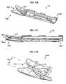
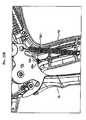
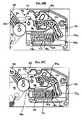
- FIG. 1Ais a side view of one exemplary embodiment of a surgical clip applier
- FIG. 1Bis an exploded view of the surgical clip applier shown in FIG. 1A ;
- FIG. 2Ais a top view of a jaw retainer assembly of the surgical clip applier shown in FIG. 1A ;
- FIG. 2Bis a bottom view of the jaw retainer assembly shown in FIG. 2A ;
- FIG. 2Cis a side view of the jaw retainer assembly shown in FIG. 2B ;
- FIG. 2Dis a cross-sectional view of the jaw retainer assembly shown in FIG. 2C taken across line D-D;
- FIG. 3Ais a top view of a feeder shoe for use with the jaw retainer assembly shown in FIGS. 2A-2D ;
- FIG. 3Bis a bottom view of the feeder shoe shown in FIG. 3A ;
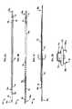
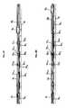
- FIG. 4Ais a side perspective view of a feed bar that is configured to advance the feeder shoe of FIGS. 3A and 3B through the jaw retainer assembly shown in FIGS. 2A-2D ;
- FIG. 4Bis a side view of the proximal end of the feed bar shown in FIG. 4A and the proximal end of the jaw retainer shaft shown in FIGS. 2A and 2B , showing the feed bar in a proximal-most position;
- FIG. 4Cis a side view of the feed bar and jaw retainer shaft shown in FIG. 4B , showing the feed bar in a distal-most position;
- FIG. 4Dis a side view of another embodiment of a proximal end of a feed bar shown in connection with the proximal end of the jaw retainer shaft shown in FIGS. 2A and 2B , showing the feed bar in the proximal-most position;
- FIG. 4Eis a side view of the feed bar and jaw retainer shaft shown in FIG. 4D , showing the feed bar in a distal-most position;
- FIG. 4Fis a side view of yet another embodiment of a proximal end of a feed bar shown in connection with the proximal end of the jaw retainer shaft shown in FIGS. 2A and 2B , showing the feed bar in the proximal-most position;
- FIG. 4Gis a side view of the feed bar and jaw retainer shaft shown in FIG. 4F , showing the feed bar in an intermediate position;
- FIG. 4His a side view of the feed bar and jaw retainer shaft shown in FIG. 4F , showing the feed bar in a distal-most position;
- FIG. 5Ais a side perspective view of an advancer that is configured to couple to a distal end of the feed bar shown in FIG. 4A ;
- FIG. 5Bis a side perspective view of another embodiment of an advancer that is configured to couple to a distal end of the feed bar shown in FIG. 4A ;
- FIG. 6Ais a cross-sectional view of a clip advancing assembly, which includes the jaw retainer assembly shown in FIGS. 2A-2D , the feeder shoe shown in FIGS. 3A-3B , and the feed bar shown in FIG. 4A , showing the feed bar in an initial, proximal position relative to the clip track of the jaw retainer assembly;
- FIG. 6Bis a cross-sectional view of the clip advancing assembly shown in FIG. 6A , showing the feed bar moved in a distal direction;
- FIG. 6Cis a cross-sectional view of the clip advancing assembly shown in FIG. 6B , showing the feed bar moved further distally, thereby moving the feeder shoe and a clip supply disposed distally of the feeder shoe in a distal direction;
- FIG. 6Dis a cross-sectional view of the clip advancing assembly shown in FIG. 6C , showing the feed bar returned to the initial, proximal position, shown in FIG. 6A , while the feeder shoe and clip supply remain in the advanced position shown in FIG. 6C ;
- FIG. 6Eis a bottom perspective view of the advancer shown in FIG. 5A disposed within the clip track of the jaw retainer assembly shown in FIGS. 2A-2D , showing the advancer in a proximal-most position;
- FIG. 6Fis a bottom perspective view of the advancer shown in FIG. 6E , showing the advancer in a distal-most position after advancing a clip into the jaws of the surgical clip applier;
- FIG. 7is a side perspective view of a pair of jaws of the surgical clip applier shown in FIG. 1A ;
- FIG. 8is a side perspective view of a cam for use with the jaws shown in FIG. 7 ;
- FIG. 9is a top perspective view of a push rod that is adapted to couple to the cam shown in FIG. 8 for moving the cam relative to the jaws shown in FIG. 7 ;
- FIG. 10Ais a top view of the cam shown in FIG. 8 coupled to the jaws shown in FIG. 7 , showing the cam in an initial position and the jaws open;
- FIG. 10Bis a top view of the cam shown in FIG. 8 coupled to the jaws shown in FIG. 7 , showing the cam advanced over the jaws and the jaws in a closed position;
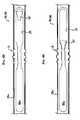
- FIG. 11Ais a top perspective view of a tissue stop that is adapted to couple to a distal end of the clip track of the jaw retainer assembly shown in FIGS. 2A-2D ;
- FIG. 11Bis a top perspective view of another embodiment of a tissue stop having a ramp formed thereon for guiding a clip into the jaws and stabilizing the clip during clip formation;
- FIG. 11Cis a side view of the tissue stop shown in FIG. 11B ;
- FIG. 11Dis an enlarged view of the tissue stop shown in FIGS. 11B and 11C ;
- FIG. 12is a top view of a distal end of the surgical clip applier shown in FIG. 1A showing the tissue stop shown in FIG. 11A positioned between the jaws shown in FIG. 7 ;
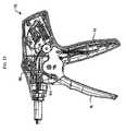
- FIG. 13is a side, partially cross-sectional view of the handle portion of the surgical clip applier shown in FIG. 1A ;
- FIG. 14is a side perspective view of a trigger insert of the surgical clip applier shown in FIG. 1A ;
- FIG. 15Ais a side perspective view of one half of a feed bar coupler of the surgical clip applier shown in FIG. 1A ;
- FIG. 15Bis a side perspective view of the other half of the feed bar coupler shown in FIG. 15A ;
- FIG. 16is a top perspective view of a flexible link that forms part of a clip advancing assembly of the surgical clip applier shown in FIG. 1A ;
- FIG. 17Ais a side, partially cross-sectional view of a portion of the handle of the surgical clip applier shown in FIG. 1A , showing a clip advancing assembly in an initial position;
- FIG. 17Bis a side, partially cross-sectional view of a portion of the handle of the surgical clip applier shown in FIG. 17A , showing the clip advancing assembly partially actuated;
- FIG. 17Cis a side, partially cross-sectional view of a portion of the handle of the surgical clip applier shown in FIG. 17B , showing the clip advancing assembly fully actuated;
- FIG. 17Dis a side, partially cross-sectional view of a portion of the handle of the surgical clip applier shown in FIG. 17A , showing a clip forming assembly actuated;
- FIG. 18is a side view of a closure link roller that forms part of a clip forming assembly of the surgical clip applier shown in FIG. 1A ;
- FIG. 19is a top perspective view of a closure link that couples to the closure link roller shown in FIG. 18 to form part of a clip forming assembly of the surgical clip applier shown in FIG. 1A ;
- FIG. 20Ais a top perspective view of a closure link coupler that couples to the closure link shown in FIG. 19 and that also forms part of the clip forming assembly of the surgical clip applier shown in FIG. 1A ;
- FIG. 20Bis a bottom view of the closure link coupler shown in FIG. 20A coupled to the push rod of FIG. 9 and having one embodiment of a biasing element disposed therein;
- FIG. 20Cis a bottom view of the closure link shown in FIG. 20A coupled to the push rod of FIG. 9 and having another embodiment of a biasing element disposed therein;
- FIG. 20Dis a chart showing the amount of force required to displace the biasing element shown in FIG. 20B ;
- FIG. 20Eis a side view of another embodiment of a portion of a closure link coupler having ridges formed therein;
- FIG. 21Ais an enlarged side perspective view of an anti-backup mechanism of the surgical clip applier shown in FIG. 1A ;
- FIG. 21Bis a perspective view of a pawl mechanism of the anti-backup mechanism shown in FIG. 21A ;
- FIG. 22Ais a side, partially cross-sectional view of a portion of the handle of the surgical clip applier shown in FIG. 1A , showing the anti-backup mechanism in an initial position;
- FIG. 22Bis a side, partially cross-sectional view of a portion of the handle of the surgical clip applier shown in FIG. 22A , showing the anti-backup mechanism in a partially actuated position;
- FIG. 22Cis a side, partially cross-sectional view of a portion of the handle of the surgical clip applier shown in FIG. 22B , showing the anti-backup mechanism in a fully actuated position;
- FIG. 22Dis a side, partially cross-sectional view of a portion of the handle of the surgical clip applier shown in FIG. 22C , showing the anti-backup mechanism returning to an initial position;
- FIG. 22Eis a side, partially cross-sectional view of a portion of the handle of the surgical clip applier shown in FIG. 22D , showing the anti-backup mechanism returned to the initial position;
- FIG. 23Ais an exploded view of an overload mechanism of the surgical clip applier shown in FIG. 1A ;
- FIG. 23Bis a partially cross-sectional view of the overload mechanism shown in FIG. 23A , showing the closure link roller first coming into contact with the profile link;
- FIG. 23Cis a partially cross-sectional view of the overload mechanism shown in FIG. 23B , showing the closure link roller applying a force to the profile link causing the profile link to pivot;
- FIG. 23Dis a perspective view of another embodiment of an overload mechanism for use with a surgical clip applier
- FIG. 24Ais a side perspective view of a clip quantity indicator wheel of the surgical clip applier shown in FIG. 1A ;
- FIG. 24Bis a side view of a clip quantity indicator wheel shown in FIG. 24A ;
- FIG. 25is a top perspective view of a clip quantity actuator for use with the clip quantity indicator wheel shown in FIG. 24 ;
- FIG. 26Ais a side, partially cross-sectional view of a portion of the handle of the surgical clip applier shown in FIG. 1A , showing movement of the clip quantity actuator of FIG. 25 and the clip quantity indicator wheel of FIG. 24 ;
- FIG. 26Bis a side, partially cross-sectional view of a portion of the handle of the surgical clip applier shown in FIG. 26A , showing further movement of the clip quantity actuator of FIG. 25 and the clip quantity indicator wheel of FIG. 24 ;
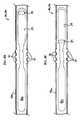
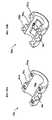
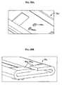
- FIG. 27Ais a side view illustration showing another embodiment of a feeder shoe having a pre-formed A-shaped bend formed therein and configured to create friction between the feeder shoe and the clip track;
- FIG. 27Bis a side view illustration of another embodiment of a feeder shoe having a pre-formed V-shaped bend formed therein and configured to create friction between the feeder shoe and the clip track;
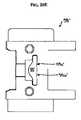
- FIG. 28Ais a perspective top view of a portion of a clip track having surface protrusions formed therein and configured to create friction between with the feeder shoe according to another embodiment of the invention.
- FIG. 28Bis perspective end view of another embodiment of a feeder shoe having a tang formed thereon and adapted to engage the surface protrusions formed in the clip track shown in FIG. 28A ;
- FIG. 29Ais a bottom perspective view of another embodiment of a feeder shoe having a holdback lip formed on a tang that is adapted to engage a corresponding groove formed in a feed bar;
- FIG. 29Bis a top perspective view of another embodiment of a feed bar having a catch groove formed therein and adapted to be engaged by the holdback lip formed on the tang of the feeder shoe shown in FIG. 29A ;
- FIG. 29Cis a side cross-sectional view of the feeder shoe of FIG. 29A disposed within and engaging the feed bar of FIG. 29B .
- the present inventiongenerally provides a surgical clip applier and methods for using a surgical clip applier to apply surgical clips to a vessel, duct, shunt, etc., during a surgical procedure.
- An exemplary surgical clip appliercan include a variety of features to facilitate application of a surgical clip, as described herein and illustrated in the drawings. However, a person skilled in the art will appreciate that the surgical clip applier can include only some of these features and/or it can include a variety of other features known in the art.
- the surgical clip applier described hereinis merely intended to represent certain exemplary embodiments.
- FIG. 1Aillustrates one exemplary surgical clip applier 10 .
- the clip applier 10generally includes a housing 12 having a stationary handle 14 and a movable handle or trigger 16 that is pivotally coupled to the housing 12 .
- An elongate shaft 18extends from the housing 12 and it includes a pair of opposed jaws 20 formed on a distal end thereof for crimping a surgical clip.
- the elongate shaft 18can be rotatably coupled to the housing 12 , and it can include a rotation knob 22 for rotating the shaft 18 relative to the housing 12 .
- FIG. 1Billustrates an exploded view of the surgical clip applier 10 shown in FIG. 1A , and the various components will be described in more detail below.
- FIGS. 2A-12illustrate exemplary embodiments of the various components of the shaft 18 of the surgical clip applier 10 .
- the shaft 18includes an outer tube 24 that houses the shaft components, which can include a jaw retaining assembly 26 having a jaw retainer shaft 28 with a clip track 30 and a push rod channel 32 formed thereon.
- the jaws 20can be configured to mate to a distal end of the clip track 30 .
- the shaft assembly 18can also include a clip advancing assembly, which in one exemplary embodiment can include a feeder shoe 34 that is adapted to be slidably disposed within the clip track 30 to advance a series of clips 36 positioned therein, and a feed bar 38 that is adapted to drive the feeder shoe 34 through the clip track 30 .
- the feed bar 38can include an advancer assembly 40 that is adapted to mate to a distal end thereof for advancing a distal-most clip into the jaws 20 .
- the shaft assembly 18can also include a clip forming or camming assembly, which in one exemplary embodiment can include a cam 42 that is adapted to slidably mate to the jaws 20 , and a push rod 44 that can couple to the cam 42 to move the cam 42 relative to the jaws 20 .
- the shaft assemblycan also include a tissue stop 46 that can mate to a distal end of the clip track 30 for facilitating positioning of the jaws 20 relative to a surgical site.
- the jaw retaining assembly 26includes an elongate, substantially planar jaw retainer shaft 28 having a proximal end 28 a that mates to the outer tube 24 , and a distal end 28 b that is adapted to mate to the jaws 20 .
- the proximal end 28 aincludes teeth 31 formed on opposed sides thereof that are adapted to be received within corresponding holes or openings (not shown) formed in the outer tube 24 , and a cut-out 29 formed therein that allows the opposed sides of the proximal end 28 a to deflect or to form a spring.
- the cut-out 29allows the opposed sides of the proximal end 28 a of the jaw retainer shaft 28 to be compressed toward one another when the jaw retainer shaft 28 is inserted in the outer tube 24 .
- the proximal end 28 a of the jaw retainer shaft 28will return to its original, uncompressed configuration thereby causing the teeth 31 to extend into the corresponding openings to engage the outer 24 .
- the devicecan also include a feature to prevent compression of the opposed sides of the proximal end 28 a of the jaw retainer shaft 28 during use of the device to prevent accidental disengagement of the teeth 31 from the outer tube 24 .
- the distal end 28 b of the jaw retainer shaft 28includes several cut-outs or teeth 78 formed therein for mating with corresponding protrusions or teeth 94 formed on the jaws 20 , which will be discussed in more detail below with respect to FIG. 7 .
- the teeth 78allow a proximal portion of the jaws 20 to be substantially co-planar with the jaw retainer shaft 28 .
- the jaw retaining assembly 26can also include a push rod channel 32 formed thereon for slidably receiving the push rod 44 , which is used to advanced the cam 42 over the jaws 20 , as will be discussed in more detail below.
- the push rod channel 32can be formed using a variety of techniques, and it can have any shape and size depending on the shape and size of the push rod 44 . As shown in FIG. 2D , the push rod channel 32 is fixedly attached, e.g., by welding, to a superior surface of the retainer shaft 28 , and it has a substantially rectangular shape and defines a pathway 32 a extending therethrough. The push rod channel 32 can also extend along all or only a portion of the retainer shaft 28 . A person skilled in the art will appreciate that the jaw retaining assembly 26 does not need to include a push rod channel 32 for facilitating movement of the push rod 44 within the elongate shaft 18 of the surgical clip applier 10 .
- the jaw retaining assembly 26can also include a clip track 30 mated thereto or formed thereon.
- the clip track 30is shown mated to an inferior surface of the jaw retainer shaft 28 , and it extends distally beyond the distal end 28 b of the jaw retainer shaft 28 to allow a distal end 30 b of the clip track 30 to be substantially aligned with the jaws 20 .
- the clip track 30is configured to seat at least one, and preferably a series, of clips therein.
- the clip track 30can include opposed side rails 80 a , 80 b that are adapted to seat opposed legs of one or more clips therein, such that the legs of the clips are axially aligned with one another.
- the clip track 30can be configured to seat about twenty clips that are pre-disposed within the clip track 30 during manufacturing.
- shape, size, and configuration of the clip track 30can vary depending on the shape, size, and configuration of clips, or other closure devices such as staples, adapted to be received therein.
- a variety of other techniquescan be used, instead of a clip track 30 , to retain a clip supply with the elongate shaft 18 .
- the clip track 30can also include several openings 30 c formed therein for receiving a tang 82 a formed on a feeder shoe 34 adapted to be disposed within the clip track 30 , as will be discussed in more detail below.
- the clip track 30includes a quantity of openings 30 c that corresponds to at least the number of clips adapted to be pre-disposed within the device 10 and applied during use.
- the openings 30 care preferably equidistant from one another to ensure that the tang 82 a on the feeder shoe 34 engages an opening 30 c each time the feeder shoe 34 is advanced.
- the clip track 30can include detents, rather than openings 30 c , or it can include other features that allow the clip track 30 to engage the feeder shoe 34 and prevent distal movement, yet allow proximal movement, of the feeder shoe 34 .
- the clip track 30can also include a stop tang 118 formed thereon, as shown in FIG. 2B , that is effective to be engaged by a corresponding stop tang formed on the feeder shoe 34 to prevent movement of the feeder shoe 34 beyond a distal-most position, as will be discussed below.
- the stop tang 118can have a variety of configurations, but in one exemplary embodiment it is in the form of two adjacent tabs that extend toward one another to enclose a portion of the clip track, thus allowing clips to pass therethrough.
- An exemplary feeder shoe 34is shown in more detail in FIGS. 3A and 3B , and it can be adapted to directly driving clips through the clip track 30 . While the feeder shoe 34 can have a variety of configurations, and a variety of other techniques can be used to drive clips through the clip track 30 , in an exemplary embodiment the feeder shoe 34 has a generally elongate shape with proximal and distal ends 34 a , 34 b . The distal end 34 b can be adapted to cradle the proximal-most clip in the clip track 30 to push the clip(s) through the clip track 30 . In the illustrated exemplary embodiment, the distal end 34 b is substantially v-shaped for seating a v-shaped bight portion of a clip.
- the distal end 34 balso includes a rectangular-shaped notch 34 c formed therein for allowing the advancer 40 to engage a distal-most clip and advance it into the jaws 20 , as will be discussed in more detail below.
- the distal end 34 bcan, of course, vary depending on the configuration of the clip, or other closure mechanism, being used with the device 10 .
- the feeder shoe 34can also include features to facilitate distal movement of the feeder shoe 34 within the clip track 30 , and to substantially prevent proximal movement of the feeder shoe 34 within the clip track 30 . Such a configuration will ensure advancement and proper positioning of the clips within the clip track 30 , thus allowing a distal-most clip to be advanced between the jaws 20 with each actuation of the trigger 16 , as will be discussed in more detail below.
- the feeder shoe 34includes a tang 82 a formed on a superior surface 34 s thereof and angled proximally for engaging one of the openings 30 c formed in the clip track 30 .
- the angle of the tang 82 aallows the feeder shoe 34 to slide distally within the clip track 30 .
- the tang 82 awill move in a distal direction from one opening 30 c to the next opening 30 c in the clip track 30 .
- the engagement of the tang 82 a with the opening 30 c in the clip track 30will prevent the feeder shoe 34 from moving proximally to return to the previous position, as will be described in more detail below.
- the feeder shoe 34can also include a tang 82 b formed on the inferior surface 34 i thereof, as shown in FIG. 3B , for allowing the feeder shoe 34 to be engaged by the feed bar 38 ( FIG. 4A ) as the feed bar 38 is moved distally.
- the inferior tang 82 bis similar to the superior tang 82 a in that it can be angled proximally.
- a detent 84 formed in the feed bar 38can engage the inferior tang 82 b and move the feeder shoe 34 distally a predetermined distance within the clip track 30 .
- the feed bar 38can then be moved proximally to return to its initial position, and the angle of the inferior tang 82 b will allow the tang 82 b to slide into the next detent 84 formed in the feed bar 38 .
- tangs 82 a , 82 b and openings 30 c or detents 84can be used to control movement of the feeder shoe 34 within the clip track 30 .
- the feeder shoe 34can also include a stop formed thereon that is adapted to stop movement of the feeder shoe 34 when the feeder shoe 34 is in the distal-most position and there are no clips remaining in the device 10 .
- the stopcan have a variety of configurations
- FIGS. 3A and 3Billustrate a third tang 82 c formed on the feeder shoe 34 and extending in an inferior direction for engaging the stop tang 118 ( FIG. 2B ) formed on the clip track 30 .
- the third tang 82 cis positioned such that it will engage the stop tang 118 on the clip track 30 when the feeder shoe 34 is in a distal-most position, thereby preventing movement of the feeder shoe 34 and the feed bar 38 when the clip supply is depleted.
- FIG. 4Aillustrates an exemplary feed bar 38 for driving the feeder shoe 34 through the clip track 30 of the jaw retaining assembly 26 .
- the feed bar 38has a generally elongate shape with proximal and distal ends 38 a , 38 b .
- the proximal end 38 a of the feed bar 38 acan be adapted to mate to a feed bar coupler 50 ( FIG. 1B ), which will be discussed in more detail below.
- the feed bar coupler 50can mate to a feed link 52 that is effective, upon actuation of the trigger 16 , to slidably move the feed bar 38 in a distal direction within the elongate shaft 18 .
- the distal end 38 b of the feed bar 38 bcan be adapted to mate to an advancer 40 , 40 ′, exemplary embodiments of which are shown in FIGS. 5A and 5B , that is effective to drive a distal-most clip disposed within the clip track 30 into the jaws 20 , which will be discussed in more detail below.
- the proximal end 38 a of the feed bar 38can include a feature to prevent compression of the opposed sides of the proximal end 28 a of the jaw retainer shaft 28 ( FIGS. 2A and 2B ) during use of the device to prevent accidental disengagement of the teeth 31 from the outer tube 24 .
- the proximal end 38 a of the feed bar 38can include a protrusion 39 formed thereon that is adapted to extend into the opening 29 formed in the proximal end 28 a of the jaw retainer shaft 28 .
- the protrusion 39When the feed bar 38 is in a proximal-most position (i.e., when the trigger 16 is in an open position), the protrusion 39 will be positioned at the proximal end of the opening 29 , as shown in FIG. 4B , allowing the proximal end 28 a of the jaw retainer shaft 28 to compress to allow the shaft 28 to slide into the outer tube 24 .
- the protrusion 39When the feed bar 38 is in a distal-most position (i.e., when the trigger 16 is in at least a partially closed position), the protrusion 39 will be positioned at an intermediate location adjacent to the teeth 31 as shown in FIG. 4C , to prevent compression of the proximal end 28 a of the jaw retainer shaft 28 .
- FIGS. 4A-4Cillustrate a protrusion 39 having a rectangular cross-sectional shape with rounded edges
- the protrusion 39can have a variety of other shapes and sizes.
- the protrusion 39 ′has a cross-sectional shape that is somewhat triangular with a tapering end that is adapted to extend between the teeth 31 to further ensure that the proximal end 28 a of the jaw retainer shaft 28 can not be compressed during use of the device.
- More than one protrusioncan also be used. For example, FIGS.
- FIG. 4F-4Hillustrate another embodiment in which the proximal end 38 a ′ of the feed bar 38 includes two protrusions 39 a , 39 b formed thereon and spaced a distance apart from one another.
- the two protrusions 39 a , 39 bwill prevent compression of the proximal end 28 a of the jaw retainer shaft 28 when the feed bar 38 is in a proximal-most position, as shown in FIG. 4F , and when the feed bar 38 is in a distal-most position, as shown in FIG. 4H .
- Compression of the proximal end 28 a of the jaw retainer shaft 28can only occur when the feed bar 38 is at an intermediate position such that the teeth 31 are positioned between the protrusions 39 a , 39 b , as shown in FIG. 4G .
- the feed bar 38can include one or more detents 84 formed therein for engaging the inferior tang 82 b formed on the feeder shoe 34 .
- the quantity of detents 84can vary, but in an exemplary embodiment the feed bar 38 has a quantity of detents 84 that corresponds to or is greater than a quantity of clips adapted to be delivered by the device 10 , and more preferably it has one more detent 84 than the quantity of clips adapted to be delivered by the device 10 .
- the feed bar 38can include eighteen detents 84 formed therein for delivering seventeen clips that are pre-disposed within the clip track 30 .
- Such a configurationallows the feed bar 38 to advance the feeder shoe 34 seventeen times, thereby advancing seventeen clips into the jaws 20 for application.
- the detents 84are also preferably equidistant from one another to ensure that the feeder shoe 34 is engaged and advanced by the feed bar 38 each time the feed bar 38 is advanced.
- the feed bar 38can also include a feature to control the amount of movement of the feed bar 38 relative to the clip track 30 . Such a configuration will ensure that the feeder shoe 34 is advanced a predetermined distance each time the trigger 16 is actuated, thereby advancing only a single clip into the jaws 20 . While a variety of techniques can be used to control the distal of movement of the feed bar 38 , in an exemplary embodiment the feed bar 38 can include a protrusion 86 formed thereon that is adapted to be slidably received within a corresponding slot 88 ( FIG. 2B ) formed in the jaw retainer shaft 28 . The length of the slot 88 is effective to limit movement of the protrusion 86 therein, thus limiting movement of the feed bar 38 .
- the feed bar 38can slide between a fixed proximal position and a fixed distal position with respect to the clip track 30 , thereby allowing the feed bar 38 to advance the feeder shoe 34 by a predetermined distance with each advancement of the feed bar 38 .
- FIG. 5Aillustrates one exemplary embodiment of an advancer 40 that is adapted to mate to the distal end 38 b of the feed bar 38 and which is effective to drive a distal-most clip from the clip track 30 into the jaws 20 .
- a variety of techniquescan be used to mate the advancer 40 to the feed bar 38 , but in the illustrated embodiment the proximal end 40 a of the advancer 40 is in the form of a female connector that is adapted to receive the male connector formed on the distal end 38 b of the feed bar 38 .
- the advancer 40preferably fixedly mates to the feed bar 38 , however it can optionally be integrally formed with the feed bar 38 .
- the distal end 40 b of the feed bar 38is preferably adapted to advance a clip into the jaws 20 and thus the distal end 40 b of the advancer 40 can include, for example, a clip-pusher member 90 formed thereon.
- the clip-pusher member 90can have a variety of shapes and sizes, but in one exemplary embodiment it has an elongate shape with a recess 92 formed in the distal end thereof for seating the bight portion of a clip.
- the shape of the recess 92can vary depending on the particular configuration of the clip.
- the clip-pusher member 90can also extend at an angle in a superior direction with respect to a longitudinal axis A of the advancer 40 .
- FIG. 5Billustrates another exemplary embodiment of a clip-pusher member 90 ′ of an advancer 40 ′.
- the clip-pusher member 90 ′is slightly more narrow and it has a small recess 92 ′ formed in the distal-most end thereof.
- the advancer 40can engage and advance only the distal-most clip disposed within the clip track 30 into the jaws 20 . This is due to the positioning of the feed bar 38 , which is slidably movable between a fixed proximal and distal positions, as previously discussed.
- FIGS. 6A-6Gillustrate the clip advancing assembly in use, and in particular FIGS. 6A-6D illustrate movement of the feed bar 38 within the clip track 30 to advance the feeder shoe 34 and clip supply 36 , and FIGS. 6E-6F illustrate movement of the advancer 40 to advance a distal-most clip into the jaws 20 .
- the components in the housing 12 that are used to actuate the clip advancing assemblywill be discussed in more detail below.
- the feed bar 38in the resting position the feed bar 38 is in a proximal-most position such that the protrusion 86 is positioned proximally within the elongate slot 88 in the jaw retainer shaft 28 .
- the feeder shoe 34is disposed within the clip track 30 and, assuming the device 10 has not yet been used, the feeder shoe 34 is in a proximal-most position such that the superior tang 82 a on the feeder shoe 34 is engaged with the proximal-most or first opening 30 c 1 formed in the clip track 30 to prevent proximal movement of the feeder shoe 34 , and the inferior tang 82 b on the feeder shoe 34 is positioned between the first detent 84 1 and the second detent 84 2 in the feed bar 38 , such that the inferior tang 82 b is biased in a superior direction by the feed bar 38 .
- the detents 84 in the feed barare labeled sequentially as 84 1 , 84 2 , etc.
- the openings 30 c in the clip track 30are labeled sequentially as 30 c 1 , 30 c 2 , etc.
- a series of clips 36labeled sequentially as 36 1 , 36 2 , . . . 36 x with 36 x being the distal-most clip, are positioned within the clip track 30 distal of the feeder shoe 34 .
- the feed bar 38Upon actuation of the trigger 16 , the feed bar 38 is advanced distally, causing the protrusion 86 to slide distally within the slot 88 . As the feed bar 38 moves distally, the inferior tang 82 b on the feeder shoe 34 will slide into the first detent 84 1 in the feed bar 38 . Further distal movement of the feed bar 38 will cause the first detent 84 1 to engage the inferior tang 82 b , as shown in FIG. 6B , and to move the feeder shoe 34 and clip supply 36 1 , 36 2 , etc. in a distal direction. As shown in FIG.
- the feeder shoe 34has advanced a predetermined distance to advance the clip supply 36 1 , 36 2 , . . . 36 x within the clip track 30 by a predetermined distance.
- the superior tang 82 a of the feeder shoe 34has been advanced into the second opening 30 c 2 in the clip track 30 to prevent proximal movement of the feeder shoe 34 , and the inferior tang 82 b on the feeder shoe 34 is still engaged by the first detent 84 1 in the feed bar 38 .
- Movement of the feed bar 38 from the initial, proximal-most position, shown in FIG. 6A , to the final, distal-most position, shown in FIG. 6C ,will also advance the distal-most clip 36 x into the jaws 20 .
- distal movement of the feed bar 38will cause the clip-pusher member 90 of the advancer 40 , which is attached to the distal end of the feed bar 38 , to engage the distal-most clip 36 x disposed within the clip track 30 and to advance the clip 36 x into the jaws 20 , as shown in FIG. 6F .
- the advancer 40will engage and initiate advancement of the distal-most clip 36 x prior to engaging and initiating advancement of the feeder shoe 34 .
- the distal-most clip 36 xwill advance a distance that is greater than a distance traveled by the feeder shoe 34 .
- Such a configurationallows only the distal-most clip 36 x to be advanced into the jaws 20 without accidentally advancing an additional clip into the jaws 20 .
- the trigger 16can be released to release the formed clip 36 x . Release of the trigger 16 will also retract the feed bar 38 in a proximal direction until the protrusion 86 returns to the initial proximal-most position within the elongate slot 88 , as shown in FIG. 6D . As the feed bar 38 is retracted proximally, the feeder shoe 34 will not move proximally since the superior tang 82 a will engage the second opening 30 c 2 in the clip track 30 .
- the inferior tang 82 bwill not interfere with proximal movement of the feed bar 38 , and once the feed bar 38 is in the initial, proximal-most position, as shown, the inferior tang 82 b will be positioned between the second detent 84 2 and the third detent 84 3 in the feed bar 38 .
- the processcan be repeated to advance another clip into the jaws 20 .
- the inferior tang 82 bwill be engaged by the next detent, i.e., detent 84 2 formed in the feed bar 38
- the superior tang 82 a on the feeder shoe 34will be moved distally into the next opening, i.e., opening 30 c 3 on the clip track 30
- the distal-most clipwill be advanced into the jaws 20 and released.
- the device 10includes a predetermined amount of clips, e.g., seventeen clips
- the trigger 16can be actuated seventeen times.
- the stope.g., the third tang 82 c
- the feeder shoe 34can engage the stop tang 118 on the clip track 30 to prevent further distal movement of the feeder shoe 34 .
- the feeder shoe 34 , feed bar 38 , and/or the clip track 30can also optionally include features to prevent accidental or unintentional movement of the feeder shoe 34 , for example during shipment of the device. This is particularly advantageous as migration of the feeder shoe 34 , particularly prior to first use of the device, can cause the device to malfunction. For example, if the feeder shoe 34 migrates distally, the feeder shoe 34 will advance two clips into the jaws simultaneously, thereby resulting in delivery of two misformed clips.
- the feeder shoe 34 , feed bar 38 , and/or the clip track 30can include an engagement mechanism and/or can be configured to generate a frictional force therebetween that is sufficient to resist movement, but that can be overcome by actuation of the trigger 16 to allow the feed bar to advance the feeder shoe 34 through the clip track 30 .
- FIGS. 27A-29Cillustrate various exemplary embodiments of techniques for creating friction or an engagement mechanism between the feeder shoe 34 , feed bar 38 , and/or the clip track 30 .
- FIG. 27Aone exemplary embodiment of a feeder shoe 34 ′ is shown having a pre-formed cantilevered or bowed configuration in a free state (i.e., when the feeder shoe 34 ′ is removed from the clip track 30 ) such that the feeder shoe 34 ′ forms a cantilevered spring when disposed within the clip track 30 .
- a portion of the feeder shoe 34 ′can include a bend 35 ′ formed therein such that the opposed ends 34 a ′, 34 b ′ of the feeder shoe 34 ′ are angled relative to one another.
- the bend 35 ′can cause the height h b of the feeder shoe 34 ′ to be greater than the height of the clip track 30 .
- the bend 35 ′is configured to increase a height of the feeder shoe 34 ′ by an amount that is sufficient to create a frictional drag force between the feeder shoe 34 ′ and the clip track 30 , but that still allows the feeder shoe 34 ′ to slide within the clip track 30 when the trigger 16 is actuated.
- the height of the feeder shoe 34 ′is increased at least about 30%, or more preferably about 40%.
- the clip track 30will force the feeder shoe 34 ′ into a substantially planar configuration such that the feeder shoe 34 ′ is biased against the clip track 30 when disposed therein.
- the bend 35 ′ of the feeder shoe 34 ′, as well as the terminal ends 34 a ′, 34 b ′ of the feeder shoe 34 ′,will therefore apply a force to the clip track 30 , thereby creating a frictional drag force between the feeder shoe 34 ′ and the clip track 30 .
- the frictional forcewill prevent the feeder shoe 34 ′ from migrating relative to the clip track 30 unless the trigger 16 is actuated, in which case the force applied by the trigger 16 will overcome the frictional forces.
- the bend 35 ′can have a variety of configurations, and it can be formed anywhere along the length of the feeder shoe 34 ′.
- the bend 35 ′is formed at or near the mid-portion of the feeder shoe 34 ′.
- the bend 35 ′can also extend in various directions. While FIG. 27A illustrates the bend 35 ′ extending in a direction perpendicular to the axis such that the bend 35 ′ and the ends 34 a ′, 34 b ′ apply a force to the clip track 30 , the bend 35 ′ can alternatively extend along a longitudinal axis of the feeder shoe 34 ′ such that the feeder shoe 34 ′ applies a force to the opposed side rails 80 a , 80 b ( FIG.
- the bend 35 ′can also angle the opposed ends 34 a ′, 34 b ′ in a downward direction, as shown in FIG. 27A , such that the feeder shoe 34 ′ is substantially A-shaped, or alternatively the bend 35 ′′ can angle the opposed ends 34 a ′′, 34 b ′′ in an upward direction, as shown in FIG. 27B , such that the feeder shoe 34 ′′ is substantially V-shaped.
- the feeder shoe 34 ′can also include any number of bends formed therein. A person skilled in the art will appreciate that the particular configuration of the bend(s) can be modified based on the properties of the feeder shoe 34 ′ and the clip track 30 to obtain a desired amount of frictional force therebetween.
- FIGS. 28A and 28Billustrate another embodiment of a technique for creating frictional forces between the feeder shoe and clip track.
- the clip track 30 ′ and/or the feeder shoe 34 xcan include one or more surface protrusions formed thereon. As shown in FIG. 28A , two surface protrusions 82 d 1 , 82 d 2 are formed on the clip track 30 ′.
- the surface protrusions 82 d 1 , 82 d 2can be formed at various locations on the clip track 30 ′, including inside the opposed side rails or along the entire length of the clip track 30 ′, or at various locations on the feeder shoe 34 x
- two protrusions 82 d 1 , 82 d 2are formed adjacent to the proximal end of the clip track 30 ′ and they are positioned to prevent initial migration of the feeder shoe prior to use, e.g., during shipping.
- the size of the protrusions 82 d 1 , 82 d 2can vary depending upon the amount of frictional force necessary to prevent unintentional migration of the feeder shoe 34 x .
- the feeder shoe 34 x and/or clip track 30 ′can optionally include a feature that is adapted to engage corresponding surface protrusions.
- FIG. 28Billustrates opposed tangs 82 e 1 , 82 e 2 formed on a distal portion of the feeder shoe 34 x for engaging the protrusions 82 d 1 , 82 d 2 on the clip track 30 ′.
- the tangs 82 e 1 , 82 e 2can vary in shape and size, and they can include a lip or other protrusion configured to engage or “catch” the protrusions 82 d 1 , 82 d 2 . As shown in FIG. 28B , the tangs 82 e 1 , 82 e 2 extend toward one another from opposed sidewalls of the feeder show 34 x .
- FIGS. 29A-29Cillustrate another embodiment of a technique for preventing unintentional migration of the feeder shoe.
- frictionis generated between the feeder shoe and the feed bar.
- the feeder shoe 34 yincludes a tang 82 f with a lip 82 g formed thereon, as shown in FIG. 29A
- the feed bar 38 yincludes a corresponding groove 84 y formed therein.
- the lip 82 gis configured to engage the groove 84 y to prevent unintentional migration of the feeder shoe 34 y .
- the lip 82 g and groove 84 yare configured to allow movement of the feeder shoe 34 y when a sufficient force is applied to the feeder shoe 34 y by actuation of the trigger 16 .
- FIGS. 7-9illustrate various exemplary components of a clip forming assembly.
- the jaws 20can include a proximal portion 20 a having teeth 94 for mating with corresponding teeth 78 formed on the jaw retaining shaft 28 .
- Other techniquescan, however, be used to mate the jaws 20 to the jaw retaining shaft 28 .
- a dovetail connection, a male-female connection, etc.can be used.
- the jaws 20can be integrally formed with the retaining shaft 28 .
- the distal portion 20 b of the jaws 20can be adapted to receive a clip therebetween, and thus the distal portion 20 b can include first and second opposed jaw members 96 a , 96 b that are movable relative to one another.
- the jaw members 96 a , 96 bare biased to an open position, and a force is required to move the jaw members 96 a , 96 b toward one another.
- the jaw members 96 a , 96 bcan each include a groove (only one groove 97 is shown) formed therein on opposed inner surfaces thereof for receiving the legs of a clip in alignment with the jaw members 96 a , 96 b .
- the jaws members 96 a , 96 bcan also each include a cam track 98 a , 98 b formed therein for allowing the cam 42 to engage the jaw members 96 a , 96 b and move the jaw members 96 a , 96 b toward one another.
- the cam track 98 a , 98 bis formed on a superior surface of the jaw members 96 a , 96 b.
- FIG. 8illustrates an exemplary cam 42 for slidably mating to and engaging the jaw members 96 , 96 b .
- the cam 42can have a variety of configurations, but in the illustrated embodiment it includes a proximal end 42 a that is adapted to mate to a push rod 44 , discussed in more detail below, and a distal end 42 b that is adapted to engage the jaw members 96 a , 96 b .
- a variety of techniquescan be used to mate the cam 42 to the push rod 44 , but in the illustrated exemplary embodiment the cam 42 includes a female or keyed cut-out 100 formed therein and adapted to receive a male or key member 102 formed on the distal end 44 b of the push rod 44 .
- the male member 102is shown in more detail in FIG. 9 , which illustrates the push rod 44 .
- the male member 102has a shape that corresponds to the shape of the cut-out 100 to allow the two members 42 , 44 to mate.
- the cam 42 and the push rod 44can optionally be integrally formed with one another.
- the proximal end 44 a of the push rod 44can be adapted to mate to a closure link assembly, discussed in more detail below, for moving the push rod 44 and the cam 42 relative to the jaws 20 .
- the cam 42can also include a protrusion 42 c formed thereon that is adapted to be slidably received within an elongate slot 20 c formed in the jaws 20 .
- the protrusion 42 c and the slot 20 ccan function to form a proximal stop for the clip forming assembly.
- the distal end 42 b of the cam 42can be adapted to engage the jaw members 96 a , 96 b . While a variety of techniques can be used, in the illustrated exemplary embodiment the distal end 42 b includes a camming channel or tapering recess 104 formed therein for slidably receiving the cam tracks 98 a , 98 b on the jaw members 96 a , 96 b . In use, as shown in FIGS.
- the cam 42can be advanced from a proximal position, in which the jaw members 96 a , 96 b are spaced a distance apart from one another, to a distal position, in which the jaw members 96 a , 96 b are positioned adjacent to one another and in a closed position.
- the tapering recess 104will push the jaw members 96 a , 96 b toward one another, thereby crimping a clip disposed therebetween.
- the surgical clip applier 10can also include a tissue stop 46 for facilitating positioning of the tissue at the surgical site within jaws 20 .
- FIG. 11Ashows one exemplary embodiment of a tissue stop 46 having proximal end and distal ends 46 a , 46 b .
- the proximal end 46 acan be adapted to mate to a distal end of the clip track 30 for positioning the tissue stop 46 adjacent to the jaws 20 .
- the tissue stop 46can be integrally formed with the clip track 30 , or it can be adapted to mate to or be integrally formed with a variety of other components of the shaft 18 .
- the distal end 46 b of the tissue stop 46can have a shape that is adapted to seat a vessel, duct, shunt, etc. therebetween to position and aligned the jaws 20 relative to the target site. As shown in FIG. 11A the distal end 46 b of the tissue stop 46 is substantially v-shaped. The distal end 46 b can also have a curved configuration to facilitate placement of the device through a trocar or other access tube.
- the tissue stop, or other components of the devicecan also optionally include features to support and stabilize a clip during clip formation.
- the clipWhen a clip is being formed between the jaws, the clip can pivot and become misaligned.
- the terminal end of each leg of the clipwill be moved toward one another.
- the jawswill only engage a bend portion on each leg, thus allowing the terminal ends of the legs and the apex of the clip to swing out of alignment with the jaws, i.e., to pivot vertically relative to the jaws. Further closure of the jaws can thus result in a malformed clip.
- the devicecan include features to align and guide the clip into the jaws, and to prevent the clip from pivoting or otherwise becoming misaligned during clip formation.
- FIG. 11Aillustrates a central tang 47 formed at a mid-portion of the distal end 46 b of the tissue stop 46 for maintaining a clip in alignment with the tip of the advancer assembly 40 .
- the central tang 47can allow the apex of a clip to ride therealong thus preventing the clip from becoming misaligned relative to the advancer assembly 40 that is pushing the clip in a distal direction.
- the tissue stop 46can have a variety of other configurations, and it can include a variety of other features to facilitate advancement of a clip therealong.
- FIGS. 11B-11Dillustrate another exemplary embodiment of a tissue stop 46 ′ having an alignment feature or guide member formed thereon and adapted to align and guide the clip into the jaws, and more preferably to maintain the clip in alignment with the jaws during clip formation.
- the alignment featureis in the form of a ramped member 47 ′ extending longitudinally along a central axis of the tissue stop 46 ′ and protruding above a superior surface of the tissue stop 46 ′.
- the ramped member 47 ′is preferably rigid, and increases in height from a proximal end 46 a ′ to a distal end 46 b ′ of the tissue stop 46 ′.
- the anglecan vary, however, depending on the particular angle of the jaws.
- the ramp member 47 ′preferably terminates just proximal to the tissue-receiving recess 46 c ′ formed in the distal tip of the tissue stop 46 ′. As a result, the ramped member 47 ′ is positioned just proximal to the jaws 20 , thus allowing the ramped member 47 ′ to guide a clip, as well as the tip of the advancer assembly 40 that is pushing the clip, into the jaws 20 at an appropriate angle. In use, the ramped member 47 ′ can abut against an inferior surface of the apex of a clip disposed between the jaws 20 to prevent the clip from pivoting vertically as the jaws 20 are closed to form the clip.
- the ramped member 47 ′will prevent the apex from moving vertically in a downward or inferior direction, thereby preventing the legs of the clip from moving vertically in an upward or superior direction, i.e., the ramped member 47 ′ will prevent the clip from swinging within the jaws 20 .
- the ramped member 47 ′is effective to prevent or limit harmful rotational forces generated when the jaws 20 are closed to form the clip. The clip is thus maintained in alignment with the jaws 20 .
- the shape, size, and configuration of the ramp membercan vary depending on the particular configuration of the jaws and other components of the clip applier.
- the ramped member 47 ′can have a maximum height h Rmax of about 0.025′′, as measured from a central plane extending through the tissue stop 46 ′. More preferably the height h Rmax is in the range of about 0.008′′′′ to 0.020′′, and most preferably the height h Rmax is in the range of about 0.010′′ to 0.015′′.
- the incline angle ⁇ R of the ramped member 47 ′can also vary, but in an exemplary embodiment the ramped member 47 ′ has an incline angle ⁇ R in the range of about 5° to 45°, and more preferably 5° to 30°, and most preferably 10° to 20°.
- the width w r of the ramped member 47 ′can also vary, but in an exemplary embodiment the ramped member 47 ′ preferably has a width w r that is slightly less than a space between the jaws 20 in the fully closed position.
- FIG. 12illustrates the tissue stop 46 in use.
- the tissue stop 46is positioned just inferior to the jaws 20 and at a location that allows a vessel, duct, shunt etc. to be received between the jaws 20 .
- a surgical clip 36is positioned between the jaws 20 such that the bight portion 36 a of the clip 36 is aligned with the tissue stop 46 . This will allow the legs 36 b of the clip 36 to be fully positioned around the vessel, duct, shunt, or other target site.
- FIGS. 13-26Billustrate various exemplary internal components of the housing 12 for controlling clip advancement and forming.
- the surgical clip applier 10can include some or all of the features disclosed herein, and it can include a variety of other features known in the art.
- the internal components of the clip applier 10can include a clip advancing assembly, that couples to the clip advancing assembly of the shaft 18 , for advancing at least one clip through the elongate shaft 18 to position the clip between the jaws 20 , and a clip forming assembly, that couples to the clip forming assembly of the shaft 18 , for closing the jaws 20 to form a partially or fully closed clip.
- exemplary featuresinclude an anti-backup mechanism for controlling movement of the trigger 16 , an overload mechanism for preventing overload of the force applied to the jaws 20 by the clip forming assembly, and a clip quantity indicator for indicating a quantity of clips remaining in the device 10 .
- FIGS. 13-16Dillustrate an exemplary embodiment of a clip advancing assembly of the housing 12 for effecting movement of the feed bar 38 within the shaft 18 .
- the clip advancing assemblycan include a trigger insert 48 that is coupled to the trigger 16 , a feed bar coupler 50 that can mate to a proximal end 38 a of the feed bar 38 , and a feed link 52 that is adapted to extend between the trigger insert 48 and the feed bar coupler 50 for transferring motion from the trigger insert 48 to the feed bar coupler 50 .
- FIG. 14illustrates the trigger insert 48 in more detail.
- the shape of the trigger insert 48can vary depending on the other components of the housing 12 , but in the illustrated embodiment the trigger insert 48 includes a central portion 48 a that is adapted to pivotally mate to the housing 12 , and an elongate portion 48 b that is adapted to extend into and mate to the trigger 16 .
- the central portion 48 acan include a bore 106 extending therethrough for receiving a shaft for pivotally mating the trigger insert 48 to the housing 12 .
- the central portion 48 acan also include a first recess 108 formed in a superior side edge for receiving a portion of the feed link 52 .
- the first recess 108preferably has a size and shape that allows a portion of the feed link 52 to extend therein such that the feed link 52 will be forced to pivot when the trigger insert 48 pivots due to movement of the trigger 16 .
- the first recess 108is substantially elongate and includes a substantially circular portion formed therein for seating a shaft formed on a proximal end of the feed link 52 , as will be discussed in more detail with respect to FIG. 16 .
- the trigger insert 48can also include a second recess 110 formed in a back side edge for receiving a closure link roller 54 that is coupled to the push bar 44 for moving the cam 42 to close the jaws 20 , and ratchet teeth 112 formed on the bottom side edge thereof for mating with a pawl 60 for controlling movement of the trigger 16 , as will be discussed in more detail below.
- the exemplary feed bar coupler 50is shown in more detail in FIGS. 15A and 15B , and it can be adapted to couple the proximal end of the feed bar 38 to the distal end of the feed link 52 . While a variety of techniques can be used to mate the feed bar coupler 50 to the proximal end 38 a of the feed bar 38 , in an exemplary embodiment the feed bar coupler 50 is formed from two separate halves 50 a , 50 b that mate together to maintain the proximal end 38 a of the feed bar 38 therebetween.
- the two halves 50 a , 50 btogether define a central shaft 50 c having substantially circular flanges 50 d , 50 e formed on opposed ends thereof and defining a recess 50 f therebetween for seating a distal portion of the feed link 52 .
- the central shaft 50 cdefines a lumen 50 g therethrough for receiving the proximal end 38 a of the feed bar 38 and for locking the feed bar 38 in a substantially fixed position relative to the feed bar coupler 50 .
- the feed bar coupler 50can, however, be integrally formed with the feed bar 38 , and it can have a variety of other shapes and sizes to facilitate mating with the feed link 52 .
- FIG. 16illustrates an exemplary feed link 52 , which can extend between the trigger insert 48 and the feed bar coupler 52 .
- the feed link 52can have a substantially planar elongate shape with proximal and distal ends 52 a , 52 b .
- the proximal end 52 ais adapted to rotatably sit within the first recess 108 of the trigger insert 48 and thus, as previously discussed, it can include a shaft 53 ( FIG. 1B ) extending therethrough.
- the shaft 53can be adapted to pivotally rotate within the first recess 108 of the trigger insert 48 , thereby allowing the trigger insert 48 to pivot the feed link 52 .
- the distal end 52 b of the feed link 52can be adapted to couple to feed bar coupler 50 and thus, in an exemplary embodiment, it includes opposed arms 114 a , 114 b formed thereon and defining an opening 116 therebetween for seating the central shaft 50 a of the feed bar coupler 50 .
- the arms 114 a , 114 bare effective to engage and move the coupler 50 as the feed link 52 pivots about a pivot axis X.
- the pivot axis Xcan be defined by the location at which the feed link 52 couples to the housing 12 , and it can be positioned anywhere on the feed link 52 , but in the illustrated embodiment it is positioned adjacent to the proximal end 52 a of the feed link 52 .
- the feed link 52can be flexible to eliminate the need to calibrate the clip advancing assembly and the clip forming assembly.
- the feed link 52allows the trigger 16 to continue moving toward a closed position even after the feed bar 38 and feed bar coupler 50 are in a distal-most position, and it provides some freedom to the clip forming and clip advancing assemblies.
- the trigger 16is pliant relative to the feed bar 38 during closure of the trigger.
- the particular stiffness and strength of the feed link 52can vary depending on the configuration of the clip advancing assembly and the clip forming assembly, but in one exemplary embodiment the feed link 52 has a stiffness that is in the range of 75 to 110 lbs per inch, and more preferably that is about 93 lbs per inch (as measured at the interface between the link 52 and the feed bar coupler 50 ), and it has a strength of that is in the range of 25 lbs and 50 lbs, and more preferably that is about 35 lbs.
- the feed link 52can also be formed from a variety of materials, including a variety of polymers, metals, etc.
- One exemplary materialis a glass-reinforced polyetherimide, but a number of reinforced thermoplastics could be used, including glass reinforced liquid-crystal polymers, glass-reinforced nylons, and carbon-fiber reinforced versions of these and similar thermoplastics. Fiber-reinforced thermoset polymers such as thermoset polyesters could also be used. Feed link 52 could also be fabricated from a metal, such as spring steel to achieve the desired combination of limited flexibility and controlled strength.
- FIGS. 17A-17Dillustrate the exemplary clip advancing assembly in use.
- FIG. 17Ashows an initial position, wherein the trigger 16 is resting in an open position, the feed bar coupler 50 and feed bar 38 are in a proximal-most position, and the feed link 52 extends between the trigger insert 48 and the feed bar coupler 50 .
- the protrusion 86 on the feed bar 38in positioned in the proximal end of the elongate slot 88 in the jaw retainer shaft 28 .
- a first biasing membere.g., spring 120
- a second biasing membere.g., spring 122
- a shaft coupler 124which rotatably mates the shaft 18 to the housing 12
- the feed bar coupler 50to maintain the feed bar coupler 50 and feed bar 38 in the proximal-most position.
- the trigger insert 48begins to pivot in a counter-clockwise direction, as shown in FIG. 17B .
- the feed link 52is forced to pivot in a counter-clockwise direction, thereby moving the feed bar coupler 50 and feed bar 38 in a distal direction.
- the protrusion 86 on the feed bar 38thus moves distally within the elongate slot 88 in the jaw retainer shaft 28 , thereby advancing the feeder shoe 34 and the clips 36 disposed within the clip track.
- Spring 120is extended between the housing and the trigger insert 48 , and spring 122 is compressed between the feed bar coupler 50 and the shaft coupler 124 .
- the feed bar coupler 50 and feed bar 38will eventually reach a distal-most position. In this position, the protrusion 86 on the feed bar 38 will be positioned at the distal end of the slot 88 in the jaw retainer shaft 28 and a clip will be positioned between the jaws 20 , as previously discussed.
- Spring 122will be fully compressed between the shaft coupler 124 and the feed bar coupler 50 , and the feed link 52 will flex, as shown in FIGS. 17C and 17D .
- the clip forming assemblywill be actuated to close the jaws 20 .
- the feed link 52will remain flexed during actuation of the clip forming assembly, e.g., the second stage of actuation, such that the trigger insert 48 is pliant relative to the clip advancing assembly, and in particular the feed bar 38 .
- FIGS. 18-20An exemplary clip forming assembly of the housing 12 is shown in more detail in FIGS. 18-20 .
- the clip forming assemblyis disposed within the housing 12 and it is effective to move the push rod 44 and cam 42 relative to the jaws 20 to move the jaws 20 to a closed position and thereby crimp a clip positioned therebetween.
- the clip forming assemblycan have a variety of configurations
- the illustrated exemplary clip forming assemblyincludes a closure link roller 54 that is slidably coupled to the trigger insert 48 , a closure link 56 that is adapted to couple to the closure link roller 54 , and a closure coupler 58 that is adapted to couple to the closure link 56 and to the push rod 44 .
- FIG. 18illustrates the closure link roller 54 in more detail and, as shown, the closure link roller 54 includes a central shaft 54 a having substantially circular flanges 54 b , 54 c formed adjacent to the opposed terminal ends thereof.
- the central shaft 54 acan be adapted to sit within the second recess 110 in the trigger insert 48 such that the flanges 54 b , 54 c are received on opposed sides of the trigger insert 48 .
- the central shaft 54 acan also be adapted to mate to opposed arms 126 a , 126 b of the closure link 56 to position the arms on opposed sides of the trigger insert 48 .
- FIG. 19An exemplary embodiment of a closure link 56 is shown in more detail in FIG. 19 , and as shown it has opposed arms 126 a , 126 b that are spaced a distance apart from one another.
- Each arm 126 a , 126 bincludes a proximal end 128 a , 128 b that is adapted to engage the central shaft 54 a of the closure link roller 54 , and a distal end 130 a , 130 b that is adapted to mate to a closure coupler 58 for coupling the closure link roller 54 and closure link 56 to the push rod 44 .
- the proximal end 128 a , 128 b of each arm 126 a , 126 bis adapted to pivotally mate to the closure link roller 54 , and thus the arms 126 a , 126 b can include, for example, hook-shaped members 132 a , 132 b formed thereon for engaging the central shaft 54 a .
- the hook-shaped members 132 a , 132 bextend in opposite directions to facilitate engagement between the closure link 56 and the closure link roller 54 .
- the distal end 130 a , 130 b of the arms 126 a , 126 bcan be mated to one another, and they can include a lumen 134 extending therethrough for receiving a shaft that is adapted to pivotally mate the closure link 56 to the closure coupler 58 .
- a person skilled in the artwill appreciate that a variety of other techniques can be used to mate the closure link 56 to the closure link roller 54 and the closure coupler 58 .
- An exemplary closure coupler 58is shown in more detail in FIG. 20A , and as shown it includes a proximal portion 58 a having two arms 136 a , 136 b with lumens 138 a , 138 b extending therethrough and adapted to be aligned with the lumen 134 in the closure link 56 for receiving a shaft to mate the two components.
- the closure coupler 58can also include a distal portion 58 b that is adapted to mate to the proximal end 44 a of the push rod 44 ( FIG. 9 ).
- the closure coupler 58includes a cut-out 59 ( FIGS.
- the distal portion 58 b of the closure coupler 58can also be configured to receive a portion of the feed bar coupler 50 when the trigger 16 is in the open position.
- a person skilled in the artwill appreciate that a variety of other mating techniques can be used to mate the closure coupler 58 to the push rod 44 , and that the closure coupler 58 and the push rod 44 can optionally be integrally formed with one another.
- a preloaded jointcan be formed between the push rod 44 and the closure coupler 58 to prevent accidental release of a clip from the jaws, particularly during the early stages of closure, if the user eases-up on the trigger 16 .
- the anti-backup mechanismdiscussed in more detail below, can be adapted to prevent the trigger 16 from opening until the trigger 16 reaches a predetermined position, the anti-backup mechanism may allow some minor movement of the trigger 16 .
- the preloaded jointwill bias the push rod 44 in a distal direction, thereby maintaining the push rod 44 in a substantially fixed position, while allowing the closure coupler 58 to move proximally until the trigger 16 is engaged by the anti-backup mechanism.
- the preloaded jointcan have a variety of configurations, and it can be positioned at various locations along the clip forming assembly, in one exemplary embodiment the preloaded joint can be in the form of a biasing member disposed within the cut-out 59 to bias the push rod 44 in a distal direction. While a variety of biasing members can be used, in the embodiment shown in FIG. 20B , the biasing member is a cantilevered beam 61 that is positioned between the proximal end 44 a of the push rod 44 and the back wall of the recess 59 to bias the push rod 44 distally.
- the cantilevered beam 61can be formed from a shape memory material, such as Nitinol, that allows the beam 61 to flex or flatten when a proximally-directed force is applied thereto.
- the beam 61can also be formed from a variety of other materials, such as spring steel or reinforced polymers, and more than one beam can be used.
- FIG. 20Cillustrates another embodiment of a biasing member which is in the form of a coil or other type of spring 63 . As shown, the spring 63 is disposed between the proximal end 44 a of the push rod 44 and the back wall of the recess 59 to bias the push rod 44 distally. The spring 63 is adapted to compress when a proximally-directed force is applied thereto.
- biasing memberscan be used, including elastomeric compression members.
- the preloaded jointcan also optionally include features to enhance performance of the cantilevered beam or spring during the clip forming process.
- the load of the cantilevered beam 61remains primarily uniform as the cantilevered beam is compressed during closure, however the load increases significantly during the final stages of closure.
- FIG. 20Dshows a graph of the load/displacement curve of the cantilevered beam 61 shown in FIG. 20B .
- the left end of the curverepresents the unloaded height of the cantilevered beam 61
- the right end of the curverepresents the point at which the cantilevered beam 61 is fully compressed or flattened.
- the upper curverepresents the force resulting as the cantilevered beam 61 is compressed during a typical closing stroke, with the exception that the force is measured from a free state of the cantilevered beam 61 whereas the cantilevered beam 61 is initially partially compressed when it is disposed within the closure coupler 58 .
- the loadremains substantially constant (excluding the initial compression stages), increasing only slightly during the closing stroke as the cantilevered beam 61 is being compressed.
- the loadincreases significantly at the final stages of closure when the cantilevered beam 61 is fully flattened. This is due to deflection of the cantilevered beam 61 which causes the load to be transferred from the terminal ends of the cantilevered beam 61 inward.
- the preloaded jointcan optionally include features to enhance the cantilevered beam or spring performance, and in particular to maintain a substantially constant load during clip formation.
- FIG. 20Eillustrates one exemplary embodiment of a technique for enhancing the cantilevered beam or spring performance.
- the recess 59 ′ in the closure coupler 58 ′includes two ridges 59 a ′, 59 b ′ formed therein on the back surface thereof such that the ridges 59 a ′, 59 b ′ are positioned underneath or behind the cantilevered beam (not shown).
- the ridges 59 a ′, 59 b ′are spaced a distance apart from one another and each ridge 59 a ′, 59 b ′ has a height of at least about 0.005′′ to prevent the cantilevered beam from fully flattening against the back surface of the recess.
- the ridges 59 a ′, 59 b ′will prevent the cantilevered beam from deflecting, thereby preventing the load of the spring or cantilevered beam from transferring from the terminal ends inward.
- a person skilled in the artwill appreciate that the particular location, quantity, and size of the ridges 59 a ′, 59 b ′ can vary depending on the configuration of the preloaded joint, as well as the forces necessary to prevent clip fallout during closure.
- the closure link roller 54will roll within the recess 110 in the trigger insert 48 .
- the feed bar 38 and feed bar coupler 50are in the distal-most position, as shown in FIG. 17C , further actuation of the trigger 16 will cause the recess 110 in the trigger insert 48 to engage the closure link roller 54 forcing it to pivot with the trigger insert 48 , as shown in FIG. 17D .
- the closure coupler 58will move distally, thereby causing the push rod 44 to move distally.
- the cam 42is advanced over the jaws 20 to close the jaws 20 and crimp the clip positioned therebetween.
- the trigger 16can optionally be partially closed to only partially close the jaws 20 and thus partially crimp a clip disposed therebetween. Exemplary techniques for facilitating selective full and partial closure of the clip will be discussed in more detail below.
- the trigger 16can be released thereby allowing spring 120 to pull the trigger insert 48 back to its initial position, and allowing spring 122 to force the feed bar coupler 50 and feed bar 38 back to the proximal position.
- the closure link roller 54is moved back to its initial position as well, thereby pulling the closure link 56 , closure coupler 58 , and push bar 44 proximally.
- the surgical clip applier 10can also include a variety of other features to facilitate use of the device 10 .
- the surgical clip applier 10can include an anti-backup mechanism for controlling movement of the trigger 16 .
- the anti-backup mechanismcan prevent the trigger 16 from opening during a partial closing stroke. However, once the trigger reaches a predetermined position, at which point the clip positioned between the jaws can be partially crimped, the anti-backup mechanism can release the trigger allowing the trigger to open and release the clip or to close to fully crimp the clip, as may be desired by the user.
- FIGS. 21A and 21Billustrate one exemplary embodiment of an anti-backup mechanism in the form of a ratchet.
- the ratchetincludes a set of teeth 112 formed on the trigger insert 48 , and a pawl 60 that is adapted to be rotatably disposed within the housing 12 and positioned adjacent to the trigger insert 48 such that closure of the trigger 16 and pivotal movement of the trigger insert 48 will cause the pawl 60 to engage the teeth 112 .
- the teeth 112can be configured to prevent rotation of the pawl 60 until the pawl 60 reaches a predetermined position, at which point the pawl 60 is free to rotate, thereby allowing the trigger 16 to open or close.
- the predetermined positionpreferably corresponds to a position at which the jaws 20 are partially closed.
- the teeth 112include a first set of teeth 112 a , e.g., ten teeth, having a size that prevents rotation of the pawl 60 relative thereto, thus preventing the trigger 16 from opening when the pawl 60 is engaged with the first set 112 a of teeth 112 .
- the teeth 112can also include a final or terminal tooth, referred to as a tock tooth 112 b , that has a size that allows the pawl 60 to rotate relative thereto when the pawl 60 is engaged with the tock tooth 112 b .
- the tock tooth 112 bpreferably has a size that is substantially greater than the size of the first set of teeth 112 a such that a relatively large notch 140 is formed between the first set of teeth 112 a and the tock tooth 112 b .
- the notch 140has a size that allows the pawl 60 to pivot therein, thus allowing the pawl 60 to be selectively moved beyond the tock tooth 112 b or back toward the first set of teeth 112 a .
- the tock tooth 112 bcan have the same size or a smaller size than the first ten teeth 112 a while still providing a notch 140 formed therebetween that allows the pawl 60 to pivot therein.
- FIGS. 22A-22Dillustrates the ratchet mechanism in use.
- the pawl 60When the trigger 16 is initially moved toward a closed position, as shown in FIG. 22A , the pawl 60 will engage the first set of teeth 112 a thereby preventing the trigger 16 from opening. Further actuation of the trigger 16 will cause the pawl 60 to advance past the first set of teeth 112 a until the pawl 60 reaches the notch 140 next to the tock tooth 112 b . Once the pawl 60 reaches the tock tooth 112 b , at which point the jaws 20 are partially closed due the partial distal movement of the cam 42 over the jaws 20 , the pawl 60 is free to rotate thereby allowing the trigger 16 to open or close, as may be desired by the user.
- FIG. 22Cillustrates the trigger 16 in a fully-closed position
- FIGS. 22D and 22Eillustrate the trigger 16 returning to the open position.
- the ratchet mechanismcan also be configured to emit an audible sound that indicates the position of the jaws 20 .
- a first soundcan be emitted when the pawl 60 engages the first set of teeth 112 a
- a second, different sounde.g., a louder sound
- the trigger 16reaches the predetermined position at which the pawl 60 is engaged with the tock tooth 112 b
- the soundindicates to the user that the jaws 20 are in the partially closed position.
- the usercan thus release the trigger 16 to release a partially closed clip, or they can fully close the trigger 16 to fully close the clip.
- the surgical clip applier 10can include an overload mechanism that is adapted to prevent overload of a force applied to the jaws 20 by the trigger 16 .
- an overload mechanismthat is adapted to prevent overload of a force applied to the jaws 20 by the trigger 16 .
- a certain forceis required to close the jaws 20 and crimp the clip around the tissue positioned therebetween.
- the overload mechanismcan have a resistance that correlates to the force required to close the jaws 20 . In other words, the resistance of the overload mechanism can increase as the force required to close the jaws 20 increases.
- the resistanceis, however, preferably slightly greater than the force required to close the jaws 20 to prevent accidental actuation of the overload mechanism.
- the force required to overcome the resistance of the overload mechanismis relatively low. This is particularly advantageous as the jaws 20 are more susceptible to being deformed when they are open or only partially closed. The overload mechanism will actuate more readily in the early stages of clip formation to prevent deformation of the jaws. Conversely, when the jaws 20 are substantially closed, the resistance is relatively high such that the overload mechanism can only be actuated upon application of a significant force applied to the jaws 20 .
- FIG. 23Aillustrates one exemplary embodiment of an overload mechanism 62 , showing an exploded view.
- the overload mechanismcan include an overload housing 64 formed from two halves 64 a , 64 b and containing a profile link 66 , a toggle link 68 , a pivot link 70 , and a biasing assembly 72 .
- the biasing assembly 72can include a spring post 150 that is coupled to the housing 64 and that includes a bore extending therethrough for receiving a plunger 154 .
- a spring 152is disposed around the spring post 150 , and the plunger 154 extends through the spring post 150 and includes a head 154 a formed thereon that is adapted to abut against the spring 152 .
- the pivot link 70can be generally L-shaped and it can be coupled to the housing 64 by a pivot pin 156 extending therethrough.
- a proximal end 70 a of the pivot link 70can contact the head 154 a of the plunger 154 , and a distal end 70 b of the pivot link 70 can be pivotally coupled to the toggle link 68 by a pivot pin 166 .
- the toggle link 68in turn, can be coupled to the profile link 66 , which can be slidably and pivotally positioned within the housing 64 adjacent to an opening 64 d formed in the housing.
- Pivotal movement of the profile link 66 within the housing 64can be achieved by, for example, a pivot pin 158 that extends through the profile link 66 and is that disposed within a first slot 160 a (only one slot is shown) formed in each half 64 a , 64 b of the housing 64
- slidable movement of the profile link 66 within the housing 64can be achieved by, for example, opposed protrusions 168 a , 168 b formed on the profile link 66 that are received within a second slot 160 b (only one slot is shown) formed in each half 64 a , 64 b of the housing 64 .
- the profile link 66can be adapted to receive a force from the clip forming assembly and to counter the force with the resistance of the biasing assembly 72 .
- the overload mechanism 62uses the spring 152 along with the toggle link 68 and pivot link 70 to bias the profile link 66 from either rotating about the pivot pin 158 or sliding against the housing 64 .
- the force exerted by the compressed spring 152is transferred through the toggle link 68 and pivot link 70 , such that a rotational moment is applied to the profile link 66 against the housing 64 .
- this assemblycauses the profile link 66 to resist rotation with respect to the housing 64 .
- the profile link 66begins to rotate, buckling the toggle link 68 and causing the pivot link 70 to further compress the spring 152 .
- the pivot link 70 , toggle link 68 , and profile link 66are aligned such that the sliding force (resistance to slide) is the force required to buckle the toggle link 68 and pivot link 70 . If the radial load from the closure link roller 54 against the profile link 66 exceeds the buckling force of the linkages, then the pivot link 70 further compresses the spring 152 as the profile link 66 slides proximally.
- FIGS. 23B-23CThis is shown in more detail in FIGS. 23B-23C , and as shown the opening 64 d in the housing 64 allows the closure link roller 54 of the clip forming assembly to roll against the profile link 66 .
- the closure link roller 54applies a force to the profile link 66 .
- the resistance of the overload spring 152will, however, maintain the profile link 66 in a substantially fixed position unless the force applied by the closure link roller 54 increases to a force that is greater than the resistance, e.g., a threshold force. This can be caused by, for example, a foreign object positioned between the jaws 20 or when the jaws 20 are fully closed with the clip and vessel, duct, shunt, etc.
- the force required to actuate the overload mechanismcan correlate to the force required to close the jaws 20 , which increases as the trigger 16 is moved to the closed position. This can be achieved due to the configuration of the profile link 66 .
- the profile link 66can pivot within the housing 64 , as shown in FIG. 23B .
- the force required to overcome the resistance of the overload mechanismincreases because the profile link 66 must slide within the housing 64 , as shown in FIG. 23C .
- the force required to pivot the profile link 66can be less than the force required to slide the profile link 66 .
- the jaws 20are prevented from being closed, e.g., by a foreign object, as the trigger is initially actuated, a minimal force will be required to cause the closure link roller 54 to transfer the force to the lower portion of the profile link 66 causing the profile link 66 to pivot.
- a significant amount of forceis required to cause the closure link roller 54 to transfer the force to the upper portion of the profile link 66 causing the profile link 66 to slide within the housing 64 to overcome the resistance of the overload spring 152 .
- the amount of force required to actuate the overload mechanismcan be greater than and can increase relative to the amount of force required to close the jaws 20
- the forceis preferably only slightly greater than the force required to close the jaws 20 to prevent deformation or other damage to the jaws 20 .
- the resistancecan be adjusted based on the force necessary to close the jaws 20 .
- the profile link 66and in particular the distal-facing surface 66 s of the profile link 66 , can also have a shape that facilitates correlation between the force required to actuate the overload mechanism and the force required to close the jaws 20 .
- the distal-facing surface 66 s of the profile link 66can be planar to prevent the profile link 66 from interfering with movement of the closure link roller 54 there over, and to allow a linear force to be applied to the trigger 16 to close the jaws 20 .
- the profile link 66can have a non-linear shape that corresponds to the non-linear force. Such a configuration will prevent the forces required to close the cam 42 ( FIG. 8 ) from becoming too high.
- the force required to close the jaws 20can be non-linear due to the shape of the recess 104 in the cam 42 that is adapted to push the jaw members 96 a , 96 b toward one another.
- the recess 104can have a curved configuration such that the force will vary as the cam 42 passes over the jaw members 96 a , 96 b .
- the profile link 66can therefore having a corresponding curved distal-facing surface such that the force will also vary as the closure link roller 54 passes there over. As shown in FIGS.
- the profile link 66is curved such that the lower portion of the profile link 66 is substantially convex and the upper portion of the profile link 66 is substantially concave.
- the profile link 66can have a variety of other shapes, and that a variety of other techniques can be used to optimize the force necessary to close the jaws 20 and the force necessary to actuate the overload mechanism.
- FIG. 23Dillustrates an overload mechanism that is in the form of a cantilevered beam 170 for receiving a force applied by the closure link roller 54 .
- the beam 170can have a substantially curved member 172 with a bracket 174 coupled to one end thereof.
- the curved member 172can have a bending moment that, when loaded with a force greater then the bending moment, buckles to assume a low rigidity condition.
- the bracket 174can provide more rigidity to the curved member 172 such that the bending moment increases adjacent to the bracket 174 .
- the beam 170can be loaded within the housing 12 of the clip applier 10 such that the closure link roller 54 contacts the concave surface, and the beam 170 can be positioned at an angle such that the closure link roller 54 is farther away from the beam when the trigger 16 is initially actuated, and the closure link roller 54 becomes closer to the beam as the trigger 16 moves to the closed position.
- the resistance to bucklingwill increase as the closure link roller 54 moves thereof and the trigger 16 of the clip applier is moved to the closed position.
- multiple beamscould optionally be used in a stacked fashion and the terminal or free end of the beam(s) could be contoured to tailor the buckling load at a particular point along the length of the beam.
- the surgical clip applier 10can include a clip quantity indicator for indicating the number of clips remaining in the device 10 . While various techniques can be used to indicate the quantity of clips remaining, FIGS. 24A-25 illustrate one exemplary embodiment of a clip quantity indicator having an indicator wheel 74 and an indicator actuator 76 .
- the indicator wheel 74is shown in detail in FIGS. 24A and 24B , and as shown it has a generally circular or cylindrical shape that defines a central axis Y about which the wheel 74 is adapted to rotate.
- the wheel 74includes teeth 142 formed therearound and adapted to be engaged by the indicator actuator 76 , and an indicator member 144 .
- the indicator member 144can have a variety of configurations, but in an exemplary embodiment the indicator member 144 is in the form of a contrasting color pad having a color, e.g., orange, red, etc., that differs from the remainder of the indicator wheel 74 .
- FIG. 25illustrates the exemplary indicator actuator 76 in more detail.
- the actuator 76is adapted to be slidably disposed within the housing 12 and to couple to the feed link coupler 50 and move as the feed bar coupler 50 and feed bar 38 are moved.
- the indicator actuator 76can include a protrusion 146 , only a portion of which is shown, formed on an inferior surface thereof for extending into the recess 50 f formed between the circular flanges 50 d , 50 e on the feed bar coupler 50 .
- the protrusion 146allows the indicator actuator 76 to be engaged by the feed bar coupler 50 and moved therewith.
- the indicator actuator 76can also include an engagement mechanism 148 formed thereon and adapted to engage the teeth 142 formed on the indicator wheel 74 . As shown in FIG. 25 , the engagement mechanism 148 on the indicator actuator 76 is in the form of an arm having a tab formed on the end thereof for engaging the teeth 142 .
- the indicator wheel 74is rotatably disposed within the housing 12 , as shown in FIGS. 26A-26B , and the indicator actuator 76 is slidably disposed within the housing 12 such that the engagement mechanism 148 is positioned adjacent to the indicator wheel 74 and the protrusion 146 extends into the feed bar coupler 50 .
- the housing 12includes a window 12 a formed therein for providing visual access to the indicator wheel 144 . As the trigger 16 is moved to the closed position and the feed bar coupler 50 is moved distally, the indicator actuator 76 will move distally with the feed bar 38 and feed bar coupler 50 .
- the engagement mechanism 148 on the indicator actuator 76will engage the teeth 142 on the indicator wheel 74 , thereby causing the wheel 74 to rotate as a clip is advanced into the jaws 20 .
- the indicator actuator 74rotates the indicator wheel 76 .
- the contrasting color pad 144 on the indicator wheel 74will begin to appear in the window 12 a formed in the housing 12 , thereby indicating to the user that only a few clips remain.
- the contrasting color pad 144can be adapted to occupy the entire window 12 a when the clip supply is depleted.
- the indicator wheel 74can include an anti-backup mechanism that is adapted to prevent the indicator wheel 74 from rotating in a reverse direction, e.g., a counter-clockwise direction, after being advanced.
- the anti-backup mechanismcan have a variety of configurations, in the embodiment shown in FIG. 24B the indicator wheel 74 includes opposed arms 73 a , 73 b that extend substantially parallel to the axis Y.
- Each arm 73 a , 73 bhas a pawl 75 a , 75 b formed on a distal-most end thereof that is adapted to engage corresponding teeth formed on the housing 12 .
- the corresponding teethcan be formed within a circular protrusion formed on an inner portion of the housing 12 adjacent to the window 12 a .
- the arms 73 a , 73 bextend into the circular protrusion formed around the inner circumference thereof.
- the arms 73 a , 73 bcan deflect over the teeth in the housing to move to the next position.
- the indicator actuator 76slides proximally to return to its initial position, the arms 73 a , 73 b will engage the teeth in the housing to prevent the indicator wheel 74 from rotating in a reverse direction, i.e., returning to the previous position.
- a person skilled in the artwill appreciate that a variety of other techniques can be used to prevent backup of the indicator wheel 74 .
- the surgical clip applier 10can be used to apply a partially or fully closed clip to a surgical site, such as a vessel, duct, shunt, etc.
- a surgical sitesuch as a vessel, duct, shunt, etc.
- a small incisionis made in the patient's body to provide access to a surgical site.
- a cannula or access portis typically used to define a working channel extending from the skin incision to the surgical site.
- a surgical clipcan thus be used to crimp the vessel or to secure the shunt to the vessel.
- a surgical clip appliersuch as clip applier 10
- the tissue stop 46can facilitate positioning of the jaws 20 around the target site.
- the trigger 16can then be actuated to cause a clip to be advanced between the jaws and positioned around the target site, and to cause the jaws 20 to close to crimp the clip.
- the trigger 16can be partially actuated, as indicated by the audible sound of the pawl 60 reaching the tock tooth 112 b , or it can be fully actuated.
- the trigger 16is then released to release the partially or fully closed clip, and the procedure can be repeated if necessary to apply additional clips.
Landscapes
- Health & Medical Sciences (AREA)
- Surgery (AREA)
- Life Sciences & Earth Sciences (AREA)
- Molecular Biology (AREA)
- General Health & Medical Sciences (AREA)
- Veterinary Medicine (AREA)
- Engineering & Computer Science (AREA)
- Biomedical Technology (AREA)
- Heart & Thoracic Surgery (AREA)
- Medical Informatics (AREA)
- Public Health (AREA)
- Animal Behavior & Ethology (AREA)
- Nuclear Medicine, Radiotherapy & Molecular Imaging (AREA)
- Reproductive Health (AREA)
- Vascular Medicine (AREA)
- Surgical Instruments (AREA)
- Adhesives Or Adhesive Processes (AREA)
- Medicines Containing Antibodies Or Antigens For Use As Internal Diagnostic Agents (AREA)
- Dental Preparations (AREA)
- Gripping Jigs, Holding Jigs, And Positioning Jigs (AREA)
- Discharging, Photosensitive Material Shape In Electrophotography (AREA)
- Loading And Unloading Of Fuel Tanks Or Ships (AREA)
Abstract
Description
Claims (9)
Priority Applications (18)
| Application Number | Priority Date | Filing Date | Title |
|---|---|---|---|
| US11/162,584US7740641B2 (en) | 2005-04-14 | 2005-09-15 | Clip applier with migrational resistance features |
| AU2006213959AAU2006213959B2 (en) | 2005-09-15 | 2006-09-13 | Clip applier with migrational resistance features |
| JP2006249638AJP5089944B2 (en) | 2005-09-15 | 2006-09-14 | Clip applier with movement prevention mechanism |
| SG200606359-8ASG131067A1 (en) | 2005-09-15 | 2006-09-14 | Clip applier with migrational resistance features |
| AT06254800TATE430520T1 (en) | 2005-09-15 | 2006-09-14 | INSTRUMENT FOR ATTACHING CLAMPS WITH CLAMP HOLDER |
| RU2006133127/14ARU2433792C2 (en) | 2005-09-15 | 2006-09-14 | Device for application of clips with possibilities to resist displacement |
| DE602006006627TDE602006006627D1 (en) | 2005-09-15 | 2006-09-14 | Instrument for attaching clamps with holding means for clamps |
| EP06254800.3AEP1764044B2 (en) | 2005-09-15 | 2006-09-14 | Clip applier with migrational resistance features |
| MXPA06010632AMXPA06010632A (en) | 2005-09-15 | 2006-09-15 | Clip applier with migrational resistance features. |
| KR1020060089734AKR101283901B1 (en) | 2005-09-15 | 2006-09-15 | Clip applier with migrational resistance features |
| CNA2006101444927ACN1994236A (en) | 2005-09-15 | 2006-09-15 | Clip applier with migrational resistance features |
| CA2560359ACA2560359C (en) | 2005-09-15 | 2006-09-15 | Clip applier with migrational resistance features |
| BRPI0604714ABRPI0604714B8 (en) | 2005-09-15 | 2006-09-15 | endoscopic surgical staple applicator |
| HK07109140.3AHK1104438B (en) | 2005-09-15 | 2007-08-22 | Clip applier with migrational resistance features |
| US12/813,547US8246635B2 (en) | 2005-04-14 | 2010-06-11 | Clip applier with migrational resistance features |
| US13/111,328US8821516B2 (en) | 2005-04-14 | 2011-05-19 | Clip applier with migrational resistance features |
| US14/449,917US9717504B2 (en) | 2005-04-14 | 2014-08-01 | Clip applier with migrational resistance features |
| US15/622,398US10639045B2 (en) | 2005-04-14 | 2017-06-14 | Clip applier with clip follower |
Applications Claiming Priority (6)
| Application Number | Priority Date | Filing Date | Title |
|---|---|---|---|
| US10/907,766US7686820B2 (en) | 2005-04-14 | 2005-04-14 | Surgical clip applier ratchet mechanism |
| US10/907,768US7731724B2 (en) | 2005-04-14 | 2005-04-14 | Surgical clip advancement and alignment mechanism |
| US10/907,765US7261724B2 (en) | 2005-04-14 | 2005-04-14 | Surgical clip advancement mechanism |
| US10/907,764US7288098B2 (en) | 2005-04-14 | 2005-04-14 | Force limiting mechanism for medical instrument |
| US10/907,763US7297149B2 (en) | 2005-04-14 | 2005-04-14 | Surgical clip applier methods |
| US11/162,584US7740641B2 (en) | 2005-04-14 | 2005-09-15 | Clip applier with migrational resistance features |
Related Parent Applications (5)
| Application Number | Title | Priority Date | Filing Date |
|---|---|---|---|
| US10/907,765Continuation-In-PartUS7261724B2 (en) | 2005-04-14 | 2005-04-14 | Surgical clip advancement mechanism |
| US10/907,763Continuation-In-PartUS7297149B2 (en) | 2005-04-14 | 2005-04-14 | Surgical clip applier methods |
| US10/907,764Continuation-In-PartUS7288098B2 (en) | 2005-04-14 | 2005-04-14 | Force limiting mechanism for medical instrument |
| US10/907,766Continuation-In-PartUS7686820B2 (en) | 2005-04-14 | 2005-04-14 | Surgical clip applier ratchet mechanism |
| US10/907,768Continuation-In-PartUS7731724B2 (en) | 2005-04-14 | 2005-04-14 | Surgical clip advancement and alignment mechanism |
Related Child Applications (1)
| Application Number | Title | Priority Date | Filing Date |
|---|---|---|---|
| US12/813,547ContinuationUS8246635B2 (en) | 2005-04-14 | 2010-06-11 | Clip applier with migrational resistance features |
Publications (2)
| Publication Number | Publication Date |
|---|---|
| US20060235442A1 US20060235442A1 (en) | 2006-10-19 |
| US7740641B2true US7740641B2 (en) | 2010-06-22 |
Family
ID=37561072
Family Applications (5)
| Application Number | Title | Priority Date | Filing Date |
|---|---|---|---|
| US11/162,584Active2028-08-28US7740641B2 (en) | 2005-04-14 | 2005-09-15 | Clip applier with migrational resistance features |
| US12/813,547Expired - LifetimeUS8246635B2 (en) | 2005-04-14 | 2010-06-11 | Clip applier with migrational resistance features |
| US13/111,328Expired - LifetimeUS8821516B2 (en) | 2005-04-14 | 2011-05-19 | Clip applier with migrational resistance features |
| US14/449,917Expired - Fee RelatedUS9717504B2 (en) | 2005-04-14 | 2014-08-01 | Clip applier with migrational resistance features |
| US15/622,398Active2026-03-05US10639045B2 (en) | 2005-04-14 | 2017-06-14 | Clip applier with clip follower |
Family Applications After (4)
| Application Number | Title | Priority Date | Filing Date |
|---|---|---|---|
| US12/813,547Expired - LifetimeUS8246635B2 (en) | 2005-04-14 | 2010-06-11 | Clip applier with migrational resistance features |
| US13/111,328Expired - LifetimeUS8821516B2 (en) | 2005-04-14 | 2011-05-19 | Clip applier with migrational resistance features |
| US14/449,917Expired - Fee RelatedUS9717504B2 (en) | 2005-04-14 | 2014-08-01 | Clip applier with migrational resistance features |
| US15/622,398Active2026-03-05US10639045B2 (en) | 2005-04-14 | 2017-06-14 | Clip applier with clip follower |
Country Status (13)
| Country | Link |
|---|---|
| US (5) | US7740641B2 (en) |
| EP (1) | EP1764044B2 (en) |
| JP (1) | JP5089944B2 (en) |
| KR (1) | KR101283901B1 (en) |
| CN (1) | CN1994236A (en) |
| AT (1) | ATE430520T1 (en) |
| AU (1) | AU2006213959B2 (en) |
| BR (1) | BRPI0604714B8 (en) |
| CA (1) | CA2560359C (en) |
| DE (1) | DE602006006627D1 (en) |
| MX (1) | MXPA06010632A (en) |
| RU (1) | RU2433792C2 (en) |
| SG (1) | SG131067A1 (en) |
Cited By (104)
| Publication number | Priority date | Publication date | Assignee | Title |
|---|---|---|---|---|
| US20060235444A1 (en)* | 2005-04-14 | 2006-10-19 | Ethicon Endo-Surgery, Inc. | Clip advancer mechanism with alignment features |
| US20080004639A1 (en)* | 2005-04-14 | 2008-01-03 | Ethicon Endo-Surgery, Inc. | Force limiting mechanism for medical instrument |
| US20080015615A1 (en)* | 2005-04-14 | 2008-01-17 | Ethicon Endo-Surgery, Inc. | Surgical clip advancement mechanism |
| US20080027465A1 (en)* | 2005-04-14 | 2008-01-31 | Ethicon Endo-Surgery, Inc. | Surgical clip applier methods |
| US20110218555A1 (en)* | 2005-04-14 | 2011-09-08 | Ethicon Endo-Surgery, Inc. | Clip applier with migrational resistance features |
| US8038686B2 (en) | 2005-04-14 | 2011-10-18 | Ethicon Endo-Surgery, Inc. | Clip applier configured to prevent clip fallout |
| US8246634B2 (en) | 2005-04-14 | 2012-08-21 | Ethicon Endo-Surgery, Inc. | Surgical clip applier ratchet mechanism |
| US8262679B2 (en) | 2009-10-09 | 2012-09-11 | Ethicon Endo-Surgery, Inc. | Clip advancer |
| US8267945B2 (en) | 2009-10-09 | 2012-09-18 | Ethicon Endo-Surgery, Inc. | Clip advancer with lockout mechanism |
| US8486091B2 (en) | 2008-08-29 | 2013-07-16 | Covidien Lp | Endoscopic surgical clip applier |
| US20130253540A1 (en)* | 2011-09-15 | 2013-09-26 | Teleflex Medical Incorporated | Automatic surgical ligation clip applier |
| US8845659B2 (en) | 2010-02-25 | 2014-09-30 | Covidien Lp | Articulating endoscopic surgical clip applier |
| US8961542B2 (en) | 2010-07-28 | 2015-02-24 | Covidien Lp | Articulating clip applier cartridge |
| US9011465B2 (en) | 2004-10-08 | 2015-04-21 | Covidien Lp | Endoscopic surgical clip applier |
| US9027819B2 (en) | 2009-06-04 | 2015-05-12 | Rotation Medical, Inc. | Methods and apparatus having bowstring-like staple delivery to a target tissue |
| US9113892B2 (en) | 2013-01-08 | 2015-08-25 | Covidien Lp | Surgical clip applier |
| US9113893B2 (en) | 2008-08-29 | 2015-08-25 | Covidien Lp | Endoscopic surgical clip applier with clip retention |
| US9364239B2 (en) | 2011-12-19 | 2016-06-14 | Covidien Lp | Jaw closure mechanism for a surgical clip applier |
| US9364216B2 (en) | 2011-12-29 | 2016-06-14 | Covidien Lp | Surgical clip applier with integrated clip counter |
| US9370400B2 (en) | 2011-10-19 | 2016-06-21 | Ethicon Endo-Surgery, Inc. | Clip applier adapted for use with a surgical robot |
| US9398917B2 (en) | 2007-03-26 | 2016-07-26 | Covidien Lp | Endoscopic surgical clip applier |
| US9408610B2 (en) | 2012-05-04 | 2016-08-09 | Covidien Lp | Surgical clip applier with dissector |
| US9414844B2 (en) | 2008-08-25 | 2016-08-16 | Covidien Lp | Surgical clip appliers |
| US9480477B2 (en) | 2006-10-17 | 2016-11-01 | Covidien Lp | Apparatus for applying surgical clips |
| US9498227B2 (en) | 2007-04-11 | 2016-11-22 | Covidien Lp | Surgical clip applier |
| US9526501B2 (en) | 2009-12-15 | 2016-12-27 | Covidien Lp | Surgical clip applier |
| US9532787B2 (en) | 2012-05-31 | 2017-01-03 | Covidien Lp | Endoscopic clip applier |
| US9549741B2 (en) | 2008-08-25 | 2017-01-24 | Covidien Lp | Surgical clip applier and method of assembly |
| US9642627B2 (en) | 2010-11-02 | 2017-05-09 | Covidien Lp | Self-centering clip and jaw |
| US9687247B2 (en) | 2004-10-08 | 2017-06-27 | Covidien Lp | Apparatus for applying surgical clips |
| US9737310B2 (en) | 2010-07-28 | 2017-08-22 | Covidien Lp | Articulating clip applier |
| US9750500B2 (en) | 2013-01-18 | 2017-09-05 | Covidien Lp | Surgical clip applier |
| US9763668B2 (en) | 2004-10-08 | 2017-09-19 | Covidien Lp | Endoscopic surgical clip applier |
| US9775624B2 (en) | 2013-08-27 | 2017-10-03 | Covidien Lp | Surgical clip applier |
| US9931124B2 (en) | 2015-01-07 | 2018-04-03 | Covidien Lp | Reposable clip applier |
| US9968362B2 (en) | 2013-01-08 | 2018-05-15 | Covidien Lp | Surgical clip applier |
| US10004502B2 (en) | 2009-12-09 | 2018-06-26 | Covidien Lp | Surgical clip applier |
| US10159491B2 (en) | 2015-03-10 | 2018-12-25 | Covidien Lp | Endoscopic reposable surgical clip applier |
| US10231738B2 (en) | 2008-08-29 | 2019-03-19 | Covidien Lp | Endoscopic surgical clip applier with wedge plate |
| US10292712B2 (en) | 2015-01-28 | 2019-05-21 | Covidien Lp | Surgical clip applier with integrated cutter |
| US10307166B2 (en) | 2011-09-15 | 2019-06-04 | Teleflex Medical Incorporated | Manual surgical ligation clip applier |
| US10357250B2 (en) | 2011-01-31 | 2019-07-23 | Covidien Lp | Locking cam driver and jaw assembly for clip applier |
| US10390831B2 (en) | 2015-11-10 | 2019-08-27 | Covidien Lp | Endoscopic reposable surgical clip applier |
| US10405862B2 (en) | 2016-04-21 | 2019-09-10 | Applied Medical Resources Corporation | Laparoscopic clip applier |
| US10426489B2 (en) | 2016-11-01 | 2019-10-01 | Covidien Lp | Endoscopic reposable surgical clip applier |
| US10492795B2 (en) | 2016-11-01 | 2019-12-03 | Covidien Lp | Endoscopic surgical clip applier |
| US10548602B2 (en) | 2017-02-23 | 2020-02-04 | Covidien Lp | Endoscopic surgical clip applier |
| US10582931B2 (en) | 2016-02-24 | 2020-03-10 | Covidien Lp | Endoscopic reposable surgical clip applier |
| US10603038B2 (en) | 2017-02-22 | 2020-03-31 | Covidien Lp | Surgical clip applier including inserts for jaw assembly |
| US10610236B2 (en) | 2016-11-01 | 2020-04-07 | Covidien Lp | Endoscopic reposable surgical clip applier |
| US10639032B2 (en) | 2017-06-30 | 2020-05-05 | Covidien Lp | Endoscopic surgical clip applier including counter assembly |
| US10639044B2 (en) | 2016-10-31 | 2020-05-05 | Covidien Lp | Ligation clip module and clip applier |
| US10653429B2 (en) | 2017-09-13 | 2020-05-19 | Covidien Lp | Endoscopic surgical clip applier |
| US10660652B2 (en) | 2015-10-10 | 2020-05-26 | Covidien Lp | Endoscopic surgical clip applier |
| US10660651B2 (en) | 2016-10-31 | 2020-05-26 | Covidien Lp | Endoscopic reposable surgical clip applier |
| US10660723B2 (en) | 2017-06-30 | 2020-05-26 | Covidien Lp | Endoscopic reposable surgical clip applier |
| US10660725B2 (en) | 2017-02-14 | 2020-05-26 | Covidien Lp | Endoscopic surgical clip applier including counter assembly |
| US10675043B2 (en) | 2017-05-04 | 2020-06-09 | Covidien Lp | Reposable multi-fire surgical clip applier |
| US10675112B2 (en) | 2017-08-07 | 2020-06-09 | Covidien Lp | Endoscopic surgical clip applier including counter assembly |
| US10702278B2 (en) | 2014-12-02 | 2020-07-07 | Covidien Lp | Laparoscopic surgical ligation clip applier |
| US10702280B2 (en) | 2015-11-10 | 2020-07-07 | Covidien Lp | Endoscopic reposable surgical clip applier |
| US10702279B2 (en) | 2015-11-03 | 2020-07-07 | Covidien Lp | Endoscopic surgical clip applier |
| US10709455B2 (en) | 2017-02-02 | 2020-07-14 | Covidien Lp | Endoscopic surgical clip applier |
| US10722235B2 (en) | 2017-05-11 | 2020-07-28 | Covidien Lp | Spring-release surgical clip |
| US10722236B2 (en) | 2017-12-12 | 2020-07-28 | Covidien Lp | Endoscopic reposable surgical clip applier |
| US10743887B2 (en) | 2017-12-13 | 2020-08-18 | Covidien Lp | Reposable multi-fire surgical clip applier |
| US10758244B2 (en) | 2017-02-06 | 2020-09-01 | Covidien Lp | Endoscopic surgical clip applier |
| US10758245B2 (en) | 2017-09-13 | 2020-09-01 | Covidien Lp | Clip counting mechanism for surgical clip applier |
| US10765431B2 (en) | 2016-01-18 | 2020-09-08 | Covidien Lp | Endoscopic surgical clip applier |
| US10786262B2 (en) | 2017-08-09 | 2020-09-29 | Covidien Lp | Endoscopic reposable surgical clip applier |
| US10786263B2 (en) | 2017-08-15 | 2020-09-29 | Covidien Lp | Endoscopic reposable surgical clip applier |
| US10786273B2 (en) | 2018-07-13 | 2020-09-29 | Covidien Lp | Rotation knob assemblies for handle assemblies |
| US10806464B2 (en) | 2016-08-11 | 2020-10-20 | Covidien Lp | Endoscopic surgical clip applier and clip applying systems |
| US10806463B2 (en) | 2011-11-21 | 2020-10-20 | Covidien Lp | Surgical clip applier |
| US10828036B2 (en) | 2017-11-03 | 2020-11-10 | Covidien Lp | Endoscopic surgical clip applier and handle assemblies for use therewith |
| US10835341B2 (en) | 2017-09-12 | 2020-11-17 | Covidien Lp | Endoscopic surgical clip applier and handle assemblies for use therewith |
| US10835260B2 (en) | 2017-09-13 | 2020-11-17 | Covidien Lp | Endoscopic surgical clip applier and handle assemblies for use therewith |
| US10849630B2 (en) | 2017-12-13 | 2020-12-01 | Covidien Lp | Reposable multi-fire surgical clip applier |
| US10905425B2 (en) | 2015-11-10 | 2021-02-02 | Covidien Lp | Endoscopic reposable surgical clip applier |
| US10932790B2 (en) | 2017-08-08 | 2021-03-02 | Covidien Lp | Geared actuation mechanism and surgical clip applier including the same |
| US10932793B2 (en) | 2016-01-11 | 2021-03-02 | Covidien Lp | Endoscopic reposable surgical clip applier |
| US10932791B2 (en) | 2017-11-03 | 2021-03-02 | Covidien Lp | Reposable multi-fire surgical clip applier |
| US10945734B2 (en) | 2017-11-03 | 2021-03-16 | Covidien Lp | Rotation knob assemblies and surgical instruments including the same |
| US10959737B2 (en) | 2017-12-13 | 2021-03-30 | Covidien Lp | Reposable multi-fire surgical clip applier |
| US10993764B1 (en) | 2020-01-14 | 2021-05-04 | Microline Surgical, Inc. | Insulating grips for minimally invasive surgical instruments |
| US10993721B2 (en) | 2018-04-25 | 2021-05-04 | Covidien Lp | Surgical clip applier |
| US11051828B2 (en) | 2018-08-13 | 2021-07-06 | Covidien Lp | Rotation knob assemblies and surgical instruments including same |
| US11051827B2 (en) | 2018-01-16 | 2021-07-06 | Covidien Lp | Endoscopic surgical instrument and handle assemblies for use therewith |
| US11058432B2 (en) | 2015-01-15 | 2021-07-13 | Covidien Lp | Endoscopic reposable surgical clip applier |
| US11071553B2 (en) | 2016-08-25 | 2021-07-27 | Covidien Lp | Endoscopic surgical clip applier and clip applying systems |
| US11116513B2 (en) | 2017-11-03 | 2021-09-14 | Covidien Lp | Modular surgical clip cartridge |
| US11116514B2 (en) | 2017-02-06 | 2021-09-14 | Covidien Lp | Surgical clip applier with user feedback feature |
| US11147566B2 (en) | 2018-10-01 | 2021-10-19 | Covidien Lp | Endoscopic surgical clip applier |
| US11219463B2 (en) | 2018-08-13 | 2022-01-11 | Covidien Lp | Bilateral spring for surgical instruments and surgical instruments including the same |
| US11246601B2 (en) | 2018-08-13 | 2022-02-15 | Covidien Lp | Elongated assemblies for surgical clip appliers and surgical clip appliers incorporating the same |
| US11278267B2 (en) | 2018-08-13 | 2022-03-22 | Covidien Lp | Latch assemblies and surgical instruments including the same |
| US11344316B2 (en) | 2018-08-13 | 2022-05-31 | Covidien Lp | Elongated assemblies for surgical clip appliers and surgical clip appliers incorporating the same |
| US11376015B2 (en) | 2017-11-03 | 2022-07-05 | Covidien Lp | Endoscopic surgical clip applier and handle assemblies for use therewith |
| US11524398B2 (en) | 2019-03-19 | 2022-12-13 | Covidien Lp | Gear drive mechanisms for surgical instruments |
| US11583291B2 (en) | 2017-02-23 | 2023-02-21 | Covidien Lp | Endoscopic surgical clip applier |
| US11723669B2 (en) | 2020-01-08 | 2023-08-15 | Covidien Lp | Clip applier with clip cartridge interface |
| US11779340B2 (en) | 2020-01-02 | 2023-10-10 | Covidien Lp | Ligation clip loading device |
| US12114866B2 (en) | 2020-03-26 | 2024-10-15 | Covidien Lp | Interoperative clip loading device |
| US12419648B2 (en) | 2022-09-26 | 2025-09-23 | Covidien Lp | Two-part fasteners for surgical clip appliers and surgical clip appliers for deploying the same |
Families Citing this family (74)
| Publication number | Priority date | Publication date | Assignee | Title |
|---|---|---|---|---|
| EP1608272B1 (en) | 2003-03-11 | 2017-01-25 | Covidien LP | Clip applying apparatus with angled jaw |
| US7819886B2 (en) | 2004-10-08 | 2010-10-26 | Tyco Healthcare Group Lp | Endoscopic surgical clip applier |
| US8409222B2 (en) | 2004-10-08 | 2013-04-02 | Covidien Lp | Endoscopic surgical clip applier |
| EP2018248B1 (en) | 2006-05-19 | 2015-11-04 | Applied Medical Resources Corporation | Surgical stapler |
| US20110082471A1 (en)* | 2009-10-06 | 2011-04-07 | Holcomb Matthew D | Reloadable Laparoscopic Fastener Deploying Device |
| US8056565B2 (en) | 2008-08-25 | 2011-11-15 | Tyco Healthcare Group Lp | Surgical clip applier and method of assembly |
| US8585717B2 (en) | 2008-08-29 | 2013-11-19 | Covidien Lp | Single stroke endoscopic surgical clip applier |
| US8113405B2 (en) | 2008-09-03 | 2012-02-14 | Tyco Healthcare Group, Lp | Surgical instrument with indicator |
| US20100051668A1 (en)* | 2008-09-03 | 2010-03-04 | Milliman Keith L | Surgical instrument with indicator |
| WO2010081029A1 (en) | 2009-01-08 | 2010-07-15 | Rotation Medical, Inc. | Implantable tendon protection systems and related kits and methods |
| KR20100082406A (en)* | 2009-01-09 | 2010-07-19 | 삼성전자주식회사 | Method and apparatus for setting a sampling point of low voltage differential signal transmitted between field programmable gate arrays |
| US9179910B2 (en) | 2009-03-20 | 2015-11-10 | Rotation Medical, Inc. | Medical device delivery system and method |
| CA2763937C (en) | 2009-06-04 | 2017-05-23 | Rotation Medical, Inc. | Methods and apparatus for deploying sheet-like materials |
| US8734469B2 (en) | 2009-10-13 | 2014-05-27 | Covidien Lp | Suture clip applier |
| US8561871B2 (en) | 2009-12-31 | 2013-10-22 | Covidien Lp | Indicators for surgical staplers |
| US8714430B2 (en)* | 2009-12-31 | 2014-05-06 | Covidien Lp | Indicator for surgical stapler |
| US10136898B2 (en) | 2010-03-09 | 2018-11-27 | Teleflex Medical Incorporated | Narrow profile surgical ligation clip |
| US9198750B2 (en) | 2010-03-11 | 2015-12-01 | Rotation Medical, Inc. | Tendon repair implant and method of arthroscopic implantation |
| US9144455B2 (en) | 2010-06-07 | 2015-09-29 | Just Right Surgical, Llc | Low power tissue sealing device and method |
| US9039694B2 (en) | 2010-10-22 | 2015-05-26 | Just Right Surgical, Llc | RF generator system for surgical vessel sealing |
| WO2012112565A2 (en) | 2011-02-15 | 2012-08-23 | Rotation Medical, Inc. | Methods and apparatus for delivering and positioning sheet-like materials |
| WO2012145059A1 (en) | 2011-02-15 | 2012-10-26 | Rotation Medical, Inc. | Methods and apparatus for fixing sheet-like materials to a target tissue |
| US10952783B2 (en) | 2011-12-29 | 2021-03-23 | Rotation Medical, Inc. | Guidewire having a distal fixation member for delivering and positioning sheet-like materials in surgery |
| US8496157B2 (en) | 2011-02-18 | 2013-07-30 | Covidien Lp | Tilting anvil for annular surgical stapler |
| US9775623B2 (en) | 2011-04-29 | 2017-10-03 | Covidien Lp | Surgical clip applier including clip relief feature |
| US9271726B2 (en) | 2011-12-19 | 2016-03-01 | Rotation Medical, Inc. | Fasteners and fastener delivery devices for affixing sheet-like materials to bone or tissue |
| AU2012355433B2 (en) | 2011-12-19 | 2016-10-20 | Rotation Medical, Inc. | Apparatus and method for forming pilot holes in bone and delivering fasteners therein for retaining an implant |
| EP2793712B1 (en) | 2011-12-19 | 2018-03-28 | Rotation Medical, Inc. | Fasteners for affixing sheet -like materials to bone or tissue |
| US9107661B2 (en) | 2011-12-19 | 2015-08-18 | Rotation Medical, Inc. | Fasteners and fastener delivery devices for affixing sheet-like materials to bone or tissue |
| WO2013101641A2 (en) | 2011-12-29 | 2013-07-04 | Rotation Medical, Inc. | Anatomical location markers and methods of use in positioning sheet-like materials during surgery |
| EP2797532B1 (en) | 2011-12-29 | 2016-04-06 | Rotation Medical, Inc. | Apparatus for delivering and positioning sheet-like materials in surgery |
| WO2014018954A1 (en)* | 2012-07-27 | 2014-01-30 | Venovation Inc. | Apparatus and methods for closing vessels |
| EP2967564B1 (en) | 2013-03-14 | 2018-09-12 | Applied Medical Resources Corporation | Surgical stapler with partial pockets |
| US9820742B2 (en) | 2013-03-15 | 2017-11-21 | Applied Medical Resources Corporation | Surgical stapler with expandable jaw |
| KR102526549B1 (en) | 2013-03-15 | 2023-04-27 | 어플라이드 메디컬 리소시스 코포레이션 | Surgical stapler having actuation mechanism with rotatable shaft |
| US9878901B2 (en)* | 2014-04-04 | 2018-01-30 | Analog Devices, Inc. | Fabrication of tungsten MEMS structures |
| DE102014207971A1 (en) | 2014-04-28 | 2015-10-29 | Aesculap Ag | Jaw with layered structure for a surgical instrument |
| DE102014207900A1 (en)* | 2014-04-28 | 2015-10-29 | Aesculap Ag | Jaw part for a surgical tubular shaft instrument |
| CA2945821C (en) | 2014-05-09 | 2018-09-04 | Rotation Medical, Inc. | Medical implant delivery system for sheet-like implant |
| ES2861258T3 (en) | 2014-06-11 | 2021-10-06 | Applied Med Resources | Circumferential Shot Surgical Stapler |
| KR102773368B1 (en) | 2014-09-15 | 2025-02-27 | 어플라이드 메디컬 리소시스 코포레이션 | Surgical stapler with self-adjusting staple height |
| AU2015343273B2 (en) | 2014-11-04 | 2017-12-14 | Rotation Medical, Inc. | Medical implant delivery system and related methods |
| US10123796B2 (en) | 2014-11-04 | 2018-11-13 | Rotation Medical, Inc. | Medical implant delivery system and related methods |
| EP3215025B1 (en) | 2014-11-04 | 2020-12-23 | Rotation Medical, Inc. | Medical implant delivery system |
| CA2983341A1 (en) | 2015-05-06 | 2016-11-10 | Rotation Medical, Inc. | Medical implant delivery system and related methods |
| US10265156B2 (en) | 2015-06-15 | 2019-04-23 | Rotation Medical, Inc | Tendon repair implant and method of implantation |
| EP3331455B1 (en) | 2015-08-06 | 2019-10-09 | Applied Medical Resources Corporation | Surgical stapler having locking articulation joint |
| CN105193471B (en) | 2015-08-11 | 2017-10-27 | 北京迈迪顶峰医疗科技有限公司 | Auricle clamp and its conveying device |
| EP3397175B1 (en) | 2015-12-31 | 2021-11-24 | Rotation Medical, Inc. | Fastener delivery system |
| AU2016381936B2 (en) | 2015-12-31 | 2019-02-28 | Rotation Medical, Inc. | Medical implant delivery system and related methods |
| AU2017250206B2 (en) | 2016-04-12 | 2022-03-24 | Applied Medical Resources Corporation | Surgical stapler having a powered handle |
| WO2017180706A1 (en) | 2016-04-12 | 2017-10-19 | Applied Medical Resources Corporation | Surgical stapler having articulation mechanism |
| KR102388183B1 (en) | 2016-04-12 | 2022-04-19 | 어플라이드 메디컬 리소시스 코포레이션 | Reload Shaft Assembly for Surgical Stapler |
| US10863992B2 (en) | 2017-08-08 | 2020-12-15 | Covidien Lp | Endoscopic surgical clip applier |
| US10959732B2 (en)* | 2017-08-10 | 2021-03-30 | Ethicon Llc | Jaw for clip applier |
| WO2019113292A1 (en) | 2017-12-07 | 2019-06-13 | Rotation Medical, Inc. | Medical implant delivery system and related methods |
| ES2998767T3 (en)* | 2018-02-06 | 2025-02-21 | Conmed Corp | Force limiting assembly for surgical instrument |
| KR20250038836A (en) | 2018-02-27 | 2025-03-19 | 어플라이드 메디컬 리소시스 코포레이션 | Surgical stapler having a powered handle |
| US11259887B2 (en) | 2018-08-10 | 2022-03-01 | Covidien Lp | Feedback mechanisms for handle assemblies |
| US11253267B2 (en) | 2018-08-13 | 2022-02-22 | Covidien Lp | Friction reduction mechanisms for handle assemblies |
| US11033256B2 (en) | 2018-08-13 | 2021-06-15 | Covidien Lp | Linkage assembly for reusable surgical handle assemblies |
| USD904611S1 (en) | 2018-10-10 | 2020-12-08 | Bolder Surgical, Llc | Jaw design for a surgical instrument |
| US11090052B2 (en) | 2018-10-31 | 2021-08-17 | Cilag Gmbh International | Surgical clip applier with passive jaw closure |
| CN111227896B (en)* | 2018-11-29 | 2021-05-14 | 苏州英途康医疗科技有限公司 | Electric clip applier with continuous feeding belt |
| EP3930588B1 (en) | 2019-02-27 | 2025-09-03 | Applied Medical Resources Corporation | Surgical stapling instrument having a two-position lockout mechanism |
| KR20210145248A (en) | 2019-03-29 | 2021-12-01 | 어플라이드 메디컬 리소시스 코포레이션 | Reload cover for surgical stapling system |
| AU2020253238B2 (en)* | 2019-03-29 | 2025-03-06 | Gyrus Acmi, Inc. D/B/A Olympus Surgical Technologies America | Forceps motion transfer assembly |
| US11963711B2 (en) | 2019-12-31 | 2024-04-23 | Applied Medical Resources Corporation | Electrosurgical system with tissue and maximum current identification |
| USD934423S1 (en) | 2020-09-11 | 2021-10-26 | Bolder Surgical, Llc | End effector for a surgical device |
| EP4236819A1 (en) | 2020-10-29 | 2023-09-06 | Applied Medical Resources Corporation | Material combinations and processing methods for a surgical instrument |
| US11730475B2 (en) | 2020-10-29 | 2023-08-22 | Applied Medical Resources Corporation | Surgical stapler having a powered handle |
| KR20230096077A (en) | 2020-10-29 | 2023-06-29 | 어플라이드 메디컬 리소시스 코포레이션 | Working Shaft Retaining Mechanism for Surgical Stapler |
| US12279767B2 (en) | 2021-01-14 | 2025-04-22 | Applied Medical Resources Corporation | Surgical stapler having shaft recognition mechanism |
| USD1046129S1 (en) | 2021-04-14 | 2024-10-08 | Bolder Surgical, Llc | End effector for a surgical instrument |
Citations (193)
| Publication number | Priority date | Publication date | Assignee | Title |
|---|---|---|---|---|
| US2968041A (en) | 1958-09-25 | 1961-01-17 | John F Skold | Applicator for surgical clamps |
| US3459029A (en) | 1967-02-28 | 1969-08-05 | Buchanan Electric Products Cor | Adjustable crimping tool |
| US4038987A (en) | 1974-02-08 | 1977-08-02 | Olympus Optical Co., Ltd. | Forceps device for endoscope |
| US4064881A (en) | 1975-06-06 | 1977-12-27 | Rocket Of London Limited | Surgical clip applicator |
| US4080820A (en) | 1976-09-02 | 1978-03-28 | Walter Kidde & Company, Inc. | In-line crimping tool |
| US4152920A (en) | 1977-10-17 | 1979-05-08 | United States Surgical Corporation | System for applying surgical clips |
| US4188953A (en) | 1977-08-05 | 1980-02-19 | Charles H. Klieman, M.D. | Hemostatic clip |
| US4242902A (en) | 1978-05-11 | 1981-01-06 | United States Surgical Corporation | Surgical clip applicator |
| US4296751A (en) | 1979-08-02 | 1981-10-27 | Blake Joseph W Iii | Surgical device |
| US4298072A (en) | 1979-08-31 | 1981-11-03 | Senco Products, Inc. | Control arrangement for electro-mechanical tool |
| US4372316A (en) | 1979-08-02 | 1983-02-08 | Blake Joseph W Iii | Surgical device |
| US4408603A (en) | 1980-10-24 | 1983-10-11 | Blake Joseph W Iii | Surgical device |
| US4449530A (en) | 1981-07-15 | 1984-05-22 | Ethicon, Inc. | Hemostatic clips and method of manufacture |
| US4452376A (en) | 1977-08-05 | 1984-06-05 | Charles H. Klieman | Hemostatic clip applicator |
| US4513746A (en) | 1981-10-09 | 1985-04-30 | United States Surgical Corp. | Instrument for applying plastic-like surgical fastening devices |
| US4522207A (en) | 1981-02-06 | 1985-06-11 | Charles H. Klieman | Spring activated hemostatic clip applicator |
| US4532925A (en) | 1979-08-02 | 1985-08-06 | Joseph W. Blake, III | Ligator device |
| US4557263A (en) | 1984-01-23 | 1985-12-10 | United States Surgical Corporation | Apparatus for applying surgical clips |
| US4576165A (en)* | 1984-01-23 | 1986-03-18 | United States Surgical Corporation | Surgical ligation and cutting device with safety means |
| US4590937A (en) | 1985-01-07 | 1986-05-27 | American Cyanamid Company | Nonmetallic surgical clip |
| US4611595A (en)* | 1977-08-05 | 1986-09-16 | Charles H. Klieman | Spring activated hemostatic clip applicator |
| US4616650A (en) | 1984-07-27 | 1986-10-14 | United States Surgical Corporation | Apparatus for applying surgical clips |
| US4651737A (en) | 1984-10-15 | 1987-03-24 | American Cyanamid Company | Nonmetallic surgical clip |
| US4662374A (en) | 1979-08-02 | 1987-05-05 | American Hospital Supply Corp. | Ligator device |
| US4674504A (en) | 1982-10-06 | 1987-06-23 | Klieman Charles H | Spring activated hemostatic clip applicator |
| US4676504A (en) | 1986-01-21 | 1987-06-30 | Ponza Larry J | Tennis and baseball dispensing apparatus |
| US4702274A (en) | 1986-06-17 | 1987-10-27 | Martinson Manufacturing Company, Inc. | Quick disconnect for sewage system |
| US4712549A (en) | 1985-07-01 | 1987-12-15 | Edward Weck & Co. | Automatic hemostatic clip applier |
| US4741336A (en) | 1984-07-16 | 1988-05-03 | Ethicon, Inc. | Shaped staples and slotted receivers (case VII) |
| US4799481A (en) | 1987-04-08 | 1989-01-24 | Ethicon, Inc. | Surgical hemostatic clips |
| US4834096A (en) | 1987-10-26 | 1989-05-30 | Edward Weck Incorporated | Plastic ligating clips |
| US4844066A (en) | 1987-04-06 | 1989-07-04 | Richard-Allan Medical Industries, Inc. | Surgical clip |
| US4850355A (en) | 1987-04-06 | 1989-07-25 | Richard-Allan Medical Industries, Inc. | Hemostatic clip applicator for applying multiple hemostatic clips |
| US4976722A (en) | 1989-05-22 | 1990-12-11 | Ethicon, Inc. | Surgical hemostatic clips |
| US4979950A (en) | 1987-04-08 | 1990-12-25 | Ethicon, Inc. | Surgical hemostatic clips |
| US5009661A (en) | 1989-04-24 | 1991-04-23 | Michelson Gary K | Protective mechanism for surgical rongeurs |
| US5012666A (en) | 1989-07-24 | 1991-05-07 | Chen Ching Wen | Crimp tool with adjustable jaw |
| US5030226A (en) | 1988-01-15 | 1991-07-09 | United States Surgical Corporation | Surgical clip applicator |
| US5047038A (en) | 1985-07-01 | 1991-09-10 | Edward Weck Incorporated | Automatic hemostatic clip applier |
| US5049152A (en) | 1989-03-07 | 1991-09-17 | Richard-Allan Medical Industries | Hemostatic clip applicator |
| US5062846A (en) | 1989-03-28 | 1991-11-05 | Edward Weck Incorporated | Penetrating plastic ligating clip |
| DE4015562A1 (en) | 1990-05-15 | 1991-11-21 | Storz Karl | Fitting clips around blood vessels - involves tubular extension to jaws to hold required number of clips |
| US5084057A (en) | 1989-07-18 | 1992-01-28 | United States Surgical Corporation | Apparatus and method for applying surgical clips in laparoscopic or endoscopic procedures |
| US5086901A (en) | 1991-02-14 | 1992-02-11 | Applied Robotics, Inc. | Robot overload detection device |
| US5100416A (en) | 1989-10-17 | 1992-03-31 | Edward Weck Incorporated | Ligating clip applying instrument |
| US5100420A (en) | 1989-07-18 | 1992-03-31 | United States Surgical Corporation | Apparatus and method for applying surgical clips in laparoscopic or endoscopic procedures |
| US5104395A (en) | 1989-07-03 | 1992-04-14 | Edward Weck Incorporated | Automatic hemostatic clip applicator |
| US5112343A (en) | 1991-04-05 | 1992-05-12 | Edward Weck Incorporated | Endoscopic clip appliers |
| US5127730A (en) | 1990-08-10 | 1992-07-07 | Regents Of The University Of Minnesota | Multi-color laser scanning confocal imaging system |
| US5129885A (en) | 1990-02-13 | 1992-07-14 | United States Surgical Corporation | Safety device for trocars and surgical instruments therefor |
| EP0500353A1 (en) | 1991-02-20 | 1992-08-26 | Edward Weck Inc. | Hemostatic clip applier |
| US5156609A (en) | 1989-12-26 | 1992-10-20 | Nakao Naomi L | Endoscopic stapling device and method |
| EP0510826A1 (en) | 1991-04-04 | 1992-10-28 | Ethicon, Inc. | Endoscopic multiple ligating clip applier |
| US5163945A (en) | 1991-10-18 | 1992-11-17 | Ethicon, Inc. | Surgical clip applier |
| US5171247A (en) | 1991-04-04 | 1992-12-15 | Ethicon, Inc. | Endoscopic multiple ligating clip applier with rotating shaft |
| US5190203A (en) | 1990-10-05 | 1993-03-02 | United States Surgical Corporation | Controlled closure mechanism |
| US5192288A (en) | 1992-05-26 | 1993-03-09 | Origin Medsystems, Inc. | Surgical clip applier |
| US5197970A (en) | 1988-01-15 | 1993-03-30 | United States Surgical Corporation | Surgical clip applicator |
| US5201746A (en) | 1991-10-16 | 1993-04-13 | United States Surgical Corporation | Surgical hemostatic clip |
| US5222961A (en) | 1989-12-26 | 1993-06-29 | Naomi Nakao | Endoscopic stapling device and related staple |
| US5232450A (en) | 1990-02-13 | 1993-08-03 | United States Surgical Corporation | Safety device for trocars and surgical instruments thereof |
| US5246450A (en) | 1992-03-10 | 1993-09-21 | Edward Weck Incorporated | High capacity medical clip feeding and dispensing mechanism |
| DE4303544A1 (en) | 1992-02-07 | 1993-09-23 | Storz Karl Gmbh & Co | Surgical instrument for applying clips to surgical incision - has reloading magazine which holds clips in sterile environment |
| US5269792A (en) | 1992-05-26 | 1993-12-14 | Origin Medsystems, Inc. | Surgical clip |
| US5270171A (en) | 1987-03-06 | 1993-12-14 | Boris Cercek | Cancer-associated SCM-recognition factor, preparation and method of use |
| US5282807A (en) | 1990-11-05 | 1994-02-01 | Knoepfler Dennis J | Automatic stapler for laparoscopic procedure with selective cutter, nontraumatic jaws and suction irrigator |
| US5286255A (en) | 1991-07-29 | 1994-02-15 | Linvatec Corporation | Surgical forceps |
| US5300081A (en) | 1992-10-09 | 1994-04-05 | United States Surgical Corporation | Surgical clip applier having clip advancement control |
| US5336232A (en) | 1991-03-14 | 1994-08-09 | United States Surgical Corporation | Approximating apparatus for surgical jaw structure and method of using the same |
| US5358506A (en) | 1991-03-14 | 1994-10-25 | United States Surgical Corporation | Approximating apparatus for surgical jaw structure |
| US5366458A (en) | 1990-12-13 | 1994-11-22 | United States Surgical Corporation | Latchless surgical clip |
| US5382255A (en) | 1993-01-08 | 1995-01-17 | United States Surgical Corporation | Apparatus and method for assembly of surgical instruments |
| US5382254A (en) | 1989-07-18 | 1995-01-17 | United States Surgical Corporation | Actuating handle for surgical instruments |
| US5383881A (en) | 1989-07-18 | 1995-01-24 | United States Surgical Corporation | Safety device for use with endoscopic instrumentation |
| US5383880A (en) | 1992-01-17 | 1995-01-24 | Ethicon, Inc. | Endoscopic surgical system with sensing means |
| US5403327A (en) | 1992-12-31 | 1995-04-04 | Pilling Weck Incorporated | Surgical clip applier |
| US5403326A (en) | 1993-02-01 | 1995-04-04 | The Regents Of The University Of California | Method for performing a gastric wrap of the esophagus for use in the treatment of esophageal reflux |
| US5409498A (en) | 1992-11-05 | 1995-04-25 | Ethicon, Inc. | Rotatable articulating endoscopic fastening instrument |
| US5431667A (en) | 1992-05-26 | 1995-07-11 | Origin Medsystems, Inc. | Gas-sealed instruments for use in laparoscopic surgery |
| US5431668A (en) | 1993-04-29 | 1995-07-11 | Ethicon, Inc. | Ligating clip applier |
| US5431669A (en) | 1993-07-16 | 1995-07-11 | Origin Medsystems, Inc. | Surgical clip applier with distal hook |
| US5433721A (en) | 1992-01-17 | 1995-07-18 | Ethicon, Inc. | Endoscopic instrument having a torsionally stiff drive shaft for applying fasteners to tissue |
| US5434081A (en) | 1990-11-16 | 1995-07-18 | Toa Medical Electronics | Method of classifying leukocytes by flow cytometry |
| US5439156A (en) | 1992-02-07 | 1995-08-08 | Ethicon, Inc. | Surgical anastomosis stapling instrument with flexible support shaft and anvil adjusting mechanism |
| EP0671148A2 (en) | 1994-02-10 | 1995-09-13 | Pilling Weck Incorporated | Endoscopic apparatus for forming surgical clips |
| EP0674876A2 (en) | 1994-03-30 | 1995-10-04 | Ethicon Endo-Surgery, Inc. | Surgical stapling instrument |
| US5470007A (en) | 1994-05-02 | 1995-11-28 | Minnesota Mining And Manufacturing Company | Laparoscopic stapler with overload sensor and interlock |
| US5484451A (en) | 1992-05-08 | 1996-01-16 | Ethicon, Inc. | Endoscopic surgical instrument and staples for applying purse string sutures |
| US5484095A (en) | 1992-03-31 | 1996-01-16 | United States Surgical Corporation | Apparatus for endoscopically applying staples individually to body tissue |
| US5496333A (en) | 1993-10-20 | 1996-03-05 | Applied Medical Resources Corporation | Laparoscopic surgical clamp |
| US5497933A (en) | 1991-10-18 | 1996-03-12 | United States Surgical Corporation | Apparatus and method for applying surgical staples to attach an object to body tissue |
| US5499998A (en) | 1993-09-14 | 1996-03-19 | Microsurge, Inc. | Endoscoptic surgical instrument with guided jaws and ratchet control |
| WO1996008203A1 (en) | 1994-09-16 | 1996-03-21 | United States Surgical Corporation | Ligating clip advance |
| US5501693A (en) | 1994-07-06 | 1996-03-26 | United States Surgical Corporation | Surgical hemostatic clip |
| US5509920A (en) | 1993-04-16 | 1996-04-23 | United States Surgical Corporation | Surgical hemostatic clip |
| US5527319A (en) | 1992-02-13 | 1996-06-18 | United States Surgical Corporation | Surgical fastener applying instrument for ligating and dividing tissue |
| US5562694A (en) | 1994-10-11 | 1996-10-08 | Lasersurge, Inc. | Morcellator |
| US5575806A (en) | 1995-03-10 | 1996-11-19 | Nakao; Naomi | Biopsy forceps with tissue ejection means |
| US5582615A (en) | 1995-10-30 | 1996-12-10 | Pilling Weck, Incorporated | Handle for surgical clip applicator systems |
| US5582617A (en) | 1993-07-21 | 1996-12-10 | Charles H. Klieman | Surgical instrument for endoscopic and general surgery |
| US5591178A (en) | 1992-10-09 | 1997-01-07 | United States Surgical Corporation | Surgical clip applier |
| US5601224A (en) | 1992-10-09 | 1997-02-11 | Ethicon, Inc. | Surgical instrument |
| US5601573A (en) | 1994-03-02 | 1997-02-11 | Ethicon Endo-Surgery, Inc. | Sterile occlusion fasteners and instruments and method for their placement |
| US5605272A (en) | 1996-03-12 | 1997-02-25 | Ethicon Endo-Surgery, Inc. | Trigger mechanism for surgical instruments |
| DE19534320C1 (en) | 1995-09-15 | 1997-02-27 | Aesculap Ag | Instrument fitting and removing surgical clips |
| US5607436A (en) | 1993-10-08 | 1997-03-04 | United States Surgical Corporation | Apparatus for applying surgical clips |
| US5607273A (en) | 1995-11-06 | 1997-03-04 | Vsi Corporation | Printed circuit board wedge section retainer |
| DE19537299A1 (en) | 1995-10-06 | 1997-04-10 | Busse Design Ulm Gmbh | Applicator for surgical clips |
| DE19643073A1 (en) | 1995-10-18 | 1997-04-24 | Hermann Schilling | Medical instrument for ligation of vessels by clips |
| US5625592A (en) | 1995-11-20 | 1997-04-29 | Fujitsu Limited | Method and circuit for shortcircuiting data transfer lines and semiconductor memory device having the circuit |
| US5624452A (en) | 1995-04-07 | 1997-04-29 | Ethicon Endo-Surgery, Inc. | Hemostatic surgical cutting or stapling instrument |
| US5626586A (en) | 1994-05-05 | 1997-05-06 | Wilo-Medizintechnik Lothar Wilberg Gmbh | Pistols for setting surgical clamps |
| US5643291A (en) | 1994-09-29 | 1997-07-01 | United States Surgical Corporation | Surgical clip applicator |
| US5673841A (en) | 1994-12-19 | 1997-10-07 | Ethicon Endo-Surgery, Inc. | Surgical instrument |
| US5681330A (en) | 1994-03-02 | 1997-10-28 | Ethicon Endo-Surgery, Inc. | Sterile occlusion fasteners and instrument and method for their placement |
| US5697543A (en) | 1996-03-12 | 1997-12-16 | Ethicon Endo-Surgery, Inc. | Linear stapler with improved firing stroke |
| US5700270A (en) | 1995-10-20 | 1997-12-23 | United States Surgical Corporation | Surgical clip applier |
| US5700271A (en) | 1995-10-20 | 1997-12-23 | United States Surgical Corporation | Apparatus for applying surgical clips |
| US5713911A (en) | 1996-10-03 | 1998-02-03 | United States Surgical Corporation | Surgical clip |
| US5720756A (en) | 1992-10-09 | 1998-02-24 | United States Surgical Corporation | Surgical clip applier |
| US5725538A (en) | 1992-10-09 | 1998-03-10 | United States Surgical Corporation | Surgical clip applier |
| EP0832605A1 (en) | 1996-09-30 | 1998-04-01 | Ethicon Endo-Surgery | Articulation assembly for surgical instruments |
| EP0834286A1 (en) | 1996-10-03 | 1998-04-08 | United States Surgical Corporation | Apparatus for applying surgical clips |
| DE19647354A1 (en) | 1996-11-15 | 1998-05-20 | Tontarra Medizintechnik Gmbh | Surgical instrument for applying blood vessel clamps or clips |
| US5772673A (en)* | 1996-03-07 | 1998-06-30 | United States Surgical Corporation | Apparatus for applying surgical clips |
| US5776147A (en) | 1993-10-20 | 1998-07-07 | Applied Medical Resources Corporation | Laparoscopic surgical clamp |
| US5792149A (en) | 1996-10-03 | 1998-08-11 | United States Surgical Corporation | Clamp applicator |
| US5792165A (en) | 1993-07-21 | 1998-08-11 | Charles H. Klieman | Endoscopic instrument with detachable end effector |
| US5833695A (en) | 1994-07-13 | 1998-11-10 | Yoon; Inbae | Surgical stapling system and method of applying staples from multiple staple cartridges |
| US5843101A (en) | 1997-05-02 | 1998-12-01 | Fry; William R. | Disposable clip for temporary vessel occulsion |
| US5843097A (en) | 1996-02-03 | 1998-12-01 | Aesculap Ag | Surgical applicator |
| US5849019A (en) | 1995-03-09 | 1998-12-15 | Yoon; Inbae | Multifunctional spring clips and cartridges and applications therefor |
| US5868759A (en)* | 1997-10-10 | 1999-02-09 | United States Surgical Corporation | Surgical clip applier |
| US5868761A (en) | 1992-10-09 | 1999-02-09 | United States Surgical Corporation | Surgical clip applier |
| US5895394A (en) | 1996-09-24 | 1999-04-20 | Aesculap Ag & Co. Kg | Surgical Applicator for U-shaped clips |
| US5902312A (en) | 1995-07-03 | 1999-05-11 | Frater; Dirk A. | System for mounting bolster material on tissue staplers |
| US5904693A (en) | 1993-04-27 | 1999-05-18 | American Cyanamid Company | Automatic laparoscopic ligation clip applicator |
| US5928251A (en) | 1997-09-18 | 1999-07-27 | United States Surgical Corporation | Occlusion clamp and occlusion clamp applicator |
| US5941439A (en) | 1997-05-14 | 1999-08-24 | Mitek Surgical Products, Inc. | Applicator and method for deploying a surgical fastener in tissue |
| US5972003A (en) | 1997-10-01 | 1999-10-26 | Sherwood Services Ag | Single-free ligation clip module |
| US5993465A (en) | 1993-08-25 | 1999-11-30 | Apollo Camera, Llc | Method of ligating a vessel or duct |
| US6059799A (en) | 1998-06-25 | 2000-05-09 | United States Surgical Corporation | Apparatus for applying surgical clips |
| US6063097A (en) | 1994-06-03 | 2000-05-16 | Gunze Limited | Supporting element for staple region |
| US6066145A (en) | 1998-03-26 | 2000-05-23 | Wurster; Helmut | Multi-ligator device that generates a signal when a ligation ring is released |
| USRE36720E (en) | 1990-12-13 | 2000-05-30 | United States Surgical Corporation | Apparatus and method for applying latchless surgical clips |
| WO2000042922A1 (en) | 1999-01-25 | 2000-07-27 | Applied Medical Resources Corporation | Modular ligating apparatus and method |
| US6096058A (en) | 1997-07-22 | 2000-08-01 | Karl Storz Gmbh & Co. Kg | Surgical instrument with an apparatus for limiting the transfer of a force |
| US6139555A (en) | 1996-04-19 | 2000-10-31 | Applied Medical Resources Corporation | Grasping clip applier |
| US6152920A (en) | 1997-10-10 | 2000-11-28 | Ep Technologies, Inc. | Surgical method and apparatus for positioning a diagnostic or therapeutic element within the body |
| DE19933672A1 (en) | 1999-07-17 | 2001-02-08 | Aesculap Ag & Co Kg | Surgical implement for clip placement comprises connectors joining transfer elements in working position plus proximal end grip as clip loader. |
| US6217590B1 (en) | 1999-01-22 | 2001-04-17 | Scion International, Inc. | Surgical instrument for applying multiple staples and cutting blood vessels and organic structures and method therefor |
| US6228097B1 (en) | 1999-01-22 | 2001-05-08 | Scion International, Inc. | Surgical instrument for clipping and cutting blood vessels and organic structures |
| US6241740B1 (en) | 1998-04-09 | 2001-06-05 | Origin Medsystems, Inc. | System and method of use for ligating and cutting tissue |
| WO2001056455A2 (en) | 2000-02-04 | 2001-08-09 | Imagyn Medical Technologies California, Inc. | Surgical clip applier |
| US6277131B1 (en) | 2000-02-15 | 2001-08-21 | Microline, Inc | Ladder-type medical clip feeding mechanism |
| US6306149B1 (en) | 2000-02-15 | 2001-10-23 | Microline, Inc. | Medical clip device with cyclical pusher mechanism |
| WO2002028268A2 (en) | 2000-10-06 | 2002-04-11 | Applied Medical Resources Corporation | Multiple clip applier apparatus and method |
| US6423079B1 (en) | 2000-03-07 | 2002-07-23 | Blake, Iii Joseph W | Repeating multi-clip applier |
| US20020099388A1 (en) | 1999-07-23 | 2002-07-25 | Aesculap Ag & Co. Kg | Instrument for placing surgical clips |
| US6440144B1 (en) | 2000-04-19 | 2002-08-27 | Karl Storz Gmbh & Co. Kg | Medical instrument having a lockable force transmitting element |
| US20020123767A1 (en) | 2001-03-02 | 2002-09-05 | Richard Wolf Gmbh | Surgical forceps |
| US20020128668A1 (en) | 2001-02-28 | 2002-09-12 | Emmanuel Manetakis | Medical clip applier safety arrangement |
| US20020138086A1 (en) | 2000-12-06 | 2002-09-26 | Robert Sixto | Surgical clips particularly useful in the endoluminal treatment of gastroesophageal reflux disease (GERD) |
| US6458142B1 (en) | 1999-10-05 | 2002-10-01 | Ethicon Endo-Surgery, Inc. | Force limiting mechanism for an ultrasonic surgical instrument |
| US6462345B1 (en) | 1998-07-04 | 2002-10-08 | Carl Zeiss Jena Gmbh | Process and arrangement for confocal microscopy |
| US20020177863A1 (en) | 2001-05-24 | 2002-11-28 | Mandel Stanley R. | Surface treated ligating clip |
| US20020198541A1 (en) | 2001-06-25 | 2002-12-26 | Smith Kevin W. | Flexible surgical clip applier |
| US6507400B1 (en) | 1999-02-27 | 2003-01-14 | Mwi, Inc. | Optical system for multi-part differential particle discrimination and an apparatus using the same |
| US20030014060A1 (en) | 2001-07-13 | 2003-01-16 | Don Wilson | Endoscopic clip applier and method |
| US20030023249A1 (en) | 2000-02-15 | 2003-01-30 | Emmanuel Manetakis | Multiplier extension arrangement |
| US20030040759A1 (en) | 2001-08-21 | 2003-02-27 | De Guillebon Henri | Medical clip applying device |
| US20030040756A1 (en) | 2001-08-24 | 2003-02-27 | Field Stephen James | Medico-surgical devices |
| US6533157B1 (en) | 2000-02-22 | 2003-03-18 | Power Medical Interventions, Inc. | Tissue stapling attachment for use with an electromechanical driver device |
| US6537289B1 (en) | 1999-11-29 | 2003-03-25 | General Surgical Innovations, Inc. | Blood vessel clip applicator |
| US20030065358A1 (en) | 2001-08-06 | 2003-04-03 | Frecker Mary I. | Multifunctional tool and method for minimally invasive surgery |
| US6544271B1 (en) | 2000-07-18 | 2003-04-08 | Scimed Life Systems, Inc. | Device for full-thickness resectioning of an organ |
| US20030069474A1 (en) | 2001-10-05 | 2003-04-10 | Couvillon Lucien Alfred | Robotic endoscope |
| US6549275B1 (en) | 2000-08-02 | 2003-04-15 | Honeywell International Inc. | Optical detection system for flow cytometry |
| US6548796B1 (en) | 1999-06-23 | 2003-04-15 | Regents Of The University Of Minnesota | Confocal macroscope |
| US6569171B2 (en) | 2001-02-28 | 2003-05-27 | Microline, Inc. | Safety locking mechanism for a medical clip device |
| US6589792B1 (en) | 1998-02-27 | 2003-07-08 | Dakocytomation Denmark A/S | Method and apparatus for flow cytometry |
| US20030135224A1 (en) | 2002-01-17 | 2003-07-17 | Blake Joseph W. | Repeating multi-clip applier |
| US6597438B1 (en) | 2000-08-02 | 2003-07-22 | Honeywell International Inc. | Portable flow cytometry |
| US6610073B1 (en) | 1999-10-19 | 2003-08-26 | Scion International, Inc. | Surgical clip, clip applicator and method therefor |
| US20030191478A1 (en) | 2001-06-25 | 2003-10-09 | Inscope Development, Llc | Surgical tool having a distal ratchet mechanism |
| US6646742B1 (en) | 2000-02-19 | 2003-11-11 | Mwi, Inc. | Optical device and method for multi-angle laser light scatter |
| US6687052B1 (en) | 1999-01-22 | 2004-02-03 | Isis Innovation Limited | Confocal microscopy apparatus and method |
| US6727071B1 (en) | 1997-02-27 | 2004-04-27 | Cellomics, Inc. | System for cell-based screening |
| US20040097970A1 (en) | 2002-11-19 | 2004-05-20 | Hughett J. David | Automated-feed surgical clip applier and related methods |
| US20040097971A1 (en) | 2002-11-19 | 2004-05-20 | Hughett J. David | Automated-feed surgical clip applier and related methods |
| US20040167545A1 (en) | 2000-08-18 | 2004-08-26 | Sadler Kenneth George | Applicator for surgical clips |
| EP1522264A1 (en) | 2003-07-09 | 2005-04-13 | Ethicon Endo-Surgery, Inc. | Surgical stapling instrument incorporating a tapered firing bar for increased flexibility around the articulation joint |
| US7261724B2 (en) | 2005-04-14 | 2007-08-28 | Ethicon Endo-Surgery, Inc. | Surgical clip advancement mechanism |
Family Cites Families (66)
| Publication number | Priority date | Publication date | Assignee | Title |
|---|---|---|---|---|
| US36720A (en)* | 1862-10-21 | Improvement in vapor-baths | ||
| FR900376A (en) | 1943-12-04 | 1945-06-27 | Universal tractor for small farms | |
| DE1993372U (en) | 1965-10-18 | 1968-09-05 | Richard Lietz | MOTOR VEHICLE REVIEW MIRROR. |
| US3780416A (en) | 1972-07-10 | 1973-12-25 | G Rider | Surgical tubing clip clenching tool |
| US3856016A (en) | 1972-11-03 | 1974-12-24 | H Davis | Method for mechanically applying an occlusion clip to an anatomical tubular structure |
| AU518664B2 (en) | 1976-10-08 | 1981-10-15 | K. Jarvik Robert | Surgical' clip applicator |
| US4166466A (en) | 1976-10-08 | 1979-09-04 | Jarvik Robert K | Repeating hemostatic clip applying instruments and multi-clip cartridges therefor |
| SU620263A1 (en) | 1977-02-21 | 1978-08-25 | Ордена Трудового Красного Знамени Днепропетровский Медицинский Институт | Device for application of clips |
| US4246903A (en) | 1979-04-02 | 1981-01-27 | American Cyanamid Company | Surgical instrument to apply a hemostatic clip to a vessel and method of using the same |
| US4349028A (en) | 1980-10-03 | 1982-09-14 | United States Surgical Corporation | Surgical stapling apparatus having self-contained pneumatic system for completing manually initiated motion sequence |
| AU8990982A (en) | 1981-10-08 | 1983-04-27 | Ford Motor Co. | Signal lamp control system |
| US4509518A (en) | 1982-02-17 | 1985-04-09 | United States Surgical Corporation | Apparatus for applying surgical clips |
| US4448193A (en) | 1982-02-26 | 1984-05-15 | Ethicon, Inc. | Surgical clip applier with circular clip magazine |
| US4556058A (en) | 1983-08-17 | 1985-12-03 | United States Surgical Corporation | Apparatus for ligation and division with fixed jaws |
| AU569730B2 (en) | 1983-03-30 | 1988-02-18 | United States Surgical Corporation | Surgical occluding and cutting |
| JPS6028499A (en) | 1983-07-27 | 1985-02-13 | タイホ−工業株式会社 | Cleaning agent for the heating part of small heat exchangers |
| US4944443A (en) | 1988-04-22 | 1990-07-31 | Innovative Surgical Devices, Inc. | Surgical suturing instrument and method |
| GB8402985D0 (en) | 1984-02-03 | 1984-03-07 | Fluid Devices Ltd | Readout module |
| US4588580B2 (en) | 1984-07-23 | 1999-02-16 | Alaz Corp | Transdermal administration of fentanyl and device therefor |
| JPS622528A (en) | 1985-06-27 | 1987-01-08 | Matsushita Electric Ind Co Ltd | Manufacturing equipment for liquid phase epitaxial growth solution |
| US5542949A (en) | 1987-05-14 | 1996-08-06 | Yoon; Inbae | Multifunctional clip applier instrument |
| US5100418A (en) | 1987-05-14 | 1992-03-31 | Inbae Yoon | Suture tie device system and applicator therefor |
| SU1560125A1 (en) | 1988-07-29 | 1990-04-30 | Челябинский государственный медицинский институт | Microsurgical fixative |
| US5116349A (en) | 1990-05-23 | 1992-05-26 | United States Surgical Corporation | Surgical fastener apparatus |
| US5269790A (en) | 1990-10-16 | 1993-12-14 | Noboru Funatsu | Clip forceps |
| CH687672A5 (en) | 1991-07-15 | 1997-01-31 | Straumann Inst Ag | For mounting of a dental prosthesis in the jaw serving implant. |
| US5354304A (en) | 1992-10-13 | 1994-10-11 | American Cyanamid Co. | Modular ligation clip applicator |
| US5468250A (en) | 1993-04-01 | 1995-11-21 | Ethicon, Inc. | Endoscopic mechanism with friction maintaining handle |
| US5421412A (en) | 1994-03-10 | 1995-06-06 | North Carolina State University | Methods and compositions for fracturing subterranean formations |
| DE4411099C2 (en) | 1994-03-30 | 1998-07-30 | Wolf Gmbh Richard | Surgical instrument |
| US5474566A (en)* | 1994-05-05 | 1995-12-12 | United States Surgical Corporation | Self-contained powered surgical apparatus |
| US5643248A (en) | 1995-02-07 | 1997-07-01 | Yoon; Inbae | Medical instrument with force limiting mechanism |
| US5656062A (en) | 1995-05-31 | 1997-08-12 | Betzdearborn Inc. | Method for inhibiting deposits in the calcination of fluxed iron ore pellets |
| US5810855A (en) | 1995-07-21 | 1998-09-22 | Gore Enterprise Holdings, Inc. | Endoscopic device and method for reinforcing surgical staples |
| US5575206A (en) | 1995-10-25 | 1996-11-19 | Elexon Ltd. | Screen printing apparatus with pallet registration |
| JPH09224947A (en) | 1996-02-26 | 1997-09-02 | Olympus Optical Co Ltd | Clip applier |
| US5706824A (en) | 1996-05-20 | 1998-01-13 | Symbiosis Corporation | Endoscopic biopsy forceps instrument having a constant force spring biasing the jaws closed |
| US5810848A (en) | 1996-08-21 | 1998-09-22 | Hayhurst; John O. | Suturing system |
| US5830221A (en) | 1996-09-20 | 1998-11-03 | United States Surgical Corporation | Coil fastener applier |
| US5947984A (en) | 1997-10-10 | 1999-09-07 | Ethicon Endo-Surger, Inc. | Ultrasonic clamp coagulator apparatus having force limiting clamping mechanism |
| EP1156988A4 (en) | 1999-02-18 | 2004-11-17 | Corning Inc | METHOD FOR PRODUCING A HONEYCOMB-QUARTZ GLASS STRUCTURE BY EXTRUDING SILICON DIOXIDE CARBON |
| KR20010036685A (en) | 1999-10-11 | 2001-05-07 | 김윤 | Transdermal fentanyl delivery matrix system |
| CN1397256A (en) | 2001-07-02 | 2003-02-19 | 有限公司英普类思特 | Clip applicator for surgery |
| CA2451102C (en) | 2001-07-09 | 2009-09-15 | Tyco Healthcare Group Lp | Right angle clip applier apparatus and method |
| US7331968B2 (en) | 2004-06-14 | 2008-02-19 | Ethicon Endo-Surgery, Inc. | Endoscopic clip applier with threaded clip |
| WO2003082125A1 (en) | 2002-03-25 | 2003-10-09 | Onux Medical, Inc. | Surgical suturing instrument and method of use |
| CA2507803C (en) | 2002-11-29 | 2012-12-04 | John R. Liddicoat | Apparatus and method for manipulating tissue |
| JP4331504B2 (en) | 2003-04-09 | 2009-09-16 | オリンパス株式会社 | Ultrasonic treatment device |
| US7901461B2 (en) | 2003-12-05 | 2011-03-08 | Ethicon, Inc. | Viable tissue repair implants and methods of use |
| CA2512948C (en) | 2004-07-28 | 2013-10-01 | Ethicon Endo-Surgery, Inc. | Surgical stapling instrument having an electroactive polymer actuated medical substance dispenser |
| US7354447B2 (en) | 2005-11-10 | 2008-04-08 | Ethicon Endo-Surgery, Inc. | Disposable loading unit and surgical instruments including same |
| US7559452B2 (en) | 2005-02-18 | 2009-07-14 | Ethicon Endo-Surgery, Inc. | Surgical instrument having fluid actuated opposing jaws |
| US7686820B2 (en) | 2005-04-14 | 2010-03-30 | Ethicon Endo-Surgery, Inc. | Surgical clip applier ratchet mechanism |
| US7731724B2 (en) | 2005-04-14 | 2010-06-08 | Ethicon Endo-Surgery, Inc. | Surgical clip advancement and alignment mechanism |
| US8523882B2 (en) | 2005-04-14 | 2013-09-03 | Ethicon Endo-Surgery, Inc. | Clip advancer mechanism with alignment features |
| US7297149B2 (en) | 2005-04-14 | 2007-11-20 | Ethicon Endo-Surgery, Inc. | Surgical clip applier methods |
| US7740641B2 (en) | 2005-04-14 | 2010-06-22 | Ethicon Endo-Surgery, Inc. | Clip applier with migrational resistance features |
| US8038686B2 (en) | 2005-04-14 | 2011-10-18 | Ethicon Endo-Surgery, Inc. | Clip applier configured to prevent clip fallout |
| US7288098B2 (en) | 2005-04-14 | 2007-10-30 | Ethicon Endo-Surgery, Inc. | Force limiting mechanism for medical instrument |
| CA2605135C (en) | 2006-10-17 | 2014-12-30 | Tyco Healthcare Group Lp | Apparatus for applying surgical clips |
| US20090242610A1 (en) | 2008-03-26 | 2009-10-01 | Shelton Iv Frederick E | Disposable loading unit and surgical instruments including same |
| US7731641B1 (en) | 2009-01-22 | 2010-06-08 | Paul Chen | Adjustable dumbbell |
| US8262679B2 (en) | 2009-10-09 | 2012-09-11 | Ethicon Endo-Surgery, Inc. | Clip advancer |
| US8267945B2 (en) | 2009-10-09 | 2012-09-18 | Ethicon Endo-Surgery, Inc. | Clip advancer with lockout mechanism |
| US8435174B2 (en) | 2009-12-11 | 2013-05-07 | Ethicon Endo-Surgery, Inc. | Methods and devices for accessing a body cavity |
| JP6028499B2 (en)* | 2012-04-06 | 2016-11-16 | ソニー株式会社 | Power supply |
- 2005
- 2005-09-15USUS11/162,584patent/US7740641B2/enactiveActive
- 2006
- 2006-09-13AUAU2006213959Apatent/AU2006213959B2/ennot_activeCeased
- 2006-09-14JPJP2006249638Apatent/JP5089944B2/enactiveActive
- 2006-09-14SGSG200606359-8Apatent/SG131067A1/enunknown
- 2006-09-14EPEP06254800.3Apatent/EP1764044B2/enactiveActive
- 2006-09-14DEDE602006006627Tpatent/DE602006006627D1/enactiveActive
- 2006-09-14ATAT06254800Tpatent/ATE430520T1/ennot_activeIP Right Cessation
- 2006-09-14RURU2006133127/14Apatent/RU2433792C2/ennot_activeIP Right Cessation
- 2006-09-15KRKR1020060089734Apatent/KR101283901B1/ennot_activeExpired - Fee Related
- 2006-09-15BRBRPI0604714Apatent/BRPI0604714B8/enactiveIP Right Grant
- 2006-09-15CACA2560359Apatent/CA2560359C/ennot_activeExpired - Fee Related
- 2006-09-15CNCNA2006101444927Apatent/CN1994236A/enactivePending
- 2006-09-15MXMXPA06010632Apatent/MXPA06010632A/enactiveIP Right Grant
- 2010
- 2010-06-11USUS12/813,547patent/US8246635B2/ennot_activeExpired - Lifetime
- 2011
- 2011-05-19USUS13/111,328patent/US8821516B2/ennot_activeExpired - Lifetime
- 2014
- 2014-08-01USUS14/449,917patent/US9717504B2/ennot_activeExpired - Fee Related
- 2017
- 2017-06-14USUS15/622,398patent/US10639045B2/enactiveActive
Patent Citations (232)
| Publication number | Priority date | Publication date | Assignee | Title |
|---|---|---|---|---|
| US2968041A (en) | 1958-09-25 | 1961-01-17 | John F Skold | Applicator for surgical clamps |
| US3459029A (en) | 1967-02-28 | 1969-08-05 | Buchanan Electric Products Cor | Adjustable crimping tool |
| US4038987A (en) | 1974-02-08 | 1977-08-02 | Olympus Optical Co., Ltd. | Forceps device for endoscope |
| US4064881A (en) | 1975-06-06 | 1977-12-27 | Rocket Of London Limited | Surgical clip applicator |
| US4080820A (en) | 1976-09-02 | 1978-03-28 | Walter Kidde & Company, Inc. | In-line crimping tool |
| US4188953A (en) | 1977-08-05 | 1980-02-19 | Charles H. Klieman, M.D. | Hemostatic clip |
| US4611595A (en)* | 1977-08-05 | 1986-09-16 | Charles H. Klieman | Spring activated hemostatic clip applicator |
| US4452376A (en) | 1977-08-05 | 1984-06-05 | Charles H. Klieman | Hemostatic clip applicator |
| US4152920A (en) | 1977-10-17 | 1979-05-08 | United States Surgical Corporation | System for applying surgical clips |
| US4242902A (en) | 1978-05-11 | 1981-01-06 | United States Surgical Corporation | Surgical clip applicator |
| US4372316A (en) | 1979-08-02 | 1983-02-08 | Blake Joseph W Iii | Surgical device |
| US4532925A (en) | 1979-08-02 | 1985-08-06 | Joseph W. Blake, III | Ligator device |
| US4662374A (en) | 1979-08-02 | 1987-05-05 | American Hospital Supply Corp. | Ligator device |
| US4296751A (en) | 1979-08-02 | 1981-10-27 | Blake Joseph W Iii | Surgical device |
| US4298072A (en) | 1979-08-31 | 1981-11-03 | Senco Products, Inc. | Control arrangement for electro-mechanical tool |
| US4408603A (en) | 1980-10-24 | 1983-10-11 | Blake Joseph W Iii | Surgical device |
| US4522207A (en) | 1981-02-06 | 1985-06-11 | Charles H. Klieman | Spring activated hemostatic clip applicator |
| US4449530A (en) | 1981-07-15 | 1984-05-22 | Ethicon, Inc. | Hemostatic clips and method of manufacture |
| US4513746A (en) | 1981-10-09 | 1985-04-30 | United States Surgical Corp. | Instrument for applying plastic-like surgical fastening devices |
| US4674504A (en) | 1982-10-06 | 1987-06-23 | Klieman Charles H | Spring activated hemostatic clip applicator |
| US4557263A (en) | 1984-01-23 | 1985-12-10 | United States Surgical Corporation | Apparatus for applying surgical clips |
| US4576165A (en)* | 1984-01-23 | 1986-03-18 | United States Surgical Corporation | Surgical ligation and cutting device with safety means |
| US4741336A (en) | 1984-07-16 | 1988-05-03 | Ethicon, Inc. | Shaped staples and slotted receivers (case VII) |
| US4616650A (en) | 1984-07-27 | 1986-10-14 | United States Surgical Corporation | Apparatus for applying surgical clips |
| US4651737A (en) | 1984-10-15 | 1987-03-24 | American Cyanamid Company | Nonmetallic surgical clip |
| US4590937A (en) | 1985-01-07 | 1986-05-27 | American Cyanamid Company | Nonmetallic surgical clip |
| US5047038A (en) | 1985-07-01 | 1991-09-10 | Edward Weck Incorporated | Automatic hemostatic clip applier |
| US4712549A (en) | 1985-07-01 | 1987-12-15 | Edward Weck & Co. | Automatic hemostatic clip applier |
| US4676504A (en) | 1986-01-21 | 1987-06-30 | Ponza Larry J | Tennis and baseball dispensing apparatus |
| US4702274A (en) | 1986-06-17 | 1987-10-27 | Martinson Manufacturing Company, Inc. | Quick disconnect for sewage system |
| US5270171A (en) | 1987-03-06 | 1993-12-14 | Boris Cercek | Cancer-associated SCM-recognition factor, preparation and method of use |
| US4850355A (en) | 1987-04-06 | 1989-07-25 | Richard-Allan Medical Industries, Inc. | Hemostatic clip applicator for applying multiple hemostatic clips |
| US4844066A (en) | 1987-04-06 | 1989-07-04 | Richard-Allan Medical Industries, Inc. | Surgical clip |
| US4799481A (en) | 1987-04-08 | 1989-01-24 | Ethicon, Inc. | Surgical hemostatic clips |
| US4979950A (en) | 1987-04-08 | 1990-12-25 | Ethicon, Inc. | Surgical hemostatic clips |
| US4834096A (en) | 1987-10-26 | 1989-05-30 | Edward Weck Incorporated | Plastic ligating clips |
| US5197970A (en) | 1988-01-15 | 1993-03-30 | United States Surgical Corporation | Surgical clip applicator |
| US5514149A (en) | 1988-01-15 | 1996-05-07 | United States Surgical Corporation | Surgical clip applicator |
| US5030226A (en) | 1988-01-15 | 1991-07-09 | United States Surgical Corporation | Surgical clip applicator |
| US5527318A (en) | 1988-01-15 | 1996-06-18 | United States Surgical Corportion | Surgical clip advancing system |
| US5049152A (en) | 1989-03-07 | 1991-09-17 | Richard-Allan Medical Industries | Hemostatic clip applicator |
| US5062846A (en) | 1989-03-28 | 1991-11-05 | Edward Weck Incorporated | Penetrating plastic ligating clip |
| US5009661A (en) | 1989-04-24 | 1991-04-23 | Michelson Gary K | Protective mechanism for surgical rongeurs |
| US4976722A (en) | 1989-05-22 | 1990-12-11 | Ethicon, Inc. | Surgical hemostatic clips |
| US5104395A (en) | 1989-07-03 | 1992-04-14 | Edward Weck Incorporated | Automatic hemostatic clip applicator |
| US5100420A (en) | 1989-07-18 | 1992-03-31 | United States Surgical Corporation | Apparatus and method for applying surgical clips in laparoscopic or endoscopic procedures |
| US5645551A (en) | 1989-07-18 | 1997-07-08 | United States Surgical Corporation | Apparatus and method for applying surgical clips |
| US5382254A (en) | 1989-07-18 | 1995-01-17 | United States Surgical Corporation | Actuating handle for surgical instruments |
| US5383881A (en) | 1989-07-18 | 1995-01-24 | United States Surgical Corporation | Safety device for use with endoscopic instrumentation |
| US5423835A (en) | 1989-07-18 | 1995-06-13 | United States Surgical Corp | Apparatus and method for applying surgical clips in laparosopic or endoscopic procedures |
| US5084057A (en) | 1989-07-18 | 1992-01-28 | United States Surgical Corporation | Apparatus and method for applying surgical clips in laparoscopic or endoscopic procedures |
| US5012666A (en) | 1989-07-24 | 1991-05-07 | Chen Ching Wen | Crimp tool with adjustable jaw |
| US5100416A (en) | 1989-10-17 | 1992-03-31 | Edward Weck Incorporated | Ligating clip applying instrument |
| US5156609A (en) | 1989-12-26 | 1992-10-20 | Nakao Naomi L | Endoscopic stapling device and method |
| US5222961A (en) | 1989-12-26 | 1993-06-29 | Naomi Nakao | Endoscopic stapling device and related staple |
| US5232450A (en) | 1990-02-13 | 1993-08-03 | United States Surgical Corporation | Safety device for trocars and surgical instruments thereof |
| US5129885A (en) | 1990-02-13 | 1992-07-14 | United States Surgical Corporation | Safety device for trocars and surgical instruments therefor |
| DE4015562A1 (en) | 1990-05-15 | 1991-11-21 | Storz Karl | Fitting clips around blood vessels - involves tubular extension to jaws to hold required number of clips |
| DE4015562C2 (en) | 1990-05-15 | 1996-12-19 | Storz Karl | Forceps for putting on hemostatic clips |
| US5127730A (en) | 1990-08-10 | 1992-07-07 | Regents Of The University Of Minnesota | Multi-color laser scanning confocal imaging system |
| US5190203A (en) | 1990-10-05 | 1993-03-02 | United States Surgical Corporation | Controlled closure mechanism |
| US5282807A (en) | 1990-11-05 | 1994-02-01 | Knoepfler Dennis J | Automatic stapler for laparoscopic procedure with selective cutter, nontraumatic jaws and suction irrigator |
| US5434081A (en) | 1990-11-16 | 1995-07-18 | Toa Medical Electronics | Method of classifying leukocytes by flow cytometry |
| US5474732A (en) | 1990-12-13 | 1995-12-12 | United States Surgical Corporation | Forming latchless surgical clip and fixture for use therein |
| US5395381A (en) | 1990-12-13 | 1995-03-07 | United States Surgical Corporation | Apparatus and method for applying latchless surgical clips |
| USRE36720E (en) | 1990-12-13 | 2000-05-30 | United States Surgical Corporation | Apparatus and method for applying latchless surgical clips |
| US5366458A (en) | 1990-12-13 | 1994-11-22 | United States Surgical Corporation | Latchless surgical clip |
| US5086901A (en) | 1991-02-14 | 1992-02-11 | Applied Robotics, Inc. | Robot overload detection device |
| EP0500353A1 (en) | 1991-02-20 | 1992-08-26 | Edward Weck Inc. | Hemostatic clip applier |
| US5358506A (en) | 1991-03-14 | 1994-10-25 | United States Surgical Corporation | Approximating apparatus for surgical jaw structure |
| US5336232A (en) | 1991-03-14 | 1994-08-09 | United States Surgical Corporation | Approximating apparatus for surgical jaw structure and method of using the same |
| US5171247A (en) | 1991-04-04 | 1992-12-15 | Ethicon, Inc. | Endoscopic multiple ligating clip applier with rotating shaft |
| US5171249A (en) | 1991-04-04 | 1992-12-15 | Ethicon, Inc. | Endoscopic multiple ligating clip applier |
| EP0510826A1 (en) | 1991-04-04 | 1992-10-28 | Ethicon, Inc. | Endoscopic multiple ligating clip applier |
| US5112343A (en) | 1991-04-05 | 1992-05-12 | Edward Weck Incorporated | Endoscopic clip appliers |
| US5286255A (en) | 1991-07-29 | 1994-02-15 | Linvatec Corporation | Surgical forceps |
| US5201746A (en) | 1991-10-16 | 1993-04-13 | United States Surgical Corporation | Surgical hemostatic clip |
| US5163945A (en) | 1991-10-18 | 1992-11-17 | Ethicon, Inc. | Surgical clip applier |
| US5497933A (en) | 1991-10-18 | 1996-03-12 | United States Surgical Corporation | Apparatus and method for applying surgical staples to attach an object to body tissue |
| US5383880A (en) | 1992-01-17 | 1995-01-24 | Ethicon, Inc. | Endoscopic surgical system with sensing means |
| US5667517A (en) | 1992-01-17 | 1997-09-16 | Ethicon, Inc. | Endoscopic surgical system with sensing means |
| US5433721A (en) | 1992-01-17 | 1995-07-18 | Ethicon, Inc. | Endoscopic instrument having a torsionally stiff drive shaft for applying fasteners to tissue |
| US5439156A (en) | 1992-02-07 | 1995-08-08 | Ethicon, Inc. | Surgical anastomosis stapling instrument with flexible support shaft and anvil adjusting mechanism |
| DE4303544A1 (en) | 1992-02-07 | 1993-09-23 | Storz Karl Gmbh & Co | Surgical instrument for applying clips to surgical incision - has reloading magazine which holds clips in sterile environment |
| US5527319A (en) | 1992-02-13 | 1996-06-18 | United States Surgical Corporation | Surgical fastener applying instrument for ligating and dividing tissue |
| US5246450A (en) | 1992-03-10 | 1993-09-21 | Edward Weck Incorporated | High capacity medical clip feeding and dispensing mechanism |
| US5484095A (en) | 1992-03-31 | 1996-01-16 | United States Surgical Corporation | Apparatus for endoscopically applying staples individually to body tissue |
| US5484451A (en) | 1992-05-08 | 1996-01-16 | Ethicon, Inc. | Endoscopic surgical instrument and staples for applying purse string sutures |
| US5547474A (en) | 1992-05-26 | 1996-08-20 | Origin Medsystems, Incorporated | Surgical clip closure apparatus with safety stop |
| US5282808A (en) | 1992-05-26 | 1994-02-01 | Origin Medsystems, Inc. | Closure prevention apparatus for surgical clip applier |
| US5618291A (en) | 1992-05-26 | 1997-04-08 | Origin Medsystems, Inc. | Gas-sealed instruments for use in laparoscopic surgery |
| US5192288A (en) | 1992-05-26 | 1993-03-09 | Origin Medsystems, Inc. | Surgical clip applier |
| US5269792A (en) | 1992-05-26 | 1993-12-14 | Origin Medsystems, Inc. | Surgical clip |
| US5431667A (en) | 1992-05-26 | 1995-07-11 | Origin Medsystems, Inc. | Gas-sealed instruments for use in laparoscopic surgery |
| US5601224A (en) | 1992-10-09 | 1997-02-11 | Ethicon, Inc. | Surgical instrument |
| US5591178A (en) | 1992-10-09 | 1997-01-07 | United States Surgical Corporation | Surgical clip applier |
| US5725538A (en) | 1992-10-09 | 1998-03-10 | United States Surgical Corporation | Surgical clip applier |
| US5720756A (en) | 1992-10-09 | 1998-02-24 | United States Surgical Corporation | Surgical clip applier |
| US5868761A (en) | 1992-10-09 | 1999-02-09 | United States Surgical Corporation | Surgical clip applier |
| US5300081A (en) | 1992-10-09 | 1994-04-05 | United States Surgical Corporation | Surgical clip applier having clip advancement control |
| US5725537A (en) | 1992-10-09 | 1998-03-10 | United States Surgical Corporation | Method of performing a vessel anastomosis using a surgical clip applier |
| US5409498A (en) | 1992-11-05 | 1995-04-25 | Ethicon, Inc. | Rotatable articulating endoscopic fastening instrument |
| US5634930A (en) | 1992-12-31 | 1997-06-03 | Pilling Weck Incorporated | clip applicator system |
| US5403327A (en) | 1992-12-31 | 1995-04-04 | Pilling Weck Incorporated | Surgical clip applier |
| US5382255A (en) | 1993-01-08 | 1995-01-17 | United States Surgical Corporation | Apparatus and method for assembly of surgical instruments |
| US5403326A (en) | 1993-02-01 | 1995-04-04 | The Regents Of The University Of California | Method for performing a gastric wrap of the esophagus for use in the treatment of esophageal reflux |
| US5509920A (en) | 1993-04-16 | 1996-04-23 | United States Surgical Corporation | Surgical hemostatic clip |
| US5904693A (en) | 1993-04-27 | 1999-05-18 | American Cyanamid Company | Automatic laparoscopic ligation clip applicator |
| US5431668A (en) | 1993-04-29 | 1995-07-11 | Ethicon, Inc. | Ligating clip applier |
| US5431669A (en) | 1993-07-16 | 1995-07-11 | Origin Medsystems, Inc. | Surgical clip applier with distal hook |
| US5792165A (en) | 1993-07-21 | 1998-08-11 | Charles H. Klieman | Endoscopic instrument with detachable end effector |
| US5582617A (en) | 1993-07-21 | 1996-12-10 | Charles H. Klieman | Surgical instrument for endoscopic and general surgery |
| US5993465A (en) | 1993-08-25 | 1999-11-30 | Apollo Camera, Llc | Method of ligating a vessel or duct |
| US20040097972A1 (en) | 1993-08-25 | 2004-05-20 | Surgicon, Inc. | Surgical ligation clip and method for use thereof |
| US5499998A (en) | 1993-09-14 | 1996-03-19 | Microsurge, Inc. | Endoscoptic surgical instrument with guided jaws and ratchet control |
| US5755726A (en) | 1993-10-08 | 1998-05-26 | United States Surgical Corporation | Apparatus for applying surgical clips |
| US5607436A (en) | 1993-10-08 | 1997-03-04 | United States Surgical Corporation | Apparatus for applying surgical clips |
| US5792150A (en) | 1993-10-08 | 1998-08-11 | United States Surgical Corporation | Apparatus for applying surgical clips with improved jaw and closure mechanisms |
| US5496333A (en) | 1993-10-20 | 1996-03-05 | Applied Medical Resources Corporation | Laparoscopic surgical clamp |
| US5749881A (en) | 1993-10-20 | 1998-05-12 | Applied Medical Resources | Laparoscopic surgical clamp |
| US5776147A (en) | 1993-10-20 | 1998-07-07 | Applied Medical Resources Corporation | Laparoscopic surgical clamp |
| EP0671148A2 (en) | 1994-02-10 | 1995-09-13 | Pilling Weck Incorporated | Endoscopic apparatus for forming surgical clips |
| US5527320A (en) | 1994-02-10 | 1996-06-18 | Pilling Weck Inc. | Surgical clip applying instrument |
| EP0681810B1 (en) | 1994-03-02 | 2002-11-20 | Ethicon Endo-Surgery, Inc. | Sterile surgical clip |
| US5601573A (en) | 1994-03-02 | 1997-02-11 | Ethicon Endo-Surgery, Inc. | Sterile occlusion fasteners and instruments and method for their placement |
| US5681330A (en) | 1994-03-02 | 1997-10-28 | Ethicon Endo-Surgery, Inc. | Sterile occlusion fasteners and instrument and method for their placement |
| US5580067A (en) | 1994-03-30 | 1996-12-03 | Ethicon Endo Surgery | Handle actuator for surgical instrument having flexible cable |
| US5547117A (en) | 1994-03-30 | 1996-08-20 | Ethicon Endo-Surgery | Handle actuator for surgical instrument having clamp lock and emergency release |
| US5855311A (en) | 1994-03-30 | 1999-01-05 | Ethicon Endo-Surgery | Reloadable surgical instrument |
| US5794834A (en) | 1994-03-30 | 1998-08-18 | Ethicon Endo-Surgery | Surgical stapling instrument with remotely articulated stapling head assembly on rotatable support shaft |
| EP0674876A2 (en) | 1994-03-30 | 1995-10-04 | Ethicon Endo-Surgery, Inc. | Surgical stapling instrument |
| US5470007A (en) | 1994-05-02 | 1995-11-28 | Minnesota Mining And Manufacturing Company | Laparoscopic stapler with overload sensor and interlock |
| US5630539A (en) | 1994-05-02 | 1997-05-20 | United States Surgical Corporation | Laparoscopic stapler with overload sensor and interlock |
| US5626586A (en) | 1994-05-05 | 1997-05-06 | Wilo-Medizintechnik Lothar Wilberg Gmbh | Pistols for setting surgical clamps |
| US6063097A (en) | 1994-06-03 | 2000-05-16 | Gunze Limited | Supporting element for staple region |
| US5501693A (en) | 1994-07-06 | 1996-03-26 | United States Surgical Corporation | Surgical hemostatic clip |
| US5833695A (en) | 1994-07-13 | 1998-11-10 | Yoon; Inbae | Surgical stapling system and method of applying staples from multiple staple cartridges |
| US5626585A (en)* | 1994-09-16 | 1997-05-06 | United States Surgical Corporation | Ligating clip advance |
| WO1996008203A1 (en) | 1994-09-16 | 1996-03-21 | United States Surgical Corporation | Ligating clip advance |
| US5695502A (en) | 1994-09-29 | 1997-12-09 | United States Surgical Corporation | Surgical clip applicator |
| US5643291A (en) | 1994-09-29 | 1997-07-01 | United States Surgical Corporation | Surgical clip applicator |
| US5562694A (en) | 1994-10-11 | 1996-10-08 | Lasersurge, Inc. | Morcellator |
| US5673841A (en) | 1994-12-19 | 1997-10-07 | Ethicon Endo-Surgery, Inc. | Surgical instrument |
| US5849019A (en) | 1995-03-09 | 1998-12-15 | Yoon; Inbae | Multifunctional spring clips and cartridges and applications therefor |
| US5575806A (en) | 1995-03-10 | 1996-11-19 | Nakao; Naomi | Biopsy forceps with tissue ejection means |
| US5624452A (en) | 1995-04-07 | 1997-04-29 | Ethicon Endo-Surgery, Inc. | Hemostatic surgical cutting or stapling instrument |
| US5902312A (en) | 1995-07-03 | 1999-05-11 | Frater; Dirk A. | System for mounting bolster material on tissue staplers |
| DE19534320C1 (en) | 1995-09-15 | 1997-02-27 | Aesculap Ag | Instrument fitting and removing surgical clips |
| DE19537299A1 (en) | 1995-10-06 | 1997-04-10 | Busse Design Ulm Gmbh | Applicator for surgical clips |
| DE19643073A1 (en) | 1995-10-18 | 1997-04-24 | Hermann Schilling | Medical instrument for ligation of vessels by clips |
| US5700271A (en) | 1995-10-20 | 1997-12-23 | United States Surgical Corporation | Apparatus for applying surgical clips |
| EP1317906A1 (en) | 1995-10-20 | 2003-06-11 | United States Surgical Corporation | Surgical clip applier |
| US5938667A (en) | 1995-10-20 | 1999-08-17 | United States Surgical Corporation | Surgical clip applier |
| US5700270A (en) | 1995-10-20 | 1997-12-23 | United States Surgical Corporation | Surgical clip applier |
| US5582615A (en) | 1995-10-30 | 1996-12-10 | Pilling Weck, Incorporated | Handle for surgical clip applicator systems |
| US5607273A (en) | 1995-11-06 | 1997-03-04 | Vsi Corporation | Printed circuit board wedge section retainer |
| US5625592A (en) | 1995-11-20 | 1997-04-29 | Fujitsu Limited | Method and circuit for shortcircuiting data transfer lines and semiconductor memory device having the circuit |
| US5843097A (en) | 1996-02-03 | 1998-12-01 | Aesculap Ag | Surgical applicator |
| US5772673A (en)* | 1996-03-07 | 1998-06-30 | United States Surgical Corporation | Apparatus for applying surgical clips |
| US5697543A (en) | 1996-03-12 | 1997-12-16 | Ethicon Endo-Surgery, Inc. | Linear stapler with improved firing stroke |
| US5605272A (en) | 1996-03-12 | 1997-02-25 | Ethicon Endo-Surgery, Inc. | Trigger mechanism for surgical instruments |
| US6139555A (en) | 1996-04-19 | 2000-10-31 | Applied Medical Resources Corporation | Grasping clip applier |
| US5895394A (en) | 1996-09-24 | 1999-04-20 | Aesculap Ag & Co. Kg | Surgical Applicator for U-shaped clips |
| EP0832605A1 (en) | 1996-09-30 | 1998-04-01 | Ethicon Endo-Surgery | Articulation assembly for surgical instruments |
| US5792149A (en) | 1996-10-03 | 1998-08-11 | United States Surgical Corporation | Clamp applicator |
| EP0834286A1 (en) | 1996-10-03 | 1998-04-08 | United States Surgical Corporation | Apparatus for applying surgical clips |
| EP1405601A1 (en) | 1996-10-03 | 2004-04-07 | United States Surgical Corporation | Apparatus for applying surgical clips |
| US5713911A (en) | 1996-10-03 | 1998-02-03 | United States Surgical Corporation | Surgical clip |
| US5833696A (en) | 1996-10-03 | 1998-11-10 | United States Surgical Corporation | Apparatus for applying surgical clips |
| DE19647354A1 (en) | 1996-11-15 | 1998-05-20 | Tontarra Medizintechnik Gmbh | Surgical instrument for applying blood vessel clamps or clips |
| US6727071B1 (en) | 1997-02-27 | 2004-04-27 | Cellomics, Inc. | System for cell-based screening |
| US5843101A (en) | 1997-05-02 | 1998-12-01 | Fry; William R. | Disposable clip for temporary vessel occulsion |
| US5941439A (en) | 1997-05-14 | 1999-08-24 | Mitek Surgical Products, Inc. | Applicator and method for deploying a surgical fastener in tissue |
| US6096058A (en) | 1997-07-22 | 2000-08-01 | Karl Storz Gmbh & Co. Kg | Surgical instrument with an apparatus for limiting the transfer of a force |
| US5928251A (en) | 1997-09-18 | 1999-07-27 | United States Surgical Corporation | Occlusion clamp and occlusion clamp applicator |
| US5972003A (en) | 1997-10-01 | 1999-10-26 | Sherwood Services Ag | Single-free ligation clip module |
| US6152920A (en) | 1997-10-10 | 2000-11-28 | Ep Technologies, Inc. | Surgical method and apparatus for positioning a diagnostic or therapeutic element within the body |
| US5868759A (en)* | 1997-10-10 | 1999-02-09 | United States Surgical Corporation | Surgical clip applier |
| US6589792B1 (en) | 1998-02-27 | 2003-07-08 | Dakocytomation Denmark A/S | Method and apparatus for flow cytometry |
| US6066145A (en) | 1998-03-26 | 2000-05-23 | Wurster; Helmut | Multi-ligator device that generates a signal when a ligation ring is released |
| US6241740B1 (en) | 1998-04-09 | 2001-06-05 | Origin Medsystems, Inc. | System and method of use for ligating and cutting tissue |
| US6059799A (en) | 1998-06-25 | 2000-05-09 | United States Surgical Corporation | Apparatus for applying surgical clips |
| US6462345B1 (en) | 1998-07-04 | 2002-10-08 | Carl Zeiss Jena Gmbh | Process and arrangement for confocal microscopy |
| US6306150B1 (en) | 1999-01-22 | 2001-10-23 | Scion International, Inc. | Surgical clips for surgical instrument for stapling and cutting blood vessels and organic structures |
| US6687052B1 (en) | 1999-01-22 | 2004-02-03 | Isis Innovation Limited | Confocal microscopy apparatus and method |
| US6217590B1 (en) | 1999-01-22 | 2001-04-17 | Scion International, Inc. | Surgical instrument for applying multiple staples and cutting blood vessels and organic structures and method therefor |
| US6228097B1 (en) | 1999-01-22 | 2001-05-08 | Scion International, Inc. | Surgical instrument for clipping and cutting blood vessels and organic structures |
| US6460749B1 (en) | 1999-01-22 | 2002-10-08 | Scion International, Inc. | Surgical instrument for stapling and cutting blood vessels and organic structures |
| WO2000042922A1 (en) | 1999-01-25 | 2000-07-27 | Applied Medical Resources Corporation | Modular ligating apparatus and method |
| US6507400B1 (en) | 1999-02-27 | 2003-01-14 | Mwi, Inc. | Optical system for multi-part differential particle discrimination and an apparatus using the same |
| US6548796B1 (en) | 1999-06-23 | 2003-04-15 | Regents Of The University Of Minnesota | Confocal macroscope |
| DE19933672A1 (en) | 1999-07-17 | 2001-02-08 | Aesculap Ag & Co Kg | Surgical implement for clip placement comprises connectors joining transfer elements in working position plus proximal end grip as clip loader. |
| US20020099388A1 (en) | 1999-07-23 | 2002-07-25 | Aesculap Ag & Co. Kg | Instrument for placing surgical clips |
| US6458142B1 (en) | 1999-10-05 | 2002-10-01 | Ethicon Endo-Surgery, Inc. | Force limiting mechanism for an ultrasonic surgical instrument |
| US6610073B1 (en) | 1999-10-19 | 2003-08-26 | Scion International, Inc. | Surgical clip, clip applicator and method therefor |
| US6673083B1 (en) | 1999-11-29 | 2004-01-06 | General Surgical Innovations, Inc. | Method for blood vessel clip application |
| US6695854B1 (en) | 1999-11-29 | 2004-02-24 | General Surgical Innovations, Inc. | Blood vessel clip and applicator |
| US6537289B1 (en) | 1999-11-29 | 2003-03-25 | General Surgical Innovations, Inc. | Blood vessel clip applicator |
| US20040153107A1 (en) | 1999-11-29 | 2004-08-05 | Helmut Kayan | Blood vessel clip and applicator |
| WO2001056455A2 (en) | 2000-02-04 | 2001-08-09 | Imagyn Medical Technologies California, Inc. | Surgical clip applier |
| US6306149B1 (en) | 2000-02-15 | 2001-10-23 | Microline, Inc. | Medical clip device with cyclical pusher mechanism |
| US20030023249A1 (en) | 2000-02-15 | 2003-01-30 | Emmanuel Manetakis | Multiplier extension arrangement |
| US6277131B1 (en) | 2000-02-15 | 2001-08-21 | Microline, Inc | Ladder-type medical clip feeding mechanism |
| US6646742B1 (en) | 2000-02-19 | 2003-11-11 | Mwi, Inc. | Optical device and method for multi-angle laser light scatter |
| US6533157B1 (en) | 2000-02-22 | 2003-03-18 | Power Medical Interventions, Inc. | Tissue stapling attachment for use with an electromechanical driver device |
| US6423079B1 (en) | 2000-03-07 | 2002-07-23 | Blake, Iii Joseph W | Repeating multi-clip applier |
| US6440144B1 (en) | 2000-04-19 | 2002-08-27 | Karl Storz Gmbh & Co. Kg | Medical instrument having a lockable force transmitting element |
| US6544271B1 (en) | 2000-07-18 | 2003-04-08 | Scimed Life Systems, Inc. | Device for full-thickness resectioning of an organ |
| US6597438B1 (en) | 2000-08-02 | 2003-07-22 | Honeywell International Inc. | Portable flow cytometry |
| US6549275B1 (en) | 2000-08-02 | 2003-04-15 | Honeywell International Inc. | Optical detection system for flow cytometry |
| US20040167545A1 (en) | 2000-08-18 | 2004-08-26 | Sadler Kenneth George | Applicator for surgical clips |
| WO2002028268A2 (en) | 2000-10-06 | 2002-04-11 | Applied Medical Resources Corporation | Multiple clip applier apparatus and method |
| US20020138086A1 (en) | 2000-12-06 | 2002-09-26 | Robert Sixto | Surgical clips particularly useful in the endoluminal treatment of gastroesophageal reflux disease (GERD) |
| US6569171B2 (en) | 2001-02-28 | 2003-05-27 | Microline, Inc. | Safety locking mechanism for a medical clip device |
| US20020128668A1 (en) | 2001-02-28 | 2002-09-12 | Emmanuel Manetakis | Medical clip applier safety arrangement |
| US20020123767A1 (en) | 2001-03-02 | 2002-09-05 | Richard Wolf Gmbh | Surgical forceps |
| US6752823B2 (en) | 2001-03-02 | 2004-06-22 | Richard Wolf Gmbh | Surgical forceps |
| US20020177863A1 (en) | 2001-05-24 | 2002-11-28 | Mandel Stanley R. | Surface treated ligating clip |
| US20030191478A1 (en) | 2001-06-25 | 2003-10-09 | Inscope Development, Llc | Surgical tool having a distal ratchet mechanism |
| US20020198541A1 (en) | 2001-06-25 | 2002-12-26 | Smith Kevin W. | Flexible surgical clip applier |
| US20030014060A1 (en) | 2001-07-13 | 2003-01-16 | Don Wilson | Endoscopic clip applier and method |
| US20030065358A1 (en) | 2001-08-06 | 2003-04-03 | Frecker Mary I. | Multifunctional tool and method for minimally invasive surgery |
| US20030040759A1 (en) | 2001-08-21 | 2003-02-27 | De Guillebon Henri | Medical clip applying device |
| US20030040756A1 (en) | 2001-08-24 | 2003-02-27 | Field Stephen James | Medico-surgical devices |
| US20030069474A1 (en) | 2001-10-05 | 2003-04-10 | Couvillon Lucien Alfred | Robotic endoscope |
| US20030135224A1 (en) | 2002-01-17 | 2003-07-17 | Blake Joseph W. | Repeating multi-clip applier |
| US6869435B2 (en) | 2002-01-17 | 2005-03-22 | Blake, Iii John W | Repeating multi-clip applier |
| US20040097971A1 (en) | 2002-11-19 | 2004-05-20 | Hughett J. David | Automated-feed surgical clip applier and related methods |
| US20040097970A1 (en) | 2002-11-19 | 2004-05-20 | Hughett J. David | Automated-feed surgical clip applier and related methods |
| US7052504B2 (en) | 2002-11-19 | 2006-05-30 | Teleflex Incorporated | Automated-feed surgical clip applier and related methods |
| EP1522264A1 (en) | 2003-07-09 | 2005-04-13 | Ethicon Endo-Surgery, Inc. | Surgical stapling instrument incorporating a tapered firing bar for increased flexibility around the articulation joint |
| US7261724B2 (en) | 2005-04-14 | 2007-08-28 | Ethicon Endo-Surgery, Inc. | Surgical clip advancement mechanism |
Non-Patent Citations (5)
| Title |
|---|
| European Search Report for 0625479.3, dated Feb. 16, 2009. (8 pages). |
| Feb. 18, 2009, Office Action for U.S. Appl. No. 11/162,588. |
| Mar. 26, 2009, Office Action for U.S. Appl. No. 11/162,587. |
| Notice of Opposition filed in EP 1,764,044 on Feb. 4, 2010. |
| Singapore Supplementary Search Report for 0602116-6, dated Feb. 9, 2009. (6 pages). |
Cited By (171)
| Publication number | Priority date | Publication date | Assignee | Title |
|---|---|---|---|---|
| US9011465B2 (en) | 2004-10-08 | 2015-04-21 | Covidien Lp | Endoscopic surgical clip applier |
| US10349950B2 (en) | 2004-10-08 | 2019-07-16 | Covidien Lp | Apparatus for applying surgical clips |
| US9763668B2 (en) | 2004-10-08 | 2017-09-19 | Covidien Lp | Endoscopic surgical clip applier |
| US10485538B2 (en) | 2004-10-08 | 2019-11-26 | Covidien Lp | Endoscopic surgical clip applier |
| US9687247B2 (en) | 2004-10-08 | 2017-06-27 | Covidien Lp | Apparatus for applying surgical clips |
| US9364240B2 (en) | 2004-10-08 | 2016-06-14 | Covidien Lp | Endoscopic surgical clip applier |
| US10639045B2 (en) | 2005-04-14 | 2020-05-05 | Ethicon Llc | Clip applier with clip follower |
| US20080004639A1 (en)* | 2005-04-14 | 2008-01-03 | Ethicon Endo-Surgery, Inc. | Force limiting mechanism for medical instrument |
| US8236012B2 (en) | 2005-04-14 | 2012-08-07 | Ethicon Endo-Surgery, Inc. | Surgical clip advancement mechanism |
| US8246634B2 (en) | 2005-04-14 | 2012-08-21 | Ethicon Endo-Surgery, Inc. | Surgical clip applier ratchet mechanism |
| US8246635B2 (en) | 2005-04-14 | 2012-08-21 | Ethicon Endo-Surgery, Inc. | Clip applier with migrational resistance features |
| US9782181B2 (en) | 2005-04-14 | 2017-10-10 | Ethicon Llc | Surgical clip applier methods |
| US20080015615A1 (en)* | 2005-04-14 | 2008-01-17 | Ethicon Endo-Surgery, Inc. | Surgical clip advancement mechanism |
| US8328822B2 (en) | 2005-04-14 | 2012-12-11 | Ethicon Endo-Surgery, Inc. | Surgical clip applier ratchet mechanism |
| US9717504B2 (en) | 2005-04-14 | 2017-08-01 | Ethicon Llc | Clip applier with migrational resistance features |
| US20080027465A1 (en)* | 2005-04-14 | 2008-01-31 | Ethicon Endo-Surgery, Inc. | Surgical clip applier methods |
| US8523882B2 (en) | 2005-04-14 | 2013-09-03 | Ethicon Endo-Surgery, Inc. | Clip advancer mechanism with alignment features |
| US20110218555A1 (en)* | 2005-04-14 | 2011-09-08 | Ethicon Endo-Surgery, Inc. | Clip applier with migrational resistance features |
| US8753356B2 (en) | 2005-04-14 | 2014-06-17 | Ethicon Endo-Surgery, Inc. | Surgical clip applier methods |
| US8821516B2 (en)* | 2005-04-14 | 2014-09-02 | Ethicon Endo-Surgery, Inc. | Clip applier with migrational resistance features |
| US20060235444A1 (en)* | 2005-04-14 | 2006-10-19 | Ethicon Endo-Surgery, Inc. | Clip advancer mechanism with alignment features |
| US8915930B2 (en) | 2005-04-14 | 2014-12-23 | Ethicon Endo-Surgery, Inc. | Force limiting mechanism for medical instrument |
| US10667824B2 (en) | 2005-04-14 | 2020-06-02 | Ethicon Llc | Surgical clip applier methods |
| US8075571B2 (en) | 2005-04-14 | 2011-12-13 | Ethicon Endo-Surgery, Inc. | Surgical clip applier methods |
| US8216257B2 (en) | 2005-04-14 | 2012-07-10 | Ethicon Endo-Surgery, Inc. | Clip applier configured to prevent clip fallout |
| US8038686B2 (en) | 2005-04-14 | 2011-10-18 | Ethicon Endo-Surgery, Inc. | Clip applier configured to prevent clip fallout |
| US9480477B2 (en) | 2006-10-17 | 2016-11-01 | Covidien Lp | Apparatus for applying surgical clips |
| US10166027B2 (en) | 2006-10-17 | 2019-01-01 | Covidien Lp | Apparatus for applying surgical clips |
| US9398917B2 (en) | 2007-03-26 | 2016-07-26 | Covidien Lp | Endoscopic surgical clip applier |
| US10363045B2 (en) | 2007-03-26 | 2019-07-30 | Covidien Lp | Endoscopic surgical clip applier |
| US10258346B2 (en) | 2007-04-11 | 2019-04-16 | Covidien Lp | Surgical clip applier |
| US9498227B2 (en) | 2007-04-11 | 2016-11-22 | Covidien Lp | Surgical clip applier |
| US11510682B2 (en) | 2008-08-25 | 2022-11-29 | Covidien Lp | Surgical clip applier and method of assembly |
| US9414844B2 (en) | 2008-08-25 | 2016-08-16 | Covidien Lp | Surgical clip appliers |
| US10542999B2 (en) | 2008-08-25 | 2020-01-28 | Covidien Lp | Surgical clip applier and method of assembly |
| US9549741B2 (en) | 2008-08-25 | 2017-01-24 | Covidien Lp | Surgical clip applier and method of assembly |
| US10159484B2 (en) | 2008-08-29 | 2018-12-25 | Covidien Lp | Endoscopic surgical clip applier with connector plate |
| US11806021B2 (en) | 2008-08-29 | 2023-11-07 | Covidien Lp | Endoscopic surgical clip applier with wedge plate |
| US11213298B2 (en) | 2008-08-29 | 2022-01-04 | Covidien Lp | Endoscopic surgical clip applier with wedge plate |
| US10231735B2 (en) | 2008-08-29 | 2019-03-19 | Covidien Lp | Endoscopic surgical clip applier |
| US10231738B2 (en) | 2008-08-29 | 2019-03-19 | Covidien Lp | Endoscopic surgical clip applier with wedge plate |
| US9358011B2 (en) | 2008-08-29 | 2016-06-07 | Covidien Lp | Endoscopic surgical clip applier with connector plate |
| US9545254B2 (en) | 2008-08-29 | 2017-01-17 | Covidien Lp | Endoscopic surgical clip applier with connector plate |
| US9113893B2 (en) | 2008-08-29 | 2015-08-25 | Covidien Lp | Endoscopic surgical clip applier with clip retention |
| US10682135B2 (en) | 2008-08-29 | 2020-06-16 | Covidien Lp | Endoscopic surgical clip applier |
| US9439654B2 (en) | 2008-08-29 | 2016-09-13 | Covidien Lp | Endoscopic surgical clip applier |
| US8486091B2 (en) | 2008-08-29 | 2013-07-16 | Covidien Lp | Endoscopic surgical clip applier |
| US9931119B2 (en) | 2009-06-04 | 2018-04-03 | Rotation Medical, Inc. | Methods and apparatus having bowstring-like staple delivery to a target tissue |
| US9027819B2 (en) | 2009-06-04 | 2015-05-12 | Rotation Medical, Inc. | Methods and apparatus having bowstring-like staple delivery to a target tissue |
| US10653415B2 (en) | 2009-06-04 | 2020-05-19 | Rotation Medical, Inc. | Methods and apparatus having bowstring-like staple delivery to a target tissue |
| US8267945B2 (en) | 2009-10-09 | 2012-09-18 | Ethicon Endo-Surgery, Inc. | Clip advancer with lockout mechanism |
| US8262679B2 (en) | 2009-10-09 | 2012-09-11 | Ethicon Endo-Surgery, Inc. | Clip advancer |
| US8496673B2 (en) | 2009-10-09 | 2013-07-30 | Ethicon Endo-Surgery, Inc. | Clip advancer with lockout mechanism |
| US10758234B2 (en) | 2009-12-09 | 2020-09-01 | Covidien Lp | Surgical clip applier |
| US10004502B2 (en) | 2009-12-09 | 2018-06-26 | Covidien Lp | Surgical clip applier |
| US9526501B2 (en) | 2009-12-15 | 2016-12-27 | Covidien Lp | Surgical clip applier |
| US10470765B2 (en) | 2009-12-15 | 2019-11-12 | Covidien Lp | Surgical clip applier |
| US9393024B2 (en) | 2010-02-25 | 2016-07-19 | Covidien Lp | Articulating endoscopic surgical clip applier |
| US11918231B2 (en) | 2010-02-25 | 2024-03-05 | Covidien Lp | Articulating endoscopic surgical clip applier |
| US10271854B2 (en) | 2010-02-25 | 2019-04-30 | Covidien Lp | Articulating endoscopic surgical clip applier |
| US8845659B2 (en) | 2010-02-25 | 2014-09-30 | Covidien Lp | Articulating endoscopic surgical clip applier |
| US11213299B2 (en) | 2010-02-25 | 2022-01-04 | Covidien Lp | Articulating endoscopic surgical clip applier |
| US11517322B2 (en) | 2010-07-28 | 2022-12-06 | Covidien Lp | Articulating clip applier |
| US9717505B2 (en) | 2010-07-28 | 2017-08-01 | Covidien Lp | Articulating clip applier cartridge |
| US8961542B2 (en) | 2010-07-28 | 2015-02-24 | Covidien Lp | Articulating clip applier cartridge |
| US9737310B2 (en) | 2010-07-28 | 2017-08-22 | Covidien Lp | Articulating clip applier |
| US10568635B2 (en) | 2010-07-28 | 2020-02-25 | Covidien Lp | Articulating clip applier |
| US9642627B2 (en) | 2010-11-02 | 2017-05-09 | Covidien Lp | Self-centering clip and jaw |
| US10357250B2 (en) | 2011-01-31 | 2019-07-23 | Covidien Lp | Locking cam driver and jaw assembly for clip applier |
| US20130253540A1 (en)* | 2011-09-15 | 2013-09-26 | Teleflex Medical Incorporated | Automatic surgical ligation clip applier |
| US10130373B2 (en) | 2011-09-15 | 2018-11-20 | Teleflex Medical Incorporated | Automatic surgical ligation clip applier |
| US10307166B2 (en) | 2011-09-15 | 2019-06-04 | Teleflex Medical Incorporated | Manual surgical ligation clip applier |
| US9271737B2 (en)* | 2011-09-15 | 2016-03-01 | Teleflex Medical Incorporated | Automatic surgical ligation clip applier |
| US11191544B2 (en) | 2011-10-19 | 2021-12-07 | Ethicon Endo-Surgery, Inc. | Clip applier adapted for use with a surgical robot |
| US9370400B2 (en) | 2011-10-19 | 2016-06-21 | Ethicon Endo-Surgery, Inc. | Clip applier adapted for use with a surgical robot |
| US10039548B2 (en) | 2011-10-19 | 2018-08-07 | Ethicon Llc | Clip applier adapted for use with a surgical robot |
| US10806463B2 (en) | 2011-11-21 | 2020-10-20 | Covidien Lp | Surgical clip applier |
| US9855043B2 (en) | 2011-12-19 | 2018-01-02 | Covidien Lp | Jaw closure mechanism for a surgical clip applier |
| US9364239B2 (en) | 2011-12-19 | 2016-06-14 | Covidien Lp | Jaw closure mechanism for a surgical clip applier |
| US11278287B2 (en) | 2011-12-29 | 2022-03-22 | Covidien Lp | Surgical clip applier with integrated clip counter |
| US9364216B2 (en) | 2011-12-29 | 2016-06-14 | Covidien Lp | Surgical clip applier with integrated clip counter |
| US10349936B2 (en) | 2011-12-29 | 2019-07-16 | Covidien Lp | Surgical clip applier with integrated clip counter |
| US9408610B2 (en) | 2012-05-04 | 2016-08-09 | Covidien Lp | Surgical clip applier with dissector |
| US10660639B2 (en) | 2012-05-04 | 2020-05-26 | Covidien Lp | Surgical clip applier with dissector |
| US10159492B2 (en) | 2012-05-31 | 2018-12-25 | Covidien Lp | Endoscopic clip applier |
| US9532787B2 (en) | 2012-05-31 | 2017-01-03 | Covidien Lp | Endoscopic clip applier |
| US11026696B2 (en) | 2012-05-31 | 2021-06-08 | Covidien Lp | Endoscopic clip applier |
| US10743886B2 (en) | 2013-01-08 | 2020-08-18 | Covidien Lp | Surgical clip applier |
| US9848886B2 (en) | 2013-01-08 | 2017-12-26 | Covidien Lp | Surgical clip applier |
| US9113892B2 (en) | 2013-01-08 | 2015-08-25 | Covidien Lp | Surgical clip applier |
| US9968362B2 (en) | 2013-01-08 | 2018-05-15 | Covidien Lp | Surgical clip applier |
| US9750500B2 (en) | 2013-01-18 | 2017-09-05 | Covidien Lp | Surgical clip applier |
| US10537329B2 (en) | 2013-01-18 | 2020-01-21 | Covidien Lp | Surgical clip applier |
| US9775624B2 (en) | 2013-08-27 | 2017-10-03 | Covidien Lp | Surgical clip applier |
| US10682146B2 (en) | 2013-08-27 | 2020-06-16 | Covidien Lp | Surgical clip applier |
| US10702278B2 (en) | 2014-12-02 | 2020-07-07 | Covidien Lp | Laparoscopic surgical ligation clip applier |
| US9931124B2 (en) | 2015-01-07 | 2018-04-03 | Covidien Lp | Reposable clip applier |
| US10765435B2 (en) | 2015-01-07 | 2020-09-08 | Covidien Lp | Reposable clip applier |
| US11058432B2 (en) | 2015-01-15 | 2021-07-13 | Covidien Lp | Endoscopic reposable surgical clip applier |
| US11134956B2 (en) | 2015-01-28 | 2021-10-05 | Covidien Lp | Surgical clip applier with integrated cutter |
| US10292712B2 (en) | 2015-01-28 | 2019-05-21 | Covidien Lp | Surgical clip applier with integrated cutter |
| US10159491B2 (en) | 2015-03-10 | 2018-12-25 | Covidien Lp | Endoscopic reposable surgical clip applier |
| US10828044B2 (en) | 2015-03-10 | 2020-11-10 | Covidien Lp | Endoscopic reposable surgical clip applier |
| US10660652B2 (en) | 2015-10-10 | 2020-05-26 | Covidien Lp | Endoscopic surgical clip applier |
| US10702279B2 (en) | 2015-11-03 | 2020-07-07 | Covidien Lp | Endoscopic surgical clip applier |
| US10390831B2 (en) | 2015-11-10 | 2019-08-27 | Covidien Lp | Endoscopic reposable surgical clip applier |
| US10702280B2 (en) | 2015-11-10 | 2020-07-07 | Covidien Lp | Endoscopic reposable surgical clip applier |
| US10905425B2 (en) | 2015-11-10 | 2021-02-02 | Covidien Lp | Endoscopic reposable surgical clip applier |
| US11298135B2 (en) | 2015-11-10 | 2022-04-12 | Covidien Lp | Endoscopic reposable surgical clip applier |
| US10932793B2 (en) | 2016-01-11 | 2021-03-02 | Covidien Lp | Endoscopic reposable surgical clip applier |
| US10765431B2 (en) | 2016-01-18 | 2020-09-08 | Covidien Lp | Endoscopic surgical clip applier |
| US10582931B2 (en) | 2016-02-24 | 2020-03-10 | Covidien Lp | Endoscopic reposable surgical clip applier |
| US11478252B2 (en) | 2016-02-24 | 2022-10-25 | Covidien Lp | Endoscopic reposable surgical clip applier |
| US10405862B2 (en) | 2016-04-21 | 2019-09-10 | Applied Medical Resources Corporation | Laparoscopic clip applier |
| US10806464B2 (en) | 2016-08-11 | 2020-10-20 | Covidien Lp | Endoscopic surgical clip applier and clip applying systems |
| US11071553B2 (en) | 2016-08-25 | 2021-07-27 | Covidien Lp | Endoscopic surgical clip applier and clip applying systems |
| US10660651B2 (en) | 2016-10-31 | 2020-05-26 | Covidien Lp | Endoscopic reposable surgical clip applier |
| US10639044B2 (en) | 2016-10-31 | 2020-05-05 | Covidien Lp | Ligation clip module and clip applier |
| US10610236B2 (en) | 2016-11-01 | 2020-04-07 | Covidien Lp | Endoscopic reposable surgical clip applier |
| US10492795B2 (en) | 2016-11-01 | 2019-12-03 | Covidien Lp | Endoscopic surgical clip applier |
| US11399846B2 (en) | 2016-11-01 | 2022-08-02 | Covidien Lp | Endoscopic surgical clip applier |
| US10426489B2 (en) | 2016-11-01 | 2019-10-01 | Covidien Lp | Endoscopic reposable surgical clip applier |
| US10709455B2 (en) | 2017-02-02 | 2020-07-14 | Covidien Lp | Endoscopic surgical clip applier |
| US11116514B2 (en) | 2017-02-06 | 2021-09-14 | Covidien Lp | Surgical clip applier with user feedback feature |
| US10758244B2 (en) | 2017-02-06 | 2020-09-01 | Covidien Lp | Endoscopic surgical clip applier |
| US10660725B2 (en) | 2017-02-14 | 2020-05-26 | Covidien Lp | Endoscopic surgical clip applier including counter assembly |
| US10603038B2 (en) | 2017-02-22 | 2020-03-31 | Covidien Lp | Surgical clip applier including inserts for jaw assembly |
| US10548602B2 (en) | 2017-02-23 | 2020-02-04 | Covidien Lp | Endoscopic surgical clip applier |
| US11583291B2 (en) | 2017-02-23 | 2023-02-21 | Covidien Lp | Endoscopic surgical clip applier |
| US11464521B2 (en) | 2017-05-04 | 2022-10-11 | Covidien Lp | Reposable multi-fire surgical clip applier |
| US10675043B2 (en) | 2017-05-04 | 2020-06-09 | Covidien Lp | Reposable multi-fire surgical clip applier |
| US10722235B2 (en) | 2017-05-11 | 2020-07-28 | Covidien Lp | Spring-release surgical clip |
| US10660723B2 (en) | 2017-06-30 | 2020-05-26 | Covidien Lp | Endoscopic reposable surgical clip applier |
| US10639032B2 (en) | 2017-06-30 | 2020-05-05 | Covidien Lp | Endoscopic surgical clip applier including counter assembly |
| US10675112B2 (en) | 2017-08-07 | 2020-06-09 | Covidien Lp | Endoscopic surgical clip applier including counter assembly |
| US10932790B2 (en) | 2017-08-08 | 2021-03-02 | Covidien Lp | Geared actuation mechanism and surgical clip applier including the same |
| US10786262B2 (en) | 2017-08-09 | 2020-09-29 | Covidien Lp | Endoscopic reposable surgical clip applier |
| US10786263B2 (en) | 2017-08-15 | 2020-09-29 | Covidien Lp | Endoscopic reposable surgical clip applier |
| US10835341B2 (en) | 2017-09-12 | 2020-11-17 | Covidien Lp | Endoscopic surgical clip applier and handle assemblies for use therewith |
| US10835260B2 (en) | 2017-09-13 | 2020-11-17 | Covidien Lp | Endoscopic surgical clip applier and handle assemblies for use therewith |
| US10653429B2 (en) | 2017-09-13 | 2020-05-19 | Covidien Lp | Endoscopic surgical clip applier |
| US10758245B2 (en) | 2017-09-13 | 2020-09-01 | Covidien Lp | Clip counting mechanism for surgical clip applier |
| US11116513B2 (en) | 2017-11-03 | 2021-09-14 | Covidien Lp | Modular surgical clip cartridge |
| US10932791B2 (en) | 2017-11-03 | 2021-03-02 | Covidien Lp | Reposable multi-fire surgical clip applier |
| US10945734B2 (en) | 2017-11-03 | 2021-03-16 | Covidien Lp | Rotation knob assemblies and surgical instruments including the same |
| US10828036B2 (en) | 2017-11-03 | 2020-11-10 | Covidien Lp | Endoscopic surgical clip applier and handle assemblies for use therewith |
| US11376015B2 (en) | 2017-11-03 | 2022-07-05 | Covidien Lp | Endoscopic surgical clip applier and handle assemblies for use therewith |
| US10722236B2 (en) | 2017-12-12 | 2020-07-28 | Covidien Lp | Endoscopic reposable surgical clip applier |
| US10849630B2 (en) | 2017-12-13 | 2020-12-01 | Covidien Lp | Reposable multi-fire surgical clip applier |
| US10743887B2 (en) | 2017-12-13 | 2020-08-18 | Covidien Lp | Reposable multi-fire surgical clip applier |
| US10959737B2 (en) | 2017-12-13 | 2021-03-30 | Covidien Lp | Reposable multi-fire surgical clip applier |
| US11051827B2 (en) | 2018-01-16 | 2021-07-06 | Covidien Lp | Endoscopic surgical instrument and handle assemblies for use therewith |
| US10993721B2 (en) | 2018-04-25 | 2021-05-04 | Covidien Lp | Surgical clip applier |
| US10786273B2 (en) | 2018-07-13 | 2020-09-29 | Covidien Lp | Rotation knob assemblies for handle assemblies |
| US11278267B2 (en) | 2018-08-13 | 2022-03-22 | Covidien Lp | Latch assemblies and surgical instruments including the same |
| US11219463B2 (en) | 2018-08-13 | 2022-01-11 | Covidien Lp | Bilateral spring for surgical instruments and surgical instruments including the same |
| US11344316B2 (en) | 2018-08-13 | 2022-05-31 | Covidien Lp | Elongated assemblies for surgical clip appliers and surgical clip appliers incorporating the same |
| US11246601B2 (en) | 2018-08-13 | 2022-02-15 | Covidien Lp | Elongated assemblies for surgical clip appliers and surgical clip appliers incorporating the same |
| US11051828B2 (en) | 2018-08-13 | 2021-07-06 | Covidien Lp | Rotation knob assemblies and surgical instruments including same |
| US11812972B2 (en) | 2018-10-01 | 2023-11-14 | Covidien Lp | Endoscopic surgical clip applier |
| US11147566B2 (en) | 2018-10-01 | 2021-10-19 | Covidien Lp | Endoscopic surgical clip applier |
| US12303137B2 (en) | 2018-10-01 | 2025-05-20 | Covidien Lp | Endoscopic surgical clip applier |
| US11524398B2 (en) | 2019-03-19 | 2022-12-13 | Covidien Lp | Gear drive mechanisms for surgical instruments |
| US11779340B2 (en) | 2020-01-02 | 2023-10-10 | Covidien Lp | Ligation clip loading device |
| US11723669B2 (en) | 2020-01-08 | 2023-08-15 | Covidien Lp | Clip applier with clip cartridge interface |
| US11197712B2 (en) | 2020-01-14 | 2021-12-14 | Microline Surgical, Inc. | Insulating grips for minimally invasive surgical instruments |
| US11819261B2 (en) | 2020-01-14 | 2023-11-21 | Microline Surgical, Inc. | Insulating grips for minimally invasive surgical instruments |
| US10993764B1 (en) | 2020-01-14 | 2021-05-04 | Microline Surgical, Inc. | Insulating grips for minimally invasive surgical instruments |
| US12318128B2 (en) | 2020-01-14 | 2025-06-03 | Microline Surgical, Inc. | Insulating grips for minimally invasive surgical instruments |
| US12114866B2 (en) | 2020-03-26 | 2024-10-15 | Covidien Lp | Interoperative clip loading device |
| US12419648B2 (en) | 2022-09-26 | 2025-09-23 | Covidien Lp | Two-part fasteners for surgical clip appliers and surgical clip appliers for deploying the same |
Also Published As
| Publication number | Publication date |
|---|---|
| US20110218555A1 (en) | 2011-09-08 |
| AU2006213959A1 (en) | 2007-03-29 |
| DE602006006627D1 (en) | 2009-06-18 |
| EP1764044B2 (en) | 2016-10-19 |
| BRPI0604714B8 (en) | 2021-06-22 |
| RU2006133127A (en) | 2008-03-20 |
| BRPI0604714A (en) | 2007-08-28 |
| CA2560359C (en) | 2014-07-22 |
| US9717504B2 (en) | 2017-08-01 |
| US8246635B2 (en) | 2012-08-21 |
| CN1994236A (en) | 2007-07-11 |
| US20170273689A1 (en) | 2017-09-28 |
| US20100249804A1 (en) | 2010-09-30 |
| HK1104438A1 (en) | 2008-01-18 |
| JP2007075620A (en) | 2007-03-29 |
| SG131067A1 (en) | 2007-04-26 |
| BRPI0604714B1 (en) | 2018-05-29 |
| RU2433792C2 (en) | 2011-11-20 |
| EP1764044B1 (en) | 2009-05-06 |
| KR101283901B1 (en) | 2013-07-16 |
| EP1764044A1 (en) | 2007-03-21 |
| KR20070031820A (en) | 2007-03-20 |
| US8821516B2 (en) | 2014-09-02 |
| AU2006213959B2 (en) | 2011-09-15 |
| MXPA06010632A (en) | 2007-03-30 |
| US20140343578A1 (en) | 2014-11-20 |
| JP5089944B2 (en) | 2012-12-05 |
| ATE430520T1 (en) | 2009-05-15 |
| US10639045B2 (en) | 2020-05-05 |
| CA2560359A1 (en) | 2007-03-15 |
| US20060235442A1 (en) | 2006-10-19 |
Similar Documents
| Publication | Publication Date | Title |
|---|---|---|
| US10639045B2 (en) | Clip applier with clip follower | |
| US8523882B2 (en) | Clip advancer mechanism with alignment features | |
| US8216257B2 (en) | Clip applier configured to prevent clip fallout | |
| US8496673B2 (en) | Clip advancer with lockout mechanism | |
| US8262679B2 (en) | Clip advancer | |
| US8915930B2 (en) | Force limiting mechanism for medical instrument | |
| HK1100161B (en) | Clip advancer mechanism with alignment features | |
| HK1104438B (en) | Clip applier with migrational resistance features | |
| HK1100159B (en) | Clip applier configured to prevent clip fallout |
Legal Events
| Date | Code | Title | Description |
|---|---|---|---|
| AS | Assignment | Owner name:ETHICON ENDO-SURGERY, INC.,OHIO Free format text:ASSIGNMENT OF ASSIGNORS INTEREST;ASSIGNOR:HUITEMA, THOMAS W.;REEL/FRAME:017143/0621 Effective date:20050915 Owner name:ETHICON ENDO-SURGERY, INC., OHIO Free format text:ASSIGNMENT OF ASSIGNORS INTEREST;ASSIGNOR:HUITEMA, THOMAS W.;REEL/FRAME:017143/0621 Effective date:20050915 | |
| STCF | Information on status: patent grant | Free format text:PATENTED CASE | |
| FPAY | Fee payment | Year of fee payment:4 | |
| AS | Assignment | Owner name:ETHICON ENDO-SURGERY, LLC, PUERTO RICO Free format text:ASSIGNMENT OF ASSIGNORS INTEREST;ASSIGNOR:ETHICON ENDO-SURGERY, INC.;REEL/FRAME:037220/0212 Effective date:20151106 | |
| AS | Assignment | Owner name:ETHICON LLC, PUERTO RICO Free format text:CHANGE OF NAME;ASSIGNOR:ETHICON ENDO-SURGERY, LLC;REEL/FRAME:041821/0186 Effective date:20161230 | |
| MAFP | Maintenance fee payment | Free format text:PAYMENT OF MAINTENANCE FEE, 8TH YEAR, LARGE ENTITY (ORIGINAL EVENT CODE: M1552) Year of fee payment:8 | |
| AS | Assignment | Owner name:CILAG GMBH INTERNATIONAL, SWITZERLAND Free format text:ASSIGNMENT OF ASSIGNORS INTEREST;ASSIGNOR:ETHICON LLC;REEL/FRAME:056601/0339 Effective date:20210405 | |
| MAFP | Maintenance fee payment | Free format text:PAYMENT OF MAINTENANCE FEE, 12TH YEAR, LARGE ENTITY (ORIGINAL EVENT CODE: M1553); ENTITY STATUS OF PATENT OWNER: LARGE ENTITY Year of fee payment:12 |