US7740627B2 - Surgical method and apparatus for treating atrial fibrillation - Google Patents
Surgical method and apparatus for treating atrial fibrillationDownload PDFInfo
- Publication number
- US7740627B2 US7740627B2US11/184,045US18404506AUS7740627B2US 7740627 B2US7740627 B2US 7740627B2US 18404506 AUS18404506 AUS 18404506AUS 7740627 B2US7740627 B2US 7740627B2
- Authority
- US
- United States
- Prior art keywords
- ablation
- tissue
- heart
- ablation device
- catheter
- Prior art date
- Legal status (The legal status is an assumption and is not a legal conclusion. Google has not performed a legal analysis and makes no representation as to the accuracy of the status listed.)
- Active, expires
Links
- 238000000034methodMethods0.000titleclaimsabstractdescription50
- 206010003658Atrial FibrillationDiseases0.000titledescription7
- 238000002679ablationMethods0.000claimsabstractdescription110
- 210000001519tissueAnatomy0.000claimsabstractdescription73
- 210000005003heart tissueAnatomy0.000claimsabstractdescription6
- 230000003902lesionEffects0.000claimsdescription36
- 210000003492pulmonary veinAnatomy0.000claimsdescription30
- 210000000709aortaAnatomy0.000claimsdescription5
- 210000005248left atrial appendageAnatomy0.000claimsdescription5
- 210000004115mitral valveAnatomy0.000claimsdescription2
- 210000005246left atriumAnatomy0.000abstractdescription19
- 238000012876topographyMethods0.000abstractdescription7
- 238000007710freezingMethods0.000abstractdescription3
- 230000008014freezingEffects0.000abstractdescription3
- 238000000315cryotherapyMethods0.000abstractdescription2
- 239000002826coolantSubstances0.000description18
- 239000012530fluidSubstances0.000description13
- 238000013459approachMethods0.000description11
- GQPLMRYTRLFLPF-UHFFFAOYSA-NNitrous OxideChemical compound[O-][N+]#NGQPLMRYTRLFLPF-UHFFFAOYSA-N0.000description6
- 238000004891communicationMethods0.000description6
- 230000000694effectsEffects0.000description5
- 210000002837heart atriumAnatomy0.000description5
- 238000002347injectionMethods0.000description5
- 239000007924injectionSubstances0.000description5
- 238000010420art techniqueMethods0.000description4
- 230000001746atrial effectEffects0.000description4
- 210000004204blood vesselAnatomy0.000description4
- 238000007674radiofrequency ablationMethods0.000description4
- 210000003462veinAnatomy0.000description4
- 238000010009beatingMethods0.000description3
- 239000008280bloodSubstances0.000description3
- 210000004369bloodAnatomy0.000description3
- 239000012809cooling fluidSubstances0.000description3
- 238000005516engineering processMethods0.000description3
- 238000003780insertionMethods0.000description3
- 230000037431insertionEffects0.000description3
- 210000005245right atriumAnatomy0.000description3
- 238000001356surgical procedureMethods0.000description3
- 238000012800visualizationMethods0.000description3
- 210000003157atrial septumAnatomy0.000description2
- 230000030833cell deathEffects0.000description2
- 238000001816coolingMethods0.000description2
- 238000002059diagnostic imagingMethods0.000description2
- 230000007246mechanismEffects0.000description2
- 238000012986modificationMethods0.000description2
- 230000004048modificationEffects0.000description2
- 239000001272nitrous oxideSubstances0.000description2
- 210000002620vena cava superiorAnatomy0.000description2
- 208000006687Esophageal FistulaDiseases0.000description1
- 208000010496Heart ArrestDiseases0.000description1
- 206010065835Oesophageal fistulaDiseases0.000description1
- 206010049171Pulmonary vein stenosisDiseases0.000description1
- 230000005856abnormalityEffects0.000description1
- 230000002411adverseEffects0.000description1
- 238000004873anchoringMethods0.000description1
- 206010003119arrhythmiaDiseases0.000description1
- 230000006793arrhythmiaEffects0.000description1
- 230000003126arrythmogenic effectEffects0.000description1
- 230000005540biological transmissionEffects0.000description1
- 238000001574biopsyMethods0.000description1
- 230000017531blood circulationEffects0.000description1
- 230000000747cardiac effectEffects0.000description1
- 230000002612cardiopulmonary effectEffects0.000description1
- 238000013130cardiovascular surgeryMethods0.000description1
- 210000000748cardiovascular systemAnatomy0.000description1
- 229940000032cardiovascular system drugDrugs0.000description1
- 239000000994contrast dyeSubstances0.000description1
- 229940039231contrast mediaDrugs0.000description1
- 239000002872contrast mediaSubstances0.000description1
- 230000006837decompressionEffects0.000description1
- 230000002950deficientEffects0.000description1
- 238000001514detection methodMethods0.000description1
- 238000011161developmentMethods0.000description1
- 230000010339dilationEffects0.000description1
- 238000002224dissectionMethods0.000description1
- 239000013013elastic materialSubstances0.000description1
- 238000002001electrophysiologyMethods0.000description1
- 230000007831electrophysiologyEffects0.000description1
- 238000002692epidural anesthesiaMethods0.000description1
- 210000001105femoral arteryAnatomy0.000description1
- 238000002594fluoroscopyMethods0.000description1
- 238000010438heat treatmentMethods0.000description1
- 230000001788irregularEffects0.000description1
- 239000007788liquidSubstances0.000description1
- 239000000463materialSubstances0.000description1
- 239000012528membraneSubstances0.000description1
- 238000012544monitoring processMethods0.000description1
- 230000035515penetrationEffects0.000description1
- 210000003281pleural cavityAnatomy0.000description1
- 230000008569processEffects0.000description1
- 230000002685pulmonary effectEffects0.000description1
- 210000004879pulmonary tissueAnatomy0.000description1
- 238000011084recoveryMethods0.000description1
- 238000011160researchMethods0.000description1
- 230000004044responseEffects0.000description1
- 238000007493shaping processMethods0.000description1
- 210000001562sternumAnatomy0.000description1
- 210000000779thoracic wallAnatomy0.000description1
- 238000012546transferMethods0.000description1
- 210000005166vasculatureAnatomy0.000description1
Images


Classifications
- A—HUMAN NECESSITIES
- A61—MEDICAL OR VETERINARY SCIENCE; HYGIENE
- A61B—DIAGNOSIS; SURGERY; IDENTIFICATION
- A61B18/00—Surgical instruments, devices or methods for transferring non-mechanical forms of energy to or from the body
- A61B18/02—Surgical instruments, devices or methods for transferring non-mechanical forms of energy to or from the body by cooling, e.g. cryogenic techniques
- A—HUMAN NECESSITIES
- A61—MEDICAL OR VETERINARY SCIENCE; HYGIENE
- A61B—DIAGNOSIS; SURGERY; IDENTIFICATION
- A61B17/00—Surgical instruments, devices or methods
- A61B17/00234—Surgical instruments, devices or methods for minimally invasive surgery
- A61B2017/00238—Type of minimally invasive operation
- A61B2017/00243—Type of minimally invasive operation cardiac
- A—HUMAN NECESSITIES
- A61—MEDICAL OR VETERINARY SCIENCE; HYGIENE
- A61B—DIAGNOSIS; SURGERY; IDENTIFICATION
- A61B18/00—Surgical instruments, devices or methods for transferring non-mechanical forms of energy to or from the body
- A61B2018/00053—Mechanical features of the instrument of device
- A61B2018/00214—Expandable means emitting energy, e.g. by elements carried thereon
- A61B2018/0022—Balloons
- A—HUMAN NECESSITIES
- A61—MEDICAL OR VETERINARY SCIENCE; HYGIENE
- A61B—DIAGNOSIS; SURGERY; IDENTIFICATION
- A61B18/00—Surgical instruments, devices or methods for transferring non-mechanical forms of energy to or from the body
- A61B18/02—Surgical instruments, devices or methods for transferring non-mechanical forms of energy to or from the body by cooling, e.g. cryogenic techniques
- A61B2018/0212—Surgical instruments, devices or methods for transferring non-mechanical forms of energy to or from the body by cooling, e.g. cryogenic techniques using an instrument inserted into a body lumen, e.g. catheter
- A—HUMAN NECESSITIES
- A61—MEDICAL OR VETERINARY SCIENCE; HYGIENE
- A61B—DIAGNOSIS; SURGERY; IDENTIFICATION
- A61B18/00—Surgical instruments, devices or methods for transferring non-mechanical forms of energy to or from the body
- A61B18/02—Surgical instruments, devices or methods for transferring non-mechanical forms of energy to or from the body by cooling, e.g. cryogenic techniques
- A61B2018/0231—Characteristics of handpieces or probes
- A61B2018/0262—Characteristics of handpieces or probes using a circulating cryogenic fluid
Definitions
- the present inventionrelates to a method and system for interventional electrophysiology and minimally invasive cardiovascular surgery.
- Minimally invasive surgical techniquesare known for performing medical procedures within all parts of the cardio-vascular system.
- Exemplary known proceduresinclude the steps of passing a small diameter, highly-flexible catheter through one or more blood vessels and into the heart.
- additional features of the catheterare used, in conjunction with associated equipment, to perform all or a portion of a medical treatment, such as vessel occlusion, tissue biopsy, or tissue ablation, among others.
- a medical treatmentsuch as vessel occlusion, tissue biopsy, or tissue ablation, among others.
- these proceduresare performed while the heart is beating and blood is flowing.
- visualization and positioning aidsare adequate for general placement of the device, maintaining the device in a selected position and orientation can be difficult as the tissue moves and blood flows, especially during a procedure that must be done quickly.
- diagnostic and visualization equipment and techniqueshave continued to evolve, it has become possible to identify tissue areas to be treated with greater precision than the ability to quickly situate the device and effectuate treatment.
- the actual topography of the tissue being treatedpresents challenges.
- the interior surfaces of the heart's chambersare irregular, uneven, and fibrous, as are the openings to blood vessels.
- the structure and techniques for use of known devicescan be deficient in some regards.
- catheter-based devicesare known for placement in the left atrium for ablating tissue within the atrium for the purpose of electrically isolating one or more pulmonary veins from the atrium in an attempt to increase the success rate of atrial fibrillation ablation.
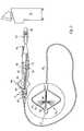
- a sheath or guide catheter 10is inserted into a blood vessel 12 that leads to the right atrium 14 of the heart 16 and passed through an opening created in the septum 18 that separates the right and left atria into the left atrium 20 .
- a treatment element 22is passed through the guide catheter 10 , deployed from an opening in the distal end thereof, and caused to form a substantially circular loop that is traverse or perpendicular to the longitudinal axis of the guide catheter 10 .
- a distal tip element 24 that extends distally beyond the circular loopis inserted into a pulmonary vein 26 as a guide and placement aid for the loop.
- the treatment element 22 in the form of a loopis placed so that it encircles the opening or entry of the pulmonary vein 26 , known as the ostium, and tissue is ablated by microwave heating of the contacted tissue.
- the intended resultis a substantially uniform circle of ablated tissue 28 as shown in FIG. 4 (prior art).
- FIG. 4prior art
- such a devicecan be used in an attempt to create linear lesions 30 and 32 as well.
- electrode elementscapable of ablating tissue when energized, are circumferentially disposed on the exterior of a balloon element that is placed at least partially within a pulmonary vein, so that the electrodes are positioned to form a circumferential conduction block along a circumferential region of tissue in a pulmonary vein wall.
- Other device configurationsare disclosed that have an electrode band positioned on an expandable member for ablating a circumferential path around the ostium and tissue along the posterior atrial wall which surrounds the pulmonary vein.
- RF energycauses cellular death and side effects that are specific to the use of RF energy and that contrast considerably with the effects of cooling and the cellular death caused by freezing tissue.
- RF ablationmay be appropriate and safe for tissue ablation in other areas of the body
- clinical studieshave revealed that creating of RF lesions in the pulmonary veins does not appear advantageous for the reasons set forth above.
- RF ablation of the pulmonary veinshas been associated with left atrial-esophageal fistula, pulmonary vein stenosis, tamponade, and significant radiation exposure. Therefore, if a cryogenic device were available as an alternative to RF ablation devices and techniques for the treatment of atrial fibrillation, it would be preferable to use the cryogenic device to avoid the problems created by the use of RF energy.
- cryoablationNotwithstanding the apparent advantages of cryoablation over other types of ablation, particularly RF, with respect to treatment of atrial fibrillation, very few cryoablation devices have been conceived for this purpose. Or, if cryoablation has been considered, it is mentioned as if it were synonymous with RF ablation, with no actual thought or disclosure provided that is enabling for such a structurally dissimilar device or that takes into account the very different effects of the use of the respective devices on tissue.
- U.S. Pat. No. 6,164,283makes a brief, generalized reference to use of a cryoablation element to cool tissue, no specific details are set forth with respect to such a device.
- the present inventionadvantageously provides a method and system for cryogenically ablating large areas of tissue within the left atrium.
- a cryotherapy devicefor modifying the electrophysiological properties of cardiac tissue having an uneven surface topography
- the deviceincludes a catheter body having a substantially fixed diameter, a proximal end and a distal end; a first lumen for permitting passage of a cooling fluid from the proximal end to the distal end; a second lumen permitting return of the cooling fluid from the distal end to the proximal end; and an ablation element expandable from a first diameter that is substantially the same as the diameter of the catheter body to a second diameter that is at least twice the diameter of the catheter body, the ablation element having a surface portion that conforms to the uneven surface topography of the cardiac tissue.
- the ablation elementcan include one or more balloons and/or a flexible element that is deformed by moving the distal end of the catheter toward the proximal end of the catheter.
- the surface of the ballooncan further be shaped by regulation of pressure within the one or more balloons.
- the inventionalso includes a method for modifying the electrophysiological properties of cardiac tissue wherein a tissue ablation device is provided and tissue in the antrum of the left atrium is ablated with the device.
- tissue ablation deviceis provided and tissue in the antrum of the left atrium is ablated with the device.
- tissue in the antrumis ablated, and the ablation is created by freezing tissue.
- an exemplary method of a cryomaze procedureis provided which can be performed without the need to arrest the heart of the patient.
- FIG. 1depicts a prior art technique for placing a distal portion of a medical device within the heart
- FIG. 2illustrates a prior art technique for positioning a prior art device within the left atrium
- FIG. 3depicts a prior art technique for creating a lesion with a prior art microwave ablation device
- FIG. 4shows lesions formed using the prior art techniques and devices of FIGS. 1 , 2 and 3 ;
- FIG. 5is a schematic illustration of a cryogenic ablation system in accordance with the present invention.
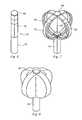
- FIG. 6is a side view of an exemplary ablation element for the system of FIG. 5 ;
- FIG. 7depicts the ablation element of FIG. 6 is an expanded state
- FIG. 8shows an alternative embodiment of the ablation element of FIG. 6 , wherein a membrane is disposed over expansion elements positioned in an expanded state;
- FIG. 9is a front view of the ablation element of FIG. 6 , wherein an ablation pattern created by the device is shown;
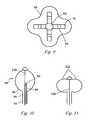
- FIG. 10illustrates an alternative embodiment for the ablation element in a partially expanded state
- FIG. 11illustrates the ablation element of FIG. 10 in a fully expanded state
- FIG. 12depicts the ablation element of FIG. 10 in a partially inflated state suitable for deflection
- FIG. 13depicts the ablation element of FIG. 10 in the partially inflated state shown in FIG. 12 being deflected to a curved configuration
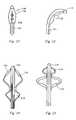
- FIG. 14shows yet another embodiment of the ablation element
- FIGS. 15-17illustrate the ablation element in exemplary deployment configurations
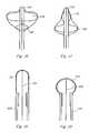
- FIG. 18illustrates yet another embodiment of an ablation element
- FIG. 19shows the ablation element of FIG. 18 in a deflected condition
- FIG. 20show yet another ablation element in accordance with the invention.
- FIG. 21illustrates an ablation device in accordance with the invention within the left atrium of the heart having created lesions in the left antral region
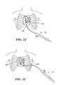
- FIG. 22illustrates a method of use of the present invention
- FIG. 23illustrates an alternative method of use of the present invention
- FIG. 24illustrates another method of use of the present invention.
- FIG. 25illustrates an additional method of use of the present invention.
- the creation of a conduction block or an interruption of the electrical signal flow path from the region of the atrium and the pulmonary veinis an effective treatment for atrial fibrillation.
- the creation of a narrow annular lesion at or very near the ostium of the pulmonary veinis an effective way to create a conduction block, notwithstanding the difficulty of making such a lesion, it is believed that creating one or more non-annular lesions in different locations is not only more readily accomplished with reliability, but it is more clinically effective.
- the present inventionprovides apparatus and methods for modifying the electrophysiological properties of large areas of tissue rather than narrow, annular lesions at locations that are not confined solely to the ostium, although ablation of tissue near the ostium and/or in the atrial wall may be included. More particularly, the present invention provides devices that are suitable to cryogenically ablate regions of tissue in the antrum region of the left atrium in addition to other atrial tissue that may be deemed to be arrhythmogenic.
- the antrumis the area between the mouth or ostium of a pulmonary vein and the atrium.
- the antrum of each pulmonary veinis not identical in size or shape and the tissue topography renders it very difficult or almost impossible to create a ring of tissue. Accordingly, the present method calls for ablating large regions of tissue in the antrum to render the tissue electrically dysfunctional.
- the systemincludes an elongate, highly flexible ablation catheter 34 that is suitable for passage through the vasculature.
- the ablation catheter 34includes a catheter body 36 having a distal end 37 with an ablation element 38 at or proximal to the distal end.
- the distal end 37 and the ablation element 38are shown magnified and are described in greater detail below.
- the ablation catheter 34has a proximal end 40 that is mated to a handle 42 that can include an element such as a lever 44 or knob for manipulating the catheter body 36 and the ablation element 38 .
- a pull wire 46 having a proximal end and a distal endhas its distal end is anchored to the catheter at or near the distal end 37 .
- the proximal end of the pull wireis anchored to an element such as a cam 48 in communication with and responsive to the lever 44 .
- the handle 42can further include circuitry 50 for identification and/or use in controlling of the ablation catheter or another component of the system.
- the handle 42can also include connectors that are matable directly to a cryogenic fluid supply/exhaust and control unit or indirectly by way of one or more umbilicals.
- the handle 42is provided with a first connector 54 that is matable with a co-axial fluid umbilical (not shown) and a second connector 56 that is matable with an electrical umbilical (not shown) that can further include an accessory box (not shown).
- the fluid supply and exhaust, as well as various control mechanisms for the systemare housed in a single console 52 .
- the consolecan also recover and/or recirculate the cooling fluid.
- the handle 42is provided with a fitting 58 for receiving a guide wire (not shown) that is passed into a guide wire lumen 60 .
- the ablation element 38is shown as a double balloon, wherein an inner balloon 62 is contained by an outer balloon 64 .
- a coolant supply tube 66 in fluid communication with the coolant supply in the console 52is provided to release coolant from one or more openings in the tube within the inner balloon 62 in response to console commands and other control input.
- a vacuum pump in the console 52creates a low pressure environment in one or more lumens within the catheter body 36 so that coolant is drawn into the lumen(s), away from the inner balloon, and toward the proximal end of the catheter body.
- the vacuum pumpis also in fluid communication with the interface of the inner and the outer balloons so that any fluid that leaks from the inner balloon is contained and aspirated. Still referring to FIG.
- the handleincludes one or more pressure sensors 68 to monitor the fluid pressure within one or both of the balloons, blood detection devices 70 and pressure relief valves 72 .
- the inner and the outer balloon 64expand to a predetermined shape to present an ablation surface, wherein the temperature of the ablation surface is determined by the material properties of the specific coolant selected for use, such as nitrous oxide, along with the pressure within the inner balloon and the coolant flow rate.
- FIGS. 6-20illustrate other configurations for the ablation element that are capable of creating wide-area ablation patterns.
- a distal catheter portion 74includes longitudinal elements 76 secured to a main catheter body 78 proximally, and to a tip element 80 , distally.
- a pull wire 82 or pushrod connected to a manipulation element 44 at the proximal end of the catheter and to the tip element 80is movable longitudinally to move the tip element longitudinally.
- Electrodes 84can be associated with one or more of the longitudinal elements for use in monitoring or evaluating electrical activity in tissue.
- each of the longitudinal elements 76are provided with coolant injection tubes 83 disposed within a lumen defined by each longitudinal element, wherein coolant is recovered in the lumen which is in fluid communication with a low pressure source.
- each of the longitudinal elements 76are cooled.
- the injection tubes 83can all be supplied with coolant simultaneously, if desired, less than all of the injection tubes can be supplied with coolant to provide selectively radial cooling.
- the longitudinal elementscan support a single or a double layer flexible member 85 that envelops them.
- coolantcan be circulated through the chamber defined by the elements and the flexible member as described with respect to FIG. 5 and the pull wire 82 can be used to deform the balloon by moving the distal end of the device proximally and distally.
- FIG. 9is a front view of the device of FIGS. 7 and 8 and it illustrates the general shape of the periphery 86 of a lesion formed by cryoablation using the exemplary device in the expanded state.
- spot or linear lesionscan be created when the distal catheter portion 74 is in the non-expanded state illustrated in FIG. 6 .
- a catheteris provided with an ablation element 88 similar to the double balloon structure of FIG. 5 so that a distal tip region 90 is radially expandable to at least double the diameter of a catheter body 92 over a 2 cm to 3 cm length.
- the ablation element 88is provided with a cryogenic fluid injection tube 94 having one or more fluid outlets 96 along its length in the distal tip region. Coolant is withdrawn though an outer lumen 98 at reduced pressure.
- a pull wire 100 or pushrodis used to deflect the distal catheter portion as shown in FIG. 11 so that a large, distal facing surface 102 can be placed into contact with tissue.
- the catheter 10has a substantially greater radius than the catheter body 92 , when the pull wire 100 is used to draw the distal tip toward the catheter body as shown in FIG. 11 , the balloon expands even further and presents a flattened tip that is suitable to blot large areas of tissue.
- an ablation element 104is provided with a distal portion 106 that is inflatable, one or more coolant injection orifices 108 and an exhaust lumen 110 .
- the ablation element 104is shown with a pull wire 111 or pushrod connected to a manipulation element at the proximal end of the catheter and the tip element 12 so as to be movable longitudinally to deflect the tip element off axis.
- the ablation elementcan be provided with a notch 114 to accommodate or fit over a ridge of tissue.
- FIGS. 14-17illustrate an embodiment for an ablation element, wherein first and second balloons, 116 and 118 , respectively, are enveloped by a third balloon 120 .
- the first and the second balloons 116 and 118are in fluid communication with inflation and exhaust lumens as described above, wherein the third balloon 120 is only in communication with a vacuum or low pressure source.
- Each of the first and second balloonsis provided with a shape and/or is pressurized to provide an overall surface topography for the ablation element. Additional shaping is provided by manipulation of a pull wire as described above or by regulation of the pressure in the exhaust flow path.
- an ablation elementincludes an elastically deformable, thermally-transmissive tip element 122 secured to the distal portion of a catheter body 124 .
- a loadis applied to the tip element 122 it deforms.
- FIG. 19illustrates the tip element subject to an axial load, such as is encountered when the tip is pressed against tissue.
- the distal portion of the tip element 122presents a wider ablation surface when deflected as compared to the non deflected state.
- Fluid supply and exhaust lumensare provided as disclosed above.
- a pull wire 125can be secured to the tip element 122 to help deform the element so that it doesn't need to be pressed hard against tissue.
- the tip element 122is configured so that it is biased into the shape illustrated in FIG. 18 .
- Proximal tensionis applied to the pull wire 125 to deform or aid in deforming the tip element to an expanded configuration as shown in FIG. 19 .
- the biasing force of the tip elementcauses it to return to the configuration shown in FIG. 18 .
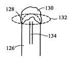
- FIG. 20illustrates yet another configuration of an ablation element wherein a catheter body 126 has a distal end 128 covered with a mass of thermally conductive, highly elastic material, such as a cohesive gel 130 .
- a catheter body 126has a distal end 128 covered with a mass of thermally conductive, highly elastic material, such as a cohesive gel 130 .
- the geldeforms to provide an enlarged distal end portion as shown by the dashed line 132 .
- Coolant exiting a coolant supply tube 134cools the distal end 128 and the gel 130 .
- the ablation element 136is a balloon that is partially inflated with a nitrous oxide coolant so that it has a “squishy” or highly compliant character and dimensioned so that it can “blot” or contact an area of tissue approximately 28 to 30 mm in diameter.
- the balloonis inflated to the desired degree of firmness, or lack thereof, before being advanced toward tissue and the balloon's surface is chilled to a temperature in the range of minus 30 degrees Centigrade to minus 80 degrees Centigrade.
- the balloonis then placed into contact with tissue in the antrum 138 and the tissue is ablated.
- the balloonis moved to one or more additional areas of the antrum 138 until the desired tissue modification has been achieved.
- the ballooncan be placed so as to create individual distinct lesions or overlapping lesions. In this fashion, large contiguous lesions can be created.
- the pattern 139 shown in FIG. 21illustrates an exemplary lesion periphery created with the ablation element 136 .
- the balloondoes not have to be centered on the ostium 140 and no anchoring is needed.
- precise alignmentis not as important as with respect to other devices. This is significant, because the precise positioning within the antrum is difficult to achieve.
- the balloondoes not enter the pulmonary vein 142 . However, depending upon placement of the balloon, the temperature achieved, and the duration that the balloon is left in place, is possible to ablate tissue in the ostium 140 in addition to tissue within the pulmonary vein 142 , as well as the antrum 138 .
- the ablation catheter 34 as described abovemay be used to create a series of lesions in the heart, whereby the ablation catheter is maneuvered into the left atrium of the heart for treatment of an arrhythmia or other cardiac abnormality.
- the ablation cathetermay be positioned in proximity to the heart using one of either a subxyphoid approach, a thoracotomy approach, or a sternotomy method. Each of these methods provides surgical access to the heart for subsequent positioning and insertion into the left atrium of a medical device for ablation of the desired tissue.
- the heart 200may initially be accessed through a puncture technique using the same 17-Gauge Tuohy needle that is used to enter the epidural space when administering epidural anesthesia (typically .about. 100 mm overall length, and 1.5 mm O.D.).
- a subxyphoid incision 202which is typically less than 10 centimeters in length, is created.
- small amounts of contrast mediaare injected to document penetration of the needle tip as it progresses towards the heart.
- a guide wiremay be passed through the needle.
- a standard introducer sheath, and subsequently an ablation catheter 34may be passed into a position in proximity to the heart 200 .
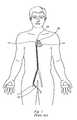
- a thoracotomy techniquemay also be performed for providing initial access the heart 200 , whereby one or more small thoracotomy incisions 204 are made in the chest wall between the ribs to permit access for thoracoscopic instruments and cameras, which provide dissection and visualization capabilities in the pericardial space for insertion and manipulation of medical instruments, including the ablation catheter.
- the small thoracotomy incisionsare typically less than 10 centimeters in length. In this approach, the decompression of the pleural space may be necessary in order to achieve pericardial access.
- a third approachemploys a sternotomy, which is commonly performed for open heart surgery, and is the least minimally-invasive of the approaches described above.
- a full sternotomymay include multiple incisions and the eventual division of the sternum, thereby providing direct access to the heart 200 .
- the ablation catheterUpon generally accessing the heart through any of the above-mentioned approaches, the ablation catheter must further enter the internal chambers of the heart for the eventual ablation of the desired tissue. Such internal access may be achieved by directing the ablation catheter through one of the pulmonary veins or the aorta, through the heart tissue or left atrial appendage, or through the superior vena cava and the septum wall.
- a pursestring suturemay be placed in any of the pulmonary veins or the aorta.
- an introducermay be inserted through the pulmonary veins or aorta, and into the left atrium. Once the introducer is appropriately positioned, the ablation catheter may be guided through the introducer and into the left atrium for subsequent ablation of the desired tissue.
- Access to the internal chambers of the heartmay further be accomplished directly through an exterior surface of the heart, or through the left atrial appendage.
- a pursestring suturemay be placed in the left atrial appendage, through which an introducer and/or guidewire is positioned.
- the ablation cathetermay be guided directly into the left atrium through the left atrial appendage or other exterior heart surface for subsequent ablation of the desired tissue within the heart.
- the internal chambers of the heartmay additionally be accessed by a transseptal approach.
- a transseptal approachmay include placing a pursestring suture in the lateral wall of the right atrium, providing access for a needle to further be inserted into the heart.
- the needle, as well as a guidewire and introducermay be initially guided into the right atrium through the superior vena cava. Further, the needle may be maneuvered through the atrial septum and into the left atrium, at which point the guide wire may be inserted to dilate the opening in the atrial septum.
- the introducermay be directed through the septum and into the left atrium. Subsequently, the ablation catheter may be guided through the introducer and into the left atrium for ablation of the desired tissue.
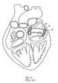
- the ablation cathetercan be positioned in the orifice of the right inferior pulmonary vein, possibly employing the aid of fluoroscopy or other medical imaging to facilitate accurate placement of the device. Positioning and occlusion of the vein orifice may further be confirmed through the administration of a contrast dye.
- the ablation cathetercan be used to create a lesion around the orifice of the right inferior pulmonary vein. The ablation catheter may then be repositioned in the right superior vein, the left superior vein, and the left inferior pulmonary vein for the creation of additional ablative lesions about the orifices of the respective vessels. An additional lesion may be created to connect the lesions of the left-sided pulmonary veins with the lesions of the right-sided pulmonary veins, to form somewhat of an “eyeglass” pattern.
- one or more lesionsextending from the left inferior pulmonary vein to the mitral valve annulus can be created using the ablation catheter.
- a pacing catheter or other electrical-sensing devicecan be used to monitor electrical pulses in the affected tissue, and ablation may be reinstituted in the desired locations, if necessary.
- While ablation proceduresare typically performed on an arrested heart, the procedure described above may be performed with the ablation catheter on a beating heart employing a thoracoscopic or small thoracotomy approach, which reduces the recovery time for a patient as well as reducing the complexity of the surgical procedure.
- the higher-risk portions of a typical maze procedurenamely a sternotomy, cardiopulmonary bypass, and/or aortic cross-clamping or cardiac arrest, are no longer necessary.
- the ablation catheter used to create the lesions described abovemay include any of the features previously discussed. Moreover, in order to ease the use of the catheter in the transseptal approach, the length of a portion of the catheter may be reduced from that of a standard catheter inserted into the femoral artery or other insertion point distant from the heart. Furthermore, the flexibility of the portions of the catheter may be altered in order to provide increased malleability in order to facilitate the accurate positioning of the ablation element within the heart. Alternatively, pull-wires or other deflection mechanisms can be integrated with or otherwise coupled with the catheter for steering and/or positioning, as is known in the art.
Landscapes
- Health & Medical Sciences (AREA)
- Surgery (AREA)
- Life Sciences & Earth Sciences (AREA)
- Nuclear Medicine, Radiotherapy & Molecular Imaging (AREA)
- Biomedical Technology (AREA)
- Engineering & Computer Science (AREA)
- Otolaryngology (AREA)
- Heart & Thoracic Surgery (AREA)
- Medical Informatics (AREA)
- Molecular Biology (AREA)
- Animal Behavior & Ethology (AREA)
- General Health & Medical Sciences (AREA)
- Public Health (AREA)
- Veterinary Medicine (AREA)
- Surgical Instruments (AREA)
Abstract
Description
Claims (13)
Priority Applications (1)
| Application Number | Priority Date | Filing Date | Title |
|---|---|---|---|
| US11/184,045US7740627B2 (en) | 2005-04-29 | 2006-01-06 | Surgical method and apparatus for treating atrial fibrillation |
Applications Claiming Priority (2)
| Application Number | Priority Date | Filing Date | Title |
|---|---|---|---|
| US11/119,399US7794455B2 (en) | 2005-04-29 | 2005-04-29 | Wide area ablation of myocardial tissue |
| US11/184,045US7740627B2 (en) | 2005-04-29 | 2006-01-06 | Surgical method and apparatus for treating atrial fibrillation |
Related Parent Applications (1)
| Application Number | Title | Priority Date | Filing Date |
|---|---|---|---|
| US11/119,399Continuation-In-PartUS7794455B2 (en) | 2005-04-29 | 2005-04-29 | Wide area ablation of myocardial tissue |
Publications (2)
| Publication Number | Publication Date |
|---|---|
| US20080243111A1 US20080243111A1 (en) | 2008-10-02 |
| US7740627B2true US7740627B2 (en) | 2010-06-22 |
Family
ID=39795646
Family Applications (1)
| Application Number | Title | Priority Date | Filing Date |
|---|---|---|---|
| US11/184,045Active2027-12-13US7740627B2 (en) | 2005-04-29 | 2006-01-06 | Surgical method and apparatus for treating atrial fibrillation |
Country Status (1)
| Country | Link |
|---|---|
| US (1) | US7740627B2 (en) |
Cited By (37)
| Publication number | Priority date | Publication date | Assignee | Title |
|---|---|---|---|---|
| US20060084962A1 (en)* | 2004-06-02 | 2006-04-20 | Cryovascular Systems, Inc. | Controllable pressure cryogenic balloon treatment system and method |
| US20060270981A1 (en)* | 2005-05-13 | 2006-11-30 | Leonilda Capuano | Coiled injection tube |
| US20080091180A1 (en)* | 2005-04-29 | 2008-04-17 | Cryocath Technologies Inc. | Wide area ablation of myocardial tissue |
| US20090118723A1 (en)* | 2005-05-13 | 2009-05-07 | Jean-Pierre Lalonde | Coolant injection tube |
| US20110190751A1 (en)* | 2010-02-01 | 2011-08-04 | Boston Scientific Scimed, Inc. | Nested balloon cryotherapy |
| US8663122B2 (en) | 2005-01-26 | 2014-03-04 | Stuart Schecter LLC | Cardiovascular haptic handle system |
| US20140257261A1 (en)* | 2009-08-14 | 2014-09-11 | Boston Scientific Scimed, Inc. | Systems and methods for making and using medical ablation systems having mapping catheters with improved anchoring ability |
| US8942828B1 (en) | 2011-04-13 | 2015-01-27 | Stuart Schecter, LLC | Minimally invasive cardiovascular support system with true haptic coupling |
| US9026190B2 (en) | 2010-11-17 | 2015-05-05 | Rhythm Check, Inc. | Portable physiological parameter detection and monitoring device with integratable computer memory and communication disk, systems and methods of use thereof |
| US9113911B2 (en) | 2012-09-06 | 2015-08-25 | Medtronic Ablation Frontiers Llc | Ablation device and method for electroporating tissue cells |
| US9387031B2 (en) | 2011-07-29 | 2016-07-12 | Medtronic Ablation Frontiers Llc | Mesh-overlayed ablation and mapping device |
| US9636172B2 (en) | 2013-05-31 | 2017-05-02 | Medtronic Cryocath Lp | Compliant balloon with liquid injection |
| US9993280B2 (en) | 2015-07-02 | 2018-06-12 | Medtronic Cryocath Lp | N2O thermal pressurization system by cooling |
| US10013082B2 (en) | 2012-06-05 | 2018-07-03 | Stuart Schecter, LLC | Operating system with haptic interface for minimally invasive, hand-held surgical instrument |
| US10028781B2 (en) | 2013-09-30 | 2018-07-24 | Arrinex, Inc. | Apparatus and methods for treating rhinitis |
| US10159538B2 (en) | 2014-07-25 | 2018-12-25 | Arrinex, Inc. | Apparatus and method for treating rhinitis |
| US10342608B2 (en) | 2012-10-18 | 2019-07-09 | The Board Of Trustees Of The Leland Stanford Junior University | Ablation catheter system and method for deploying same |
| US10433894B2 (en) | 2015-07-02 | 2019-10-08 | Medtronic Cryocath Lp | N2O liquefaction system with subcooling heat exchanger for medical device |
| US10543032B2 (en) | 2014-11-13 | 2020-01-28 | Adagio Medical, Inc. | Pressure modulated cryoablation system and related methods |
| US10617459B2 (en) | 2014-04-17 | 2020-04-14 | Adagio Medical, Inc. | Endovascular near critical fluid based cryoablation catheter having plurality of preformed treatment shapes |
| US10631840B2 (en) | 2015-11-25 | 2020-04-28 | Talon Medical, LLC | Tissue engagement devices, systems, and methods |
| US10667854B2 (en) | 2013-09-24 | 2020-06-02 | Adagio Medical, Inc. | Endovascular near critical fluid based cryoablation catheter and related methods |
| US10864031B2 (en) | 2015-11-30 | 2020-12-15 | Adagio Medical, Inc. | Ablation method for creating elongate continuous lesions enclosing multiple vessel entries |
| US10939965B1 (en) | 2016-07-20 | 2021-03-09 | Arrinex, Inc. | Devices and methods for treating a nerve of the nasal cavity using image guidance |
| US11026738B2 (en) | 2016-06-15 | 2021-06-08 | Arrinex, Inc. | Devices and methods for treating a lateral surface of a nasal cavity |
| US11051867B2 (en) | 2015-09-18 | 2021-07-06 | Adagio Medical, Inc. | Tissue contact verification system |
| US11253312B2 (en) | 2016-10-17 | 2022-02-22 | Arrinex, Inc. | Integrated nasal nerve detector ablation-apparatus, nasal nerve locator, and methods of use |
| US11278356B2 (en) | 2017-04-28 | 2022-03-22 | Arrinex, Inc. | Systems and methods for locating blood vessels in the treatment of rhinitis |
| US11331140B2 (en) | 2016-05-19 | 2022-05-17 | Aqua Heart, Inc. | Heated vapor ablation systems and methods for treating cardiac conditions |
| US11517319B2 (en) | 2017-09-23 | 2022-12-06 | Universität Zürich | Medical occluder device |
| US11564725B2 (en) | 2017-09-05 | 2023-01-31 | Adagio Medical, Inc. | Ablation catheter having a shape memory stylet |
| US11589920B2 (en) | 2008-10-06 | 2023-02-28 | Santa Anna Tech Llc | Catheter with a double balloon structure to generate and apply an ablative zone to tissue |
| US11602260B2 (en) | 2016-02-11 | 2023-03-14 | Arrinex, Inc. | Method and device for image guided post-nasal nerve ablation |
| US11751930B2 (en) | 2018-01-10 | 2023-09-12 | Adagio Medical, Inc. | Cryoablation element with conductive liner |
| US11944315B2 (en) | 2019-09-26 | 2024-04-02 | Universität Zürich | Left atrial appendage occlusion devices |
| US12364537B2 (en) | 2016-05-02 | 2025-07-22 | Santa Anna Tech Llc | Catheter with a double balloon structure to generate and apply a heated ablative zone to tissue |
| US12402885B2 (en) | 2017-09-23 | 2025-09-02 | Universität Zürich | Medical occlusion device |
Families Citing this family (18)
| Publication number | Priority date | Publication date | Assignee | Title |
|---|---|---|---|---|
| US8961541B2 (en) | 2007-12-03 | 2015-02-24 | Cardio Vascular Technologies Inc. | Vascular closure devices, systems, and methods of use |
| US20080109030A1 (en) | 2001-04-24 | 2008-05-08 | Houser Russell A | Arteriotomy closure devices and techniques |
| US8992567B1 (en) | 2001-04-24 | 2015-03-31 | Cardiovascular Technologies Inc. | Compressible, deformable, or deflectable tissue closure devices and method of manufacture |
| WO2010071810A1 (en) | 2008-12-19 | 2010-06-24 | Andy Christopher Kiser | Methods and devices for endoscopic access to the heart |
| WO2010083281A1 (en)* | 2009-01-15 | 2010-07-22 | Boston Scientific Scimed, Inc. | Controlling depth of cryoablation |
| EP2416711A4 (en) | 2009-04-09 | 2017-06-07 | Cardiovascular Technologies, Inc. | Tissue closure devices, device and systems for delivery, kits and methods therefor |
| US8926602B2 (en)* | 2010-01-28 | 2015-01-06 | Medtronic Cryocath Lp | Triple balloon catheter |
| US9820803B2 (en) | 2010-04-28 | 2017-11-21 | Medtronic, Inc. | Subxiphoid connective lesion ablation system and method |
| US8679105B2 (en)* | 2010-07-28 | 2014-03-25 | Medtronic Cryocath Lp | Device and method for pulmonary vein isolation |
| US8911434B2 (en) | 2010-10-22 | 2014-12-16 | Medtronic Cryocath Lp | Balloon catheter with deformable fluid delivery conduit |
| US20120283714A1 (en)* | 2011-05-02 | 2012-11-08 | Teresa Ann Mihalik | Methods of treatment with compliant elements and wire structures |
| US20120283713A1 (en)* | 2011-05-02 | 2012-11-08 | Teresa Ann Mihalik | Compliant sleeves coupled with wire structures for cryoablation |
| CN103619274A (en)* | 2011-05-02 | 2014-03-05 | 美敦力 | Compliant cannula with attached wire structure for cryoablation |
| WO2013013099A1 (en)* | 2011-07-19 | 2013-01-24 | Adagio Medical, Inc. | Methods and devices for the treatment of atrial fibrillation |
| US10398488B2 (en) | 2014-09-04 | 2019-09-03 | Medtronic Cryocath Lp | Cryoadhesive device for left atrial appendage occlusion |
| US10123786B2 (en)* | 2016-09-16 | 2018-11-13 | Krishna Rocha-Singh, M.D. | Bone marrow harvesting device |
| US12220157B2 (en) | 2017-06-05 | 2025-02-11 | St. Jude Medical, Cardiology Division, Inc. | Pulmonary antrum radial-linear ablation devices |
| CN108784896B (en)* | 2017-10-31 | 2024-04-05 | 杭州诺生医疗科技有限公司 | Interatrial ostomy device, interatrial ostomy system and method of operating the same |
Citations (53)
| Publication number | Priority date | Publication date | Assignee | Title |
|---|---|---|---|---|
| US5472441A (en)* | 1993-11-08 | 1995-12-05 | Zomed International | Device for treating cancer and non-malignant tumors and methods |
| US5487385A (en) | 1993-12-03 | 1996-01-30 | Avitall; Boaz | Atrial mapping and ablation catheter system |
| US5575766A (en) | 1993-11-03 | 1996-11-19 | Daig Corporation | Process for the nonsurgical mapping and treatment of atrial arrhythmia using catheters guided by shaped guiding introducers |
| US5584803A (en)* | 1991-07-16 | 1996-12-17 | Heartport, Inc. | System for cardiac procedures |
| US5673695A (en) | 1995-08-02 | 1997-10-07 | Ep Technologies, Inc. | Methods for locating and ablating accessory pathways in the heart |
| US5682906A (en) | 1993-02-22 | 1997-11-04 | Heartport, Inc. | Methods of performing intracardiac procedures on an arrested heart |
| US5752526A (en) | 1996-02-19 | 1998-05-19 | The Cleveland Clinic Foundation | Minimally invasive cardiac surgery procedure |
| US5855614A (en) | 1993-02-22 | 1999-01-05 | Heartport, Inc. | Method and apparatus for thoracoscopic intracardiac procedures |
| US5938660A (en) | 1997-06-27 | 1999-08-17 | Daig Corporation | Process and device for the treatment of atrial arrhythmia |
| US5971979A (en) | 1997-12-02 | 1999-10-26 | Odyssey Technologies, Inc. | Method for cryogenic inhibition of hyperplasia |
| US6012457A (en) | 1997-07-08 | 2000-01-11 | The Regents Of The University Of California | Device and method for forming a circumferential conduction block in a pulmonary vein |
| WO2000007657A1 (en) | 1998-08-04 | 2000-02-17 | Percusurge, Inc. | Low profile for angioplasty and occlusion catheter |
| US6161543A (en)* | 1993-02-22 | 2000-12-19 | Epicor, Inc. | Methods of epicardial ablation for creating a lesion around the pulmonary veins |
| US6164283A (en) | 1997-07-08 | 2000-12-26 | The Regents Of The University Of California | Device and method for forming a circumferential conduction block in a pulmonary vein |
| US6199556B1 (en) | 1998-05-01 | 2001-03-13 | Cardiothoracic Systems, Inc. | Xyphoid access for cardiac surgical procedures |
| US6214002B1 (en) | 1994-10-07 | 2001-04-10 | Ep Technologies, Inc. | Structures and methods for deploying electrode elements |
| US6233491B1 (en) | 1993-03-16 | 2001-05-15 | Ep Technologies, Inc. | Cardiac mapping and ablation systems |
| US6241754B1 (en) | 1993-10-15 | 2001-06-05 | Ep Technologies, Inc. | Composite structures and methods for ablating tissue to form complex lesion patterns in the treatment of cardiac conditions and the like |
| US6245064B1 (en) | 1997-07-08 | 2001-06-12 | Atrionix, Inc. | Circumferential ablation device assembly |
| US6283127B1 (en) | 1992-12-03 | 2001-09-04 | Wesley D. Sterman | Devices and methods for intracardiac procedures |
| US6283959B1 (en) | 1999-08-23 | 2001-09-04 | Cyrocath Technologies, Inc. | Endovascular cryotreatment catheter |
| US6290696B1 (en) | 1997-03-06 | 2001-09-18 | Scimed Life Systems, Inc. | Cryoplasty device and method |
| US6325797B1 (en) | 1999-04-05 | 2001-12-04 | Medtronic, Inc. | Ablation catheter and method for isolating a pulmonary vein |
| WO2002007628A2 (en) | 2000-07-19 | 2002-01-31 | Cryovascular Systems, Inc. | Improved safety cryotherapy catheter |
| US20020087151A1 (en)* | 2000-12-29 | 2002-07-04 | Afx, Inc. | Tissue ablation apparatus with a sliding ablation instrument and method |
| US6416511B1 (en) | 1997-05-09 | 2002-07-09 | The Regents Of The University Of California | Circumferential ablation device assembly |
| WO2002083196A2 (en) | 2001-04-12 | 2002-10-24 | Boston Scientific Limited, An Irish Compagny | Cryo balloon for atrial ablation |
| US6585733B2 (en)* | 2001-09-28 | 2003-07-01 | Ethicon, Inc. | Surgical treatment for atrial fibrillation using radiofrequency technology |
| US20030125721A1 (en) | 1998-03-31 | 2003-07-03 | Yon Steven A. | Method and device for performing cooling or cryo-therapies, for, e.g., angioplasty with reduced restenosis or pulmonary vein cell necrosis to inhibit atrial fibrillation employing tissue protection |
| US6602276B2 (en) | 1998-03-31 | 2003-08-05 | Innercool Therapies, Inc. | Method and device for performing cooling- or cryo-therapies for, e.g., angioplasty with reduced restenosis or pulmonary vein cell necrosis to inhibit atrial fibrillation |
| US6638237B1 (en) | 1999-08-04 | 2003-10-28 | Percardia, Inc. | Left ventricular conduits and methods for delivery |
| US6651670B2 (en) | 1998-02-13 | 2003-11-25 | Ventrica, Inc. | Delivering a conduit into a heart wall to place a coronary vessel in communication with a heart chamber and removing tissue from the vessel or heart wall to facilitate such communication |
| US6652515B1 (en) | 1997-07-08 | 2003-11-25 | Atrionix, Inc. | Tissue ablation device assembly and method for electrically isolating a pulmonary vein ostium from an atrial wall |
| US6651671B1 (en) | 1993-02-22 | 2003-11-25 | Heartport, Inc. | Lens-invasive devices and methods for cardiac valve surgery |
| US6672312B2 (en) | 2001-01-31 | 2004-01-06 | Transurgical, Inc. | Pulmonary vein ablation with myocardial tissue locating |
| US6685732B2 (en)* | 1998-03-31 | 2004-02-03 | Innercool Therapies, Inc. | Method and device for performing cooling- or cryo-therapies for, e.g., angioplasty with reduced restenosis or pulmonary vein cell necrosis to inhibit atrial fibrillation employing microporous balloon |
| US6689128B2 (en)* | 1996-10-22 | 2004-02-10 | Epicor Medical, Inc. | Methods and devices for ablation |
| US6743225B2 (en) | 2001-03-27 | 2004-06-01 | Uab Research Foundation | Electrophysiologic measure of endpoints for ablation lesions created in fibrillating substrates |
| US6755822B2 (en) | 2001-06-01 | 2004-06-29 | Cryocor, Inc. | Device and method for the creation of a circumferential cryogenic lesion in a pulmonary vein |
| US6758847B2 (en) | 1997-07-08 | 2004-07-06 | Atrionix, Inc. | Circumferential ablation device assembly and methods of use and manufacture providing an ablative circumferential band along an expandable member |
| US6760620B2 (en) | 2000-03-15 | 2004-07-06 | Resolution Medical, Inc. | Non-invasive localization and treatment of focal atrial fibrillation |
| US20040225342A1 (en) | 2001-05-31 | 2004-11-11 | Radiant Medical, Inc. | Moving heat exchange catheter system |
| US6817999B2 (en) | 2002-01-03 | 2004-11-16 | Afx, Inc. | Flexible device for ablation of biological tissue |
| US20050010201A1 (en) | 2003-07-11 | 2005-01-13 | Marwan Abboud | Method and device for epicardial ablation |
| US20050020901A1 (en)* | 2000-04-03 | 2005-01-27 | Neoguide Systems, Inc., A Delaware Corporation | Apparatus and methods for facilitating treatment of tissue via improved delivery of energy based and non-energy based modalities |
| US6893436B2 (en) | 2002-01-03 | 2005-05-17 | Afx, Inc. | Ablation instrument having a flexible distal portion |
| US6929639B2 (en) | 2002-08-30 | 2005-08-16 | Scimed Life Systems, Inc. | Cryo ablation coil |
| US20050182395A1 (en)* | 2002-04-19 | 2005-08-18 | Scimed Life Systems, Inc. | Cryo balloon |
| US6949095B2 (en) | 1996-10-22 | 2005-09-27 | Epicor Medical, Inc. | Apparatus and method for diagnosis and therapy of electrophysiological disease |
| WO2005089853A1 (en) | 2004-03-23 | 2005-09-29 | Cryocath Technologies Inc. | Method and apparatus for inflating and deflating balloon catheters |
| US7137395B2 (en)* | 2000-02-29 | 2006-11-21 | The Johns Hopkins University | Circumferential pulmonary vein ablation using a laser and fiberoptic balloon catheter |
| US20060271032A1 (en)* | 2005-05-26 | 2006-11-30 | Chin Albert K | Ablation instruments and methods for performing abalation |
| US7226446B1 (en)* | 1999-05-04 | 2007-06-05 | Dinesh Mody | Surgical microwave ablation assembly |
Family Cites Families (1)
| Publication number | Priority date | Publication date | Assignee | Title |
|---|---|---|---|---|
| US6641511B2 (en)* | 2000-08-31 | 2003-11-04 | Hurco Companies, Inc. | Movable arm activated tool changer for machine tool system |
- 2006
- 2006-01-06USUS11/184,045patent/US7740627B2/enactiveActive
Patent Citations (62)
| Publication number | Priority date | Publication date | Assignee | Title |
|---|---|---|---|---|
| US5584803A (en)* | 1991-07-16 | 1996-12-17 | Heartport, Inc. | System for cardiac procedures |
| US6283127B1 (en) | 1992-12-03 | 2001-09-04 | Wesley D. Sterman | Devices and methods for intracardiac procedures |
| US6651671B1 (en) | 1993-02-22 | 2003-11-25 | Heartport, Inc. | Lens-invasive devices and methods for cardiac valve surgery |
| US6679268B2 (en) | 1993-02-22 | 2004-01-20 | Heartport, Inc. | Method and apparatus for thoracoscopic intracardiac procedures |
| US6161543A (en)* | 1993-02-22 | 2000-12-19 | Epicor, Inc. | Methods of epicardial ablation for creating a lesion around the pulmonary veins |
| US5682906A (en) | 1993-02-22 | 1997-11-04 | Heartport, Inc. | Methods of performing intracardiac procedures on an arrested heart |
| US6401720B1 (en) | 1993-02-22 | 2002-06-11 | John H. Stevens | Method and apparatus for thoracoscopic intracardiac procedures |
| US5855614A (en) | 1993-02-22 | 1999-01-05 | Heartport, Inc. | Method and apparatus for thoracoscopic intracardiac procedures |
| US5924424A (en) | 1993-02-22 | 1999-07-20 | Heartport, Inc. | Method and apparatus for thoracoscopic intracardiac procedures |
| US6233491B1 (en) | 1993-03-16 | 2001-05-15 | Ep Technologies, Inc. | Cardiac mapping and ablation systems |
| US6241754B1 (en) | 1993-10-15 | 2001-06-05 | Ep Technologies, Inc. | Composite structures and methods for ablating tissue to form complex lesion patterns in the treatment of cardiac conditions and the like |
| US5575766A (en) | 1993-11-03 | 1996-11-19 | Daig Corporation | Process for the nonsurgical mapping and treatment of atrial arrhythmia using catheters guided by shaped guiding introducers |
| US5472441A (en)* | 1993-11-08 | 1995-12-05 | Zomed International | Device for treating cancer and non-malignant tumors and methods |
| US5487385A (en) | 1993-12-03 | 1996-01-30 | Avitall; Boaz | Atrial mapping and ablation catheter system |
| US6214002B1 (en) | 1994-10-07 | 2001-04-10 | Ep Technologies, Inc. | Structures and methods for deploying electrode elements |
| US5673695A (en) | 1995-08-02 | 1997-10-07 | Ep Technologies, Inc. | Methods for locating and ablating accessory pathways in the heart |
| US5752526A (en) | 1996-02-19 | 1998-05-19 | The Cleveland Clinic Foundation | Minimally invasive cardiac surgery procedure |
| US6689128B2 (en)* | 1996-10-22 | 2004-02-10 | Epicor Medical, Inc. | Methods and devices for ablation |
| US6949095B2 (en) | 1996-10-22 | 2005-09-27 | Epicor Medical, Inc. | Apparatus and method for diagnosis and therapy of electrophysiological disease |
| US20020017306A1 (en) | 1996-10-22 | 2002-02-14 | Epicor, Inc. | Surgical system and procedure for treatment of medically refractory atrial fibrillation |
| US6648878B2 (en) | 1997-03-06 | 2003-11-18 | Scimed Life Systems, Inc. | Cryoplasty device and method |
| US6290696B1 (en) | 1997-03-06 | 2001-09-18 | Scimed Life Systems, Inc. | Cryoplasty device and method |
| US6955173B2 (en) | 1997-05-09 | 2005-10-18 | The Regents Of The University Of California | Device and method for forming a circumferential conduction block in a pulmonary vein |
| US6416511B1 (en) | 1997-05-09 | 2002-07-09 | The Regents Of The University Of California | Circumferential ablation device assembly |
| US5938660A (en) | 1997-06-27 | 1999-08-17 | Daig Corporation | Process and device for the treatment of atrial arrhythmia |
| US6502576B1 (en) | 1997-07-08 | 2003-01-07 | The Regents Of The University Of California | Device and method for forming a circumferential conduction block in a pulmonary vein |
| US6758847B2 (en) | 1997-07-08 | 2004-07-06 | Atrionix, Inc. | Circumferential ablation device assembly and methods of use and manufacture providing an ablative circumferential band along an expandable member |
| US6164283A (en) | 1997-07-08 | 2000-12-26 | The Regents Of The University Of California | Device and method for forming a circumferential conduction block in a pulmonary vein |
| US6652515B1 (en) | 1997-07-08 | 2003-11-25 | Atrionix, Inc. | Tissue ablation device assembly and method for electrically isolating a pulmonary vein ostium from an atrial wall |
| US6305378B1 (en) | 1997-07-08 | 2001-10-23 | The Regents Of The University Of California | Device and method for forming a circumferential conduction block in a pulmonary vein |
| US6245064B1 (en) | 1997-07-08 | 2001-06-12 | Atrionix, Inc. | Circumferential ablation device assembly |
| US6012457A (en) | 1997-07-08 | 2000-01-11 | The Regents Of The University Of California | Device and method for forming a circumferential conduction block in a pulmonary vein |
| US5971979A (en) | 1997-12-02 | 1999-10-26 | Odyssey Technologies, Inc. | Method for cryogenic inhibition of hyperplasia |
| US6651670B2 (en) | 1998-02-13 | 2003-11-25 | Ventrica, Inc. | Delivering a conduit into a heart wall to place a coronary vessel in communication with a heart chamber and removing tissue from the vessel or heart wall to facilitate such communication |
| US20030125721A1 (en) | 1998-03-31 | 2003-07-03 | Yon Steven A. | Method and device for performing cooling or cryo-therapies, for, e.g., angioplasty with reduced restenosis or pulmonary vein cell necrosis to inhibit atrial fibrillation employing tissue protection |
| US6602276B2 (en) | 1998-03-31 | 2003-08-05 | Innercool Therapies, Inc. | Method and device for performing cooling- or cryo-therapies for, e.g., angioplasty with reduced restenosis or pulmonary vein cell necrosis to inhibit atrial fibrillation |
| US6685732B2 (en)* | 1998-03-31 | 2004-02-03 | Innercool Therapies, Inc. | Method and device for performing cooling- or cryo-therapies for, e.g., angioplasty with reduced restenosis or pulmonary vein cell necrosis to inhibit atrial fibrillation employing microporous balloon |
| US6736774B2 (en) | 1998-05-01 | 2004-05-18 | Cardiothoracic Systems, Inc. | Xyphoid access for cardiac surgical procedures |
| US6199556B1 (en) | 1998-05-01 | 2001-03-13 | Cardiothoracic Systems, Inc. | Xyphoid access for cardiac surgical procedures |
| WO2000007657A1 (en) | 1998-08-04 | 2000-02-17 | Percusurge, Inc. | Low profile for angioplasty and occlusion catheter |
| US6325797B1 (en) | 1999-04-05 | 2001-12-04 | Medtronic, Inc. | Ablation catheter and method for isolating a pulmonary vein |
| US7226446B1 (en)* | 1999-05-04 | 2007-06-05 | Dinesh Mody | Surgical microwave ablation assembly |
| US6638237B1 (en) | 1999-08-04 | 2003-10-28 | Percardia, Inc. | Left ventricular conduits and methods for delivery |
| US6283959B1 (en) | 1999-08-23 | 2001-09-04 | Cyrocath Technologies, Inc. | Endovascular cryotreatment catheter |
| US7137395B2 (en)* | 2000-02-29 | 2006-11-21 | The Johns Hopkins University | Circumferential pulmonary vein ablation using a laser and fiberoptic balloon catheter |
| US6760620B2 (en) | 2000-03-15 | 2004-07-06 | Resolution Medical, Inc. | Non-invasive localization and treatment of focal atrial fibrillation |
| US20050020901A1 (en)* | 2000-04-03 | 2005-01-27 | Neoguide Systems, Inc., A Delaware Corporation | Apparatus and methods for facilitating treatment of tissue via improved delivery of energy based and non-energy based modalities |
| WO2002007628A2 (en) | 2000-07-19 | 2002-01-31 | Cryovascular Systems, Inc. | Improved safety cryotherapy catheter |
| US20020087151A1 (en)* | 2000-12-29 | 2002-07-04 | Afx, Inc. | Tissue ablation apparatus with a sliding ablation instrument and method |
| US6672312B2 (en) | 2001-01-31 | 2004-01-06 | Transurgical, Inc. | Pulmonary vein ablation with myocardial tissue locating |
| US6743225B2 (en) | 2001-03-27 | 2004-06-01 | Uab Research Foundation | Electrophysiologic measure of endpoints for ablation lesions created in fibrillating substrates |
| WO2002083196A2 (en) | 2001-04-12 | 2002-10-24 | Boston Scientific Limited, An Irish Compagny | Cryo balloon for atrial ablation |
| US20040225342A1 (en) | 2001-05-31 | 2004-11-11 | Radiant Medical, Inc. | Moving heat exchange catheter system |
| US6755822B2 (en) | 2001-06-01 | 2004-06-29 | Cryocor, Inc. | Device and method for the creation of a circumferential cryogenic lesion in a pulmonary vein |
| US6585733B2 (en)* | 2001-09-28 | 2003-07-01 | Ethicon, Inc. | Surgical treatment for atrial fibrillation using radiofrequency technology |
| US6893436B2 (en) | 2002-01-03 | 2005-05-17 | Afx, Inc. | Ablation instrument having a flexible distal portion |
| US6817999B2 (en) | 2002-01-03 | 2004-11-16 | Afx, Inc. | Flexible device for ablation of biological tissue |
| US20050182395A1 (en)* | 2002-04-19 | 2005-08-18 | Scimed Life Systems, Inc. | Cryo balloon |
| US6929639B2 (en) | 2002-08-30 | 2005-08-16 | Scimed Life Systems, Inc. | Cryo ablation coil |
| US20050010201A1 (en) | 2003-07-11 | 2005-01-13 | Marwan Abboud | Method and device for epicardial ablation |
| WO2005089853A1 (en) | 2004-03-23 | 2005-09-29 | Cryocath Technologies Inc. | Method and apparatus for inflating and deflating balloon catheters |
| US20060271032A1 (en)* | 2005-05-26 | 2006-11-30 | Chin Albert K | Ablation instruments and methods for performing abalation |
Cited By (70)
| Publication number | Priority date | Publication date | Assignee | Title |
|---|---|---|---|---|
| US8177779B2 (en)* | 2004-06-02 | 2012-05-15 | Boston Scientific Scimed, Inc. | Controllable pressure cryogenic balloon treatment system and method |
| US20060084962A1 (en)* | 2004-06-02 | 2006-04-20 | Cryovascular Systems, Inc. | Controllable pressure cryogenic balloon treatment system and method |
| US8956304B2 (en) | 2005-01-26 | 2015-02-17 | Stuart Schecter LLC | Cardiovascular haptic handle system |
| US8663122B2 (en) | 2005-01-26 | 2014-03-04 | Stuart Schecter LLC | Cardiovascular haptic handle system |
| US8512324B2 (en)* | 2005-04-29 | 2013-08-20 | Medtronic Cryocath Lp | Wide area ablation of myocardial tissue |
| US20080215043A1 (en)* | 2005-04-29 | 2008-09-04 | Cryocath Technologies Inc. | Wide area ablation of myocardial tissue |
| US8475440B2 (en) | 2005-04-29 | 2013-07-02 | Medtronic Cryocath Lp | Wide area ablation of myocardial tissue |
| US20080103493A1 (en)* | 2005-04-29 | 2008-05-01 | Cryocath Technologies Inc. | Wide area ablation of myocardial tissue |
| US8679104B2 (en) | 2005-04-29 | 2014-03-25 | Medtronic Cryocath Lp | Wide area ablation of myocardial tissue |
| US20080091180A1 (en)* | 2005-04-29 | 2008-04-17 | Cryocath Technologies Inc. | Wide area ablation of myocardial tissue |
| US20090118723A1 (en)* | 2005-05-13 | 2009-05-07 | Jean-Pierre Lalonde | Coolant injection tube |
| US9814512B2 (en) | 2005-05-13 | 2017-11-14 | Medtronic Cryocath Lp | Coolant injection tube |
| US8992515B2 (en) | 2005-05-13 | 2015-03-31 | Medtronic Cryocath Lp | Coolant injection tube |
| US20060270981A1 (en)* | 2005-05-13 | 2006-11-30 | Leonilda Capuano | Coiled injection tube |
| US11589920B2 (en) | 2008-10-06 | 2023-02-28 | Santa Anna Tech Llc | Catheter with a double balloon structure to generate and apply an ablative zone to tissue |
| US20140257261A1 (en)* | 2009-08-14 | 2014-09-11 | Boston Scientific Scimed, Inc. | Systems and methods for making and using medical ablation systems having mapping catheters with improved anchoring ability |
| US9480521B2 (en)* | 2009-08-14 | 2016-11-01 | Boston Scientific Scimed, Inc. | Systems and methods for making and using medical ablation systems having mapping catheters with improved anchoring ability |
| US9033965B2 (en) | 2010-02-01 | 2015-05-19 | Boston Scientific Scimed, Inc. | Nested balloon cryotherapy |
| US20110190751A1 (en)* | 2010-02-01 | 2011-08-04 | Boston Scientific Scimed, Inc. | Nested balloon cryotherapy |
| US9888953B2 (en) | 2010-02-01 | 2018-02-13 | Boston Scientific Scimed, Inc. | Nested balloon cryotherapy |
| US9026190B2 (en) | 2010-11-17 | 2015-05-05 | Rhythm Check, Inc. | Portable physiological parameter detection and monitoring device with integratable computer memory and communication disk, systems and methods of use thereof |
| US8942828B1 (en) | 2011-04-13 | 2015-01-27 | Stuart Schecter, LLC | Minimally invasive cardiovascular support system with true haptic coupling |
| US9387031B2 (en) | 2011-07-29 | 2016-07-12 | Medtronic Ablation Frontiers Llc | Mesh-overlayed ablation and mapping device |
| US10285755B2 (en) | 2011-07-29 | 2019-05-14 | Medtronic Ablation Frontiers Llc | Mesh-overlayed ablation and mapping device |
| US10013082B2 (en) | 2012-06-05 | 2018-07-03 | Stuart Schecter, LLC | Operating system with haptic interface for minimally invasive, hand-held surgical instrument |
| US9113911B2 (en) | 2012-09-06 | 2015-08-25 | Medtronic Ablation Frontiers Llc | Ablation device and method for electroporating tissue cells |
| US10342608B2 (en) | 2012-10-18 | 2019-07-09 | The Board Of Trustees Of The Leland Stanford Junior University | Ablation catheter system and method for deploying same |
| US9636172B2 (en) | 2013-05-31 | 2017-05-02 | Medtronic Cryocath Lp | Compliant balloon with liquid injection |
| US11883085B2 (en) | 2013-09-24 | 2024-01-30 | Adagio Medical, Inc. | Endovascular near critical fluid based cryoablation catheter and related methods |
| US10667854B2 (en) | 2013-09-24 | 2020-06-02 | Adagio Medical, Inc. | Endovascular near critical fluid based cryoablation catheter and related methods |
| US11179186B2 (en) | 2013-09-24 | 2021-11-23 | Adagio Medical, Inc. | Endovascular near critical fluid based cryoablation catheter and related methods |
| US10028781B2 (en) | 2013-09-30 | 2018-07-24 | Arrinex, Inc. | Apparatus and methods for treating rhinitis |
| US12256981B2 (en) | 2013-09-30 | 2025-03-25 | Arrinex, Inc. | Apparatus and methods for treating rhinitis |
| US10307200B2 (en) | 2013-09-30 | 2019-06-04 | Arrinex, Inc. | Apparatus and methods for treating rhinitis |
| US10448985B2 (en) | 2013-09-30 | 2019-10-22 | Arrinex, Inc. | Apparatus and methods for treating rhinitis |
| US10512498B2 (en) | 2013-09-30 | 2019-12-24 | Arrinex, Inc. | Apparatus and methods for treating rhinitis |
| US10617459B2 (en) | 2014-04-17 | 2020-04-14 | Adagio Medical, Inc. | Endovascular near critical fluid based cryoablation catheter having plurality of preformed treatment shapes |
| US10470837B2 (en) | 2014-07-25 | 2019-11-12 | Arrinex, Inc. | Apparatus and method for treating rhinitis |
| US12193883B2 (en) | 2014-07-25 | 2025-01-14 | Arrinex, Inc. | Apparatus and method for treating rhinitis |
| US10159538B2 (en) | 2014-07-25 | 2018-12-25 | Arrinex, Inc. | Apparatus and method for treating rhinitis |
| US10543032B2 (en) | 2014-11-13 | 2020-01-28 | Adagio Medical, Inc. | Pressure modulated cryoablation system and related methods |
| US10433894B2 (en) | 2015-07-02 | 2019-10-08 | Medtronic Cryocath Lp | N2O liquefaction system with subcooling heat exchanger for medical device |
| US10675078B2 (en) | 2015-07-02 | 2020-06-09 | Medtronic Cryocath Lp | N2O liquefaction system with subcooling heat exchanger for medical device |
| US10687882B2 (en) | 2015-07-02 | 2020-06-23 | Medtronic Cryocath Lp | N2O thermal pressurization system by cooling |
| US9993280B2 (en) | 2015-07-02 | 2018-06-12 | Medtronic Cryocath Lp | N2O thermal pressurization system by cooling |
| US11648044B2 (en) | 2015-07-02 | 2023-05-16 | Medtronic Cryocath Lp | N2O liquefaction system with subcooling heat exchanger for medical device |
| US11607262B2 (en) | 2015-07-02 | 2023-03-21 | Medtronic Cryocath Lp | N2O thermal pressurization system by cooling |
| US11051867B2 (en) | 2015-09-18 | 2021-07-06 | Adagio Medical, Inc. | Tissue contact verification system |
| US11627951B2 (en) | 2015-11-25 | 2023-04-18 | Circa Scientific, Inc. | Tissue engagement devices, systems, and methods |
| US10631840B2 (en) | 2015-11-25 | 2020-04-28 | Talon Medical, LLC | Tissue engagement devices, systems, and methods |
| US10864031B2 (en) | 2015-11-30 | 2020-12-15 | Adagio Medical, Inc. | Ablation method for creating elongate continuous lesions enclosing multiple vessel entries |
| US11602260B2 (en) | 2016-02-11 | 2023-03-14 | Arrinex, Inc. | Method and device for image guided post-nasal nerve ablation |
| US12364537B2 (en) | 2016-05-02 | 2025-07-22 | Santa Anna Tech Llc | Catheter with a double balloon structure to generate and apply a heated ablative zone to tissue |
| US11331140B2 (en) | 2016-05-19 | 2022-05-17 | Aqua Heart, Inc. | Heated vapor ablation systems and methods for treating cardiac conditions |
| US12137969B2 (en) | 2016-05-19 | 2024-11-12 | Aqua Heart, Inc. | Heated vapor ablation systems and methods for treating cardiac conditions |
| US11026738B2 (en) | 2016-06-15 | 2021-06-08 | Arrinex, Inc. | Devices and methods for treating a lateral surface of a nasal cavity |
| US12161380B2 (en) | 2016-06-15 | 2024-12-10 | Arrinex, Inc. | Devices and methods for treating a lateral surface of a nasal cavity |
| US12257001B2 (en) | 2016-07-20 | 2025-03-25 | Arrinex, Inc. | Devices and methods for treating a nerve of the nasal cavity using image guidance |
| US10939965B1 (en) | 2016-07-20 | 2021-03-09 | Arrinex, Inc. | Devices and methods for treating a nerve of the nasal cavity using image guidance |
| US11253312B2 (en) | 2016-10-17 | 2022-02-22 | Arrinex, Inc. | Integrated nasal nerve detector ablation-apparatus, nasal nerve locator, and methods of use |
| US11786292B2 (en) | 2016-10-17 | 2023-10-17 | Arrinex, Inc. | Integrated nasal nerve detector ablation-apparatus, nasal nerve locator, and methods of use |
| US12232799B2 (en) | 2016-10-17 | 2025-02-25 | Arrinex, Inc. | Integrated nasal nerve detector ablation-apparatus, nasal nerve locator, and methods of use |
| US11278356B2 (en) | 2017-04-28 | 2022-03-22 | Arrinex, Inc. | Systems and methods for locating blood vessels in the treatment of rhinitis |
| US11564725B2 (en) | 2017-09-05 | 2023-01-31 | Adagio Medical, Inc. | Ablation catheter having a shape memory stylet |
| US12364530B2 (en) | 2017-09-05 | 2025-07-22 | Adagio Medical, Inc. | Ablation catheter having a shape memory stylet |
| US11517319B2 (en) | 2017-09-23 | 2022-12-06 | Universität Zürich | Medical occluder device |
| US12402885B2 (en) | 2017-09-23 | 2025-09-02 | Universität Zürich | Medical occlusion device |
| US11751930B2 (en) | 2018-01-10 | 2023-09-12 | Adagio Medical, Inc. | Cryoablation element with conductive liner |
| US11944315B2 (en) | 2019-09-26 | 2024-04-02 | Universität Zürich | Left atrial appendage occlusion devices |
| US12426887B2 (en) | 2019-09-26 | 2025-09-30 | Universität Zürich | Left atrial appendage occlusion devices |
Also Published As
| Publication number | Publication date |
|---|---|
| US20080243111A1 (en) | 2008-10-02 |
Similar Documents
| Publication | Publication Date | Title |
|---|---|---|
| US7740627B2 (en) | Surgical method and apparatus for treating atrial fibrillation | |
| US9743973B2 (en) | Triple balloon catheter | |
| US8512324B2 (en) | Wide area ablation of myocardial tissue | |
| US10786296B2 (en) | Shape changing ablation balloon | |
| US10070910B2 (en) | Apparatus and methods for cryogenically ablating tissue and adjusting cryogenic ablation regions | |
| US9149320B2 (en) | Isolation of pulmonary vein | |
| EP1063935B1 (en) | Device for the treatment of atrial arrhythmia | |
| US8870859B2 (en) | Therapeutic apparatus having insulated region at the insertion area | |
| US20060224153A1 (en) | Catheter system for the treatment of atrial fibrillation | |
| US20060135953A1 (en) | Tissue ablation system including guidewire with sensing element | |
| US20040243118A1 (en) | Device and method for positioning a catheter tip for creating a cryogenic lesion | |
| CN111989059B (en) | Soft balloon device and system | |
| EP1786345B1 (en) | Apparatus for creating a linear ablation | |
| CN107280760A (en) | Pulmonary vein plug device with ablation guiding groove | |
| US20240315766A1 (en) | Dilator with built-in balloon for use during transseptal procedure |
Legal Events
| Date | Code | Title | Description |
|---|---|---|---|
| AS | Assignment | Owner name:CRYOCATH TECHNOLOGIES INC., CANADA Free format text:ASSIGNMENT OF ASSIGNORS INTEREST;ASSIGNORS:GAMMIE, JAMES;JORDAN, RANDY;ABBOUD, MARWAN;AND OTHERS;REEL/FRAME:017729/0598;SIGNING DATES FROM 20060110 TO 20060302 Owner name:CRYOCATH TECHNOLOGIES INC.,CANADA Free format text:ASSIGNMENT OF ASSIGNORS INTEREST;ASSIGNORS:GAMMIE, JAMES;JORDAN, RANDY;ABBOUD, MARWAN;AND OTHERS;SIGNING DATES FROM 20060110 TO 20060302;REEL/FRAME:017729/0598 | |
| AS | Assignment | Owner name:INVESTISSEMENT QUEBEC, QUEBEC Free format text:ASSIGNMENT OF ASSIGNORS INTEREST;ASSIGNOR:CRYOCATH TECHNOLOGIES, INC.;REEL/FRAME:018207/0902 Effective date:20060717 Owner name:INVESTISSEMENT QUEBEC,QUEBEC Free format text:SECURITY INTEREST;ASSIGNOR:CRYOCATH TECHNOLOGIES, INC.;REEL/FRAME:018207/0902 Effective date:20060717 Owner name:INVESTISSEMENT QUEBEC, QUEBEC Free format text:SECURITY INTEREST;ASSIGNOR:CRYOCATH TECHNOLOGIES, INC.;REEL/FRAME:018207/0902 Effective date:20060717 | |
| AS | Assignment | Owner name:CRYOCATH TECHNOLOGIES INC., CANADA Free format text:RELEASE BY SECURED PARTY;ASSIGNOR:INVESTISSEMENT QUEBEC;REEL/FRAME:022320/0787 Effective date:20090220 Owner name:CRYOCATH TECHNOLOGIES INC.,CANADA Free format text:RELEASE BY SECURED PARTY;ASSIGNOR:INVESTISSEMENT QUEBEC;REEL/FRAME:022320/0787 Effective date:20090220 | |
| AS | Assignment | Owner name:MEDTRONIC CRYOCATH LP, CANADA Free format text:ASSIGNMENT OF ASSIGNORS INTEREST;ASSIGNOR:CRYOCATH TECHNOLOGIES INC.;REEL/FRAME:023119/0651 Effective date:20090814 Owner name:MEDTRONIC CRYOCATH LP,CANADA Free format text:ASSIGNMENT OF ASSIGNORS INTEREST;ASSIGNOR:CRYOCATH TECHNOLOGIES INC.;REEL/FRAME:023119/0651 Effective date:20090814 | |
| FEPP | Fee payment procedure | Free format text:PAYOR NUMBER ASSIGNED (ORIGINAL EVENT CODE: ASPN); ENTITY STATUS OF PATENT OWNER: LARGE ENTITY Free format text:PAYER NUMBER DE-ASSIGNED (ORIGINAL EVENT CODE: RMPN); ENTITY STATUS OF PATENT OWNER: LARGE ENTITY | |
| STCF | Information on status: patent grant | Free format text:PATENTED CASE | |
| FPAY | Fee payment | Year of fee payment:4 | |
| MAFP | Maintenance fee payment | Free format text:PAYMENT OF MAINTENANCE FEE, 8TH YEAR, LARGE ENTITY (ORIGINAL EVENT CODE: M1552) Year of fee payment:8 | |
| MAFP | Maintenance fee payment | Free format text:PAYMENT OF MAINTENANCE FEE, 12TH YEAR, LARGE ENTITY (ORIGINAL EVENT CODE: M1553); ENTITY STATUS OF PATENT OWNER: LARGE ENTITY Year of fee payment:12 |