US7740594B2 - Cutter for biopsy device - Google Patents
Cutter for biopsy deviceDownload PDFInfo
- Publication number
- US7740594B2 US7740594B2US10/953,389US95338904AUS7740594B2US 7740594 B2US7740594 B2US 7740594B2US 95338904 AUS95338904 AUS 95338904AUS 7740594 B2US7740594 B2US 7740594B2
- Authority
- US
- United States
- Prior art keywords
- cutter
- lumen
- tissue
- tube
- probe assembly
- Prior art date
- Legal status (The legal status is an assumption and is not a legal conclusion. Google has not performed a legal analysis and makes no representation as to the accuracy of the status listed.)
- Expired - Lifetime, expires
Links
Images


Classifications
- A—HUMAN NECESSITIES
- A61—MEDICAL OR VETERINARY SCIENCE; HYGIENE
- A61B—DIAGNOSIS; SURGERY; IDENTIFICATION
- A61B10/00—Instruments for taking body samples for diagnostic purposes; Other methods or instruments for diagnosis, e.g. for vaccination diagnosis, sex determination or ovulation-period determination; Throat striking implements
- A61B10/02—Instruments for taking cell samples or for biopsy
- A61B10/0233—Pointed or sharp biopsy instruments
- A61B10/0266—Pointed or sharp biopsy instruments means for severing sample
- A61B10/0275—Pointed or sharp biopsy instruments means for severing sample with sample notch, e.g. on the side of inner stylet
- A—HUMAN NECESSITIES
- A61—MEDICAL OR VETERINARY SCIENCE; HYGIENE
- A61B—DIAGNOSIS; SURGERY; IDENTIFICATION
- A61B10/00—Instruments for taking body samples for diagnostic purposes; Other methods or instruments for diagnosis, e.g. for vaccination diagnosis, sex determination or ovulation-period determination; Throat striking implements
- A61B10/02—Instruments for taking cell samples or for biopsy
- A61B10/0233—Pointed or sharp biopsy instruments
- A61B10/0283—Pointed or sharp biopsy instruments with vacuum aspiration, e.g. caused by retractable plunger or by connected syringe
- A—HUMAN NECESSITIES
- A61—MEDICAL OR VETERINARY SCIENCE; HYGIENE
- A61B—DIAGNOSIS; SURGERY; IDENTIFICATION
- A61B10/00—Instruments for taking body samples for diagnostic purposes; Other methods or instruments for diagnosis, e.g. for vaccination diagnosis, sex determination or ovulation-period determination; Throat striking implements
- A61B10/02—Instruments for taking cell samples or for biopsy
- A61B2010/0225—Instruments for taking cell samples or for biopsy for taking multiple samples
- A—HUMAN NECESSITIES
- A61—MEDICAL OR VETERINARY SCIENCE; HYGIENE
- A61B—DIAGNOSIS; SURGERY; IDENTIFICATION
- A61B17/00—Surgical instruments, devices or methods
- A61B2017/0046—Surgical instruments, devices or methods with a releasable handle; with handle and operating part separable
- A61B2017/00473—Distal part, e.g. tip or head
- A—HUMAN NECESSITIES
- A61—MEDICAL OR VETERINARY SCIENCE; HYGIENE
- A61B—DIAGNOSIS; SURGERY; IDENTIFICATION
- A61B17/00—Surgical instruments, devices or methods
- A61B2017/00477—Coupling
Definitions
- the present inventionrelates in general to biopsy devices, and more particularly to biopsy devices having a cutter for severing tissue.
- tissue samplesfor subsequent sampling and/or testing are know in the art.
- a biopsy instrument now marketed under the tradename MAMMOTOMEis commercially available from Ethicon Endo-Surgery, Inc. for use in obtaining breast biopsy samples.
- the present inventionprovides a method of performing a biopsy.
- the methodcan include the steps of providing a biopsy device comprising a cannula having a tissue receiving port and a cutter assembly comprising a hollow cutter disposed at least partially within the cannula for translation with respect to the cannula, the cutter for severing tissue drawn into the tissue receiving port; positioning the tissue receiving port in the tissue to be sampled; removing the cutter from the biopsy device; imaging the biopsy site associated with the tissue receiving port of the biopsy device after removing the cutter from the biopsy device; inserting the cutter into the biopsy device; and severing tissue received in the tissue receiving port with the cutter.
- the present inventionprovides a biopsy device which includes a probe assembly.
- the probe assemblyincludes a cannula and a cutter assembly.
- the cutter assemblyincludes a hollow cutter disposed for translation with respect to the cannula. The hollow cutter is removable from the probe assembly without disassembling the probe assembly and without removing the cannula from the probe assembly.
- FIG. 1is a partial isometric and partial schematic view of a biopsy instrument according to one embodiment of the present invention, which includes a handpiece for the collection of soft tissue;
- FIG. 2is an isometric view of the probe assembly separated from the holster
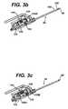
- FIG. 3 ais cross-sectional isometric view of the probe assembly taken along line 3 - 3 in FIG. 2 with the cutter & carriage assembly positioned at the proximal end position;
- FIG. 3 bis cross-sectional isometric view of the probe assembly taken along line 3 - 3 in FIG. 2 with the cutter & carriage assembly positioned between the proximal and distal end positions;
- FIG. 3 cis cross-sectional isometric view of the probe assembly taken along line 3 - 3 in FIG. 2 with the cutter & carriage assembly positioned at the distal end position;
- FIG. 4is an exploded isometric view of the probe assembly of FIG. 2 ;
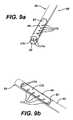
- FIG. 5 ais a schematic diagram of the biopsy needle illustrating the fluid forces and cutter when the cutter is in a proximal end position at the initiation of a cutting cycle;
- FIG. 5 bis a schematic diagram similar to FIG. 5 a , illustrating the cutter and fluid forces as the cutter translates distally to sever a tissue sample;
- FIG. 5 cis a schematic diagram similar to FIG. 5 a , illustrating the fluid forces and cutter when the cutter has closed the aperture and severed the tissue sample;
- FIG. 5 dis a schematic diagram similar to FIG. 5 a , illustrating the fluid forces and cutter as the cutter has reached the distal end position and a tissue sample is aspirated to the tissue storing assembly at the conclusion of a cutting cycle;
- FIG. 6is an isometric view of the rotary drive shaft illustrating a drive coupling configuration
- FIG. 7is an isometric view of an alternative embodiment for the cutter and drive carriage in which the cutter is removable from the probe assembly
- FIG. 8is an isometric view similar to FIG. 7 , illustrating the cutter and rear tube disengaged from the carriage and rotary drive gear for removal from the probe assembly;
- FIG. 9 ais an isometric view of the distal end of the biopsy needle illustrating the needle lumen and divider in greater detail;
- FIG. 9 bis a top isometric view of the distal portion of the biopsy needle illustrating the side tissue receiving port in greater detail;
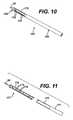
- FIG. 10is an isometric view of an alternative embodiment for the biopsy needle
- FIG. 11is an exploded isometric view of the biopsy needle shown in FIG. 10 ;
- FIG. 12is a more detailed top isometric view of the aperture component shown in FIG. 11 ;
- FIG. 13is a more detailed bottom isometric view of the aperture component shown in FIG. 11 ;
- FIG. 14is an isometric view of a serial tissue stacking assembly
- FIG. 15 ais an isometric view of the probe assembly of FIG. 2 and the distal end of the serial tissue stacking assembly of FIG. 14 , showing connectors for attaching the serial tissue storing assembly to the probe assembly;
- FIG. 15 bis an isometric view similar to FIG. 15 a , illustrating the probe assembly attached to the serial tissue storing assembly;
- FIG. 16is a side cross-sectional view taken along line 16 - 16 of the serial tissue stacking assembly of FIG. 14 ;
- FIG. 17is a side cross-sectional view taken along line 17 - 17 of FIG. 16 , illustrating the vacuum communication holes of the serial tissue stacking tube in greater detail;
- FIG. 18is an isometric view of the translating flexible rod
- FIG. 19is an isometric view showing the reciprocating member and lower connector in greater detail
- FIG. 20is an isometric view showing the probe connectors and distal end of the tissue sample storage tube in greater detail
- FIG. 21is a detailed isometric view of the tissue retrieval mechanism shown in FIG. 14 , with the outer sleeve of the mechanism in a closed position;
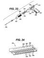
- FIG. 22is a detailed isometric view of the tissue retrieval mechanism of FIG. 21 , showing the outer sleeve of the mechanism in an open position;
- FIG. 23is an exploded isometric view of the mechanism of FIG. 21 ;
- FIG. 24shows a flexible push rod in the form of a plunger for use in removing samples
- FIG. 25is an isometric view showing removal of samples
- FIG. 26 ais a schematic illustration of an embodiment of a separable tissue storage tube
- FIG. 26 bis an isometric sectional view similar to FIG. 26 a , illustrating the vacuum lumen being peeled away from the tissue lumen;
- FIG. 26 cis an isometric view similar to FIG. 26 a , illustrating the tissue lumen removed from the vacuum lumen;
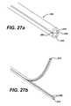
- FIG. 27 ais an isometric sectional view of an alternative embodiment for a separable tissue sample storage tube
- FIG. 27 bis an isometric sectional view similar to FIG. 27 a , illustrating the vacuum lumen being peeled away from the tissue lumen;
- FIG. 28is an isometric sectional view of a third embodiment for a separable tissue storage tube in which the tissue and vacuum lumens are separately extruded and attached together by a mechanical latch;
- FIG. 29is an isometric view of an alternative embodiment for the serial tissue stacking assembly of FIG. 14 , in which the proximal end of the tissue lumen is attached to a tissue stop rather than the tissue retrieval mechanism;
- FIG. 30is an exploded isometric view of the alternative serial tissue stacking assembly embodiment shown in FIG. 29 ;
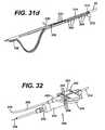
- FIG. 31 ais an isometric sectional view of the alternative serial tissue stacking assembly embodiment shown in FIG. 29 showing the positions of the connectors, sample tube and translating rod of the serial tissue storing assembly when the cutter and drive carriage are advanced distally in an initial cutting cycle;
- FIG. 31 bis an isometric sectional view similar to FIG. 31 a , showing the positions of the connectors, sample tube and translating rod when the cutter and drive carriage are retracted following the initial cutting cycle;
- FIG. 31 cis an isometric sectional view similar to FIG. 31 a , showing the positions of the connectors, sample tube and translating rod of the serial tissue storing assembly when the cutter and drive carriage are advanced distally during a second cutting cycle;
- FIG. 31 dis an isometric sectional view similar to FIG. 31 a , showing the positions of the connectors, sample tube and translating rod of the serial tissue storing assembly when the cutter and drive carriage are retracted following the second cutting cycle;
- FIG. 32is an isometric view of a parallel tissue stacking assembly for the present invention.
- FIG. 33is an exploded isometric view of the parallel tissue stacking assembly of FIG. 32 ;
- FIG. 34is a bottom isometric view of the tissue storage component shown in FIGS. 32 and 33 ;
- FIG. 35is an isometric view of the distal end of the parallel tissue stacking assembly of FIG. 32 , with the tissue storage component removed;
- FIG. 36 ais a more detailed isometric view of the cam member of FIG. 33 , showing the cam member in a retracted position at the beginning of a cutting cycle, with the position of a pair of bosses shown in phantom;
- FIG. 36 bis a more detailed isometric view similar to FIG. 36 a , showing the cam member in an advanced position during the cutting cycle, and a pair of bosses in phantom, with one of the bosses deflecting the camming surface;
- FIG. 36 cis a more detailed isometric view similar to FIG. 36 a , showing the cam member in a retracted position at the conclusion of a cutting cycle, with the position of a boss at the conclusion of the cutting cycle shown in phantom;
- FIG. 37is an exploded isometric view of a cable driven drive assembly for the holster viewed in the proximal direction;
- FIG. 38 ais an isometric view of a probe assembly base unit for use in a mammography guided biopsy procedure
- FIG. 38 bis an isometric view of a probe and probe assembly base unit for use in a mammography guided biopsy procedure
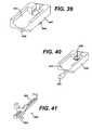
- FIG. 39is an isometric view of a second embodiment of a probe assembly base unit for use in an ultrasound guided biopsy procedure
- FIG. 40is an isometric view of a third embodiment of a probe assembly base unit for use in an MRI guided biopsy procedure.
- FIG. 41is an isometric view of an MRI localization depth gage for interfacing the probe assembly with an MRI unit.
- the present inventionpertains to a biopsy device for obtaining a tissue sample from within a body.
- the biopsy devicecan have a reduced cutting stroke length as compared to device such as commercially available Mammotome brand biopsy devices. Reducing the cutting stroke length decreases the time to acquire each sample, and also the overall size of the biopsy device, thereby enhancing the versatility and ergonomics of the device.
- the reduced stroke length of the cutterenables many of the same probe components to be used in all three primary imaging environments: mammography, ultrasound and MRI.
- the present inventionenables the sequential collection and storage of tissue samples. Tissue samples may be removed from the biopsy device and examined in real-time, as well as sequentially stored for subsequent retrieval at the conclusion of the biopsy procedure. Sequentially storing tissue samples eliminates the need to immediately remove each sample from the device following sampling, thereby further reducing the sample acquisition time.
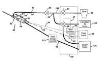
- FIG. 1shows a core sampling biopsy instrument according to the present invention comprising a handpiece identified generally as numeral 30 .
- Handpiece 30can be held comfortably in a single hand, and can be manipulated with a single hand.
- Handpiece 30can include a probe assembly 32 and a detachably connected holster 34 .
- Probe assembly 32can be operatively connected to a vacuum source 36 , such as by a first, lateral tube 40 and a second, axial tube 42 .
- First and second tubes 40 , 42can be made from a flexible, transparent or translucent material, such as silicon tubing, PVC tubing or polyethylene tubing. Using a transparent material enables visualization of the matter flowing through tubes 40 , 42 .
- First tube 40can include a Y connector 44 for connecting to multiple fluid sources.
- a first proximal end of Y connector 44can extend to a first solenoid controlled rotary valve 48 in a control module 46
- the second proximal end of the Y connectorcan extend to a second solenoid controlled rotary valve 51 in control module 46 .
- the first solenoid controlled rotary valve 48 in control module 46can be operable to connect either the vacuum source 36 or the compressed air source 38 to lateral tube 40 .
- compressed airmeans air pressure at or above atmospheric pressure. In one configuration, when valve 48 is activated, vacuum is supplied to tube 40 from vacuum source 36 , and when valve 48 is not activated, pressurized air from compressed air source 38 is supplied through tube 40 .
- the solenoid associated with valve 48can be controlled by a microprocessor 49 in control module 46 , as indicated by dashed line 47 .
- Microprocessor 49can be employed to adjust the position of valve 48 automatically based upon the position of a cutter movably supported within probe assembly 32 .
- the second solenoid controlled rotary valve 51 in control module 46can be employed to either connect a saline supply 50 (such as a saline supply bag, or alternatively, a pressurized reservoir of saline) to a tube 188 or to seal off the proximal end of tube 188 .
- rotary valve 51can be activated by microprocessor 49 to supply saline when a switch on handpiece 30 is actuated.
- first rotary valve 48can be automatically deactivated (such as by microprocessor 49 ) to prevent the interaction of vacuum and saline within lateral tube 40 .
- a stopcock 58may be included in lateral vacuum tube 40 to allow for a syringe injection of saline directly into the tube 40 , if desired.
- a syringe injectioncan be employed to increase the saline pressure in the tube to dislodge any clogs that may occur, such as tissue clogging fluid passageways.
- axial vacuum tube 42can be employed to communicate vacuum from source 36 to probe assembly 32 through a tissue storage assembly 52 .
- Axial tube 42can provide vacuum through the cutter within probe assembly 32 to assist in prolapsing tissue into a side tissue aperture prior to cutting. After cutting occurs, the vacuum in axial line 42 can be employed to help draw a severed tissue sample from probe assembly 32 and into tissue storage assembly 52 , as will be described in further detail below.
- Holster 34can include a control cord 54 for operationally connecting handpiece 30 to control module 46 , and a flexible rotatable shaft 55 connecting the holster to a drive motor 45 .
- a power source 56can be employed to provide energy to control module 46 for powering holster 34 via control cord 54 .
- Switches 60are mounted on holster upper shell 62 to enable an operator to use handpiece 30 with a single hand. One-handed operation allows the operator's other hand to be free, for example, to hold an ultrasonic imaging device.
- Switches 60can include a two-position rocker switch 64 for manually actuating the motion of the cutter (e.g.
- FIG. 2shows probe assembly 32 disconnected from holster 34 .
- Probe assembly 32includes an upper shell 70 and a lower shell 72 , each of which may be injection molded from a rigid, biocompatible plastic, such as a polycarbonate.
- upper and lower shells 70 , 72can be joined together along a joining edge 74 by any of a number of methods well-known for joining plastic parts, including, without limitation, ultrasonic welding, snap fasteners, interference fit, and adhesive joining.
- FIGS. 3 a , 3 b , 3 c , and 4illustrate probe assembly 32 in greater detail.
- FIG. 3 adepicts the cutter assembly and carriage retracted proximally.
- FIG. 3 bdepicts the cutter assembly and carriage partially advanced.
- FIG. 3 cdepicts the cutter assembly and carriage advanced distally.
- the probe assemblycan include a biopsy needle 80 located at a distal end of probe assembly 32 for insertion into a patient's skin to obtain a tissue sample.
- Needle 80comprises an elongated, metallic cannula 82 , which can include an upper lumen, such as an upper cutter lumen 83 for receiving a cutter 100 (as shown in FIG. 5 a ), and a lower lumen, such as a lower lumen 84 for providing a fluid passageway.
- Cutter 100can be disposed within cannula 82 , and can be coaxially disposed within lumen 83 .
- Cannula 82can have any suitable cross-sectional shape, including a circular or oval shaped cross-section. Adjacent and proximal of the distal end of cannula 82 is a side (lateral) tissue receiving port 86 for receiving the tissue to be severed from the patient.
- a sharpened tip of needle 80can be formed by a separate endpiece 90 attached to the distal end of cannula 82 . The sharpened tip of endpiece 90 can be used to pierce the patients skin so that the side tissue receiving port can be positioned in the tissue mass to be sampled.
- Endpiece 90can have a two-sided, flat-shaped point as shown, or any number of other shapes suitable for penetrating the soft tissue of the patient.
- the proximal end of needle 80can be attached to a union sleeve 92 having a longitudinal bore 94 therethrough, and a transverse opening 96 into a widened center portion of the bore.
- the distal end of lateral tube 40can be inserted to fit tightly into transverse opening 96 of union sleeve 92 . This attachment allows the communication of fluids (gas or liquid) between the lower lumen and the lateral tube 40 .
- the cutter 100which can be an elongated, tubular cutter, can be disposed at least partially within upper lumen 83 , and can be supported for translation and rotation within lumen 83 .
- Cutter 100can be supported within needle lumen 84 so as to be translatable in both the distal and proximal directions.
- Cutter 100can have a sharpened distal end 106 for cutting tissue received in upper lumen 83 through side tissue receiving port 86 .
- the cutter 100may be formed of any suitable material, including without limitation a metal, a polymer, a ceramic, or a combination of materials.
- Cutter 100can be translated within lumen 83 by a suitable drive assembly such that distal end 106 travels from a position proximal of the side tissue port 86 (illustrated in FIG. 3 a ) to a position distal of side tissue port 86 (illustrated in FIG. 3 c ), in order to cut tissue received in lumen 83 through the side tissue port 86 .
- a suitable drive assemblysuch that distal end 106 travels from a position proximal of the side tissue port 86 (illustrated in FIG. 3 a ) to a position distal of side tissue port 86 (illustrated in FIG. 3 c ), in order to cut tissue received in lumen 83 through the side tissue port 86 .
- an exterior cuttercan be employed, with the exterior cutter sliding coaxially with an inner cannular needle, and the inner needle can include a side tissue receiving port.
- Union sleeve 92is supported between probe upper and lower shells 70 , 72 to ensure proper alignment between cutter 100 and the union sleeve.
- the cutter 100can be a hollow tube, with a lumen 104 extending axially through the length of cutter 100 .
- the proximal end of cutter 100can extend through an axial bore of a cutter gear 110 .
- Cutter gear 110may be metallic or polymeric, and includes a plurality of cutter gear teeth 112 .
- Cutter gear 110can be driven by a rotary drive shaft 114 having a plurality of drive gear teeth 116 designed to mesh with cutter gear teeth 112 .
- Drive gear teeth 116can extend along the length of drive shaft 114 so as to engage cutter gear teeth 112 as the cutter 100 translates from a proximal most position to a distal most position, as illustrated in FIGS. 5 a - 5 c .
- Drive gear teeth 116can be in continual engagement with cutter gear teeth 112 to rotate cutter 100 whenever drive shaft 114 is rotatably driven.
- Drive shaft 114rotates cutter 100 as the cutter advances distally through tissue receiving port 86 for the cutting of tissue.
- Drive shaft 114may be injection molded from a rigid engineered plastic such as liquid crystal polymer material or, alternatively, could be manufactured from a metallic or non-metallic material.
- Drive shaft 114includes a first axial end 120 extending distally from the shaft.
- Axial end 120is supported for rotation within probe lower shell 72 , such as by a bearing surface feature 122 molded on the inside of the probe shell.
- a second axial end 124extends proximally from rotary drive shaft 114 and is supported in a second bearing surface feature 126 which can also be molded on the inside of probe lower shell 72 .
- An O-ring and bushingmay be provided on each axial end 120 , 124 to provide rotational support and audible noise dampening of the shaft 114 when rotary drive shaft 114 is mounted in probe shell 72 .
- a drive carriage 134is provided in probe assembly 32 to hold cutter gear 110 , and carry the cutter gear and attached cutter 100 during translation in both the distal and proximal directions.
- Drive carriage 134is preferably molded from a rigid polymer and has a cylindrically-shaped bore 136 extending axially therethrough.
- a pair of J-shaped hook extensions 140extend from one side of drive carriage 134 .
- Hook extensions 140rotatably support cutter 100 on either side of cutter gear 110 to provide proximal and distal translation of the cutter gear and cutter during proximal and distal translation of drive carriage 134 .
- Hook extensions 140align cutter 100 and cutter gear 110 in the proper orientation for cutter gear teeth 112 to mesh with drive gear teeth 116 .
- Drive carriage 134is supported on a translation shaft 142 .
- Shaft 142is supported generally parallel to cutter 100 and rotary drive shaft 114 .
- Rotation of the translation shaft 142provides translation of the carriage 134 (and so also cutter gear 110 and cutter 100 ) by employing a lead screw type drive.
- Shaft 142includes an external lead screw thread feature, such as lead screw thread 144 , on its outer surface.
- the screw thread 144extends into a bore 136 in carriage 134 .
- the screw thread 144engages an internal helical threaded surface feature provided on the inner surface of bore 136 . Accordingly, as shaft 142 is rotated, the carriage 134 translates along the threaded feature 144 of the shaft 142 .
- the cutter gear 110 and the cutter 100translate with the carriage 134 . Reversing the direction of rotation of shaft 142 reverses the direction of translation of the carriage 134 and the cutter 100 .
- Translation shaft 142may be injection molded from a rigid engineered plastic such as liquid crystal polymer material or, alternatively, could be manufactured from a metallic or non-metallic material.
- Translation shaft 142 with lead screw thread feature 144can be molded, machined, or otherwise formed.
- carriage 134can be molded or machined to include an internal helical thread in bore 136 . Rotation of shaft 142 drives the carriage and cutter gear 110 and cutter 100 in the distal and proximal directions, depending upon the direction of rotation of shaft 142 , so that cutter 100 translates within probe assembly 32 .
- Cutter gear 110is rigidly attached to cutter 100 so that the cutter translates in the same direction and at the same speed as drive carriage 134 .
- the helical threadis cut short so that the effective pitch width of the thread is zero.
- Biasing memberssuch as compression coil springs 150 A and 150 B ( FIGS. 3 a - c ), are positioned on shaft 142 adjacent the distal and proximal ends of the screw thread 144 . Springs 150 A/B bias carriage 134 back into engagement with lead screw thread 144 when the carriage runs off the thread 144 .
- the zero pitch width ends of lead screw thread 144provide a defined stop for the axial translation of cutter 100 , thereby eliminating the need to slow carriage 134 (i.e. cutter 100 ) as it approaches the distal and proximal ends of the thread.
- This defined stopreduces the required positioning accuracy for carriage 134 relative to shaft 142 , resulting in reduced calibration time at the initialization of a procedure.
- the freewheeling of carriage 134 at the distal and proximal most positions of translation shaft 142eliminates the need to rotate the shaft a precise number of turns during a procedure. Rather, translation shaft 142 only needs to translate at least a minimum number of turns to insure carriage 134 has translated the entire length of lead screw thread 144 and into the zero width thread.
- carriage 134eliminates the need to home the device, allowing probe assembly 32 to be inserted into the patient's tissue without first being attached to holster 34 . After probe assembly 32 is inserted, holster 34 is attached and sampling can be commenced.
- a non-rotating rear tube 152can be provided which tube 152 can extend proximally from the proximal end of cutter 100 just proximal of cutter gear 110 .
- Rear tube 152can be hollow and can have substantially the same inner diameter as cutter 100 , and may be comprised of the same material as the cutter.
- a seal 154can be positioned between cutter 100 and rear tube 152 to enable the cutter to rotate relative to the tube while providing a pneumatic seal between the rear tube 152 and the cutter 100 .
- a rear lumen 156can extend through the length of tube 152 and can be aligned with lumen 104 in cutter 100 . Rear lumen 156 transports excised tissue samples from lumen 104 through probe assembly 32 to the tissue storage assembly 52 .
- Lumen 104 and rear lumen 156are axially aligned to provide a continuous, generally straight line, unobstructed passageway between tissue receiving port 86 and tissue storage assembly 52 for the transport of tissue samples.
- the inner surfaces of cutter 100 and tube 152may be coated with a hydrolubricous material to aid in the proximal transport of the excised tissue samples.
- a lateral extension 158can be provided and can be supported by and extend distally from rear tube 152 for securing the tube to drive carriage 134 .
- the extension 158connects tube 152 to carriage 134 so that tube 152 translates with cutter 100 , and maintains lumens 104 , 156 in continuous fluid-tight communication throughout the cutting cycle.
- FIGS. 5 a - 5 dprovide simplified schematic views of the movement of cutter 100 during a cutting cycle.
- cutter 100initially in the cutting cycle cutter 100 is located at a proximal most position with distal cutting end 106 disposed proximally of the proximal most edge of the side tissue port 86 , and adjacent the proximal end of a lumen divider 170 .
- a lateral vacuum force(indicated by arrow 176 ) can be provided in lower lumen 84 .
- Vacuum force 176can be transmitted from vacuum source 36 through tube 40 to lower lumen 84 through a flow path provided by union sleeve 92 .
- Microprocessor 49can be employed to activate valve 48 to supply vacuum force 176 when switch 64 is actuated by the user to begin moving cutter 100 distally within needle 80 .
- Lateral vacuum force 176communicates with tissue receiving port 86 through fluid passageways 172 disposed under port 86 , and through one or more fluid passageways 174 disposed distally of the port 86 .
- a fluid passageway 174 Ais illustrated disposed distally of port 86 and spaced approximately 180 degrees circumferentially from port 86 .
- a fluid passageway 174 Bis illustrated disposed distally of the port 86 in the distal endpiece 90 of the biopsy probe. Both fluid passageways 174 A and 174 B can provide fluid communication between lower lumen 84 and upper lumen 83 .
- Lateral vacuum force 176can be employed in combination with an axial vacuum force 180 through cutter lumen 104 to draw a tissue sample 182 into tissue port 86 .
- cutter 100can be rotated and simultaneously translated distally to sever the tissue sample from the surrounding tissue. While cutter 100 advances, vacuum forces 176 , 180 can be maintained through lower lumen 84 and cutter lumen 104 to draw the tissue sample into the cutter lumen as the sample is severed. As shown in FIG. 5 b , as cutter 100 advances the cutter slides across fluid passageways 172 , successively blocking the lateral vacuum through the holes.
- cutter 100When cutter 100 reaches the distal most position, as shown in FIG. 5 c , fluid passageways 172 can be completely blocked by the cutter. At this point in the cutting cycle, cutter rotation can be maintained, and the cutter can “freewheel” as described above, with the distal end 106 of the cutter 100 moving proximally and distally in an alternating, oscillating manner. As cutter 100 freewheels, the cutter can oscillate distally and proximally a distance which can be about equal to the pitch of lead screw thread 144 at a frequency corresponding approximately to the rotation speed of translation shaft 142 .
- One or more fluid passageways 174 Acan be positioned in lumen divider 170 such that as cutter 100 is freewheeling at its distal most position, the cutter alternately covers and uncovers (and so opens and closes) the passageways 174 A. With passageway 174 A open, lower lumen 84 remains in fluid communication with cutter lumen 104 through divider 170 despite the blocking of passageways 172 . The repetitive movement of cutter 100 over passageway 174 A can assist in clearing any tissue that may be blocking or clogging passageway 174 A, and to maintain fluid communication through passageway 174 A.
- Fluid Passageway 174 B in distal endpiece 90can be employed in place of or in combination with fluid passageway 174 A. Fluid passageway 174 B can provide fluid communication between lower lumen 84 and upper lumen 83 when passageway 174 is covered by cutter 100 .
- the solenoid on rotary valve 48can be deenergized or otherwise controlled by microprocessor 49 to replace lateral vacuum force 176 with forward pressurized air (either atmospheric or greater) as shown by the arrows in FIG. 5 c .
- the pressurized airis discharged through lateral tube 40 to lumen 84 .
- the pressurized aircommunicates with upper lumen 83 through fluid passageway 174 A (and/or a 174 B) to apply a force against the distal face of sample 182 .
- the force acting on the distal face of sample 182can act in combination with an with axial vacuum force 180 provided through the lumen 104 of cutter 100 .
- the push provided by the force acting on the distal face of the sample 182 in combination with the vacuum “pull” provided by the vacuum provided via the lumen 104 of cutter 100can be employed to move the sample 182 into and through lumen 104 of cutter 100 , as shown in FIG. 5 d .
- a pressurized liquidsuch as saline, can be directed through lower lumen 84 and fluid passageways 174 A and/or 174 B to provide the force on the distal face of sample 182 .
- the cutter 100closes the side tissue port 86 from the flow of fluid (gas or liquid) so that tissue surrounding the outer cannula and side port 86 is not exposed to the fluid.
- the cutter 100can be maintained in a distal most position. Alternatively, the cutter 100 can be retracted back through tissue port 86 towards its initial position in preparation for the next cutting cycle. After cutter 100 is fully retracted, and the tissue sample is translated to tissue storage assembly 52 , lateral vacuum force 176 is again provided via lumen 84 to draw the next tissue sample into port 86 . During the translation of cutter 100 , the cutter can operate in conjunction with divider 170 to separate lumen 83 from lumen 84 .
- cutter 100translates from a point just proximal of side tissue receiving port 86 to a point just distal of the receiving port.
- the severed tissue samplesare directed through the length of the lumen 104 of cutter 100 and out of the proximal end of the cutter 100 , rather than translating the cutter (with the samples carried in the distal end of the cutter) proximally through the needle 80 to eject the samples with a knock-out pin, as in some prior devices. Accordingly, the cutting stroke length can be reduced to be just slightly longer than the length of the side tissue port 86 .
- the distal end of the cutter 100(as well as a length of the cutter 100 ) can remain within needle 80 throughout the cutting cycle, eliminating the need to accommodate the full length of the cutter within the probe housing and proximal of the needle 80 .
- the reduced cutting stroke lengthreduces the required length of translation shaft 142 , since the shaft need only translate the cutter a distance slightly longer than the length of tissue receiving port 86 . Reducing the translation shaft length, and eliminating the need to accommodate the cutter length within the probe housing, enables the length of handpiece 30 to be reduced.
- the time to acquire each tissue sampleis also reduced in the present invention, due to the shortened cutting stroke reducing the time required to advance and retract the cutter through needle 80 .
- lumen divider 170can be formed to extend to the proximal most point of the cutter, rather than through the entire length of the needle. Reducing the length of divider 170 reduces the required materials and cost of manufacturing needle 80 .
- fluid passageways 174 A and/or 174 Bcan also be used to apply saline to the distal face of a severed tissue sample, such as illustrated in FIGS. 5C-D .
- the salinemay be used to provide a push against the tissue sample and thereby aid in moving the tissue sample proximally within the cutter lumen 104 .
- tubing from saline supply bag 50is routed through rotary valve 51 by control module 46 to Y connector 44 and through lateral tube 40 to lumen 84 .
- a buttoncan be provided on handpiece 30 , such that when the button is depressed while the cutter is freewheeling in its distal most position, the valve 51 is activated to connect the saline 50 to lateral tube 40 .
- the saline systemmay be primed by activating the rotary valve 51 to allow the vacuum from vacuum source 36 to draw saline into tubing 188 . Saline will then fill tubing 188 up to Y connector 44 .
- the salinewill flow from Y connector 44 , through lateral tube 40 , and into lumen 84 to be applied against tissue sample 182 .
- tubing 188is sealed off so that the flow of saline to lumen 84 is stopped.
- salinecan be automatically provided to lumen 84 during every cutting cycle.
- a handpiece buttonis not required to operate the saline.
- microprocessor 49automatically activates rotary valve 51 a designated time after cutter 100 reaches the distal most position within needle 80 during the cutting cycle, and deactivates the valve when the cutter has retracted to a designated proximal position.
- a position sensorcan be incorporated with the holster 34 or control module 46 to activate rotary valve 51 based upon the axial position of the cutter in the cutting cycle.
- the position of the cutter 100will automatically activate and deactivate rotary valve 51 , such as when the cutter advances and retracts during each cutting cycle.
- a drive slot 132may be formed in proximal end 124 of shaft 114 for interfacing with a similar-shaped drive slot in a motor drive shaft, or other rotary drive input from holster 34 .
- a star-shaped interface 130may be molded into second axial end 124 of drive shaft 114 .
- Star interface 130can be provided to mate with a similar-shaped male interface which could be provided on the rotary drive shaft of holster 34 to rotate drive shaft 114 .
- the female star interface 130may be molded into the drive shaft from holster 34 and a similar-shaped male interface formed in drive shaft 114 .
- Use of star interface 130or another similar type of interface that is molded into the rotary drive shaft, minimizes the axial length required for the drive coupling. Reducing the drive coupling length reduces the overall length of probe 32 .
- FIGS. 7 and 8illustrate an alternative embodiment for the invention, in which cutter 100 and rear tube 152 are releasable from probe assembly 32 such that the cutter 100 can be repeatedly removed and re-inserted into the probe assembly 32 without disassembling the probe assembly 32 . Removal (either partial or complete removal) of the cutter 100 can be advantageous, such as where the cutter 100 is formed of metal and the imaging device employed with the probe 32 is a Magnetic Resonance Imaging (MRI) device. In FIGS. 7 and 8 , the proximal portion of rear tube 152 is not shown.
- MRIMagnetic Resonance Imaging
- cutter 100 and rear tube 152can be joined at a seal 154 just proximal of cutter gear 110 , such that the cutter is capable of rotating relative to the rear tube 152 (which can be supported to not rotate).
- a cutter release lever 160can be supported on and can protrude from rear tube 152 .
- Release lever 160 as shownincludes an end 162 extending distally towards carriage 134 .
- a lateral slot 164 in end 162is shaped and sized to engage a feature associated with carriage 134 , such as a disk feature 166 which can be securely attached to a proximal hook extension 140 of carriage 134 . While slot 164 engages disk 166 , cutter 100 and rear tube 152 translate together with carriage 134 .
- a spline features 168 located near the proximal end of cutter 100can be employed to engage with a complimenting spline feature on the internal diameter of cutter gear 110 to insure the cutter 100 and cutter gear 110 rotate together.
- the proximal end of release lever 160is squeezed in the direction of tube 152 .
- the squeezing actionunlatches slot 164 from disk 166 , releasing cutter 100 and tube 152 from both the carriage 134 and the cutter gear 110 .
- the tube and cuttermay be pulled proximally through the cutter gear bore and out the proximal end of probe assembly 32 .
- the cutter 100may be repeatedly removed from and reinserted into the probe assembly 32 through an opening in the proximal end of the probe assembly 32 .
- the tissue receiving port 86can be positioned in tissue to be sampled, the cutter 100 can be removed from the probe assembly 32 , the biopsy site can be imaged, such as by using MRI, the cutter can be inserted into the probe assembly 32 , and the tissue received in the side tissue port 86 can be severed with the cutter 100 .
- the step of removing the cutter from the probe assemblycan be performed before or after the tissue port 86 is positioned within the tissue to be sampled. Additionally, the cutter can be removed after a tissue sample is severed, either before or after the needle 80 is removed from tissue.
- a divider 170may be inserted in the distal end of cannula 82 to separate the interior of needle 80 into upper and lower lumens 83 / 84 .
- divider 170extends axially through cannula 82 to a point just proximal of tissue receiving port 86 .
- the proximal end of divider 170can coincide with the proximal most position of cutter 100 so that the cutter and divider combine to separate the upper and lower lumens.
- divider 170could extend axially through the full length of needle 80 . As shown in FIG.
- divider 170can comprise a curved surface that conforms closely to the outer circumference of cutter 100 to enable the cutter to slide along the surface of the divider as the cutter translates within cannula 82 .
- a plurality of fluid passageway holes 172can be formed in divider 170 beneath tissue receiving port 86 (spaced approximately 180 degrees from the port 86 ). Fluid passageways 172 can be sized to permit fluid communication between lumens 83 and 84 (and tissue receiving port 86 ), while preventing excised tissue portions from passing into the lumen.
- Divider 170can also include one or more fluid passageways 174 distal of the tissue receiving port 86 through which compressed gas (e.g. air) or liquid (e.g.
- salinecan be provided to the distal face of a tissue sample located within the cutter lumen 104 while the cutter 100 is in its distal most position closing off the tissue receiving port 86 . With cutter 100 in the distal most position and closing off the tissue receiving port 86 , tissue samples can be pushed through the cutter 100 without exposing tissue surrounding the cannula 82 to the fluid.
- Divider 170may be formed of the same material as cannula 82 , and the longitudinal edge of the divider may be welded or otherwise permanently affixed to the inner diameter of the cannula.
- FIGS. 10 and 11illustrate an alternative embodiment for a biopsy needle suitable for use with a probe assembly 32 .
- the needledesignated by numeral 165
- tube component 168comprises a cannula 171 having a lumen 173 extending there through, and a tissue receiving aperture 175 adjacent the distal end of the tube.
- the aperture component 177comprises an aperture 178 and fluid passageways 179 .
- the tissue piercing component component 90can be insert molded into the aperture component or mechanically secured to it, such as with adhesive or other suitable bonding means.
- aperture component 177can have a semi-tubular shape with an upper opening 178 of substantially the same length as tissue receiving aperture 175 . Opening 178 aligns with tissue receiving aperture 175 when the two components 168 , 177 are assembled together.
- a plurality of fluid passageways 179are formed in a lower surface 169 of aperture component 177 beneath opening 178 . Lower surface 169 can provide a divider for providing a lower lumen when needle 165 is assembled.
- One or more fluid passageways 181can be provided distal of opening 178 so as to be distal of tissue receiving aperture 175 when the needle components are assembled together. Passageways 179 and 181 provide flow communication for compressed fluid (e.g.
- a pair of engagement bosses 183can be provided and can extend from the proximal end of aperture component 177 for attaching the aperture component to tube component 168 .
- aperture component 177is inserted through the distal end of cannula 171 until bosses 183 engage complimentary grooves or holes on the inner diameter of the tube component 168 . The engagement between the bosses and grooves locks aperture component 177 within tube component 168 .
- a circumferential lip 185can be provided on the aperture component 177 .
- the lip 185can provide a seating surface for the distal end of tube component 168 when the aperture component is assembled with the tube component.
- tissue storage assembly 52comprises a serial tissue stacking assembly 190 , such as is shown in FIG. 14 .
- serial tissue stacking assembly 190multiple tissue samples are stacked one behind the next in an end to end configuration, such as in a flexible tube. The samples may be removed individually from the tube and examined in real-time during the procedure or, alternatively, left in the tube until the end of the procedure and removed all at once.
- serial tissue assembly 190can be detachably connected via dual connection mechanisms to probe assembly 32 (so that the serial tissue storage assembly 190 is releasable from the probe assembly), while the proximal end of the assembly 190 can be detachably connected via tube 42 to a vacuum source, such as vacuum source 36 shown in FIG. 1 .
- an upper connector 192 at the distal end of serial tissue assembly 190includes a pair of snap fasteners 194 .
- Fasteners 194engage a pair of fastener engaging features 196 that are disposed at the proximal end of the probe assembly, such as a pair of notches that can be formed in a portion of the proximal end of probe lower shell 72 .
- fasteners 194are engaged with features 196 , as shown in FIG. 15 a , the upper portion of serial tissue assembly 190 is attached to the probe housing.
- a second, lower connector 198can include a similar pair of snap fasteners 200 .
- Lower snap fasteners 200engage a mating pair of features 202 on the proximal end of the rear tube 152 that is shown extending from a proximal opening in probe assembly 32 in FIG. 15 b .
- the distal end of rear tube 152can be joined to carriage 134 as shown in FIG. 8 .
- serial tissue assembly 190When both upper connector 192 and lower connector 198 are attached to probe assembly 32 , the lower portion of serial tissue assembly 190 will translate relative to the fixed upper portion of the assembly during the cutting cycle.
- each of the pairs of snap fasteners 194 , 200are pushed inwardly at the distal ends to disengage the forward tips of the fasteners from the corresponding notches 196 , 202 . After the fasteners are disengaged, serial tissue assembly 190 may be separated from probe assembly 32 .
- serial tissue assembly 190includes a sample storage tube 206 having dual lumens extending axially therethrough.
- the dual lumenscan be generally parallel.
- Tube 206may be comprised of polyvinyl chloride or another similar type of flexible, water insoluble material. Using a clear material for storage tube 206 , such as polyvinyl chloride, enables the stacked tissue samples to be visible from outside the tube.
- Tube 206can include a longitudinally extending center wall divider for separating the two lumens.
- Tube 206can comprise a first lumen, such as stacking lumen 210 , for transferring and storing tissue samples 204 that have been aspirated to the assembly through cutter lumen 104 .
- Tissue stacking lumen 210can be detachably connected to the proximal end of rear tube 152 by lower connector 198 .
- tissue stacking lumen 210can be axially aligned with rear tube lumen 156 to provide a continuous, unobstructed passageway for the movement of tissue samples 204 from tissue receiving port 86 into the tissue lumen stacking lumen 210 .
- tissue samples 204enter tissue stacking lumen 210 , the samples stack serially one behind the next within the lumen, in end to end configuration, as shown in FIG. 16 , so that the order of the samples (the order in which the samples are obtained from the biopsy site) is maintained while the samples are stored in tissue stacking lumen 210 .
- a tissue stopcan be located within the tissue retrieval mechanism 260 at the proximal end of tissue lumen 210 to prevent the first or earliest sample from translating completely through the tissue lumen and into vacuum system 36 .
- the tube 206can comprise a second lumen, tissue stacking vacuum lumen 214 , for providing a flow communication path for vacuum through rear tube 152 and cutter 100 so that severed tissue samples 204 can be drawn through cutter 100 and rear tube 152 into tissue stacking lumen 210 .
- the proximal end of tissue stacking vacuum lumen 214can be detachably connected to vacuum source 36 through a lateral attachment port 216 .
- a plurality of small holes 220can be provided in the center wall divider of tube 206 between lumen 214 and lumen 210 to provide flow communication between the lumens. Holes 220 enable vacuum from source 36 to be communicated from lumen 214 into lumen 210 , to provide vacuum in lumen 104 of cutter 100 . Holes 220 are preferably spaced along the longitudinal axis of tube 206 and separated by a distance in the range of 0.1 to 4 centimeters. Holes 220 may be oriented at an angle relative to the longitudinal axis of tube 206 .
- the angle in holes 220can function as a mechanical diode, in that the edge of the holes 220 opening into lumen 210 can aid in preventing motion of tissue samples in a distal direction, while permitting tissue samples to move proximally in lumen 210 under vacuum force provided by vacuum source 36 . A tissue sample will continue to slide proximally through the lumen 210 until the sample contacts either the tissue stop within the tissue retrieval mechanism 260 or a preceding tissue sample.
- Vacuum holes 220may be formed between lumens 210 , 214 by boring into the upper surface of tube 206 with the sharpened tip of a drill or other appropriate instrument. The tip of the drill bit or other boring instrument can be directed to pass through vacuum lumen 214 to penetrate the center wall of tube 206 that separates the two lumens. As shown in FIG. 14 , an outer sleeve 228 is securely attached to the surface of tube 206 following the formation of vacuum communication holes 220 . Outer sleeve 228 may be attached to tube 206 by an adhesive or other appropriate type of attachment mechanism.
- Outer sleeve 228is attached to sample tube 206 over the openings used to form vacuum communication holes 220 to seal the openings, and prevent vacuum from passing out of vacuum lumen 214 through the openings.
- the distal end of outer sleeve 228can be formed to extend beyond the distal end of vacuum lumen 214 to connect with upper connector 192 .
- Vacuum lumen 214attaches to probe assembly 32 through the connection between outer sleeve 228 and upper connector 192 .
- a translating flexible rod 230is shown disposed at least partially in lumen 214 .
- Rod 230can extend axially through lumen 214 to selectively cover or otherwise block at least some of the vacuum holes 220 .
- Rod 230can then be manipulated, such as by axial movement of rod 230 , to selectively expose vacuum holes 220 in the vacuum lumen.
- rod 230can be advanced distally within vacuum lumen 214 to expose or otherwise unblock/open additional vacuum holes 220 as additional samples are stored in lumen 210 .
- the movement of rod 230maintains a predetermined number of vacuum holes 220 open to provide flow communication between lumens 210 and 214 as additional tissue samples are added to the stack of tissue samples in lumen 210 . This can aid in providing a consistent vacuum force in cutter lumen 104 throughout multiple cutting cycles.
- flexible rod 230can be inserted within lumen 214 such that rod 230 is axially offset within lumen 214 so as to cover or otherwise block most, but not all, of the holes 220 .
- rod 230can be offset distally within vacuum lumen 214 a distance that is slightly longer than the length of tissue receiving port 86 .
- Offsetting rod 230 distally within lumen 210ensures an initial set of holes 220 are exposed to communicate axial vacuum force 180 to tissue receiving port 86 when cutter 100 is in the fully proximal position prior to tissue sampling.
- the axial vacuum force communicated through the exposed holes 220aids in prolapsing tissue into receiving port 86 prior to cutting, as well as pulling the tissue sample proximally into tissue lumen 210 after cutting.
- Rod 230can be selectively moved a predetermined distance distally that is slightly longer than the length of tissue receiving port 86 to expose additional vacuum holes 220 immediately distal of the most recently acquired tissue sample. Rod 230 can be adapted to be automatically advanced distally by the translation of drive carriage 134 within probe assembly 32 , as described further below. The newly exposed vacuum holes 220 continue the communication of vacuum force 180 into tissue lumen 210 for the next cutting cycle.
- Rod 230can be formed of a fluoropolymer resin material such as Teflon® or other suitable flexible material having a low coefficient of friction. Rod 230 can be sized and shaped to conform closely to the inner diameter of vacuum lumen 214 . The close fit between rod 230 and vacuum lumen 214 , as well as the low friction properties of the rod, enable the rod to translate easily within the vacuum lumen without any loss of vacuum force through the distal end of the lumen.
- rod 230extends outside of vacuum lumen 214 through an opening 234 in outer sleeve 228 . As rod 230 is advanced distally, the rod moves further out of vacuum lumen 214 through opening 234 .
- the flexibility of rod 230allows the rod to flex out of opening 234 in outer sleeve 228 as the rod is continually advanced distally, enabling substantially the entire rod to be translated out of vacuum lumen 214 over the course of multiple cutting cycles.
- rod 230can include a plurality of side ratchet teeth 232 spaced longitudinally substantially along the length of the rod. Teeth 232 provide a mechanism to grip and advance rod 230 through vacuum lumen 214 .
- Rod 230can also include a plurality of bottom ratchet teeth 238 .
- Rod 230can be advanced distally within vacuum lumen 214 by the interaction between teeth 232 and a pawl-type latching mechanism 240 on a reciprocating member 242 , which is shown in greater detail in FIG. 19 .
- Reciprocating member 242can be supported on lower connector 198 and reciprocates as cutter 100 is advanced and retracted.
- Reciprocating member 242can have a bifurcated proximal end with proximally extending portions 243 separated by an axially extending slot 244 .
- a ramped surface 246can be formed between portions 243 at a distal end of slot 244 .
- Ramped surface 246can serve to deflect the distal end 231 of rod 230 through opening 234 and alongside the outer surface of tube 206 as the rod is ratcheted out of vacuum lumen 214 .
- Unidirectional engagement pawls 250can be formed to extend from the sides of portions 243 facing slot 244 to engage side ratchet teeth 232 on rod 230 as the rod extends through the groove. The engagement between pawls 250 and ratchet teeth 232 advances rod 230 distally through vacuum lumen 214 .
- reciprocating member 242can be fixed to lower connector 198 for translation along with the lower connector 198 , carriage 134 , and cutter 100 during each cutting cycle.
- drive carriage 134advances distally at the beginning of a cutting cycle to move cutter 100 into receiving port 86
- reciprocating member 242also advances distally.
- pawls 250 in groove 244engage side teeth 232 on rod 230 in lumen 214 to pull the rod distally with the reciprocating member.
- additional vacuum holes 220are exposed.
- reciprocating member 242moves in a proximal direction relative to the fixed vacuum lumen 214 .
- unidirectional bottom ratchet teeth 238located on the bottom side of flexible rod 230 engage vacuum holes 220 within vacuum lumen 214 as shown in FIG. 17 .
- the engagement between the ratchet teeth and holes 220prevents rod 230 from moving proximally within vacuum lumen 214 .
- pawls 250move proximally relative to rod 230
- the pawlsengage the next proximal set of ratchet teeth 232 on rod 230 .
- flexible rod 230could be advanced distally within vacuum lumen 214 as drive carriage 134 is retracted proximally following the cutting of tissue.
- a reversing mechanismsuch as, for example, a cable extending 180° degrees around a pulley, could be utilized so that as the drive carriage retracts the cable pulls the flexible rod distally.
- lower connector 198includes an axially-extending bore 252 for connecting the tissue lumen portion of sample tube 206 to rear tube 152 .
- tissue lumen 210 , bore 252 , and rear tube lumen 156are aligned generally coaxially to provide an unobstructed passageway for the aspiration of tissue samples from cutter 110 and rear tube 152 to lumen 210 .
- FIG. 20illustrates in greater detail connectors 192 , 198 and lumens 210 , 214 .
- vacuum lumen 214can be attached to fixed upper connector 192 by outer sleeve 228 .
- Vacuum lumen 214thus remains fixed in position within serial tissue assembly 190 throughout the cutting cycle.
- Tissue lumen 210extends distally into bore 252 of lower connector 198 . At least a distal portion of tissue lumen 210 will translate along with lower connector 198 and drive carriage 134 during each cutting cycle.
- a distal portion 211 of the sample tube including the distal portion of tissue lumen 210flexes or otherwise deforms downward, enabling the distal end of the tissue lumen to translate along with lower connector 198 and reciprocating member 242 , while vacuum lumen 214 remains fixed in position by outer sleeve 228 .
- tissue retrieval mechanism 260may be located at the proximal end of serial tissue assembly 190 for removing samples from the assembly in real-time following each cutting cycle.
- Tissue retrieval mechanism 260can be is positioned in relation to sample tube 206 just distal of tissue stop 212 ( FIG. 23 ).
- tissue retrieval mechanism 260includes a retractable outer sleeve 262 . Outer sleeve 262 is pneumatically sealed by o-rings 263 to maintain vacuum within sample tube 206 during the cutting cycle.
- outer sleeve 262is manually rotated or translated out of position using pull-tab 270 to expose the tissue sample in tissue lumen 210 .
- a tissue retrieval window 264can be formed in tissue lumen 210 beneath outer sleeve 262 to provide access to the tissue sample in the lumen once the outer sleeve is retracted.
- An air inlet 265can be located distal of tissue retrieval window 264 to apply air pressure to the distal face of the tissue sample 204 in the window, to prevent distal movement of the sample when outer sleeve 262 is retracted due to a pressure imbalance on tissue sample 204 .
- a lower cylinder 266 on retractable sleeve 262can house a return spring 258 for biasing the sleeve into the closed, sealed position. Each end of the spring 258 is secured to the retrieval mechanism 260 with pins 224 .
- the proximal end of tissue retrieval assembly 260can include a vacuum attachment 268 for providing vacuum to tissue lumen 210 , such as from vacuum source 36 . Vacuum attachment port 216 can also be provided to extend through retrieval mechanism 260 to provide vacuum to lumen 214 , such as from vacuum source 36 .
- tissue retrieval assembly 260may be disconnected from sample tube 206 so that tissue samples may be retrieved from the tube, as will be described in further detail below.
- tissue samplesmay be retrieved at the end of a procedure by disconnecting sample tube 206 from probe assembly 32 and removing tissue retrieval assembly 260 from the proximal end of tissue lumen 210 .
- a sample releasing mechanismsuch as, for example, the flexible rod such as plunger-like component 278 shown in FIG. 24 , may be inserted in one end of tissue lumen 210 and advanced there through to extract the samples from the opposite end of the lumen as shown in FIG. 25 .
- the tissue sample tubemay be formed such that vacuum lumen 214 is separable from tissue lumen 210 at the conclusion of the procedure to allow access to the tissue samples stacked within the tissue lumen.
- FIGS. 26 a - 26 cillustrate one embodiment for a separable sample storage tube in which a dual lumen tube 280 is extruded with weakened sides along the exterior of tissue lumen 210 , as indicated by reference numeral 282 , so that a portion of the lumen 210 is separable, such as by peeling, to expose tissue samples.
- the two lumenscan be peeled apart at the weak points 282 , with the upper portion of tissue lumen 210 separating with vacuum lumen 214 as shown in FIG. 26 b .
- the remaining, lower portion of tissue lumen 210will form an open U-channel containing the stacked tissue samples (U-channel shown in FIG. 26 c ).
- the samplesmay be removed from the opened tissue lumen 210 using a forceps or other instrument.
- tissue and vacuum lumens 210 , 214could be extruded separately and assembled together to form a dual lumen tube 284 , an example of which is shown in FIG. 27 a .
- vacuum lumen 214is extruded to include the upper portion of tissue lumen 210 so that tissue lumen 210 forms an open U-channel.
- the tissue and vacuum lumens 210 , 214are joined along the upper edges 286 of the U-channel by an adhesive or other type of fastening mechanism.
- opposite forcesare applied to tube 284 to break the adhesive bond or other fastening means and peel vacuum lumen 214 away from tissue lumen 210 , as shown in FIG. 27 b .
- the samplesmay then be removed from the open tissue lumen.
- a dual lumen tube 290is formed by joining separately extruded vacuum and tissue lumens 210 , 214 .
- vacuum lumen 214is formed as a closed piece having at least one pair of laterally extending teeth 292 .
- Tissue lumen 210is formed as an open U-shaped channel having a corresponding number of pairs of laterally extending notches 294 along the inner surfaces of the channel. Teeth 292 are shaped to engage notches 294 to form a mechanical latch 296 that locks vacuum lumen 214 and tissue lumen 210 together to form the sample tube.
- Mechanical latch 296may be used in combination with an adhesive or other attachment mechanism to lock the vacuum and tissue lumens together.
- FIGS. 29 and 30illustrate an alternative embodiment for serial tissue stacking assembly 190 where sample storage tube 206 is replaced with a separable sample storage tube shown in FIGS. 26-28 .
- the tissue retrieval mechanism 260is replaced with a tissue lumen peel tab 272 .
- a tissue stop featureis located in lumen peel tab 272 at the proximal end of tissue lumen 210 .
- a tubing connector 274connects the proximal end of vacuum lumen 214 to an axial vacuum line, such as a vacuum line 42 communicating with vacuum source 36 .
- tissue samplesare stacked distally from the tissue stop.
- the tissue samples 204can be removed real time by peeling the tissue lumen from the vacuum lumen 214 . Alternately, the tissue samples can be removed at the conclusion of the procedure.
- FIGS. 31 a - 31 dillustrate the advanced and retracted positions of lower connector 198 , tissue lumen 210 and rod 230 for the initial two cutting cycles of a biopsy procedure.
- tissue lumen 210is advanced fully distal as well, with the tissue lumen substantially parallel to outer sleeve 228 .
- tissue lumen 210retracts with drive carriage 134 to a proximal position, as shown in FIG. 31 b .
- tissue lumen 210extends downward, such as by flexing, away from outer sleeve 228 .
- Reciprocating member 242also retracts and grips the next set of ratchet teeth 232 on rod 230 .
- cutter 100is again fully advanced by drive carriage 134 and lower connector 198 again pulls tissue lumen 210 distally.
- engagement pawls 250pull on ratchet teeth 232 of rod 230 to advance the rod through vacuum lumen 214 and out opening 234 .
- tissue lumen 210is again retracted proximally as shown in FIG. 31 d.
- FIG. 32illustrates an alternative embodiment for tissue storage assembly 52 , in which the storage assembly comprises a parallel tissue stacking assembly 300 .
- tissue samplesare stored one beside the next in a tissue storage component and removed at the end of the procedure.
- parallel stacking assembly 300comprises a tissue storage component 302 containing a series of side-by-side lumens 304 .
- Each of the lumens 304is slightly longer than the length of tissue receiving port 86 for storing tissue samples aspirated from the receiving port.
- Component 302may be comprised of a clear plastic material to allow visual inspection of the tissues samples stored therein.
- An integrated knock-out pin 306( FIG.
- each knockout pin 306can include a small central opening large enough to provide flow communication for providing vacuum to lumen 304 , but small enough to not allow a tissue sample to pass out the distal end of lumen 304 .
- a tissue tube 308 having a tissue lumen 310 thereinextends distal of component 302 to connect with tube 152 in probe 32 .
- Tubes 152 and 308can be aligned to provide a continuous, generally straight line passageway from lumen 104 of cutter 100 to a lumen 304 in component 302 .
- An O-ring seal 312shown in FIG. 35 , can be provided at the proximal end of tissue tube 308 to seal the passageway between tissue lumen 310 and the lumen 304 aligned with tube 308 .
- Sample and tissue tubes 152 , 308may be detachably connected by any suitable type of fastening mechanism such as, for example, snap fasteners similar to those shown in FIGS.
- a first vacuum port 314can be located on the proximal side of component 302 to provide vacuum to tissue lumen 310 through the lumen 304 aligned with tube 308 .
- a second lateral vacuum port 316can be employed to provide vacuum to tissue lumen 310 at a position distal of component 302 .
- Each of vacuum ports 314 , 316can be attached to vacuum source 36 through an axial vacuum line 42 to provide vacuum for drawing tissue proximally in lumen 104 of cutter 100 .
- Lateral vacuum port 316can be attached to a vacuum chamber 320 that surrounds tissue tube 308 .
- Tissue tube 308can include a plurality of spaced holes within vacuum chamber 320 for communicating vacuum between the chamber and tube lumen 310 .
- Lateral vacuum port 316 and chamber 320provide additional vacuum for aiding in the proximal movement of a tissue sample (such as in the case where a tissue sample fragments into multiple pieces during sampling).
- component 302can be indexed laterally to axially align the next adjacent lumen with tissue lumen 310 .
- a cam member 322is provided for indexing component 302 .
- Cam member 322is located in a housing 324 that extends beneath component 302 .
- Cam member 322is operatively connected to drive carriage 134 in probe assembly 32 to translate distally and proximally with the drive carriage during each cutting cycle.
- Cam member 322is attached to drive carriage 134 by a mechanical cable 326 that extends distally through an end cap 330 . Cable 326 is attached to drive carriage 134 and pulls cam member 322 distally as the drive carriage 134 moves distally.
- a camming surface 332 on the cam memberinteracts with bosses 334 (shown in FIG. 34 ) on the under surface of component 302 to index component 302 .
- Camming surface 332can comprise an angled, flexible strip of material that is deflected by bosses 334 . As shown in FIG. 36 a , camming surface 332 is in a non-deflected position between two bosses, identified by phantom bosses 336 , 338 , when cam member 322 is in a proximal-most position prior to a cutting cycle.
- camming surface 332is deflected out of position by the contact between boss 336 and a first side of the camming surface.
- boss 336deflects camming surface 332 to a point at which the boss passes through an opening created between the cam surface and a stop block 340 , as shown in FIG. 36 b .
- the camming surfacesprings back into a non-deflected position in contact with stop block 340 .
- a return spring 224 within the distal end of housing 324pushes cam member 322 proximally within the housing.
- the opposite side of camming surface 332contacts boss 336 .
- the angle in camming surface 332causes boss 336 to be pushed laterally, as shown in FIG. 36 c .
- component 302is indexed laterally relative to tissue tube 308 , thereby positioning the next adjacent lumen 304 to receive the next tissue sample through tube 308 .
- component 302is positioned between cam member housing 324 and a detent arm 342 .
- Detent arm 342extends distally across the upper surface of component 302 . As component 302 is indexed laterally by the interaction of camming surface 332 and boss 336 , detent arm 342 engages one of a series of indexing detents 344 . Indexing detents 344 lock the next active lumen 304 into alignment with lumen 310 following each indexing action.
- the plurality of bosses 334 and indexing detents 344enable component 302 to be repetitively indexed to store a plurality of tissue samples during a biopsy procedure. At the conclusion of a biopsy procedure, component 302 may be removed from between housing 324 and detent arm 342 , and the tissue samples removed from the individual tissue lumens 304 .
- the top surface of component 302can include a cover or other removable portion to allow each sample to be easily removed from the lumens 304 .
- FIG. 37is an exploded isometric view of an exemplary drive assembly 350 for holster 34 .
- the translation and rotation drive trains(for providing rotation and translation of cutter 100 ) are driven by a single rotatable cable 55 (also shown in FIG. 1 ) that extends between holster 34 and a remotely located motor, such as a motor in control module 46 .
- a single drive cableis capable of rotating both drive trains due to the reduced cutter stroke of the present invention. The reduced cutter stroke enables the size of handpiece 30 , as well as the load on the drive motor, to be reduced relative to previous biopsy devices.
- Powering handpiece 30 through a single rotatable cableenables the handpiece to be utilized in MRI guided procedures since ferromagnetic motor components are separated from the handpiece.
- the handpiececan also be used in mammography and ultrasound guided procedures. Accordingly, a common probe assembly and handpiece can be utilized for multiple imaging environments. For an MRI guided procedure, the length of the rotatable cable may be increased to accommodate use near or within an MRI bore.
- rotatable cable 55attaches to a drive cable input coupling 352 for providing rotational drive to holster 34 .
- a drive shaft 354 from input coupling 352extends to a proximal housing 356 .
- an input gear 360is mounted on input drive shaft 354 between spacer 362 and bearing 389 so as to engage corresponding gears on a translation drive shaft 364 and a rotation drive shaft 366 .
- the interaction of the input gear 360 with translation shaft gear 370 and rotation shaft gear 372transmits the rotational drive to translation and rotation drive shafts 364 , 366 .
- Translation and rotation drive shafts 364 , 366extend from proximal housing 356 through a pair of bores in a center housing 374 .
- Translation and rotation gears 370 , 372are spaced between the proximal and center housings by bearings 376 .
- holster 34includes a rotary encoder 380 for providing a feedback signal to control module 46 regarding rotation of the drive shafts.
- Encoder 380may be mounted on either the translation or the rotation drive shafts.
- Holster 34also includes an optional planetary gearbox 382 on translation drive shaft 364 .
- Gearbox 382provides a gear reduction between the translation and rotation drive trains to produce differing speeds for the translation of drive carriage 134 and the rotation of cutter 104 .
- drive assembly 350includes a housing 384 .
- Housing 384includes connections for coupling the translation drive train with translation drive input shaft 386 , and the rotational drive train with rotary drive input shaft 388 .
- Each of the drive input shafts 386 , 388has a distal end shaped to operatively engage slots on corresponding drive shafts in probe assembly 32 .
- translation drive input shaft 386is shaped to engage slot 128 of translation shaft 142 (shown in FIG. 4 )
- rotary drive input shaft 388is shaped to engage slot 132 of rotary drive shaft 114 .
- the drive input shaftsmay have molded interfaces, rather than the mating slots and tips shown in FIGS. 4 and 37 , to reduce the coupling length between the shafts.
- Translation and rotary drive shafts 386 , 388extend distally from housing 384 for engagement with drive and translation shafts 114 , 142 when probe assembly 32 and holster 34 are connected.
- the embodiment shown in FIG. 37comprises a single drive cable input for operatively driving the translation and rotation shafts.
- a single motor mounted in the holster 34can replace rotatable cable 55 .
- the single motordrives both the translation and rotation shafts through a suitable gearing assembly.
- the motormay be mounted above or proximal to the drive assembly.
- Another embodimentreplaces the single motor with two motors. One motor would drive the translation drive input shaft and the other would drive the rotary drive input shaft.
- the cutting stroke length for the cutter 100is reduced to slightly longer than the length of tissue receiving port 86 .
- This stroke reductionis possible in part because tissue samples are aspirated through the cutter lumen, rather than being pulled proximally through the needle by a retracting cutter.
- Reducing the cutting stroke lengthhas a number of benefits.
- One of the benefits of a reduced cutting stroke lengthis that the overall size and weight of the probe assembly may be reduced, thereby enabling the biopsy device to be used in imaging environments where size has traditionally been a limitation.
- the reduced size of the probe assemblyenables an essentially common probe assembly to be used in both open and closed bore MRI guided procedures, as well as in mammography and ultrasound procedures, with minor adjustments.
- a common cable driven holstermay also be used in each of the imaging modalities, with the alternative, single or double motor embodiments useable in both the mammography and ultrasound guided procedures.
- a common control modulecan be used to control the handpiece in any of the three imaging environments.
- the probe assemblymay be adapted for use in an MRI guided procedure by utilizing a needle and cutter subassembly that is comprised of a non-ferromagnetic material, such as a plastic or ceramic, in order to reduce image artifacts.
- the cutter assemblymay be removed from the probe, as described above with respect to FIGS. 7 and 8 , for MRI imaging prior to initiation of a cutting cycle. Alternately, the distal end of the cutter may be simply retracted proximally from the tissue receiving port area during imaging.
- Each of the handpiece base unitsmay be used for firing and/or rotating the needle aperture, depending upon the operator's needs and the constrictions of the particular imaging environment.
- Each of the base unitsis designed to accommodate the probe assembly to enable the same probe to be used across imaging modalities.
- FIG. 38 aillustrates a base 420 for use with probe assembly 32 in a mammography guided procedure.
- Base 420may be attached to the stereotactic arm of a mammography machine by a mounting feature 422 .
- a recessed nest area 424is provided in base 420 for accommodating the probe lower shell.
- Probe assembly 32may be lodged in nest 424 prior to the initiation of a procedure.
- a firing button 426is included in base 420 for firing the needle of the probe assembly into the tissue mass of interest.
- a knob 430 on the side of base unit 420compresses a firing spring within the unit. When button 426 is compressed, the spring pushes against probe assembly 32 to forcibly drive the entire probe assembly and nest 424 forward relative to the mounting feature 422 .
- An aperture rotation gear 432is also provided in the recessed area of base 420 for rotating the tissue receiving port of the probe assembly after the needle is positioned within the tissue mass.
- Aperture rotation gear 432includes a plurality of gear teeth 434 .
- Gear teeth 434project partially above the recessed surface area to engage similar shaped teeth on a second gear integral to the needle support component within probe assembly 32 .
- Teeth on the second, needle gearare recessed within the probe shell, but accessible by aperture rotation gear 432 when the probe is lodged in nest 424 .
- a knob 436is provided on the proximal end of base 420 for manually rotating gear 432 . When gear 432 rotates, the engagement between the gears causes the needle to rotate, thereby repositioning the tissue receiving port within the tissue mass.
- Probe assembly 32can include flexible engagement fingers that lock the needle gear and prevent the gear from rotating outside of nest 424 .
- the flexible fingersare deflected so as to disengage from the needle gear, and allow the gear to rotate in response to the rotation of base gear 432 .
- FIG. 38 billustrates the probe assembly 32 lodged in nest 424 .
- FIG. 39illustrates a similar type of probe base unit for use in an ultrasound imaging environment.
- the base unit 440includes a nest 442 for accommodating the lower shell of probe assembly 32 .
- a knob 444is provided for compressing a firing spring within base 440 , as well as a button 446 for releasing the spring to “fire” the probe assembly and nest 424 into a tissue mass.
- base 440may be hand-held and manipulated as required by the operator. Accordingly, a needle rotation mechanism is not necessary for base 440 , since the operator may rotate the needle by manually rotating the base and/or probe assembly.
- a third type of probe base 450is provided for use in MRI guided procedures.
- Base 450may be mounted to a localization unit within the MRI unit.
- the reduced size of the probe assembly in the present inventionreduces the structural requirements for the localization unit due to the reduced cantilever loading generated by the probe.
- MRI base 450includes a recessed nest 452 for accommodating the lower probe shell.
- the baseincludes an aperture rotation gear 454 having a plurality of gear teeth that engage similar shaped teeth that extend from the probe lower shell.
- the gear in the lower probe shellis attached to the needle to rotate the needle whenever gear 454 is rotated, in a manner similar to the mammography nest embodiment shown in FIG. 38 .
- An aperture rotation knob 456is located on the proximal end of base 450 to manually rotate gear 454 and, correspondingly, the tissue receiving aperture in the needle.
- Base 450does not require a firing mechanism for positioning the needle within the tissue.
- multiple needle lengthsmay be used with the probe assembly to enable the probe assembly to more easily fit within the MRI unit. The particular needle length selected will depend upon the depth of the tissue mass of interest within the patient's body.
- an MRI localization depth gage 460may be used for positioning the probe assembly.
- a depth stop 462is attached to the probe assembly and/or the needle 80 .
- the depth stopincludes an adjustment knob 464 for adjusting the desired depth of the probe needle.
Landscapes
- Health & Medical Sciences (AREA)
- Life Sciences & Earth Sciences (AREA)
- Medical Informatics (AREA)
- Engineering & Computer Science (AREA)
- Biomedical Technology (AREA)
- Heart & Thoracic Surgery (AREA)
- Pathology (AREA)
- Molecular Biology (AREA)
- Surgery (AREA)
- Animal Behavior & Ethology (AREA)
- General Health & Medical Sciences (AREA)
- Public Health (AREA)
- Veterinary Medicine (AREA)
- Sampling And Sample Adjustment (AREA)
- Surgical Instruments (AREA)
Abstract
Description
Claims (10)
Priority Applications (9)
| Application Number | Priority Date | Filing Date | Title |
|---|---|---|---|
| US10/953,389US7740594B2 (en) | 2004-09-29 | 2004-09-29 | Cutter for biopsy device |
| AU2005204330AAU2005204330B2 (en) | 2004-09-29 | 2005-08-29 | Cutter for biopsy device |
| CA002521356ACA2521356A1 (en) | 2004-09-29 | 2005-09-27 | Cutter for biopsy device |
| JP2005282483AJP2006095315A (en) | 2004-09-29 | 2005-09-28 | Cutter for biopsy device |
| DE602005004975TDE602005004975T2 (en) | 2004-09-29 | 2005-09-28 | Cutting instrument for biopsy device |
| EP05256055AEP1642535B1 (en) | 2004-09-29 | 2005-09-28 | Cutter for biopsy device |
| BRPI0503976-2ABRPI0503976A (en) | 2004-09-29 | 2005-09-28 | biopsy device cutter |
| CNB200510105601XACN100522073C (en) | 2004-09-29 | 2005-09-28 | Cutter for biopsy device |
| HK06109373.2AHK1088808B (en) | 2004-09-29 | 2006-08-23 | Cutter for biopsy device |
Applications Claiming Priority (1)
| Application Number | Priority Date | Filing Date | Title |
|---|---|---|---|
| US10/953,389US7740594B2 (en) | 2004-09-29 | 2004-09-29 | Cutter for biopsy device |
Publications (2)
| Publication Number | Publication Date |
|---|---|
| US20060074342A1 US20060074342A1 (en) | 2006-04-06 |
| US7740594B2true US7740594B2 (en) | 2010-06-22 |
Family
ID=35427469
Family Applications (1)
| Application Number | Title | Priority Date | Filing Date |
|---|---|---|---|
| US10/953,389Expired - LifetimeUS7740594B2 (en) | 2004-09-29 | 2004-09-29 | Cutter for biopsy device |
Country Status (8)
| Country | Link |
|---|---|
| US (1) | US7740594B2 (en) |
| EP (1) | EP1642535B1 (en) |
| JP (1) | JP2006095315A (en) |
| CN (1) | CN100522073C (en) |
| AU (1) | AU2005204330B2 (en) |
| BR (1) | BRPI0503976A (en) |
| CA (1) | CA2521356A1 (en) |
| DE (1) | DE602005004975T2 (en) |
Cited By (174)
| Publication number | Priority date | Publication date | Assignee | Title |
|---|---|---|---|---|
| US20100222700A1 (en)* | 2004-09-29 | 2010-09-02 | Hibner John A | BIOPSY Device With Sample Storage |
| US20110071433A1 (en)* | 2005-08-05 | 2011-03-24 | Devicor Medical Products, Inc. | Biopsy device with translating valve member |
| US20110105946A1 (en)* | 2009-10-31 | 2011-05-05 | Sorensen Peter L | Biopsy system with infrared communications |
| US8052614B2 (en) | 2002-03-19 | 2011-11-08 | C. R. Bard, Inc. | Biopsy device having a vacuum pump |
| US8157744B2 (en) | 2004-07-09 | 2012-04-17 | Bard Peripheral Vascular, Inc. | Tissue sample flushing system for biopsy device |
| US8162851B2 (en) | 2003-03-29 | 2012-04-24 | C. R. Bard, Inc. | Biopsy needle system having a pressure generating unit |
| US8172773B2 (en) | 2002-03-19 | 2012-05-08 | C. R. Bard, Inc. | Biopsy device and biopsy needle module that can be inserted into the biopsy device |
| US8251917B2 (en) | 2006-08-21 | 2012-08-28 | C. R. Bard, Inc. | Self-contained handheld biopsy needle |
| US8262586B2 (en) | 2006-10-24 | 2012-09-11 | C. R. Bard, Inc. | Large sample low aspect ratio biopsy needle |
| US8267868B2 (en) | 2005-08-10 | 2012-09-18 | C. R. Bard, Inc. | Single-insertion, multiple sample biopsy device with integrated markers |
| US8282574B2 (en) | 2005-08-10 | 2012-10-09 | C. R. Bard, Inc. | Single-insertion, multiple sampling biopsy device usable with various transport systems and integrated markers |
| US8430824B2 (en) | 2009-10-29 | 2013-04-30 | Bard Peripheral Vascular, Inc. | Biopsy driver assembly having a control circuit for conserving battery power |
| US8454532B2 (en) | 2007-12-27 | 2013-06-04 | Devicor Medical Products, Inc. | Clutch and valving system for tetherless biopsy device |
| US8485989B2 (en) | 2009-09-01 | 2013-07-16 | Bard Peripheral Vascular, Inc. | Biopsy apparatus having a tissue sample retrieval mechanism |
| US8485987B2 (en) | 2006-10-06 | 2013-07-16 | Bard Peripheral Vascular, Inc. | Tissue handling system with reduced operator exposure |
| US8597206B2 (en) | 2009-10-12 | 2013-12-03 | Bard Peripheral Vascular, Inc. | Biopsy probe assembly having a mechanism to prevent misalignment of components prior to installation |
| US8597205B2 (en) | 2007-12-20 | 2013-12-03 | C. R. Bard, Inc. | Biopsy device |
| US8690793B2 (en) | 2009-03-16 | 2014-04-08 | C. R. Bard, Inc. | Biopsy device having rotational cutting |
| US8702621B2 (en) | 2005-01-31 | 2014-04-22 | C.R. Bard, Inc. | Quick cycle biopsy system |
| US8702623B2 (en) | 2008-12-18 | 2014-04-22 | Devicor Medical Products, Inc. | Biopsy device with discrete tissue chambers |
| US8708929B2 (en) | 2009-04-15 | 2014-04-29 | Bard Peripheral Vascular, Inc. | Biopsy apparatus having integrated fluid management |
| US8773001B2 (en) | 2009-07-15 | 2014-07-08 | Ethicon Endo-Surgery, Inc. | Rotating transducer mount for ultrasonic surgical instruments |
| US8771200B2 (en) | 2005-08-10 | 2014-07-08 | C.R. Bard, Inc. | Single insertion, multiple sampling biopsy device with linear drive |
| US8779648B2 (en) | 2008-08-06 | 2014-07-15 | Ethicon Endo-Surgery, Inc. | Ultrasonic device for cutting and coagulating with stepped output |
| US8845548B2 (en) | 2009-06-12 | 2014-09-30 | Devicor Medical Products, Inc. | Cutter drive assembly for biopsy device |
| US8905943B2 (en) | 2005-08-05 | 2014-12-09 | Devicor Medical Products, Inc. | Biopsy device with rotatable tissue sample holder |
| US8951272B2 (en) | 2010-02-11 | 2015-02-10 | Ethicon Endo-Surgery, Inc. | Seal arrangements for ultrasonically powered surgical instruments |
| US9066747B2 (en) | 2007-11-30 | 2015-06-30 | Ethicon Endo-Surgery, Inc. | Ultrasonic surgical instrument blades |
| US9095367B2 (en) | 2012-10-22 | 2015-08-04 | Ethicon Endo-Surgery, Inc. | Flexible harmonic waveguides/blades for surgical instruments |
| US9095326B2 (en) | 2006-12-13 | 2015-08-04 | Devicor Medical Products, Inc. | Biopsy system with vacuum control module |
| US9173641B2 (en) | 2009-08-12 | 2015-11-03 | C. R. Bard, Inc. | Biopsy apparatus having integrated thumbwheel mechanism for manual rotation of biopsy cannula |
| US9198714B2 (en) | 2012-06-29 | 2015-12-01 | Ethicon Endo-Surgery, Inc. | Haptic feedback devices for surgical robot |
| US9220527B2 (en) | 2007-07-27 | 2015-12-29 | Ethicon Endo-Surgery, Llc | Surgical instruments |
| US9226767B2 (en) | 2012-06-29 | 2016-01-05 | Ethicon Endo-Surgery, Inc. | Closed feedback control for electrosurgical device |
| US9226766B2 (en) | 2012-04-09 | 2016-01-05 | Ethicon Endo-Surgery, Inc. | Serial communication protocol for medical device |
| US9232979B2 (en) | 2012-02-10 | 2016-01-12 | Ethicon Endo-Surgery, Inc. | Robotically controlled surgical instrument |
| US9237921B2 (en) | 2012-04-09 | 2016-01-19 | Ethicon Endo-Surgery, Inc. | Devices and techniques for cutting and coagulating tissue |
| US9241728B2 (en) | 2013-03-15 | 2016-01-26 | Ethicon Endo-Surgery, Inc. | Surgical instrument with multiple clamping mechanisms |
| US9241731B2 (en) | 2012-04-09 | 2016-01-26 | Ethicon Endo-Surgery, Inc. | Rotatable electrical connection for ultrasonic surgical instruments |
| US9259234B2 (en) | 2010-02-11 | 2016-02-16 | Ethicon Endo-Surgery, Llc | Ultrasonic surgical instruments with rotatable blade and hollow sheath arrangements |
| US9265485B2 (en) | 2004-09-29 | 2016-02-23 | Devicor Medical Products, Inc. | Biopsy device with integral vacuum assist and tissue sample and fluid capturing canister |
| US9283045B2 (en) | 2012-06-29 | 2016-03-15 | Ethicon Endo-Surgery, Llc | Surgical instruments with fluid management system |
| US9326788B2 (en) | 2012-06-29 | 2016-05-03 | Ethicon Endo-Surgery, Llc | Lockout mechanism for use with robotic electrosurgical device |
| US9351754B2 (en) | 2012-06-29 | 2016-05-31 | Ethicon Endo-Surgery, Llc | Ultrasonic surgical instruments with distally positioned jaw assemblies |
| US9393037B2 (en) | 2012-06-29 | 2016-07-19 | Ethicon Endo-Surgery, Llc | Surgical instruments with articulating shafts |
| US9408622B2 (en) | 2012-06-29 | 2016-08-09 | Ethicon Endo-Surgery, Llc | Surgical instruments with articulating shafts |
| US9414853B2 (en) | 2007-07-27 | 2016-08-16 | Ethicon Endo-Surgery, Llc | Ultrasonic end effectors with increased active length |
| US9427249B2 (en) | 2010-02-11 | 2016-08-30 | Ethicon Endo-Surgery, Llc | Rotatable cutting implements with friction reducing material for ultrasonic surgical instruments |
| USRE46135E1 (en) | 2005-08-05 | 2016-09-06 | Devicor Medical Products, Inc. | Vacuum syringe assisted biopsy device |
| US9439669B2 (en) | 2007-07-31 | 2016-09-13 | Ethicon Endo-Surgery, Llc | Ultrasonic surgical instruments |
| US9439668B2 (en) | 2012-04-09 | 2016-09-13 | Ethicon Endo-Surgery, Llc | Switch arrangements for ultrasonic surgical instruments |
| US9445832B2 (en) | 2007-07-31 | 2016-09-20 | Ethicon Endo-Surgery, Llc | Surgical instruments |
| US9498245B2 (en) | 2009-06-24 | 2016-11-22 | Ethicon Endo-Surgery, Llc | Ultrasonic surgical instruments |
| US9504855B2 (en) | 2008-08-06 | 2016-11-29 | Ethicon Surgery, LLC | Devices and techniques for cutting and coagulating tissue |
| US9504483B2 (en) | 2007-03-22 | 2016-11-29 | Ethicon Endo-Surgery, Llc | Surgical instruments |
| US9510850B2 (en) | 2010-02-11 | 2016-12-06 | Ethicon Endo-Surgery, Llc | Ultrasonic surgical instruments |
| US9623237B2 (en) | 2009-10-09 | 2017-04-18 | Ethicon Endo-Surgery, Llc | Surgical generator for ultrasonic and electrosurgical devices |
| US9636135B2 (en) | 2007-07-27 | 2017-05-02 | Ethicon Endo-Surgery, Llc | Ultrasonic surgical instruments |
| US9700339B2 (en) | 2009-05-20 | 2017-07-11 | Ethicon Endo-Surgery, Inc. | Coupling arrangements and methods for attaching tools to ultrasonic surgical instruments |
| US9707027B2 (en) | 2010-05-21 | 2017-07-18 | Ethicon Endo-Surgery, Llc | Medical device |
| US9724118B2 (en) | 2012-04-09 | 2017-08-08 | Ethicon Endo-Surgery, Llc | Techniques for cutting and coagulating tissue for ultrasonic surgical instruments |
| US9724073B2 (en) | 2012-04-16 | 2017-08-08 | Jeff M. Hathaway | Biopsy device |
| US9764164B2 (en) | 2009-07-15 | 2017-09-19 | Ethicon Llc | Ultrasonic surgical instruments |
| US9801648B2 (en) | 2007-03-22 | 2017-10-31 | Ethicon Llc | Surgical instruments |
| US9820768B2 (en) | 2012-06-29 | 2017-11-21 | Ethicon Llc | Ultrasonic surgical instruments with control mechanisms |
| US9848901B2 (en) | 2010-02-11 | 2017-12-26 | Ethicon Llc | Dual purpose surgical instrument for cutting and coagulating tissue |
| US9848902B2 (en) | 2007-10-05 | 2017-12-26 | Ethicon Llc | Ergonomic surgical instruments |
| US9883884B2 (en) | 2007-03-22 | 2018-02-06 | Ethicon Llc | Ultrasonic surgical instruments |
| US9962182B2 (en) | 2010-02-11 | 2018-05-08 | Ethicon Llc | Ultrasonic surgical instruments with moving cutting implement |
| US10010339B2 (en) | 2007-11-30 | 2018-07-03 | Ethicon Llc | Ultrasonic surgical blades |
| US10034684B2 (en) | 2015-06-15 | 2018-07-31 | Ethicon Llc | Apparatus and method for dissecting and coagulating tissue |
| US10034704B2 (en) | 2015-06-30 | 2018-07-31 | Ethicon Llc | Surgical instrument with user adaptable algorithms |
| US10154852B2 (en) | 2015-07-01 | 2018-12-18 | Ethicon Llc | Ultrasonic surgical blade with improved cutting and coagulation features |
| US10179022B2 (en) | 2015-12-30 | 2019-01-15 | Ethicon Llc | Jaw position impedance limiter for electrosurgical instrument |
| US10194973B2 (en) | 2015-09-30 | 2019-02-05 | Ethicon Llc | Generator for digitally generating electrical signal waveforms for electrosurgical and ultrasonic surgical instruments |
| US10201382B2 (en) | 2009-10-09 | 2019-02-12 | Ethicon Llc | Surgical generator for ultrasonic and electrosurgical devices |
| US10201365B2 (en) | 2012-10-22 | 2019-02-12 | Ethicon Llc | Surgeon feedback sensing and display methods |
| US10226273B2 (en) | 2013-03-14 | 2019-03-12 | Ethicon Llc | Mechanical fasteners for use with surgical energy devices |
| US10245064B2 (en) | 2016-07-12 | 2019-04-02 | Ethicon Llc | Ultrasonic surgical instrument with piezoelectric central lumen transducer |
| US10251664B2 (en) | 2016-01-15 | 2019-04-09 | Ethicon Llc | Modular battery powered handheld surgical instrument with multi-function motor via shifting gear assembly |
| US10278721B2 (en) | 2010-07-22 | 2019-05-07 | Ethicon Llc | Electrosurgical instrument with separate closure and cutting members |
| USD847990S1 (en) | 2016-08-16 | 2019-05-07 | Ethicon Llc | Surgical instrument |
| US10285724B2 (en) | 2014-07-31 | 2019-05-14 | Ethicon Llc | Actuation mechanisms and load adjustment assemblies for surgical instruments |
| US10285673B2 (en) | 2013-03-20 | 2019-05-14 | Bard Peripheral Vascular, Inc. | Biopsy device |
| US10285723B2 (en) | 2016-08-09 | 2019-05-14 | Ethicon Llc | Ultrasonic surgical blade with improved heel portion |
| US10321950B2 (en) | 2015-03-17 | 2019-06-18 | Ethicon Llc | Managing tissue treatment |
| US10342602B2 (en) | 2015-03-17 | 2019-07-09 | Ethicon Llc | Managing tissue treatment |
| US10349999B2 (en) | 2014-03-31 | 2019-07-16 | Ethicon Llc | Controlling impedance rise in electrosurgical medical devices |
| US10357303B2 (en) | 2015-06-30 | 2019-07-23 | Ethicon Llc | Translatable outer tube for sealing using shielded lap chole dissector |
| US10376305B2 (en) | 2016-08-05 | 2019-08-13 | Ethicon Llc | Methods and systems for advanced harmonic energy |
| US10420580B2 (en) | 2016-08-25 | 2019-09-24 | Ethicon Llc | Ultrasonic transducer for surgical instrument |
| US10433900B2 (en) | 2011-07-22 | 2019-10-08 | Ethicon Llc | Surgical instruments for tensioning tissue |
| US10441345B2 (en) | 2009-10-09 | 2019-10-15 | Ethicon Llc | Surgical generator for ultrasonic and electrosurgical devices |
| US10456120B2 (en) | 2013-11-05 | 2019-10-29 | C. R. Bard, Inc. | Biopsy device having integrated vacuum |
| US10456193B2 (en) | 2016-05-03 | 2019-10-29 | Ethicon Llc | Medical device with a bilateral jaw configuration for nerve stimulation |
| US10463421B2 (en) | 2014-03-27 | 2019-11-05 | Ethicon Llc | Two stage trigger, clamp and cut bipolar vessel sealer |
| US10463350B2 (en) | 2015-05-01 | 2019-11-05 | C. R. Bard, Inc. | Biopsy device |
| US10485607B2 (en) | 2016-04-29 | 2019-11-26 | Ethicon Llc | Jaw structure with distal closure for electrosurgical instruments |
| US10524854B2 (en) | 2010-07-23 | 2020-01-07 | Ethicon Llc | Surgical instrument |
| US10537352B2 (en) | 2004-10-08 | 2020-01-21 | Ethicon Llc | Tissue pads for use with surgical instruments |
| US10555769B2 (en) | 2016-02-22 | 2020-02-11 | Ethicon Llc | Flexible circuits for electrosurgical instrument |
| US10575892B2 (en) | 2015-12-31 | 2020-03-03 | Ethicon Llc | Adapter for electrical surgical instruments |
| US10595929B2 (en) | 2015-03-24 | 2020-03-24 | Ethicon Llc | Surgical instruments with firing system overload protection mechanisms |
| US10595930B2 (en) | 2015-10-16 | 2020-03-24 | Ethicon Llc | Electrode wiping surgical device |
| US10603064B2 (en) | 2016-11-28 | 2020-03-31 | Ethicon Llc | Ultrasonic transducer |
| US10639092B2 (en) | 2014-12-08 | 2020-05-05 | Ethicon Llc | Electrode configurations for surgical instruments |
| US10646269B2 (en) | 2016-04-29 | 2020-05-12 | Ethicon Llc | Non-linear jaw gap for electrosurgical instruments |
| USRE47996E1 (en) | 2009-10-09 | 2020-05-19 | Ethicon Llc | Surgical generator for ultrasonic and electrosurgical devices |
| US10702329B2 (en) | 2016-04-29 | 2020-07-07 | Ethicon Llc | Jaw structure with distal post for electrosurgical instruments |
| US10716615B2 (en) | 2016-01-15 | 2020-07-21 | Ethicon Llc | Modular battery powered handheld surgical instrument with curved end effectors having asymmetric engagement between jaw and blade |
| US10765470B2 (en) | 2015-06-30 | 2020-09-08 | Ethicon Llc | Surgical system with user adaptable techniques employing simultaneous energy modalities based on tissue parameters |
| US10779879B2 (en) | 2014-03-18 | 2020-09-22 | Ethicon Llc | Detecting short circuits in electrosurgical medical devices |
| US10779845B2 (en) | 2012-06-29 | 2020-09-22 | Ethicon Llc | Ultrasonic surgical instruments with distally positioned transducers |
| US10779848B2 (en) | 2006-01-20 | 2020-09-22 | Ethicon Llc | Ultrasound medical instrument having a medical ultrasonic blade |
| US10820920B2 (en) | 2017-07-05 | 2020-11-03 | Ethicon Llc | Reusable ultrasonic medical devices and methods of their use |
| US10835307B2 (en) | 2001-06-12 | 2020-11-17 | Ethicon Llc | Modular battery powered handheld surgical instrument containing elongated multi-layered shaft |
| US10842522B2 (en) | 2016-07-15 | 2020-11-24 | Ethicon Llc | Ultrasonic surgical instruments having offset blades |
| US10856929B2 (en) | 2014-01-07 | 2020-12-08 | Ethicon Llc | Harvesting energy from a surgical generator |
| US10856896B2 (en) | 2005-10-14 | 2020-12-08 | Ethicon Llc | Ultrasonic device for cutting and coagulating |
| US10874418B2 (en) | 2004-02-27 | 2020-12-29 | Ethicon Llc | Ultrasonic surgical shears and method for sealing a blood vessel using same |
| US10881449B2 (en) | 2012-09-28 | 2021-01-05 | Ethicon Llc | Multi-function bi-polar forceps |
| US10893883B2 (en) | 2016-07-13 | 2021-01-19 | Ethicon Llc | Ultrasonic assembly for use with ultrasonic surgical instruments |
| US10898256B2 (en) | 2015-06-30 | 2021-01-26 | Ethicon Llc | Surgical system with user adaptable techniques based on tissue impedance |
| US10912580B2 (en) | 2013-12-16 | 2021-02-09 | Ethicon Llc | Medical device |
| US10912603B2 (en) | 2013-11-08 | 2021-02-09 | Ethicon Llc | Electrosurgical devices |
| US10925659B2 (en) | 2013-09-13 | 2021-02-23 | Ethicon Llc | Electrosurgical (RF) medical instruments for cutting and coagulating tissue |
| US10952759B2 (en) | 2016-08-25 | 2021-03-23 | Ethicon Llc | Tissue loading of a surgical instrument |
| US10987123B2 (en) | 2012-06-28 | 2021-04-27 | Ethicon Llc | Surgical instruments with articulating shafts |
| US11020140B2 (en) | 2015-06-17 | 2021-06-01 | Cilag Gmbh International | Ultrasonic surgical blade for use with ultrasonic surgical instruments |
| US11033292B2 (en) | 2013-12-16 | 2021-06-15 | Cilag Gmbh International | Medical device |
| US11051873B2 (en) | 2015-06-30 | 2021-07-06 | Cilag Gmbh International | Surgical system with user adaptable techniques employing multiple energy modalities based on tissue parameters |
| US11058447B2 (en) | 2007-07-31 | 2021-07-13 | Cilag Gmbh International | Temperature controlled ultrasonic surgical instruments |
| US11090104B2 (en) | 2009-10-09 | 2021-08-17 | Cilag Gmbh International | Surgical generator for ultrasonic and electrosurgical devices |
| US11116483B2 (en) | 2017-05-19 | 2021-09-14 | Merit Medical Systems, Inc. | Rotating biopsy needle |
| US11129670B2 (en) | 2016-01-15 | 2021-09-28 | Cilag Gmbh International | Modular battery powered handheld surgical instrument with selective application of energy based on button displacement, intensity, or local tissue characterization |
| US11129669B2 (en) | 2015-06-30 | 2021-09-28 | Cilag Gmbh International | Surgical system with user adaptable techniques based on tissue type |
| US11179141B2 (en) | 2006-12-13 | 2021-11-23 | Devicor Medical Products, Inc. | Biopsy system |
| US11229471B2 (en) | 2016-01-15 | 2022-01-25 | Cilag Gmbh International | Modular battery powered handheld surgical instrument with selective application of energy based on tissue characterization |
| US11266430B2 (en) | 2016-11-29 | 2022-03-08 | Cilag Gmbh International | End effector control and calibration |
| US11311326B2 (en) | 2015-02-06 | 2022-04-26 | Cilag Gmbh International | Electrosurgical instrument with rotation and articulation mechanisms |
| US11324527B2 (en) | 2012-11-15 | 2022-05-10 | Cilag Gmbh International | Ultrasonic and electrosurgical devices |
| US11337747B2 (en) | 2014-04-15 | 2022-05-24 | Cilag Gmbh International | Software algorithms for electrosurgical instruments |
| US11399855B2 (en) | 2014-03-27 | 2022-08-02 | Cilag Gmbh International | Electrosurgical devices |
| US11452525B2 (en) | 2019-12-30 | 2022-09-27 | Cilag Gmbh International | Surgical instrument comprising an adjustment system |
| US11589916B2 (en) | 2019-12-30 | 2023-02-28 | Cilag Gmbh International | Electrosurgical instruments with electrodes having variable energy densities |
| US11660089B2 (en) | 2019-12-30 | 2023-05-30 | Cilag Gmbh International | Surgical instrument comprising a sensing system |
| US11684412B2 (en) | 2019-12-30 | 2023-06-27 | Cilag Gmbh International | Surgical instrument with rotatable and articulatable surgical end effector |
| US11696776B2 (en) | 2019-12-30 | 2023-07-11 | Cilag Gmbh International | Articulatable surgical instrument |
| US11723716B2 (en) | 2019-12-30 | 2023-08-15 | Cilag Gmbh International | Electrosurgical instrument with variable control mechanisms |
| US11759251B2 (en) | 2019-12-30 | 2023-09-19 | Cilag Gmbh International | Control program adaptation based on device status and user input |
| US11779387B2 (en) | 2019-12-30 | 2023-10-10 | Cilag Gmbh International | Clamp arm jaw to minimize tissue sticking and improve tissue control |
| US11779329B2 (en) | 2019-12-30 | 2023-10-10 | Cilag Gmbh International | Surgical instrument comprising a flex circuit including a sensor system |
| US11786291B2 (en) | 2019-12-30 | 2023-10-17 | Cilag Gmbh International | Deflectable support of RF energy electrode with respect to opposing ultrasonic blade |
| US11793498B2 (en) | 2017-05-19 | 2023-10-24 | Merit Medical Systems, Inc. | Biopsy needle devices and methods of use |
| US11812957B2 (en) | 2019-12-30 | 2023-11-14 | Cilag Gmbh International | Surgical instrument comprising a signal interference resolution system |
| US11844500B2 (en) | 2017-05-19 | 2023-12-19 | Merit Medical Systems, Inc. | Semi-automatic biopsy needle device and methods of use |
| US11911063B2 (en) | 2019-12-30 | 2024-02-27 | Cilag Gmbh International | Techniques for detecting ultrasonic blade to electrode contact and reducing power to ultrasonic blade |
| US11937866B2 (en) | 2019-12-30 | 2024-03-26 | Cilag Gmbh International | Method for an electrosurgical procedure |
| US11937863B2 (en) | 2019-12-30 | 2024-03-26 | Cilag Gmbh International | Deflectable electrode with variable compression bias along the length of the deflectable electrode |
| US11944366B2 (en) | 2019-12-30 | 2024-04-02 | Cilag Gmbh International | Asymmetric segmented ultrasonic support pad for cooperative engagement with a movable RF electrode |
| US11950797B2 (en) | 2019-12-30 | 2024-04-09 | Cilag Gmbh International | Deflectable electrode with higher distal bias relative to proximal bias |
| US11986201B2 (en) | 2019-12-30 | 2024-05-21 | Cilag Gmbh International | Method for operating a surgical instrument |
| US12023086B2 (en) | 2019-12-30 | 2024-07-02 | Cilag Gmbh International | Electrosurgical instrument for delivering blended energy modalities to tissue |
| US12053224B2 (en) | 2019-12-30 | 2024-08-06 | Cilag Gmbh International | Variation in electrode parameters and deflectable electrode to modify energy density and tissue interaction |
| US12064109B2 (en) | 2019-12-30 | 2024-08-20 | Cilag Gmbh International | Surgical instrument comprising a feedback control circuit |
| US12076006B2 (en) | 2019-12-30 | 2024-09-03 | Cilag Gmbh International | Surgical instrument comprising an orientation detection system |
| US12082808B2 (en) | 2019-12-30 | 2024-09-10 | Cilag Gmbh International | Surgical instrument comprising a control system responsive to software configurations |
| US12114912B2 (en) | 2019-12-30 | 2024-10-15 | Cilag Gmbh International | Non-biased deflectable electrode to minimize contact between ultrasonic blade and electrode |
| US12150627B2 (en) | 2019-12-11 | 2024-11-26 | Merit Medical Systems, Inc. | Bone biopsy device and related methods |
| US12193698B2 (en) | 2016-01-15 | 2025-01-14 | Cilag Gmbh International | Method for self-diagnosing operation of a control switch in a surgical instrument system |
| US12262937B2 (en) | 2019-12-30 | 2025-04-01 | Cilag Gmbh International | User interface for surgical instrument with combination energy modality end-effector |
| US12295556B2 (en) | 2019-09-27 | 2025-05-13 | Merit Medical Systems, Inc. | Rotation biopsy system and handle |
| US12336747B2 (en) | 2019-12-30 | 2025-06-24 | Cilag Gmbh International | Method of operating a combination ultrasonic / bipolar RF surgical device with a combination energy modality end-effector |
| US12343063B2 (en) | 2019-12-30 | 2025-07-01 | Cilag Gmbh International | Multi-layer clamp arm pad for enhanced versatility and performance of a surgical device |
Families Citing this family (15)
| Publication number | Priority date | Publication date | Assignee | Title |
|---|---|---|---|---|
| US7963928B2 (en)* | 2004-06-01 | 2011-06-21 | Krause William R | Automated biopsy and delivery device |
| US20060074344A1 (en)* | 2004-09-29 | 2006-04-06 | Hibner John A | Fluid control for biopsy device |
| US20060184063A1 (en)* | 2005-02-15 | 2006-08-17 | Miller Michael E | Single motor handheld biopsy device |
| US7662109B2 (en)* | 2006-02-01 | 2010-02-16 | Ethicon Endo-Surgery, Inc. | Biopsy device with replaceable probe incorporating static vacuum source dual valve sample stacking retrieval and saline flush |
| US8480595B2 (en)* | 2006-12-13 | 2013-07-09 | Devicor Medical Products, Inc. | Biopsy device with motorized needle cocking |
| EP1932481B1 (en)* | 2006-12-13 | 2010-06-30 | Ethicon Endo-Surgery, Inc. | Biopsy system with vacuum control module |
| US8409235B2 (en)* | 2010-04-30 | 2013-04-02 | Medtronic Xomed, Inc. | Rotary cutting tool with improved cutting and reduced clogging on soft tissue and thin bone |
| US9220485B2 (en) | 2010-08-28 | 2015-12-29 | Endochoice, Inc. | Tissue collection and separation device |
| WO2018235972A1 (en)* | 2017-06-19 | 2018-12-27 | 백운 | A biopsy needle assembly for reducing the starting load of a motor |
| EP4278984A3 (en)* | 2018-07-31 | 2024-01-17 | Devicor Medical Products, Inc. | Core needle biopsy device for collecting multiple samples in a single insertion |
| CN108748707B (en)* | 2018-08-22 | 2023-06-16 | 江西众利超硬材料工具有限公司 | Electrical control system for diamond string bead wire saw |
| CN109330633B (en)* | 2018-11-09 | 2023-10-10 | 上海导向医疗系统有限公司 | Biopsy rotary cutting device |
| CN109330632B (en)* | 2018-11-09 | 2023-09-29 | 上海导向医疗系统有限公司 | Biopsy rotary cutting device |
| US11751960B2 (en)* | 2020-06-18 | 2023-09-12 | Cilag Gmbh International | Robotic surgical tools that translate through instrument driver |
| CN116945283B (en)* | 2023-08-09 | 2025-09-23 | 浙江通达电器有限公司 | Auxiliary device for reciprocating cutting tool and application method thereof |
Citations (16)
| Publication number | Priority date | Publication date | Assignee | Title |
|---|---|---|---|---|
| US3994297A (en) | 1974-12-09 | 1976-11-30 | Kopf J David | Ophthalmic instrument |
| US6042593A (en) | 1995-11-20 | 2000-03-28 | Storz Endoskop Gmbh | Shaving or cutting instrument |
| US6231522B1 (en)* | 2000-02-18 | 2001-05-15 | Ethicon Endo-Surgery, Inc. | Biopsy instrument with breakable sample segments |
| US6273862B1 (en)* | 1998-10-23 | 2001-08-14 | Ethicon Endo-Surgery, Inc | Surgical device for the collection of soft tissue |
| US6428486B2 (en) | 1994-03-24 | 2002-08-06 | Ethicon Endo-Surgery, Inc. | Methods and devices for automated biopsy and collection of soft tissue |
| US6485436B1 (en) | 2000-08-10 | 2002-11-26 | Csaba Truckai | Pressure-assisted biopsy needle apparatus and technique |
| WO2003101306A1 (en) | 2002-05-31 | 2003-12-11 | Vidacare Corporation | Apparatus and method to access the bone marrow |
| EP1410764A1 (en) | 2002-10-18 | 2004-04-21 | Ethicon Endo-Surgery, Inc. | Localization mechanism for an mri compatible biopsy device |
| WO2004075719A2 (en) | 2003-02-24 | 2004-09-10 | Senorx, Inc. | Biopsy device with inner cutting member |
| WO2004075728A2 (en) | 2003-02-25 | 2004-09-10 | Ethicon Endo-Surgery, Inc. | Biopsy device with variable speed cutter advance |
| US20050215921A1 (en)* | 2003-09-30 | 2005-09-29 | John Hibner | Biopsy instrument with internal specimen collection mechanism |
| US20060074345A1 (en) | 2004-09-29 | 2006-04-06 | Hibner John A | Biopsy apparatus and method |
| US20060074344A1 (en) | 2004-09-29 | 2006-04-06 | Hibner John A | Fluid control for biopsy device |
| US20060074343A1 (en) | 2004-09-29 | 2006-04-06 | Hibner John A | Biopsy device with sample storage |
| US20060074346A1 (en) | 2004-09-29 | 2006-04-06 | Hibner John A | Biopsy apparatus and method |
| US7189206B2 (en) | 2003-02-24 | 2007-03-13 | Senorx, Inc. | Biopsy device with inner cutter |
Family Cites Families (8)
| Publication number | Priority date | Publication date | Assignee | Title |
|---|---|---|---|---|
| JP2000007273A (en)* | 1998-06-19 | 2000-01-11 | Tadano Ltd | Safety alarming device for working machine |
| US6602203B2 (en)* | 2000-10-13 | 2003-08-05 | Ethicon Endo-Surgery, Inc. | Remote thumbwheel for a surgical biopsy device |
| US6730044B2 (en)* | 2000-10-13 | 2004-05-04 | Ethicon Endo-Surgery, Inc. | Firing mechanism for use in a surgical biopsy device |
| WO2002069808A2 (en)* | 2000-11-06 | 2002-09-12 | Suros Surgical Systems, Inc. | Biopsy apparatus |
| US7769426B2 (en)* | 2002-04-23 | 2010-08-03 | Ethicon Endo-Surgery, Inc. | Method for using an MRI compatible biopsy device with detachable probe |
| US20030199753A1 (en)* | 2002-04-23 | 2003-10-23 | Ethicon Endo-Surgery | MRI compatible biopsy device with detachable probe |
| US7826883B2 (en)* | 2002-04-23 | 2010-11-02 | Devicor Medical Products, Inc. | Localization mechanism for an MRI compatible biopsy device |
| US7740597B2 (en)* | 2002-12-11 | 2010-06-22 | Ethicon Endo-Surgery, Inc. | Biopsy device with sample tube |
- 2004
- 2004-09-29USUS10/953,389patent/US7740594B2/ennot_activeExpired - Lifetime
- 2005
- 2005-08-29AUAU2005204330Apatent/AU2005204330B2/ennot_activeCeased
- 2005-09-27CACA002521356Apatent/CA2521356A1/ennot_activeAbandoned
- 2005-09-28DEDE602005004975Tpatent/DE602005004975T2/enactiveActive
- 2005-09-28BRBRPI0503976-2Apatent/BRPI0503976A/ennot_activeIP Right Cessation
- 2005-09-28JPJP2005282483Apatent/JP2006095315A/enactivePending
- 2005-09-28EPEP05256055Apatent/EP1642535B1/ennot_activeNot-in-force
- 2005-09-28CNCNB200510105601XApatent/CN100522073C/ennot_activeExpired - Fee Related
Patent Citations (16)
| Publication number | Priority date | Publication date | Assignee | Title |
|---|---|---|---|---|
| US3994297A (en) | 1974-12-09 | 1976-11-30 | Kopf J David | Ophthalmic instrument |
| US6428486B2 (en) | 1994-03-24 | 2002-08-06 | Ethicon Endo-Surgery, Inc. | Methods and devices for automated biopsy and collection of soft tissue |
| US6042593A (en) | 1995-11-20 | 2000-03-28 | Storz Endoskop Gmbh | Shaving or cutting instrument |
| US6273862B1 (en)* | 1998-10-23 | 2001-08-14 | Ethicon Endo-Surgery, Inc | Surgical device for the collection of soft tissue |
| US6231522B1 (en)* | 2000-02-18 | 2001-05-15 | Ethicon Endo-Surgery, Inc. | Biopsy instrument with breakable sample segments |
| US6485436B1 (en) | 2000-08-10 | 2002-11-26 | Csaba Truckai | Pressure-assisted biopsy needle apparatus and technique |
| WO2003101306A1 (en) | 2002-05-31 | 2003-12-11 | Vidacare Corporation | Apparatus and method to access the bone marrow |
| EP1410764A1 (en) | 2002-10-18 | 2004-04-21 | Ethicon Endo-Surgery, Inc. | Localization mechanism for an mri compatible biopsy device |
| WO2004075719A2 (en) | 2003-02-24 | 2004-09-10 | Senorx, Inc. | Biopsy device with inner cutting member |
| US7189206B2 (en) | 2003-02-24 | 2007-03-13 | Senorx, Inc. | Biopsy device with inner cutter |
| WO2004075728A2 (en) | 2003-02-25 | 2004-09-10 | Ethicon Endo-Surgery, Inc. | Biopsy device with variable speed cutter advance |
| US20050215921A1 (en)* | 2003-09-30 | 2005-09-29 | John Hibner | Biopsy instrument with internal specimen collection mechanism |
| US20060074345A1 (en) | 2004-09-29 | 2006-04-06 | Hibner John A | Biopsy apparatus and method |
| US20060074344A1 (en) | 2004-09-29 | 2006-04-06 | Hibner John A | Fluid control for biopsy device |
| US20060074343A1 (en) | 2004-09-29 | 2006-04-06 | Hibner John A | Biopsy device with sample storage |
| US20060074346A1 (en) | 2004-09-29 | 2006-04-06 | Hibner John A | Biopsy apparatus and method |
Non-Patent Citations (1)
| Title |
|---|
| EPO Search Report dated Dec. 2, 2005 for corresponding patent application, European Patent Application No. EP 02 25 6055. |
Cited By (380)
| Publication number | Priority date | Publication date | Assignee | Title |
|---|---|---|---|---|
| US11229472B2 (en) | 2001-06-12 | 2022-01-25 | Cilag Gmbh International | Modular battery powered handheld surgical instrument with multiple magnetic position sensors |
| US10835307B2 (en) | 2001-06-12 | 2020-11-17 | Ethicon Llc | Modular battery powered handheld surgical instrument containing elongated multi-layered shaft |
| US8052614B2 (en) | 2002-03-19 | 2011-11-08 | C. R. Bard, Inc. | Biopsy device having a vacuum pump |
| US10271827B2 (en) | 2002-03-19 | 2019-04-30 | C. R. Bard, Inc. | Disposable biopsy unit |
| US11382608B2 (en) | 2002-03-19 | 2022-07-12 | C. R. Bard, Inc. | Disposable biopsy unit |
| US8109885B2 (en) | 2002-03-19 | 2012-02-07 | C. R. Bard, Inc. | Biopsy device for removing tissue specimens using a vacuum |
| US10335128B2 (en) | 2002-03-19 | 2019-07-02 | C. R. Bard, Inc. | Biopsy device and insertable biopsy needle module |
| US9421002B2 (en) | 2002-03-19 | 2016-08-23 | C. R. Bard, Inc. | Disposable biopsy unit |
| US8172773B2 (en) | 2002-03-19 | 2012-05-08 | C. R. Bard, Inc. | Biopsy device and biopsy needle module that can be inserted into the biopsy device |
| US9439631B2 (en) | 2002-03-19 | 2016-09-13 | C. R. Bard, Inc. | Biopsy device and insertable biopsy needle module |
| US9072502B2 (en) | 2002-03-19 | 2015-07-07 | C. R. Bard, Inc. | Disposable biopsy unit |
| US8951209B2 (en) | 2002-03-19 | 2015-02-10 | C. R. Bard, Inc. | Biopsy device and insertable biopsy needle module |
| US8728004B2 (en) | 2003-03-29 | 2014-05-20 | C.R. Bard, Inc. | Biopsy needle system having a pressure generating unit |
| US8162851B2 (en) | 2003-03-29 | 2012-04-24 | C. R. Bard, Inc. | Biopsy needle system having a pressure generating unit |
| US11730507B2 (en) | 2004-02-27 | 2023-08-22 | Cilag Gmbh International | Ultrasonic surgical shears and method for sealing a blood vessel using same |
| US10874418B2 (en) | 2004-02-27 | 2020-12-29 | Ethicon Llc | Ultrasonic surgical shears and method for sealing a blood vessel using same |
| US8992440B2 (en) | 2004-07-09 | 2015-03-31 | Bard Peripheral Vascular, Inc. | Length detection system for biopsy device |
| US8157744B2 (en) | 2004-07-09 | 2012-04-17 | Bard Peripheral Vascular, Inc. | Tissue sample flushing system for biopsy device |
| US10166011B2 (en) | 2004-07-09 | 2019-01-01 | Bard Peripheral Vascular, Inc. | Transport system for biopsy device |
| US8864680B2 (en) | 2004-07-09 | 2014-10-21 | Bard Peripheral Vascular, Inc. | Transport system for biopsy device |
| US10499888B2 (en) | 2004-07-09 | 2019-12-10 | Bard Peripheral Vascular, Inc. | Tissue sample flushing system for biopsy device |
| US9872672B2 (en) | 2004-07-09 | 2018-01-23 | Bard Peripheral Vascular, Inc. | Length detection system for biopsy device |
| US8366636B2 (en) | 2004-07-09 | 2013-02-05 | Bard Peripheral Vascular, Inc. | Firing system for biopsy device |
| US8926527B2 (en) | 2004-07-09 | 2015-01-06 | Bard Peripheral Vascular, Inc. | Tissue sample flushing system for biopsy device |
| US9456809B2 (en) | 2004-07-09 | 2016-10-04 | Bard Peripheral Vascular, Inc. | Tissue sample flushing system for biopsy device |
| US9345458B2 (en) | 2004-07-09 | 2016-05-24 | Bard Peripheral Vascular, Inc. | Transport system for biopsy device |
| US9468425B2 (en) | 2004-09-29 | 2016-10-18 | Devicor Medical Products, Inc. | Biopsy device with integral vacuum assist and tissue sample and fluid capturing canister |
| US9265485B2 (en) | 2004-09-29 | 2016-02-23 | Devicor Medical Products, Inc. | Biopsy device with integral vacuum assist and tissue sample and fluid capturing canister |
| US9757100B2 (en) | 2004-09-29 | 2017-09-12 | Devicor Medical Products, Inc. | Biopsy device with integral vacuum assist and tissue sample and fluid capturing canister |
| US8491496B2 (en) | 2004-09-29 | 2013-07-23 | Devicor Medical Products, Inc. | Biopsy device with sample storage |
| US20100222700A1 (en)* | 2004-09-29 | 2010-09-02 | Hibner John A | BIOPSY Device With Sample Storage |
| US9901325B2 (en) | 2004-09-29 | 2018-02-27 | Devicor Medical Products, Inc. | Biopsy device with sample storage |
| US11006971B2 (en) | 2004-10-08 | 2021-05-18 | Ethicon Llc | Actuation mechanism for use with an ultrasonic surgical instrument |
| US10537352B2 (en) | 2004-10-08 | 2020-01-21 | Ethicon Llc | Tissue pads for use with surgical instruments |
| US9161743B2 (en) | 2005-01-31 | 2015-10-20 | C. R. Bard, Inc. | Quick cycle biopsy system |
| US11166702B2 (en) | 2005-01-31 | 2021-11-09 | C.R. Bard, Inc. | Quick cycle biopsy system |
| US8702621B2 (en) | 2005-01-31 | 2014-04-22 | C.R. Bard, Inc. | Quick cycle biopsy system |
| US8702622B2 (en) | 2005-01-31 | 2014-04-22 | C.R. Bard, Inc. | Quick cycle biopsy system |
| US10058308B2 (en) | 2005-01-31 | 2018-08-28 | C. R. Bard, Inc. | Method for operating a biopsy apparatus |
| US8568335B2 (en) | 2005-08-05 | 2013-10-29 | Devicor Medical Products, Inc. | Biopsy device with vacuum assisted bleeding control |
| US9968339B2 (en) | 2005-08-05 | 2018-05-15 | Devicor Medical Products, Inc. | Biopsy device with rotatable tissue sample holder |
| US8905943B2 (en) | 2005-08-05 | 2014-12-09 | Devicor Medical Products, Inc. | Biopsy device with rotatable tissue sample holder |
| US8911381B2 (en) | 2005-08-05 | 2014-12-16 | Devicor Medical Products, Inc. | Biopsy device with translating valve member |
| US20110071433A1 (en)* | 2005-08-05 | 2011-03-24 | Devicor Medical Products, Inc. | Biopsy device with translating valve member |
| US9901327B2 (en)* | 2005-08-05 | 2018-02-27 | Devicor Medical Products, Inc. | Biopsy device with translating valve member |
| USRE46135E1 (en) | 2005-08-05 | 2016-09-06 | Devicor Medical Products, Inc. | Vacuum syringe assisted biopsy device |
| US20110144532A1 (en)* | 2005-08-05 | 2011-06-16 | Devicor Medical Products, Inc. | Biopsy device with vacuum assisted bleeding control |
| US8235913B2 (en) | 2005-08-05 | 2012-08-07 | Devicor Medical Products, Inc. | Biopsy device with translating valve member |
| US8979769B2 (en) | 2005-08-05 | 2015-03-17 | Devicor Medical Products, Inc. | Biopsy device with vacuum assisted bleeding control |
| US9907542B2 (en) | 2005-08-05 | 2018-03-06 | Devicor Medical Products, Inc. | Biopsy device with translating valve member |
| US9005136B2 (en) | 2005-08-05 | 2015-04-14 | Devicor Medical Products, Inc. | Biopsy device with vacuum assisted bleeding control |
| US20150141867A1 (en)* | 2005-08-05 | 2015-05-21 | Devicor Medical Products, Inc. | Biopsy device with translating valve member |
| US9414814B2 (en) | 2005-08-05 | 2016-08-16 | Devicor Medical Products, Inc. | Biopsy device with rotatable tissue sample holder |
| US11224412B2 (en) | 2005-08-05 | 2022-01-18 | Devicor Medical Products, Inc. | Biopsy device with translating valve member |
| US8282574B2 (en) | 2005-08-10 | 2012-10-09 | C. R. Bard, Inc. | Single-insertion, multiple sampling biopsy device usable with various transport systems and integrated markers |
| US8771200B2 (en) | 2005-08-10 | 2014-07-08 | C.R. Bard, Inc. | Single insertion, multiple sampling biopsy device with linear drive |
| US10010307B2 (en) | 2005-08-10 | 2018-07-03 | C. R. Bard, Inc. | Single-insertion, multiple sampling biopsy device with linear drive |
| US8721563B2 (en) | 2005-08-10 | 2014-05-13 | C. R. Bard, Inc. | Single-insertion, multiple sample biopsy device with integrated markers |
| US8728003B2 (en) | 2005-08-10 | 2014-05-20 | C.R. Bard Inc. | Single insertion, multiple sample biopsy device with integrated markers |
| US11219431B2 (en) | 2005-08-10 | 2022-01-11 | C.R. Bard, Inc. | Single-insertion, multiple sampling biopsy device with linear drive |
| US11849928B2 (en) | 2005-08-10 | 2023-12-26 | C. R. Bard, Inc. | Single-insertion, multiple sampling biopsy device usable with various transport systems and integrated markers |
| US8961430B2 (en) | 2005-08-10 | 2015-02-24 | C.R. Bard, Inc. | Single-insertion, multiple sampling biopsy device usable with various transport systems and integrated markers |
| US10368849B2 (en) | 2005-08-10 | 2019-08-06 | C. R. Bard, Inc. | Single-insertion, multiple sampling biopsy device usable with various transport systems and integrated markers |
| US8267868B2 (en) | 2005-08-10 | 2012-09-18 | C. R. Bard, Inc. | Single-insertion, multiple sample biopsy device with integrated markers |
| US11998229B2 (en) | 2005-10-14 | 2024-06-04 | Cilag Gmbh International | Ultrasonic device for cutting and coagulating |
| US10856896B2 (en) | 2005-10-14 | 2020-12-08 | Ethicon Llc | Ultrasonic device for cutting and coagulating |
| US12042168B2 (en) | 2006-01-20 | 2024-07-23 | Cilag Gmbh International | Ultrasound medical instrument having a medical ultrasonic blade |
| US10779848B2 (en) | 2006-01-20 | 2020-09-22 | Ethicon Llc | Ultrasound medical instrument having a medical ultrasonic blade |
| US10617399B2 (en) | 2006-08-21 | 2020-04-14 | C.R. Bard, Inc. | Self-contained handheld biopsy needle |
| US8251917B2 (en) | 2006-08-21 | 2012-08-28 | C. R. Bard, Inc. | Self-contained handheld biopsy needle |
| US9439632B2 (en) | 2006-08-21 | 2016-09-13 | C. R. Bard, Inc. | Self-contained handheld biopsy needle |
| US8951208B2 (en) | 2006-08-21 | 2015-02-10 | C. R. Bard, Inc. | Self-contained handheld biopsy needle |
| US9566045B2 (en) | 2006-10-06 | 2017-02-14 | Bard Peripheral Vascular, Inc. | Tissue handling system with reduced operator exposure |
| US11559289B2 (en) | 2006-10-06 | 2023-01-24 | Bard Peripheral Vascular, Inc. | Tissue handling system with reduced operator exposure |
| US10172594B2 (en) | 2006-10-06 | 2019-01-08 | Bard Peripheral Vascular, Inc. | Tissue handling system with reduced operator exposure |
| US8485987B2 (en) | 2006-10-06 | 2013-07-16 | Bard Peripheral Vascular, Inc. | Tissue handling system with reduced operator exposure |
| US10149664B2 (en) | 2006-10-24 | 2018-12-11 | C. R. Bard, Inc. | Large sample low aspect ratio biopsy needle |
| US11583261B2 (en) | 2006-10-24 | 2023-02-21 | C. R. Bard, Inc. | Large sample low aspect ratio biopsy needle |
| US8262586B2 (en) | 2006-10-24 | 2012-09-11 | C. R. Bard, Inc. | Large sample low aspect ratio biopsy needle |
| US11179141B2 (en) | 2006-12-13 | 2021-11-23 | Devicor Medical Products, Inc. | Biopsy system |
| US9095326B2 (en) | 2006-12-13 | 2015-08-04 | Devicor Medical Products, Inc. | Biopsy system with vacuum control module |
| US9504483B2 (en) | 2007-03-22 | 2016-11-29 | Ethicon Endo-Surgery, Llc | Surgical instruments |
| US9987033B2 (en) | 2007-03-22 | 2018-06-05 | Ethicon Llc | Ultrasonic surgical instruments |
| US9883884B2 (en) | 2007-03-22 | 2018-02-06 | Ethicon Llc | Ultrasonic surgical instruments |
| US9801648B2 (en) | 2007-03-22 | 2017-10-31 | Ethicon Llc | Surgical instruments |
| US10828057B2 (en) | 2007-03-22 | 2020-11-10 | Ethicon Llc | Ultrasonic surgical instruments |
| US10722261B2 (en) | 2007-03-22 | 2020-07-28 | Ethicon Llc | Surgical instruments |
| US9913656B2 (en) | 2007-07-27 | 2018-03-13 | Ethicon Llc | Ultrasonic surgical instruments |
| US10398466B2 (en) | 2007-07-27 | 2019-09-03 | Ethicon Llc | Ultrasonic end effectors with increased active length |
| US11607268B2 (en) | 2007-07-27 | 2023-03-21 | Cilag Gmbh International | Surgical instruments |
| US9414853B2 (en) | 2007-07-27 | 2016-08-16 | Ethicon Endo-Surgery, Llc | Ultrasonic end effectors with increased active length |
| US11690641B2 (en) | 2007-07-27 | 2023-07-04 | Cilag Gmbh International | Ultrasonic end effectors with increased active length |
| US9707004B2 (en) | 2007-07-27 | 2017-07-18 | Ethicon Llc | Surgical instruments |
| US9220527B2 (en) | 2007-07-27 | 2015-12-29 | Ethicon Endo-Surgery, Llc | Surgical instruments |
| US9636135B2 (en) | 2007-07-27 | 2017-05-02 | Ethicon Endo-Surgery, Llc | Ultrasonic surgical instruments |
| US9642644B2 (en) | 2007-07-27 | 2017-05-09 | Ethicon Endo-Surgery, Llc | Surgical instruments |
| US10531910B2 (en) | 2007-07-27 | 2020-01-14 | Ethicon Llc | Surgical instruments |
| US12324602B2 (en) | 2007-07-27 | 2025-06-10 | Cilag Gmbh International | Ultrasonic end effectors with increased active length |
| US10420579B2 (en) | 2007-07-31 | 2019-09-24 | Ethicon Llc | Surgical instruments |
| US10426507B2 (en) | 2007-07-31 | 2019-10-01 | Ethicon Llc | Ultrasonic surgical instruments |
| US12220143B2 (en) | 2007-07-31 | 2025-02-11 | Cilag Gmbh International | Temperature controlled ultrasonic surgical instruments |
| US9439669B2 (en) | 2007-07-31 | 2016-09-13 | Ethicon Endo-Surgery, Llc | Ultrasonic surgical instruments |
| US11666784B2 (en) | 2007-07-31 | 2023-06-06 | Cilag Gmbh International | Surgical instruments |
| US11058447B2 (en) | 2007-07-31 | 2021-07-13 | Cilag Gmbh International | Temperature controlled ultrasonic surgical instruments |
| US9445832B2 (en) | 2007-07-31 | 2016-09-20 | Ethicon Endo-Surgery, Llc | Surgical instruments |
| US12268900B2 (en) | 2007-07-31 | 2025-04-08 | Cilag Gmbh International | Surgical instruments |
| US11877734B2 (en) | 2007-07-31 | 2024-01-23 | Cilag Gmbh International | Ultrasonic surgical instruments |
| US9848902B2 (en) | 2007-10-05 | 2017-12-26 | Ethicon Llc | Ergonomic surgical instruments |
| US10828059B2 (en) | 2007-10-05 | 2020-11-10 | Ethicon Llc | Ergonomic surgical instruments |
| US11690643B2 (en) | 2007-11-30 | 2023-07-04 | Cilag Gmbh International | Ultrasonic surgical blades |
| US10888347B2 (en) | 2007-11-30 | 2021-01-12 | Ethicon Llc | Ultrasonic surgical blades |
| US10265094B2 (en) | 2007-11-30 | 2019-04-23 | Ethicon Llc | Ultrasonic surgical blades |
| US9339289B2 (en) | 2007-11-30 | 2016-05-17 | Ehticon Endo-Surgery, LLC | Ultrasonic surgical instrument blades |
| US11439426B2 (en) | 2007-11-30 | 2022-09-13 | Cilag Gmbh International | Ultrasonic surgical blades |
| US10433866B2 (en) | 2007-11-30 | 2019-10-08 | Ethicon Llc | Ultrasonic surgical blades |
| US10045794B2 (en) | 2007-11-30 | 2018-08-14 | Ethicon Llc | Ultrasonic surgical blades |
| US12369939B2 (en) | 2007-11-30 | 2025-07-29 | Cilag Gmbh International | Ultrasonic surgical blades |
| US10245065B2 (en) | 2007-11-30 | 2019-04-02 | Ethicon Llc | Ultrasonic surgical blades |
| US10433865B2 (en) | 2007-11-30 | 2019-10-08 | Ethicon Llc | Ultrasonic surgical blades |
| US12383296B2 (en) | 2007-11-30 | 2025-08-12 | Cilag Gmbh International | Ultrasonic surgical instrument blades |
| US11266433B2 (en) | 2007-11-30 | 2022-03-08 | Cilag Gmbh International | Ultrasonic surgical instrument blades |
| US11253288B2 (en) | 2007-11-30 | 2022-02-22 | Cilag Gmbh International | Ultrasonic surgical instrument blades |
| US9066747B2 (en) | 2007-11-30 | 2015-06-30 | Ethicon Endo-Surgery, Inc. | Ultrasonic surgical instrument blades |
| US10010339B2 (en) | 2007-11-30 | 2018-07-03 | Ethicon Llc | Ultrasonic surgical blades |
| US10441308B2 (en) | 2007-11-30 | 2019-10-15 | Ethicon Llc | Ultrasonic surgical instrument blades |
| US10463887B2 (en) | 2007-11-30 | 2019-11-05 | Ethicon Llc | Ultrasonic surgical blades |
| US11766276B2 (en) | 2007-11-30 | 2023-09-26 | Cilag Gmbh International | Ultrasonic surgical blades |
| US8597205B2 (en) | 2007-12-20 | 2013-12-03 | C. R. Bard, Inc. | Biopsy device |
| US10687791B2 (en) | 2007-12-20 | 2020-06-23 | C. R. Bard, Inc. | Biopsy device |
| US9775588B2 (en) | 2007-12-20 | 2017-10-03 | C. R. Bard, Inc. | Biopsy device |
| US8858463B2 (en) | 2007-12-20 | 2014-10-14 | C. R. Bard, Inc. | Biopsy device |
| US8864682B2 (en) | 2007-12-27 | 2014-10-21 | Devicor Medical Products, Inc. | Clutch and valving system for tetherless biopsy device |
| US8454532B2 (en) | 2007-12-27 | 2013-06-04 | Devicor Medical Products, Inc. | Clutch and valving system for tetherless biopsy device |
| US11890491B2 (en) | 2008-08-06 | 2024-02-06 | Cilag Gmbh International | Devices and techniques for cutting and coagulating tissue |
| US9504855B2 (en) | 2008-08-06 | 2016-11-29 | Ethicon Surgery, LLC | Devices and techniques for cutting and coagulating tissue |
| US10022568B2 (en) | 2008-08-06 | 2018-07-17 | Ethicon Llc | Devices and techniques for cutting and coagulating tissue |
| US8779648B2 (en) | 2008-08-06 | 2014-07-15 | Ethicon Endo-Surgery, Inc. | Ultrasonic device for cutting and coagulating with stepped output |
| US10022567B2 (en) | 2008-08-06 | 2018-07-17 | Ethicon Llc | Devices and techniques for cutting and coagulating tissue |
| US10335614B2 (en) | 2008-08-06 | 2019-07-02 | Ethicon Llc | Devices and techniques for cutting and coagulating tissue |
| US9795808B2 (en) | 2008-08-06 | 2017-10-24 | Ethicon Llc | Devices and techniques for cutting and coagulating tissue |
| US8702623B2 (en) | 2008-12-18 | 2014-04-22 | Devicor Medical Products, Inc. | Biopsy device with discrete tissue chambers |
| US8690793B2 (en) | 2009-03-16 | 2014-04-08 | C. R. Bard, Inc. | Biopsy device having rotational cutting |
| US8708930B2 (en) | 2009-04-15 | 2014-04-29 | Bard Peripheral Vascular, Inc. | Biopsy apparatus having integrated fluid management |
| US8708929B2 (en) | 2009-04-15 | 2014-04-29 | Bard Peripheral Vascular, Inc. | Biopsy apparatus having integrated fluid management |
| US8708928B2 (en) | 2009-04-15 | 2014-04-29 | Bard Peripheral Vascular, Inc. | Biopsy apparatus having integrated fluid management |
| US10709906B2 (en) | 2009-05-20 | 2020-07-14 | Ethicon Llc | Coupling arrangements and methods for attaching tools to ultrasonic surgical instruments |
| US9700339B2 (en) | 2009-05-20 | 2017-07-11 | Ethicon Endo-Surgery, Inc. | Coupling arrangements and methods for attaching tools to ultrasonic surgical instruments |
| US8845548B2 (en) | 2009-06-12 | 2014-09-30 | Devicor Medical Products, Inc. | Cutter drive assembly for biopsy device |
| US9468424B2 (en) | 2009-06-12 | 2016-10-18 | Devicor Medical Products, Inc. | Cutter drive assembly for biopsy device |
| US9498245B2 (en) | 2009-06-24 | 2016-11-22 | Ethicon Endo-Surgery, Llc | Ultrasonic surgical instruments |
| US10688321B2 (en) | 2009-07-15 | 2020-06-23 | Ethicon Llc | Ultrasonic surgical instruments |
| US9764164B2 (en) | 2009-07-15 | 2017-09-19 | Ethicon Llc | Ultrasonic surgical instruments |
| US11717706B2 (en) | 2009-07-15 | 2023-08-08 | Cilag Gmbh International | Ultrasonic surgical instruments |
| US8773001B2 (en) | 2009-07-15 | 2014-07-08 | Ethicon Endo-Surgery, Inc. | Rotating transducer mount for ultrasonic surgical instruments |
| US10575833B2 (en) | 2009-08-12 | 2020-03-03 | C. R. Bard, Inc. | Biopsy apparatus having integrated thumbwheel mechanism for manual rotation of biopsy cannula |
| US9173641B2 (en) | 2009-08-12 | 2015-11-03 | C. R. Bard, Inc. | Biopsy apparatus having integrated thumbwheel mechanism for manual rotation of biopsy cannula |
| US9655599B2 (en) | 2009-08-12 | 2017-05-23 | C. R. Bard, Inc. | Biopsy apparatus having integrated thumbwheel mechanism for manual rotation of biopsy cannula |
| US8485989B2 (en) | 2009-09-01 | 2013-07-16 | Bard Peripheral Vascular, Inc. | Biopsy apparatus having a tissue sample retrieval mechanism |
| US9949726B2 (en) | 2009-09-01 | 2018-04-24 | Bard Peripheral Vscular, Inc. | Biopsy driver assembly having a control circuit for conserving battery power |
| US9623237B2 (en) | 2009-10-09 | 2017-04-18 | Ethicon Endo-Surgery, Llc | Surgical generator for ultrasonic and electrosurgical devices |
| US12408967B2 (en) | 2009-10-09 | 2025-09-09 | Cilag Gmbh International | Surgical generator for ultrasonic and electrosurgical devices |
| US10441345B2 (en) | 2009-10-09 | 2019-10-15 | Ethicon Llc | Surgical generator for ultrasonic and electrosurgical devices |
| US10265117B2 (en) | 2009-10-09 | 2019-04-23 | Ethicon Llc | Surgical generator method for controlling and ultrasonic transducer waveform for ultrasonic and electrosurgical devices |
| US10201382B2 (en) | 2009-10-09 | 2019-02-12 | Ethicon Llc | Surgical generator for ultrasonic and electrosurgical devices |
| US11090104B2 (en) | 2009-10-09 | 2021-08-17 | Cilag Gmbh International | Surgical generator for ultrasonic and electrosurgical devices |
| US11871982B2 (en) | 2009-10-09 | 2024-01-16 | Cilag Gmbh International | Surgical generator for ultrasonic and electrosurgical devices |
| US10263171B2 (en) | 2009-10-09 | 2019-04-16 | Ethicon Llc | Surgical generator for ultrasonic and electrosurgical devices |
| USRE47996E1 (en) | 2009-10-09 | 2020-05-19 | Ethicon Llc | Surgical generator for ultrasonic and electrosurgical devices |
| US8597206B2 (en) | 2009-10-12 | 2013-12-03 | Bard Peripheral Vascular, Inc. | Biopsy probe assembly having a mechanism to prevent misalignment of components prior to installation |
| US8430824B2 (en) | 2009-10-29 | 2013-04-30 | Bard Peripheral Vascular, Inc. | Biopsy driver assembly having a control circuit for conserving battery power |
| US8808197B2 (en) | 2009-10-29 | 2014-08-19 | Bard Peripheral Vascular, Inc. | Biopsy driver assembly having a control circuit for conserving battery power |
| US20110105946A1 (en)* | 2009-10-31 | 2011-05-05 | Sorensen Peter L | Biopsy system with infrared communications |
| US10299810B2 (en) | 2010-02-11 | 2019-05-28 | Ethicon Llc | Rotatable cutting implements with friction reducing material for ultrasonic surgical instruments |
| US9259234B2 (en) | 2010-02-11 | 2016-02-16 | Ethicon Endo-Surgery, Llc | Ultrasonic surgical instruments with rotatable blade and hollow sheath arrangements |
| US9649126B2 (en) | 2010-02-11 | 2017-05-16 | Ethicon Endo-Surgery, Llc | Seal arrangements for ultrasonically powered surgical instruments |
| US20180199957A1 (en)* | 2010-02-11 | 2018-07-19 | Ethicon Llc | Dual purpose surgical instrument for cutting and coagulating tissue |
| US9510850B2 (en) | 2010-02-11 | 2016-12-06 | Ethicon Endo-Surgery, Llc | Ultrasonic surgical instruments |
| US9848901B2 (en) | 2010-02-11 | 2017-12-26 | Ethicon Llc | Dual purpose surgical instrument for cutting and coagulating tissue |
| US11382642B2 (en) | 2010-02-11 | 2022-07-12 | Cilag Gmbh International | Rotatable cutting implements with friction reducing material for ultrasonic surgical instruments |
| US9427249B2 (en) | 2010-02-11 | 2016-08-30 | Ethicon Endo-Surgery, Llc | Rotatable cutting implements with friction reducing material for ultrasonic surgical instruments |
| US11369402B2 (en) | 2010-02-11 | 2022-06-28 | Cilag Gmbh International | Control systems for ultrasonically powered surgical instruments |
| US9962182B2 (en) | 2010-02-11 | 2018-05-08 | Ethicon Llc | Ultrasonic surgical instruments with moving cutting implement |
| US8951272B2 (en) | 2010-02-11 | 2015-02-10 | Ethicon Endo-Surgery, Inc. | Seal arrangements for ultrasonically powered surgical instruments |
| US10117667B2 (en) | 2010-02-11 | 2018-11-06 | Ethicon Llc | Control systems for ultrasonically powered surgical instruments |
| US10835768B2 (en)* | 2010-02-11 | 2020-11-17 | Ethicon Llc | Dual purpose surgical instrument for cutting and coagulating tissue |
| US9707027B2 (en) | 2010-05-21 | 2017-07-18 | Ethicon Endo-Surgery, Llc | Medical device |
| US10278721B2 (en) | 2010-07-22 | 2019-05-07 | Ethicon Llc | Electrosurgical instrument with separate closure and cutting members |
| US10524854B2 (en) | 2010-07-23 | 2020-01-07 | Ethicon Llc | Surgical instrument |
| US10433900B2 (en) | 2011-07-22 | 2019-10-08 | Ethicon Llc | Surgical instruments for tensioning tissue |
| US9232979B2 (en) | 2012-02-10 | 2016-01-12 | Ethicon Endo-Surgery, Inc. | Robotically controlled surgical instrument |
| US9925003B2 (en) | 2012-02-10 | 2018-03-27 | Ethicon Endo-Surgery, Llc | Robotically controlled surgical instrument |
| US10729494B2 (en) | 2012-02-10 | 2020-08-04 | Ethicon Llc | Robotically controlled surgical instrument |
| US9237921B2 (en) | 2012-04-09 | 2016-01-19 | Ethicon Endo-Surgery, Inc. | Devices and techniques for cutting and coagulating tissue |
| US9724118B2 (en) | 2012-04-09 | 2017-08-08 | Ethicon Endo-Surgery, Llc | Techniques for cutting and coagulating tissue for ultrasonic surgical instruments |
| US9700343B2 (en) | 2012-04-09 | 2017-07-11 | Ethicon Endo-Surgery, Llc | Devices and techniques for cutting and coagulating tissue |
| US11419626B2 (en) | 2012-04-09 | 2022-08-23 | Cilag Gmbh International | Switch arrangements for ultrasonic surgical instruments |
| US9439668B2 (en) | 2012-04-09 | 2016-09-13 | Ethicon Endo-Surgery, Llc | Switch arrangements for ultrasonic surgical instruments |
| US9226766B2 (en) | 2012-04-09 | 2016-01-05 | Ethicon Endo-Surgery, Inc. | Serial communication protocol for medical device |
| US10517627B2 (en) | 2012-04-09 | 2019-12-31 | Ethicon Llc | Switch arrangements for ultrasonic surgical instruments |
| US9241731B2 (en) | 2012-04-09 | 2016-01-26 | Ethicon Endo-Surgery, Inc. | Rotatable electrical connection for ultrasonic surgical instruments |
| US12167866B2 (en) | 2012-04-09 | 2024-12-17 | Cilag Gmbh International | Switch arrangements for ultrasonic surgical instruments |
| US9724073B2 (en) | 2012-04-16 | 2017-08-08 | Jeff M. Hathaway | Biopsy device |
| US10987123B2 (en) | 2012-06-28 | 2021-04-27 | Ethicon Llc | Surgical instruments with articulating shafts |
| US11602371B2 (en) | 2012-06-29 | 2023-03-14 | Cilag Gmbh International | Ultrasonic surgical instruments with control mechanisms |
| US9198714B2 (en) | 2012-06-29 | 2015-12-01 | Ethicon Endo-Surgery, Inc. | Haptic feedback devices for surgical robot |
| US11426191B2 (en) | 2012-06-29 | 2022-08-30 | Cilag Gmbh International | Ultrasonic surgical instruments with distally positioned jaw assemblies |
| US10441310B2 (en) | 2012-06-29 | 2019-10-15 | Ethicon Llc | Surgical instruments with curved section |
| US10524872B2 (en) | 2012-06-29 | 2020-01-07 | Ethicon Llc | Closed feedback control for electrosurgical device |
| US11583306B2 (en) | 2012-06-29 | 2023-02-21 | Cilag Gmbh International | Surgical instruments with articulating shafts |
| US9820768B2 (en) | 2012-06-29 | 2017-11-21 | Ethicon Llc | Ultrasonic surgical instruments with control mechanisms |
| US12268408B2 (en) | 2012-06-29 | 2025-04-08 | Cilag Gmbh International | Haptic feedback devices for surgical robot |
| US10398497B2 (en) | 2012-06-29 | 2019-09-03 | Ethicon Llc | Lockout mechanism for use with robotic electrosurgical device |
| US9737326B2 (en) | 2012-06-29 | 2017-08-22 | Ethicon Endo-Surgery, Llc | Haptic feedback devices for surgical robot |
| US11096752B2 (en) | 2012-06-29 | 2021-08-24 | Cilag Gmbh International | Closed feedback control for electrosurgical device |
| US9713507B2 (en) | 2012-06-29 | 2017-07-25 | Ethicon Endo-Surgery, Llc | Closed feedback control for electrosurgical device |
| US11717311B2 (en) | 2012-06-29 | 2023-08-08 | Cilag Gmbh International | Surgical instruments with articulating shafts |
| US10842580B2 (en) | 2012-06-29 | 2020-11-24 | Ethicon Llc | Ultrasonic surgical instruments with control mechanisms |
| US10993763B2 (en) | 2012-06-29 | 2021-05-04 | Ethicon Llc | Lockout mechanism for use with robotic electrosurgical device |
| US10543008B2 (en) | 2012-06-29 | 2020-01-28 | Ethicon Llc | Ultrasonic surgical instruments with distally positioned jaw assemblies |
| US10966747B2 (en) | 2012-06-29 | 2021-04-06 | Ethicon Llc | Haptic feedback devices for surgical robot |
| US9226767B2 (en) | 2012-06-29 | 2016-01-05 | Ethicon Endo-Surgery, Inc. | Closed feedback control for electrosurgical device |
| US10779845B2 (en) | 2012-06-29 | 2020-09-22 | Ethicon Llc | Ultrasonic surgical instruments with distally positioned transducers |
| US9283045B2 (en) | 2012-06-29 | 2016-03-15 | Ethicon Endo-Surgery, Llc | Surgical instruments with fluid management system |
| US9408622B2 (en) | 2012-06-29 | 2016-08-09 | Ethicon Endo-Surgery, Llc | Surgical instruments with articulating shafts |
| US9326788B2 (en) | 2012-06-29 | 2016-05-03 | Ethicon Endo-Surgery, Llc | Lockout mechanism for use with robotic electrosurgical device |
| US11871955B2 (en) | 2012-06-29 | 2024-01-16 | Cilag Gmbh International | Surgical instruments with articulating shafts |
| US9393037B2 (en) | 2012-06-29 | 2016-07-19 | Ethicon Endo-Surgery, Llc | Surgical instruments with articulating shafts |
| US9351754B2 (en) | 2012-06-29 | 2016-05-31 | Ethicon Endo-Surgery, Llc | Ultrasonic surgical instruments with distally positioned jaw assemblies |
| US10335182B2 (en) | 2012-06-29 | 2019-07-02 | Ethicon Llc | Surgical instruments with articulating shafts |
| US10335183B2 (en) | 2012-06-29 | 2019-07-02 | Ethicon Llc | Feedback devices for surgical control systems |
| US10881449B2 (en) | 2012-09-28 | 2021-01-05 | Ethicon Llc | Multi-function bi-polar forceps |
| US11179173B2 (en) | 2012-10-22 | 2021-11-23 | Cilag Gmbh International | Surgical instrument |
| US9095367B2 (en) | 2012-10-22 | 2015-08-04 | Ethicon Endo-Surgery, Inc. | Flexible harmonic waveguides/blades for surgical instruments |
| US10201365B2 (en) | 2012-10-22 | 2019-02-12 | Ethicon Llc | Surgeon feedback sensing and display methods |
| US9795405B2 (en) | 2012-10-22 | 2017-10-24 | Ethicon Llc | Surgical instrument |
| US11324527B2 (en) | 2012-11-15 | 2022-05-10 | Cilag Gmbh International | Ultrasonic and electrosurgical devices |
| US10226273B2 (en) | 2013-03-14 | 2019-03-12 | Ethicon Llc | Mechanical fasteners for use with surgical energy devices |
| US11272952B2 (en) | 2013-03-14 | 2022-03-15 | Cilag Gmbh International | Mechanical fasteners for use with surgical energy devices |
| US9743947B2 (en) | 2013-03-15 | 2017-08-29 | Ethicon Endo-Surgery, Llc | End effector with a clamp arm assembly and blade |
| US9241728B2 (en) | 2013-03-15 | 2016-01-26 | Ethicon Endo-Surgery, Inc. | Surgical instrument with multiple clamping mechanisms |
| US10285673B2 (en) | 2013-03-20 | 2019-05-14 | Bard Peripheral Vascular, Inc. | Biopsy device |
| US11779316B2 (en) | 2013-03-20 | 2023-10-10 | Bard Peripheral Vascular, Inc. | Biopsy device |
| US10925659B2 (en) | 2013-09-13 | 2021-02-23 | Ethicon Llc | Electrosurgical (RF) medical instruments for cutting and coagulating tissue |
| US10456120B2 (en) | 2013-11-05 | 2019-10-29 | C. R. Bard, Inc. | Biopsy device having integrated vacuum |
| US11534148B2 (en) | 2013-11-05 | 2022-12-27 | C. R. Bard, Inc. | Biopsy device having integrated vacuum |
| US10912603B2 (en) | 2013-11-08 | 2021-02-09 | Ethicon Llc | Electrosurgical devices |
| US11033292B2 (en) | 2013-12-16 | 2021-06-15 | Cilag Gmbh International | Medical device |
| US10912580B2 (en) | 2013-12-16 | 2021-02-09 | Ethicon Llc | Medical device |
| US10856929B2 (en) | 2014-01-07 | 2020-12-08 | Ethicon Llc | Harvesting energy from a surgical generator |
| US10932847B2 (en) | 2014-03-18 | 2021-03-02 | Ethicon Llc | Detecting short circuits in electrosurgical medical devices |
| US10779879B2 (en) | 2014-03-18 | 2020-09-22 | Ethicon Llc | Detecting short circuits in electrosurgical medical devices |
| US10463421B2 (en) | 2014-03-27 | 2019-11-05 | Ethicon Llc | Two stage trigger, clamp and cut bipolar vessel sealer |
| US11399855B2 (en) | 2014-03-27 | 2022-08-02 | Cilag Gmbh International | Electrosurgical devices |
| US10349999B2 (en) | 2014-03-31 | 2019-07-16 | Ethicon Llc | Controlling impedance rise in electrosurgical medical devices |
| US11471209B2 (en) | 2014-03-31 | 2022-10-18 | Cilag Gmbh International | Controlling impedance rise in electrosurgical medical devices |
| US11337747B2 (en) | 2014-04-15 | 2022-05-24 | Cilag Gmbh International | Software algorithms for electrosurgical instruments |
| US11413060B2 (en) | 2014-07-31 | 2022-08-16 | Cilag Gmbh International | Actuation mechanisms and load adjustment assemblies for surgical instruments |
| US10285724B2 (en) | 2014-07-31 | 2019-05-14 | Ethicon Llc | Actuation mechanisms and load adjustment assemblies for surgical instruments |
| US10639092B2 (en) | 2014-12-08 | 2020-05-05 | Ethicon Llc | Electrode configurations for surgical instruments |
| US11311326B2 (en) | 2015-02-06 | 2022-04-26 | Cilag Gmbh International | Electrosurgical instrument with rotation and articulation mechanisms |
| US10342602B2 (en) | 2015-03-17 | 2019-07-09 | Ethicon Llc | Managing tissue treatment |
| US10321950B2 (en) | 2015-03-17 | 2019-06-18 | Ethicon Llc | Managing tissue treatment |
| US10595929B2 (en) | 2015-03-24 | 2020-03-24 | Ethicon Llc | Surgical instruments with firing system overload protection mechanisms |
| US10463350B2 (en) | 2015-05-01 | 2019-11-05 | C. R. Bard, Inc. | Biopsy device |
| US11179142B2 (en) | 2015-05-01 | 2021-11-23 | C.R. Bard, Inc. | Biopsy device |
| US10034684B2 (en) | 2015-06-15 | 2018-07-31 | Ethicon Llc | Apparatus and method for dissecting and coagulating tissue |
| US11020140B2 (en) | 2015-06-17 | 2021-06-01 | Cilag Gmbh International | Ultrasonic surgical blade for use with ultrasonic surgical instruments |
| US12156674B2 (en) | 2015-06-17 | 2024-12-03 | Cilag Gmbh International | Ultrasonic surgical blade for use with ultrasonic surgical instruments |
| US11903634B2 (en) | 2015-06-30 | 2024-02-20 | Cilag Gmbh International | Surgical instrument with user adaptable techniques |
| US11141213B2 (en) | 2015-06-30 | 2021-10-12 | Cilag Gmbh International | Surgical instrument with user adaptable techniques |
| US11129669B2 (en) | 2015-06-30 | 2021-09-28 | Cilag Gmbh International | Surgical system with user adaptable techniques based on tissue type |
| US10357303B2 (en) | 2015-06-30 | 2019-07-23 | Ethicon Llc | Translatable outer tube for sealing using shielded lap chole dissector |
| US10898256B2 (en) | 2015-06-30 | 2021-01-26 | Ethicon Llc | Surgical system with user adaptable techniques based on tissue impedance |
| US10952788B2 (en) | 2015-06-30 | 2021-03-23 | Ethicon Llc | Surgical instrument with user adaptable algorithms |
| US10034704B2 (en) | 2015-06-30 | 2018-07-31 | Ethicon Llc | Surgical instrument with user adaptable algorithms |
| US10765470B2 (en) | 2015-06-30 | 2020-09-08 | Ethicon Llc | Surgical system with user adaptable techniques employing simultaneous energy modalities based on tissue parameters |
| US11051873B2 (en) | 2015-06-30 | 2021-07-06 | Cilag Gmbh International | Surgical system with user adaptable techniques employing multiple energy modalities based on tissue parameters |
| US11553954B2 (en) | 2015-06-30 | 2023-01-17 | Cilag Gmbh International | Translatable outer tube for sealing using shielded lap chole dissector |
| US10154852B2 (en) | 2015-07-01 | 2018-12-18 | Ethicon Llc | Ultrasonic surgical blade with improved cutting and coagulation features |
| US10194973B2 (en) | 2015-09-30 | 2019-02-05 | Ethicon Llc | Generator for digitally generating electrical signal waveforms for electrosurgical and ultrasonic surgical instruments |
| US10610286B2 (en) | 2015-09-30 | 2020-04-07 | Ethicon Llc | Techniques for circuit topologies for combined generator |
| US10736685B2 (en) | 2015-09-30 | 2020-08-11 | Ethicon Llc | Generator for digitally generating combined electrical signal waveforms for ultrasonic surgical instruments |
| US11033322B2 (en) | 2015-09-30 | 2021-06-15 | Ethicon Llc | Circuit topologies for combined generator |
| US10751108B2 (en) | 2015-09-30 | 2020-08-25 | Ethicon Llc | Protection techniques for generator for digitally generating electrosurgical and ultrasonic electrical signal waveforms |
| US11058475B2 (en) | 2015-09-30 | 2021-07-13 | Cilag Gmbh International | Method and apparatus for selecting operations of a surgical instrument based on user intention |
| US11766287B2 (en) | 2015-09-30 | 2023-09-26 | Cilag Gmbh International | Methods for operating generator for digitally generating electrical signal waveforms and surgical instruments |
| US10624691B2 (en) | 2015-09-30 | 2020-04-21 | Ethicon Llc | Techniques for operating generator for digitally generating electrical signal waveforms and surgical instruments |
| US11559347B2 (en) | 2015-09-30 | 2023-01-24 | Cilag Gmbh International | Techniques for circuit topologies for combined generator |
| US10687884B2 (en) | 2015-09-30 | 2020-06-23 | Ethicon Llc | Circuits for supplying isolated direct current (DC) voltage to surgical instruments |
| US10595930B2 (en) | 2015-10-16 | 2020-03-24 | Ethicon Llc | Electrode wiping surgical device |
| US11666375B2 (en) | 2015-10-16 | 2023-06-06 | Cilag Gmbh International | Electrode wiping surgical device |
| US10179022B2 (en) | 2015-12-30 | 2019-01-15 | Ethicon Llc | Jaw position impedance limiter for electrosurgical instrument |
| US10575892B2 (en) | 2015-12-31 | 2020-03-03 | Ethicon Llc | Adapter for electrical surgical instruments |
| US10299821B2 (en) | 2016-01-15 | 2019-05-28 | Ethicon Llc | Modular battery powered handheld surgical instrument with motor control limit profile |
| US12239360B2 (en) | 2016-01-15 | 2025-03-04 | Cilag Gmbh International | Modular battery powered handheld surgical instrument with selective application of energy based on button displacement, intensity, or local tissue characterization |
| US11896280B2 (en) | 2016-01-15 | 2024-02-13 | Cilag Gmbh International | Clamp arm comprising a circuit |
| US10779849B2 (en) | 2016-01-15 | 2020-09-22 | Ethicon Llc | Modular battery powered handheld surgical instrument with voltage sag resistant battery pack |
| US12402906B2 (en) | 2016-01-15 | 2025-09-02 | Cilag Gmbh International | Modular battery powered handheld surgical instrument and methods therefor |
| US12201339B2 (en) | 2016-01-15 | 2025-01-21 | Cilag Gmbh International | Modular battery powered handheld surgical instrument with selective application of energy based on tissue characterization |
| US11229471B2 (en) | 2016-01-15 | 2022-01-25 | Cilag Gmbh International | Modular battery powered handheld surgical instrument with selective application of energy based on tissue characterization |
| US11974772B2 (en) | 2016-01-15 | 2024-05-07 | Cilag GmbH Intemational | Modular battery powered handheld surgical instrument with variable motor control limits |
| US10716615B2 (en) | 2016-01-15 | 2020-07-21 | Ethicon Llc | Modular battery powered handheld surgical instrument with curved end effectors having asymmetric engagement between jaw and blade |
| US10537351B2 (en) | 2016-01-15 | 2020-01-21 | Ethicon Llc | Modular battery powered handheld surgical instrument with variable motor control limits |
| US10251664B2 (en) | 2016-01-15 | 2019-04-09 | Ethicon Llc | Modular battery powered handheld surgical instrument with multi-function motor via shifting gear assembly |
| US11134978B2 (en) | 2016-01-15 | 2021-10-05 | Cilag Gmbh International | Modular battery powered handheld surgical instrument with self-diagnosing control switches for reusable handle assembly |
| US10828058B2 (en) | 2016-01-15 | 2020-11-10 | Ethicon Llc | Modular battery powered handheld surgical instrument with motor control limits based on tissue characterization |
| US11129670B2 (en) | 2016-01-15 | 2021-09-28 | Cilag Gmbh International | Modular battery powered handheld surgical instrument with selective application of energy based on button displacement, intensity, or local tissue characterization |
| US10709469B2 (en) | 2016-01-15 | 2020-07-14 | Ethicon Llc | Modular battery powered handheld surgical instrument with energy conservation techniques |
| US11684402B2 (en) | 2016-01-15 | 2023-06-27 | Cilag Gmbh International | Modular battery powered handheld surgical instrument with selective application of energy based on tissue characterization |
| US11751929B2 (en) | 2016-01-15 | 2023-09-12 | Cilag Gmbh International | Modular battery powered handheld surgical instrument with selective application of energy based on tissue characterization |
| US10842523B2 (en) | 2016-01-15 | 2020-11-24 | Ethicon Llc | Modular battery powered handheld surgical instrument and methods therefor |
| US12193698B2 (en) | 2016-01-15 | 2025-01-14 | Cilag Gmbh International | Method for self-diagnosing operation of a control switch in a surgical instrument system |
| US11058448B2 (en) | 2016-01-15 | 2021-07-13 | Cilag Gmbh International | Modular battery powered handheld surgical instrument with multistage generator circuits |
| US11229450B2 (en) | 2016-01-15 | 2022-01-25 | Cilag Gmbh International | Modular battery powered handheld surgical instrument with motor drive |
| US11051840B2 (en) | 2016-01-15 | 2021-07-06 | Ethicon Llc | Modular battery powered handheld surgical instrument with reusable asymmetric handle housing |
| US10555769B2 (en) | 2016-02-22 | 2020-02-11 | Ethicon Llc | Flexible circuits for electrosurgical instrument |
| US11202670B2 (en) | 2016-02-22 | 2021-12-21 | Cilag Gmbh International | Method of manufacturing a flexible circuit electrode for electrosurgical instrument |
| US10702329B2 (en) | 2016-04-29 | 2020-07-07 | Ethicon Llc | Jaw structure with distal post for electrosurgical instruments |
| US10646269B2 (en) | 2016-04-29 | 2020-05-12 | Ethicon Llc | Non-linear jaw gap for electrosurgical instruments |
| US10485607B2 (en) | 2016-04-29 | 2019-11-26 | Ethicon Llc | Jaw structure with distal closure for electrosurgical instruments |
| US10456193B2 (en) | 2016-05-03 | 2019-10-29 | Ethicon Llc | Medical device with a bilateral jaw configuration for nerve stimulation |
| US11864820B2 (en) | 2016-05-03 | 2024-01-09 | Cilag Gmbh International | Medical device with a bilateral jaw configuration for nerve stimulation |
| US10966744B2 (en) | 2016-07-12 | 2021-04-06 | Ethicon Llc | Ultrasonic surgical instrument with piezoelectric central lumen transducer |
| US10245064B2 (en) | 2016-07-12 | 2019-04-02 | Ethicon Llc | Ultrasonic surgical instrument with piezoelectric central lumen transducer |
| US11883055B2 (en) | 2016-07-12 | 2024-01-30 | Cilag Gmbh International | Ultrasonic surgical instrument with piezoelectric central lumen transducer |
| US10893883B2 (en) | 2016-07-13 | 2021-01-19 | Ethicon Llc | Ultrasonic assembly for use with ultrasonic surgical instruments |
| US10842522B2 (en) | 2016-07-15 | 2020-11-24 | Ethicon Llc | Ultrasonic surgical instruments having offset blades |
| US12114914B2 (en) | 2016-08-05 | 2024-10-15 | Cilag Gmbh International | Methods and systems for advanced harmonic energy |
| US10376305B2 (en) | 2016-08-05 | 2019-08-13 | Ethicon Llc | Methods and systems for advanced harmonic energy |
| US11344362B2 (en) | 2016-08-05 | 2022-05-31 | Cilag Gmbh International | Methods and systems for advanced harmonic energy |
| US10285723B2 (en) | 2016-08-09 | 2019-05-14 | Ethicon Llc | Ultrasonic surgical blade with improved heel portion |
| USD1049376S1 (en) | 2016-08-16 | 2024-10-29 | Cilag Gmbh International | Surgical instrument |
| USD924400S1 (en) | 2016-08-16 | 2021-07-06 | Cilag Gmbh International | Surgical instrument |
| USD847990S1 (en) | 2016-08-16 | 2019-05-07 | Ethicon Llc | Surgical instrument |
| US10779847B2 (en) | 2016-08-25 | 2020-09-22 | Ethicon Llc | Ultrasonic transducer to waveguide joining |
| US10420580B2 (en) | 2016-08-25 | 2019-09-24 | Ethicon Llc | Ultrasonic transducer for surgical instrument |
| US10952759B2 (en) | 2016-08-25 | 2021-03-23 | Ethicon Llc | Tissue loading of a surgical instrument |
| US11350959B2 (en) | 2016-08-25 | 2022-06-07 | Cilag Gmbh International | Ultrasonic transducer techniques for ultrasonic surgical instrument |
| US11925378B2 (en) | 2016-08-25 | 2024-03-12 | Cilag Gmbh International | Ultrasonic transducer for surgical instrument |
| US10603064B2 (en) | 2016-11-28 | 2020-03-31 | Ethicon Llc | Ultrasonic transducer |
| US11266430B2 (en) | 2016-11-29 | 2022-03-08 | Cilag Gmbh International | End effector control and calibration |
| US11998230B2 (en) | 2016-11-29 | 2024-06-04 | Cilag Gmbh International | End effector control and calibration |
| US11793498B2 (en) | 2017-05-19 | 2023-10-24 | Merit Medical Systems, Inc. | Biopsy needle devices and methods of use |
| US11116483B2 (en) | 2017-05-19 | 2021-09-14 | Merit Medical Systems, Inc. | Rotating biopsy needle |
| US11844500B2 (en) | 2017-05-19 | 2023-12-19 | Merit Medical Systems, Inc. | Semi-automatic biopsy needle device and methods of use |
| US10820920B2 (en) | 2017-07-05 | 2020-11-03 | Ethicon Llc | Reusable ultrasonic medical devices and methods of their use |
| US12295556B2 (en) | 2019-09-27 | 2025-05-13 | Merit Medical Systems, Inc. | Rotation biopsy system and handle |
| US12150627B2 (en) | 2019-12-11 | 2024-11-26 | Merit Medical Systems, Inc. | Bone biopsy device and related methods |
| US12082808B2 (en) | 2019-12-30 | 2024-09-10 | Cilag Gmbh International | Surgical instrument comprising a control system responsive to software configurations |
| US11744636B2 (en) | 2019-12-30 | 2023-09-05 | Cilag Gmbh International | Electrosurgical systems with integrated and external power sources |
| US11786291B2 (en) | 2019-12-30 | 2023-10-17 | Cilag Gmbh International | Deflectable support of RF energy electrode with respect to opposing ultrasonic blade |
| US11986234B2 (en) | 2019-12-30 | 2024-05-21 | Cilag Gmbh International | Surgical system communication pathways |
| US12023086B2 (en) | 2019-12-30 | 2024-07-02 | Cilag Gmbh International | Electrosurgical instrument for delivering blended energy modalities to tissue |
| US11779329B2 (en) | 2019-12-30 | 2023-10-10 | Cilag Gmbh International | Surgical instrument comprising a flex circuit including a sensor system |
| US12053224B2 (en) | 2019-12-30 | 2024-08-06 | Cilag Gmbh International | Variation in electrode parameters and deflectable electrode to modify energy density and tissue interaction |
| US12064109B2 (en) | 2019-12-30 | 2024-08-20 | Cilag Gmbh International | Surgical instrument comprising a feedback control circuit |
| US12076006B2 (en) | 2019-12-30 | 2024-09-03 | Cilag Gmbh International | Surgical instrument comprising an orientation detection system |
| US11786294B2 (en) | 2019-12-30 | 2023-10-17 | Cilag Gmbh International | Control program for modular combination energy device |
| US11779387B2 (en) | 2019-12-30 | 2023-10-10 | Cilag Gmbh International | Clamp arm jaw to minimize tissue sticking and improve tissue control |
| US12114912B2 (en) | 2019-12-30 | 2024-10-15 | Cilag Gmbh International | Non-biased deflectable electrode to minimize contact between ultrasonic blade and electrode |
| US11974801B2 (en) | 2019-12-30 | 2024-05-07 | Cilag Gmbh International | Electrosurgical instrument with flexible wiring assemblies |
| US11950797B2 (en) | 2019-12-30 | 2024-04-09 | Cilag Gmbh International | Deflectable electrode with higher distal bias relative to proximal bias |
| US11759251B2 (en) | 2019-12-30 | 2023-09-19 | Cilag Gmbh International | Control program adaptation based on device status and user input |
| US11986201B2 (en) | 2019-12-30 | 2024-05-21 | Cilag Gmbh International | Method for operating a surgical instrument |
| US11723716B2 (en) | 2019-12-30 | 2023-08-15 | Cilag Gmbh International | Electrosurgical instrument with variable control mechanisms |
| US11707318B2 (en) | 2019-12-30 | 2023-07-25 | Cilag Gmbh International | Surgical instrument with jaw alignment features |
| US11944366B2 (en) | 2019-12-30 | 2024-04-02 | Cilag Gmbh International | Asymmetric segmented ultrasonic support pad for cooperative engagement with a movable RF electrode |
| US11696776B2 (en) | 2019-12-30 | 2023-07-11 | Cilag Gmbh International | Articulatable surgical instrument |
| US12262937B2 (en) | 2019-12-30 | 2025-04-01 | Cilag Gmbh International | User interface for surgical instrument with combination energy modality end-effector |
| US11684412B2 (en) | 2019-12-30 | 2023-06-27 | Cilag Gmbh International | Surgical instrument with rotatable and articulatable surgical end effector |
| US11937863B2 (en) | 2019-12-30 | 2024-03-26 | Cilag Gmbh International | Deflectable electrode with variable compression bias along the length of the deflectable electrode |
| US11937866B2 (en) | 2019-12-30 | 2024-03-26 | Cilag Gmbh International | Method for an electrosurgical procedure |
| US11911063B2 (en) | 2019-12-30 | 2024-02-27 | Cilag Gmbh International | Techniques for detecting ultrasonic blade to electrode contact and reducing power to ultrasonic blade |
| US12336747B2 (en) | 2019-12-30 | 2025-06-24 | Cilag Gmbh International | Method of operating a combination ultrasonic / bipolar RF surgical device with a combination energy modality end-effector |
| US12343063B2 (en) | 2019-12-30 | 2025-07-01 | Cilag Gmbh International | Multi-layer clamp arm pad for enhanced versatility and performance of a surgical device |
| US12349961B2 (en) | 2019-12-30 | 2025-07-08 | Cilag Gmbh International | Electrosurgical instrument with electrodes operable in bipolar and monopolar modes |
| US11660089B2 (en) | 2019-12-30 | 2023-05-30 | Cilag Gmbh International | Surgical instrument comprising a sensing system |
| US11589916B2 (en) | 2019-12-30 | 2023-02-28 | Cilag Gmbh International | Electrosurgical instruments with electrodes having variable energy densities |
| US11812957B2 (en) | 2019-12-30 | 2023-11-14 | Cilag Gmbh International | Surgical instrument comprising a signal interference resolution system |
| US11452525B2 (en) | 2019-12-30 | 2022-09-27 | Cilag Gmbh International | Surgical instrument comprising an adjustment system |
Also Published As
| Publication number | Publication date |
|---|---|
| CA2521356A1 (en) | 2006-03-29 |
| DE602005004975D1 (en) | 2008-04-10 |
| AU2005204330A1 (en) | 2006-04-27 |
| CN1754515A (en) | 2006-04-05 |
| CN100522073C (en) | 2009-08-05 |
| AU2005204330B2 (en) | 2010-07-15 |
| EP1642535B1 (en) | 2008-02-27 |
| HK1088808A1 (en) | 2006-11-17 |
| BRPI0503976A (en) | 2006-05-09 |
| EP1642535A1 (en) | 2006-04-05 |
| DE602005004975T2 (en) | 2009-03-05 |
| JP2006095315A (en) | 2006-04-13 |
| US20060074342A1 (en) | 2006-04-06 |
Similar Documents
| Publication | Publication Date | Title |
|---|---|---|
| US7740594B2 (en) | Cutter for biopsy device | |
| US7276032B2 (en) | Biopsy apparatus and method | |
| US8491496B2 (en) | Biopsy device with sample storage | |
| EP1642533B1 (en) | Biopsy apparatus and method | |
| EP1665989B1 (en) | Fluid control for biopsy device | |
| US9668717B2 (en) | Biopsy device with variable side aperture | |
| HK1088808B (en) | Cutter for biopsy device | |
| HK1088199B (en) | Biopsy apparatus and method | |
| HK1087903B (en) | Biopsy device with sample storage |
Legal Events
| Date | Code | Title | Description |
|---|---|---|---|
| AS | Assignment | Owner name:ETHICON ENDO-SURGERY, INC., OHIO Free format text:ASSIGNMENT OF ASSIGNORS INTEREST;ASSIGNOR:HIBNER, JOHN A.;REEL/FRAME:015859/0818 Effective date:20040929 Owner name:ETHICON ENDO-SURGERY, INC.,OHIO Free format text:ASSIGNMENT OF ASSIGNORS INTEREST;ASSIGNOR:HIBNER, JOHN A.;REEL/FRAME:015859/0818 Effective date:20040929 | |
| STCF | Information on status: patent grant | Free format text:PATENTED CASE | |
| AS | Assignment | Owner name:DEVICOR MEDICAL PRODUCTS, INC., WISCONSIN Free format text:ASSIGNMENT OF ASSIGNORS INTEREST;ASSIGNOR:ETHICON ENDO-SURGERY, INC.;REEL/FRAME:024656/0606 Effective date:20100709 | |
| AS | Assignment | Owner name:GENERAL ELECTRIC CAPITAL CORPORATION, AS AGENT, MA Free format text:SECURITY AGREEMENT;ASSIGNOR:DEVICOR MEDICAL PRODUCTS, INC.;REEL/FRAME:024672/0088 Effective date:20100709 | |
| FPAY | Fee payment | Year of fee payment:4 | |
| FEPP | Fee payment procedure | Free format text:PAYOR NUMBER ASSIGNED (ORIGINAL EVENT CODE: ASPN); ENTITY STATUS OF PATENT OWNER: LARGE ENTITY | |
| MAFP | Maintenance fee payment | Free format text:PAYMENT OF MAINTENANCE FEE, 8TH YEAR, LARGE ENTITY (ORIGINAL EVENT CODE: M1552) Year of fee payment:8 | |
| MAFP | Maintenance fee payment | Free format text:PAYMENT OF MAINTENANCE FEE, 12TH YEAR, LARGE ENTITY (ORIGINAL EVENT CODE: M1553); ENTITY STATUS OF PATENT OWNER: LARGE ENTITY Year of fee payment:12 |