US7740031B2 - System for blending and compressing gases - Google Patents
System for blending and compressing gasesDownload PDFInfo
- Publication number
- US7740031B2 US7740031B2US11/411,766US41176606AUS7740031B2US 7740031 B2US7740031 B2US 7740031B2US 41176606 AUS41176606 AUS 41176606AUS 7740031 B2US7740031 B2US 7740031B2
- Authority
- US
- United States
- Prior art keywords
- gas
- compressor
- pressure
- blended
- blender
- Prior art date
- Legal status (The legal status is an assumption and is not a legal conclusion. Google has not performed a legal analysis and makes no representation as to the accuracy of the status listed.)
- Active, expires
Links
- 239000007789gasSubstances0.000titleclaimsabstractdescription213
- 238000002156mixingMethods0.000titleclaimsabstractdescription73
- 239000000203mixtureSubstances0.000claimsabstractdescription58
- VNWKTOKETHGBQD-UHFFFAOYSA-NmethaneChemical compoundCVNWKTOKETHGBQD-UHFFFAOYSA-N0.000claimsdescription82
- UFHFLCQGNIYNRP-UHFFFAOYSA-NHydrogenChemical compound[H][H]UFHFLCQGNIYNRP-UHFFFAOYSA-N0.000claimsdescription62
- 239000001257hydrogenSubstances0.000claimsdescription47
- 229910052739hydrogenInorganic materials0.000claimsdescription47
- 238000004891communicationMethods0.000claimsdescription30
- 239000003345natural gasSubstances0.000claimsdescription30
- 238000003860storageMethods0.000claimsdescription20
- 238000012545processingMethods0.000claimsdescription7
- 230000015654memoryEffects0.000claimsdescription4
- 230000003068static effectEffects0.000claimsdescription2
- 238000000034methodMethods0.000abstractdescription27
- 230000001419dependent effectEffects0.000abstractdescription4
- 239000000446fuelSubstances0.000description15
- 238000007906compressionMethods0.000description9
- 230000006835compressionEffects0.000description9
- 238000011144upstream manufacturingMethods0.000description8
- 238000005429filling processMethods0.000description7
- 238000004364calculation methodMethods0.000description6
- 238000012790confirmationMethods0.000description6
- 230000008569processEffects0.000description4
- 230000001105regulatory effectEffects0.000description4
- 238000007792additionMethods0.000description3
- 230000000694effectsEffects0.000description3
- 238000004519manufacturing processMethods0.000description3
- 230000010349pulsationEffects0.000description3
- 238000003908quality control methodMethods0.000description3
- IJGRMHOSHXDMSA-UHFFFAOYSA-NAtomic nitrogenChemical compoundN#NIJGRMHOSHXDMSA-UHFFFAOYSA-N0.000description2
- CURLTUGMZLYLDI-UHFFFAOYSA-NCarbon dioxideChemical compoundO=C=OCURLTUGMZLYLDI-UHFFFAOYSA-N0.000description2
- ATUOYWHBWRKTHZ-UHFFFAOYSA-NPropaneChemical compoundCCCATUOYWHBWRKTHZ-UHFFFAOYSA-N0.000description2
- 238000009530blood pressure measurementMethods0.000description2
- 239000012530fluidSubstances0.000description2
- 239000002828fuel tankSubstances0.000description2
- 238000012986modificationMethods0.000description2
- 230000004048modificationEffects0.000description2
- 238000012544monitoring processMethods0.000description2
- -1thermal conductivitySubstances0.000description2
- OTMSDBZUPAUEDD-UHFFFAOYSA-NEthaneChemical compoundCCOTMSDBZUPAUEDD-UHFFFAOYSA-N0.000description1
- 230000009471actionEffects0.000description1
- 238000004458analytical methodMethods0.000description1
- 238000013459approachMethods0.000description1
- 230000008901benefitEffects0.000description1
- 238000009529body temperature measurementMethods0.000description1
- 229910002092carbon dioxideInorganic materials0.000description1
- 239000001569carbon dioxideSubstances0.000description1
- 239000000470constituentSubstances0.000description1
- 230000001276controlling effectEffects0.000description1
- 230000001934delayEffects0.000description1
- 238000005516engineering processMethods0.000description1
- 239000002737fuel gasSubstances0.000description1
- 230000006870functionEffects0.000description1
- 229930195733hydrocarbonNatural products0.000description1
- 150000002430hydrocarbonsChemical class0.000description1
- 239000003949liquefied natural gasSubstances0.000description1
- 229910052757nitrogenInorganic materials0.000description1
- 229910052698phosphorusInorganic materials0.000description1
- 239000001294propaneSubstances0.000description1
- 230000004044responseEffects0.000description1
- 239000013589supplementSubstances0.000description1
- 230000001502supplementing effectEffects0.000description1
- 230000001052transient effectEffects0.000description1
Images


Classifications
- G—PHYSICS
- G05—CONTROLLING; REGULATING
- G05D—SYSTEMS FOR CONTROLLING OR REGULATING NON-ELECTRIC VARIABLES
- G05D11/00—Control of flow ratio
- G05D11/02—Controlling ratio of two or more flows of fluid or fluent material
- G05D11/13—Controlling ratio of two or more flows of fluid or fluent material characterised by the use of electric means
- G05D11/131—Controlling ratio of two or more flows of fluid or fluent material characterised by the use of electric means by measuring the values related to the quantity of the individual components
- G05D11/132—Controlling ratio of two or more flows of fluid or fluent material characterised by the use of electric means by measuring the values related to the quantity of the individual components by controlling the flow of the individual components
- B—PERFORMING OPERATIONS; TRANSPORTING
- B01—PHYSICAL OR CHEMICAL PROCESSES OR APPARATUS IN GENERAL
- B01F—MIXING, e.g. DISSOLVING, EMULSIFYING OR DISPERSING
- B01F23/00—Mixing according to the phases to be mixed, e.g. dispersing or emulsifying
- B01F23/10—Mixing gases with gases
- B01F23/19—Mixing systems, i.e. flow charts or diagrams; Arrangements, e.g. comprising controlling means
- B—PERFORMING OPERATIONS; TRANSPORTING
- B01—PHYSICAL OR CHEMICAL PROCESSES OR APPARATUS IN GENERAL
- B01F—MIXING, e.g. DISSOLVING, EMULSIFYING OR DISPERSING
- B01F25/00—Flow mixers; Mixers for falling materials, e.g. solid particles
- B01F25/40—Static mixers
- B01F25/42—Static mixers in which the mixing is affected by moving the components jointly in changing directions, e.g. in tubes provided with baffles or obstructions
- B01F25/421—Static mixers in which the mixing is affected by moving the components jointly in changing directions, e.g. in tubes provided with baffles or obstructions by moving the components in a convoluted or labyrinthine path
- B01F25/422—Static mixers in which the mixing is affected by moving the components jointly in changing directions, e.g. in tubes provided with baffles or obstructions by moving the components in a convoluted or labyrinthine path between stacked plates, e.g. grooved or perforated plates
- Y—GENERAL TAGGING OF NEW TECHNOLOGICAL DEVELOPMENTS; GENERAL TAGGING OF CROSS-SECTIONAL TECHNOLOGIES SPANNING OVER SEVERAL SECTIONS OF THE IPC; TECHNICAL SUBJECTS COVERED BY FORMER USPC CROSS-REFERENCE ART COLLECTIONS [XRACs] AND DIGESTS
- Y10—TECHNICAL SUBJECTS COVERED BY FORMER USPC
- Y10T—TECHNICAL SUBJECTS COVERED BY FORMER US CLASSIFICATION
- Y10T137/00—Fluid handling
- Y10T137/2496—Self-proportioning or correlating systems
- Y10T137/2514—Self-proportioning flow systems
- Y10T137/2521—Flow comparison or differential response
- Y10T137/2529—With electrical controller
- Y—GENERAL TAGGING OF NEW TECHNOLOGICAL DEVELOPMENTS; GENERAL TAGGING OF CROSS-SECTIONAL TECHNOLOGIES SPANNING OVER SEVERAL SECTIONS OF THE IPC; TECHNICAL SUBJECTS COVERED BY FORMER USPC CROSS-REFERENCE ART COLLECTIONS [XRACs] AND DIGESTS
- Y10—TECHNICAL SUBJECTS COVERED BY FORMER USPC
- Y10T—TECHNICAL SUBJECTS COVERED BY FORMER US CLASSIFICATION
- Y10T137/00—Fluid handling
- Y10T137/8593—Systems
- Y10T137/87571—Multiple inlet with single outlet
- Y10T137/87652—With means to promote mixing or combining of plural fluids
- Y10T137/8766—With selectively operated flow control means
Definitions
- This applicationrelates generally to blending and compressing two or more gases wherein the rate of blending matches the rate of compressing the gases. This application also relates to high pressure blending wherein compressing is eliminated.
- compressor control systemsgenerally include a low intake pressure limit switch that stops the compressor if the intake pressure is too low.
- compressor control systemsgenerally include a high intake pressure limit switch that stops the compressor if the intake pressure is too high. The reliable operation of a gas blending and compression system depends upon striking a balance between blender production and compressor consumption.
- a low pressure gas blending and compressing systemincludes a blender having a blending chamber configured to blend two or more separate gases into a blended gas, and a compressor configured to compress the blended gas to a selected pressure.
- the blendercan include separate inlet chambers configured to receive the separate gases, and a blending chamber in flow communication with the inlet chambers configured to blend the gases into the blended gas.
- the low pressure gas blending and compressing systemalso includes a control system configured to sense operational parameters of the blender and the compressor, to sense one or more properties of the blended gas (e.g., thermal conductivity, composition, etc), and to control the operation of the blender and the compressor to maintain the quality of the blended gas.
- a control systemconfigured to sense operational parameters of the blender and the compressor, to sense one or more properties of the blended gas (e.g., thermal conductivity, composition, etc), and to control the operation of the blender and the compressor to maintain the quality of the blended gas.
- the control systemcan be configured such that by varying a blender output pressure to the compressor, a substantially constant flow rate can be provided through the compressor. Stated differently, a compressor intake pressure can be controlled by varying the output of the blender to maintain a constant flow rate through the compressor. In addition, to maintain sonic flow and counteract the effect of pressure pulsations, the pressure of the separate gases supplied to the blender can be set to maintain a predetermined minimum pressure differential, relative to a downstream pressure. Additionally, in order to maintain a minimum upstream/downstream pressure differential between the inlet chambers and the mixing chamber, the blender can include choking devices between the chambers, such as a sonic orifices, sonic nozzles, adjustable sonic nozzles, or metering valves.
- the control systemcan also include a variety of sensors configured to monitor operating parameters of the blender and the compressor.
- the nominal operating parameters of the compressorcan include a maximum operating temperature, a maximum output pressure, a minimum intake pressure and a maximum intake pressure.
- the minimum flow rate of the compressorat its maximum operating temperature and near its maximum output pressure, can be matched to a constant output flow from the blender.
- the blender output pressureat this condition, will be near the compressor's maximum intake pressure.
- the compressor flowwill tend to increase. Since the blender flow is constant, the compressor intake pressure will fall, reducing compressor flow to restore the balance between blender flow and compressor flow.
- control systemcan include a sensor configured to sense a compressor intake pressure and to determine when the intake pressure of the blended gas approaches the compressor's minimum intake pressure.
- a high intake pressure limit switch and a low intake pressure limit switchcan also be incorporated into the control system as well.
- the control systemcan further include a pneumatically operated valve associated with each pressure regulator.
- Each valvecan be switchable between an open position in which each gas is supplied to it's associated inlet chamber of the blender, and a closed position in which the gas flow is restricted should the quality of the blended gas be below a predetermined level.
- the control systemcan also be configured to operate adjustable choking devices, such as area adjustable sonic nozzles, to adjust flow pressures and a blend ratio of the separate gases.
- the control systemcan also include a feedback control system configured to determine when the blend ratio of the separate gases in the blended gas is outside of a predetermined range. In response, the feedback control system can be operable to vary the supply pressure of at least one of the gases, and/or the diameter of at least one of the sonic orifices.
- the control systemcan further include a temperature regulator, such as a heat exchanger, configured to regulate and substantially equalize the temperatures of the separate gases prior to blending, and pressure regulators configured to regulate the pressures of the gases.
- the control systemcan also include a mixer configured to mix the blended gas.
- the mixercan include a mixing chamber with an inlet configured to receive the blended gas, and an outlet configured to output the blended and mixed gas to the compressor.
- the mixing chambercan also include a plurality of gas agitating elements, such as baffle plates configured to facilitate mixing of the blended gas.
- the diameter of the mixing chamber, the diameters of the inlet and outlet of the mixing chamber, and the spacing and configuration of baffle platescan be configured to ensure turbulent flow through the mixing chamber, and to minimise the pressure drop between the inlet and outlet of the mixing chamber.
- the low pressure gas blending and compressing systemcan also include a storage system, such as a high pressure receptacle, or a cascade of receptacles, configured to store the blended and compressed gas.
- a storage systemsuch as a high pressure receptacle, or a cascade of receptacles, configured to store the blended and compressed gas.
- the blended and compressed gasescan be supplied directly to a vehicle having an engine configured to burn the blended and compressed gas as a fuel.
- the low pressure gas blending and compressing system outlined abovecan be constructed for operation at relatively low pressures.
- An alternate embodiment high pressure systemis constructed to blend the separate gases at relatively high pressures but without subsequent compression.
- the high pressure gas blending systemincludes actively controlled pressure regulators, and/or actively controlled choking devices for providing a predetermined blend ratio of the separate gases at a high pressure to a mixer.
- An alternate embodiment partial pressure gas blending systemcan be constructed to blend the separate gases using partial pressures.
- the partial pressure gas blending systemincludes a control system which uses known vehicle tank temperatures, partial pressures and real gas properties to calculate and confirm a predetermined blend ratio of the separate gases.
- a low pressure method for blending and compressing two or more gasesincludes the steps of: providing a blender and a compressor.
- the blenderincludes at least two separate inlet chambers and a blending chamber in flow communication with the inlet chambers via choking devices; supplying at least two separate gases to the inlet chambers.
- the low pressure methodalso includes the steps of blending the separate gases into a blended gas using the blender; and then compressing the blended gas using the compressor.
- the low pressure methodcan further include the step of setting the pressure of the gas in each inlet chamber to maintain a predetermined pressure differential relative to the pressure downstream from the choking devices to counteract the effect of pressure pulsations. With the temperatures of the gases in the inlet chambers being approximately equal, the method can further include the step of selecting the relative sizes of the choking devices, and selecting the pressures of the gases upstream of the choking device to fix the blend ratio of the gases in the blended gas.
- the low pressure methodcan further include the step of matching a constant flow through the compressor to a selected minimum flow dependent on nominal operating parameters of the compressor.
- the blendercan be operated such that a constant flow from the blender matches the minimum flow of the compressor, at its maximum operating temperature and near its maximum output pressure.
- the blender output pressureat this condition, will be near the compressor's maximum intake pressure.
- the compressor flowwill tend to increase. Since the blender flow is constant, the compressor intake pressure will fall, reducing compressor flow to restore balance between blender flow and compressor flow.
- the low pressure methodcan further include the step of sensing the pressure of the blended gas at the compressor intake, and determining when the intake pressure of the blended gas falls outside of the compressor's nominal operating parameters. If the intake pressure is determined to be approaching a minimum intake pressure of the compressor, the method can further include the step of supplementing a flow of blended gas at the compressor intake with previously blended and compressed gas to maintain the pressure at the compressor intake above the minimum intake pressure.
- the low pressure methodcan further include the step of regulating the temperature and pressure of the separate gases, and storing the blended and compressed gas.
- the low pressure methodcan include the step of determining the quality of the blended gas by measuring one or more properties of the blended gas.
- the step of determining the quality of the blended gascan also include the step of mixing the blended gas to ensure turbulent flow.
- the low pressure methodcan also include the step of regulating the flow of the separate gases into the blender should the quality of the blended gas be below a predetermined level optionally, the low pressure method can include the step of determining if a ratio of the separate gases in the blended gas is outside of a predetermined range, and then varying the supply of at least one of the separate gases and/or the diameter of at least one of the choking devices responsive to the determining step.
- a high pressure method for blending two or more gasesincludes the steps of: providing separate gases at a high pressure; controlling either a pressure, a flow rate (or both), of at least one of the separate gases to provide a selected blend ratio; and then mixing the separate gases into a blended gas having the selected blend ratio.
- a partial pressure method for blending two or more gasesincludes the steps of: providing separate gases at high pressures; providing a control system and a receptacle; and then filling the receptacle with the separate gases using the control system to calculate known vehicle tank temperatures, partial pressures and real gas properties to achieve a predetermined blend ratio of the separate gases.
- FIG. 1is a schematic illustration of a gas blender
- FIG. 2is a schematic illustration of a gas blending and compressing system incorporating the blender illustrated in FIG. 1 ;
- FIG. 3is a schematic illustration of a heat exchanger of the system of FIG. 2 ;
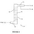
- FIG. 4is a schematic illustration of a mixing chamber of the system of FIG. 2 ;
- FIG. 5is a graph illustrating active hydrogen pressure control for achieving a constant blend ratio
- FIG. 6is a graph illustrating active hydrogen nozzle control for achieving a constant blend ratio
- FIG. 7is a schematic illustration of an alternate embodiment high pressure gas blending and compressing system
- FIG. 8is a schematic illustration of an alternate embodiment on board blending by partial pressures system
- FIG. 9is a schematic illustration of an alternate embodiment stationary blending by partial pressures system.
- FIG. 10is a schematic illustration of an alternate embodiment on board blending by partial pressures system by monitoring changes in stationary refueling receptacles.
- low pressuremeans a pressure between about 0.1 MPa (Pascals) to 1.0 MPa (Pascals).
- High pressuremeans a pressure between about 10 MPa (Pascals) to 100 MPa (Pascals).
- a gas blender 10includes a first inlet chamber 12 , a second inlet chamber 14 and a blending chamber 16 . Regulated supplies of the gases to be mixed enter the inlet chambers 12 and 14 through inlet openings 20 , and the blended gas exits the blending chamber 16 through an outlet opening 22 .
- gas blender 10can be configured to blend any number of gases (e.g., three, four, five etc.) to produce any type of gas mixture.
- the first inlet chamber 12receives hydrogen gas
- the second inlet chamber 14receives natural gas (methane)
- the blended gascomprises HYTHANE.
- the prefix “Hy” in HYTHANEis taken from hydrogen.
- the suffix “thane” in HYTHANEis taken from methane, which is the primary constituent of natural gas.
- HYTHANEis a registered trademark of Brehon Energy PLC.
- HYTHANEtypically contains about 5% to 7% hydrogen by energy. Natural gas is typically about 90+% methane, along with small amounts of ethane, propane, higher hydrocarbons, and “inerts” like carbon dioxide or nitrogen.
- Each inlet chamber 12 , 14communicates with the blending chamber 16 via a choking device 18 .
- the choking devices 18can have any desired configuration, which is selected to achieve sonic gas flow, a substantially constant mass flow rate and a minimum upstream/downstream pressure differential. However, in addition to being dependent on the configuration of the choking devices 18 , these conditions will also be dependent on the temperature and pressure in the inlet chambers 12 , 14 .
- the choking devices 18can comprise sonic orifices, sonic nozzles, adjustable area sonic nozzles or metering valves.
- each choking device 18can comprise a hole in a flat plate having fixed dimensions and geometric shape (e.g., circular, square or rectangular).
- each choking device 18can comprise an opening with a radiused or tapered entrance contour similar to a rocket nozzle.
- each choking device 18can comprise an adjustable sonic nozzle having a nozzle area that can be actively controlled using electronic signals.
- the flow rate through the choking devices 18can be controlled as a function of various operational parameters.
- each choking device 18can comprise a metering valve, which is either manually or electronically adjustable to provide a desired flow rate.
- a low pressure gas blending and compressing system 30includes the blender 10 as previously described and a compressor 60 in flow communication with the blender 10 .
- the compressor 60is configured to compress the blended gas produced by the blender 10 to a selected pressure.
- the system 30also includes a coaxial heat exchanger 39 in fluid communication with the pressure regulators 32 and 34 .
- the heat exchanger 39is configured to substantially equalize the temperature of each gas to a selected temperature.
- the heat exchanger 39is shown separately in FIG. 3 .
- the heat exchanger 39includes a first cylindrical conduit 40 , into which hydrogen gas is received, and a second cylindrical conduit 41 , into which natural gas is received.
- the first cylindrical conduit 40is positioned within the second cylindrical conduit 41 .
- the system 30also includes a control system 42 , configured to sense operational parameters of the blender 10 and the compressor 60 , to sense one or more properties of the blended gas (e.g., thermal conductivity, composition, etc), and to control the operation of the blender 10 and the compressor 60 to maintain the quality of the blended gas.
- the control system 42can also include a mixer 44 in flow communication with the outlet 22 of the blender 10 , a processing unit 46 in flow communication with the mixer 44 , and a pair of pneumatically operated valves 48 and 50 in flow communication with the inlet chambers 12 , 14 of the blender 10 .
- the system 30also includes a high pressure storage system 62 in fluid communication with an outlet of the compressor 60 .
- the storage system 62is configured to store the blended gas for dispensing and use as a hydrogen enriched fuel in an alternative fueled vehicle (AFV).
- the storage system 62can be eliminated and the blended and compressed gas can be supplied directly to the alternative fueled vehicle (AFV).
- the blender 10is constructed and operated such that a constant flow rate of the blended gas from the blender 10 matches the minimum flow rate required by the compressor 60 at its maximum operating temperature and near its maximum output pressure.
- the output pressure of the blender 10at this flow rate, will be near maximum intake pressure of the compressor 60 .
- the compressor flowwill tend to increase. Since the blender flow is constant, the compressor intake pressure will fall, reducing compressor flow to restore the balance between blender flow and compressor flow.
- the relative sizes of the choking devices 18 and the upstream pressures of each gascan be selected such that the ratio of the gases is fixed. This ratio is termed herein as the “blend ratio”.
- the pressure of the gas in each inlet chamber 12 , 14can be set or adjusted by the pressure regulators 32 and 34 to maintain a predetermined critical pressure ratio, relative to the maximum pressure downstream from the choking devices 18 .
- the pressure of the gas in each inlet chamber 12 , 14can be twice the peak pressure downstream of the choking devices 18 for any choking device shape. Sonic nozzles are particularly efficient as choking devices requiring about 114% of downstream pressure in the inlet chambers 12 , 14 .
- the control system 42also includes a controller 64 and a sensor 66 .
- the controller 64can include a low intake pressure limit switch, a high intake pressure limit switch, a low temperature limit switch, a high temperature limit switch, a low oil pressure indicator and an oil level switch.
- the controller 64can also include various computational and memory devices such as microprocessors, DRAMS (dynamic random access memories), SRAMS (static random access memories) and ASICS (application specific integrated circuits).
- the controller 64can be configured to send and receive electronic signals to other elements of the control system 42 , and to analyse and store information in digital form.
- the sensor 66operates to sense an intake pressure of the blended gas at the intake to the compressor 60 and to determine when the intake pressure of the blended gas falls below a predetermined minimum level, and when the intake pressure of the blended gas exceeds a predetermined maximum level.
- the system 30can also include a feedback regulator 68 which operates in conjunction with the controller 64 and the sensor 66 .
- the feedback regulator 68supplements the flow of blended and mixed gas to the compressor intake with compressed gas from the storage tank 62 until the pressure at the intake to the compressor 60 exceeds the pre-determined minimum level.
- the action of the feedback regulator 68 in conjunction with sensor 66aids in start-up operation of the compressor 60 in cold conditions.
- the mixer 44includes a cylindrical chamber 70 having an inlet pipe 72 configured to receive the blended gas from the outlet opening 22 of the blender 10 .
- the mixer 44also includes an outlet pipe 74 configured to output the blended, mixed gas to the compressor 60 .
- Within the chamber 70are a number of evenly spaced agitating elements in the form of baffle plates 76 .
- Successive baffle plates 76extend from alternating sides of the chamber 70 , and each baffle plate 76 terminates short of the opposing side of the chamber 70 to create a plate opening 78 .
- the spacing between baffle plates 76 , the diameter of the inlet pipe 72 , and the diameter of the outlet pipe 74are designed so that the Reynolds number Re D is greater than or equal to 3000 to ensure that the flow of the blended gases through the mixing chamber 70 is turbulent.
- the cross sectional area of the inlet pipe 72is substantially the same as the cross sectional area of the outlet pipe 74 , and substantially the same as the cross sectional area of the plate openings 78 .
- the vertical orientation of the mixing chamber 70is effective for mixing light gases, such as hydrogen gas, with denser gases such as natural gas.
- a fraction of the mixed gas output from the outlet pipe 74can be passed to the processing unit 46 where the accuracy of the blend of the hydrogen gas with the natural gas is verified. If the blended gas does not meet a pre-requisite standard, then the processing unit 46 shuts down the system 30 by discontinuing the supply of power 56 to the compressor 60 , and discontinuing the supply of air 54 to the valves 48 and 50 . Discontinuing the supply of air closes valves 48 , 50 and stops the flow of the gases to the blender 10 .
- the processing unit 46can also be manually operated to override the compressor controller 64 .
- the following high pressure embodiments of the system 30accomplish the same end result, a vehicle tank full of HYTHANE, in various ways using high pressure sources of hydrogen and CNG (compressed natural gas).
- One objective of the high pressure embodimentsis to preserve the pressure energy of the high pressure hydrogen and CNG sources. Simply reducing pressure to the much lower pressures of typical hydrogen and natural gas sources, blending and recompressing according to the previous low pressure embodiment may not always be the most energy efficient method.
- Pure hydrogen high pressure refueling equipmenthas been installed at locations that also have high pressure natural gas refueling equipment.
- refueling equipmentmeans compressors, storage tanks, dispensers, and associated gas handling apparatus.
- the following high pressure embodimentsdisclose various methods for blending HYTHANE from these high pressure sources of hydrogen and natural gas with minimal additional investment and minimal added compression energy costs.
- the natural gas (methane) source upstream of a choking device(e.g., choking devices 18 — FIG. 2 ) does necessarily need to be regulated—it is generally kept at a pressure higher than the final desired fill pressure for a quicker refilling cycle, and the fuel filling process is automatically shut-off when the vehicle tank (or a HYTHANE storage cascade) is considered ‘full’.
- the hydrogen supply pressuremust be regulated relative to the natural gas supply pressure (at a minimum, dome-loaded to follow the natural gas supply pressure).
- either the hydrogen supply pressure or the hydrogen choking devicemust be actively controlled to account for the compressibility Z differences between methane and hydrogen as the supply pressures vary.
- Example curves shown in FIGS. 5 and 6illustrate the pressure ratio that must be maintained between the hydrogen and the methane.
- the choking devicese.g., choking devices 18 — FIG. 2
- the normalized hydrogen nozzle area vs. methane supply pressureis illustrated.
- FIG. 7illustrates a high pressure system 30 A in which the compressor 60 ( FIG. 2 ) has been eliminated, and a mixer 44 A replaces the blender 10 ( FIG. 2 ).
- the mixer 44 Acan be constructed substantially as previously described for the mixer 44 ( FIG. 2 ).
- the high pressure system 30 Aincludes a control system 42 A constructed substantially as previously described for control system 42 ( FIG. 2 ).
- the high pressure system 30 Aalso includes a hydrogen supply 38 A, a natural gas supply 36 A, and a heat exchanger 39 A constructed substantially as previously described for hydrogen supply 38 ( FIG. 2 ), natural gas supply 36 ( FIG. 2 ) and heat exchanger 39 ( FIG. 2 ).
- the high pressure system 30 Aalso includes a hydrogen pressure regulator 32 A substantially similar to the pressure regulator 32 ( FIG. 2 ), which can be actively controlled by the control system 42 A.
- the high pressure system 30 Aalso includes choking devices 18 A in the form of adjustable sonic nozzles that can be actively controlled by the control system 42 A.
- a high pressure partial pressure system 30 Bincludes a high pressure hydrogen supply 36 B and a high pressure natural gas supply 38 B.
- the system 30 Balso includes a control system 42 B configured to control filling of a vehicle tank 80 B using partial pressures as will be further described.
- the system 30 Balso includes a quality control system 82 B in the form of a specimen tank for extracting and evaluating specimens of the blended gas.
- a high pressure partial pressure system 30 Cincludes a high pressure hydrogen supply 36 C and a high pressure natural gas supply 38 C.
- the system 30 Calso includes a control system 42 C configured to control filling of a high pressure storage vessel 84 C and then a vehicle tank 80 C using partial pressures as will be further described.
- the system 30 Calso includes a quality control system 82 B for extracting and evaluating specimens of the blended gas.
- a high pressure partial pressure system 30 Dincludes a high pressure hydrogen supply 36 D and a high pressure natural gas supply 38 D.
- the system 30 Dalso includes a control system 42 D configured to control filling of a vehicle tank 80 D using partial pressures measured in the hydrogen supply 36 D and the natural gas supply 38 D.
- the system 30 Dalso includes a quality control system 82 D for extracting and evaluating specimens of the blended gas. In this embodiment all of the pressure measurements are made on the hydrogen supply 36 D and the natural gas supply 38 D, rather than on the vehicle tank 80 D as in the system 30 B ( FIG. 8 ).
- the systems 30 B ( FIG. 8 ), 30 C ( FIG. 9) and 30D ( FIG. 10 )can be controlled and operated as follows.
- the concentration of each gas in the mixtureis represented by its partial pressure.
- ideal gas A and ideal Gas Bexist as a 50/50 mole fraction (AKA volume percent) mixture at a total pressure of 10 MPa, we may say that the partial pressure of A is 5 MPa and the partial pressure of B is 5 MPa.
- This ideal gas mixturecan be prepared in an empty tank by filling it at constant temperature to 5 MPa with A, and further filling the tank at constant temperature with B until the total pressure of A plus B reaches 10 MPa.
- PV/RT1
- Ppressure in Pa (Pascals)
- m 3volume in cubic meters
- Tis the absolute temperature in Kelvins (K)
- R8.3145 (Pa ⁇ m 3 )/(mol ⁇ K).
- Zaffects the pressures applied to achieve the desired mole percent.
- the HYTHANE Co. partial pressure blending modeltakes account of variations in Z mix with pressure, temperature and concentrations of hydrogen in natural gas to arrive at the desired mole ratio of hydrogen in natural gas.
- n mixP mix /Z mix ( V/RT )
- the final condition after refuelinghas the same target of 1 mole of A for every 4 moles of B.
- the tankalso has a rated capacity, stated in terms of “settled” pressure and temperature, e.g., 25 MPa @ 21° C. That corresponds to a fixed number of moles of each gas in the tank at the end of refueling. We can calculate that number by knowing Z mix for the mixture at that pressure and temperature.
- n Af( f A P settled /Z mix ) ⁇ ( V/RT settled )
- n Bf( f B P settled /Z mix ) ⁇ ( V/RT settled )
- n Af ⁇ n Ai and (n Bf ⁇ n Bi )are the numbers of moles of each gas to be added to fill the tank.
- a cascade of storage tankscan be located at a refueling station as described in previously incorporated U.S. application Ser. No. 11/348,193. At least the final stage of the cascade can be kept at a significantly higher pressure than the maximum pressure of a vehicle fuel tank in order to dispense fuel quickly from the dispensing system into the vehicle fuel tank.
Landscapes
- Chemical & Material Sciences (AREA)
- Chemical Kinetics & Catalysis (AREA)
- Dispersion Chemistry (AREA)
- Physics & Mathematics (AREA)
- General Physics & Mathematics (AREA)
- Engineering & Computer Science (AREA)
- Automation & Control Theory (AREA)
- Accessories For Mixers (AREA)
- Filling Or Discharging Of Gas Storage Vessels (AREA)
Abstract
Description
nmix=Pmix/Zmix(V/RT)
fA=1/5=0.2
fB=4/5=0.8
nAi=(fAPimix/Zmix)×(V/RTi)
nBi=(fBPimix/Zmix)×(V/RTi)
nAf=(fAPsettled/Zmix)×(V/RTsettled)
nBf=(fBPsettled/Zmix)×(V/RTsettled)
—nH2=[PiH2/ZiH2(VH2 Source/RTiH2)]−[PfH2/ZfH2(VH2 Source/RTfH2)]
—nNG=[PiNG/ZiNG(VNG Source/RTiNG)]−[PfNG/ZfNG(VNG Source/RTfNG)]
- 1a. Known vehicle tank temperature(s)—along with partial pressures and real gas properties, allows calculation and confirmation of proper blend ratio.
- 1b. Known vehicle tank temperature(s) and volume(s)—along with partial pressures and real gas properties, allows calculation and confirmation of proper blend ratio and vehicle fuel fill quantity (metering).
- 2a. Known CNG and H2 source tank temperature(s)—along with pressure changes and real gas properties, allows calculation and confirmation of proper blend ratio. No compression into sources allowed during vehicle filling process.
- 2b. Known CNG and H2 source tank temperature(s) and volume(s)—along with pressure changes and real gas properties, allows calculation and confirmation of proper blend ratio and vehicle fuel fill quantity (metering). No compression into sources allowed during vehicle filling process.
- 1a. Known HYTHANE storage cascade tank temperature(s): along with pressure changes and real gas properties, allows calculation and confirmation of proper blend ratio. Compression into sources is allowed during HYTHANE cascade filling process. Vehicle refueling is not allowed during HYTHANE cascade filling process.
- 1b. Known CNG and H2 storage cascade tank temperature(s) and volume(s): along with pressure changes and real gas properties, allows calculation and confirmation of proper blend ratio and vehicle fuel fill quantity (metering). Compression into sources is allowed during HYTHANE cascade filling process. Vehicle refueling is not allowed during HYTHANE cascade filling process.
Claims (15)
Applications Claiming Priority (2)
| Application Number | Priority Date | Filing Date | Title |
|---|---|---|---|
| AU2005902083AAU2005902083A0 (en) | 2005-04-26 | A gas blending and compression system | |
| AU2005902083 | 2005-04-26 |
Publications (2)
| Publication Number | Publication Date |
|---|---|
| US20060263283A1 US20060263283A1 (en) | 2006-11-23 |
| US7740031B2true US7740031B2 (en) | 2010-06-22 |
Family
ID=37448493
Family Applications (1)
| Application Number | Title | Priority Date | Filing Date |
|---|---|---|---|
| US11/411,766Active2027-08-27US7740031B2 (en) | 2005-04-26 | 2006-04-26 | System for blending and compressing gases |
Country Status (2)
| Country | Link |
|---|---|
| US (1) | US7740031B2 (en) |
| WO (1) | WO2007044073A2 (en) |
Cited By (6)
| Publication number | Priority date | Publication date | Assignee | Title |
|---|---|---|---|---|
| US20120312418A1 (en)* | 2011-06-09 | 2012-12-13 | L'air Liquide, Societe Anonyme Pour I'etude Et I'exploitation Des Procedes Georges Claude | Installation for packaging no using mass flow meters |
| US8418732B2 (en)* | 2011-07-06 | 2013-04-16 | Air Products And Chemicals, Inc. | Blending compressed gases |
| US20130263609A1 (en)* | 2012-04-04 | 2013-10-10 | Gp Strategies Corporation | Pumpless fluid dispenser |
| US20150285135A1 (en)* | 2014-04-04 | 2015-10-08 | Nexovation, Inc. | Combustion engine including an air injector, and power generating system including the combustion engine |
| US20210237005A1 (en)* | 2019-08-07 | 2021-08-05 | State Grid Anhui Electric Power Research Institute | Multifunctional c4f7n/co2 mixed gas preparation system and preparation method |
| US20250043739A1 (en)* | 2021-09-22 | 2025-02-06 | Bedrock Ventures LLC | Standby fuel storage system for uninterrupted operation during primary fuel curtailment |
Families Citing this family (32)
| Publication number | Priority date | Publication date | Assignee | Title |
|---|---|---|---|---|
| US7740031B2 (en) | 2005-04-26 | 2010-06-22 | Eden Innovations Ltd. | System for blending and compressing gases |
| US7547385B2 (en)* | 2005-11-14 | 2009-06-16 | Eden Innovations Ltd. | Method and system for producing a supercritical cryogenic fuel (SCCF) |
| US7497191B2 (en) | 2006-02-06 | 2009-03-03 | Eden Innovations Ltd. | System and method for producing, dispensing, using and monitoring a hydrogen enriched fuel |
| US8469009B2 (en)* | 2006-03-31 | 2013-06-25 | Westport Power Inc. | Method and apparatus of fuelling an internal combustion engine with hydrogen and methane |
| US20070277438A1 (en)* | 2006-05-30 | 2007-12-06 | Brehon Energy Plc | System and method for producing a hydrogen enriched fuel |
| US20110239959A1 (en)* | 2010-04-05 | 2011-10-06 | Chuang Shuo-Wei | Water heat source generator device |
| JP5641997B2 (en)* | 2011-03-25 | 2014-12-17 | 株式会社東芝 | Fluid mixing device and steam turbine plant |
| CN104704284B (en) | 2012-07-23 | 2017-08-08 | 弗洛吉斯蒂克公司 | Multi-stream compressor management system and method |
| US9334069B1 (en)* | 2012-10-23 | 2016-05-10 | The Boeing Company | Propellant gauging at microgravity within the pressure—temperature—density inflection zone of xenon |
| CN103234113A (en)* | 2013-04-23 | 2013-08-07 | 贵州大学 | Compressed natural gas and compressed natural gas doped coke oven gas combined refueling station |
| US20140358304A1 (en)* | 2013-06-03 | 2014-12-04 | Tescom Corporation | Method and Apparatus for Managing Fluid Supply in a Process Control System |
| CN103691042B (en)* | 2013-12-03 | 2017-03-08 | 上海力申科学仪器有限公司 | Medical gases mixing arrangement |
| CN103742781B (en)* | 2013-12-13 | 2016-06-01 | 山西省国新能源发展集团有限公司 | The refueling system of the mixed Sweet natural gas of automatic adjustable type coke-oven gas |
| US20160024409A1 (en)* | 2014-03-20 | 2016-01-28 | Pride of the Hills Manufacturing, Inc. | Gas processing system and method for blending wet well head natural gas with compressed natural gas |
| US20150267136A1 (en)* | 2014-03-20 | 2015-09-24 | Pride of the Hills Manufacturing, Inc. | Gas processing system and method for blending wet well head natural gas with compressed natural gas |
| US11433210B2 (en)* | 2014-05-27 | 2022-09-06 | Fisher & Paykel Healthcare Limited | Gases mixing and measuring for a medical device |
| US11395897B1 (en) | 2014-06-27 | 2022-07-26 | Orlando Morejon | Connector assembly for a medical ventilator system |
| DE102017102446A1 (en)* | 2016-09-15 | 2018-03-15 | Netzsch - Gerätebau Gesellschaft mit beschränkter Haftung | Method and apparatus for generating a continuous carrier gas / vapor mixture stream |
| US11471840B2 (en)* | 2018-12-18 | 2022-10-18 | Billups-Rothenberg, Inc. | Gas mixing system |
| US11774990B2 (en) | 2019-12-30 | 2023-10-03 | Marathon Petroleum Company Lp | Methods and systems for inline mixing of hydrocarbon liquids based on density or gravity |
| US11655940B2 (en) | 2021-03-16 | 2023-05-23 | Marathon Petroleum Company Lp | Systems and methods for transporting fuel and carbon dioxide in a dual fluid vessel |
| US11578638B2 (en) | 2021-03-16 | 2023-02-14 | Marathon Petroleum Company Lp | Scalable greenhouse gas capture systems and methods |
| US12180597B2 (en) | 2021-08-26 | 2024-12-31 | Marathon Petroleum Company Lp | Test station assemblies for monitoring cathodic protection of structures and related methods |
| US11686070B1 (en) | 2022-05-04 | 2023-06-27 | Marathon Petroleum Company Lp | Systems, methods, and controllers to enhance heavy equipment warning |
| US12129807B2 (en)* | 2022-05-05 | 2024-10-29 | Caterpillar Inc. | Dual fuel engine operating strategy for optimized hydrogen and hydrocarbon fueling |
| US11681307B1 (en)* | 2022-05-20 | 2023-06-20 | Digital Stream Energy, Inc. | Systems and methods for fuel-gas blending |
| US12006014B1 (en) | 2023-02-18 | 2024-06-11 | Marathon Petroleum Company Lp | Exhaust vent hoods for marine vessels and related methods |
| US12043361B1 (en) | 2023-02-18 | 2024-07-23 | Marathon Petroleum Company Lp | Exhaust handling systems for marine vessels and related methods |
| US20240302000A1 (en)* | 2023-03-07 | 2024-09-12 | Boyd Hydrogen LLC | Compressed hydrogen vehicle fueling system having sonic choke flow control |
| IT202300010056A1 (en)* | 2023-05-18 | 2024-11-18 | Antares Vision S P A | EQUIPMENT FOR FILLING CALIBRATION CONTAINERS FOR OXYGEN DETECTION SYSTEMS |
| US12297965B2 (en)* | 2023-08-09 | 2025-05-13 | Marathon Petroleum Company Lp | Systems and methods for mixing hydrogen with natural gas |
| CN119513455B (en)* | 2025-01-15 | 2025-04-25 | 正帆科技(湖州)有限公司 | Gas mixing cabinet operation parameter correction system and method based on big data |
Citations (56)
| Publication number | Priority date | Publication date | Assignee | Title |
|---|---|---|---|---|
| US3762428A (en)* | 1971-11-15 | 1973-10-02 | Ocean Systems | Volumetric gas mixing system |
| US4480654A (en)* | 1982-08-26 | 1984-11-06 | Firey Joseph C | Multipressure compressor |
| US4520763A (en) | 1981-09-25 | 1985-06-04 | Ergenics Inc. | Fuel injection system |
| US4526771A (en)* | 1981-05-08 | 1985-07-02 | International Environmental, Inc. | Sulfurous acid generator |
| US4559133A (en) | 1980-05-09 | 1985-12-17 | Peter Siegfried | Process for separating liquids from fine grained solids |
| US4608830A (en) | 1983-12-10 | 1986-09-02 | Deutsche Forschungs- Und Versuchsanstalt Fur Luft- Und Raumfahrt E.V. | Method and apparatus for the automatic refilling of a liquid hydrogen tank in a motor vehicle |
| US5139002A (en) | 1990-10-30 | 1992-08-18 | Hydrogen Consultants, Inc. | Special purpose blends of hydrogen and natural gas |
| US5183011A (en) | 1991-04-17 | 1993-02-02 | Honda Giken Kogyo Kabushiki Kaisha | Method of controlling the supply of fuel in hydrogen-fueled engine |
| US5512787A (en) | 1994-10-19 | 1996-04-30 | Dederick; Robert | Facility for refueling of clean air vehicles/marine craft and power generation |
| US5516967A (en) | 1995-01-30 | 1996-05-14 | Chemisar Laboratories Inc. | Direct conversion of methane to hythane |
| US5529484A (en) | 1993-11-08 | 1996-06-25 | Moard; David M. | Apparatus and method for decreasing nitrogen oxide emissions from internal combustion power sources |
| US5558783A (en) | 1993-02-05 | 1996-09-24 | Mcguinness; Thomas G. | Supercritical oxidation reactor |
| US5660602A (en) | 1994-05-04 | 1997-08-26 | University Of Central Florida | Hydrogen enriched natural gas as a clean motor fuel |
| US5666923A (en) | 1994-05-04 | 1997-09-16 | University Of Central Florida | Hydrogen enriched natural gas as a motor fuel with variable air fuel ratio and fuel mixture ratio control |
| US5687776A (en) | 1992-12-07 | 1997-11-18 | Chicago Bridge & Iron Technical Services Company | Method and apparatus for fueling vehicles with liquefied cryogenic fuel |
| US5705771A (en) | 1990-10-29 | 1998-01-06 | Flynn; Thomas M. | Cryogenic propellants and method for producing cryogenic propellants |
| US5771857A (en) | 1996-11-06 | 1998-06-30 | Caterpillar Inc. | Direct injected gas engine with variable gas pressure control apparatus and method of operation |
| US5787864A (en) | 1995-04-25 | 1998-08-04 | University Of Central Florida | Hydrogen enriched natural gas as a motor fuel with variable air fuel ratio and fuel mixture ratio control |
| US5804760A (en) | 1997-06-23 | 1998-09-08 | Cryoco, Inc. | Method for making and storing cryogenic monopropellant |
| US5826632A (en)* | 1997-05-30 | 1998-10-27 | The Boc Group, Inc. | Dynamic gas cylinder filling process |
| US5868133A (en)* | 1994-10-14 | 1999-02-09 | Bird Products Corporation | Portable drag compressor powered mechanical ventilator |
| US5887567A (en) | 1993-11-26 | 1999-03-30 | White; George W. | Natural gas fueling system |
| US6058713A (en) | 1997-06-20 | 2000-05-09 | Exxonmobil Upstream Research Company | LNG fuel storage and delivery systems for natural gas powered vehicles |
| US6105631A (en)* | 1996-11-28 | 2000-08-22 | Solvay Fluor Und Derivate Gmbh | Preparation of homogeneous gas mixtures with SF6 |
| US6152192A (en) | 1998-02-11 | 2000-11-28 | Welding Company Of America | Controller for system for filling gas cylinders with single gas or gas mixture |
| US6273076B1 (en) | 1997-12-16 | 2001-08-14 | Servojet Products International | Optimized lambda and compression temperature control for compression ignition engines |
| US6311648B1 (en) | 2000-02-22 | 2001-11-06 | Jean-Louis Larocque | Hydrogen-oxygen/hydrocarbon fuel system for internal combustion engine |
| US6327856B1 (en) | 1999-02-26 | 2001-12-11 | Mitsubishi Jidosha Kogyo Kabushiki Kaisha | Control apparatus and method for premixed compression ignition type internal combustion engines |
| US6378308B1 (en) | 1998-04-16 | 2002-04-30 | 3K Warner Turbosystems Gmbh | Turbocharged internal combustion engine |
| US6508209B1 (en) | 2000-04-03 | 2003-01-21 | R. Kirk Collier, Jr. | Reformed natural gas for powering an internal combustion engine |
| US20030051486A1 (en) | 2001-09-19 | 2003-03-20 | Mihai Ursan | Method and apparatus for pumping a cryogenic fluid from a storage tank |
| US20030177785A1 (en) | 2002-03-20 | 2003-09-25 | Kimble E. Lawrence | Process for producing a pressurized liquefied gas product by cooling and expansion of a gas stream in the supercritical state |
| US20030209211A1 (en) | 2002-02-19 | 2003-11-13 | Collier R. Kirk | Low-emission internal combustion engine |
| US6651623B1 (en) | 2002-08-01 | 2003-11-25 | Ford Global Technologies, Llc | Method and system for measuring air/fuel ratio in a hydrogen fueled internal combustion engine |
| US6739125B1 (en) | 2002-11-13 | 2004-05-25 | Collier Technologies, Inc. | Internal combustion engine with SCR and integrated ammonia production |
| US6745613B2 (en) | 2001-08-13 | 2004-06-08 | Spx Corporation | Method and system for determining the type of fuel used to power a vehicle |
| US6758593B1 (en) | 2000-10-09 | 2004-07-06 | Levtech, Inc. | Pumping or mixing system using a levitating magnetic element, related system components, and related methods |
| US6779337B2 (en) | 2002-09-20 | 2004-08-24 | Ford Global Technologies, Llc | Hydrogen fueled spark ignition engine |
| US6827084B2 (en)* | 2002-06-21 | 2004-12-07 | Lloyd Thomas Grubb, Jr. | Automatic gas blender |
| US20040244280A1 (en) | 2003-06-03 | 2004-12-09 | Southwest Research Institute | Method for improving the performance of engines powered by liquid hydrocarbon fuel |
| US6834508B2 (en) | 2002-08-29 | 2004-12-28 | Nanomix, Inc. | Hydrogen storage and supply system |
| US20050016507A1 (en) | 2003-01-10 | 2005-01-27 | Tamol Ronald A. | Method and apparatus to increase combustion efficiency and to reduce exhaust gas pollutants from combustion of a fuel |
| US20050027592A1 (en) | 2003-07-30 | 2005-02-03 | Pettigrew F. Alexander | Powered platform fuel consumption economy credits method |
| US20050031918A1 (en) | 2003-08-07 | 2005-02-10 | Cbh2 Technologies, Inc. | Hypergolic hydrogen generation system for fuel cell power plants |
| US6901952B2 (en) | 2000-06-23 | 2005-06-07 | Teleflex Gfi Control Systems L.P. | Gas flow regulation system |
| US20050188683A1 (en) | 2004-02-26 | 2005-09-01 | Mazda Motor Corporation | Control device of hydrogen engine |
| US6951765B1 (en) | 2001-12-12 | 2005-10-04 | Novellus Systems, Inc. | Method and apparatus for introduction of solid precursors and reactants into a supercritical fluid reactor |
| US20050224045A1 (en) | 2004-04-08 | 2005-10-13 | Hiroshi Kuzuyama | Homogeneous charge compression ignition engine and method for operating homogeneous charge compression ignition engine |
| US20060263283A1 (en) | 2005-04-26 | 2006-11-23 | Egan Gregory J | System and method for blending and compressing gases |
| US7168464B2 (en)* | 2004-09-09 | 2007-01-30 | Pinnacle Cng Systems, Llc | Dual-service system and method for compressing and dispensing natural gas and hydrogen |
| US20070039598A1 (en) | 2005-08-18 | 2007-02-22 | Mazda Motor Corporation | Control of lean burn engine using exhaust gas recirculation |
| US7201159B2 (en) | 2003-03-14 | 2007-04-10 | Siemens Canada Limited | Electric actuator assembly and method for controlling an exhaust gas recirculation assembly |
| US20070108096A1 (en) | 2005-11-14 | 2007-05-17 | Egan Gregory J | Method and system for producing a supercritical cryogenic fuel (SCCF) |
| US7240641B2 (en) | 2001-01-19 | 2007-07-10 | Hy-Drive Technologies Ltd. | Hydrogen generating apparatus and components therefor |
| US20070181083A1 (en) | 2006-02-06 | 2007-08-09 | Brehon Energy Plc | System and method for producing, dispensing, using and monitoring a hydrogen enriched fuel |
| US20070277438A1 (en) | 2006-05-30 | 2007-12-06 | Brehon Energy Plc | System and method for producing a hydrogen enriched fuel |
Family Cites Families (1)
| Publication number | Priority date | Publication date | Assignee | Title |
|---|---|---|---|---|
| US7398499B2 (en)* | 2006-05-24 | 2008-07-08 | Chang Gung University | Method of searching paths suffering from the electrostatic discharge in the process of an integrated circuit design |
- 2006
- 2006-04-26USUS11/411,766patent/US7740031B2/enactiveActive
- 2006-04-26WOPCT/US2006/015663patent/WO2007044073A2/enactiveApplication Filing
Patent Citations (61)
| Publication number | Priority date | Publication date | Assignee | Title |
|---|---|---|---|---|
| US3762428A (en)* | 1971-11-15 | 1973-10-02 | Ocean Systems | Volumetric gas mixing system |
| US4559133A (en) | 1980-05-09 | 1985-12-17 | Peter Siegfried | Process for separating liquids from fine grained solids |
| US4526771A (en)* | 1981-05-08 | 1985-07-02 | International Environmental, Inc. | Sulfurous acid generator |
| US4520763A (en) | 1981-09-25 | 1985-06-04 | Ergenics Inc. | Fuel injection system |
| US4480654A (en)* | 1982-08-26 | 1984-11-06 | Firey Joseph C | Multipressure compressor |
| US4608830A (en) | 1983-12-10 | 1986-09-02 | Deutsche Forschungs- Und Versuchsanstalt Fur Luft- Und Raumfahrt E.V. | Method and apparatus for the automatic refilling of a liquid hydrogen tank in a motor vehicle |
| US5705771A (en) | 1990-10-29 | 1998-01-06 | Flynn; Thomas M. | Cryogenic propellants and method for producing cryogenic propellants |
| US5139002A (en) | 1990-10-30 | 1992-08-18 | Hydrogen Consultants, Inc. | Special purpose blends of hydrogen and natural gas |
| US5183011A (en) | 1991-04-17 | 1993-02-02 | Honda Giken Kogyo Kabushiki Kaisha | Method of controlling the supply of fuel in hydrogen-fueled engine |
| US5687776A (en) | 1992-12-07 | 1997-11-18 | Chicago Bridge & Iron Technical Services Company | Method and apparatus for fueling vehicles with liquefied cryogenic fuel |
| US5558783A (en) | 1993-02-05 | 1996-09-24 | Mcguinness; Thomas G. | Supercritical oxidation reactor |
| US5529484A (en) | 1993-11-08 | 1996-06-25 | Moard; David M. | Apparatus and method for decreasing nitrogen oxide emissions from internal combustion power sources |
| US5887567A (en) | 1993-11-26 | 1999-03-30 | White; George W. | Natural gas fueling system |
| US5660602A (en) | 1994-05-04 | 1997-08-26 | University Of Central Florida | Hydrogen enriched natural gas as a clean motor fuel |
| US5666923A (en) | 1994-05-04 | 1997-09-16 | University Of Central Florida | Hydrogen enriched natural gas as a motor fuel with variable air fuel ratio and fuel mixture ratio control |
| US5868133A (en)* | 1994-10-14 | 1999-02-09 | Bird Products Corporation | Portable drag compressor powered mechanical ventilator |
| US5512787A (en) | 1994-10-19 | 1996-04-30 | Dederick; Robert | Facility for refueling of clean air vehicles/marine craft and power generation |
| US5516967A (en) | 1995-01-30 | 1996-05-14 | Chemisar Laboratories Inc. | Direct conversion of methane to hythane |
| US5787864A (en) | 1995-04-25 | 1998-08-04 | University Of Central Florida | Hydrogen enriched natural gas as a motor fuel with variable air fuel ratio and fuel mixture ratio control |
| US5771857A (en) | 1996-11-06 | 1998-06-30 | Caterpillar Inc. | Direct injected gas engine with variable gas pressure control apparatus and method of operation |
| US6105631A (en)* | 1996-11-28 | 2000-08-22 | Solvay Fluor Und Derivate Gmbh | Preparation of homogeneous gas mixtures with SF6 |
| US5826632A (en)* | 1997-05-30 | 1998-10-27 | The Boc Group, Inc. | Dynamic gas cylinder filling process |
| US6058713A (en) | 1997-06-20 | 2000-05-09 | Exxonmobil Upstream Research Company | LNG fuel storage and delivery systems for natural gas powered vehicles |
| US5804760A (en) | 1997-06-23 | 1998-09-08 | Cryoco, Inc. | Method for making and storing cryogenic monopropellant |
| US6273076B1 (en) | 1997-12-16 | 2001-08-14 | Servojet Products International | Optimized lambda and compression temperature control for compression ignition engines |
| US6152192A (en) | 1998-02-11 | 2000-11-28 | Welding Company Of America | Controller for system for filling gas cylinders with single gas or gas mixture |
| US6378308B1 (en) | 1998-04-16 | 2002-04-30 | 3K Warner Turbosystems Gmbh | Turbocharged internal combustion engine |
| US6327856B1 (en) | 1999-02-26 | 2001-12-11 | Mitsubishi Jidosha Kogyo Kabushiki Kaisha | Control apparatus and method for premixed compression ignition type internal combustion engines |
| US6311648B1 (en) | 2000-02-22 | 2001-11-06 | Jean-Louis Larocque | Hydrogen-oxygen/hydrocarbon fuel system for internal combustion engine |
| US6508209B1 (en) | 2000-04-03 | 2003-01-21 | R. Kirk Collier, Jr. | Reformed natural gas for powering an internal combustion engine |
| US6901952B2 (en) | 2000-06-23 | 2005-06-07 | Teleflex Gfi Control Systems L.P. | Gas flow regulation system |
| US6758593B1 (en) | 2000-10-09 | 2004-07-06 | Levtech, Inc. | Pumping or mixing system using a levitating magnetic element, related system components, and related methods |
| US7240641B2 (en) | 2001-01-19 | 2007-07-10 | Hy-Drive Technologies Ltd. | Hydrogen generating apparatus and components therefor |
| US6745613B2 (en) | 2001-08-13 | 2004-06-08 | Spx Corporation | Method and system for determining the type of fuel used to power a vehicle |
| US20030051486A1 (en) | 2001-09-19 | 2003-03-20 | Mihai Ursan | Method and apparatus for pumping a cryogenic fluid from a storage tank |
| US6951765B1 (en) | 2001-12-12 | 2005-10-04 | Novellus Systems, Inc. | Method and apparatus for introduction of solid precursors and reactants into a supercritical fluid reactor |
| US6823852B2 (en) | 2002-02-19 | 2004-11-30 | Collier Technologies, Llc | Low-emission internal combustion engine |
| US20030209211A1 (en) | 2002-02-19 | 2003-11-13 | Collier R. Kirk | Low-emission internal combustion engine |
| US20030177785A1 (en) | 2002-03-20 | 2003-09-25 | Kimble E. Lawrence | Process for producing a pressurized liquefied gas product by cooling and expansion of a gas stream in the supercritical state |
| US6827084B2 (en)* | 2002-06-21 | 2004-12-07 | Lloyd Thomas Grubb, Jr. | Automatic gas blender |
| US6651623B1 (en) | 2002-08-01 | 2003-11-25 | Ford Global Technologies, Llc | Method and system for measuring air/fuel ratio in a hydrogen fueled internal combustion engine |
| US6834508B2 (en) | 2002-08-29 | 2004-12-28 | Nanomix, Inc. | Hydrogen storage and supply system |
| US6779337B2 (en) | 2002-09-20 | 2004-08-24 | Ford Global Technologies, Llc | Hydrogen fueled spark ignition engine |
| US20040237512A1 (en) | 2002-09-20 | 2004-12-02 | Ford Global Technologies Llc | Hydrogen fueled spark ignition engine |
| US6739125B1 (en) | 2002-11-13 | 2004-05-25 | Collier Technologies, Inc. | Internal combustion engine with SCR and integrated ammonia production |
| US20050016507A1 (en) | 2003-01-10 | 2005-01-27 | Tamol Ronald A. | Method and apparatus to increase combustion efficiency and to reduce exhaust gas pollutants from combustion of a fuel |
| US7201159B2 (en) | 2003-03-14 | 2007-04-10 | Siemens Canada Limited | Electric actuator assembly and method for controlling an exhaust gas recirculation assembly |
| US20040244280A1 (en) | 2003-06-03 | 2004-12-09 | Southwest Research Institute | Method for improving the performance of engines powered by liquid hydrocarbon fuel |
| US20050027592A1 (en) | 2003-07-30 | 2005-02-03 | Pettigrew F. Alexander | Powered platform fuel consumption economy credits method |
| US20050031918A1 (en) | 2003-08-07 | 2005-02-10 | Cbh2 Technologies, Inc. | Hypergolic hydrogen generation system for fuel cell power plants |
| US20050188683A1 (en) | 2004-02-26 | 2005-09-01 | Mazda Motor Corporation | Control device of hydrogen engine |
| US7111452B2 (en) | 2004-02-26 | 2006-09-26 | Mazda Motor Corporation | Control device of hydrogen engine |
| US20050224045A1 (en) | 2004-04-08 | 2005-10-13 | Hiroshi Kuzuyama | Homogeneous charge compression ignition engine and method for operating homogeneous charge compression ignition engine |
| US7168464B2 (en)* | 2004-09-09 | 2007-01-30 | Pinnacle Cng Systems, Llc | Dual-service system and method for compressing and dispensing natural gas and hydrogen |
| US20060263283A1 (en) | 2005-04-26 | 2006-11-23 | Egan Gregory J | System and method for blending and compressing gases |
| US20070039598A1 (en) | 2005-08-18 | 2007-02-22 | Mazda Motor Corporation | Control of lean burn engine using exhaust gas recirculation |
| US20070108096A1 (en) | 2005-11-14 | 2007-05-17 | Egan Gregory J | Method and system for producing a supercritical cryogenic fuel (SCCF) |
| US20070181083A1 (en) | 2006-02-06 | 2007-08-09 | Brehon Energy Plc | System and method for producing, dispensing, using and monitoring a hydrogen enriched fuel |
| US20080216774A1 (en) | 2006-02-06 | 2008-09-11 | Justin Fulton | System For Producing A Hydrogen Enriched Fuel |
| US7497191B2 (en) | 2006-02-06 | 2009-03-03 | Eden Innovations Ltd. | System and method for producing, dispensing, using and monitoring a hydrogen enriched fuel |
| US20070277438A1 (en) | 2006-05-30 | 2007-12-06 | Brehon Energy Plc | System and method for producing a hydrogen enriched fuel |
Non-Patent Citations (8)
| Title |
|---|
| Basye, Leon et al, "Hydrogen Production Costs-A Survey", Dec. 4, 1997, pp. 1-10, Sentech, Inc., Bethesda, MD. |
| Office Action dated Jun. 9, 2009 from U.S. Appl. No. 12/120,438, pp. 1-10. |
| Office Action dated Mar. 21, 2008 from U.S. Appl. No. 11/348,193. |
| Office Action dated May 23, 2008 from U.S. Appl. No. 11/348,193. |
| Office Action dated Sep. 25, 2007 from U.S. Appl. No. 11/348,193. |
| PCT Search Report and Written Opinion in International Application No. PCT/US06/15663 dated Apr. 27, 2007. |
| U.S. Appl. No. 11/273,397, filed Nov. 14, 2005, Rudland et al. |
| U.S. Appl. No. 11/348,193, filed Feb. 6, 2006, Fulton et al. |
Cited By (10)
| Publication number | Priority date | Publication date | Assignee | Title |
|---|---|---|---|---|
| US20120312418A1 (en)* | 2011-06-09 | 2012-12-13 | L'air Liquide, Societe Anonyme Pour I'etude Et I'exploitation Des Procedes Georges Claude | Installation for packaging no using mass flow meters |
| US8636040B2 (en)* | 2011-06-09 | 2014-01-28 | L'Air Liquide, Société Anonyme pour l'Etude et l'Exploitation des Procédés Georges Claude | Installation for packaging NO using mass flow meters |
| US8418732B2 (en)* | 2011-07-06 | 2013-04-16 | Air Products And Chemicals, Inc. | Blending compressed gases |
| KR101397862B1 (en)* | 2011-07-06 | 2014-05-20 | 에어 프로덕츠 앤드 케미칼스, 인코오포레이티드 | Method and apparatus for mixing compressed gas |
| US20130263609A1 (en)* | 2012-04-04 | 2013-10-10 | Gp Strategies Corporation | Pumpless fluid dispenser |
| US9163785B2 (en)* | 2012-04-04 | 2015-10-20 | Gp Strategies Corporation | Pumpless fluid dispenser |
| US20150285135A1 (en)* | 2014-04-04 | 2015-10-08 | Nexovation, Inc. | Combustion engine including an air injector, and power generating system including the combustion engine |
| US20210237005A1 (en)* | 2019-08-07 | 2021-08-05 | State Grid Anhui Electric Power Research Institute | Multifunctional c4f7n/co2 mixed gas preparation system and preparation method |
| US12121870B2 (en)* | 2019-08-07 | 2024-10-22 | State Grid Anhui Electric Power Research Institute | Multifunctional C4F7N/CO2 mixed gas preparation system and preparation method |
| US20250043739A1 (en)* | 2021-09-22 | 2025-02-06 | Bedrock Ventures LLC | Standby fuel storage system for uninterrupted operation during primary fuel curtailment |
Also Published As
| Publication number | Publication date |
|---|---|
| WO2007044073A2 (en) | 2007-04-19 |
| WO2007044073A3 (en) | 2007-07-12 |
| US20060263283A1 (en) | 2006-11-23 |
Similar Documents
| Publication | Publication Date | Title |
|---|---|---|
| US7740031B2 (en) | System for blending and compressing gases | |
| CA2782040C (en) | Blending compressed gases | |
| US7328726B2 (en) | Ramp rate blender | |
| US4646940A (en) | Method and apparatus for accurately measuring volume of gas flowing as a result of differential pressure | |
| EP0578578A1 (en) | Apparatus and method for mixing gases | |
| US5143116A (en) | Flow regulating valve and system using the same | |
| CN111735520B (en) | A gas flow standard device with high and low pressure dual calibration sections and calibration method thereof | |
| EP2241810A1 (en) | Flow rate control device | |
| AU731273B2 (en) | Production of constant composition gas mixture streams | |
| CN109791099A (en) | Concentration detection method and pressure flow-rate controller | |
| EP1152818A2 (en) | Volumetric gas mixing device | |
| JP2002154974A (en) | Process and plant for dynamic packing of gas, especially those for medical use | |
| CN103644456A (en) | Sound velocity nozzle volume automatic air distributing system and control method thereof | |
| CN104568082A (en) | Supercritical CO2 flowmeter calibration device and calibration method thereof | |
| US5860407A (en) | Gaseous fuel control system for engines | |
| CN100501350C (en) | Gas flow test stand and method of operating and forming the same | |
| WO2012050790A1 (en) | Low pressure drop blender | |
| CN115362427A (en) | Dosing unit for the generation of gas mixtures | |
| AU2017200351A1 (en) | Gas dilution system | |
| CN223435008U (en) | Working medium filling device based on phase state control | |
| CN203703615U (en) | Automatic gas distribution system for volume of sonic nozzle | |
| CN219913697U (en) | Supercooled liquid oxygen preparation system | |
| CN119468072B (en) | A wide flow and accurate natural gas hydrogen blending device and natural gas hydrogen blending method | |
| JPH11106768A (en) | Apparatus for producing propane air 13a | |
| MacDonald et al. | Air and Nitrogen Testing of Coriolis Flow Meters Designed for Hydrogen Refuelling Stations |
Legal Events
| Date | Code | Title | Description |
|---|---|---|---|
| AS | Assignment | Owner name:EDEN INNOVATIONS LTD, IRELAND Free format text:CHANGE OF NAME;ASSIGNOR:BREHON ENERGY PLC;REEL/FRAME:020142/0692 Effective date:20070321 Owner name:EDEN INNOVATIONS LTD,IRELAND Free format text:CHANGE OF NAME;ASSIGNOR:BREHON ENERGY PLC;REEL/FRAME:020142/0692 Effective date:20070321 | |
| FEPP | Fee payment procedure | Free format text:PAYOR NUMBER ASSIGNED (ORIGINAL EVENT CODE: ASPN); ENTITY STATUS OF PATENT OWNER: SMALL ENTITY Free format text:PAYER NUMBER DE-ASSIGNED (ORIGINAL EVENT CODE: RMPN); ENTITY STATUS OF PATENT OWNER: SMALL ENTITY | |
| AS | Assignment | Owner name:EDEN INNOVATIONS LTD.,IRELAND Free format text:ASSIGNMENT OF ASSIGNORS INTEREST;ASSIGNORS:EGAN, GREGORY J.;FULTON, JUSTIN;MARMARO, ROGER W.;AND OTHERS;SIGNING DATES FROM 20100407 TO 20100505;REEL/FRAME:024356/0724 | |
| STCF | Information on status: patent grant | Free format text:PATENTED CASE | |
| AS | Assignment | Owner name:EDEN ENERGY LTD., AUSTRALIA Free format text:ASSIGNMENT OF ASSIGNORS INTEREST;ASSIGNOR:EDEN INNOVATIONS LTD.;REEL/FRAME:028967/0483 Effective date:20120914 | |
| FPAY | Fee payment | Year of fee payment:4 | |
| MAFP | Maintenance fee payment | Free format text:PAYMENT OF MAINTENANCE FEE, 8TH YR, SMALL ENTITY (ORIGINAL EVENT CODE: M2552) Year of fee payment:8 | |
| MAFP | Maintenance fee payment | Free format text:PAYMENT OF MAINTENANCE FEE, 12TH YR, SMALL ENTITY (ORIGINAL EVENT CODE: M2553); ENTITY STATUS OF PATENT OWNER: SMALL ENTITY Year of fee payment:12 |