US7740008B2 - Multiple height fluid mixer and method of use - Google Patents
Multiple height fluid mixer and method of useDownload PDFInfo
- Publication number
- US7740008B2 US7740008B2US11/877,315US87731507AUS7740008B2US 7740008 B2US7740008 B2US 7740008B2US 87731507 AUS87731507 AUS 87731507AUS 7740008 B2US7740008 B2US 7740008B2
- Authority
- US
- United States
- Prior art keywords
- passage
- mixer
- outlet
- exhaust gas
- outer pipe
- Prior art date
- Legal status (The legal status is an assumption and is not a legal conclusion. Google has not performed a legal analysis and makes no representation as to the accuracy of the status listed.)
- Active, expires
Links
- 239000012530fluidSubstances0.000titleclaimsdescription14
- 238000000034methodMethods0.000titleclaimsdescription11
- 239000000203mixtureSubstances0.000claimsabstractdescription22
- 238000002485combustion reactionMethods0.000description13
- 239000008240homogeneous mixtureSubstances0.000description4
- 230000000712assemblyEffects0.000description2
- 238000000429assemblyMethods0.000description2
- 238000010586diagramMethods0.000description2
- 239000000446fuelSubstances0.000description2
- 230000015572biosynthetic processEffects0.000description1
- 239000003054catalystSubstances0.000description1
- 238000004891communicationMethods0.000description1
- 230000003247decreasing effectEffects0.000description1
- 238000007789sealingMethods0.000description1
- 238000011144upstream manufacturingMethods0.000description1
Images


Classifications
- F—MECHANICAL ENGINEERING; LIGHTING; HEATING; WEAPONS; BLASTING
- F02—COMBUSTION ENGINES; HOT-GAS OR COMBUSTION-PRODUCT ENGINE PLANTS
- F02M—SUPPLYING COMBUSTION ENGINES IN GENERAL WITH COMBUSTIBLE MIXTURES OR CONSTITUENTS THEREOF
- F02M35/00—Combustion-air cleaners, air intakes, intake silencers, or induction systems specially adapted for, or arranged on, internal-combustion engines
- F02M35/10—Air intakes; Induction systems
- B—PERFORMING OPERATIONS; TRANSPORTING
- B01—PHYSICAL OR CHEMICAL PROCESSES OR APPARATUS IN GENERAL
- B01F—MIXING, e.g. DISSOLVING, EMULSIFYING OR DISPERSING
- B01F25/00—Flow mixers; Mixers for falling materials, e.g. solid particles
- B01F25/30—Injector mixers
- B01F25/31—Injector mixers in conduits or tubes through which the main component flows
- B01F25/313—Injector mixers in conduits or tubes through which the main component flows wherein additional components are introduced in the centre of the conduit
- B—PERFORMING OPERATIONS; TRANSPORTING
- B01—PHYSICAL OR CHEMICAL PROCESSES OR APPARATUS IN GENERAL
- B01F—MIXING, e.g. DISSOLVING, EMULSIFYING OR DISPERSING
- B01F23/00—Mixing according to the phases to be mixed, e.g. dispersing or emulsifying
- B01F23/10—Mixing gases with gases
- B—PERFORMING OPERATIONS; TRANSPORTING
- B01—PHYSICAL OR CHEMICAL PROCESSES OR APPARATUS IN GENERAL
- B01F—MIXING, e.g. DISSOLVING, EMULSIFYING OR DISPERSING
- B01F25/00—Flow mixers; Mixers for falling materials, e.g. solid particles
- B01F25/30—Injector mixers
- B01F25/31—Injector mixers in conduits or tubes through which the main component flows
- B01F25/313—Injector mixers in conduits or tubes through which the main component flows wherein additional components are introduced in the centre of the conduit
- B01F25/3133—Injector mixers in conduits or tubes through which the main component flows wherein additional components are introduced in the centre of the conduit characterised by the specific design of the injector
- B01F25/31331—Perforated, multi-opening, with a plurality of holes
- F—MECHANICAL ENGINEERING; LIGHTING; HEATING; WEAPONS; BLASTING
- F02—COMBUSTION ENGINES; HOT-GAS OR COMBUSTION-PRODUCT ENGINE PLANTS
- F02B—INTERNAL-COMBUSTION PISTON ENGINES; COMBUSTION ENGINES IN GENERAL
- F02B29/00—Engines characterised by provision for charging or scavenging not provided for in groups F02B25/00, F02B27/00 or F02B33/00 - F02B39/00; Details thereof
- F02B29/02—Other fluid-dynamic features of induction systems for improving quantity of charge
- F—MECHANICAL ENGINEERING; LIGHTING; HEATING; WEAPONS; BLASTING
- F02—COMBUSTION ENGINES; HOT-GAS OR COMBUSTION-PRODUCT ENGINE PLANTS
- F02M—SUPPLYING COMBUSTION ENGINES IN GENERAL WITH COMBUSTIBLE MIXTURES OR CONSTITUENTS THEREOF
- F02M26/00—Engine-pertinent apparatus for adding exhaust gases to combustion-air, main fuel or fuel-air mixture, e.g. by exhaust gas recirculation [EGR] systems
- F02M26/13—Arrangement or layout of EGR passages, e.g. in relation to specific engine parts or for incorporation of accessories
- F02M26/17—Arrangement or layout of EGR passages, e.g. in relation to specific engine parts or for incorporation of accessories in relation to the intake system
- F02M26/19—Means for improving the mixing of air and recirculated exhaust gases, e.g. venturis or multiple openings to the intake system
- F—MECHANICAL ENGINEERING; LIGHTING; HEATING; WEAPONS; BLASTING
- F02—COMBUSTION ENGINES; HOT-GAS OR COMBUSTION-PRODUCT ENGINE PLANTS
- F02M—SUPPLYING COMBUSTION ENGINES IN GENERAL WITH COMBUSTIBLE MIXTURES OR CONSTITUENTS THEREOF
- F02M26/00—Engine-pertinent apparatus for adding exhaust gases to combustion-air, main fuel or fuel-air mixture, e.g. by exhaust gas recirculation [EGR] systems
- F02M26/13—Arrangement or layout of EGR passages, e.g. in relation to specific engine parts or for incorporation of accessories
- F02M26/42—Arrangement or layout of EGR passages, e.g. in relation to specific engine parts or for incorporation of accessories having two or more EGR passages; EGR systems specially adapted for engines having two or more cylinders
- F02M26/43—Arrangement or layout of EGR passages, e.g. in relation to specific engine parts or for incorporation of accessories having two or more EGR passages; EGR systems specially adapted for engines having two or more cylinders in which exhaust from only one cylinder or only a group of cylinders is directed to the intake of the engine
- F—MECHANICAL ENGINEERING; LIGHTING; HEATING; WEAPONS; BLASTING
- F02—COMBUSTION ENGINES; HOT-GAS OR COMBUSTION-PRODUCT ENGINE PLANTS
- F02B—INTERNAL-COMBUSTION PISTON ENGINES; COMBUSTION ENGINES IN GENERAL
- F02B29/00—Engines characterised by provision for charging or scavenging not provided for in groups F02B25/00, F02B27/00 or F02B33/00 - F02B39/00; Details thereof
- F02B29/04—Cooling of air intake supply
- F02B29/0406—Layout of the intake air cooling or coolant circuit
- F—MECHANICAL ENGINEERING; LIGHTING; HEATING; WEAPONS; BLASTING
- F02—COMBUSTION ENGINES; HOT-GAS OR COMBUSTION-PRODUCT ENGINE PLANTS
- F02M—SUPPLYING COMBUSTION ENGINES IN GENERAL WITH COMBUSTIBLE MIXTURES OR CONSTITUENTS THEREOF
- F02M26/00—Engine-pertinent apparatus for adding exhaust gases to combustion-air, main fuel or fuel-air mixture, e.g. by exhaust gas recirculation [EGR] systems
- F02M26/02—EGR systems specially adapted for supercharged engines
- F02M26/04—EGR systems specially adapted for supercharged engines with a single turbocharger
- F02M26/05—High pressure loops, i.e. wherein recirculated exhaust gas is taken out from the exhaust system upstream of the turbine and reintroduced into the intake system downstream of the compressor
- F—MECHANICAL ENGINEERING; LIGHTING; HEATING; WEAPONS; BLASTING
- F02—COMBUSTION ENGINES; HOT-GAS OR COMBUSTION-PRODUCT ENGINE PLANTS
- F02M—SUPPLYING COMBUSTION ENGINES IN GENERAL WITH COMBUSTIBLE MIXTURES OR CONSTITUENTS THEREOF
- F02M26/00—Engine-pertinent apparatus for adding exhaust gases to combustion-air, main fuel or fuel-air mixture, e.g. by exhaust gas recirculation [EGR] systems
- F02M26/13—Arrangement or layout of EGR passages, e.g. in relation to specific engine parts or for incorporation of accessories
- F02M26/22—Arrangement or layout of EGR passages, e.g. in relation to specific engine parts or for incorporation of accessories with coolers in the recirculation passage
- F02M26/23—Layout, e.g. schematics
Definitions
- This inventionrelates to internal combustion engines. More particularly, this invention relates to a fluid mixer assembly for mixing exhaust gas with the intake supply of an internal combustion engine.
- EGRexhaust gas recirculation
- a high pressure EGR systemtypically recirculates exhaust gas from upstream of a turbine to downstream of a compressor.
- Other EGR systemsrecirculate gas at a low pressure, and are called low-pressure systems.
- An engine having a high-pressure EGR systemhas a junction in the air intake system where the EGR gas and the intake air mix to form a mixture. This mixture of exhaust gas and intake air is consumed during engine operation.
- each cylinder of an internal combustion engine with a homogeneous mixture of air and exhaust gasis advantageous for operation.
- a homogeneous mixturepromotes efficient operation of the engine because the emission and power output of each cylinder is uniform.
- the homogeneity of the mixture provided to each cylinderbecomes a design parameter of special importance for engines running on a considerable amount of EGR over a wide range of engine operating points.
- a mixer assembly for mixing intake air from an intake system with exhaust gas from an exhaust gas recirculation system to yield a mixture streamincludes an intake air conduit having an inlet fluidly connected to the intake system.
- the mixer assemblyalso includes a mixer having an inlet fluidly connected to the exhaust gas recirculation system.
- the mixeris at least partially disposed in the intake air conduit and includes an outer pipe and a dividing portion disposed within the outer pipe. The dividing portion divides a first passage from at least one second passage, the first passage having an outlet that is at a first height, and the second passage having an outlet that is at a second height.
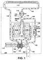
- FIG. 1is a block diagram of an internal combustion engine having a fluid mixer for mixing air with exhaust gas in accordance with the invention.
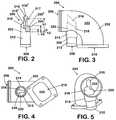
- FIG. 2is a rear view of the mixer in accordance with the invention.
- FIG. 3is a side view of the mixer assembly in accordance with the invention.
- FIG. 4is a bottom view of the mixer assembly in accordance with the invention.
- FIG. 5is a front perspective view of the mixer assembly in accordance with the invention.
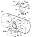
- FIG. 6is a top perspective view of an alternate embodiment of mixer in accordance with the invention.
- FIG. 7is a cut-away view of a mixer assembly in accordance with the invention.
- FIG. 8is a flowchart for a method of mixing air and exhaust gas for the internal combustion engine in accordance with the invention.
- the followingdescribes an apparatus for and method of operating an internal combustion engine having an exhaust gas recirculation (EGR) system associated therewith.
- the EGR system described hereinadvantageously includes a mixer that mixes exhaust gas with intake air to yield a mixture. The mixture is consumed by the engine by combustion within a plurality of cylinders.
- FIG. 1A block diagram of an engine 100 having an EGR system, as installed in a vehicle, is shown in FIG. 1 .
- the engine 100includes a turbocharger 102 having a turbine 104 and a compressor 106 .
- the compressor 106has an air inlet 108 connected to an air cleaner or filter 110 , and a charge air outlet 112 connected to a charge air cooler (CAC) 114 through CAC-hot passage 116 .
- the CAC 114has an outlet connected to an intake throttle valve (ITH) 118 through a CAC-cold passage 120 .
- the ITH 118is connected to an intake air conduit 122 that fluidly communicates with an intake system of the engine 100 , the intake system generally shown as 124 .
- Branches of the intake system 124are fluidly connected to each of a plurality of cylinders 126 that are included in a crankcase 128 of the engine 100 .
- Each of the plurality of cylinders 126 of the engineis connected to an exhaust system, generally shown as 130 .
- the exhaust system 130 of the engine 100is connected to an inlet 131 of the turbine 104 .
- An exhaust pipe 132is connected to an outlet of the turbine 104 .
- Other componentssuch as a muffler, catalyst, particulate filter, and so forth, may be connected to the exhaust pipe 132 and are not shown for the sake of simplicity.
- the engine 100has an EGR system, generally shown as 134 .
- the EGR system 134includes an EGR cooler 136 and an EGR valve 138 connected in a series configuration with each other for passage of exhaust gas therethrough.
- the EGR cooler 136fluidly communicates with the exhaust system 130 through an EGR gas supply passage 142 .
- the EGR valve 138is disposed in line with a cooled-EGR gas passage 148 that is in fluid communication with a junction 146 that is part of the intake air conduit 122 .
- a mixer 150is located at the junction 146 and fluidly communicates with and connects the cooled-EGR gas passage 148 with the intake air conduit 122 .
- airis filtered in the filter 110 and enters the compressor 106 through the inlet 108 where it is compressed. Compressed, or charged, air exits the compressor 106 through the outlet 112 and is cooled in the CAC 114 before passing through the ITH 118 .
- Air from the ITH 118is mixed with exhaust gas from the cooled-EGR gas passage 148 at the junction 146 through the mixer 150 to yield a mixture.
- the mixturepasses to the intake system 124 by continuing through the intake pipe 122 after the mixer 150 and enters the cylinders 126 . While in the cylinders 126 , the mixture is additionally mixed with fuel and combusts yielding useful work to the engine 100 , heat, and exhaust gas.
- the exhaust gas from each cylinder 126 following combustionis collected in the exhaust system 130 and routed to the turbine 104 . Exhaust gas passing through the turbine 104 yields work that is consumed by the compressor 106 .
- a portion of the exhaust gas in the exhaust system 130bypasses the turbine 104 and enters the EGR gas supply passage 142 .
- Exhaust gas entering the passage 142is exhaust gas that will be recirculated into the intake system 124 .
- the recirculated exhaust gasis cooled in the EGR cooler 136 , its amount is metered by the EGR valve 138 , and then the gas is routed to the junction 146 for mixing with the charge air exiting the ITH 118 in the mixer 150 .
- a mixer 200is shown in FIG. 2 through FIG. 5 .
- the mixer 200is inserted into an intake air conduit (shown as an elbow) 202 to form a mixer assembly 204 .
- the mixer assembly 204has an air inlet opening 206 , formed in the elbow 202 , an EGR gas opening 208 , formed in the mixer 200 , and a mixer outlet 210 that is formed in the elbow 202 .
- the mixer 200 and elbow 202 together in the mixer assembly 204perform a similar function to the mixer 150 shown in FIG. 1 , that is they both mix air and exhaust gas together.
- the mixer assembly 204can also provide functional interfaces for fluid connections to other engine components.
- the assembly 204is shown to include the elbow 202 to illustrate one configuration where the mixer 200 may be most advantageous to the operation of an engine.
- the elbow 202includes a 90-degree radius that typically would hinder formation of a homogeneous mixture.
- Use of the mixer 200advantageously provides a homogeneous mixture at the outlet 210 of air entering the assembly 204 through the air inlet opening 206 with exhaust gas entering the mixer 200 through the EGR gas opening 208 .
- the mixer 200includes an inlet port 212 that forms the EGR gas opening 208 and that protrudes from the elbow 202 .
- the inlet port 212is shown in a configuration that allows a hose (not shown) carrying exhaust gas to be connected thereto, but other configurations and modes of providing exhaust gas to a mixer are contemplated.
- the elbow 202forms a collar 214 that is arranged to accommodate the inlet port 212 portion of the mixer 200 therein, and provide support and sealing there-between.
- a dividing portion 217 of the mixer 200is generally “teardrop”-shaped, with a cornered end, however other configurations are contemplated.
- the “teardrop” or wingfoil-inspired shaperesults in less drag and less pressure drop for the air traveling around the mixer 200 .
- the dividing portion 217is disposed in an outer pipe 203 and defines a central passage 216 .
- the dividing portion 217also subdivides a first side-passage 218 and a second side-passage 220 on either side of the central passage 216 within the outer pipe 203 .
- the outlets 216 ′, 218 ′ and 220 ′ of the central passage 216 , the first side-passage 218 , and the second side-passage 220 , respectively,are located inside an internal passage volume 222 of the elbow 202 .
- the outlets 216 ′, 218 ′ and 220 ′are inclined such that the higher end of the outlet is nearer the inlet 206 of the intake air conduit 202 than a lower end of the outlet.
- Openings through which exhaust gas may exit the mixer 200 in each of the central, first-side, and second-side passages 216 , 218 and 220are advantageously positioned at different relative heights within the internal passage 222 of the elbow 202 .
- the central passage outlet 216 ′has an average height h 1 measured from a datum D located at the lowest point of the openings to the passages 216 , 218 , 220 , as shown in FIG. 2 .
- the average height of the outlet 218 ′is a height h 2 from the point where hi is measured from, with h 2 being less than h 1 .
- the outlet 220 ′has an average height h 3 measured from the same point h 1 and h 2 are measured from, with h 3 being less than h 1 and h 2 . Further, the maximum height of the outlet 216 ′ is greater than the maximum height of the outlet 218 ′, which is greater than the maximum height of the outlet 220 ′.
- outlets of the central passage 216 , the first side-passage 218 , and the second side-passage 220can be configured and arranged in different locations within the internal passage volume 222 . Further, the number, location and heights of the outlets within the conduit 202 can vary.
- FIG. 6 through FIG. 7A second embodiment of a mixer 600 disposed in an intake air conduit 700 to form a mixer assembly 603 is shown in FIG. 6 through FIG. 7 .
- the dividing portion 602includes a central portion 602 .
- the dividing portion 602has a “teardrop” or airfoil cross-sectional shape.
- the dividing portion 602is located within an outer pipe 604 .
- the dividing portion 602may be in contact with the outer pipe 604 along two diametrically opposite lines of contact 606 (only one visible), thus creating a first passage 608 and a second passage 610 between the dividing portion 602 and the outer pipe 604 .
- a third passage 612exists within the dividing portion 602 .
- a flow area of the outer pipe 604is segmented into three portions, the first passage 608 , the second passage 610 , and the third passage 612 .
- the average height of the outlets of the first passage 608 , the second passage 610 and the third passage 612are different from each other. That is, the outlets 608 ′, 610 ′ and 612 ′ of the first through third passages 608 , 610 , 612 are staggered in height.
- the outer pipe 604is cut to a length that is less than a length of the dividing portion 602 such that a segment of the dividing portion 602 protrudes past an end 614 of the outer pipe 604 .
- the end 614 of the outer pipe 604is stepped to create a first edge 616 for the first passage 608 that is different than a second edge 618 for the second passage 610 .
- Each of the first and second edges 616 and 618is substantially semi-circular and positioned along different lengths, or alternatively heights, along a length of the outer pipe 604 . In the embodiment shown, each of the first and second edges 616 and 618 is cut at an angle with respect to a circular cross-section of the circular outer pipe 604 .
- the mixer 600has a directional feature to direct flow passing therethrough, in that a portion 620 of a wall 622 of the outer pipe 604 is inclined inward along a region surrounding the first passage 608 such that a portion of a fluid flowing through the first passage 608 is directed toward the dividing portion 602 .
- FIG. 7A partial cross-sectional view of the mixing portion 600 as installed into an intake air conduit 700 of an internal combustion engine is shown in FIG. 7 .
- the intake air conduit 700has a circular cross section with a radius r and a centerline C, however other shapes are contemplated.
- the mixing portion 600 shown in this viewalso includes an EGR gas feed pipe 702 .
- the EGR gas feed pipe 702is connected to a source of exhaust gas (not shown) that may be, for example, an outlet port of an EGR valve or cooler (neither shown).
- airpasses through the intake air conduit 700 .
- the flow of air in the intake air conduit 700is denoted by dotted-lined-arrows, generally at 704 .
- the air flow 704enters the segment of the intake air conduit 700 at an inlet cross section 706 , passes over and around the mixer 600 , and exits the segment of the intake air conduit 700 at an outlet cross section 708 .
- a flow of exhaust gasreaches the mixer 600 through the EGR gas feed pipe 702 .
- the flow of exhaust gasis denoted by dashed-line-arrows, generally at 710 .
- the exhaust flow 710 in the EGR gas feed pipe 702is advantageously split into three sub-streams, with each sub-stream exiting the mixer 600 through the first passage 608 , the second passage 610 , and the third passage 612 . Even though the three sub-streams are described together, a flow rate of each depends on the outlet opening size of each of the first passage 608 , the second passage 610 , and the third passage 612 , which do not need to be equal. Therefore, each sub-stream exiting each flow passage can have a different flow rate than another stream.
- FIG. 8A flowchart for a method of mixing a flow of air with a flow of exhaust gas for an EGR system associated with an internal combustion engine is shown in FIG. 8 .
- a stream of exhaust gas from a high pressure or a low pressure location of an exhaust system of an enginepasses through an EGR valve at step 802 .
- the stream of exhaust gasmay be at a high or low pressure, and may optionally be cooled.
- the stream of exhaust gasis routed to a mixer assembly at step 804 . While passing through the mixer assembly, the stream of exhaust gas is separated into two or more sub-streams at step 806 . Each of the two or more sub-streams of exhaust gas is routed to one of two or more flow outlet passages at step 808 .
- Each of the two or more sub-streamsexits the mixer through its respective flow outlet passage at step 810 .
- Each of the two or more sub-streams exiting the mixeris mixed at different heights with a flow of air passing over and around the mixer in an intake air conduit at step 812 .
- a mixture formed by the flow of intake air and the two or more sub-streams of exhaust gasis routed to an internal combustion engine at step 814 , and the process is repeated as necessary for the operation of the internal combustion engine.
- the mixer assemblies 204 , 603mix the intake air with the exhaust gas under a variety of flow conditions, while keeping the pressure losses inside the conduit 202 , 700 to a minimum.
- the exhaust gasis distributed inside the conduit 202 , 700 by subdividing the flow with dividing portions into multiple passages, each passage having an outlet with a different range of height than other passages.
- the mixer assemblies 204 , 603can mix effectively over a wider range of fluid inlet velocities because the three release heights make it easier for exhaust fluid with low momentum to reach any desired height before it is released into the main air/fluid.
- the velocities of the streams of exhaust fluidcan be adjusted for maximizing distribution (and resultant mixing) and minimizing the pressure drop.
Landscapes
- Engineering & Computer Science (AREA)
- Chemical & Material Sciences (AREA)
- Chemical Kinetics & Catalysis (AREA)
- Combustion & Propulsion (AREA)
- Mechanical Engineering (AREA)
- General Engineering & Computer Science (AREA)
- Exhaust-Gas Circulating Devices (AREA)
- Accessories For Mixers (AREA)
Abstract
Description
Claims (15)
Priority Applications (8)
| Application Number | Priority Date | Filing Date | Title |
|---|---|---|---|
| US11/877,315US7740008B2 (en) | 2007-10-23 | 2007-10-23 | Multiple height fluid mixer and method of use |
| CA002641089ACA2641089A1 (en) | 2007-10-23 | 2008-10-15 | Multiple height fluid mixer and method of use |
| EP08018099AEP2053233B1 (en) | 2007-10-23 | 2008-10-15 | Multiple height fluid mixer and method of use |
| MX2008013290AMX2008013290A (en) | 2007-10-23 | 2008-10-16 | Multiple height fluid mixer and method of use. |
| KR1020080102507AKR20090041325A (en) | 2007-10-23 | 2008-10-20 | Multi-height fluid mixer and how to use it |
| CN2008101691567ACN101487426B (en) | 2007-10-23 | 2008-10-23 | Multiple height fluid mixer and method of use |
| JP2008272839AJP5233056B2 (en) | 2007-10-23 | 2008-10-23 | Multi-height fluid mixer and method of use |
| BRPI0804650-6ABRPI0804650A2 (en) | 2007-10-23 | 2008-10-23 | multipurpose fluid mixer and method for using it |
Applications Claiming Priority (1)
| Application Number | Priority Date | Filing Date | Title |
|---|---|---|---|
| US11/877,315US7740008B2 (en) | 2007-10-23 | 2007-10-23 | Multiple height fluid mixer and method of use |
Publications (2)
| Publication Number | Publication Date |
|---|---|
| US20090101123A1 US20090101123A1 (en) | 2009-04-23 |
| US7740008B2true US7740008B2 (en) | 2010-06-22 |
Family
ID=40225460
Family Applications (1)
| Application Number | Title | Priority Date | Filing Date |
|---|---|---|---|
| US11/877,315Active2028-07-22US7740008B2 (en) | 2007-10-23 | 2007-10-23 | Multiple height fluid mixer and method of use |
Country Status (8)
| Country | Link |
|---|---|
| US (1) | US7740008B2 (en) |
| EP (1) | EP2053233B1 (en) |
| JP (1) | JP5233056B2 (en) |
| KR (1) | KR20090041325A (en) |
| CN (1) | CN101487426B (en) |
| BR (1) | BRPI0804650A2 (en) |
| CA (1) | CA2641089A1 (en) |
| MX (1) | MX2008013290A (en) |
Cited By (8)
| Publication number | Priority date | Publication date | Assignee | Title |
|---|---|---|---|---|
| US20070150804A1 (en)* | 2000-04-18 | 2007-06-28 | Kforce Inc. | Method, system, and computer program product for propagating remotely configurable posters of host site content |
| US20090094541A1 (en)* | 2000-04-25 | 2009-04-09 | Foulger Michael G | Methods, Systems and Computer Program Products for Scheduling Executions of Programs |
| US20110061634A1 (en)* | 2008-01-24 | 2011-03-17 | Mack Trucks, Inc. | Exhaust gas recirculation mixer device |
| US20160169164A1 (en)* | 2013-07-23 | 2016-06-16 | Mahindra & Mahindra Ltd. | Naturally aspirated common rail diesel engine meeting ultra low pm emission by passive exhaust after treatment |
| US9926891B2 (en) | 2015-11-18 | 2018-03-27 | General Electric Company | System and method of exhaust gas recirculation |
| WO2020016419A1 (en)* | 2018-07-20 | 2020-01-23 | Eaton Intelligent Power Limited | Egr ejector system |
| WO2020150054A1 (en) | 2019-01-16 | 2020-07-23 | Qorvo Us, Inc. | Single-wire bus, subus, slave circuit and related apparatus |
| US11319909B1 (en)* | 2020-12-08 | 2022-05-03 | Ford Global Technologies, Llc | Exhaust gas recirculation mixer |
Families Citing this family (12)
| Publication number | Priority date | Publication date | Assignee | Title |
|---|---|---|---|---|
| FR2945963A1 (en)* | 2009-05-27 | 2010-12-03 | Mark Iv Systemes Moteurs Sa | DEVICE FOR INJECTING AND DIFFUSING GASEOUS FLUID AND ADMISSION DISTRIBUTION INTEGRATING SUCH A DEVICE |
| US8430083B2 (en)* | 2009-10-20 | 2013-04-30 | Harvey Holdings, Llc | Mixer for use in an exhaust gas recirculation system and method for assembly of the same |
| KR101682477B1 (en)* | 2010-02-17 | 2016-12-05 | 보르그워너 인코퍼레이티드 | Turbocharger |
| KR101227177B1 (en)* | 2010-10-11 | 2013-01-28 | 한국기계연구원 | Device for supplying Recirculation Exhaust Gas in diesel engine system and method thereof |
| US8915235B2 (en)* | 2011-06-28 | 2014-12-23 | Caterpillar Inc. | Mixing system for engine with exhaust gas recirculation |
| WO2013163054A1 (en) | 2012-04-25 | 2013-10-31 | International Engine Intellectual Property Company, Llc | Engine braking |
| JP5972180B2 (en)* | 2013-01-15 | 2016-08-17 | ヤンマー株式会社 | engine |
| US9932875B2 (en)* | 2016-03-02 | 2018-04-03 | Ford Global Technologies, Llc | Mixer for mixing exhaust gas |
| CN107261873B (en)* | 2017-06-23 | 2023-06-02 | 东风商用车有限公司 | Pipeline fluid mixer structure |
| CN107252640B (en)* | 2017-06-23 | 2023-06-27 | 东风商用车有限公司 | Pipeline fluid mixer assembly |
| CN111022222B (en)* | 2019-11-28 | 2021-10-08 | 一汽解放汽车有限公司 | Adjustable EGR hybrid system |
| JP2025082365A (en)* | 2023-11-17 | 2025-05-29 | ヤンマーホールディングス株式会社 | Exhaust emission control device |
Citations (9)
| Publication number | Priority date | Publication date | Assignee | Title |
|---|---|---|---|---|
| US5196148A (en)* | 1992-02-18 | 1993-03-23 | Nigrelli Systems Inc. | Aerator |
| US5207714A (en)* | 1991-01-25 | 1993-05-04 | Aisin Seiki Kabushiki Kaisha | Exhausted gas recycle device |
| US5322043A (en)* | 1992-08-05 | 1994-06-21 | Shriner Robert D | Spiral spin charge or sheathing system |
| US6425382B1 (en) | 2001-01-09 | 2002-07-30 | Cummins Engine Company, Inc. | Air-exhaust mixer assembly |
| US6427671B1 (en)* | 2000-07-17 | 2002-08-06 | Caterpillar Inc. | Exhaust gas recirculation mixer apparatus and method |
| US6513508B2 (en)* | 1999-07-15 | 2003-02-04 | Filterwerk Mann & Hummel Gmbh | Fluid feed duct for a hot fluid in a hollow structure |
| US6637731B2 (en)* | 2001-05-03 | 2003-10-28 | Tomco2 Equipment Company | Diffuser for use in a carbonic acid control system |
| US20040112345A1 (en)* | 2001-03-02 | 2004-06-17 | Volvo Lastvagnar Ab | Apparatus for supply of recirculated exhaust gas |
| US6810867B2 (en)* | 2000-02-17 | 2004-11-02 | Daimlerchrysler Ag | Exhaust gas recirculation device |
Family Cites Families (11)
| Publication number | Priority date | Publication date | Assignee | Title |
|---|---|---|---|---|
| JPS5476421U (en)* | 1977-11-08 | 1979-05-31 | ||
| JPS5848972U (en)* | 1981-09-29 | 1983-04-02 | 日産自動車株式会社 | Diesel engine intake passage device |
| JPS63319030A (en)* | 1987-06-22 | 1988-12-27 | Reika Kogyo Kk | Ejector |
| SE500071C2 (en)* | 1992-06-25 | 1994-04-11 | Vattenfall Utveckling Ab | Device for mixing two fluids, in particular liquids of different temperature |
| JP2000054915A (en)* | 1998-08-10 | 2000-02-22 | Isuzu Motors Ltd | Egr device |
| JP3923665B2 (en)* | 1998-09-22 | 2007-06-06 | 日野自動車株式会社 | EGR device for supercharged engine |
| DE102004025254A1 (en)* | 2004-05-22 | 2005-12-08 | Daimlerchrysler Ag | Exhaust gas recycling type diesel engine for motor vehicle has exhaust reconducting mechanism having discharge opening provided with turbulence production arrangement |
| JP2006152843A (en)* | 2004-11-26 | 2006-06-15 | Sanwa Seiki Co Ltd | Exhaust gas recirculation device |
| DE102005020484A1 (en)* | 2005-04-29 | 2006-11-02 | Mahle International Gmbh | Exhaust gas recirculation device for internal combustion engine, has exhaust gas recirculation valve for controlling exhaust gas recirculation line and comprising actuating device for axially adjusting sleeve relative to fresh-air duct |
| JP5006559B2 (en)* | 2006-03-20 | 2012-08-22 | 日産自動車株式会社 | EGR device for multi-cylinder internal combustion engine |
| DE102006017004B3 (en)* | 2006-04-11 | 2007-10-25 | Airbus Deutschland Gmbh | Device for mixing fresh air and heating air and use thereof in a ventilation system of an aircraft |
- 2007
- 2007-10-23USUS11/877,315patent/US7740008B2/enactiveActive
- 2008
- 2008-10-15EPEP08018099Apatent/EP2053233B1/ennot_activeCeased
- 2008-10-15CACA002641089Apatent/CA2641089A1/ennot_activeAbandoned
- 2008-10-16MXMX2008013290Apatent/MX2008013290A/enactiveIP Right Grant
- 2008-10-20KRKR1020080102507Apatent/KR20090041325A/ennot_activeWithdrawn
- 2008-10-23BRBRPI0804650-6Apatent/BRPI0804650A2/enactiveSearch and Examination
- 2008-10-23CNCN2008101691567Apatent/CN101487426B/enactiveActive
- 2008-10-23JPJP2008272839Apatent/JP5233056B2/ennot_activeExpired - Fee Related
Patent Citations (9)
| Publication number | Priority date | Publication date | Assignee | Title |
|---|---|---|---|---|
| US5207714A (en)* | 1991-01-25 | 1993-05-04 | Aisin Seiki Kabushiki Kaisha | Exhausted gas recycle device |
| US5196148A (en)* | 1992-02-18 | 1993-03-23 | Nigrelli Systems Inc. | Aerator |
| US5322043A (en)* | 1992-08-05 | 1994-06-21 | Shriner Robert D | Spiral spin charge or sheathing system |
| US6513508B2 (en)* | 1999-07-15 | 2003-02-04 | Filterwerk Mann & Hummel Gmbh | Fluid feed duct for a hot fluid in a hollow structure |
| US6810867B2 (en)* | 2000-02-17 | 2004-11-02 | Daimlerchrysler Ag | Exhaust gas recirculation device |
| US6427671B1 (en)* | 2000-07-17 | 2002-08-06 | Caterpillar Inc. | Exhaust gas recirculation mixer apparatus and method |
| US6425382B1 (en) | 2001-01-09 | 2002-07-30 | Cummins Engine Company, Inc. | Air-exhaust mixer assembly |
| US20040112345A1 (en)* | 2001-03-02 | 2004-06-17 | Volvo Lastvagnar Ab | Apparatus for supply of recirculated exhaust gas |
| US6637731B2 (en)* | 2001-05-03 | 2003-10-28 | Tomco2 Equipment Company | Diffuser for use in a carbonic acid control system |
Cited By (12)
| Publication number | Priority date | Publication date | Assignee | Title |
|---|---|---|---|---|
| US20070150804A1 (en)* | 2000-04-18 | 2007-06-28 | Kforce Inc. | Method, system, and computer program product for propagating remotely configurable posters of host site content |
| US20070204219A1 (en)* | 2000-04-18 | 2007-08-30 | Foulger Michael G | Method, system, and computer program product for propagating remotely configurable posters of host site content |
| US8266242B2 (en) | 2000-04-18 | 2012-09-11 | Archeron Limited L.L.C. | Method, system, and computer program product for propagating remotely configurable posters of host site content |
| US20090094541A1 (en)* | 2000-04-25 | 2009-04-09 | Foulger Michael G | Methods, Systems and Computer Program Products for Scheduling Executions of Programs |
| US20110061634A1 (en)* | 2008-01-24 | 2011-03-17 | Mack Trucks, Inc. | Exhaust gas recirculation mixer device |
| US9488098B2 (en)* | 2008-01-24 | 2016-11-08 | Mack Trucks, Inc. | Exhaust gas recirculation mixer device |
| US20160169164A1 (en)* | 2013-07-23 | 2016-06-16 | Mahindra & Mahindra Ltd. | Naturally aspirated common rail diesel engine meeting ultra low pm emission by passive exhaust after treatment |
| US9926891B2 (en) | 2015-11-18 | 2018-03-27 | General Electric Company | System and method of exhaust gas recirculation |
| WO2020016419A1 (en)* | 2018-07-20 | 2020-01-23 | Eaton Intelligent Power Limited | Egr ejector system |
| CN112585343A (en)* | 2018-07-20 | 2021-03-30 | 伊顿智能动力有限公司 | EGR injector system |
| WO2020150054A1 (en) | 2019-01-16 | 2020-07-23 | Qorvo Us, Inc. | Single-wire bus, subus, slave circuit and related apparatus |
| US11319909B1 (en)* | 2020-12-08 | 2022-05-03 | Ford Global Technologies, Llc | Exhaust gas recirculation mixer |
Also Published As
| Publication number | Publication date |
|---|---|
| US20090101123A1 (en) | 2009-04-23 |
| JP5233056B2 (en) | 2013-07-10 |
| CA2641089A1 (en) | 2009-04-23 |
| EP2053233A3 (en) | 2010-03-10 |
| CN101487426B (en) | 2012-10-24 |
| KR20090041325A (en) | 2009-04-28 |
| MX2008013290A (en) | 2009-05-12 |
| BRPI0804650A2 (en) | 2009-06-30 |
| EP2053233B1 (en) | 2011-06-01 |
| CN101487426A (en) | 2009-07-22 |
| JP2009103133A (en) | 2009-05-14 |
| EP2053233A2 (en) | 2009-04-29 |
Similar Documents
| Publication | Publication Date | Title |
|---|---|---|
| US7740008B2 (en) | Multiple height fluid mixer and method of use | |
| US9080536B2 (en) | Systems and methods for exhaust gas recirculation | |
| US7032578B2 (en) | Venturi mixing system for exhaust gas recirculation (EGR) | |
| US7140357B2 (en) | Vortex mixing system for exhaust gas recirculation (EGR) | |
| KR101947829B1 (en) | Apparatus and method for exhaust gas aftertreatment | |
| US7028680B2 (en) | Two stage mixing system for exhaust gas recirculation (EGR) | |
| JP2004519576A (en) | Recirculation exhaust gas supply device | |
| CN100425820C (en) | Two-stroke large diesel engine | |
| CN101970830A (en) | Exhaust gas recirculation mixer device | |
| US8967127B2 (en) | Intake apparatus for internal combustion engine | |
| US5535717A (en) | Fluid distribution method in dual intake manifolds | |
| EP0857870A2 (en) | Internal combustion diesel engine with exhaust gases re-circulation, provided with a device for mixing the re-circulation gases | |
| US5492093A (en) | Fluid distributing in dual intake manifolds | |
| US9938934B2 (en) | Exhaust gas recirculation | |
| EP2565414B1 (en) | Exhaust manifold | |
| WO2019130760A1 (en) | Multi-cylinder engine intake structure | |
| JP6700823B2 (en) | Gas recirculation device | |
| US10815940B2 (en) | Intake manifold with integrated mixer | |
| SE536919C2 (en) | Device for recirculating exhaust gases in an internal combustion engine | |
| US9228539B2 (en) | Exhaust gas recirculation mixer | |
| US20140238362A1 (en) | Mixing chamber of exhaust gas recirculation system | |
| JP2000008970A (en) | Exhaust gas recirculation system for internal combustion engine | |
| US20240050882A1 (en) | Gas-liquid separator | |
| JP3383337B2 (en) | Intake collector | |
| JP6965835B2 (en) | Engine intake system |
Legal Events
| Date | Code | Title | Description |
|---|---|---|---|
| AS | Assignment | Owner name:INTERNATIONAL ENGINE INTELLECTUAL PROPERTY COMPANY Free format text:ASSIGNMENT OF ASSIGNORS INTEREST;ASSIGNORS:BROGDON, JAMES W.;RIDLEY, IAIN V.;BEATTY, SCOTT A.;SIGNING DATES FROM 20071101 TO 20080326;REEL/FRAME:020712/0464 Owner name:INTERNATIONAL ENGINE INTELLECTUAL PROPERTY COMPANY Free format text:ASSIGNMENT OF ASSIGNORS INTEREST;ASSIGNORS:BROGDON, JAMES W.;RIDLEY, IAIN V.;BEATTY, SCOTT A.;REEL/FRAME:020712/0464;SIGNING DATES FROM 20071101 TO 20080326 | |
| STCF | Information on status: patent grant | Free format text:PATENTED CASE | |
| AS | Assignment | Owner name:JPMORGAN CHASE BANK, N.A., AS COLLATERAL AGENT, NE Free format text:SECURITY AGREEMENT;ASSIGNORS:INTERNATIONAL ENGINE INTELLECTUAL PROPERTY COMPANY, LLC;INTERNATIONAL TRUCK INTELLECTUAL PROPERTY COMPANY, LLC;NAVISTAR INTERNATIONAL CORPORATION;AND OTHERS;REEL/FRAME:028944/0730 Effective date:20120817 | |
| FPAY | Fee payment | Year of fee payment:4 | |
| AS | Assignment | Owner name:JPMORGAN CHASE BANK N.A., AS COLLATERAL AGENT, NEW Free format text:SECURITY AGREEMENT;ASSIGNORS:NAVISTAR INTERNATIONAL CORPORATION;INTERNATIONAL TRUCK INTELLECTUAL PROPERTY COMPANY, LLC;INTERNATIONAL ENGINE INTELLECTUAL PROPERTY COMPANY, LLC;REEL/FRAME:036616/0243 Effective date:20150807 | |
| AS | Assignment | Owner name:JPMORGAN CHASE BANK, N.A., AS COLLATERAL AGENT, NEW YORK Free format text:SECURITY INTEREST;ASSIGNORS:NAVISTAR INTERNATIONAL CORPORATION;NAVISTAR, INC.;REEL/FRAME:044418/0310 Effective date:20171106 Owner name:INTERNATIONAL TRUCK INTELLECTUAL PROPERTY COMPANY, Free format text:RELEASE BY SECURED PARTY;ASSIGNOR:JPMORGAN CHASE BANK, N.A., AS COLLATERAL AGENT;REEL/FRAME:044780/0456 Effective date:20171106 Owner name:INTERNATIONAL ENGINE INTELLECTUAL PROPERTY COMPANY Free format text:RELEASE BY SECURED PARTY;ASSIGNOR:JPMORGAN CHASE BANK, N.A., AS COLLATERAL AGENT;REEL/FRAME:044780/0456 Effective date:20171106 Owner name:NAVISTAR INTERNATIONAL CORPORATION, ILLINOIS Free format text:RELEASE BY SECURED PARTY;ASSIGNOR:JPMORGAN CHASE BANK, N.A., AS COLLATERAL AGENT;REEL/FRAME:044780/0456 Effective date:20171106 Owner name:NAVISTAR INTERNATIONAL CORPORATION, ILLINOIS Free format text:RELEASE BY SECURED PARTY;ASSIGNOR:JPMORGAN CHASE BANK, N.A., AS COLLATERAL AGENT;REEL/FRAME:044416/0867 Effective date:20171106 Owner name:INTERNATIONAL ENGINE INTELLECTUAL PROPERTY COMPANY Free format text:RELEASE BY SECURED PARTY;ASSIGNOR:JPMORGAN CHASE BANK, N.A., AS COLLATERAL AGENT;REEL/FRAME:044416/0867 Effective date:20171106 Owner name:JPMORGAN CHASE BANK, N.A., AS COLLATERAL AGENT, NE Free format text:SECURITY INTEREST;ASSIGNORS:NAVISTAR INTERNATIONAL CORPORATION;NAVISTAR, INC.;REEL/FRAME:044418/0310 Effective date:20171106 Owner name:INTERNATIONAL TRUCK INTELLECTUAL PROPERTY COMPANY, Free format text:RELEASE BY SECURED PARTY;ASSIGNOR:JPMORGAN CHASE BANK, N.A., AS COLLATERAL AGENT;REEL/FRAME:044416/0867 Effective date:20171106 Owner name:NAVISTAR, INC., ILLINOIS Free format text:RELEASE BY SECURED PARTY;ASSIGNOR:JPMORGAN CHASE BANK, N.A., AS COLLATERAL AGENT;REEL/FRAME:044416/0867 Effective date:20171106 | |
| MAFP | Maintenance fee payment | Free format text:PAYMENT OF MAINTENANCE FEE, 8TH YEAR, LARGE ENTITY (ORIGINAL EVENT CODE: M1552) Year of fee payment:8 | |
| AS | Assignment | Owner name:JPMORGAN CHASE BANK, N.A., AS ADMINISTRATIVE AGENT, NEW YORK Free format text:SECURITY INTEREST;ASSIGNORS:INTERNATIONAL TRUCK INTELLECTUAL PROPERTY COMPANY, LLC;INTERNATIONAL ENGINE INTELLECTUAL PROPERTY COMPANY, LLC;NAVISTAR, INC. (F/K/A INTERNATIONAL TRUCK AND ENGINE CORPORATION);REEL/FRAME:052483/0742 Effective date:20200423 | |
| AS | Assignment | Owner name:THE BANK OF NEW YORK MELLON TRUST COMPANY, N.A., AS COLLATERAL AGENT, ILLINOIS Free format text:SECURITY INTEREST;ASSIGNORS:NAVISTAR INTERNATIONAL CORPORATION;INTERNATIONAL ENGINE INTELLECTUAL PROPERTY COMPANY, LLC;INTERNATIONAL TRUCK INTELLECTUAL PROPERTY COMPANY, LLC;AND OTHERS;REEL/FRAME:053545/0443 Effective date:20200427 Owner name:JPMORGAN CHASE BANK, N.A., AS ADMINISTRATIVE AGENT, NEW YORK Free format text:CORRECTIVE ASSIGNMENT TO CORRECT THE CONVEYING PARTY DATA PREVIOUSLY RECORDED AT REEL: 052483 FRAME: 0742. ASSIGNOR(S) HEREBY CONFIRMS THE SECURITY INTEREST.;ASSIGNORS:NAVISTAR INTERNATIONAL CORPORATION;INTERNATIONAL ENGINE INTELLECTUAL PROPERTY COMPANY, LLC;INTERNATIONAL TRUCK INTELLECTUAL PROPERTY COMPANY, LLC;AND OTHERS;REEL/FRAME:053457/0001 Effective date:20200423 | |
| AS | Assignment | Owner name:INTERNATIONAL TRUCK INTELLECTUAL PROPERTY COMPANY, LLC, ILLINOIS Free format text:RELEASE BY SECURED PARTY;ASSIGNOR:JPMORGAN CHASE BANK, N.A., AS ADMINISTRATIVE AGENT;REEL/FRAME:056757/0136 Effective date:20210701 Owner name:NAVISTAR, INC. (F/KA/ INTERNATIONAL TRUCK AND ENGINE CORPORATION), ILLINOIS Free format text:RELEASE BY SECURED PARTY;ASSIGNOR:JPMORGAN CHASE BANK, N.A., AS ADMINISTRATIVE AGENT;REEL/FRAME:056757/0136 Effective date:20210701 Owner name:INTERNATIONAL ENGINE INTELLECTUAL PROPERTY COMPANY, LLC, ILLINOIS Free format text:RELEASE BY SECURED PARTY;ASSIGNOR:JPMORGAN CHASE BANK, N.A., AS ADMINISTRATIVE AGENT;REEL/FRAME:056757/0136 Effective date:20210701 | |
| AS | Assignment | Owner name:NAVISTAR, INC., ILLINOIS Free format text:RELEASE OF SECURITY INTEREST RECORDED AT REEL/FRAME 53545/443;ASSIGNOR:THE BANK OF NEW YORK MELLON TRUST COMPANY, N.A.;REEL/FRAME:057441/0404 Effective date:20210701 Owner name:INTERNATIONAL ENGINE INTELLECTUAL PROPERTY COMPANY, LLC, ILLINOIS Free format text:RELEASE OF SECURITY INTEREST RECORDED AT REEL/FRAME 53545/443;ASSIGNOR:THE BANK OF NEW YORK MELLON TRUST COMPANY, N.A.;REEL/FRAME:057441/0404 Effective date:20210701 Owner name:INTERNATIONAL TRUCK INTELLECTUAL PROPERTY COMPANY, LLC, ILLINOIS Free format text:RELEASE OF SECURITY INTEREST RECORDED AT REEL/FRAME 53545/443;ASSIGNOR:THE BANK OF NEW YORK MELLON TRUST COMPANY, N.A.;REEL/FRAME:057441/0404 Effective date:20210701 Owner name:NAVISTAR INTERNATIONAL CORPORATION, ILLINOIS Free format text:RELEASE OF SECURITY INTEREST RECORDED AT REEL/FRAME 53545/443;ASSIGNOR:THE BANK OF NEW YORK MELLON TRUST COMPANY, N.A.;REEL/FRAME:057441/0404 Effective date:20210701 | |
| MAFP | Maintenance fee payment | Free format text:PAYMENT OF MAINTENANCE FEE, 12TH YEAR, LARGE ENTITY (ORIGINAL EVENT CODE: M1553); ENTITY STATUS OF PATENT OWNER: LARGE ENTITY Year of fee payment:12 |