US7739718B1 - System and method for automatically sensing the state of a video display device - Google Patents
System and method for automatically sensing the state of a video display deviceDownload PDFInfo
- Publication number
- US7739718B1 US7739718B1US10/261,548US26154802AUS7739718B1US 7739718 B1US7739718 B1US 7739718B1US 26154802 AUS26154802 AUS 26154802AUS 7739718 B1US7739718 B1US 7739718B1
- Authority
- US
- United States
- Prior art keywords
- node
- multimedia device
- multimedia
- operational state
- power usage
- Prior art date
- Legal status (The legal status is an assumption and is not a legal conclusion. Google has not performed a legal analysis and makes no representation as to the accuracy of the status listed.)
- Active, expires
Links
Images


Classifications
- H—ELECTRICITY
- H04—ELECTRIC COMMUNICATION TECHNIQUE
- H04L—TRANSMISSION OF DIGITAL INFORMATION, e.g. TELEGRAPHIC COMMUNICATION
- H04L12/00—Data switching networks
- H04L12/28—Data switching networks characterised by path configuration, e.g. LAN [Local Area Networks] or WAN [Wide Area Networks]
- H04L12/2803—Home automation networks
- H04L12/2807—Exchanging configuration information on appliance services in a home automation network
- H04L12/2809—Exchanging configuration information on appliance services in a home automation network indicating that an appliance service is present in a home automation network
- H—ELECTRICITY
- H04—ELECTRIC COMMUNICATION TECHNIQUE
- H04L—TRANSMISSION OF DIGITAL INFORMATION, e.g. TELEGRAPHIC COMMUNICATION
- H04L12/00—Data switching networks
- H04L12/28—Data switching networks characterised by path configuration, e.g. LAN [Local Area Networks] or WAN [Wide Area Networks]
- H04L12/2803—Home automation networks
- H04L12/2816—Controlling appliance services of a home automation network by calling their functionalities
- H04L12/2821—Avoiding conflicts related to the use of home appliances
- H—ELECTRICITY
- H04—ELECTRIC COMMUNICATION TECHNIQUE
- H04L—TRANSMISSION OF DIGITAL INFORMATION, e.g. TELEGRAPHIC COMMUNICATION
- H04L65/00—Network arrangements, protocols or services for supporting real-time applications in data packet communication
- H04L65/1066—Session management
- H04L65/1083—In-session procedures
- H04L65/1094—Inter-user-equipment sessions transfer or sharing
- H—ELECTRICITY
- H04—ELECTRIC COMMUNICATION TECHNIQUE
- H04L—TRANSMISSION OF DIGITAL INFORMATION, e.g. TELEGRAPHIC COMMUNICATION
- H04L65/00—Network arrangements, protocols or services for supporting real-time applications in data packet communication
- H04L65/80—Responding to QoS
- H—ELECTRICITY
- H04—ELECTRIC COMMUNICATION TECHNIQUE
- H04N—PICTORIAL COMMUNICATION, e.g. TELEVISION
- H04N21/00—Selective content distribution, e.g. interactive television or video on demand [VOD]
- H04N21/40—Client devices specifically adapted for the reception of or interaction with content, e.g. set-top-box [STB]; Operations thereof
- H04N21/43—Processing of content or additional data, e.g. demultiplexing additional data from a digital video stream; Elementary client operations, e.g. monitoring of home network or synchronising decoder's clock; Client middleware
- H04N21/436—Interfacing a local distribution network, e.g. communicating with another STB or one or more peripheral devices inside the home
- H04N21/43615—Interfacing a Home Network, e.g. for connecting the client to a plurality of peripherals
Definitions
- This inventionrelates generally to the field of multimedia distribution. More particularly, this invention relates to a system and method for automatically sensing the state of a video display device.
- a cable or satellite receiverWhen subscribing to a cable or satellite television service, a cable or satellite receiver is typically required for each television set within the user's home.
- set-top boxesare costly to manufacture, particularly those equipped with mass storage devices for storing television programming (commonly known as “Personal Video Recorders” or “PVRs”).
- PVRsPersonal Video Recorders
- requiring an individual set-top box for each television setis an unreasonable solution in many cases (e.g., particularly if the user has numerous television sets).
- the assignee of the present applicationhas developed a multimedia system and associated technologies for distributing multimedia content (e.g., cable/satellite television programming) from a primary receiver device to a plurality of secondary devices.
- the primary receiver deviceis a relatively high-powered device (i.e., relative to the secondary devices), capable of concurrently processing multiple satellite/cable channels and distributing those channels to the secondary devices. Because most of the signal processing load is handled by the primary receiver device, the secondary devices can be manufactured relatively inexpensively, resulting in a more efficient solution for the end user and the cable/satellite service provider.
- a media server 110e.g., a “set-top box” or game console
- a processore.g., a central repository for decoding and storing multimedia content and distributing the multimedia content to a plurality of nodes.
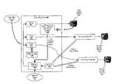
- the media server 110processes multimedia content from Internet communication channels 120 (e.g., DSL, cable modem), broadcast communication channels 130 (e.g., digital/analog cable, satellite), and/or Public Switched Telephone Network (“PSTN”) communication channels 170 (i.e., standard telephone) to provide a stable, real-time home media network 140 for a plurality of network devices 150 - 151 , 160 - 166 .
- Internet communication channels 120e.g., DSL, cable modem
- broadcast communication channels 130e.g., digital/analog cable, satellite
- PSTNPublic Switched Telephone Network
- FIG. 1illustrates one embodiment of a multimedia distribution system including a media server.
- FIG. 2illustrates the wiring of a typical home coaxial network.
- FIG. 3illustrates an exemplary bandwidth allocation employed over a local network according to one embodiment.
- FIG. 4illustrates an originating node (e.g., a media server) communicating with a plurality of receiving nodes according to one embodiment of the invention.
- originating nodee.g., a media server
- FIG. 5illustrates one embodiment of a multimedia distribution system having a limited number of tuners.
- FIG. 6illustrates one embodiment of a receiving node which includes power detection circuitry and logic.
- FIG. 7illustrates an originating node which includes resource allocation logic according to one embodiment of the invention.
- FIG. 8illustrates a current sensor employed in one embodiment of the invention.
- FIG. 9illustrates power detection circuitry employed in one embodiment of the invention.
- FIGS. 10 a - billustrate signals generated according to one embodiment of the invention.
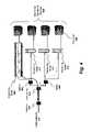
- a signal reflector device 401communicatively coupled between the cable network 110 and a root splitter 402 , reflects signals transmitted from the nodes 400 , 410 - 412 of the home network back towards the nodes. For example, a signal transmitted from the originating node 400 illustrated in FIG. 4 will initially pass through splitter 403 followed by the root splitter 402 before reaching the reflector device 401 . The reflector device 401 will then reflect the signal back to one of the receiving nodes (e.g., through the root splitter 402 and splitter 404 to reach receiving node 412 ).
- each of the receiving nodes 410 - 412may be configured to receive signals transmitted from the originating node 400 at a specified carrier frequency.
- the originating node 400may transmit data packets containing addresses of specified receiving nodes (e.g., such as TCP/IP packets).
- TCP/IP packetse.g., TCP/IP packets
- upstream and downstreamas used herein is based on the direction in which cable signals are transmitted from the external cable network 110 (or, rather, the direction in which cable signals would be transmitted if the user were a cable subscriber).
- the external cable network 110is “upstream” relative to the local cable network 110 illustrated in FIG. 4 .
- the root splitter 402is located “upstream” relative to splitters 403 and 404 because a signal transmitted from the external cable network would pass through the root splitter before reaching splitters 402 and 403 .
- the originating node 400is comprised of the hardware/software architecture of the “media server” described in the pending application entitled MULTIMEDIA AND COMPUTING SYSTEM mentioned above.
- the originating node 400concurrently stores and processes content from multiple cable and/or satellite channels as well as other types of multimedia content (e.g., MP-3 audio content ripped from compact disks, Internet content, . . . etc).
- the originating node 400may concurrently provide live and/or pre-recorded programs to each of the receiving nodes 410 - 412 (illustrated as distributed multimedia nodes 250 - 251 in FIG.
- the buffered and/or pre-recorded program contentmay be stored on the originating node's 400 's mass storage device 330 .
- the originating node 400may also be comprised of a completely different architecture than that described in the MULTIMEDIA AND COMPUTING SYSTEM application.
- the originating node 400may simply be a DVD player, an MP3 player, a cable/satellite receiver, or an off-air antenna (i.e., equipped with a transmitter for transmitting to the receiving nodes 410 - 412 ).
- the originating node 400does not necessarily need a hard drive to comply with the underlying principles of the invention.
- each of the receiving nodes 410 - 412is configured to transmit certain types of data back to the originating node 400 via the reflector device 401 .
- control datamay be transmitted to identify to the originating node 400 which channels, recorded program content and/or other data the originating node 400 should transmit to each of the receiving nodes 410 - 412 . Examples of these control functions and other information transmitted from the receiving nodes 410 - 412 are described in greater detail below.
- state information of each video display device coupled to each receiving node 410 - 412may also be transmitted through the control channels to the originating node 400 .
- the signal reflector device 401down-converts the frequencies at which signals are reflected so as to circumvent any canceling action of the various splitters 402 - 404 .
- the first 0-1000 MHz of spectrummay be reserved for incoming cable channels. This 1000 MHz limit may vary from operator to operator depending on the frequency plan for the particular operator in question.
- the attenuation characteristics of most community cable plantsare such that most operators typically leave unutilized spectrum above 750 MHz, 860 MHz or 1000 MHz depending on their particular plant configuration.
- a “transmit” block of spectrum 431 and a “receive” block of spectrum 432may be defined for signals transmitted towards and reflected away from the reflector device 401 , respectively, which do not interfere with the cable services being provided below the cable operator cutoff frequency.
- the transmit block 431is defined to be between 1200 MHz and 1400 MHz and the receive block is defined to be between 1000 MHz and 1200 MHz.
- the particular manner in which bandwidth is allocatedis not pertinent to the underlying principles of the invention.
- the transmit block 431 and receive block 432 illustrated in FIG. 4may be reversed (i.e., signals may be transmitted at a relatively lower frequency than at which they are received).
- the blocksmay also be widened or narrowed, depending on the particular bandwidth requirements of the system.
- the splitters 402 and 403 leading to the reflector device 401may be replaced with devices that attenuate the signal less along the reverse path (e.g., directional couplers).
- a separate cablemay also be run directly from the originating node 400 back to either the reflector device 401 and/or to the root splitter 402 .
- the signal transmission powermay be increased at the originating node 400 as required to provide an adequate signal at the reflector device 401 .
- the reflector device 401 shown in FIG. 4is positioned upstream relative to the root splitter 402 (i.e., between the root splitter 402 and the external cable network 110 ), the reflector device 401 may also be positioned downstream of the root splitter 402 while still complying with the principles of the invention (i.e., between the root splitter 402 and splitters 403 and 404 ).
- the originating node 400may concurrently supply multimedia content to a plurality of different receiving nodes 410 - 412 and a mass storage device 330 .
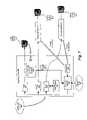
- the originating node 400may only be capable of processing a limited number of multimedia streams at a time. For example, as illustrated in FIG. 5 , if the originating node 400 is only equipped with three standard cable/satellite tuners 501 - 503 , then it may only be capable of concurrently distributing three cable/satellite channels.
- one tuner 501is allocated to the local display device 510 (i.e., the device coupled directly to the originating node, as in a typical set-top box configuration), one tuner is allocated to one of the remote receiving nodes 411 and one tuner is allocated to the mass storage device 503 (e.g., to record a user-specified program), then the originating node 400 is unable to distribute an additional channel to the remaining receiving nodes 410 .
- the originating node 400allocates all three tuners 501 - 503 to the local display device 510 and the two receiving nodes 410 and 411 , then it is unable to concurrently record a cable/satellite program to the mass storage device 330 . It is also unable to distribute an additional channel to any remaining receiving nodes (not shown).
- one embodiment of the inventionintelligently allocates tuners to local and remote display devices and mass storage devices based on whether these devices are being utilized. In one embodiment, if a particular display device 411 is not being utilized (e.g., because a user has turned the device off), then the originating node 400 reallocates the tuner servicing the receiving node 410 of that device 511 to an alternate receiving node (e.g., 410 ), or to the mass storage device 330 .
- an alternate receiving nodee.g., 410
- power detection circuitryis provided at each display device in order to determine whether the display device is in an on or off state (or in some intermediate “sleep” state). As illustrated in FIG. 6 , in one embodiment, power detection circuitry is configured within the receiving node 410 itself. Specifically, a power outlet 606 is provided on the receiving node 410 into which the power cord 605 of the display device 511 is plugged. The power source 603 for the power outlet 600 is provided via the receiving node's 410 's connection into a standard power outlet (e.g., a 120 V outlet in the United States).
- a standard power outlete.g., a 120 V outlet in the United States.
- a power detector 600measures the power being consumed by the display device 511 in both the “on” and “off” states and, potentially, one or more “intermediate” or “sleep” states, and responsively transmits values representing the power consumption to a power analysis module 601 .
- the power detector 600may not actually calculate the power being consumed by the display device 511 but, rather, may measure some other electrical parameter which indicates the power being consumed.
- the voltage output by the current detector 800is proportional to the measured current.
- the voltagemay be analyzed/processed directly by a power analysis module 601 (described in greater detail below) or, may be processed by additional signal processing circuitry 801 (certain embodiments of which are described below with respect to FIG. 9 ) before being provided to the power analysis module 601 . It should be noted, however, that the underlying principles of the invention are not limited to any particular mechanism for detecting power consumption in the display device 511 .
- the power detector 600provides the power level indication to a power analysis module 601 .
- the power detector 600converts the analog power level indication into a digital signal before providing the signal to the power analysis module 601 . It should be noted, however, that the particular functional unit in which the analog-to-digital conversion occurs is not pertinent to the underlying principles of the invention.
- the power analysis module 601Based on the power indication, the power analysis module 601 makes a determination as to whether the display device 511 is “on,” “off,” or in some intermediate state.
- the power analysis module 601is a microcontroller programmed to analyze the different values provided to it and responsively identify two or more distinct power states.
- the power analysis module 601may be implemented as software executed by a general purpose processor which identifies the different power states.
- Different display devicesmay have significantly different power usage characteristics. For example, different television sets may use significantly different amounts of power in both the “on” and “off” states (even in the “off” state, television sets use a measurable amount of power).
- computer systemstypically have numerous power states, the most common of which are “on,” “off” and “sleep.” The power usage of a computer may also change as the result of the display or hard drive automatically turning off after some specified period of time.
- the power analysis module 601when a new display device (e.g., a TV or computer) is initially coupled to the receiving node 410 , the power analysis module 601 is reset, and reprogrammed to identify the new power levels used by the new display device.
- the reprogrammingmay occur automatically or manually.
- the power analysis 601after being reset, the power analysis 601 will automatically store different power levels measured over some period of time (e.g., 48 hours) and will identify the “on” state of the display device as the highest observed power level and the “off” state as the lowest observed power level.
- a userwhen a user sets up a new receiving node 410 , he/she may be directed through a menu-driven set-up process in which he/she will be prompted to cause the display device to enter its various power consumption states.
- the power analysis module 601will then store the different power consumption values in memory (e.g., SDRAM, Flash memory, . . . etc).
- the power analysis module 601measures and evaluates the power consumption of other consumer electronic devices coupled to the display device 511 .
- the power consumed by these additional devicesmay be measured by a second power outlet (not shown) configured on the receiving node 410 .
- a second power outletnot shown
- the power analysis module 601may be programmed to recognize a power state in which the VCR or DVD recorder is recording so that even through the television is “off,” the tuner allocated to the receiving node 410 will not be reallocated (as described in greater detail below).
- the power analysis moduleonce the power analysis module has “learned” the various different power states, it continually transmits the current state of the display device 511 and/or any associated electronic devices (not shown) to the originating node 400 via transmitter 602 .
- the transmitter 602transmits the state over one of the return control channels mentioned above.
- various alternate transmission mechanismsmay be employed while still complying with the underlying principles of the invention.
- a wireless channelsuch as an 802.11a, 802.11b, or 802.11g channel may be used to transmit the power state from the receiving node 410 to the originating node 400 .
- the power analysis module 601is configured within the receiving node 410 in the embodiments described herein, it should be noted that the power analysis module may also be configured within the originating node 400 , or any other node in the system, while still complying with the underlying principles of the invention.
- the power level detector 600 illustrated in FIG. 6is directly coupled to the transmitter 602 which transmits the raw power level indication to the originating node 400 .
- the power analysis module at the originating nodethen identifies the power state indicated by the transmitted power level indication.
- one embodiment of the originating node 400is comprised of a resource allocation module 700 for allocating each of the tuners 501 - 503 to the various display devices 510 - 512 and the mass storage device 330 .
- the resource allocation module 500is embodied in software executed by the originating node's general purpose CPU.
- the resource allocation module 700may be implemented using virtually any type of logic including hardware, software, or firmware, or any combination thereof, while still complying with the underlying principles of the invention.
- the resource allocation module 700renders resource allocation decisions based (at least in part) on the power states of the various display devices 510 - 512 and/or associated electronic devices. For example, as shown in the transition between FIG. 5 and FIG. 7 , when the resource allocation module detects that the state of a particular display device 511 has changed from “off” to “on,” the resource allocation module 700 attempts to allocate a tuner to the receiving node 410 for that device 511 . In the particular example shown in FIG. 7 , the resource allocation module 700 reallocates tuner 503 from the mass storage device 330 to the receiving node 410 which supplies the display device 511 .
- the resource allocation module 700may be programmed with a set of allocation rules 701 defining the circumstances under which resource reallocation may occur.
- the usermay define a prioritization scheme in which certain devices take priority over other devices. For example, the user may decide that the display device located in the user's family room should always be capable of receiving a television channel, regardless of what else is happening on the system. As such, when the user turns on the family room television, the resource allocation module 700 reallocates one of the tuners 501 - 503 from the lowest-priority display device to the family room television.
- allocation rules 701may be developed which prioritize specific processing actions taken by each of the devices.
- the power analysis module 601may be programmed to identify a power state in which a VCR, DVD recorder or other recording device is actively recording a program. If so, the resource allocation module 700 may be programmed so that it never reallocates a tuner when the program provided by the tuner is being recorded on the VCR, DVD recorder or other device.
- certain user-specified programsmay be recorded for later viewing on the mass storage device 330 .
- the resource allocation module 700may be programmed (via an allocation rule 701 ) so that it never reallocates a tuner dedicated to a user-specified recording on the mass storage device 701 .
- the allocation rules 701may specify that, when a tuner is recording content to the mass storage device 330 for short-term “trick modes” (e.g., pause and rewind of live television), the tuner may be reallocated to a higher priority device as required.
- FIG. 9One embodiment of the additional signal processing 801 employed within the power detector 600 is illustrated in FIG. 9 .
- the voltage V 1 generated by the current sensor 800is applied across a resistor R 1 .
- a differential amplifier 900amplifies the voltage difference between the legs of the resistor by a specified amount (e.g., ⁇ 200, ⁇ 500, . . . etc). In the process of amplifying the signal the differential amplifier also removes noise common to both resistor legs (i.e., because the noise in the first leg is subtracted from the noise in the second leg).
- An exemplary voltage output V 2 output from the differential amplifieris illustrated in FIG. 10 a .
- the exemplary voltageshows a transition from a low power state (i.e., the low AC voltage level) to a high power state (i.e., the high AC voltage level).
- the amplified signalis then passed through a diode 902 which permits current to flow towards the capacitor C 4 but prevents current from flow towards the differential amplifier 900 .
- the voltage output of the diode 902is the clipped AC voltage, V 3 , illustrated in FIG. 10 b .
- An RC circuit 901detects and smoothes out the peak amplitude of the AC voltage to produce a substantially flat DC voltage, V out , illustrated in FIG. 10 b .
- the resistor R 7allows the charge on the capacitor C 4 to slowly bleed so a lower peak (from a lower AC voltage) can be tracked.
- the high voltage level and the low voltage level of in V outrepresent two distinct power states which are then provided to the power analysis module 601 .
- the voltage V outmay be converted to a digital format by an analog-to-digital converter (not shown) prior to being provided to the power analysis module.
- the A/D convertermay be embedded within the power analysis module 601 .
- R 149.9 ⁇
- R 22.2 k ⁇
- R 32.2 k ⁇
- R 41.0 M ⁇
- R 51.2 M ⁇
- R 65.0 M ⁇
- R 7100 k ⁇
- R 8100 ⁇
- C 110 uF
- C 210 uF
- C 3100 nF
- C 447 uF.
- various alternative circuit designsmay be employed to detect the state of the display device and other electronic devices.
- a low pass filteris used in lieu of the differential amplifier 900 to detect the average voltage between the legs of resistor R 1 .
- Embodiments of the present inventioninclude various steps, which have been described above.
- the stepsmay be embodied in machine-executable instructions which may be used to cause a general-purpose or special-purpose processor to perform the steps.
- these stepsmay be performed by specific hardware components that contain hardwired logic for performing the steps, or by any combination of programmed computer components and custom hardware components.
- Elements of the present inventionmay also be provided as a computer program product which may include a machine-readable medium having stored thereon instructions which may be used to program a computer (or other electronic device) to perform a process.
- the machine-readable storage mediummay include, but is not limited to, floppy diskettes, optical disks, CD-ROMs, and magneto-optical disks, ROMs, RAMs, EPROMs, EEPROMs, magnet or optical cards, or other type of media/machine-readable medium suitable for storing electronic instructions.
- the computer program productmay be transmitted via a propagation media.
- the present inventionmay be downloaded as a computer program product, wherein the program may be transferred from a remote computer (e.g., a server) to a requesting computer (e.g., a client) by way of data signals embodied in a carrier wave or other propagation medium via a communication link (e.g., a modem or network connection).
- a remote computere.g., a server
- a requesting computere.g., a client
- a communication linke.g., a modem or network connection
- the embodiments described abovedetermine the state of a display device based on power consumption
- various alternate techniques for determining the state of a display devicemay be employed while still complying with the underlying principles of the invention. If the display device is a computer, for example, the state of the computer may be ascertained by communicating with the computer directly (e.g., to determine whether the computer is in a sleep mode or other low power state), rather than measuring the power consumed by the computer directly.
- audio and video information transmitted by the originating node 400 described aboveis separated into its luminance (Y) chrominance (C) and audio (L, R) components
- various alternate audio/video representationsmay be used (e.g., component video (YCbCr), HPNA-C, MPEG-2 streaming, Dolby® digital or DTS surround sound, . . . etc).
- the originating node 400 and the receiving nodes 410 - 412may be configured to communicate with one another wirelessly (e.g., according to the 802.11a, 802.11b or Bluetooth standards).
- the originating nodemay be configured to transmit multimedia content wirelessly to any receiving nodes which are not located near cable outlets.
- the control channels enabling communication from the receiving nodes to the originating node 400may be provided over any form of wireless or wired communications medium.
- the originating node 400may receive, process and retransmit satellite signals to the receiving nodes 410 - 412 using many of the retransmission techniques described above.
- various different audio interfacesmay be employed to provide audio within the apparatus and method described above (e.g., the Sony/Philips Digital Interface (“S/P DIF”)).
- the inventionmay be implemented with any number of “originating nodes” and “receiving nodes” (e.g., the originating node is not necessarily a set-top box).
Landscapes
- Engineering & Computer Science (AREA)
- Signal Processing (AREA)
- Computer Networks & Wireless Communication (AREA)
- Automation & Control Theory (AREA)
- Multimedia (AREA)
- Business, Economics & Management (AREA)
- General Business, Economics & Management (AREA)
- Computer Security & Cryptography (AREA)
- Two-Way Televisions, Distribution Of Moving Picture Or The Like (AREA)
Abstract
Description
Claims (42)
Priority Applications (3)
| Application Number | Priority Date | Filing Date | Title |
|---|---|---|---|
| US10/261,548US7739718B1 (en) | 2002-08-23 | 2002-09-30 | System and method for automatically sensing the state of a video display device |
| US10/335,440US7251255B1 (en) | 2002-08-23 | 2002-12-30 | System and method for allocating resources across a plurality of distributed nodes |
| US11/829,699US8073951B1 (en) | 2002-08-23 | 2007-07-27 | System and method for allocating resources across a plurality of distributed nodes |
Applications Claiming Priority (5)
| Application Number | Priority Date | Filing Date | Title |
|---|---|---|---|
| US22657602A | 2002-08-23 | 2002-08-23 | |
| US22661102A | 2002-08-23 | 2002-08-23 | |
| US10/227,120US7310355B1 (en) | 2002-08-23 | 2002-08-23 | Apparatus and method for powering a network device |
| US10/227,045US7533403B1 (en) | 2002-08-23 | 2002-08-23 | Apparatus and method for distributing audio and video content using existing network wiring |
| US10/261,548US7739718B1 (en) | 2002-08-23 | 2002-09-30 | System and method for automatically sensing the state of a video display device |
Related Parent Applications (1)
| Application Number | Title | Priority Date | Filing Date |
|---|---|---|---|
| US10/227,045Continuation-In-PartUS7533403B1 (en) | 2002-08-23 | 2002-08-23 | Apparatus and method for distributing audio and video content using existing network wiring |
Related Child Applications (1)
| Application Number | Title | Priority Date | Filing Date |
|---|---|---|---|
| US10/335,440Continuation-In-PartUS7251255B1 (en) | 2002-08-23 | 2002-12-30 | System and method for allocating resources across a plurality of distributed nodes |
Publications (1)
| Publication Number | Publication Date |
|---|---|
| US7739718B1true US7739718B1 (en) | 2010-06-15 |
Family
ID=38290354
Family Applications (3)
| Application Number | Title | Priority Date | Filing Date |
|---|---|---|---|
| US10/261,548Active2027-01-08US7739718B1 (en) | 2002-08-23 | 2002-09-30 | System and method for automatically sensing the state of a video display device |
| US10/335,440Active2025-11-29US7251255B1 (en) | 2002-08-23 | 2002-12-30 | System and method for allocating resources across a plurality of distributed nodes |
| US11/829,699Expired - Fee RelatedUS8073951B1 (en) | 2002-08-23 | 2007-07-27 | System and method for allocating resources across a plurality of distributed nodes |
Family Applications After (2)
| Application Number | Title | Priority Date | Filing Date |
|---|---|---|---|
| US10/335,440Active2025-11-29US7251255B1 (en) | 2002-08-23 | 2002-12-30 | System and method for allocating resources across a plurality of distributed nodes |
| US11/829,699Expired - Fee RelatedUS8073951B1 (en) | 2002-08-23 | 2007-07-27 | System and method for allocating resources across a plurality of distributed nodes |
Country Status (1)
| Country | Link |
|---|---|
| US (3) | US7739718B1 (en) |
Cited By (39)
| Publication number | Priority date | Publication date | Assignee | Title |
|---|---|---|---|---|
| US20090064252A1 (en)* | 2007-08-31 | 2009-03-05 | Embarq Holdings Company, Llc | System and method for dynamic bandwidth allocation |
| US20100045863A1 (en)* | 2007-05-15 | 2010-02-25 | Lg Electronics Inc. | System for displaying image and method for controlling the same |
| US20110187928A1 (en)* | 2010-02-04 | 2011-08-04 | Eldon Technology Limited | Electronic appliance status notification via a home entertainment system |
| US20110187930A1 (en)* | 2010-02-04 | 2011-08-04 | Eldon Technology Limited | Apparatus for displaying electrical device usage information on a television receiver |
| US20110197085A1 (en)* | 2010-02-06 | 2011-08-11 | Hon Hai Precision Industry Co., Ltd. | Power line communication device |
| US20130298174A1 (en)* | 2012-05-01 | 2013-11-07 | Broadcom Corporation | Service based power management in a network |
| AU2012203037B2 (en)* | 2011-05-31 | 2014-08-14 | The Nielsen Company (Us), Llc | Power management for audience measurement meters |
| US20160182195A1 (en)* | 2013-07-31 | 2016-06-23 | International Business Machines Corporation | Computing element allocation in data receiving link |
| US9495860B2 (en) | 2013-12-11 | 2016-11-15 | Echostar Technologies L.L.C. | False alarm identification |
| US9511259B2 (en) | 2014-10-30 | 2016-12-06 | Echostar Uk Holdings Limited | Fitness overlay and incorporation for home automation system |
| US9621959B2 (en) | 2014-08-27 | 2017-04-11 | Echostar Uk Holdings Limited | In-residence track and alert |
| US9628286B1 (en) | 2016-02-23 | 2017-04-18 | Echostar Technologies L.L.C. | Television receiver and home automation system and methods to associate data with nearby people |
| US9632746B2 (en) | 2015-05-18 | 2017-04-25 | Echostar Technologies L.L.C. | Automatic muting |
| US9692535B2 (en) | 2012-02-20 | 2017-06-27 | The Nielsen Company (Us), Llc | Methods and apparatus for automatic TV on/off detection |
| US9723393B2 (en) | 2014-03-28 | 2017-08-01 | Echostar Technologies L.L.C. | Methods to conserve remote batteries |
| US9729989B2 (en) | 2015-03-27 | 2017-08-08 | Echostar Technologies L.L.C. | Home automation sound detection and positioning |
| US20170242466A1 (en)* | 2014-08-26 | 2017-08-24 | Embertec Pty Ltd | Standby power controller for computer installation |
| US9769522B2 (en) | 2013-12-16 | 2017-09-19 | Echostar Technologies L.L.C. | Methods and systems for location specific operations |
| US9772612B2 (en) | 2013-12-11 | 2017-09-26 | Echostar Technologies International Corporation | Home monitoring and control |
| US9798309B2 (en) | 2015-12-18 | 2017-10-24 | Echostar Technologies International Corporation | Home automation control based on individual profiling using audio sensor data |
| US9824578B2 (en) | 2014-09-03 | 2017-11-21 | Echostar Technologies International Corporation | Home automation control using context sensitive menus |
| US9838736B2 (en) | 2013-12-11 | 2017-12-05 | Echostar Technologies International Corporation | Home automation bubble architecture |
| US9882736B2 (en) | 2016-06-09 | 2018-01-30 | Echostar Technologies International Corporation | Remote sound generation for a home automation system |
| US9924224B2 (en) | 2015-04-03 | 2018-03-20 | The Nielsen Company (Us), Llc | Methods and apparatus to determine a state of a media presentation device |
| US9948477B2 (en) | 2015-05-12 | 2018-04-17 | Echostar Technologies International Corporation | Home automation weather detection |
| US9946857B2 (en) | 2015-05-12 | 2018-04-17 | Echostar Technologies International Corporation | Restricted access for home automation system |
| US9960980B2 (en) | 2015-08-21 | 2018-05-01 | Echostar Technologies International Corporation | Location monitor and device cloning |
| US9967614B2 (en) | 2014-12-29 | 2018-05-08 | Echostar Technologies International Corporation | Alert suspension for home automation system |
| US9983011B2 (en) | 2014-10-30 | 2018-05-29 | Echostar Technologies International Corporation | Mapping and facilitating evacuation routes in emergency situations |
| US9989507B2 (en) | 2014-09-25 | 2018-06-05 | Echostar Technologies International Corporation | Detection and prevention of toxic gas |
| US9996066B2 (en) | 2015-11-25 | 2018-06-12 | Echostar Technologies International Corporation | System and method for HVAC health monitoring using a television receiver |
| US10049515B2 (en) | 2016-08-24 | 2018-08-14 | Echostar Technologies International Corporation | Trusted user identification and management for home automation systems |
| EP3364649A1 (en)* | 2010-09-10 | 2018-08-22 | Accenture Global Solutions Limited | A set top box |
| US10060644B2 (en) | 2015-12-31 | 2018-08-28 | Echostar Technologies International Corporation | Methods and systems for control of home automation activity based on user preferences |
| US10073428B2 (en) | 2015-12-31 | 2018-09-11 | Echostar Technologies International Corporation | Methods and systems for control of home automation activity based on user characteristics |
| US10091017B2 (en) | 2015-12-30 | 2018-10-02 | Echostar Technologies International Corporation | Personalized home automation control based on individualized profiling |
| US10101717B2 (en) | 2015-12-15 | 2018-10-16 | Echostar Technologies International Corporation | Home automation data storage system and methods |
| US10294600B2 (en) | 2016-08-05 | 2019-05-21 | Echostar Technologies International Corporation | Remote detection of washer/dryer operation/fault condition |
| US10923133B2 (en) | 2018-03-21 | 2021-02-16 | The Nielsen Company (Us), Llc | Methods and apparatus to identify signals using a low power watermark |
Families Citing this family (43)
| Publication number | Priority date | Publication date | Assignee | Title |
|---|---|---|---|---|
| US7107081B1 (en) | 2001-10-18 | 2006-09-12 | Iwao Fujisaki | Communication device |
| US7466992B1 (en) | 2001-10-18 | 2008-12-16 | Iwao Fujisaki | Communication device |
| US7127271B1 (en) | 2001-10-18 | 2006-10-24 | Iwao Fujisaki | Communication device |
| US8229512B1 (en) | 2003-02-08 | 2012-07-24 | Iwao Fujisaki | Communication device |
| US8241128B1 (en) | 2003-04-03 | 2012-08-14 | Iwao Fujisaki | Communication device |
| US20060130106A1 (en)* | 2003-06-06 | 2006-06-15 | Yoshiaki Iwata | Network recording system and recording device |
| US20050063404A1 (en)* | 2003-09-22 | 2005-03-24 | Jeyhan Karaoguz | Consumption based bandwidth arbitration |
| US8090402B1 (en) | 2003-09-26 | 2012-01-03 | Iwao Fujisaki | Communication device |
| US8121635B1 (en) | 2003-11-22 | 2012-02-21 | Iwao Fujisaki | Communication device |
| JP2007521776A (en)* | 2003-12-27 | 2007-08-02 | エスケーテレコム カンパニー リミテッド | RTSP-based dynamic multimedia control method |
| US8041348B1 (en)* | 2004-03-23 | 2011-10-18 | Iwao Fujisaki | Communication device |
| WO2005107367A2 (en)* | 2004-05-06 | 2005-11-17 | Nds Limited | Resource conflict resolution for multiple televisions |
| US20060195873A1 (en)* | 2005-02-25 | 2006-08-31 | Microsoft Corporation | Mechanism for sharing control of a tuner amongst multiple video consuming entities |
| US8208954B1 (en) | 2005-04-08 | 2012-06-26 | Iwao Fujisaki | Communication device |
| US7624417B2 (en) | 2006-01-27 | 2009-11-24 | Robin Dua | Method and system for accessing media content via the internet |
| US8069461B2 (en) | 2006-03-30 | 2011-11-29 | Verizon Services Corp. | On-screen program guide with interactive programming recommendations |
| US8418217B2 (en) | 2006-09-06 | 2013-04-09 | Verizon Patent And Licensing Inc. | Systems and methods for accessing media content |
| US8566874B2 (en) | 2006-10-03 | 2013-10-22 | Verizon Patent And Licensing Inc. | Control tools for media content access systems and methods |
| US8464295B2 (en) | 2006-10-03 | 2013-06-11 | Verizon Patent And Licensing Inc. | Interactive search graphical user interface systems and methods |
| US8510780B2 (en) | 2006-12-21 | 2013-08-13 | Verizon Patent And Licensing Inc. | Program guide navigation tools for media content access systems and methods |
| US8015581B2 (en) | 2007-01-05 | 2011-09-06 | Verizon Patent And Licensing Inc. | Resource data configuration for media content access systems and methods |
| US7890089B1 (en) | 2007-05-03 | 2011-02-15 | Iwao Fujisaki | Communication device |
| US8559983B1 (en) | 2007-05-03 | 2013-10-15 | Iwao Fujisaki | Communication device |
| US20080313309A1 (en)* | 2007-06-18 | 2008-12-18 | Pradipta Kumar Banerjee | Client-server data transfer control |
| US8103965B2 (en) | 2007-06-28 | 2012-01-24 | Verizon Patent And Licensing Inc. | Media content recording and healing statuses |
| US8676273B1 (en) | 2007-08-24 | 2014-03-18 | Iwao Fujisaki | Communication device |
| JP2009100007A (en)* | 2007-10-12 | 2009-05-07 | Alpine Electronics Inc | Multiple network system and digital information transfer method |
| US8639214B1 (en) | 2007-10-26 | 2014-01-28 | Iwao Fujisaki | Communication device |
| US8472935B1 (en) | 2007-10-29 | 2013-06-25 | Iwao Fujisaki | Communication device |
| US8051447B2 (en) | 2007-12-19 | 2011-11-01 | Verizon Patent And Licensing Inc. | Condensed program guide for media content access systems and methods |
| US8744720B1 (en) | 2007-12-27 | 2014-06-03 | Iwao Fujisaki | Inter-vehicle middle point maintaining implementer |
| US8543157B1 (en) | 2008-05-09 | 2013-09-24 | Iwao Fujisaki | Communication device which notifies its pin-point location or geographic area in accordance with user selection |
| US8340726B1 (en) | 2008-06-30 | 2012-12-25 | Iwao Fujisaki | Communication device |
| US8452307B1 (en) | 2008-07-02 | 2013-05-28 | Iwao Fujisaki | Communication device |
| JP5184268B2 (en)* | 2008-09-08 | 2013-04-17 | 株式会社エヌ・ティ・ティ・ドコモ | Information processing apparatus and program |
| US10045083B2 (en)* | 2009-07-13 | 2018-08-07 | The Directv Group, Inc. | Satellite seeding of a peer-to-peer content distribution network |
| CA2824745A1 (en) | 2009-09-26 | 2011-03-31 | Disternet Technology Inc. | System and method for micro-cloud computing |
| US20110162020A1 (en)* | 2009-12-29 | 2011-06-30 | Kahn Raynold M | Method and system for operating a multi-room digital video recording system |
| US8305889B2 (en)* | 2010-01-31 | 2012-11-06 | Hewlett-Packard Development Company, L.P. | Method for allocating a resource among consumers in proportion to configurable weights |
| US20120309321A1 (en)* | 2011-05-31 | 2012-12-06 | Broadcom Corporation | Synchronized calibration for wireless communication devices |
| JP6037630B2 (en)* | 2012-03-16 | 2016-12-07 | 三菱電機株式会社 | REPRODUCTION DEVICE, REPRODUCTION DEVICE CONTROL METHOD, AND CONTROL PROGRAM |
| US10368126B2 (en) | 2012-06-08 | 2019-07-30 | The Directv Group, Inc. | Method and system for displaying content or conflicts from multiple receiving devices on a second screen device |
| US9398257B2 (en)* | 2013-03-15 | 2016-07-19 | Blue Jeans Network | Methods and systems for sharing a plurality of encoders between a plurality of endpoints |
Citations (17)
| Publication number | Priority date | Publication date | Assignee | Title |
|---|---|---|---|---|
| US5953344A (en)* | 1996-04-30 | 1999-09-14 | Lucent Technologies Inc. | Method and apparatus enabling enhanced throughput efficiency by use of dynamically adjustable mini-slots in access protocols for shared transmission media |
| US5961603A (en)* | 1996-04-10 | 1999-10-05 | Worldgate Communications, Inc. | Access system and method for providing interactive access to an information source through a networked distribution system |
| US5999970A (en)* | 1996-04-10 | 1999-12-07 | World Gate Communications, Llc | Access system and method for providing interactive access to an information source through a television distribution system |
| US6078589A (en) | 1996-06-27 | 2000-06-20 | Siemens Aktiengesellschaft | Method and arrangements for the optimal use of switching--oriented and transmission--oriented resources of multimedia communication networks |
| US6160990A (en)* | 1996-05-13 | 2000-12-12 | Kabushiki Kaisha Toshiba | Cable network system with ingress noise suppressing function |
| US6481013B1 (en)* | 1998-11-09 | 2002-11-12 | Peracom Networks, Inc. | Entertainment and computer coaxial network and method of distributing signals therethrough |
| US20030035543A1 (en) | 2001-08-15 | 2003-02-20 | Gillon William M. | System and method for conditional access key encryption |
| US20030066082A1 (en)* | 2000-08-30 | 2003-04-03 | Avi Kliger | Home network system and method |
| US6772437B1 (en)* | 1999-07-28 | 2004-08-03 | Telefonaktiebolaget Lm Ericsson | Cable modems and systems and methods for identification of a noise signal source on a cable network |
| US6791995B1 (en)* | 2002-06-13 | 2004-09-14 | Terayon Communications Systems, Inc. | Multichannel, multimode DOCSIS headend receiver |
| US20040251887A1 (en)* | 2001-09-20 | 2004-12-16 | Sparrell Carlton J | Centralized resource manager with power switching system |
| US20040268407A1 (en)* | 2001-09-20 | 2004-12-30 | Sparrell Carlton J | Centralized resource manager |
| US6880170B1 (en)* | 1994-11-30 | 2005-04-12 | General Instrument Corporation | Ingress detection and attenuation |
| US7032238B2 (en)* | 2000-07-19 | 2006-04-18 | Sedna Patent Services, Llc | Real-time autoleveling system |
| US7099934B1 (en)* | 1996-07-23 | 2006-08-29 | Ewing Carrel W | Network-connecting power manager for remote appliances |
| US7162733B2 (en)* | 2001-10-02 | 2007-01-09 | General Instrument Corporation | Method and apparatus for automatic set-up of electronic devices |
| US7246368B1 (en)* | 2000-01-28 | 2007-07-17 | Cisco Technology, Inc. | Cable plant certification procedure using cable modems |
Family Cites Families (9)
| Publication number | Priority date | Publication date | Assignee | Title |
|---|---|---|---|---|
| CN1094277C (en)* | 1996-03-18 | 2002-11-13 | 通用仪器公司 | Dynamic bandwidth allocation for communication network |
| US6226277B1 (en)* | 1997-10-14 | 2001-05-01 | Lucent Technologies Inc. | Method for admitting new connections based on usage priorities in a multiple access system for communications networks |
| US7006530B2 (en)* | 2000-12-22 | 2006-02-28 | Wi-Lan, Inc. | Method and system for adaptively obtaining bandwidth allocation requests |
| US6441782B2 (en)* | 2000-04-14 | 2002-08-27 | Hughes Electronics Corporation | Method and system of directing an antenna in a two-way satellite system |
| WO2003017522A2 (en)* | 2001-08-16 | 2003-02-27 | Flarion Technologies, Inc. | Methods and apparatus for controlling ip applications during resource shortages |
| US6487183B1 (en)* | 2001-12-21 | 2002-11-26 | Nortel Networks Limited | Activity based resource assignment medium access control protocol |
| US7336967B2 (en)* | 2002-07-08 | 2008-02-26 | Hughes Network Systems, Llc | Method and system for providing load-sensitive bandwidth allocation |
| US6961595B2 (en)* | 2002-08-08 | 2005-11-01 | Flarion Technologies, Inc. | Methods and apparatus for operating mobile nodes in multiple states |
| US7283472B2 (en)* | 2002-08-30 | 2007-10-16 | Redback Networks Inc. | Priority-based efficient fair queuing for quality of service classification for packet processing |
- 2002
- 2002-09-30USUS10/261,548patent/US7739718B1/enactiveActive
- 2002-12-30USUS10/335,440patent/US7251255B1/enactiveActive
- 2007
- 2007-07-27USUS11/829,699patent/US8073951B1/ennot_activeExpired - Fee Related
Patent Citations (17)
| Publication number | Priority date | Publication date | Assignee | Title |
|---|---|---|---|---|
| US6880170B1 (en)* | 1994-11-30 | 2005-04-12 | General Instrument Corporation | Ingress detection and attenuation |
| US5961603A (en)* | 1996-04-10 | 1999-10-05 | Worldgate Communications, Inc. | Access system and method for providing interactive access to an information source through a networked distribution system |
| US5999970A (en)* | 1996-04-10 | 1999-12-07 | World Gate Communications, Llc | Access system and method for providing interactive access to an information source through a television distribution system |
| US5953344A (en)* | 1996-04-30 | 1999-09-14 | Lucent Technologies Inc. | Method and apparatus enabling enhanced throughput efficiency by use of dynamically adjustable mini-slots in access protocols for shared transmission media |
| US6160990A (en)* | 1996-05-13 | 2000-12-12 | Kabushiki Kaisha Toshiba | Cable network system with ingress noise suppressing function |
| US6078589A (en) | 1996-06-27 | 2000-06-20 | Siemens Aktiengesellschaft | Method and arrangements for the optimal use of switching--oriented and transmission--oriented resources of multimedia communication networks |
| US7099934B1 (en)* | 1996-07-23 | 2006-08-29 | Ewing Carrel W | Network-connecting power manager for remote appliances |
| US6481013B1 (en)* | 1998-11-09 | 2002-11-12 | Peracom Networks, Inc. | Entertainment and computer coaxial network and method of distributing signals therethrough |
| US6772437B1 (en)* | 1999-07-28 | 2004-08-03 | Telefonaktiebolaget Lm Ericsson | Cable modems and systems and methods for identification of a noise signal source on a cable network |
| US7246368B1 (en)* | 2000-01-28 | 2007-07-17 | Cisco Technology, Inc. | Cable plant certification procedure using cable modems |
| US7032238B2 (en)* | 2000-07-19 | 2006-04-18 | Sedna Patent Services, Llc | Real-time autoleveling system |
| US20030066082A1 (en)* | 2000-08-30 | 2003-04-03 | Avi Kliger | Home network system and method |
| US20030035543A1 (en) | 2001-08-15 | 2003-02-20 | Gillon William M. | System and method for conditional access key encryption |
| US20040251887A1 (en)* | 2001-09-20 | 2004-12-16 | Sparrell Carlton J | Centralized resource manager with power switching system |
| US20040268407A1 (en)* | 2001-09-20 | 2004-12-30 | Sparrell Carlton J | Centralized resource manager |
| US7162733B2 (en)* | 2001-10-02 | 2007-01-09 | General Instrument Corporation | Method and apparatus for automatic set-up of electronic devices |
| US6791995B1 (en)* | 2002-06-13 | 2004-09-14 | Terayon Communications Systems, Inc. | Multichannel, multimode DOCSIS headend receiver |
Non-Patent Citations (2)
| Title |
|---|
| Notice of Allowance mailed Jun. 7, 2007 in U.S. Appl. No. 10/335,440, filed Dec. 30, 2002. |
| Office Action mailed Jun. 12, 2009 in U.S. Appl. No. 11/829,699, filed Jul. 27, 2007. |
Cited By (63)
| Publication number | Priority date | Publication date | Assignee | Title |
|---|---|---|---|---|
| US20100045863A1 (en)* | 2007-05-15 | 2010-02-25 | Lg Electronics Inc. | System for displaying image and method for controlling the same |
| US8418194B2 (en)* | 2007-08-31 | 2013-04-09 | Centurylink Intellectual Property Llc | System and method for dynamic bandwidth allocation |
| US9015777B2 (en) | 2007-08-31 | 2015-04-21 | Centurylink Intellectual Property Llc | System and method for dynamic bandwidth allocation |
| US20090064252A1 (en)* | 2007-08-31 | 2009-03-05 | Embarq Holdings Company, Llc | System and method for dynamic bandwidth allocation |
| US20110187930A1 (en)* | 2010-02-04 | 2011-08-04 | Eldon Technology Limited | Apparatus for displaying electrical device usage information on a television receiver |
| US8316413B2 (en)* | 2010-02-04 | 2012-11-20 | Eldon Technology Limited | Apparatus for displaying electrical device usage information on a television receiver |
| US9599981B2 (en) | 2010-02-04 | 2017-03-21 | Echostar Uk Holdings Limited | Electronic appliance status notification via a home entertainment system |
| US8898709B2 (en) | 2010-02-04 | 2014-11-25 | Eldon Technology Limited | Apparatus for displaying electrical device usage information on a television receiver |
| US20110187928A1 (en)* | 2010-02-04 | 2011-08-04 | Eldon Technology Limited | Electronic appliance status notification via a home entertainment system |
| US20110197085A1 (en)* | 2010-02-06 | 2011-08-11 | Hon Hai Precision Industry Co., Ltd. | Power line communication device |
| EP3364649A1 (en)* | 2010-09-10 | 2018-08-22 | Accenture Global Solutions Limited | A set top box |
| US10123075B2 (en) | 2010-09-10 | 2018-11-06 | Accenture Global Solutions Limited | Set top box |
| AU2012203037B2 (en)* | 2011-05-31 | 2014-08-14 | The Nielsen Company (Us), Llc | Power management for audience measurement meters |
| US8924994B2 (en)* | 2011-05-31 | 2014-12-30 | The Nielsen Company (Us), Llc | Power management for audience measurement meters |
| US9398331B2 (en) | 2011-05-31 | 2016-07-19 | The Nielsen Company (Us), Llc | Power management for audience measurement meters |
| US10205939B2 (en) | 2012-02-20 | 2019-02-12 | The Nielsen Company (Us), Llc | Methods and apparatus for automatic TV on/off detection |
| US11399174B2 (en) | 2012-02-20 | 2022-07-26 | The Nielsen Company (Us), Llc | Methods and apparatus for automatic TV on/off detection |
| US10757403B2 (en) | 2012-02-20 | 2020-08-25 | The Nielsen Company (Us), Llc | Methods and apparatus for automatic TV on/off detection |
| US11736681B2 (en) | 2012-02-20 | 2023-08-22 | The Nielsen Company (Us), Llc | Methods and apparatus for automatic TV on/off detection |
| US9692535B2 (en) | 2012-02-20 | 2017-06-27 | The Nielsen Company (Us), Llc | Methods and apparatus for automatic TV on/off detection |
| US9825767B2 (en)* | 2012-05-01 | 2017-11-21 | Avago Technologies General Ip (Singapore) Pte. Ltd | Service based power management in a network |
| US20130298174A1 (en)* | 2012-05-01 | 2013-11-07 | Broadcom Corporation | Service based power management in a network |
| US20160182195A1 (en)* | 2013-07-31 | 2016-06-23 | International Business Machines Corporation | Computing element allocation in data receiving link |
| US9917789B2 (en)* | 2013-07-31 | 2018-03-13 | International Business Machines Corporation | Computing element allocation in data receiving link |
| US9900177B2 (en) | 2013-12-11 | 2018-02-20 | Echostar Technologies International Corporation | Maintaining up-to-date home automation models |
| US9912492B2 (en) | 2013-12-11 | 2018-03-06 | Echostar Technologies International Corporation | Detection and mitigation of water leaks with home automation |
| US9495860B2 (en) | 2013-12-11 | 2016-11-15 | Echostar Technologies L.L.C. | False alarm identification |
| US10027503B2 (en) | 2013-12-11 | 2018-07-17 | Echostar Technologies International Corporation | Integrated door locking and state detection systems and methods |
| US9772612B2 (en) | 2013-12-11 | 2017-09-26 | Echostar Technologies International Corporation | Home monitoring and control |
| US9838736B2 (en) | 2013-12-11 | 2017-12-05 | Echostar Technologies International Corporation | Home automation bubble architecture |
| US10200752B2 (en) | 2013-12-16 | 2019-02-05 | DISH Technologies L.L.C. | Methods and systems for location specific operations |
| US9769522B2 (en) | 2013-12-16 | 2017-09-19 | Echostar Technologies L.L.C. | Methods and systems for location specific operations |
| US11109098B2 (en) | 2013-12-16 | 2021-08-31 | DISH Technologies L.L.C. | Methods and systems for location specific operations |
| US9723393B2 (en) | 2014-03-28 | 2017-08-01 | Echostar Technologies L.L.C. | Methods to conserve remote batteries |
| US20170242466A1 (en)* | 2014-08-26 | 2017-08-24 | Embertec Pty Ltd | Standby power controller for computer installation |
| US9621959B2 (en) | 2014-08-27 | 2017-04-11 | Echostar Uk Holdings Limited | In-residence track and alert |
| US9824578B2 (en) | 2014-09-03 | 2017-11-21 | Echostar Technologies International Corporation | Home automation control using context sensitive menus |
| US9989507B2 (en) | 2014-09-25 | 2018-06-05 | Echostar Technologies International Corporation | Detection and prevention of toxic gas |
| US9511259B2 (en) | 2014-10-30 | 2016-12-06 | Echostar Uk Holdings Limited | Fitness overlay and incorporation for home automation system |
| US9977587B2 (en) | 2014-10-30 | 2018-05-22 | Echostar Technologies International Corporation | Fitness overlay and incorporation for home automation system |
| US9983011B2 (en) | 2014-10-30 | 2018-05-29 | Echostar Technologies International Corporation | Mapping and facilitating evacuation routes in emergency situations |
| US9967614B2 (en) | 2014-12-29 | 2018-05-08 | Echostar Technologies International Corporation | Alert suspension for home automation system |
| US9729989B2 (en) | 2015-03-27 | 2017-08-08 | Echostar Technologies L.L.C. | Home automation sound detection and positioning |
| US9924224B2 (en) | 2015-04-03 | 2018-03-20 | The Nielsen Company (Us), Llc | Methods and apparatus to determine a state of a media presentation device |
| US11363335B2 (en) | 2015-04-03 | 2022-06-14 | The Nielsen Company (Us), Llc | Methods and apparatus to determine a state of a media presentation device |
| US10735809B2 (en) | 2015-04-03 | 2020-08-04 | The Nielsen Company (Us), Llc | Methods and apparatus to determine a state of a media presentation device |
| US11678013B2 (en) | 2015-04-03 | 2023-06-13 | The Nielsen Company (Us), Llc | Methods and apparatus to determine a state of a media presentation device |
| US9948477B2 (en) | 2015-05-12 | 2018-04-17 | Echostar Technologies International Corporation | Home automation weather detection |
| US9946857B2 (en) | 2015-05-12 | 2018-04-17 | Echostar Technologies International Corporation | Restricted access for home automation system |
| US9632746B2 (en) | 2015-05-18 | 2017-04-25 | Echostar Technologies L.L.C. | Automatic muting |
| US9960980B2 (en) | 2015-08-21 | 2018-05-01 | Echostar Technologies International Corporation | Location monitor and device cloning |
| US9996066B2 (en) | 2015-11-25 | 2018-06-12 | Echostar Technologies International Corporation | System and method for HVAC health monitoring using a television receiver |
| US10101717B2 (en) | 2015-12-15 | 2018-10-16 | Echostar Technologies International Corporation | Home automation data storage system and methods |
| US9798309B2 (en) | 2015-12-18 | 2017-10-24 | Echostar Technologies International Corporation | Home automation control based on individual profiling using audio sensor data |
| US10091017B2 (en) | 2015-12-30 | 2018-10-02 | Echostar Technologies International Corporation | Personalized home automation control based on individualized profiling |
| US10073428B2 (en) | 2015-12-31 | 2018-09-11 | Echostar Technologies International Corporation | Methods and systems for control of home automation activity based on user characteristics |
| US10060644B2 (en) | 2015-12-31 | 2018-08-28 | Echostar Technologies International Corporation | Methods and systems for control of home automation activity based on user preferences |
| US9628286B1 (en) | 2016-02-23 | 2017-04-18 | Echostar Technologies L.L.C. | Television receiver and home automation system and methods to associate data with nearby people |
| US9882736B2 (en) | 2016-06-09 | 2018-01-30 | Echostar Technologies International Corporation | Remote sound generation for a home automation system |
| US10294600B2 (en) | 2016-08-05 | 2019-05-21 | Echostar Technologies International Corporation | Remote detection of washer/dryer operation/fault condition |
| US10049515B2 (en) | 2016-08-24 | 2018-08-14 | Echostar Technologies International Corporation | Trusted user identification and management for home automation systems |
| US10923133B2 (en) | 2018-03-21 | 2021-02-16 | The Nielsen Company (Us), Llc | Methods and apparatus to identify signals using a low power watermark |
| US12112763B2 (en) | 2018-03-21 | 2024-10-08 | The Nielsen Company (Us), Llc | Methods and apparatus to identify signals using a low power watermark |
Also Published As
| Publication number | Publication date |
|---|---|
| US7251255B1 (en) | 2007-07-31 |
| US8073951B1 (en) | 2011-12-06 |
Similar Documents
| Publication | Publication Date | Title |
|---|---|---|
| US7739718B1 (en) | System and method for automatically sensing the state of a video display device | |
| US20040221304A1 (en) | Digital video recording and playback system with seamless advertisement insertion and playback from multiple locations via a home area network | |
| US9009343B2 (en) | Managing unused media streams | |
| US8914529B2 (en) | Dynamically adapting media content streaming and playback parameters for existing streaming and playback conditions | |
| US9936261B2 (en) | Selection of a proxy device for a network | |
| US8526465B1 (en) | Media transmission using aggregated bandwidth of disparate communication channels | |
| US10225604B2 (en) | Digital multimedia recorder with functionality following loss of provider network service | |
| US9135809B2 (en) | Voice enabled remote control for a set-top box | |
| US20070226344A1 (en) | Centralized Resource Manager With Power Switching System | |
| CN1311688C (en) | Intelligent delivery method for streamed content | |
| US20140002749A1 (en) | Generating a Sequence of Audio Fingerprints at a Set Top Box | |
| WO2008151143A2 (en) | Automatic extension of recording using in-band and out-of-band data sources | |
| US20080168518A1 (en) | Method of reducing upstream ingress noise in cable data system | |
| EP1673940A1 (en) | Digital video recording and playback system with quality of service playback from multiple locations via a home area network | |
| US11496885B2 (en) | Determining the operational characteristics and configuration for wireless devices | |
| US20060031887A1 (en) | Centralized resource manager | |
| US11709879B2 (en) | Methods and apparatus to determine sources of media presentations | |
| KR20100050888A (en) | Method and apparatus for determining priority | |
| US20040251887A1 (en) | Centralized resource manager with power switching system | |
| US9148691B2 (en) | Multiple recording devices connected in a home network | |
| WO2001065746A1 (en) | Program receiver and accumulation broadcast charging device | |
| US20070174656A1 (en) | Manager/Remote Content Architecture | |
| US20090245751A1 (en) | Receiving Apparatus, Receiving Method, Recording Apparatus, Recording Method, Program, Recording Medium, and Network System | |
| JP2004222042A (en) | Content distribution device and content distribution method | |
| US20110218897A1 (en) | Content Stream Management |
Legal Events
| Date | Code | Title | Description |
|---|---|---|---|
| AS | Assignment | Owner name:DIGEO, INC.,WASHINGTON Free format text:ASSIGNMENT OF ASSIGNORS INTEREST;ASSIGNORS:YOUNG, STEVEN JAY;TRAN, BICH QUY;REEL/FRAME:013349/0938 Effective date:20020930 | |
| AS | Assignment | Owner name:VULCAN VENTURES, INC.,WASHINGTON Free format text:ASSIGNMENT OF ASSIGNORS INTEREST;ASSIGNOR:DIGEO, INC.;REEL/FRAME:022309/0016 Effective date:20090220 Owner name:VULCAN VENTURES, INC., WASHINGTON Free format text:ASSIGNMENT OF ASSIGNORS INTEREST;ASSIGNOR:DIGEO, INC.;REEL/FRAME:022309/0016 Effective date:20090220 | |
| STCF | Information on status: patent grant | Free format text:PATENTED CASE | |
| AS | Assignment | Owner name:ARRIS GROUP, INC., GEORGIA Free format text:ASSIGNMENT OF ASSIGNORS INTEREST;ASSIGNOR:DIGEO, INC AND VULCAN VENTURES, INC.;REEL/FRAME:026621/0258 Effective date:20090922 | |
| AS | Assignment | Owner name:ARRIS ENTERPRISES, INC., GEORGIA Free format text:MERGER;ASSIGNOR:ARRIS GROUP, INC.;REEL/FRAME:030228/0349 Effective date:20130416 | |
| AS | Assignment | Owner name:BANK OF AMERICA, N.A., AS ADMINISTRATIVE AGENT, IL Free format text:SECURITY AGREEMENT;ASSIGNORS:ARRIS GROUP, INC.;ARRIS ENTERPRISES, INC.;ARRIS SOLUTIONS, INC.;AND OTHERS;REEL/FRAME:030498/0023 Effective date:20130417 Owner name:BANK OF AMERICA, N.A., AS ADMINISTRATIVE AGENT, ILLINOIS Free format text:SECURITY AGREEMENT;ASSIGNORS:ARRIS GROUP, INC.;ARRIS ENTERPRISES, INC.;ARRIS SOLUTIONS, INC.;AND OTHERS;REEL/FRAME:030498/0023 Effective date:20130417 | |
| FPAY | Fee payment | Year of fee payment:4 | |
| AS | Assignment | Owner name:ARRIS ENTERPRISES LLC, PENNSYLVANIA Free format text:CHANGE OF NAME;ASSIGNOR:ARRIS ENTERPRISES INC;REEL/FRAME:041995/0031 Effective date:20151231 | |
| MAFP | Maintenance fee payment | Free format text:PAYMENT OF MAINTENANCE FEE, 8TH YEAR, LARGE ENTITY (ORIGINAL EVENT CODE: M1552) Year of fee payment:8 | |
| AS | Assignment | Owner name:NEXTLEVEL SYSTEMS (PUERTO RICO), INC., PENNSYLVANI Free format text:TERMINATION AND RELEASE OF SECURITY INTEREST IN PATENTS;ASSIGNOR:BANK OF AMERICA, N.A., AS ADMINISTRATIVE AGENT;REEL/FRAME:048825/0294 Effective date:20190404 Owner name:QUANTUM BRIDGE COMMUNICATIONS, INC., PENNSYLVANIA Free format text:TERMINATION AND RELEASE OF SECURITY INTEREST IN PATENTS;ASSIGNOR:BANK OF AMERICA, N.A., AS ADMINISTRATIVE AGENT;REEL/FRAME:048825/0294 Effective date:20190404 Owner name:4HOME, INC., PENNSYLVANIA Free format text:TERMINATION AND RELEASE OF SECURITY INTEREST IN PATENTS;ASSIGNOR:BANK OF AMERICA, N.A., AS ADMINISTRATIVE AGENT;REEL/FRAME:048825/0294 Effective date:20190404 Owner name:SUNUP DESIGN SYSTEMS, INC., PENNSYLVANIA Free format text:TERMINATION AND RELEASE OF SECURITY INTEREST IN PATENTS;ASSIGNOR:BANK OF AMERICA, N.A., AS ADMINISTRATIVE AGENT;REEL/FRAME:048825/0294 Effective date:20190404 Owner name:JERROLD DC RADIO, INC., PENNSYLVANIA Free format text:TERMINATION AND RELEASE OF SECURITY INTEREST IN PATENTS;ASSIGNOR:BANK OF AMERICA, N.A., AS ADMINISTRATIVE AGENT;REEL/FRAME:048825/0294 Effective date:20190404 Owner name:IMEDIA CORPORATION, PENNSYLVANIA Free format text:TERMINATION AND RELEASE OF SECURITY INTEREST IN PATENTS;ASSIGNOR:BANK OF AMERICA, N.A., AS ADMINISTRATIVE AGENT;REEL/FRAME:048825/0294 Effective date:20190404 Owner name:LEAPSTONE SYSTEMS, INC., PENNSYLVANIA Free format text:TERMINATION AND RELEASE OF SECURITY INTEREST IN PATENTS;ASSIGNOR:BANK OF AMERICA, N.A., AS ADMINISTRATIVE AGENT;REEL/FRAME:048825/0294 Effective date:20190404 Owner name:ARRIS SOLUTIONS, INC., PENNSYLVANIA Free format text:TERMINATION AND RELEASE OF SECURITY INTEREST IN PATENTS;ASSIGNOR:BANK OF AMERICA, N.A., AS ADMINISTRATIVE AGENT;REEL/FRAME:048825/0294 Effective date:20190404 Owner name:ACADIA AIC, INC., PENNSYLVANIA Free format text:TERMINATION AND RELEASE OF SECURITY INTEREST IN PATENTS;ASSIGNOR:BANK OF AMERICA, N.A., AS ADMINISTRATIVE AGENT;REEL/FRAME:048825/0294 Effective date:20190404 Owner name:MODULUS VIDEO, INC., PENNSYLVANIA Free format text:TERMINATION AND RELEASE OF SECURITY INTEREST IN PATENTS;ASSIGNOR:BANK OF AMERICA, N.A., AS ADMINISTRATIVE AGENT;REEL/FRAME:048825/0294 Effective date:20190404 Owner name:POWER GUARD, INC., PENNSYLVANIA Free format text:TERMINATION AND RELEASE OF SECURITY INTEREST IN PATENTS;ASSIGNOR:BANK OF AMERICA, N.A., AS ADMINISTRATIVE AGENT;REEL/FRAME:048825/0294 Effective date:20190404 Owner name:TEXSCAN CORPORATION, PENNSYLVANIA Free format text:TERMINATION AND RELEASE OF SECURITY INTEREST IN PATENTS;ASSIGNOR:BANK OF AMERICA, N.A., AS ADMINISTRATIVE AGENT;REEL/FRAME:048825/0294 Effective date:20190404 Owner name:GIC INTERNATIONAL HOLDCO LLC, PENNSYLVANIA Free format text:TERMINATION AND RELEASE OF SECURITY INTEREST IN PATENTS;ASSIGNOR:BANK OF AMERICA, N.A., AS ADMINISTRATIVE AGENT;REEL/FRAME:048825/0294 Effective date:20190404 Owner name:ARRIS HOLDINGS CORP. OF ILLINOIS, INC., PENNSYLVAN Free format text:TERMINATION AND RELEASE OF SECURITY INTEREST IN PATENTS;ASSIGNOR:BANK OF AMERICA, N.A., AS ADMINISTRATIVE AGENT;REEL/FRAME:048825/0294 Effective date:20190404 Owner name:SETJAM, INC., PENNSYLVANIA Free format text:TERMINATION AND RELEASE OF SECURITY INTEREST IN PATENTS;ASSIGNOR:BANK OF AMERICA, N.A., AS ADMINISTRATIVE AGENT;REEL/FRAME:048825/0294 Effective date:20190404 Owner name:BIG BAND NETWORKS, INC., PENNSYLVANIA Free format text:TERMINATION AND RELEASE OF SECURITY INTEREST IN PATENTS;ASSIGNOR:BANK OF AMERICA, N.A., AS ADMINISTRATIVE AGENT;REEL/FRAME:048825/0294 Effective date:20190404 Owner name:BROADBUS TECHNOLOGIES, INC., PENNSYLVANIA Free format text:TERMINATION AND RELEASE OF SECURITY INTEREST IN PATENTS;ASSIGNOR:BANK OF AMERICA, N.A., AS ADMINISTRATIVE AGENT;REEL/FRAME:048825/0294 Effective date:20190404 Owner name:AEROCAST, INC., PENNSYLVANIA Free format text:TERMINATION AND RELEASE OF SECURITY INTEREST IN PATENTS;ASSIGNOR:BANK OF AMERICA, N.A., AS ADMINISTRATIVE AGENT;REEL/FRAME:048825/0294 Effective date:20190404 Owner name:GENERAL INSTRUMENT AUTHORIZATION SERVICES, INC., P Free format text:TERMINATION AND RELEASE OF SECURITY INTEREST IN PATENTS;ASSIGNOR:BANK OF AMERICA, N.A., AS ADMINISTRATIVE AGENT;REEL/FRAME:048825/0294 Effective date:20190404 Owner name:NETOPIA, INC., PENNSYLVANIA Free format text:TERMINATION AND RELEASE OF SECURITY INTEREST IN PATENTS;ASSIGNOR:BANK OF AMERICA, N.A., AS ADMINISTRATIVE AGENT;REEL/FRAME:048825/0294 Effective date:20190404 Owner name:ARRIS GROUP, INC., PENNSYLVANIA Free format text:TERMINATION AND RELEASE OF SECURITY INTEREST IN PATENTS;ASSIGNOR:BANK OF AMERICA, N.A., AS ADMINISTRATIVE AGENT;REEL/FRAME:048825/0294 Effective date:20190404 Owner name:GIC INTERNATIONAL CAPITAL LLC, PENNSYLVANIA Free format text:TERMINATION AND RELEASE OF SECURITY INTEREST IN PATENTS;ASSIGNOR:BANK OF AMERICA, N.A., AS ADMINISTRATIVE AGENT;REEL/FRAME:048825/0294 Effective date:20190404 Owner name:THE GI REALTY TRUST 1996, PENNSYLVANIA Free format text:TERMINATION AND RELEASE OF SECURITY INTEREST IN PATENTS;ASSIGNOR:BANK OF AMERICA, N.A., AS ADMINISTRATIVE AGENT;REEL/FRAME:048825/0294 Effective date:20190404 Owner name:CCE SOFTWARE LLC, PENNSYLVANIA Free format text:TERMINATION AND RELEASE OF SECURITY INTEREST IN PATENTS;ASSIGNOR:BANK OF AMERICA, N.A., AS ADMINISTRATIVE AGENT;REEL/FRAME:048825/0294 Effective date:20190404 Owner name:UCENTRIC SYSTEMS, INC., PENNSYLVANIA Free format text:TERMINATION AND RELEASE OF SECURITY INTEREST IN PATENTS;ASSIGNOR:BANK OF AMERICA, N.A., AS ADMINISTRATIVE AGENT;REEL/FRAME:048825/0294 Effective date:20190404 Owner name:GENERAL INSTRUMENT INTERNATIONAL HOLDINGS, INC., P Free format text:TERMINATION AND RELEASE OF SECURITY INTEREST IN PATENTS;ASSIGNOR:BANK OF AMERICA, N.A., AS ADMINISTRATIVE AGENT;REEL/FRAME:048825/0294 Effective date:20190404 Owner name:GENERAL INSTRUMENT CORPORATION, PENNSYLVANIA Free format text:TERMINATION AND RELEASE OF SECURITY INTEREST IN PATENTS;ASSIGNOR:BANK OF AMERICA, N.A., AS ADMINISTRATIVE AGENT;REEL/FRAME:048825/0294 Effective date:20190404 Owner name:ARRIS ENTERPRISES, INC., PENNSYLVANIA Free format text:TERMINATION AND RELEASE OF SECURITY INTEREST IN PATENTS;ASSIGNOR:BANK OF AMERICA, N.A., AS ADMINISTRATIVE AGENT;REEL/FRAME:048825/0294 Effective date:20190404 Owner name:MOTOROLA WIRELINE NETWORKS, INC., PENNSYLVANIA Free format text:TERMINATION AND RELEASE OF SECURITY INTEREST IN PATENTS;ASSIGNOR:BANK OF AMERICA, N.A., AS ADMINISTRATIVE AGENT;REEL/FRAME:048825/0294 Effective date:20190404 Owner name:ARRIS KOREA, INC., PENNSYLVANIA Free format text:TERMINATION AND RELEASE OF SECURITY INTEREST IN PATENTS;ASSIGNOR:BANK OF AMERICA, N.A., AS ADMINISTRATIVE AGENT;REEL/FRAME:048825/0294 Effective date:20190404 Owner name:NEXTLEVEL SYSTEMS (PUERTO RICO), INC., PENNSYLVANIA Free format text:TERMINATION AND RELEASE OF SECURITY INTEREST IN PATENTS;ASSIGNOR:BANK OF AMERICA, N.A., AS ADMINISTRATIVE AGENT;REEL/FRAME:048825/0294 Effective date:20190404 Owner name:GENERAL INSTRUMENT INTERNATIONAL HOLDINGS, INC., PENNSYLVANIA Free format text:TERMINATION AND RELEASE OF SECURITY INTEREST IN PATENTS;ASSIGNOR:BANK OF AMERICA, N.A., AS ADMINISTRATIVE AGENT;REEL/FRAME:048825/0294 Effective date:20190404 Owner name:GENERAL INSTRUMENT AUTHORIZATION SERVICES, INC., PENNSYLVANIA Free format text:TERMINATION AND RELEASE OF SECURITY INTEREST IN PATENTS;ASSIGNOR:BANK OF AMERICA, N.A., AS ADMINISTRATIVE AGENT;REEL/FRAME:048825/0294 Effective date:20190404 Owner name:ARRIS HOLDINGS CORP. OF ILLINOIS, INC., PENNSYLVANIA Free format text:TERMINATION AND RELEASE OF SECURITY INTEREST IN PATENTS;ASSIGNOR:BANK OF AMERICA, N.A., AS ADMINISTRATIVE AGENT;REEL/FRAME:048825/0294 Effective date:20190404 | |
| AS | Assignment | Owner name:ARRIS ENTERPRISES LLC, GEORGIA Free format text:CHANGE OF NAME;ASSIGNOR:ARRIS ENTERPRISES, INC.;REEL/FRAME:049586/0470 Effective date:20151231 | |
| AS | Assignment | Owner name:WILMINGTON TRUST, NATIONAL ASSOCIATION, AS COLLATE Free format text:PATENT SECURITY AGREEMENT;ASSIGNOR:ARRIS ENTERPRISES LLC;REEL/FRAME:049820/0495 Effective date:20190404 Owner name:JPMORGAN CHASE BANK, N.A., NEW YORK Free format text:TERM LOAN SECURITY AGREEMENT;ASSIGNORS:COMMSCOPE, INC. OF NORTH CAROLINA;COMMSCOPE TECHNOLOGIES LLC;ARRIS ENTERPRISES LLC;AND OTHERS;REEL/FRAME:049905/0504 Effective date:20190404 Owner name:JPMORGAN CHASE BANK, N.A., NEW YORK Free format text:ABL SECURITY AGREEMENT;ASSIGNORS:COMMSCOPE, INC. OF NORTH CAROLINA;COMMSCOPE TECHNOLOGIES LLC;ARRIS ENTERPRISES LLC;AND OTHERS;REEL/FRAME:049892/0396 Effective date:20190404 Owner name:WILMINGTON TRUST, NATIONAL ASSOCIATION, AS COLLATERAL AGENT, CONNECTICUT Free format text:PATENT SECURITY AGREEMENT;ASSIGNOR:ARRIS ENTERPRISES LLC;REEL/FRAME:049820/0495 Effective date:20190404 | |
| AS | Assignment | Owner name:WILMINGTON TRUST, DELAWARE Free format text:SECURITY INTEREST;ASSIGNORS:ARRIS SOLUTIONS, INC.;ARRIS ENTERPRISES LLC;COMMSCOPE TECHNOLOGIES LLC;AND OTHERS;REEL/FRAME:060752/0001 Effective date:20211115 | |
| MAFP | Maintenance fee payment | Free format text:PAYMENT OF MAINTENANCE FEE, 12TH YEAR, LARGE ENTITY (ORIGINAL EVENT CODE: M1553); ENTITY STATUS OF PATENT OWNER: LARGE ENTITY Year of fee payment:12 | |
| AS | Assignment | Owner name:APOLLO ADMINISTRATIVE AGENCY LLC, NEW YORK Free format text:SECURITY INTEREST;ASSIGNORS:ARRIS ENTERPRISES LLC;COMMSCOPE TECHNOLOGIES LLC;COMMSCOPE INC., OF NORTH CAROLINA;AND OTHERS;REEL/FRAME:069889/0114 Effective date:20241217 | |
| AS | Assignment | Owner name:RUCKUS WIRELESS, LLC (F/K/A RUCKUS WIRELESS, INC.), NORTH CAROLINA Free format text:RELEASE OF SECURITY INTEREST AT REEL/FRAME 049905/0504;ASSIGNOR:JPMORGAN CHASE BANK, N.A., AS COLLATERAL AGENT;REEL/FRAME:071477/0255 Effective date:20241217 Owner name:COMMSCOPE TECHNOLOGIES LLC, NORTH CAROLINA Free format text:RELEASE OF SECURITY INTEREST AT REEL/FRAME 049905/0504;ASSIGNOR:JPMORGAN CHASE BANK, N.A., AS COLLATERAL AGENT;REEL/FRAME:071477/0255 Effective date:20241217 Owner name:COMMSCOPE, INC. OF NORTH CAROLINA, NORTH CAROLINA Free format text:RELEASE OF SECURITY INTEREST AT REEL/FRAME 049905/0504;ASSIGNOR:JPMORGAN CHASE BANK, N.A., AS COLLATERAL AGENT;REEL/FRAME:071477/0255 Effective date:20241217 Owner name:ARRIS SOLUTIONS, INC., NORTH CAROLINA Free format text:RELEASE OF SECURITY INTEREST AT REEL/FRAME 049905/0504;ASSIGNOR:JPMORGAN CHASE BANK, N.A., AS COLLATERAL AGENT;REEL/FRAME:071477/0255 Effective date:20241217 Owner name:ARRIS TECHNOLOGY, INC., NORTH CAROLINA Free format text:RELEASE OF SECURITY INTEREST AT REEL/FRAME 049905/0504;ASSIGNOR:JPMORGAN CHASE BANK, N.A., AS COLLATERAL AGENT;REEL/FRAME:071477/0255 Effective date:20241217 Owner name:ARRIS ENTERPRISES LLC (F/K/A ARRIS ENTERPRISES, INC.), NORTH CAROLINA Free format text:RELEASE OF SECURITY INTEREST AT REEL/FRAME 049905/0504;ASSIGNOR:JPMORGAN CHASE BANK, N.A., AS COLLATERAL AGENT;REEL/FRAME:071477/0255 Effective date:20241217 |