US7738511B2 - Apparatus and method for transmitting a DS3 signal over multiple twisted pair conductors - Google Patents
Apparatus and method for transmitting a DS3 signal over multiple twisted pair conductorsDownload PDFInfo
- Publication number
- US7738511B2 US7738511B2US10/617,363US61736303AUS7738511B2US 7738511 B2US7738511 B2US 7738511B2US 61736303 AUS61736303 AUS 61736303AUS 7738511 B2US7738511 B2US 7738511B2
- Authority
- US
- United States
- Prior art keywords
- stream
- high speed
- packet
- twisted pair
- loopback
- Prior art date
- Legal status (The legal status is an assumption and is not a legal conclusion. Google has not performed a legal analysis and makes no representation as to the accuracy of the status listed.)
- Expired - Fee Related, expires
Links
Images


Classifications
- H—ELECTRICITY
- H04—ELECTRIC COMMUNICATION TECHNIQUE
- H04L—TRANSMISSION OF DIGITAL INFORMATION, e.g. TELEGRAPHIC COMMUNICATION
- H04L25/00—Baseband systems
- H04L25/02—Details ; arrangements for supplying electrical power along data transmission lines
- H04L25/14—Channel dividing arrangements, i.e. in which a single bit stream is divided between several baseband channels and reassembled at the receiver
- H—ELECTRICITY
- H04—ELECTRIC COMMUNICATION TECHNIQUE
- H04J—MULTIPLEX COMMUNICATION
- H04J3/00—Time-division multiplex systems
- H04J3/16—Time-division multiplex systems in which the time allocation to individual channels within a transmission cycle is variable, e.g. to accommodate varying complexity of signals, to vary number of channels transmitted
- H04J3/1605—Fixed allocated frame structures
- H04J3/1623—Plesiochronous digital hierarchy [PDH]
- H04J3/1641—Hierarchical systems
Definitions
- the present inventionrelates to communication systems.
- the present inventionrelates to an apparatus and method for transmitting high speed data signals, such as DS3 signals, over multiple twisted pair conductors.
- DS3is a high speed data transport format which has been defined and used internally by the U.S. phone companies for many years. Recently, the need for high speed service to businesses has increased the demand for DS3 service, but in many cases the service cannot be delivered.
- DS3 signalsare carried over coaxial cable, but have a range of only 450 feet, and the interface is only suitable for indoor use.
- the solutionis to multiplex the DS3 onto a fiber optic signal and install fiber in the ground to provide service.
- the fiber optic equipmentis expensive and the fiber installation is very expensive. Unless these expenses are justified, and the rights to install the cable are available, DS3 service has not been available.
- the DS3can be multiplexed into a Synchronous Optical Network (SONET) stream, typically at the OC3 rate of 155.52 Mbps.
- SONETSynchronous Optical Network
- the equipment to perform this functionis typically very expensive and 2 ⁇ 3rds of the bandwidth is wasted if only one DS3 is needed.
- the DS3can be divided into 28 DS1 signals with a rate of 1.544 Mbps each.
- the DS1sare hardened for outdoor application and have a reach of 6000 feet. Repeaters are readily available to extend the reach.
- this solutionrequires 56 twisted pairs, and furthermore not all DS3 signals are formatted in a way which allows them to be broken into DS1s.
- deviceswhich can carry a DS3 over copper pairs, but these require up to 22 pairs.
- these devicesare physically large, and require more power than embodiments of the present invention.
- these devicesare incapable of transmitting high speed data, such as a DS3 data stream, over a small number of twisted pair conductors.
- high speed digital signalsare received and header information is analyzed.
- the high speed digital signalis preferably multiplexed into four digital signals having numbered packets, and modulated onto separate twisted pair conductors and transmitted to a receiving end. Transmit signals and receive signals are separated into respective high and low frequency bands.
- four signalsare received, and demultiplexed back to a high speed digital signal using the numbered packet information. Loopback is available to diagnose circuit operation. If a single loopback code is identified within the high speed digital signal header, it is passed along.
- embodiments of the present inventionare able to carry DS3 data traffic into businesses without the expense of installing optical fiber, and using fewer twisted pair than existing solutions.
- FIG. 1is a block diagram of a DS3-to-twisted pair unit according to an embodiment of the present invention
- FIG. 2is a block diagram of a system according to an embodiment of the present invention connected to a DS3 test set to perform a loopback function;
- FIG. 3is an illustration of a system according to an embodiment of the present invention in a redundant configuration
- FIG. 4is a front panel of a device according to an embodiment of the present invention.
- FIGS. 5 a and 5 billustrate various repeater configuration options for devices according to an embodiment of the present invention.
- FIG. 6illustrates exemplary switches for a device according to an embodiment of the present invention.
- DS3is a 44.736 Mbps data stream which can be transported up to 450 feet over coaxial cable.
- the interfaceis not sufficiently hardened to allow the cable to be buried or hung on poles. However, the interface will only operate reliably within a building or within a metal enclosure.
- Transporting a DS3 signal between buildingsrequires either microwave radios, translation to fiber optic medium, or line-of-sight free air optics equipment. Radios and free air optics equipment are expensive, may be disrupted by adverse weather conditions and are suitable only when line-of-sight connections can be established between two locations. If fiber optic cable is not already installed, the expense of installation can be prohibitive, and the fiber optic termination equipment is itself very expensive.
- Embodiments of the present inventionallow the DS3 to be extended over four ordinary twisted pair conductors up to 2300 feet. Extra twisted pair are usually already installed and readily available, so installation cost is minimized. With repeater(s), the length of the span can be increased as needed. Since a DS3 is typically installed in a redundant configuration, embodiments of the present invention can advantageously accommodate this requirement by doubling the equipment at each end (and doubling intervening repeaters) and using eight twisted pair instead of four.
- Embodiments of the present inventionprovide a means to deliver a DS3 signal using four twisted pair cables up to 2300 feet (without repeaters) and include the necessary hardening for outdoor applications.
- Each twisted pairwill carry 12.96 Mbps of data in both the transmit and receive directions using a modulation scheme designed to minimize interference with other services in adjacent twisted pairs, such as Integrated Services Digital Network (ISDN) or Asymmetric Digital Subscriber Line (ADSL).
- ISDNIntegrated Services Digital Network
- ADSLAsymmetric Digital Subscriber Line
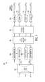
- FIG. 1is a block diagram of a system according to an embodiment of the present invention.
- the system 100is comprised of a DS3 Line Interface Unit (LIU) 102 , an inverse multiplexer 104 to split the DS3 signal into four streams with overhead to permit proper reassembly, and four modulators 106 a - 106 d to drive the data onto the twisted pair.
- the twisted pairsfeed four demodulators 106 a - 106 d which provide the output to the multiplexer 104 to reassemble the data in the proper order.
- LIULine Interface Unit
- FIG. 1is shown with various functions, such as multiplexing and inverse multiplexing, combined in one component block. However, separate components could easily be used to perform corresponding functions, such as modulating and demodulating, and so on, without departing from the spirit of the invention.
- An identifieris preferably encoded into the streams to allow the system 100 to correct a common wiring error where pairs are swapped.
- the data on the streamspreferably employs Reed Solomon error correction coding and interleaving. Thus, short bursts of errors are spread over many Reed Solomon blocks to improve error correction performance.
- two types of systems 100are used at either end of the four twisted pair. These are referred to as the Line Unit and the Remote Unit, corresponding generally to the end of the line closer to the central office (CO), and the end closer to the customer equipment, respectively.
- the Line Unit and Remote Unitdiffer in the frequency plan of the modulators.
- the Line Unitwill preferably transmit on a low frequency band and receive on the high frequency band, while the Remote Unit will preferably transmit on the high frequency band and receive on the low frequency band.
- a Line Unitwill communicate with a Remote Unit at the modem interfaces.
- FIG. 1shows the basic signal flow within embodiments of the present invention.
- One modemis dedicated to each twisted pair.
- the DS3 LIU 102provides the standard interface for the DS3 signal. It is capable of executing a loopback in either direction as indicated by the dashed lines.
- the received part of the DS3 inputis examined for proper framing and any embedded alarm signals. If a problem is detected, the unit may replace the received DS3 with either an IDLE code, an Alarm Indication Signal (AIS), or the unit may not respond depending on switch settings provisioned by the user. The same operation is performed in the transmitted DS3 direction.
- AISAlarm Indication Signal
- the DS3 signalmay include a Far End Alarm and Control (FEAC) channel embedded in the overhead. If so, embodiments of the invention can be provisioned to respond to the DS3 loopback and DS3 loop down or Network Interface Unit (NIU) loopback and NIU loop down codes. While this is a normal part of most systems employing DS3 interfaces, embodiments of the present invention advantageously have the ability to handle loopbacks in tandem arrangements which would be typical in redundant installations.
- FEACFar End Alarm and Control
- FIG. 2shows an exemplary application for embodiments of the present invention during a routine test of the system in a representative telephone company application.
- the equipment at the central officeis replaced by a DS 3 Test Set 108 capable of issuing the loopback code.
- the DS3 Network Interface Unit (NIU) 110would respond to the NIU loopback code and the remote terminal equipment 112 would respond to the DS3 FEAC loopback. If the end unit 100 simply responded to either of the loopback codes, the NIU 110 and/or remote terminal equipment 112 would not be able to respond to that loopback.
- NIUNetwork Interface Unit
- embodiments of the present inventionpreferably respond to either loopback code as provisioned by the user, but the user must configure the number of times that the loopback code must appear in order for the loopback to be executed by the system 100 .
- the Remote Unit 100 a farthest from the test setwill be provisioned to respond to the second loopback command.
- the first loopback commandwill normally be reserved for the NIU 110 or terminating equipment 112 .
- the two loopback commandsare preferably sent without an intervening loop down command.
- the Line Unit 100 bclosest to the test equipment 108 , preferably responds to a third consecutive loopback command without an intervening loop down command.
- Embodiments of the present inventionadvantageously have the ability to support a redundant implementation.
- the number of twisted pair requiredis increased to eight pairs.
- the DS3 at each endis a shared interface. Because DS3 signals will not tolerate a double termination or bridging, the DS3 signal must be routed to only one of the end units at a time, as illustrated in FIG. 3 . Thus, relays 154 or other switching mechanisms in the chassis will route the DS3 signals to the appropriate end unit 100 . Thus, if one set of twisted pair 156 becomes damaged or broken, the switches at either end route the DS3 signal to the backup set of twisted pair 158 through the corresponding end units 100 .
- the chassispreferably includes communication links between the units to permit the switch to protect operation.
- FIG. 4One embodiment exemplified in FIG. 4 has DS3 interface 116 and DS3 interface 118 on front of the unit for use in applications such as remote telephone company enclosures. These connections automatically switch to the chassis to be controlled by relays 154 or other switching mechanisms for redundant implementations and communication with a neighboring unit.
- One embodimentutilizes 1:1 protection switching so that identical end units 100 may be utilized as standby units as contrasted with other methods whereby more than one unit 100 and separate control circuitry are used to provide protection switching.
- the preferred embodimentthereby offers smaller size, less complexity and requires fewer units to provide protection switching.
- This embodiment of the present inventionis a module, approximately 5.75′′ ⁇ 5.25′′ ⁇ 1.5′′. It is comprised of three circuit boards. Two of the circuit boards contain the modems. The remaining board, with an edge finger connector, contains the power supply, microprocessor, DS3 interface 102 , DS3 framers 114 a , 114 b , multiplexer 104 , and inverse multiplexer 104 .
- the DS3 framers 114 a , 114 b , the multiplexer 104 , and the inverse multiplexer 104are preferably implemented within a single field programmable gate array (FPGA).
- FPGAfield programmable gate array
- FIG. 4illustrates a front panel 160 of an end unit 100 according to an embodiment of the invention.
- Two BNC connectors 116 , 118provide the interface for the DS3 port.
- a switch 120 below the BNC connectorsallows the user to select the line build out for the DS3 as either long or short.
- a short build outis preferably used for lines less than 225 feet and the long build out is intended to be used with cable 255-450 feet.
- a pushbutton 122 below the build out switchpreferably allows the user to place the unit in loopback manually.
- the 9 pin D connector 124carries a serial port which can be accessed from a computer.
- the usercan view the status of the unit and past history of performance in 15 minute blocks up to one day. There is also preferably a seven day history in one day blocks.
- the usercan view Errored Seconds, Severely Errored Seconds, Loss of Signal Seconds, and Line Code Violations for the DS3 interface. Data is collected for each OSP interface: Failure Counter, Reed-Solomon Error counter, Errored Seconds, Severely Errored Seconds, and Loss of Signal Seconds.
- the two square connectors 126 , 128 on the front panelare preferably type RJ45. Each RJ45 will interface to 2 twisted pairs.
- This embodimentalso includes six LED's 130 a - 130 f on the front panel 160 .
- the front panel LED'sprovide the user with basic status information which can be used to troubleshoot most problems encountered without additional equipment.
- One LEDis a unit LED 130 a , which provides status information on the unit 100 .
- the unit LED 130 aWhen power is applied to the unit 100 , but there is a failure, the unit LED 130 a turns red. Green indicates that power is applied and the unit 100 is functioning properly. In a redundant application as described above, green indicates that the unit 100 is in active mode. If the unit 100 is in a redundant application, but is in standby mode, the unit LED 130 a turns yellow.
- Another LED in this embodimentis the DS3 LED 130 b .
- the DS3 LEDturns red to indicate a failure at the DS3 interface. Yellow indicates that a remote alarm has been received. Flashing green indicates that the unit is in DS3 loopback mode, and solid green indicates normal operation.
- a DS3 remote alarmcan be either an AIS, IDLE, or RDI receives at the DS3 port.
- a DS3 failureincludes loss of signal (LOS) or loss of DS3 framing.
- This embodimentalso includes four OSP LED's 130 c - 130 f . For each of these LED's, red indicates no signal, and green indicates that a signal is present and that the link is synchronized.
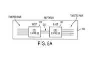
- FIGS. 5 a and 5 billustrate embodiments of the present invention used in repeater configurations representative of typical telephone company applications.
- FIG. 5 aillustrates a basic repeater 166 arrangement. Two end units 100 are connected to each other through the DS3 interface.
- “West”refers to the end of the communication line closest to a Central Office (CO) 162 .
- “East”refers to the end of the communication line closest to the customer premises equipment (CPE) 164 .
- COCentral Office
- CPEcustomer premises equipment
- FIG. 5 billustrates several end units arranged in a double repeater 166 arrangement.
- Each repeater 166is comprised of a West end unit 100 and an East end unit 100 , with the end units 100 connected together through their respective DS3 interfaces.
- Repeater # 1 166is closest to the customer premises equipment, and repeater # 2 166 is closest to the CO.
- the end units 100In order to function optimally, the end units 100 must be configured such that they function as part of a repeater or not. Referring to FIG. 5 b , the end units 100 at the CO 162 and at the CPE 164 are not configured as repeaters. End units that are configured as repeaters are further configured as West end units or East end units, as appropriate.
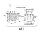
- Provisioning of the unitis preferably accomplished through a set of switches 132 on the main board.
- An exemplary switch arrangement 132is illustrated in FIG. 6 .
- the four switches at the leftare used to indicate the exact position of the end unit 100 in the network.
- switches 134 , 136 labeled “NO REPEATER”should be in the up position.
- the NET (CO) end unit 100should have the “Line Unit” (LU) switch 138 in the up position and the “Remote Unit” (RU) switch 140 in the down position.
- the EQUIP (CPE) end unit 100should have the LU switch 138 in the down position and the RU switch 140 in the up position.
- the repeaters 166must have either switch 134 or switch 136 in the up position to indicate which repeater the end unit 100 is a member of.
- the LU switch 138also acts as a “West” switch in the case of a repeater, and is in the up position to indicate that the end unit 100 is the West end unit of the particular repeater.
- the RU switch 140acts as an “East” switch in the case of an end unit 100 that is a member of a repeater, and is in the up position to indicate that the particular end unit 100 is the East end unit.
- each end unit 100 in the chainis configured according to its position in the network. Therefore, end units 100 according to an embodiment of the present invention are capable of responding to the loopback code in the appropriate way. It is assumed that equipment at the customer premise other than the end unit 100 will respond to a loopback code when the loopback code is first issued. All end units 100 in the chain will preferably ignore the first loopback code for that reason. The end unit 100 at the customer premise will respond to the 2 nd consecutive loopback code without an intervening loop down code. Repeater # 1 east will respond to the 3 rd loopback code. Repeater 1 west will respond to the 4 th loopback code. Repeater 2 east will respond to the 5 th loopback code.
- Repeater 2 westwill respond to the 6 th loopback code.
- the NET (CO) end unit 100will respond to the 7 th consecutive loopback code without an intervening loop down code. In this manner, each link in the repeater chain can advantageously be tested in turn.
- the setting of the first four switchesis not important.
- the end unit 100will respond to two different loopback codes, the DS3 LINE loopback and the NIU loopback.
- One switch 142selects which code will cause the end unit 100 to enter loopback.
- Switch 144selects whether the 20 minute timer release function is enabled or not.
- Selection switch 146configures the end unit 100 for either M13 or C-BIT framing pattern in the DS3 signal.
- the end unit 100supports both the older M13 framing pattern or the C-Bit-Parity framing pattern which permits loopback commands to be embedded in the signal overhead.
- Two switches 148 , 150allow the user to program the response of the end unit to a loss of signal.
- the end unitwill preferably respond in one of three ways. First, an AIS signal will be transmitted if AIS switch 148 is in the up position. An IDLE signal will be transmitted if IDLE switch 150 is in the up position. Finally, the end unit 100 preferably enters loopback mode if the AIS switch 148 and IDLE switch 150 are both in the down position until the input signal is regained. Finally, in this example, a spare switch 152 is provided to allow for expanded capabilities.
- a DS3 input signalis demultiplexed into four modulated signals at 12.96 Mbps each. Conversely, there are four modulated inputs at 12.96 Mbps each that are remultiplexed into a single DS3 for transmission.
- the end unit 100transmits and receives simultaneously on all twisted pairs.
- the upstream and downstream datais divided into separate frequency bands. This requires two different sets of filters to be implemented.
- a Network Unit device(farthest “west” or towards the CO) will use the low frequency band for transmit and the high frequency band for receive.
- the Remote Unit devicewill use the high band for transmit and the low band for receive.
- the transmit high band filterhas a different characteristic than the receive high band filter.
- the transmit low band filterhas a different characteristic than the receive low band filter. Therefore, in one embodiment, only the required filters are included in a particular end unit 100 , depending on whether it is a Network Unit (towards the CO) or a Remote Unit (towards the CPE). As a result, end units according to one embodiment of the invention can be kept smaller because they do not include unnecessary extra filters as would be needed in a device capable of functioning either as a Network Unit or as a Remote Unit. Alternately, the end unit 100 can be populated with all filters, and configured to select the ones needed for the application using switches.
- the processoris programmed to function as either a Network Unit or a Remote Unit, but only the appropriate filters are included. A zero ohm jumper is used to indicate to the processor whether the device is a Network Unit or a Remote Unit.
- the DS3 signal received from the DS3 interface at the left of the block diagramis framed. If a loss of frame or a loss of signal is detected for 2.5 seconds, the alarm insertion logic will inject the AIS toward the modem interface 106 through Alarm Insertion Unit 115 a .
- the DS3 framer 114 bwhich receives data from the modem side, can also cause the AIS to be sent to the DS3 side after a 2.5 second soaking period. If any of the four modem links 106 a - 106 d experiences a receive problem such as loss of signal or loss of synchronization, the DS3 Alarm Insertion Device 115 b will inject an AIS toward the DS3 port after a 2.5 second soaking period.
- the modem interfacespreferably have a remote defect indication mechanism. If a modem input is lost, the remote defect indication is sent to the far end.
- the alarm contactsare divided as either remote or local alarm.
- a local alarmis a loss of received signal from either the DS3 or any of the modem ports.
- the second contact closureindicates remote alarms. If the AIS, IDLE, or RDI is detected on either incoming directions, the remote alarm contact is closed. The modem remote defect indication that will close the remote alarm contact.
- the multiplexing operationwill divide the DS3 into four streams. Each modem stream will accept every fourth bit from the DS3. This results in four parallel data streams at 11.184 Mbps. With added overhead, the modem streams carry 12.96 Mbps. In this embodiment, a 260 byte packet is generated. Two bytes are used for synchronization, three are control bytes, and 16 bytes are used for Reed Solomon error correction. 236 bytes carry information, resulting in a 90.77% efficiency and 11.76 Mbps of capacity. In order to be able to reconstruct the DS3 stream at the far end, additional structure and overhead is included in each stream. Each 1 ⁇ 4 DS3 stream is placed into 64 byte (512 bit) packets by the framer 105 .
- the first byteis a fixed framing pattern allowing the receiver to find the start of the packet.
- the second bytehas a four bit packet number and two bit stream number which is used at the receiver to join four packets from the four corresponding modem streams together to form a DS3 stream.
- the packet numberis incremented as each packet is sent.
- the packetsenter the four transmitters simultaneously. Variable delays in the transmitters and receivers will cause some skew in the data as it passes through the modems and twisted pair portion of the system.
- the inverse multiplexerat the receiver, buffers the packets, and aligns the data by matching the four bit packet numbers and arranging data according to the two bit stream number. The remaining two bits of the 2 nd byte are used in the packet control stuffing.
- 62 bytes of the 64 byte packetare the actual data.
- the systemhas 11.39 Mbps of data capacity compared to the 11.184 Mbps of capacity which is required. If 61 of the 62 information bytes are used, the resulting data rate is 11.21 Mbps which is very close to the nominal rate. Using 60 of the 62 data bytes, the data rate is only 11.03 Mbps.
- the inverse multiplexer functionwill vary the number of used data bytes in the 64 byte packet.
- 61 bytes per packetwould have valid data with an occasional packet that contained only 60 valid data bytes.
- the DS3is running faster than nominal, and the modem link is running slower than nominal, resulting in the need for an occasional 62 byte information packet.
- the remaining two bits in the 2 nd packet bytecontrol this stuffing.
- Table 1contains exemplary stuffing codes, and the corresponding number of valid information bytes carried in a packet.
- Table 2illustrates the structure of the 64 byte packet generated for each modem data stream according to an embodiment of the invention.
- a rotating packet index numbercan be generated at the transmit end and included packet header to assist in reassembling the data streams into a DS3 signal at the receive end.
- the packet index numberis a four bit field that rotates through values 0000 through 1111. Each sequential packet at the receive end is transmitted on the next available twisted pair port. At the receive end, groups of sixteen packets are reassembled in order, according to the packet index numbers.
Landscapes
- Engineering & Computer Science (AREA)
- Power Engineering (AREA)
- Computer Networks & Wireless Communication (AREA)
- Signal Processing (AREA)
- Maintenance And Management Of Digital Transmission (AREA)
- Data Exchanges In Wide-Area Networks (AREA)
Abstract
Description
| TABLE 1 | |||
| Valid information | |||
| Stuffing code | bytes | ||
| 00 | 59 | ||
| 01 | 60 | ||
| 10 | 61 | ||
| 11 | 62 | ||
| TABLE 2 |
| 64 byte packet |
| Sync Code | 11010100 | |||
| 4 bits (counter 0-15) | Single | |||
| byte | ||||
| Stream | ||||
| 2 bits (1 of 4 streams) | ||||
| Stuffing | ||||
| 2 bits (59-62 valid | ||||
| code | data bytes) | |||
| Information | 59 data bytes always | |||
| valid | ||||
| Stuff byte | Valid if stuff code ≧ 01 | |||
| Stuff byte | Valid if stuff code ≧ 10 | |||
| Stuff byte | Valid if stuff code = 11 | |||
Claims (33)
Priority Applications (1)
| Application Number | Priority Date | Filing Date | Title |
|---|---|---|---|
| US10/617,363US7738511B2 (en) | 2003-07-11 | 2003-07-11 | Apparatus and method for transmitting a DS3 signal over multiple twisted pair conductors |
Applications Claiming Priority (1)
| Application Number | Priority Date | Filing Date | Title |
|---|---|---|---|
| US10/617,363US7738511B2 (en) | 2003-07-11 | 2003-07-11 | Apparatus and method for transmitting a DS3 signal over multiple twisted pair conductors |
Publications (2)
| Publication Number | Publication Date |
|---|---|
| US20050008041A1 US20050008041A1 (en) | 2005-01-13 |
| US7738511B2true US7738511B2 (en) | 2010-06-15 |
Family
ID=33564947
Family Applications (1)
| Application Number | Title | Priority Date | Filing Date |
|---|---|---|---|
| US10/617,363Expired - Fee RelatedUS7738511B2 (en) | 2003-07-11 | 2003-07-11 | Apparatus and method for transmitting a DS3 signal over multiple twisted pair conductors |
Country Status (1)
| Country | Link |
|---|---|
| US (1) | US7738511B2 (en) |
Families Citing this family (6)
| Publication number | Priority date | Publication date | Assignee | Title |
|---|---|---|---|---|
| US8571070B2 (en)* | 2005-12-02 | 2013-10-29 | Broadcom Corporation | Method and system for speed negotiation for twisted pair links in fibre channel sytems |
| US7613125B2 (en)* | 2005-12-28 | 2009-11-03 | Alcatel-Lucent Usa Inc. | Method and apparatus for temporal alignment of multiple parallel data streams |
| WO2008095249A1 (en)* | 2007-02-09 | 2008-08-14 | Clipsal Australia Pty Ltd | Selective communications network functionality |
| DE102010017528A1 (en) | 2010-06-23 | 2011-12-29 | Adva Ag Optical Networking | Method and receiving device for determining the assignment of sub-signals transmitted in inverse multiplex, in particular via an optical transport network (OTN), to the transmission links carrying them |
| US9590820B1 (en) | 2011-09-02 | 2017-03-07 | Juniper Networks, Inc. | Methods and apparatus for improving load balancing in overlay networks |
| US10103850B2 (en)* | 2014-12-22 | 2018-10-16 | Arista Networks, Inc. | System and method of using undirectional links for tap aggregation |
Citations (35)
| Publication number | Priority date | Publication date | Assignee | Title |
|---|---|---|---|---|
| US3692964A (en)* | 1969-12-24 | 1972-09-19 | Sits Soc It Telecom Siemens | Remote-testing arrangement for two-way transmission channel of pcm telecommunication system |
| US5060226A (en)* | 1990-07-05 | 1991-10-22 | Phoenix Microsystems, Inc. | Telecommunications network test system |
| US5437023A (en)* | 1994-02-09 | 1995-07-25 | Teltrend, Inc. | Noise-tolerant address transmission system for digital telecommunication network |
| US5608733A (en)* | 1994-11-29 | 1997-03-04 | Valle; Richard | ATM inverse multiplexing |
| US20010008534A1 (en) | 1995-11-22 | 2001-07-19 | Depue Clayton S. | Digital subscriber line multiplexer |
| US6275510B1 (en)* | 1997-11-03 | 2001-08-14 | Carrier Access Corporation | Telecommunications multiplexer |
| US20010028644A1 (en) | 1997-12-31 | 2001-10-11 | Farhad Barzegar | Multifunction interface facility connecting wideband multiple access subscriber loops with various networks |
| US20010040042A1 (en) | 1999-08-31 | 2001-11-15 | Stipes Jason A. | High speed data cable having individually shielded twisted pairs |
| US20020007490A1 (en) | 1998-08-03 | 2002-01-17 | Jeffery Ross A. | Audio/video and data signal redistribution system |
| US20020018491A1 (en) | 1995-03-20 | 2002-02-14 | Nicholas A. Balatoni | Plug-in multiplexer |
| US20020027927A1 (en) | 1997-12-31 | 2002-03-07 | Farhad Barzegar | Circuit to provide backup telephone service for a multiple service access system using a twisted pair |
| US20020039359A1 (en) | 1997-12-31 | 2002-04-04 | At&T Corporation | Hybrid fiber twisted pair local loop network service architecture |
| US20020044597A1 (en) | 1997-12-31 | 2002-04-18 | Shively Richard Robert | Spread spectrum bit allocation algorithm |
| US20020056137A1 (en) | 1994-01-05 | 2002-05-09 | Cybex Computer Products Corporation | Twisted pair communications line system |
| US20020080825A1 (en)* | 2000-12-23 | 2002-06-27 | Alcatel | Method and compensation module for the phase compensation of clock signals |
| US20020080933A1 (en) | 2000-12-21 | 2002-06-27 | Hansen Carl Christian | Power cutback configuration of digital subscriber line transceivers using public switched telephone network signaling |
| US20020097105A1 (en) | 2001-01-23 | 2002-07-25 | Adc Telecommunications, Inc. | Multi-circuit signal transformer |
| US20020167970A1 (en) | 1999-02-23 | 2002-11-14 | Ameritech Corporation | Method and system for conveying multiple calls on a single telephone line |
| US20020176139A1 (en)* | 2001-05-02 | 2002-11-28 | Louis Slaughter | SONET capable millimeter wave communication system |
| US20030097624A1 (en)* | 2001-08-15 | 2003-05-22 | Barton Bruce R. | Remote module for a communications network |
| US20030107999A1 (en)* | 2000-05-22 | 2003-06-12 | Shimon Peleg | Inverse multiplexer device |
| US20030142759A1 (en) | 1998-06-19 | 2003-07-31 | Anderson Carl William | Transmission system for reduction of amateur radio interference |
| US20030169780A1 (en)* | 2000-12-29 | 2003-09-11 | Brana Kukic | Method and system for establishing link bit rate for inverse multiplexed data streams |
| US6657953B1 (en)* | 1997-06-27 | 2003-12-02 | Fujitsu Limited | Signal loopback device |
| US6775305B1 (en)* | 1999-10-21 | 2004-08-10 | Globespanvirata, Inc. | System and method for combining multiple physical layer transport links |
| US20040179486A1 (en)* | 1997-07-15 | 2004-09-16 | Viasat, Inc. | Method and apparatus for segmentation, reassembly and inverse multiplexing of packets and ATM cells over satellite/wireless networks |
| US6928056B2 (en)* | 2000-12-29 | 2005-08-09 | Nokia Networks Oy | System and method for distribution of a data stream from high-to-low-to-high bandwidth links |
| US20050220180A1 (en)* | 1999-02-23 | 2005-10-06 | Tuvia Barlev | High speed access system over copper cable plant |
| US6967589B1 (en)* | 2000-08-11 | 2005-11-22 | Oleumtech Corporation | Gas/oil well monitoring system |
| US7006500B1 (en)* | 2002-04-26 | 2006-02-28 | Valo, Inc. | Methods, apparatuses and systems facilitating data transmission across bonded communications paths |
| US7054376B1 (en)* | 1999-05-27 | 2006-05-30 | Infineon Technologies Ag | High data rate ethernet transport facility over digital subscriber lines |
| US7058011B1 (en)* | 2001-02-26 | 2006-06-06 | Calix Networks, Inc. | N to one and one to one equipment protection switching |
| US7065104B1 (en)* | 2000-12-28 | 2006-06-20 | Cisco Technology, Inc. | Method and system for managing inverse multiplexing over ATM |
| US7230977B1 (en)* | 2000-05-21 | 2007-06-12 | Surf Communication Solutions Ltd. | Back-to-back modem repeater |
| US20080095191A1 (en)* | 2002-06-26 | 2008-04-24 | Standard Microsystems Corp. | Communication System and Method for Sending Isochronous Streaming Data Within a Frame Segment Using a Signaling Byte |
- 2003
- 2003-07-11USUS10/617,363patent/US7738511B2/ennot_activeExpired - Fee Related
Patent Citations (37)
| Publication number | Priority date | Publication date | Assignee | Title |
|---|---|---|---|---|
| US3692964A (en)* | 1969-12-24 | 1972-09-19 | Sits Soc It Telecom Siemens | Remote-testing arrangement for two-way transmission channel of pcm telecommunication system |
| US5060226A (en)* | 1990-07-05 | 1991-10-22 | Phoenix Microsystems, Inc. | Telecommunications network test system |
| US20020056137A1 (en) | 1994-01-05 | 2002-05-09 | Cybex Computer Products Corporation | Twisted pair communications line system |
| US5437023A (en)* | 1994-02-09 | 1995-07-25 | Teltrend, Inc. | Noise-tolerant address transmission system for digital telecommunication network |
| US5608733A (en)* | 1994-11-29 | 1997-03-04 | Valle; Richard | ATM inverse multiplexing |
| US20020018491A1 (en) | 1995-03-20 | 2002-02-14 | Nicholas A. Balatoni | Plug-in multiplexer |
| US20010008534A1 (en) | 1995-11-22 | 2001-07-19 | Depue Clayton S. | Digital subscriber line multiplexer |
| US6657953B1 (en)* | 1997-06-27 | 2003-12-02 | Fujitsu Limited | Signal loopback device |
| US20040179486A1 (en)* | 1997-07-15 | 2004-09-16 | Viasat, Inc. | Method and apparatus for segmentation, reassembly and inverse multiplexing of packets and ATM cells over satellite/wireless networks |
| US6275510B1 (en)* | 1997-11-03 | 2001-08-14 | Carrier Access Corporation | Telecommunications multiplexer |
| US20020027927A1 (en) | 1997-12-31 | 2002-03-07 | Farhad Barzegar | Circuit to provide backup telephone service for a multiple service access system using a twisted pair |
| US20020027876A1 (en) | 1997-12-31 | 2002-03-07 | Farhad Barzegar | Circuit to provide backup telephone service for a multiple service access system using a twisted pair |
| US20020039359A1 (en) | 1997-12-31 | 2002-04-04 | At&T Corporation | Hybrid fiber twisted pair local loop network service architecture |
| US20020044597A1 (en) | 1997-12-31 | 2002-04-18 | Shively Richard Robert | Spread spectrum bit allocation algorithm |
| US20010028644A1 (en) | 1997-12-31 | 2001-10-11 | Farhad Barzegar | Multifunction interface facility connecting wideband multiple access subscriber loops with various networks |
| US20030142759A1 (en) | 1998-06-19 | 2003-07-31 | Anderson Carl William | Transmission system for reduction of amateur radio interference |
| US20020007490A1 (en) | 1998-08-03 | 2002-01-17 | Jeffery Ross A. | Audio/video and data signal redistribution system |
| US20020167970A1 (en) | 1999-02-23 | 2002-11-14 | Ameritech Corporation | Method and system for conveying multiple calls on a single telephone line |
| US20050220180A1 (en)* | 1999-02-23 | 2005-10-06 | Tuvia Barlev | High speed access system over copper cable plant |
| US7054376B1 (en)* | 1999-05-27 | 2006-05-30 | Infineon Technologies Ag | High data rate ethernet transport facility over digital subscriber lines |
| US20010040042A1 (en) | 1999-08-31 | 2001-11-15 | Stipes Jason A. | High speed data cable having individually shielded twisted pairs |
| US6775305B1 (en)* | 1999-10-21 | 2004-08-10 | Globespanvirata, Inc. | System and method for combining multiple physical layer transport links |
| US7230977B1 (en)* | 2000-05-21 | 2007-06-12 | Surf Communication Solutions Ltd. | Back-to-back modem repeater |
| US20030107999A1 (en)* | 2000-05-22 | 2003-06-12 | Shimon Peleg | Inverse multiplexer device |
| US6967589B1 (en)* | 2000-08-11 | 2005-11-22 | Oleumtech Corporation | Gas/oil well monitoring system |
| US20020080933A1 (en) | 2000-12-21 | 2002-06-27 | Hansen Carl Christian | Power cutback configuration of digital subscriber line transceivers using public switched telephone network signaling |
| US20020080825A1 (en)* | 2000-12-23 | 2002-06-27 | Alcatel | Method and compensation module for the phase compensation of clock signals |
| US7065104B1 (en)* | 2000-12-28 | 2006-06-20 | Cisco Technology, Inc. | Method and system for managing inverse multiplexing over ATM |
| US20030169780A1 (en)* | 2000-12-29 | 2003-09-11 | Brana Kukic | Method and system for establishing link bit rate for inverse multiplexed data streams |
| US6928056B2 (en)* | 2000-12-29 | 2005-08-09 | Nokia Networks Oy | System and method for distribution of a data stream from high-to-low-to-high bandwidth links |
| US20030012362A1 (en) | 2001-01-23 | 2003-01-16 | Adc Telecommunications, Inc. | Multi-circuit signal transformer |
| US20020097105A1 (en) | 2001-01-23 | 2002-07-25 | Adc Telecommunications, Inc. | Multi-circuit signal transformer |
| US7058011B1 (en)* | 2001-02-26 | 2006-06-06 | Calix Networks, Inc. | N to one and one to one equipment protection switching |
| US20020176139A1 (en)* | 2001-05-02 | 2002-11-28 | Louis Slaughter | SONET capable millimeter wave communication system |
| US20030097624A1 (en)* | 2001-08-15 | 2003-05-22 | Barton Bruce R. | Remote module for a communications network |
| US7006500B1 (en)* | 2002-04-26 | 2006-02-28 | Valo, Inc. | Methods, apparatuses and systems facilitating data transmission across bonded communications paths |
| US20080095191A1 (en)* | 2002-06-26 | 2008-04-24 | Standard Microsystems Corp. | Communication System and Method for Sending Isochronous Streaming Data Within a Frame Segment Using a Signaling Byte |
Non-Patent Citations (4)
| Title |
|---|
| ADC Telecommunications "A":ADC Telecommunications, DS3/STS1 PBOR Installation Dwg, Rev B, Jul. 23, 1998.* |
| ADC Telecommunications "B": ADC Telecommunications, DS3/STS-1 Repeater Products, Sep. 2000.* |
| ADC Telecommunications "C": ADC Telecommunications, Installation Dwg 16 PosChassis, RevC, Jan. 4, 2002.* |
| Sklower et al., The PPP Multilink Protocol, Aug. 1996, Network Working Group, Request for Comments: 1990.* |
Also Published As
| Publication number | Publication date |
|---|---|
| US20050008041A1 (en) | 2005-01-13 |
Similar Documents
| Publication | Publication Date | Title |
|---|---|---|
| CA2206677C (en) | Burst-error resistant atm microwave link and network | |
| US7133441B1 (en) | High speed access system over copper cable plant | |
| US5422876A (en) | Out-of-band loopback control scheme | |
| US6853680B1 (en) | System and process for embedded cable modem in a cable modem termination system to enable diagnostics and monitoring | |
| US4633246A (en) | Time divison multiplex ring | |
| CA2164867C (en) | Added bit signalling in a telecommunications system | |
| US6611526B1 (en) | System having a meshed backplane and process for transferring data therethrough | |
| US7606886B1 (en) | Method and system for providing operations, administration, and maintenance capabilities in packet over optics networks | |
| FI107204B (en) | Optical data network | |
| US6160806A (en) | High density unit shelf with network interface cards and method | |
| JPH07212382A (en) | Communication system | |
| JPH07202924A (en) | Communication system | |
| JPH10505974A (en) | Integrated multi-structure digital cross-connect integrated office link | |
| US7738511B2 (en) | Apparatus and method for transmitting a DS3 signal over multiple twisted pair conductors | |
| US7774493B1 (en) | Frame structure and method for wavelength concatenated channel framing | |
| CN100555917C (en) | Optical transferred synthetized accessing PDH device in multiple services | |
| JP5357436B2 (en) | Transmission equipment | |
| Cisco | Service Interface (Line) Cards | |
| Cisco | Service Interface (Line) Cards | |
| Cisco | Service Interface (Line) Cards | |
| Cisco | Service Interface (Line) Cards | |
| Cisco | Service Interface (Line) Cards | |
| Cisco | Service Interface (Line) Cards | |
| JP3466927B2 (en) | Transmission management device and transmission management method | |
| US7106789B1 (en) | Method and apparatus for provisioning TDM and packet based communications on a VDSL communication medium |
Legal Events
| Date | Code | Title | Description |
|---|---|---|---|
| AS | Assignment | Owner name:HUBBELL INCORPORATED, CONNECTICUT Free format text:ASSIGNMENT OF ASSIGNORS INTEREST;ASSIGNORS:WU, ZHANGYI;MILLER, GARY MICHAEL;SCLATER, JAMES EDWARD;AND OTHERS;REEL/FRAME:014806/0799;SIGNING DATES FROM 20031208 TO 20031210 Owner name:HUBBELL INCORPORATED,CONNECTICUT Free format text:ASSIGNMENT OF ASSIGNORS INTEREST;ASSIGNORS:WU, ZHANGYI;MILLER, GARY MICHAEL;SCLATER, JAMES EDWARD;AND OTHERS;SIGNING DATES FROM 20031208 TO 20031210;REEL/FRAME:014806/0799 | |
| AS | Assignment | Owner name:PULSE COMMUNICATIONS, INC., VIRGINIA Free format text:ASSIGNMENT OF ASSIGNORS INTEREST;ASSIGNOR:HUBBELL INCORPORATED;REEL/FRAME:014901/0546 Effective date:20040113 Owner name:PULSE COMMUNICATIONS, INC.,VIRGINIA Free format text:ASSIGNMENT OF ASSIGNORS INTEREST;ASSIGNOR:HUBBELL INCORPORATED;REEL/FRAME:014901/0546 Effective date:20040113 | |
| FEPP | Fee payment procedure | Free format text:PAYOR NUMBER ASSIGNED (ORIGINAL EVENT CODE: ASPN); ENTITY STATUS OF PATENT OWNER: LARGE ENTITY | |
| REMI | Maintenance fee reminder mailed | ||
| FPAY | Fee payment | Year of fee payment:4 | |
| SULP | Surcharge for late payment | ||
| AS | Assignment | Owner name:ENGINUITY COMMUNICATIONS CORPORATION, ILLINOIS Free format text:ASSIGNMENT OF ASSIGNORS INTEREST;ASSIGNOR:PULSE COMMUNICATIONS, INC.;REEL/FRAME:039519/0030 Effective date:20160713 | |
| FEPP | Fee payment procedure | Free format text:MAINTENANCE FEE REMINDER MAILED (ORIGINAL EVENT CODE: REM.) | |
| LAPS | Lapse for failure to pay maintenance fees | Free format text:PATENT EXPIRED FOR FAILURE TO PAY MAINTENANCE FEES (ORIGINAL EVENT CODE: EXP.) | |
| STCH | Information on status: patent discontinuation | Free format text:PATENT EXPIRED DUE TO NONPAYMENT OF MAINTENANCE FEES UNDER 37 CFR 1.362 | |
| FP | Lapsed due to failure to pay maintenance fee | Effective date:20180615 | |
| FP | Lapsed due to failure to pay maintenance fee | Effective date:20180615 |