US7738230B2 - Nonvolatile status indicator switch - Google Patents
Nonvolatile status indicator switchDownload PDFInfo
- Publication number
- US7738230B2 US7738230B2US11/969,861US96986108AUS7738230B2US 7738230 B2US7738230 B2US 7738230B2US 96986108 AUS96986108 AUS 96986108AUS 7738230 B2US7738230 B2US 7738230B2
- Authority
- US
- United States
- Prior art keywords
- fault
- circuit
- signal
- relay
- indicator circuit
- Prior art date
- Legal status (The legal status is an assumption and is not a legal conclusion. Google has not performed a legal analysis and makes no representation as to the accuracy of the status listed.)
- Expired - Fee Related, expires
Links
Images


Classifications
- G—PHYSICS
- G08—SIGNALLING
- G08B—SIGNALLING OR CALLING SYSTEMS; ORDER TELEGRAPHS; ALARM SYSTEMS
- G08B3/00—Audible signalling systems; Audible personal calling systems
- G08B3/10—Audible signalling systems; Audible personal calling systems using electric transmission; using electromagnetic transmission
- H—ELECTRICITY
- H01—ELECTRIC ELEMENTS
- H01H—ELECTRIC SWITCHES; RELAYS; SELECTORS; EMERGENCY PROTECTIVE DEVICES
- H01H47/00—Circuit arrangements not adapted to a particular application of the relay and designed to obtain desired operating characteristics or to provide energising current
- H01H47/002—Monitoring or fail-safe circuits
- H—ELECTRICITY
- H01—ELECTRIC ELEMENTS
- H01H—ELECTRIC SWITCHES; RELAYS; SELECTORS; EMERGENCY PROTECTIVE DEVICES
- H01H50/00—Details of electromagnetic relays
- H01H50/08—Indicators; Distinguishing marks
Definitions
- the present inventionrelates generally to the use of relays in aircraft electrical systems and more particularly to systems and methods for saving and indicating the status of a detected fault in the relays.
- the primary functions of an aircraft electrical systemare to generate, regulate and distribute electrical power throughout the aircraft.
- power sourcescan include engine driven AC generators, auxiliary power units, external power and ram air turbines.
- Aircraft electrical componentsoperate on many different voltages levels using both AC and DC. However, most of the aircraft systems use 115V AC at 400 Hz or 28V DC. Further, 26V AC is also used in some aircraft for lighting purposes.
- DC poweris generally provided by “self-exciting” generators containing electromagnets, where the power is generated by a commutator which regulates the output voltage of 28V DC.
- AC powernormally at a phase voltage of 115V, is generated by an alternator, generally in a three-phase system and at a frequency of 400 Hz.
- a typical relayincludes contacts that connect to a power supply and contacts that connect to a load. Electromechanical contacts are closed by a magnetic field generated by a coil. The coil is energized by a control current provided to the relay via a control input. Contact closure allows load current to flow.
- Faults in aircraft electrical systemscan be dangerous.
- faults in electrical loadssuch as fuel pumps can result in explosions.
- Examples of faults that can occur in an aircraft electrical systeminclude ground faults (short circuit to ground) and arc faults (shorts between the power lines). Ground faults result in a net current imbalance, while arc faults do not.
- fault interruptersare used for the aircraft electrical systems. These fault interrupters can include a universal fault interrupter (UFI), an arc fault circuit interrupter (AFCI), and thermally tripped circuit breakers (CBs) now commonly installed in cockpits.
- UFIuniversal fault interrupter
- AFCIarc fault circuit interrupter
- CBsthermally tripped circuit breakers
- the inventionrelates to a non-volatile status indicator switch.
- the inventionrelates to an aircraft electrical system including a fault detection circuit coupled to a relay, and a fault indicator circuit coupled to the fault detection circuit and to a control input of the relay, wherein the fault indicator circuit includes a nonvolatile memory element including a potentiometer having a nonvolatile memory, wherein the fault detection circuit is configured to detect a fault and to provide a signal indicative of the fault to the fault indicator circuit, and wherein the fault indicator circuit is configured to respond to the signal indicative of the fault by providing a predetermined control signal to the relay and by storing information indicative of the detection of the fault in the nonvolatile memory.
- the inventionin another embodiment, relates to method for controlling a relay in an airplane electrical system, the method including detecting at least one fault, storing a record of the at least one fault using a potentiometer comprising a solid state nonvolatile memory, maintaining the record of the at least one fault in the absence of power, clearing the record of the at least one fault when a reset signal is received, and opening a relay to stop a flow of current to a load in the airplane electrical system when the at least one fault is stored.
- the inventionin yet another embodiment, relates to a fault indicator circuit including an input logic circuit configured to receive a fault signal indicative of a detection of a fault and a reset signal indicative of a request to reset the fault, and an electromechanical switch coupled to an output of the input logic circuit, where the output of the input logic circuit is derived from the fault signal and the reset signal, wherein the electromechanical switch is configured to control a relay in response to the output of the input logic circuit, and wherein an exterior housing of the electromechanical switch is surrounded by a shielding material that reduces an impact of external magnetic fields on operation of the electromechanical switch.
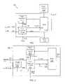
- FIG. 1is a schematic view of an aircraft electrical system in accordance with an embodiment of the present invention.
- FIG. 2is a schematic view of a fault protected relay in accordance with an embodiment of the present invention.
- FIG. 3is a schematic view of a fault indicator circuit in accordance with an embodiment of the present invention.
- FIG. 4is a schematic view of a power supply that can be used to provide power to the fault indicator circuit in accordance with an embodiment of the present invention.
- FIG. 5is a flow chart showing a method of controlling the operation of a relay in response to the detection of a fault in accordance with an embodiment of the present invention.
- FIG. 6is a schematic view of an input logic circuit and a nonvolatile memory that can be used in a fault indicator circuit in accordance with an embodiment of the present invention.
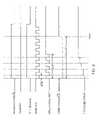
- FIG. 7is a timing diagram illustrating the operation of the input logic circuit and nonvolatile memory element of FIG. 6 to store a fault.
- FIG. 8is a timing diagram illustrating the operation of the input logic circuit and nonvolatile memory element of FIG. 6 to clear a stored fault.
- FIG. 9is a schematic view of a driving circuit for use in a fault indicator circuit in accordance with an embodiment of the present invention.
- FIG. 10is a schematic view of a relay control switch for use in a fault indicator circuit in accordance with an embodiment of the present invention.
- FIG. 11is a schematic view of a visual indicator for use in a fault indicator circuit in accordance with an embodiment of the present invention.
- FIG. 12is a circuit diagram of a fault indicator circuit in accordance with an embodiment of the present invention.
- FIG. 13is a circuit diagram of a power supply assembly for use with a fault indicator circuit in accordance with an embodiment of the present invention.
- FIG. 14is a schematic block diagram of a fault indicator circuit including an electromechanical switch with electromagnetic shielding in accordance with an embodiment of the present invention.
- FIG. 15Ais a schematic block diagram of a fault indicator circuit including a visual indicator indicating a non-fault condition in accordance with an embodiment of the present invention.
- FIG. 15Bis a schematic block diagram of a fault indicator circuit including a visual indicator indicating a fault condition in accordance with an embodiment of the present invention.
- the fault indicator circuitscan be used to interrupt a control signal provided to the relay in the event that a fault condition is detected.
- the interruption of the control signalcan cause the relay to disconnect power from a load.
- the fault indicator circuitincludes a nonvolatile memory for storing information indicative of the existence of a fault. When power is removed from the fault indicator, the nonvolatile memory preserves the fault status information. When power is restored to the relay, the fault indicator circuit can prevent the relay from being activated until the fault is cleared and the monitored device is manually reset.
- the fault indicator circuitis implemented using solid state circuit components.
- solid state nonvolatile memory elementscan be used to store fault status.
- the fault indicator circuitis implemented using an electromechanical switch. Electromagnetic shielding material can be used to shield the electromechanical switches from interference from magnetic fields.
- Solid state and electromechanical fault indicator circuitsare each typically provided with a signal indicative of the detection of a fault from a fault detection circuit that monitors the relay with which the fault indicator switch is associated.
- the fault indicatorin turn, both stores the fault in its nonvolatile memory and interrupts control of the relay in response to the fault.
- Fault indicator circuits in accordance with embodiments of the inventionalso include reset mechanisms that can be used to clear the non-volatile memories.
- the reset mechanismcan include a reset signal that prompts the nonvolatile memory to clear a stored fault.
- the reset mechanismcan include changing the physical position of a electromechanical switch, for example, by pressing a button.
- fault indicator circuitsinclude sensory indicators for alerting an operator or a maintenance person to the existence of a fault.
- the sensory indicatorscan include visual or audio indicators.
- Embodiments of solid state fault indicator circuitscan include light emitting diodes (LEDs) as visual indicators.
- Embodiments of fault indicator circuits that use electromechanical switchescan include pop-up buttons indicative of the presence of a fault.
- FIG. 1is a schematic view of an aircraft electrical system 100 in accordance with an embodiment of the present invention.
- the aircraft electrical system 100includes a power source 101 that is coupled to a load 103 through a fault protected relay 105 .
- the fault protected relayincludes a fault detection circuit 110 that is coupled to a fault indicator circuit 120 and a relay 140 .
- the fault indicator circuit 120is coupled also to the relay 140 .
- the fault protected relay 105includes an external control input 152 , a ground input 154 , and a reset input 155 .
- the relay 140controls the flow of power from a source to a load.
- the relayis generally controlled by the external control signal provided at the control input 152 .
- the fault indicator circuit 120passes the external control signal to a relay control input 142 .
- the fault indicator circuit 120can interrupt operation of the relay by ignoring the external control signal and instead providing a signal to the relay control input that opens the relay circuit.
- the fault detection circuit 110monitors the relay for indications of faults in the aircraft electrical system.
- Fault detection circuits in accordance with the present inventioncan detect one or more of a variety of different faults.
- the fault detection circuit 110detects a fault
- the fault detection circuitprovides a fault signal to the fault indicator circuit 120 .
- the fault signalincludes information indicative of the presence or absence of a presently occurring fault.
- the fault indicator circuit 120interrupts the signal that controls the relay 140 and stores the fault in a nonvolatile memory.
- the nonvolatile memorypreserves the existence of the fault in the event that power is lost.
- a reset signalis used to clear a fault from the nonvolatile memory. The reset signal can be provided by aircraft maintenance personnel following verification that the relay circuit is ready for safe operation.
- the relay 140can be implemented using any type of commercially available relay or a relay specifically designed for a particular aircraft electrical system 100 .
- the fault indicator circuit 120can be implemented using a logic circuit or microprocessor that is coupled to an indicator.
- the indicatoris a light emitting diode (LED) or another type of visual indicator such as a pop-up switch.
- the fault detection circuit 110can be implemented using current imbalance detection circuits such as ground fault detection and/or arc fault detection circuits. Other appropriate circuits include overcurrent detection circuits and more sophisticated circuits such as circuits that detect faults using current and/or power profiles.
- the fault detection circuitcan be implemented using any circuit capable of detecting abnormal operation within the aircraft electrical system 100 .
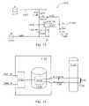
- FIG. 2is a schematic view of a fault protected relay 200 in accordance with an embodiment of the present invention.
- the fault protected relay 200includes a fault detection circuit 210 , a fault indicator circuit 220 , a power supply 230 and a relay 240 .
- a control line 252is coupled to the fault protected relay 200 that carries a control signal to the fault protected relay.
- An output 256 of the fault protected relay 200is coupled to a load (not shown).
- the fault detection circuit 210is coupled to the fault indicator circuit 220 and the relay 240 .
- the relay 240is also coupled to the fault indicator circuit 220 .
- the power supply 230is coupled to the control line 252 carrying the control signal, the ground 255 , and the fault indicator circuit 220 .
- the fault protected relay 200operates similarly to the relay 105 of FIG. 1 and controls the flow of power from a power source to a load using the relay 240 .
- the relay 240receives an external control signal via the fault indicator circuit 220 .
- the current flowing through the relayis monitored by the fault detection circuit 210 which provides a signal indicative of the fault status via output 253 to the fault indicator circuit 220 .
- the fault indicator circuit 220When a fault is detected, the fault indicator circuit 220 generates a control signal that inhibits relay 240 from providing power to the load.
- the fault indicator circuit 220controls the operation of the relay 240 by opening or closing a current loop that energizes the relay coil.
- the fault indicator circuitis configured to receive a signal indicative of a fault from the fault detection circuit. Depending on the absence or presence of a fault, the fault indicator circuit completes or interrupts the current loop. In several embodiments, the fault indicator circuit completes the current loop in the absence of a fault.
- the external control signal 252also controls the operation of relay. The external control signal can be generated in response to a pilot attempting to turn on an electrical component of the aircraft that is being controlled by the relay. Upon detection of a fault, the fault indicator circuit interrupts the current loop.
- the fault indicator circuitprovides a predetermined control signal as a substitute for the external control signal.
- the fault indicator circuitcontinues to provide the predetermined control output signal until it receives reset instructions.
- the reset signal 254can be provided by a maintenance person that has verified that the relay circuit is ready for safe operation. In one embodiment, the reset signal is provided by another circuit.
- the power supply 230provides power to the components used in the fault indicator circuit 220 .
- the power supplyreceives a relatively small amount of current from the external control signal 252 and provides that power to the fault indicator circuit.
- the relay 240 and the fault detection circuit 210can be implemented using any type of commercially available or specifically designed circuitry in accordance with known principles. Circuitry that can be used to implement a fault indicator circuit in accordance with embodiments of the invention are discussed below.
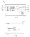
- FIG. 3is a schematic view of a fault indicator circuit 320 in accordance with an embodiment of the present invention.
- the fault indicator circuit 320includes an input logic circuit 322 , a nonvolatile memory element 324 , and a driving circuit 326 coupled together in series.
- the fault indicator circuitalso includes a switch 328 and a visual indicator 329 that are both coupled to the driving circuit 326 .
- Fault 350 and reset 354 inputs to the fault indicator circuitare provided to the input logic circuit 322 .
- a control input 352 and a control output 356 of the fault indicator switchare connected to the switch 328 .
- the fault indicator circuit 320is configured to receive a fault signal from the fault input 350 , a reset signal from the reset input 354 , and a control-in signal from a control input 352 and to output a control-out signal via a control output 356 . Depending on the values of the input signals the fault indicator circuit 320 can determine that a fault is present, visually indicate the existence of such fault, and/or open the relay. These operations are described in further detail below.
- the input logic circuit 322is coupled to lines that provide reset and fault signals.
- the fault signalis indicative of the existence of a present fault.
- the reset input 354provides a reset signal that indicates that the memory of the fault indicator circuit 320 should be cleared of any record indicative of a previous fault.
- the input logic circuit 322uses these signals to determine whether or not a present fault is being reported and whether a past fault should remain or be cleared in the memory.
- the output of the input logic circuit 322is provided to the nonvolatile memory element 324 which is configured to provide signals indicative of the fault status of the system.
- the nonvolatile memory element 324stores the fault status of the system and responds to signals received from the input logic circuit 322 .
- the nonvolatile character of the nonvolatile memory elementpermits this element to maintain the fault status in the absence of power.
- the nonvolatile memory element 324continues to indicate the existence of the fault to the downstream elements of the fault indicator circuit 320 .
- the fault status stored in the nonvolatile memory elementis determined by signals received by the input logic circuit 322 . If the input logic circuit indicates to the nonvolatile memory element that a fault saved in the memory should be reset, then the nonvolatile memory element clears any saved fault. The no-fault status is maintained and communicated to the down-stream elements of the fault indicator circuit 320 until the input logic circuit 322 subsequently indicates that a fault has been detected.
- the driving circuit 326receives a signal indicating the presence or absence of a fault from the nonvolatile memory element 324 . This signal can represent a present fault or a former unresolved fault.
- the driving circuit 326responds to the existence of a fault by providing an input to the switch 328 that prevents the control input signal from being provided on the control output line.
- the driving circuitindicates the existence of the fault by activating the visual indicator 329 .
- the receipt of a reset input by the fault indicator circuit 320results in the driving circuit 326 deactivating the visual indicator and closing the switch 328 to pass the signal on the control input line to the control output line.
- the visual indicatoris manually reset.
- the reset inputis provided to the fault indicator circuit 320 when the visual indicator is manually reset.
- the switch 328is turned on and off based on the signal received from the driving circuit 326 .
- the switch 328is coupled to control lines that carry a control-in signal to the switch and a control-out signal from the switch.
- the switch 328is configured to open or close a circuit between the control input 352 and the control output 356 . In short, the switch can interrupt the control signal.
- the control outputis connected to the control input of a relay, the absence of the control signal can cause the relay to open and prevent the flow of current from the source to the load.
- the visual indicator 329can be activated and deactivated by signals received from the driving circuit 326 .
- the nonvolatile memory elementstores the fault, and the output of the driving circuit 326 activates the visual indicator to indicate the existence of a fault to an operator.
- the driving circuit 326operates both the switch 328 and the visual indicator 329 concurrently. As such, if the driving circuit 326 receives an indication of a fault from the nonvolatile memory, the driving circuit drives the switch open and concurrently drives the visual indicator to show the existence of the fault to a human operator.
- the driving circuitdeactivates the visual indicator when a reset signal is received by the input logic circuit.
- the visual indicatorhas to be manually reset by an operator.
- the input logic circuit 322can be implemented using a combination of devices such as logic gates. Filter elements and switches can also be included in the logic circuit 322 .
- the nonvolatile memory element 324can be implemented using a variety of one-bit nonvolatile memory elements.
- One embodiment of the present inventionuses a potentiometer as the nonvolatile memory element 324 .
- the potentiometercan be a digital potentiometer.
- the driving circuit 326can be implemented using devices such as transistors and logic gates.
- the switch 328can be implemented using devices such as transistors and filters.
- the visual indicator 329can be implemented using a transistor or another type of switch that is coupled to a LED or an electromechanical pop-up indicator.
- Elements of the fault indicator circuitcan include filter components for filtering out noise such as higher frequency currents.
- components of the fault indicator circuitare implemented using an appropriately configured microprocessor, gate array or application specific integrated circuit (ASIC).
- FIG. 4is a schematic view of a power supply 430 that can be used to provide power to the fault indicator circuit in accordance with an embodiment of the present invention.
- the power supply 430is coupled between a control line and a ground.
- the control line and the ground that are coupled to the power supplyare also coupled to other elements such as a fault indicator circuit.
- at least one outgoing line from the power supplycan be used to provide a voltage signal.
- the power supplyutilizes a portion of the current flowing in the control line and converts this current into stable voltage signals.
- the voltage signals generated by the power supplycan be used to drive various components of the fault indicator circuit.
- a supply voltage Vccis generated by the power supply 430 that can be used by devices in the fault indicator circuit.
- the value of Vccis 5V. In other embodiments, other output voltage are provided.
- a power supply 430 in accordance with embodiments of the invention,can be implemented using any type of commercially available power supply or known power supply circuit configuration.
- FIG. 5is a flow chart showing a method of controlling the operation of a relay in response to the detection of a fault in accordance with an embodiment of the present invention.
- the method 500includes determining ( 510 ) if a present fault has been detected. If a present fault has been detected, a memory of the existence of the fault is stored ( 520 ) and a relay is opened ( 530 ). If it is determined ( 510 ) that no present fault has been detected, then a determination ( 540 ) is made as to whether or not a previous fault existed. If no present fault is detected and no previous fault existed, then the memory is reset (or cleared) ( 550 ) and the relay is allowed ( 560 ) to perform normal operations.
- a further determination ( 570 )is made as to whether or not the previous fault had been remedied. If the fault had not been remedied ( 570 ), a memory of the existence of the fault is maintained ( 520 ) and the relay is opened ( 530 ). If, on the other hand, the fault is determined to have been remedied ( 570 ), then the memory is reset ( 550 ) and the relay is allowed to operate normally ( 560 ). To check continuously for fault or reset, after opening the relay ( 530 ) or allowing normal operation ( 560 ), the method loops back to determining ( 510 ) whether a present fault has been detected.
- a decision tablecan be used to demonstrate the method of controlling the operation of a relay in accordance with the embodiment of the FIG. 5 .
- Table 1illustrated below, shows inputs and outputs to a fault indicator circuit in accordance with an embodiment of the invention.
- the input variablesinclude the fault status, the current memory state, and the reset signal.
- the output variablesinclude the next state of the memory, and the open or closed status of a switch that provides power to the relay.
- the output of switchis an inverted version of the memory output.
- the switchwill be closed and the relay will be permitted to convey power to the load.
- the third rowthere is no present fault but there is a stored fault and no reset. Therefore, the stored fault is maintained and the switch is open.
- the fourth rowthere is no present fault, a stored fault, and a reset request. Therefore, the memory is cleared to show a no-fault situation and the switch is closed.
- a present faultis detected. Therefore, irrespective of the previous status of memory or reset, the memory will show the existence of a fault and the switch is opened.
- a fault detection circuitcan be used to detect the presence of a fault in a relay device and a fault indicator circuit can be used to store the fault.
- a nonvolatile memory elementcan be used to maintain memory of a fault in the absence of power.
- One possible choice for a nonvolatile memory elementis a potentiometer including a nonvolatile memory.
- the potentiometercan be a digital potentiometer.
- the resistance of a potentiometercan be varied in response to a control signal and stored within the potentiometer's nonvolatile memory. Existence of a fault can be set to correspond to one resistance value and absence of fault can be set to correspond to another resistance value. In other embodiments, other types of nonvolatile memory elements are used.
- an EEPROMis used as a nonvolatile memory element.
- a logic circuitcan be used to provide appropriate inputs to a nonvolatile memory element in response to fault and reset inputs to the logic circuit.
- the nature of the logic circuitdepends on the nature of the nonvolatile memory element. For example, if a potentiometer is used as the nonvolatile memory element, then the existence of a fault can generate an output from the logic circuit that pushes the potentiometer to a high resistance value. Receipt of a reset signal can cause the logic circuit to generate an output that sets the potentiometer to a low resistance valve.
- FIG. 6is a schematic view of an input logic circuit 622 and a nonvolatile memory element 624 that can be used in a fault indicator circuit in accordance with an embodiment of the present invention.
- the nature of the input logic circuit 622depends upon the nature of the nonvolatile memory element 624 .
- the nonvolatile memory element 624is a digital potentiometer having a memory and a counter.
- the potentiometerhas three inputs including signals indicating whether the potentiometer device is selected, (active low chip select whether the counter should count up (high) or down (low), and whether to increment the counter active low increment.
- the increment counter signaloften appears as a “pulse train”. The potentiometer can be changed only when the device is selected.
- the counterwill count up or down depending on the state of up/down signal.
- the memorymaintains the counter value at the end of the pulse train. This value is stored until the device is selected again and another pulse train is received. In several embodiments, a high count is used to indicate a fault and a low count is used to indicate no fault.
- the logic circuit 622is configured to respond to fault and reset input signals by generating inputs to the potentiometer that cause the potentiometer to store appropriate information.
- the input logic circuituses fault and reset inputs to generate a device select signal, a count up/down signal, and a pulse train.
- the nonvolatile memoryhas different inputs and the input logic circuit generates appropriate signals to supply those inputs.
- the nonvolatile memory element 624is implemented using an IntersilTM X9315 digitally controlled potentiometer manufactured by Intersil Americas, Inc., of Milpitas, Calif. Specifications and principles of operation of this potentiometer are described in data sheet FN8179.1, dated Sep. 15, 2005, that is incorporated into the present application by reference.
- IntersilTM potentiometeralso includes a counter and a nonvolatile memory.
- the IntersilTM potentiometerincludes first, second, and third input terminals 1 , 2 , 7 and an output terminal 5 . While not shown, the nonvolatile memory element 624 can also include terminals that are connected to Vcc and Vss operating voltages.
- the IntersilTM potentiometeroperates generally in the manner outlined above.
- An increment signalis provided at the input terminal 1 , an up/down signal at the input terminal 2 , and a device select signal at the input terminal 7 .
- the increment signalcontrols the incrementing or decrementing of the digital potentiometer.
- the up/down signalindicates whether the resistance of the nonvolatile memory element should be increased, to indicate a fault, or be decreased to indicate no fault, or vice versa.
- the device select signalenables operation of the potentiometer.
- the value of the counteris stored in nonvolatile memory whenever the device is deselected. This occurs when the active low device select signal transitions to high and the increment signal is also high.
- the input logic circuit 622generates the inputs necessary to store and clear fault information using the IntersilTM X9315 digitally controlled potentiometer.
- the input logic circuit 622includes two inputs ( 602 , 603 ), three outputs ( 631 , 632 , 633 ), NOR gate 601 , NAND gates ( 611 , 612 , 613 , 614 ), inverter 605 , and delay elements ( 604 , 606 , 607 ).
- Inputs 602 and 603are coupled to the inputs of NOR gate 601 and to the reset and fault input signals, respectively.
- Input 602is also coupled to output 632 , which is coupled pin 2 (up/down input that counts down when low) of the digital potentiometer 624 .
- the output of NOR gate 601is coupled to both inputs of NAND 611 (effectively acting as an inverter).
- the output of NAND 611(node A) is coupled to one input of NAND 612 .
- the output of NAND 612is coupled to the second input of NAND 612 (i.e. feedback) via delay element 604 and to the first input of NAND 613 .
- the output of NAND 613is coupled to output 631 which is coupled to pin 1 (active low increment input) of digital potentiometer 624 .
- Node Ais also coupled to delay element 606 which is coupled to inverter 605 .
- the output of inverter 605is coupled to the second input of NAND 613 and to delay element 607 .
- the output of delay element 607is coupled to the first input of NAND 614 .
- the node Ais also coupled to the second input of NAND 614 .
- the output of NAND 614is coupled to output 633 , which is coupled to pin 7 active low (chip or device select) of digital potentiometer 624 .
- node Ais logical combination of the reset signal (R) and fault signal (F) inputs equivalent to “R+F” (i.e. R OR F).
- R+Ffault signal
- node Ais low. If node A is low, the output of NAND 612 will be a steady state high, and the output of inverter 605 will also be a steady state high. So during steady state operation as defined by an absence of a fault or reset (i.e. node A is low), the output of NAND 613 will be low along with output 631 and pin 1 (active low increment input) of digital potentiometer 624 .
- node Atransitions from low to high. Since the output of NAND 612 was previously high for steady state operation, the output of delay element 604 is high. Then the output of NAND 612 becomes low as both inputs are high. After a delay, the output of delay element 604 becomes low and consequently the output of NAND 612 becomes high again. Thus, after node A transitions from low to high, the output of NAND 612 oscillates with a frequency that depends on the duration of the delay provided by delay element 604 . In one embodiment, the frequency of the oscillating output of NAND 612 (similar to a clock) is twice the duration of the delay of delay element 604 .
- the output of inverter 605becomes low after the delay caused by delay element 606 .
- the output of NAND 613becomes an inverted version of the oscillating output (clock) of NAND 612 .
- the output of inverter 605becomes low and consequently, the output of NAND 613 (increment signal) stays high.
- the output of delay element 607is high and the output of NAND 614 is high.
- the output of NAND 614becomes low and remains low for the duration of delays from both delay elements 606 and 607 .
- the output of delay element 607becomes low and thus the output of NAND 614 goes high again.
- an active low pulseis provided by the output of NAND 614 as a chip or device select. The duration of the active low chip select pulse is determined by the addition of the delays caused by delay element 606 and delay element 607 .
- FIG. 7illustrates a timing diagram indicative of the operation of the input logic circuit and nonvolatile memory element of FIG. 6 during a fault. From top to bottom the diagram illustrates inputs signals reset ( 602 ) and fault ( 603 ), node A (R+F), outputs of NAND gates 612 , 613 , 614 , and the output of the digital potentiometer 624 at pin 5 . As discussed above, for steady state operation where reset and fault are low, node A is low, the output of NAND 612 is high, the output of NAND 13 is low, and the output of NAND 14 is high. The output of the digital potentiometer (pin 5 ) is indicative of no fault, where the internal resistance of the potentiometer and corresponding output voltage at steady state is sufficiently high to supply the driving circuit 326 (see FIG. 3 ).
- NAND 612begins oscillating with a period determined by delay element 604
- NAND 13input to active low increment input of digital potentiometer 624
- NAND 614outputs an inverted version of NAND 612 for a duration determined by delay elements 606 and 607
- digital potentiometer 624decreases internal resistance and corresponding output voltage at pin 5 on every falling edge of the increment signal while the chip select signal is low.
- the signal trace for pin 5 illustrated in FIG. 7shows four such transitions resulting in decreasing output voltage.
- the digital potentiometer 624stores the value of the output voltage at pin 5 , in effect by storing the resistance setting of the potentiometer, on the rising edge of the chip select signal while the increment signal is high such that the value is not lost when the digital potentiometer loses power. If a reset occurs subsequent to the occurrence of a fault, but before the fault has been cleared, the reset has no effect on the output of the digital potentiometer, as illustrated in FIG. 7 .
- the operation of the input logic circuit and nonvolatile memoryare consistent with Table 1 shown above.
- FIG. 8is a timing diagram illustrating the operation of the input logic circuit and nonvolatile memory element of FIG. 6 to clear a fault in response to a reset. From top to bottom the diagram illustrates inputs signals reset ( 602 ) and fault ( 603 ), node A (R+F), outputs of NAND gates 612 , 613 , 614 , and the output of the digital potentiometer 624 at pin 5 . As discussed above, for steady state operation where reset and fault are low, node A is low, the output of NAND 612 is high, the output of NAND 13 is low, and the output of NAND 14 is high. The output of the digital potentiometer (pin 5 ) is indicative of a prior fault, where the internal resistance of the potentiometer and corresponding output voltage at steady state is low compared to the initial default position (see FIG. 7 ).
- the input logic circuitfunctions as described above for FIG. 7 indicating a fault except that the up/down signal (reset) instructs the digital potentiometer to increase the output voltage at pin 5 as illustrated.
- the digital potentiometer 624again stores the value of the output voltage at pin 5 , in effect by storing the resistance setting of the potentiometer, on the rising edge of the chip select signal while the increment signal is high.
- the digital potentiometeris storing a high value indicating no fault, effectively having cleared the existing fault.
- the duration of delay element 606is set such that a predetermined integer number of oscillations are delivered to the active low increment input of digital potentiometer 624 .
- the predetermined integer number of oscillationsis equal to or exceeds a maximum counter value for the digital potentiometer.
- oscillations created by delay element 604occur at a frequency of 71 KHz, the period of delay for delay element 606 is 10 ms, and the period of delay for delay element 607 is 0.1 ms.
- the various logic gates used in the input logic circuit 622can be implemented commercially available NOR, NAND, and NOT gates.
- the NOR gatecan be implemented using a Philips SemiconductorTM 74LVC1G57 low power configurable multiple function gate manufactured by Philips Semiconductor, Inc., of Washington, D.C.
- the NAND gatescan be implemented using a Texas InstrumentTM SN74LVC2G132, dual 2-input NAND gate with Schmitt-Trigger inputs, manufactured by Texas Instruments, Inc., of Dallas, Tex.
- the NOT gatecan be implemented using a Philips SemiconductorTM 74LVC3G14 triple inverting Schmitt trigger with 5V tolerant input.
- the period of delay for delay element 604can be generated using an RC circuit of 20 K ⁇ of resistance and 500 pF of capacitance.
- the delay for delay element 606can be implemented using an RC circuit of 49.9 K ⁇ of resistance and 0.1 ⁇ F of capacitance at 10V.
- the delay for delay element 607can be implemented using an RC circuit of 100 K ⁇ of resistance and 0.01 ⁇ F of capacitance at 10V.
- an input logic circuit having reset and fault input signalsworks in conjunction with a digital potentiometer to store and clear fault conditions.
- other digital potentiometers or conventional non-digital potentiometers having memorycan be used.
- an input logic circuitcan be used in conjunction with an EEPROM or other nonvolatile memory device.
- a flip-flop type componentcan be used as the nonvolatile memory element in conjunction with a suitable input logic circuit.
- the flip-flop type or one bit non-volatile memory componentis implemented in an ASIC.
- the flip-flop type componentis implemented in a programmable logic device.
- both the input logic circuit and flip-flop type componentare implemented using a programmable logic device (i.e. PLD, CPLD, FPGA) and/or an ASIC.
- FIG. 9is a schematic view of a driving circuit 726 for use in a fault indicator circuit in accordance with an embodiment of the present invention.
- the driving circuit 726includes two inverters that are coupled together in series.
- the driving circuit 726includes one input and two outputs.
- the inputprovides a low or a high signal to the driving circuit 726 .
- the low signalcan be used to communicate the absence of a fault and the high signal can be used to communicate the presence of a fault or vice versa.
- the input signal and an inverted version of the input signalare provided as output signals to both the switch 328 and visual indicator 329 .
- the invertersare Philips SemiconductorTM 74LVC3G14 triple inverting Schmitt trigger inverters with 5V tolerant inputs.
- NAND gatesconfigured as inverters can be used.
- other suitable inverterscan be used.
- FIG. 10is a schematic view of a relay control switch 828 for use in a fault indicator circuit in accordance with an embodiment of the present invention.
- the relay control switch 828includes an NMOS transistor 830 and a PMOS transistor 831 coupled together in a drain to gate configuration.
- a resistor R 8couples the drain of the NMOS transistor 830 to the source of the PMOS transistor 831 .
- Other componentssuch as additional resistors and filter components can be included in other embodiments.
- the relay control switch 828includes two input terminals and one output terminal.
- the first input signalcorresponds to the on/off signal provided by the driving circuit.
- the first input signalis provided to the gate of the transistor 830 and can turn transistor 830 off or on.
- transistor 830is on, the drain current of the transistor 830 provides suitable switching voltage to the gate of the second transistor 831 which turns the second transistor on or off.
- the second input signalcan be an external control signal that can be used to control a relay.
- the external control signalis received at the source of transistor 831 .
- the second transistor 831is on, it closes a circuit carrying a current corresponding to the external control signal from the control input to the control output of the relay control switch 828 .
- the control input signalalso provides drain voltage for transistor 830 .
- the relay control switchcan be implemented using a different arrangement of NMOS transistors or PMOS transistors. In other embodiments, electromechanical switches can be used instead of transistors.
- the first transistoris implemented using a Fairchild SemiconductorTM 2N7002 N-channel enhancement mode FET DMOS transistor manufactured by Fairchild Semiconductor, Inc., of South Portland, Me., and the second transistor is a Philips SemiconductorTM BSH 202 P-channel enhancement mode MOS transistor.
- FIG. 11is a schematic view of a visual indicator circuit 929 that includes an electronic visual indicator for use in a fault indicator circuit in accordance with an embodiment of the present invention.
- the visual indicator circuit 929includes an NMOS transistor coupled to a light emitting diode (LED).
- the drain of the NMOS transistoris coupled to a cathode electrode of the LED.
- the source of the NMOSis grounded.
- An anode electrode of the LEDis coupled to a power supply.
- a resistor R 9is coupled between the power supply and the anode electrode of the LED.
- a PMOS transistorcan be used instead with the source coupled to the LED.
- Another type of switchcan also be used instead of the NMOS transistor.
- the visual indicator circuitcan include other components such as resistors or filters.
- An input signal from the driving circuitis provided to the visual indicator at the gate of the transistor.
- a high input signalturns the NMOS transistor on. When the transistor is on, it allows current from the power supply to flow through the LED which emits light. The LED provides a visual indication of a fault.
- the switch used in the visual indicatorcan be implemented using NMOS transistors, PMOS transistors, or electromechanical switches.
- the transistorcan be implemented as a Fairchild SemiconductorTM 2N7002 N-channel enhancement mode FET DMOS transistor or a Philips SemiconductorTM BSH 202 P-channel enhancement mode MOS transistor.
- other types of switches suitable to drive the LEDare used.
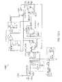
- FIG. 12is a circuit diagram of a fault indicator circuit 1000 in accordance with an embodiment of the present invention.
- the fault indicator circuit 1000includes sub-circuits that correspond to the input logic circuit and nonvolatile memory element of FIG. 6 , the driving circuit of FIG. 7 , the relay control switch of FIG. 8 , and the visual indicator of FIG. 9 . These sub-circuits can operate as described above for each respective sub-circuit.
- a number of parallel RC filtersare included that filter the high frequency part of input signals and prevent it from interacting with the remainder of the fault indicator circuit 1000 .
- a number of series RC componentsare used as delay elements.
- a reset switch 1002provides a reset signal to the fault indicator circuit 1000 when the switch is closed.
- the reset signalis provided by a high voltage level from the power supply 1001 .
- the power supplyprovides 5V to the fault indicator circuit 1000 input when the reset switch 1002 is closed.
- the input 1005provides a fault signal to the fault indicator circuit 1000 .
- the fault signalcan be generated anywhere in the electrical system of the airplane and is provided to the fault indicator circuit 1000 via the input 1005 .
- FIG. 13is a circuit diagram of a power supply assembly 1400 that can be used to provide power to a fault indicator circuit in accordance with an embodiment of the present invention.
- the power supply assembly 1400includes a control line 1401 coupled to a power supply 1430 through a resistor 1431 .
- the power supply 1430is grounded through a first bypass capacitor 1432 , that is coupled to an input 1402 of the power supply 1430 , and through a second bypass capacitor 1434 that is coupled to an output 1403 of the power supply 1430 .
- the power supply 1430has two other terminals that are both also grounded.
- a diode 1435is coupled across the input 1402 and output 1403 terminals of the power supply 1435 .
- the power supply assembly 1400as a whole, receives one input from a control line 1401 and is also connected to a ground.
- the power supply assembly 1400has one output 1403 .
- the power supply 1430receives a small amount of current from the control line 1401 and provides a stable supply of power, through its output 1403 , to various elements of the fault indicator circuit 1000 .
- the diode 1435prevents direct current flow from the control line 1401 to the output 1403 of the power supply but permits a reverse flow of current.
- the first and second bypass capacitors 1432 , 1434filter out the high frequency components of the current and voltage to prevent damage to the power supply 1430 .
- the control line 1401carries 15V and the power supply assembly 1430 uses current sufficient to generate a stable supply voltage of 5V at the output 1403 .
- the supply voltagecan be provided as the Vcc signal to various transistors and other components of the fault indicator circuit 1000 .
- the control linecan provide an AC voltage and the power supply would be configured accordingly.
- a micro-power small outline transistoris used to implement power supply 1430 .
- Linear TechnologyTM LT1790 micropower SOT-23 low dropout reference power supplymanufactured by Linear Technology, Inc., of Milpitas, Calif.
- the diodecan be implemented using a high conductance fast diode for example 1N4148 from Fairchild SemiconductorTM.
- the first bypass capacitor 1432at the input, can be implemented using a 0.1 ⁇ F capacitor (25 V).
- the second bypass capacitor 1434at the output, can be implemented using a 1 ⁇ F capacitor (10 V).
- the resistorcan be a 2.43 K ⁇ resistor.
- FIG. 14is a schematic view of a fault indicator circuit including electromagnetic shielding in accordance with an embodiment of the present invention.
- the fault indicator circuit 1100is coupled to the coil of a relay 1110 that is in turn coupled to a load 1120 .
- the fault indicator circuit 1100includes an input logic circuit 1103 , an electromechanical switch 1105 and an electromagnetic shield 1140 .
- the fault indicator circuit 1100receives a fault signal and a control-in signal and generates a control-out signal.
- the input logic circuit 1103receives the fault signal and the reset signal and controls the electromechanical switch 1105 within the fault indicator circuit 1100 .
- the input logic circuittrips the electromechanical switch 1105 when the fault signal indicates the existence of a fault.
- the electromechanical switch 105opens the current loop that provides current to the relay 1110 .
- the electromechanical switchacts as a nonvolatile memory and maintains the memory of this fault by maintaining the state of the fault indicator circuit until it is reset.
- the reset signal or stimulusis also provided to the fault indicator circuit 1100 .
- the electromechanical switchcontrols the relay by interrupting (i.e. disconnecting) the external control signal that controls the relay when appropriate.
- Reset of the fault indicator circuit 1100clears the fault and instructs the electromechanical switch 1105 to allow the control signal to pass through.
- the reset signalclears a past fault while the fault signal indicates a present fault.
- the reset signalis provided by a switch.
- the switchis part of a pop-up fault indicator. In other embodiments, the switch is separate from any fault indicating circuitry.
- Electromechanical switchescan be inadvertently tripped as influenced by electromagnetic fields such as those generated by the relay coil.
- the electromagnetic shield 1140in accordance with the embodiments of the invention, reduces the potential for electromagnetic fields to interfere with the operation of the electromechanical switch inside the fault indicator circuit 1100 .
- the fault indicator circuit 1100 and the relay 1110can be implemented using a variety of commercially available products.
- the electromagnetic shield 1140can be implemented using any type of material that interacts with and absorbs or disrupts the electromagnetic field. In one embodiment, metallic material is used for the electromagnetic shield.
- magnetic shieldsare formed utilizing ferrous alloys which have high magnetic permeability.
- ferrous alloyswhich have high magnetic permeability.
- Some examples of these materialsinclude cold rolled steel, low carbon steel, electric Iron, mild steel, silicon steel (SiFe), HyMu alloy referring to a generic class of alloys that have high magnetic permeability levels (mu).
- examples of some materials that can be used for implementing the magnetic shieldsinclude Supermalloy, Hymu 800, Silectron Z, Supermendur, Permalloy, Hy-Ra 80, Orthanol, Deltamax, Hypemik, and Mu-metal.
- the electromechanical switch 1105can be implemented using a Reed switch or a Reed relay.
- the Reed switchis an electrical switch that is operated by applying a magnetic field.
- the magnetic fieldcan be applied using a permanent magnet or by an electromagnet.
- One type of Reed switchincludes a pair of contacts made from magnetic material in a hermetically sealed glass envelope. The contacts can be normally open, which close when a magnetic field is present, or normally closed, which open when a magnetic field is applied.
- the Reed relaytypically includes one or more Reed switches that are controlled by an electromagnet.
- Reed switches and Reed relaysare formed such that they can be tripped using a magnetic field and do not need an actual mechanical or electrical triggering.
- the Reed switchis intended to be operated by its corresponding electromagnet.
- Reed switchesare vulnerable to parasitic magnetic fields that can be present in the atmosphere around the switch. Depending on the sensitivity of the Reed switch, various magnetic fields in the vicinity can interfere with the Reed switch and trip it when it is not intended to be tripped by the operating logic circuit.
- sensitivityis the amount of magnetic energy necessary to actuate the switch.
- sensitivityis measured in units of Ampere-turns, corresponding to the current in the coil multiplied by the number of turns.
- the electromagnetic shield used to protect the electromechanical switch from unintended trippingis selected to match the sensitivity of the electromechanical switch.
- a Reed switch with low sensitivityrequires a high magnetic field in order to be actuated, can be protected with a thin sheet of ferrous material.
- a highly sensitive Reed switchthat is easily tripped, requires a thicker shield that does not let through even small portions of the parasitic electromagnetic fields.
- FIG. 15 aillustrates a visual indicator and a manual reset mechanism to be used with a fault indicator circuit 1100 ′.
- the fault indicator circuit 1100 ′includes a pop-up indicator 1210 that can be a pop-up button.
- the fault signaltrips the electromechanical switch 1105 ′ within the fault indicator circuit 1100 ′.
- the electromechanical switchopens the current loop and pushes up the pop-up indicator 1210 from position 1220 to position 1230 (see FIG. 15B ).
- the pop-up indicator 1210 of the electromechanical switcheffectively maintains the memory of this fault in the up position ( 1230 ).
- pushing down the pop-up indicator from up-position 1230 back to down-position 1220resets the fault indicator circuit 1100 ′ and enables the electromechanical switch 1105 ′ to pass the control signal to the relay.
- the pop-up indicatorpops up in response to a fault and provides a visual indication of the fault while also serving as a nonvolatile memory of the fault until reset.
- the fault indicator circuitis manually reset when the pop-up indicator is pushed down.
- the electromechanical switchcan be manually reset using a different manual reset mechanism.
Landscapes
- Physics & Mathematics (AREA)
- Electromagnetism (AREA)
- General Physics & Mathematics (AREA)
- Emergency Protection Circuit Devices (AREA)
Abstract
Description
| TABLE 1 | |||||
| Input | Input | Input | Output | Output | |
| Fault | Memory | Memory | Switch | ||
| 0 | 0 | 0 | 0 | 1 | |
| 0 | 0 | 1 | 0 | 1 | |
| 0 | 1 | 0 | 1 | 0 | |
| 0 | 1 | 1 | 0 | 1 | |
| 1 | 0 | 0 | 1 | 0 | |
| 1 | 0 | 1 | 1 | 0 | |
| 1 | 1 | 0 | 1 | 0 | |
| 1 | 1 | 1 | 1 | 0 | |
Claims (20)
Priority Applications (1)
| Application Number | Priority Date | Filing Date | Title |
|---|---|---|---|
| US11/969,861US7738230B2 (en) | 2008-01-04 | 2008-01-04 | Nonvolatile status indicator switch |
Applications Claiming Priority (1)
| Application Number | Priority Date | Filing Date | Title |
|---|---|---|---|
| US11/969,861US7738230B2 (en) | 2008-01-04 | 2008-01-04 | Nonvolatile status indicator switch |
Publications (2)
| Publication Number | Publication Date |
|---|---|
| US20090174981A1 US20090174981A1 (en) | 2009-07-09 |
| US7738230B2true US7738230B2 (en) | 2010-06-15 |
Family
ID=40844363
Family Applications (1)
| Application Number | Title | Priority Date | Filing Date |
|---|---|---|---|
| US11/969,861Expired - Fee RelatedUS7738230B2 (en) | 2008-01-04 | 2008-01-04 | Nonvolatile status indicator switch |
Country Status (1)
| Country | Link |
|---|---|
| US (1) | US7738230B2 (en) |
Cited By (1)
| Publication number | Priority date | Publication date | Assignee | Title |
|---|---|---|---|---|
| US11605516B2 (en)* | 2018-06-18 | 2023-03-14 | Edward W. Anderson | Testable sealed relay and self-diagnosing relay |
Families Citing this family (16)
| Publication number | Priority date | Publication date | Assignee | Title |
|---|---|---|---|---|
| US8460284B2 (en) | 2007-10-26 | 2013-06-11 | Encision, Inc. | Multiple parameter fault detection in electrosurgical instrument shields |
| US8453674B2 (en)* | 2010-03-12 | 2013-06-04 | Target Rock Division Of Curtiss-Wright Flow Control Corporation | Valve fault indication and control |
| JP2012138890A (en)* | 2010-12-10 | 2012-07-19 | Nippon Dempa Kogyo Co Ltd | Piezoelectric oscillator |
| DE102011052810A1 (en)* | 2011-08-18 | 2013-02-21 | Phoenix Contact Gmbh & Co. Kg | SAFETY SWITCHING DEVICE |
| US8719660B2 (en) | 2011-12-20 | 2014-05-06 | Sandisk Technologies Inc. | Apparatus and methods for indicating the health of removable storage devices |
| US9869997B2 (en)* | 2013-02-15 | 2018-01-16 | General Electric Company | Protection monitoring system with fault indicators |
| US9547032B2 (en) | 2013-08-29 | 2017-01-17 | Intermountain Electronics, Inc. | Frequency hopping ground monitor current sensing |
| US9541596B2 (en) | 2013-08-29 | 2017-01-10 | Intermountain Electronics, Inc. | Multi-frequency ground monitor current sensing without a DC component |
| US9645184B2 (en)* | 2013-08-29 | 2017-05-09 | Intermountain Electronics, Inc. | Watchdog circuit for ground monitor current sensing |
| US9541595B2 (en) | 2013-08-29 | 2017-01-10 | Intermountain Electronics, Inc. | Multi-frequency ground monitor current sensing |
| CN105393178B (en)* | 2014-04-25 | 2017-05-24 | 三菱电机株式会社 | Programmable logic controller |
| FR3032795A1 (en)* | 2015-02-17 | 2016-08-19 | Eco Gtb | CO2 SENSOR ON BATTERY WITH ANALOGUE OUTPUT IN OHMIC VALUE FOR BUILDING TECHNICAL MANAGEMENT SYSTEM |
| US20180145497A1 (en)* | 2016-11-23 | 2018-05-24 | Schneider Electric USA, Inc. | Method to utilize multiple configuration software for df/cafi breakers |
| KR102617729B1 (en)* | 2018-09-17 | 2023-12-26 | 삼성에스디아이 주식회사 | Device for maintaining the operating state of a relay and electronic device including the device |
| US11506692B2 (en)* | 2020-09-17 | 2022-11-22 | Automatic Timing & Controls, Inc. | Ultra-low leakage test verification circuit |
| CN118969559B (en)* | 2024-07-23 | 2025-09-30 | 珠海派诺科技股份有限公司 | Independent latch switch high voltage control method and electronic device |
Citations (9)
| Publication number | Priority date | Publication date | Assignee | Title |
|---|---|---|---|---|
| US3614533A (en)* | 1970-05-20 | 1971-10-19 | Rucker Co | Ground fault detector and circuit interrupter by magnetic flux storage method |
| US20040070897A1 (en) | 2002-10-09 | 2004-04-15 | Zhixin Wu | Ground fault circuit interrupter with reverse wiring protection |
| US20040145840A1 (en) | 2000-06-26 | 2004-07-29 | Premier Aviation, Inc. | Method and apparatus for detecting electrical faults and isolating power source from the electrical faults |
| US20050018371A1 (en)* | 2003-06-13 | 2005-01-27 | Mladenik John E. | Systems and methods for fault-based power signal interruption |
| US20050083617A1 (en) | 2003-10-20 | 2005-04-21 | The Boeing Company | Ground and line fault interrupt controller/adapter |
| US20050286184A1 (en) | 2004-06-22 | 2005-12-29 | Steve Campolo | Electrical power outlet strip |
| US7007179B2 (en)* | 2001-02-08 | 2006-02-28 | Honeywell International Inc. | Electric load management center |
| US20070201170A1 (en) | 2006-02-28 | 2007-08-30 | Hooper William P | Devices, systems, and methods for providing electrical power |
| US20070291428A1 (en) | 2001-02-01 | 2007-12-20 | Hydro-Aire, Inc. | Aircraft applicable circuit imbalance detection and circuit interrupter and packaging thereof |
- 2008
- 2008-01-04USUS11/969,861patent/US7738230B2/ennot_activeExpired - Fee Related
Patent Citations (9)
| Publication number | Priority date | Publication date | Assignee | Title |
|---|---|---|---|---|
| US3614533A (en)* | 1970-05-20 | 1971-10-19 | Rucker Co | Ground fault detector and circuit interrupter by magnetic flux storage method |
| US20040145840A1 (en) | 2000-06-26 | 2004-07-29 | Premier Aviation, Inc. | Method and apparatus for detecting electrical faults and isolating power source from the electrical faults |
| US20070291428A1 (en) | 2001-02-01 | 2007-12-20 | Hydro-Aire, Inc. | Aircraft applicable circuit imbalance detection and circuit interrupter and packaging thereof |
| US7007179B2 (en)* | 2001-02-08 | 2006-02-28 | Honeywell International Inc. | Electric load management center |
| US20040070897A1 (en) | 2002-10-09 | 2004-04-15 | Zhixin Wu | Ground fault circuit interrupter with reverse wiring protection |
| US20050018371A1 (en)* | 2003-06-13 | 2005-01-27 | Mladenik John E. | Systems and methods for fault-based power signal interruption |
| US20050083617A1 (en) | 2003-10-20 | 2005-04-21 | The Boeing Company | Ground and line fault interrupt controller/adapter |
| US20050286184A1 (en) | 2004-06-22 | 2005-12-29 | Steve Campolo | Electrical power outlet strip |
| US20070201170A1 (en) | 2006-02-28 | 2007-08-30 | Hooper William P | Devices, systems, and methods for providing electrical power |
Non-Patent Citations (3)
| Title |
|---|
| International Search Report for Application No. PCT/US08/50321 filed Jan. 4, 2008, dated Jun. 14, 2008, mailed Jun. 27, 2008, 2 pages. |
| Ramtron International Corporation; "FM 1105: Nonvolatile 5V Dual State Saver" Data Sheet Rev. 1.0 May 2007, pp. 1-8. |
| Written Opinion for Application No. PCT/US08/50321 filed Jan. 4, 2008, dated Jun. 20, 2008, mailed Jun. 27, 2008, 5 pages. |
Cited By (1)
| Publication number | Priority date | Publication date | Assignee | Title |
|---|---|---|---|---|
| US11605516B2 (en)* | 2018-06-18 | 2023-03-14 | Edward W. Anderson | Testable sealed relay and self-diagnosing relay |
Also Published As
| Publication number | Publication date |
|---|---|
| US20090174981A1 (en) | 2009-07-09 |
Similar Documents
| Publication | Publication Date | Title |
|---|---|---|
| US7738230B2 (en) | Nonvolatile status indicator switch | |
| EP2232660A1 (en) | Nonvolatile status indicator switch | |
| US7486492B2 (en) | Electrical switching apparatus including a second trip circuit responding to failure of a first trip circuit to provide a repetitive signal | |
| US6111733A (en) | Intelligent ground fault circuit interrupter | |
| US20140104068A1 (en) | Method And Structure For Monitoring Breaker Status Contacts On Circuit Breaker Applications | |
| US11165245B2 (en) | Overvoltage protector with array of resistors | |
| EP2202861A2 (en) | Method and apparatus for tripping circuit breaker | |
| US6587027B1 (en) | Solid state fuse | |
| KR100804520B1 (en) | Earth leakage blocking method and device for preventing leakage by detecting leakage current in two stages | |
| US10431972B2 (en) | Auto-monitoring circuit and circuit interrupter including the same | |
| HK1151393B (en) | An aircraft electronical system and method for controlling a relay therein | |
| EP2783381B1 (en) | A method and circuit for increasing the speed of an electromechanical output on a protective relay | |
| CA2957090C (en) | Circuit interrupter with audible indicator circuit | |
| US5875641A (en) | Contactor with solid state protection circuit for a vapor compression air conditioner | |
| JP5443430B2 (en) | Excitation power source for superconducting magnets | |
| CN104054152B (en) | For increasing method and the circuit of the speed of electromechanical protective relay | |
| JP2824027B2 (en) | Nuclear power plant safety protection equipment | |
| CA2115358A1 (en) | Trip energy monitor | |
| JPH04308414A (en) | Dc circuit protective device | |
| JPH06169524A (en) | Input device for make and break contact | |
| JPH11311645A (en) | Battery voltage detecting circuit | |
| JPS61109217A (en) | Static circuit breaker trip circuit | |
| MXPA06010126A (en) | Device and method for the extended protection of electric lines. | |
| HK1105248A (en) | Device and method for the extended protection of electric lines |
Legal Events
| Date | Code | Title | Description |
|---|---|---|---|
| AS | Assignment | Owner name:LEACH INTERNATIONAL CORPORATION, CALIFORNIA Free format text:ASSIGNMENT OF ASSIGNORS INTEREST;ASSIGNORS:KHAN, IMTIAZ;MALLON, ROBERT C.;REEL/FRAME:020419/0508 Effective date:20080104 Owner name:LEACH INTERNATIONAL CORPORATION,CALIFORNIA Free format text:ASSIGNMENT OF ASSIGNORS INTEREST;ASSIGNORS:KHAN, IMTIAZ;MALLON, ROBERT C.;REEL/FRAME:020419/0508 Effective date:20080104 | |
| CC | Certificate of correction | ||
| AS | Assignment | Owner name:WELLS FARGO BANK, NATIONAL ASSOCIATION, AS ADMINIS Free format text:SECURITY AGREEMENT;ASSIGNOR:LEACH INTERNATIONAL CORPORATION;REEL/FRAME:026104/0162 Effective date:20110311 | |
| FPAY | Fee payment | Year of fee payment:4 | |
| FEPP | Fee payment procedure | Free format text:MAINTENANCE FEE REMINDER MAILED (ORIGINAL EVENT CODE: REM.) | |
| LAPS | Lapse for failure to pay maintenance fees | Free format text:PATENT EXPIRED FOR FAILURE TO PAY MAINTENANCE FEES (ORIGINAL EVENT CODE: EXP.) | |
| STCH | Information on status: patent discontinuation | Free format text:PATENT EXPIRED DUE TO NONPAYMENT OF MAINTENANCE FEES UNDER 37 CFR 1.362 | |
| FP | Lapsed due to failure to pay maintenance fee | Effective date:20180615 | |
| FP | Lapsed due to failure to pay maintenance fee | Effective date:20180615 | |
| AS | Assignment | Owner name:LEACH INTERNATIONAL CORPORATION, CALIFORNIA Free format text:RELEASE BY SECURED PARTY;ASSIGNOR:WELLS FARGO BANK, NATIONAL ASSOCIATION AS ADMINISTRATIVE AGENT;REEL/FRAME:048605/0202 Effective date:20190314 | |
| AS | Assignment | Owner name:CREDIT SUISSE AG, NEW YORK Free format text:SECURITY INTEREST;ASSIGNORS:SOURIAU USA, INC.;LEACH INTERNATIONAL CORPORATION;TA AEROSPACE CO.;AND OTHERS;REEL/FRAME:048788/0719 Effective date:20190329 Owner name:THE BANK OF NEW YORK MELLON TRUST COMPANY, N.A., I Free format text:SECURITY INTEREST;ASSIGNORS:SOURIAU USA, INC.;LEACH INTERNATIONAL CORPORATION;TA AEROSPACE CO.;AND OTHERS;REEL/FRAME:048788/0581 Effective date:20190329 | |
| AS | Assignment | Owner name:THE BANK OF NEW YORK MELLON TRUST COMPANY, N.A., AS TRUSTEE AND NOTES COLLATERAL AGENT, ILLINOIS Free format text:PATENT SECURITY AGREEMENT;ASSIGNORS:AIRBORNE SYSTEMS NORTH AMERICA OF NJ INC.;ACME AEROSPACE, INC.;ADAMS RITE AEROSPACE, INC.;AND OTHERS;REEL/FRAME:052352/0704 Effective date:20200408 | |
| AS | Assignment | Owner name:THE BANK OF NEW YORK MELLON TRUST COMPANY, N.A., AS TRUSTEE, ILLINOIS Free format text:SECURITY INTEREST;ASSIGNORS:TRANSDIGM INC.;TRANSDIGM GROUP INCORPORATED;17111 WATERVIEW PKWY LLC;AND OTHERS;REEL/FRAME:063012/0788 Effective date:20230224 | |
| AS | Assignment | Owner name:APICAL INDUSTRIES, INC., OHIO Free format text:RELEASE BY SECURED PARTY;ASSIGNOR:THE BANK OF NEW YORK MELLON TRUST COMPANY, N.A., AS TRUSTEE;REEL/FRAME:063363/0753 Effective date:20230410 Owner name:SIMPLEX MANUFACTURING CO., OHIO Free format text:RELEASE BY SECURED PARTY;ASSIGNOR:THE BANK OF NEW YORK MELLON TRUST COMPANY, N.A., AS TRUSTEE;REEL/FRAME:063363/0753 Effective date:20230410 Owner name:CHELTON, INC. (N/K/A CHELTON AVIONICS, INC.), ARIZONA Free format text:RELEASE BY SECURED PARTY;ASSIGNOR:THE BANK OF NEW YORK MELLON TRUST COMPANY, N.A., AS TRUSTEE;REEL/FRAME:063363/0753 Effective date:20230410 Owner name:PALOMAR PRODUCTS, INC., CALIFORNIA Free format text:RELEASE BY SECURED PARTY;ASSIGNOR:THE BANK OF NEW YORK MELLON TRUST COMPANY, N.A., AS TRUSTEE;REEL/FRAME:063363/0753 Effective date:20230410 Owner name:KORRY ELECTRONICS CO., WASHINGTON Free format text:RELEASE BY SECURED PARTY;ASSIGNOR:THE BANK OF NEW YORK MELLON TRUST COMPANY, N.A., AS TRUSTEE;REEL/FRAME:063363/0753 Effective date:20230410 Owner name:MASON ELECTRIC CO., CALIFORNIA Free format text:RELEASE BY SECURED PARTY;ASSIGNOR:THE BANK OF NEW YORK MELLON TRUST COMPANY, N.A., AS TRUSTEE;REEL/FRAME:063363/0753 Effective date:20230410 Owner name:TA AEROSPACE CO., CALIFORNIA Free format text:RELEASE BY SECURED PARTY;ASSIGNOR:THE BANK OF NEW YORK MELLON TRUST COMPANY, N.A., AS TRUSTEE;REEL/FRAME:063363/0753 Effective date:20230410 Owner name:NMC GROUP INC., CALIFORNIA Free format text:RELEASE BY SECURED PARTY;ASSIGNOR:THE BANK OF NEW YORK MELLON TRUST COMPANY, N.A., AS TRUSTEE;REEL/FRAME:063363/0753 Effective date:20230410 Owner name:LEACH INTERNATIONAL CORPORATION, CALIFORNIA Free format text:RELEASE BY SECURED PARTY;ASSIGNOR:THE BANK OF NEW YORK MELLON TRUST COMPANY, N.A., AS TRUSTEE;REEL/FRAME:063363/0753 Effective date:20230410 Owner name:ARMTEC DEFENSE PRODUCTS COMPANY, CALIFORNIA Free format text:RELEASE BY SECURED PARTY;ASSIGNOR:THE BANK OF NEW YORK MELLON TRUST COMPANY, N.A., AS TRUSTEE;REEL/FRAME:063363/0753 Effective date:20230410 Owner name:ARMTEC COUNTERMEASURES CO., NORTH CAROLINA Free format text:RELEASE BY SECURED PARTY;ASSIGNOR:THE BANK OF NEW YORK MELLON TRUST COMPANY, N.A., AS TRUSTEE;REEL/FRAME:063363/0753 Effective date:20230410 Owner name:YOUNG & FRANKLIN INC., NEW YORK Free format text:RELEASE BY SECURED PARTY;ASSIGNOR:THE BANK OF NEW YORK MELLON TRUST COMPANY, N.A., AS TRUSTEE;REEL/FRAME:063363/0753 Effective date:20230410 Owner name:WHIPPANY ACTUATION SYSTEMS, LLC, NEW JERSEY Free format text:RELEASE BY SECURED PARTY;ASSIGNOR:THE BANK OF NEW YORK MELLON TRUST COMPANY, N.A., AS TRUSTEE;REEL/FRAME:063363/0753 Effective date:20230410 Owner name:WESTERN SKY INDUSTRIES, LLC, KENTUCKY Free format text:RELEASE BY SECURED PARTY;ASSIGNOR:THE BANK OF NEW YORK MELLON TRUST COMPANY, N.A., AS TRUSTEE;REEL/FRAME:063363/0753 Effective date:20230410 Owner name:TRANSCOIL LLC, PENNSYLVANIA Free format text:RELEASE BY SECURED PARTY;ASSIGNOR:THE BANK OF NEW YORK MELLON TRUST COMPANY, N.A., AS TRUSTEE;REEL/FRAME:063363/0753 Effective date:20230410 Owner name:TELAIR INTERNATIONAL LLC, NEW YORK Free format text:RELEASE BY SECURED PARTY;ASSIGNOR:THE BANK OF NEW YORK MELLON TRUST COMPANY, N.A., AS TRUSTEE;REEL/FRAME:063363/0753 Effective date:20230410 Owner name:TEAC AEROSPACE TECHNOLOGIES, INC., FLORIDA Free format text:RELEASE BY SECURED PARTY;ASSIGNOR:THE BANK OF NEW YORK MELLON TRUST COMPANY, N.A., AS TRUSTEE;REEL/FRAME:063363/0753 Effective date:20230410 Owner name:TACTAIR FLUID CONTROLS INC., NEW YORK Free format text:RELEASE BY SECURED PARTY;ASSIGNOR:THE BANK OF NEW YORK MELLON TRUST COMPANY, N.A., AS TRUSTEE;REEL/FRAME:063363/0753 Effective date:20230410 Owner name:SHIELD RESTRAINT SYSTEMS, INC., INDIANA Free format text:RELEASE BY SECURED PARTY;ASSIGNOR:THE BANK OF NEW YORK MELLON TRUST COMPANY, N.A., AS TRUSTEE;REEL/FRAME:063363/0753 Effective date:20230410 Owner name:SEMCO INSTRUMENTS, INC., CONNECTICUT Free format text:RELEASE BY SECURED PARTY;ASSIGNOR:THE BANK OF NEW YORK MELLON TRUST COMPANY, N.A., AS TRUSTEE;REEL/FRAME:063363/0753 Effective date:20230410 Owner name:SCHNELLER LLC, OHIO Free format text:RELEASE BY SECURED PARTY;ASSIGNOR:THE BANK OF NEW YORK MELLON TRUST COMPANY, N.A., AS TRUSTEE;REEL/FRAME:063363/0753 Effective date:20230410 Owner name:PNEUDRAULICS, INC., CALIFORNIA Free format text:RELEASE BY SECURED PARTY;ASSIGNOR:THE BANK OF NEW YORK MELLON TRUST COMPANY, N.A., AS TRUSTEE;REEL/FRAME:063363/0753 Effective date:20230410 Owner name:PEXCO AEROSPACE, INC., WASHINGTON Free format text:RELEASE BY SECURED PARTY;ASSIGNOR:THE BANK OF NEW YORK MELLON TRUST COMPANY, N.A., AS TRUSTEE;REEL/FRAME:063363/0753 Effective date:20230410 Owner name:MARATHONNORCO AEROSPACE, INC., TEXAS Free format text:RELEASE BY SECURED PARTY;ASSIGNOR:THE BANK OF NEW YORK MELLON TRUST COMPANY, N.A., AS TRUSTEE;REEL/FRAME:063363/0753 Effective date:20230410 Owner name:HARTWELL CORPORATION, CALIFORNIA Free format text:RELEASE BY SECURED PARTY;ASSIGNOR:THE BANK OF NEW YORK MELLON TRUST COMPANY, N.A., AS TRUSTEE;REEL/FRAME:063363/0753 Effective date:20230410 Owner name:HARCO LLC, CONNECTICUT Free format text:RELEASE BY SECURED PARTY;ASSIGNOR:THE BANK OF NEW YORK MELLON TRUST COMPANY, N.A., AS TRUSTEE;REEL/FRAME:063363/0753 Effective date:20230410 Owner name:HARCO LABORATORIES, INC., CONNECTICUT Free format text:RELEASE BY SECURED PARTY;ASSIGNOR:THE BANK OF NEW YORK MELLON TRUST COMPANY, N.A., AS TRUSTEE;REEL/FRAME:063363/0753 Effective date:20230410 Owner name:ELECTROMECH TECHNOLOGIES LLC, KANSAS Free format text:RELEASE BY SECURED PARTY;ASSIGNOR:THE BANK OF NEW YORK MELLON TRUST COMPANY, N.A., AS TRUSTEE;REEL/FRAME:063363/0753 Effective date:20230410 Owner name:DUKES AEROSPACE, INC., OHIO Free format text:RELEASE BY SECURED PARTY;ASSIGNOR:THE BANK OF NEW YORK MELLON TRUST COMPANY, N.A., AS TRUSTEE;REEL/FRAME:063363/0753 Effective date:20230410 Owner name:DATA DEVICE CORPORATION, NEW YORK Free format text:RELEASE BY SECURED PARTY;ASSIGNOR:THE BANK OF NEW YORK MELLON TRUST COMPANY, N.A., AS TRUSTEE;REEL/FRAME:063363/0753 Effective date:20230410 Owner name:CHAMPION AEROSPACE LLC, SOUTH CAROLINA Free format text:RELEASE BY SECURED PARTY;ASSIGNOR:THE BANK OF NEW YORK MELLON TRUST COMPANY, N.A., AS TRUSTEE;REEL/FRAME:063363/0753 Effective date:20230410 Owner name:CEF INDUSTRIES, INC., ILLINOIS Free format text:RELEASE BY SECURED PARTY;ASSIGNOR:THE BANK OF NEW YORK MELLON TRUST COMPANY, N.A., AS TRUSTEE;REEL/FRAME:063363/0753 Effective date:20230410 Owner name:BRUCE AEROSPACE, INC., NEVADA Free format text:RELEASE BY SECURED PARTY;ASSIGNOR:THE BANK OF NEW YORK MELLON TRUST COMPANY, N.A., AS TRUSTEE;REEL/FRAME:063363/0753 Effective date:20230410 Owner name:BREEZE EASTERN CORPORATION, NEW JERSEY Free format text:RELEASE BY SECURED PARTY;ASSIGNOR:THE BANK OF NEW YORK MELLON TRUST COMPANY, N.A., AS TRUSTEE;REEL/FRAME:063363/0753 Effective date:20230410 Owner name:BEAM'S INDUSTRIES, OKLAHOMA Free format text:RELEASE BY SECURED PARTY;ASSIGNOR:THE BANK OF NEW YORK MELLON TRUST COMPANY, N.A., AS TRUSTEE;REEL/FRAME:063363/0753 Effective date:20230410 Owner name:AVTECH TYEE, INC., WASHINGTON Free format text:RELEASE BY SECURED PARTY;ASSIGNOR:THE BANK OF NEW YORK MELLON TRUST COMPANY, N.A., AS TRUSTEE;REEL/FRAME:063363/0753 Effective date:20230410 Owner name:AVIONICS SPECIALTIES, INC., OHIO Free format text:RELEASE BY SECURED PARTY;ASSIGNOR:THE BANK OF NEW YORK MELLON TRUST COMPANY, N.A., AS TRUSTEE;REEL/FRAME:063363/0753 Effective date:20230410 Owner name:AVIONIC INSTRUMENTS LLC, NEW JERSEY Free format text:RELEASE BY SECURED PARTY;ASSIGNOR:THE BANK OF NEW YORK MELLON TRUST COMPANY, N.A., AS TRUSTEE;REEL/FRAME:063363/0753 Effective date:20230410 Owner name:ARKWIN INDUSTRIES, INC., NEW YORK Free format text:RELEASE BY SECURED PARTY;ASSIGNOR:THE BANK OF NEW YORK MELLON TRUST COMPANY, N.A., AS TRUSTEE;REEL/FRAME:063363/0753 Effective date:20230410 Owner name:AMSAFE, INC., ARIZONA Free format text:RELEASE BY SECURED PARTY;ASSIGNOR:THE BANK OF NEW YORK MELLON TRUST COMPANY, N.A., AS TRUSTEE;REEL/FRAME:063363/0753 Effective date:20230410 Owner name:AMSAFE COMMERCIAL PRODUCTS INC., INDIANA Free format text:RELEASE BY SECURED PARTY;ASSIGNOR:THE BANK OF NEW YORK MELLON TRUST COMPANY, N.A., AS TRUSTEE;REEL/FRAME:063363/0753 Effective date:20230410 Owner name:AIRBORNE SYSTEMS NORTH AMERICA OF NJ INC., NEW JERSEY Free format text:RELEASE BY SECURED PARTY;ASSIGNOR:THE BANK OF NEW YORK MELLON TRUST COMPANY, N.A., AS TRUSTEE;REEL/FRAME:063363/0753 Effective date:20230410 Owner name:AIRBORNE HOLDINGS, INC., OHIO Free format text:RELEASE BY SECURED PARTY;ASSIGNOR:THE BANK OF NEW YORK MELLON TRUST COMPANY, N.A., AS TRUSTEE;REEL/FRAME:063363/0753 Effective date:20230410 Owner name:AEROSONIC CORPORATION, FLORIDA Free format text:RELEASE BY SECURED PARTY;ASSIGNOR:THE BANK OF NEW YORK MELLON TRUST COMPANY, N.A., AS TRUSTEE;REEL/FRAME:063363/0753 Effective date:20230410 Owner name:AEROCONTROLEX GROUP, INC., OHIO Free format text:RELEASE BY SECURED PARTY;ASSIGNOR:THE BANK OF NEW YORK MELLON TRUST COMPANY, N.A., AS TRUSTEE;REEL/FRAME:063363/0753 Effective date:20230410 Owner name:ADAMS RITE AEROSPACE, INC., CALIFORNIA Free format text:RELEASE BY SECURED PARTY;ASSIGNOR:THE BANK OF NEW YORK MELLON TRUST COMPANY, N.A., AS TRUSTEE;REEL/FRAME:063363/0753 Effective date:20230410 Owner name:ACME AEROSPACE, INC., ARIZONA Free format text:RELEASE BY SECURED PARTY;ASSIGNOR:THE BANK OF NEW YORK MELLON TRUST COMPANY, N.A., AS TRUSTEE;REEL/FRAME:063363/0753 Effective date:20230410 Owner name:TRANSDIGM GROUP INCORPORATED, OHIO Free format text:RELEASE BY SECURED PARTY;ASSIGNOR:THE BANK OF NEW YORK MELLON TRUST COMPANY, N.A., AS TRUSTEE;REEL/FRAME:063363/0753 Effective date:20230410 Owner name:TRANSDIGM, INC., OHIO Free format text:RELEASE BY SECURED PARTY;ASSIGNOR:THE BANK OF NEW YORK MELLON TRUST COMPANY, N.A., AS TRUSTEE;REEL/FRAME:063363/0753 Effective date:20230410 | |
| AS | Assignment | Owner name:GOLDMAN SACHS BANK USA, AS SUCCESSOR COLLATERAL AGENT, NEW YORK Free format text:ASSIGNMENT OF ASSIGNORS INTEREST;ASSIGNOR:CREDIT SUISSE AG, CAYMAN ISLANDS BRANCH, AS PREDECESSOR COLLATERAL AGENT;REEL/FRAME:064961/0671 Effective date:20230918 | |
| AS | Assignment | Owner name:GOLDMAN SACHS BANK USA, AS SUCCESSOR COLLATERAL AGENT, NEW YORK Free format text:CORRECTIVE ASSIGNMENT TO CORRECT THE NATURE OF CONVEYANCE PREVIOUSLY RECORDED AT REEL: 064961 FRAME: 0671. ASSIGNOR(S) HEREBY CONFIRMS THE ASSIGNMENT OF PATENT AND TRADEMARK SECURITY INTEREST;ASSIGNOR:CREDIT SUISSE AG, CAYMAN ISLANDS BRANCH, AS PREDECESSOR COLLATERAL AGENT;REEL/FRAME:065132/0644 Effective date:20230918 | |
| AS | Assignment | Owner name:CEF INDUSTRIES, INC., ILLINOIS Free format text:RELEASE OF PATENT SECURITY AGREEMENT RECORDED APRIL 3, 2019 AT REEL/FRAME 048788/0581;ASSIGNOR:THE BANK OF NEW YORK MELLON TRUST COMPANY, N.A., AS TRUSTEE;REEL/FRAME:067640/0237 Effective date:20240514 Owner name:SCHNELLER, INC., OHIO Free format text:RELEASE OF PATENT SECURITY AGREEMENT RECORDED APRIL 3, 2019 AT REEL/FRAME 048788/0581;ASSIGNOR:THE BANK OF NEW YORK MELLON TRUST COMPANY, N.A., AS TRUSTEE;REEL/FRAME:067640/0237 Effective date:20240514 Owner name:ACME AEROSPACE, INC., ARIZONA Free format text:RELEASE OF PATENT SECURITY AGREEMENT RECORDED APRIL 3, 2019 AT REEL/FRAME 048788/0581;ASSIGNOR:THE BANK OF NEW YORK MELLON TRUST COMPANY, N.A., AS TRUSTEE;REEL/FRAME:067640/0237 Effective date:20240514 Owner name:ADAMS RITE AEROSPACE, INC., CALIFORNIA Free format text:RELEASE OF PATENT SECURITY AGREEMENT RECORDED APRIL 3, 2019 AT REEL/FRAME 048788/0581;ASSIGNOR:THE BANK OF NEW YORK MELLON TRUST COMPANY, N.A., AS TRUSTEE;REEL/FRAME:067640/0237 Effective date:20240514 Owner name:CALSPAN SYSTEMS, LLC, VIRGINIA Free format text:RELEASE OF PATENT SECURITY AGREEMENT RECORDED APRIL 3, 2019 AT REEL/FRAME 048788/0581;ASSIGNOR:THE BANK OF NEW YORK MELLON TRUST COMPANY, N.A., AS TRUSTEE;REEL/FRAME:067640/0237 Effective date:20240514 Owner name:CALSPAN AERO SYSTEMS ENGINEERING, INC., MINNESOTA Free format text:RELEASE OF PATENT SECURITY AGREEMENT RECORDED APRIL 3, 2019 AT REEL/FRAME 048788/0581;ASSIGNOR:THE BANK OF NEW YORK MELLON TRUST COMPANY, N.A., AS TRUSTEE;REEL/FRAME:067640/0237 Effective date:20240514 Owner name:TELAIR US LLC, NORTH CAROLINA Free format text:RELEASE OF PATENT SECURITY AGREEMENT RECORDED APRIL 3, 2019 AT REEL/FRAME 048788/0581;ASSIGNOR:THE BANK OF NEW YORK MELLON TRUST COMPANY, N.A., AS TRUSTEE;REEL/FRAME:067640/0237 Effective date:20240514 Owner name:PEXCO AEROSPACE, INC., WASHINGTON Free format text:RELEASE OF PATENT SECURITY AGREEMENT RECORDED APRIL 3, 2019 AT REEL/FRAME 048788/0581;ASSIGNOR:THE BANK OF NEW YORK MELLON TRUST COMPANY, N.A., AS TRUSTEE;REEL/FRAME:067640/0237 Effective date:20240514 Owner name:HARCO, LLC (N/K/A HARCOSEMCO LLC), CONNECTICUT Free format text:RELEASE OF PATENT SECURITY AGREEMENT RECORDED APRIL 3, 2019 AT REEL/FRAME 048788/0581;ASSIGNOR:THE BANK OF NEW YORK MELLON TRUST COMPANY, N.A., AS TRUSTEE;REEL/FRAME:067640/0237 Effective date:20240514 Owner name:HARCOSEMCO LLC, CONNECTICUT Free format text:RELEASE OF PATENT SECURITY AGREEMENT RECORDED APRIL 3, 2019 AT REEL/FRAME 048788/0581;ASSIGNOR:THE BANK OF NEW YORK MELLON TRUST COMPANY, N.A., AS TRUSTEE;REEL/FRAME:067640/0237 Effective date:20240514 Owner name:AIRBORNE SYSTEMS NA, INC., OHIO Free format text:RELEASE OF PATENT SECURITY AGREEMENT RECORDED APRIL 3, 2019 AT REEL/FRAME 048788/0581;ASSIGNOR:THE BANK OF NEW YORK MELLON TRUST COMPANY, N.A., AS TRUSTEE;REEL/FRAME:067640/0237 Effective date:20240514 Owner name:AERO-INSTRUMENTS CO., LLC, OHIO Free format text:RELEASE OF PATENT SECURITY AGREEMENT RECORDED APRIL 3, 2019 AT REEL/FRAME 048788/0581;ASSIGNOR:THE BANK OF NEW YORK MELLON TRUST COMPANY, N.A., AS TRUSTEE;REEL/FRAME:067640/0237 Effective date:20240514 Owner name:APICAL INDUSTRIES, INC., OHIO Free format text:RELEASE OF PATENT SECURITY AGREEMENT RECORDED APRIL 3, 2019 AT REEL/FRAME 048788/0581;ASSIGNOR:THE BANK OF NEW YORK MELLON TRUST COMPANY, N.A., AS TRUSTEE;REEL/FRAME:067640/0237 Effective date:20240514 Owner name:SIMPLEX MANUFACTURING CO., OHIO Free format text:RELEASE OF PATENT SECURITY AGREEMENT RECORDED APRIL 3, 2019 AT REEL/FRAME 048788/0581;ASSIGNOR:THE BANK OF NEW YORK MELLON TRUST COMPANY, N.A., AS TRUSTEE;REEL/FRAME:067640/0237 Effective date:20240514 Owner name:CHELTON, INC. (N/K/A CHELTON AVIONICS, INC.), ARIZONA Free format text:RELEASE OF PATENT SECURITY AGREEMENT RECORDED APRIL 3, 2019 AT REEL/FRAME 048788/0581;ASSIGNOR:THE BANK OF NEW YORK MELLON TRUST COMPANY, N.A., AS TRUSTEE;REEL/FRAME:067640/0237 Effective date:20240514 Owner name:MEMTRON TECHNOLOGIES CO., MICHIGAN Free format text:RELEASE OF PATENT SECURITY AGREEMENT RECORDED APRIL 3, 2019 AT REEL/FRAME 048788/0581;ASSIGNOR:THE BANK OF NEW YORK MELLON TRUST COMPANY, N.A., AS TRUSTEE;REEL/FRAME:067640/0237 Effective date:20240514 Owner name:ROLLS-ROYCE PLC, UNITED KINGDOM Free format text:RELEASE OF PATENT SECURITY AGREEMENT RECORDED APRIL 3, 2019 AT REEL/FRAME 048788/0581;ASSIGNOR:THE BANK OF NEW YORK MELLON TRUST COMPANY, N.A., AS TRUSTEE;REEL/FRAME:067640/0237 Effective date:20240514 Owner name:PALOMAR PRODUCTS, INC., CALIFORNIA Free format text:RELEASE OF PATENT SECURITY AGREEMENT RECORDED APRIL 3, 2019 AT REEL/FRAME 048788/0581;ASSIGNOR:THE BANK OF NEW YORK MELLON TRUST COMPANY, N.A., AS TRUSTEE;REEL/FRAME:067640/0237 Effective date:20240514 Owner name:KORRY ELECTRONICS CO., WASHINGTON Free format text:RELEASE OF PATENT SECURITY AGREEMENT RECORDED APRIL 3, 2019 AT REEL/FRAME 048788/0581;ASSIGNOR:THE BANK OF NEW YORK MELLON TRUST COMPANY, N.A., AS TRUSTEE;REEL/FRAME:067640/0237 Effective date:20240514 Owner name:MASON ELECTRIC CO., CALIFORNIA Free format text:RELEASE OF PATENT SECURITY AGREEMENT RECORDED APRIL 3, 2019 AT REEL/FRAME 048788/0581;ASSIGNOR:THE BANK OF NEW YORK MELLON TRUST COMPANY, N.A., AS TRUSTEE;REEL/FRAME:067640/0237 Effective date:20240514 Owner name:TA AEROSPACE CO., CALIFORNIA Free format text:RELEASE OF PATENT SECURITY AGREEMENT RECORDED APRIL 3, 2019 AT REEL/FRAME 048788/0581;ASSIGNOR:THE BANK OF NEW YORK MELLON TRUST COMPANY, N.A., AS TRUSTEE;REEL/FRAME:067640/0237 Effective date:20240514 Owner name:NMC GROUP, INC., CALIFORNIA Free format text:RELEASE OF PATENT SECURITY AGREEMENT RECORDED APRIL 3, 2019 AT REEL/FRAME 048788/0581;ASSIGNOR:THE BANK OF NEW YORK MELLON TRUST COMPANY, N.A., AS TRUSTEE;REEL/FRAME:067640/0237 Effective date:20240514 Owner name:SOURIAU USA, INC., PENNSYLVANIA Free format text:RELEASE OF PATENT SECURITY AGREEMENT RECORDED APRIL 3, 2019 AT REEL/FRAME 048788/0581;ASSIGNOR:THE BANK OF NEW YORK MELLON TRUST COMPANY, N.A., AS TRUSTEE;REEL/FRAME:067640/0237 Effective date:20240514 Owner name:LEACH INTERNATIONAL CORPORATION, CALIFORNIA Free format text:RELEASE OF PATENT SECURITY AGREEMENT RECORDED APRIL 3, 2019 AT REEL/FRAME 048788/0581;ASSIGNOR:THE BANK OF NEW YORK MELLON TRUST COMPANY, N.A., AS TRUSTEE;REEL/FRAME:067640/0237 Effective date:20240514 Owner name:JOSLYN SUNBANK COMPANY LLC, CALIFORNIA Free format text:RELEASE OF PATENT SECURITY AGREEMENT RECORDED APRIL 3, 2019 AT REEL/FRAME 048788/0581;ASSIGNOR:THE BANK OF NEW YORK MELLON TRUST COMPANY, N.A., AS TRUSTEE;REEL/FRAME:067640/0237 Effective date:20240514 Owner name:ARMTEC DEFENSE PRODUCTS COMPANY, CALIFORNIA Free format text:RELEASE OF PATENT SECURITY AGREEMENT RECORDED APRIL 3, 2019 AT REEL/FRAME 048788/0581;ASSIGNOR:THE BANK OF NEW YORK MELLON TRUST COMPANY, N.A., AS TRUSTEE;REEL/FRAME:067640/0237 Effective date:20240514 Owner name:ADVANCED INPUT DEVICES, INC., IDAHO Free format text:RELEASE OF PATENT SECURITY AGREEMENT RECORDED APRIL 3, 2019 AT REEL/FRAME 048788/0581;ASSIGNOR:THE BANK OF NEW YORK MELLON TRUST COMPANY, N.A., AS TRUSTEE;REEL/FRAME:067640/0237 Effective date:20240514 Owner name:ARMTEC COUNTERMEASURES CO., NORTH CAROLINA Free format text:RELEASE OF PATENT SECURITY AGREEMENT RECORDED APRIL 3, 2019 AT REEL/FRAME 048788/0581;ASSIGNOR:THE BANK OF NEW YORK MELLON TRUST COMPANY, N.A., AS TRUSTEE;REEL/FRAME:067640/0237 Effective date:20240514 Owner name:YOUNG & FRANKLIN INC., NEW YORK Free format text:RELEASE OF PATENT SECURITY AGREEMENT RECORDED APRIL 3, 2019 AT REEL/FRAME 048788/0581;ASSIGNOR:THE BANK OF NEW YORK MELLON TRUST COMPANY, N.A., AS TRUSTEE;REEL/FRAME:067640/0237 Effective date:20240514 Owner name:WHIPPANY ACTUATION SYSTEMS, LLC, NEW JERSEY Free format text:RELEASE OF PATENT SECURITY AGREEMENT RECORDED APRIL 3, 2019 AT REEL/FRAME 048788/0581;ASSIGNOR:THE BANK OF NEW YORK MELLON TRUST COMPANY, N.A., AS TRUSTEE;REEL/FRAME:067640/0237 Effective date:20240514 Owner name:SOUTHCO, INC., PENNSYLVANIA Free format text:RELEASE OF PATENT SECURITY AGREEMENT RECORDED APRIL 3, 2019 AT REEL/FRAME 048788/0581;ASSIGNOR:THE BANK OF NEW YORK MELLON TRUST COMPANY, N.A., AS TRUSTEE;REEL/FRAME:067640/0237 Effective date:20240514 Owner name:TRANSICOIL INC., PENNSYLVANIA Free format text:RELEASE OF PATENT SECURITY AGREEMENT RECORDED APRIL 3, 2019 AT REEL/FRAME 048788/0581;ASSIGNOR:THE BANK OF NEW YORK MELLON TRUST COMPANY, N.A., AS TRUSTEE;REEL/FRAME:067640/0237 Effective date:20240514 Owner name:AEROCONTROLEX GROUP, INC., OHIO Free format text:RELEASE OF PATENT SECURITY AGREEMENT RECORDED APRIL 3, 2019 AT REEL/FRAME 048788/0581;ASSIGNOR:THE BANK OF NEW YORK MELLON TRUST COMPANY, N.A., AS TRUSTEE;REEL/FRAME:067640/0237 Effective date:20240514 Owner name:TURNTIME TECHNOLOGIES AB, SWEDEN Free format text:RELEASE OF PATENT SECURITY AGREEMENT RECORDED APRIL 3, 2019 AT REEL/FRAME 048788/0581;ASSIGNOR:THE BANK OF NEW YORK MELLON TRUST COMPANY, N.A., AS TRUSTEE;REEL/FRAME:067640/0237 Effective date:20240514 Owner name:NORDISK AVIATION PRODUCTS AS, NORWAY Free format text:RELEASE OF PATENT SECURITY AGREEMENT RECORDED APRIL 3, 2019 AT REEL/FRAME 048788/0581;ASSIGNOR:THE BANK OF NEW YORK MELLON TRUST COMPANY, N.A., AS TRUSTEE;REEL/FRAME:067640/0237 Effective date:20240514 Owner name:TELAIR INTERNATIONAL AB, SWEDEN Free format text:RELEASE OF PATENT SECURITY AGREEMENT RECORDED APRIL 3, 2019 AT REEL/FRAME 048788/0581;ASSIGNOR:THE BANK OF NEW YORK MELLON TRUST COMPANY, N.A., AS TRUSTEE;REEL/FRAME:067640/0237 Effective date:20240514 Owner name:TELAIR INTERNATIONAL GMBH, GERMANY Free format text:RELEASE OF PATENT SECURITY AGREEMENT RECORDED APRIL 3, 2019 AT REEL/FRAME 048788/0581;ASSIGNOR:THE BANK OF NEW YORK MELLON TRUST COMPANY, N.A., AS TRUSTEE;REEL/FRAME:067640/0237 Effective date:20240514 Owner name:TEAC AEROSPACE TECHNOLOGIES, INC., FLORIDA Free format text:RELEASE OF PATENT SECURITY AGREEMENT RECORDED APRIL 3, 2019 AT REEL/FRAME 048788/0581;ASSIGNOR:THE BANK OF NEW YORK MELLON TRUST COMPANY, N.A., AS TRUSTEE;REEL/FRAME:067640/0237 Effective date:20240514 Owner name:TACTAIR FLUID CONTROLS, INC., NEW YORK Free format text:RELEASE OF PATENT SECURITY AGREEMENT RECORDED APRIL 3, 2019 AT REEL/FRAME 048788/0581;ASSIGNOR:THE BANK OF NEW YORK MELLON TRUST COMPANY, N.A., AS TRUSTEE;REEL/FRAME:067640/0237 Effective date:20240514 Owner name:SEMCO INSTRUMENTS, INC., CONNECTICUT Free format text:RELEASE OF PATENT SECURITY AGREEMENT RECORDED APRIL 3, 2019 AT REEL/FRAME 048788/0581;ASSIGNOR:THE BANK OF NEW YORK MELLON TRUST COMPANY, N.A., AS TRUSTEE;REEL/FRAME:067640/0237 Effective date:20240514 Owner name:SCHNELLER LLC, OHIO Free format text:RELEASE OF PATENT SECURITY AGREEMENT RECORDED APRIL 3, 2019 AT REEL/FRAME 048788/0581;ASSIGNOR:THE BANK OF NEW YORK MELLON TRUST COMPANY, N.A., AS TRUSTEE;REEL/FRAME:067640/0237 Effective date:20240514 Owner name:PNEUDRAULICS, INC., CALIFORNIA Free format text:RELEASE OF PATENT SECURITY AGREEMENT RECORDED APRIL 3, 2019 AT REEL/FRAME 048788/0581;ASSIGNOR:THE BANK OF NEW YORK MELLON TRUST COMPANY, N.A., AS TRUSTEE;REEL/FRAME:067640/0237 Effective date:20240514 Owner name:MARATHONNORCO AEROSPACE, INC., TEXAS Free format text:RELEASE OF PATENT SECURITY AGREEMENT RECORDED APRIL 3, 2019 AT REEL/FRAME 048788/0581;ASSIGNOR:THE BANK OF NEW YORK MELLON TRUST COMPANY, N.A., AS TRUSTEE;REEL/FRAME:067640/0237 Effective date:20240514 Owner name:HARTWELL CORPORATION, CALIFORNIA Free format text:RELEASE OF PATENT SECURITY AGREEMENT RECORDED APRIL 3, 2019 AT REEL/FRAME 048788/0581;ASSIGNOR:THE BANK OF NEW YORK MELLON TRUST COMPANY, N.A., AS TRUSTEE;REEL/FRAME:067640/0237 Effective date:20240514 Owner name:HARCO CORPORATION, CONNECTICUT Free format text:RELEASE OF PATENT SECURITY AGREEMENT RECORDED APRIL 3, 2019 AT REEL/FRAME 048788/0581;ASSIGNOR:THE BANK OF NEW YORK MELLON TRUST COMPANY, N.A., AS TRUSTEE;REEL/FRAME:067640/0237 Effective date:20240514 Owner name:CORRPRO COMPANIES, INC., MISSOURI Free format text:RELEASE OF PATENT SECURITY AGREEMENT RECORDED APRIL 3, 2019 AT REEL/FRAME 048788/0581;ASSIGNOR:THE BANK OF NEW YORK MELLON TRUST COMPANY, N.A., AS TRUSTEE;REEL/FRAME:067640/0237 Effective date:20240514 Owner name:HARCO TECHNOLOGIES CORPORATION, CONNECTICUT Free format text:RELEASE OF PATENT SECURITY AGREEMENT RECORDED APRIL 3, 2019 AT REEL/FRAME 048788/0581;ASSIGNOR:THE BANK OF NEW YORK MELLON TRUST COMPANY, N.A., AS TRUSTEE;REEL/FRAME:067640/0237 Effective date:20240514 Owner name:HARCO LLC, CONNECTICUT Free format text:RELEASE OF PATENT SECURITY AGREEMENT RECORDED APRIL 3, 2019 AT REEL/FRAME 048788/0581;ASSIGNOR:THE BANK OF NEW YORK MELLON TRUST COMPANY, N.A., AS TRUSTEE;REEL/FRAME:067640/0237 Effective date:20240514 Owner name:HARCO LABORATORIES, INC., CONNECTICUT Free format text:RELEASE OF PATENT SECURITY AGREEMENT RECORDED APRIL 3, 2019 AT REEL/FRAME 048788/0581;ASSIGNOR:THE BANK OF NEW YORK MELLON TRUST COMPANY, N.A., AS TRUSTEE;REEL/FRAME:067640/0237 Effective date:20240514 Owner name:PURE TECHNOLOGIES LTD., CANADA Free format text:RELEASE OF PATENT SECURITY AGREEMENT RECORDED APRIL 3, 2019 AT REEL/FRAME 048788/0581;ASSIGNOR:THE BANK OF NEW YORK MELLON TRUST COMPANY, N.A., AS TRUSTEE;REEL/FRAME:067640/0237 Effective date:20240514 Owner name:DUKES AEROSPACE, INC., OHIO Free format text:RELEASE OF PATENT SECURITY AGREEMENT RECORDED APRIL 3, 2019 AT REEL/FRAME 048788/0581;ASSIGNOR:THE BANK OF NEW YORK MELLON TRUST COMPANY, N.A., AS TRUSTEE;REEL/FRAME:067640/0237 Effective date:20240514 Owner name:DATA DEVICE CORPORATION, NEW YORK Free format text:RELEASE OF PATENT SECURITY AGREEMENT RECORDED APRIL 3, 2019 AT REEL/FRAME 048788/0581;ASSIGNOR:THE BANK OF NEW YORK MELLON TRUST COMPANY, N.A., AS TRUSTEE;REEL/FRAME:067640/0237 Effective date:20240514 Owner name:CHAMPION AEROSPACE LLC, SOUTH CAROLINA Free format text:RELEASE OF PATENT SECURITY AGREEMENT RECORDED APRIL 3, 2019 AT REEL/FRAME 048788/0581;ASSIGNOR:THE BANK OF NEW YORK MELLON TRUST COMPANY, N.A., AS TRUSTEE;REEL/FRAME:067640/0237 Effective date:20240514 Owner name:CEF INDUSTRIES, LLC, ILLINOIS Free format text:RELEASE OF PATENT SECURITY AGREEMENT RECORDED APRIL 3, 2019 AT REEL/FRAME 048788/0581;ASSIGNOR:THE BANK OF NEW YORK MELLON TRUST COMPANY, N.A., AS TRUSTEE;REEL/FRAME:067640/0237 Effective date:20240514 Owner name:BRUCE AEROSPACE INC., NEVADA Free format text:RELEASE OF PATENT SECURITY AGREEMENT RECORDED APRIL 3, 2019 AT REEL/FRAME 048788/0581;ASSIGNOR:THE BANK OF NEW YORK MELLON TRUST COMPANY, N.A., AS TRUSTEE;REEL/FRAME:067640/0237 Effective date:20240514 Owner name:BREEZE-EASTERN LLC, NEW JERSEY Free format text:RELEASE OF PATENT SECURITY AGREEMENT RECORDED APRIL 3, 2019 AT REEL/FRAME 048788/0581;ASSIGNOR:THE BANK OF NEW YORK MELLON TRUST COMPANY, N.A., AS TRUSTEE;REEL/FRAME:067640/0237 Effective date:20240514 Owner name:AVTECHTYEE, INC., WASHINGTON Free format text:RELEASE OF PATENT SECURITY AGREEMENT RECORDED APRIL 3, 2019 AT REEL/FRAME 048788/0581;ASSIGNOR:THE BANK OF NEW YORK MELLON TRUST COMPANY, N.A., AS TRUSTEE;REEL/FRAME:067640/0237 Effective date:20240514 Owner name:AEROSONIC CORPORATION, FLORIDA Free format text:RELEASE OF PATENT SECURITY AGREEMENT RECORDED APRIL 3, 2019 AT REEL/FRAME 048788/0581;ASSIGNOR:THE BANK OF NEW YORK MELLON TRUST COMPANY, N.A., AS TRUSTEE;REEL/FRAME:067640/0237 Effective date:20240514 Owner name:AVIONIC INSTRUMENTS, INC., NEW JERSEY Free format text:RELEASE OF PATENT SECURITY AGREEMENT RECORDED APRIL 3, 2019 AT REEL/FRAME 048788/0581;ASSIGNOR:THE BANK OF NEW YORK MELLON TRUST COMPANY, N.A., AS TRUSTEE;REEL/FRAME:067640/0237 Effective date:20240514 Owner name:ARKWIN INDUSTRIES, INC., NEW YORK Free format text:RELEASE OF PATENT SECURITY AGREEMENT RECORDED APRIL 3, 2019 AT REEL/FRAME 048788/0581;ASSIGNOR:THE BANK OF NEW YORK MELLON TRUST COMPANY, N.A., AS TRUSTEE;REEL/FRAME:067640/0237 Effective date:20240514 Owner name:AMSAFE, INC., ARIZONA Free format text:RELEASE OF PATENT SECURITY AGREEMENT RECORDED APRIL 3, 2019 AT REEL/FRAME 048788/0581;ASSIGNOR:THE BANK OF NEW YORK MELLON TRUST COMPANY, N.A., AS TRUSTEE;REEL/FRAME:067640/0237 Effective date:20240514 Owner name:SHIELD RESTRAINT SYSTEMS, INC., INDIANA Free format text:RELEASE OF PATENT SECURITY AGREEMENT RECORDED APRIL 3, 2019 AT REEL/FRAME 048788/0581;ASSIGNOR:THE BANK OF NEW YORK MELLON TRUST COMPANY, N.A., AS TRUSTEE;REEL/FRAME:067640/0237 Effective date:20240514 Owner name:AIRBORNE SYSTEMS NORTH AMERICA OF NJ INC., NEW JERSEY Free format text:RELEASE OF PATENT SECURITY AGREEMENT RECORDED APRIL 3, 2019 AT REEL/FRAME 048788/0581;ASSIGNOR:THE BANK OF NEW YORK MELLON TRUST COMPANY, N.A., AS TRUSTEE;REEL/FRAME:067640/0237 Effective date:20240514 Owner name:MOUNTAINTOP TECHNOLOGIES, INC., PENNSYLVANIA Free format text:RELEASE OF PATENT SECURITY AGREEMENT RECORDED APRIL 3, 2019 AT REEL/FRAME 048788/0581;ASSIGNOR:THE BANK OF NEW YORK MELLON TRUST COMPANY, N.A., AS TRUSTEE;REEL/FRAME:067640/0237 Effective date:20240514 Owner name:AEROSONIC LLC, FLORIDA Free format text:RELEASE OF PATENT SECURITY AGREEMENT RECORDED APRIL 3, 2019 AT REEL/FRAME 048788/0581;ASSIGNOR:THE BANK OF NEW YORK MELLON TRUST COMPANY, N.A., AS TRUSTEE;REEL/FRAME:067640/0237 Effective date:20240514 Owner name:TRANSDIGM GROUP INCORPORATED, OHIO Free format text:RELEASE OF PATENT SECURITY AGREEMENT RECORDED APRIL 3, 2019 AT REEL/FRAME 048788/0581;ASSIGNOR:THE BANK OF NEW YORK MELLON TRUST COMPANY, N.A., AS TRUSTEE;REEL/FRAME:067640/0237 Effective date:20240514 Owner name:TRANSDIGM INC., OHIO Free format text:RELEASE OF PATENT SECURITY AGREEMENT RECORDED APRIL 3, 2019 AT REEL/FRAME 048788/0581;ASSIGNOR:THE BANK OF NEW YORK MELLON TRUST COMPANY, N.A., AS TRUSTEE;REEL/FRAME:067640/0237 Effective date:20240514 |