US7736599B2 - Reactor design to reduce particle deposition during process abatement - Google Patents
Reactor design to reduce particle deposition during process abatementDownload PDFInfo
- Publication number
- US7736599B2 US7736599B2US10/987,921US98792104AUS7736599B2US 7736599 B2US7736599 B2US 7736599B2US 98792104 AUS98792104 AUS 98792104AUS 7736599 B2US7736599 B2US 7736599B2
- Authority
- US
- United States
- Prior art keywords
- thermal
- thermal reaction
- interior wall
- reactor
- reaction chamber
- Prior art date
- Legal status (The legal status is an assumption and is not a legal conclusion. Google has not performed a legal analysis and makes no representation as to the accuracy of the status listed.)
- Expired - Fee Related, expires
Links
Images


Classifications
- F—MECHANICAL ENGINEERING; LIGHTING; HEATING; WEAPONS; BLASTING
- F23—COMBUSTION APPARATUS; COMBUSTION PROCESSES
- F23G—CREMATION FURNACES; CONSUMING WASTE PRODUCTS BY COMBUSTION
- F23G7/00—Incinerators or other apparatus for consuming industrial waste, e.g. chemicals
- F23G7/06—Incinerators or other apparatus for consuming industrial waste, e.g. chemicals of waste gases or noxious gases, e.g. exhaust gases
- F—MECHANICAL ENGINEERING; LIGHTING; HEATING; WEAPONS; BLASTING
- F23—COMBUSTION APPARATUS; COMBUSTION PROCESSES
- F23M—CASINGS, LININGS, WALLS OR DOORS SPECIALLY ADAPTED FOR COMBUSTION CHAMBERS, e.g. FIREBRIDGES; DEVICES FOR DEFLECTING AIR, FLAMES OR COMBUSTION PRODUCTS IN COMBUSTION CHAMBERS; SAFETY ARRANGEMENTS SPECIALLY ADAPTED FOR COMBUSTION APPARATUS; DETAILS OF COMBUSTION CHAMBERS, NOT OTHERWISE PROVIDED FOR
- F23M5/00—Casings; Linings; Walls
- F23M5/08—Cooling thereof; Tube walls
- F23M5/085—Cooling thereof; Tube walls using air or other gas as the cooling medium
- F—MECHANICAL ENGINEERING; LIGHTING; HEATING; WEAPONS; BLASTING
- F23—COMBUSTION APPARATUS; COMBUSTION PROCESSES
- F23G—CREMATION FURNACES; CONSUMING WASTE PRODUCTS BY COMBUSTION
- F23G7/00—Incinerators or other apparatus for consuming industrial waste, e.g. chemicals
- F23G7/06—Incinerators or other apparatus for consuming industrial waste, e.g. chemicals of waste gases or noxious gases, e.g. exhaust gases
- F23G7/061—Incinerators or other apparatus for consuming industrial waste, e.g. chemicals of waste gases or noxious gases, e.g. exhaust gases with supplementary heating
- F23G7/065—Incinerators or other apparatus for consuming industrial waste, e.g. chemicals of waste gases or noxious gases, e.g. exhaust gases with supplementary heating using gaseous or liquid fuel
- F—MECHANICAL ENGINEERING; LIGHTING; HEATING; WEAPONS; BLASTING
- F23—COMBUSTION APPARATUS; COMBUSTION PROCESSES
- F23J—REMOVAL OR TREATMENT OF COMBUSTION PRODUCTS OR COMBUSTION RESIDUES; FLUES
- F23J9/00—Preventing premature solidification of molten combustion residues
- F—MECHANICAL ENGINEERING; LIGHTING; HEATING; WEAPONS; BLASTING
- F23—COMBUSTION APPARATUS; COMBUSTION PROCESSES
- F23M—CASINGS, LININGS, WALLS OR DOORS SPECIALLY ADAPTED FOR COMBUSTION CHAMBERS, e.g. FIREBRIDGES; DEVICES FOR DEFLECTING AIR, FLAMES OR COMBUSTION PRODUCTS IN COMBUSTION CHAMBERS; SAFETY ARRANGEMENTS SPECIALLY ADAPTED FOR COMBUSTION APPARATUS; DETAILS OF COMBUSTION CHAMBERS, NOT OTHERWISE PROVIDED FOR
- F23M5/00—Casings; Linings; Walls
- F23M5/08—Cooling thereof; Tube walls
- F—MECHANICAL ENGINEERING; LIGHTING; HEATING; WEAPONS; BLASTING
- F23—COMBUSTION APPARATUS; COMBUSTION PROCESSES
- F23D—BURNERS
- F23D2900/00—Special features of, or arrangements for burners using fluid fuels or solid fuels suspended in a carrier gas
- F23D2900/00016—Preventing or reducing deposit build-up on burner parts, e.g. from carbon
- F—MECHANICAL ENGINEERING; LIGHTING; HEATING; WEAPONS; BLASTING
- F23—COMBUSTION APPARATUS; COMBUSTION PROCESSES
- F23M—CASINGS, LININGS, WALLS OR DOORS SPECIALLY ADAPTED FOR COMBUSTION CHAMBERS, e.g. FIREBRIDGES; DEVICES FOR DEFLECTING AIR, FLAMES OR COMBUSTION PRODUCTS IN COMBUSTION CHAMBERS; SAFETY ARRANGEMENTS SPECIALLY ADAPTED FOR COMBUSTION APPARATUS; DETAILS OF COMBUSTION CHAMBERS, NOT OTHERWISE PROVIDED FOR
- F23M2900/00—Special features of, or arrangements for combustion chambers
- F23M2900/05002—Means for accommodate thermal expansion of the wall liner
- F—MECHANICAL ENGINEERING; LIGHTING; HEATING; WEAPONS; BLASTING
- F23—COMBUSTION APPARATUS; COMBUSTION PROCESSES
- F23M—CASINGS, LININGS, WALLS OR DOORS SPECIALLY ADAPTED FOR COMBUSTION CHAMBERS, e.g. FIREBRIDGES; DEVICES FOR DEFLECTING AIR, FLAMES OR COMBUSTION PRODUCTS IN COMBUSTION CHAMBERS; SAFETY ARRANGEMENTS SPECIALLY ADAPTED FOR COMBUSTION APPARATUS; DETAILS OF COMBUSTION CHAMBERS, NOT OTHERWISE PROVIDED FOR
- F23M2900/00—Special features of, or arrangements for combustion chambers
- F23M2900/05004—Special materials for walls or lining
Definitions
- the present inventionrelates to improved systems and methods for the abatement of industrial effluent fluids, such as effluent gases produced in semiconductor manufacturing processes, while reducing the deposition of reaction products in the treatment systems.
- the gaseous effluents from the manufacturing of semiconductor materials, devices, products and memory articlesinvolve a wide variety of chemical compounds used and produced in the process facility. These compounds include inorganic and organic compounds, breakdown products of photo-resist and other reagents, and a wide variety of other gases that must be removed from the waste gas before being vented from the process facility into the atmosphere.
- Semiconductor manufacturing processesutilize a variety of chemicals, many of which have extremely low human tolerance levels.
- Such materialsinclude gaseous hydrides of antimony, arsenic, boron, germanium, nitrogen, phosphorous, silicon, selenium, silane, silane mixtures with phosphine, argon, hydrogen, organosilanes, halosilanes, halogens, organometallics and other organic compounds.
- Halogense.g., fluorine (F 2 ) and other fluorinated compounds
- fluorine (F 2 ) and other fluorinated compoundsare particularly problematic among the various components requiring abatement.
- the electronics industryuses perfluorinated compounds (PFCs) in wafer processing tools to remove residue from deposition steps and to etch thin films. PFCs are recognized to be strong contributors to global warming and the electronics industry is working to reduce the emissions of these gases.
- the most commonly used PFCsinclude, but are not limited to, CF 4 , C 2 F 6 , SF 6 , C 3 F 8 , C 4 H 8 , C 4 H 8 O and NF 3 .
- these PFCsare dissociated in a plasma to generate highly reactive fluoride ions and fluorine radicals, which do the actual cleaning and/or etching.
- the effluent from these processing operationsinclude mostly fluorine, silicon tetrafluoride (SiF 4 ), hydrogen fluoride (HF), carbonyl fluoride (COF 2 ), CF 4 and C 2 F 6 .
- Oxygen or oxygen-enriched airmay be added directly into the combustion chamber for mixing with the waste gas to increase combustion temperatures, however, oxides, particularly silicon oxides may be formed and these oxides tend to deposit on the walls of the combustion chamber.
- the mass of silicon oxides formedcan be relatively large and the gradual deposition within the combustion chamber can induce poor combustion or cause clogging of the combustion chamber, thereby necessitating increased maintenance of the equipment.
- the cleaning operation of the abatement apparatusmay need to be performed once or twice a week.
- CDOcontrolled decomposition/oxidation
- thermal reactorfor the decomposition of highly thermally resistant contaminants in a waste gas that provides high temperatures, through the introduction of highly flammable gases, to ensure substantially complete decomposition of said waste stream while simultaneously reducing deposition of unwanted reaction products within the thermal reaction unit. Further, it would be advantageous to provide an improved thermal reaction chamber that does not succumb to the extreme temperatures and corrosive conditions needed to effectively abate the waste gas.
- the present inventionrelates to methods and systems for providing controlled decomposition of gaseous liquid crystal display (LCD) and semiconductor wastes in a thermal reactor while reducing accumulation of the particulate products of said decomposition within the system.
- the present inventionfurther relates to an improved thermal reactor design to reduce reactor chamber cracking during the decomposition of the gaseous waste gases.
- the present inventionrelates to a thermal reactor for removing pollutant from waste gas, the thermal reactor comprising:
- a thermal reaction unitcomprising:
- the present inventionrelates to a thermal reactor for removing pollutant from waste gas, the thermal reactor comprising:
- a thermal reaction unitcomprising:
- the present inventionrelates to a method for controlled decomposition of gaseous pollutant in a waste gas in a thermal reactor, the method comprising:
- FIG. 1is a cut away view of the thermal reaction unit, the inlet adaptor and the lower quenching chamber according to the invention
- FIG. 2is an elevational view of the interior plate of the inlet adaptor according to the invention.
- FIG. 3is a partial cut-away view of the inlet adaptor according to the invention.
- FIG. 4is a view of a center jet according to the invention for introducing a high velocity air stream into the thermal reaction chamber.
- FIG. 5is a cut away view of the inlet adaptor and the thermal reaction unit according to the invention.
- FIG. 6Ais an elevational view of a ceramic ring of the thermal reaction unit according to the invention.
- FIG. 6Bis a partial cut-away view of the ceramic ring.
- FIG. 6Cis a partial cut-away view of ceramic rings stacked upon one another to define the thermal reaction chamber of the present invention.
- FIG. 7is a view of the sections of the perforated metal shell according to the invention.
- FIG. 8is an exterior view of the thermal reaction unit according to the invention.
- FIG. 9is a partial cut-away view of the inlet adaptor/thermal reaction unit joint according to the invention.
- FIG. 10Ais a photograph of the deposition of residue on the interior plate of the inlet adaptor of the prior art.
- FIG. 10Bis a photograph of the deposition of residue on the interior plate of the inlet adaptor according to the invention.
- FIG. 11Ais a photograph of the deposition of residue on the interior walls of the thermal reaction unit of the prior art.
- FIG. 11Bis a photograph of the deposition of residue on the interior walls of the thermal reaction unit according to the invention.
- FIG. 12is a partial cut-away view of the shield positioned between the thermal reaction unit and the lower quenching chamber according to the invention.
- the present inventionrelates to methods and systems for providing controlled decomposition of effluent gases in a thermal reactor while reducing accumulation of deposition products within the system.
- the present inventionfurther relates to an improved thermal reactor design to reduce thermal reaction unit cracking during the high temperature decomposition of effluent gases.
- Waste gas to be abatedmay include species generated by a semiconductor process and/or species that were delivered to and egressed from the semiconductor process without chemical alteration.
- semiconductor processis intended to be broadly construed to include any and all processing and unit operations in the manufacture of semiconductor products and/or LCD products, as well as all operations involving treatment or processing of materials used in or produced by a semiconductor and/or LCD manufacturing facility, as well as all operations carried out in connection with the semiconductor and/or LCD manufacturing facility not involving active manufacturing (examples include conditioning of process equipment, purging of chemical delivery lines in preparation of operation, etch cleaning of process tool chambers, abatement of toxic or hazardous gases from effluents produced by the semiconductor and/or LCD manufacturing facility, etc.).
- the improved thermal reaction system disclosed hereinhas a thermal reaction unit 30 and a lower quenching chamber 150 as shown in FIG. 1 .
- the thermal reaction unit 30includes a thermal reaction chamber 32 , and an inlet adaptor 10 including a top plate 18 , at least one waste gas inlet 14 , at least one fuel inlet 17 , optionally at least one oxidant inlet 11 , burner jets 15 , a center jet 16 and an interior plate 12 which is positioned at or within the thermal reaction chamber 32 (see also FIG. 3 for a schematic of the inlet adaptor independent of the thermal reaction unit).
- the inlet adaptorincludes the fuel and oxidant gas inlets to provide a fuel rich gas mixture to the system for the destruction of contaminants.
- the fuel and oxidantmay be pre-mixed prior to introduction into the thermal reaction chamber.
- Fuels contemplated hereininclude, but are not limited to, hydrogen, methane, natural gas, propane, LPG and city gas, preferably natural gas.
- Oxidants contemplated hereininclude, but are limited to, oxygen, ozone, air, clean dry air (CDA) and oxygen-enriched air.
- Waste gases to be abatedcomprise a species selected from the group consisting of CF 4 , C 2 F 6 , SF 6 , C 3 F 8 , C 4 H 8 , C 4 H 8 O, SiF 4 , BF 3 , NF 3 , BH 3 , B 2 H 6 , B 5 H 9 , NH 3 , PH 3 , SiH 4 , SeH 2 , F 2 , Cl 2 , HCl, HF, HBr, WF 6 , H 2 , Al(CH 3 ) 3 , primary and secondary amines, organosilanes, organometallics, and halosilanes.
- the interior walls of the waste gas inlet 14may be altered to reduce the affinity of particles for the interior walls of the inlet.
- a surfacemay be electropolished to reduce the mechanical roughness (Ra) to a value less than 30, more preferably less than 17, most preferably less than 4. Reducing the mechanical roughness reduces the amount of particulate matter that adheres to the surface as well as improving the corrosion resistance of the surface.
- the interior wall of the inletmay be coated with a fluoropolymer coating, for example Teflon® or Halar®, which will also act to reduce the amount of particulate matter adhered at the interior wall as well as allow for easy cleaning.
- the fluoropolymer coatingis applied as follows. First the surface to be coated is cleaned with a solvent to remove oils, etc. Then, the surface is bead-blasted to provide texture thereto. Following texturization, a pure layer of fluoropolymer, e.g., Teflon®, a layer of ceramic filled fluoropolymer, and another pure layer of fluoropolymer are deposited on the surface in that order. The resultant fluoropolymer-containing layer is essentially scratch-resistant.
- the waste gas inlet 14 tubeis subjected to thermophoresis, wherein the interior wall of the inlet is heated thereby reducing particle adhesion thereto.
- Thermophoresismay be effected by actually heating the surface of the interior wall with an on-line heater or alternatively, a hot nitrogen gas injection may be used, whereby 50-100 L per minute of hot nitrogen gas flows through the inlet.
- the additional advantage of the latteris the nitrogen gas flow minimizes the amount of time waste gases reside in the inlet thereby minimizing the possibility of nucleation therein.
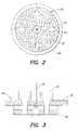
- FIG. 2represents an elevational view of the interior plate 12 , including the inlet ports 14 , burner jets 15 , a center jet port 16 (to be discussed hereinafter) and the reticulated ceramic foam 20 of the interior plate.
- the reticulated ceramic foam 20has a plurality of pores disposed therethrough.
- the inventioncontemplates the passage of fluids through the pores of the interior plate to the thermal reaction chamber 32 to reduce the deposition of particulate matter at the surface of the interior plate 12 and the walls of the thermal reaction unit 30 proximate to the interior plate 12 .
- the fluidmay include any gas that is preferably pressurized to a suitable pressure, which upon diffusion through the material is sufficient to reduce deposition on the interior plate while not detrimentally affecting the abatement treatment in the thermal reaction chamber.
- Gases contemplated herein for passage through the pores of the interior plate 12include air, CDA, oxygen-enriched air, oxygen, ozone and inert gases, e.g., Ar, N 2 , etc., and should be devoid of fuels.
- the fluidmay be introduced in a continuous or a pulsating mode, preferably a continuous mode.
- the reticulated ceramic foam interior platehelps prevent particle buildup on the interior plate in part because the exposed planar surface area is reduced thereby reducing the amount of surface available for build-up, because the reticulation of the interior plate provides smaller attachment points for growing particulate matter which will depart the interior plate upon attainment of a critical mass and because the air passing through the pores of the interior plate forms a “boundary layer,” keeping particles from migrating to the surface for deposition thereon.
- Ceramic foam bodieshave an open cell structure characterized by a plurality of interconnected voids surrounded by a web of ceramic structure. They exhibit excellent physical properties such as high strength, low thermal mass, high thermal shock resistance, and high resistance to corrosion at elevated temperatures. Preferably, the voids are uniformly distributed throughout the material and the voids are of a size that permits fluids to easily diffuse through the material. The ceramic foam bodies should not react appreciably with PFC's in the effluent to form highly volatile halogen species.
- the ceramic foam bodiesmay include alumina materials, magnesium oxide, refractory metal oxides such as ZrO 2 , silicon carbide and silicon nitride, preferably higher purity alumina materials, e.g., spinel, and yttria-doped alumina materials.
- the ceramic foam bodiesare ceramic bodies formed from yttria-doped alumina materials and yttria-stabilized zirconia-alumina (YZA). The preparation of ceramic foam bodies is well within the knowledge of those skilled in the art.
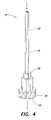
- a fluid inlet passagewaymay be incorporated into the center jet 16 of the inlet adaptor 10 (see for example FIGS. 1 , 3 and 5 for placement of the center jet in the inlet adaptor).
- An embodiment of the center jet 16is illustrated in FIG. 4 , said center jet including a pilot injection manifold tube 24 , pilot ports 26 , a pilot flame protective plate 22 and a fastening means 28 , e.g., threading complementary to threading on the inlet adaptor, whereby the center jet and the inlet adaptor may be complementarily mated with one another in a leak-tight fashion.
- the pilot flame of the center jet 16is used to ignite the burner jets 15 of the inlet adaptor.
- a bore-hole 25Through the center of the center jet 16 is a bore-hole 25 through which a stream of high velocity fluid may be introduced to inject into the thermal reaction chamber 32 (see, e.g., FIG. 5 ).
- the high velocity fluidmay include any gas sufficient to reduce deposition on the interior walls of the thermal reaction unit while not detrimentally affecting the abatement treatment in the thermal reaction chamber.
- the fluidmay be introduced in a continuous or a pulsating mode, preferably a continuous mode.
- Gases contemplated hereininclude air, CDA, oxygen-enriched air, oxygen, ozone and inert gases, e.g., Ar, N 2 , etc.
- the gasis CDA and may be oxygen-enriched.
- the high velocity fluidis heated prior to introduction into the thermal reaction chamber.
- the thermal reaction unitincludes a porous ceramic cylinder design defining the thermal reaction chamber 32 .
- High velocity airmay be directed through the pores of the thermal reaction unit 30 to at least partially reduce particle buildup on the interior walls of the thermal reaction unit.
- the ceramic cylinder of the present inventionincludes at least two ceramic rings stacked upon one another, for example as illustrated in FIG. 6C . More preferably, the ceramic cylinder includes at least about two to about twenty rings stacked upon one another. It is understood that the term “ring” is not limited to circular rings per se, but may also include rings of any polygonal or elliptical shape. Preferably, the rings are generally tubular in form.
- FIG. 6Cis a partial cut-away view of the ceramic cylinder design of the present invention showing the stacking of the individual ceramic rings 36 having a complimentary ship-lap joint design, wherein the stacked ceramic rings define the thermal reaction chamber 32 .
- the uppermost ceramic ring 40is designed to accommodate the inlet adaptor.
- the joint designis not limited to lap joints but may also include beveled joints, butt joints, lap joints and tongue and groove joints. Gasketing or sealing means, e.g., GRAFOIL® or other high temperature materials, positioned between the stacked rings is contemplated herein, especially if the stacked ceramic rings are butt jointed.
- the joints between the stacked ceramic ringsoverlap, e.g., ship-lap, to prevent infrared radiation from escaping from the thermal reaction chamber.
- Each ceramic ringmay be a circumferentially continuous ceramic ring or alternatively, may be at least two sections that may be joined together to make up the ceramic ring.
- FIG. 6Aillustrates the latter embodiment, wherein the ceramic ring 36 includes a first arcuate section 38 and a second arcuate section 40 , and when the first and second arcuate sections are coupled together, a ring is formed that defines a portion of the thermal reaction chamber 32 .
- the ceramic ringsare preferably formed of the same materials as the ceramic foam bodies discussed previously, e.g., YZA.
- the advantage of having a thermal reaction chamber defined by individual stacked ceramic ringsincludes the reduction of cracking of the ceramic rings of the chamber due to thermal shock and concomitantly a reduction of equipment costs. For example, if one ceramic ring cracks, the damaged ring may be readily replaced for a fraction of the cost and the thermal reactor placed back online immediately.
- the ceramic rings of the inventionmust be held to another to form the thermal reaction unit 30 whereby high velocity air may be directed through the pores of the ceramic rings of the thermal reaction unit to at least partially reduce particle buildup at the interior walls of the thermal reaction unit.
- a perforated metal shellmay be used to encase the stacked ceramic rings of the thermal reaction unit as well as control the flow of axially directed air through the porous interior walls of the thermal reaction unit.
- the metal shellhas the same general form of the stacked ceramic rings, e.g., a circular cylinder or a polygonal cylinder, and the metal shell includes at least two attachable sections 112 that may be joined together to make up the general form of the ceramic cylinder.
- the two attachable sections 112include ribs 114 , e.g., clampable extensions 114 , which upon coupling put pressure on the ceramic rings thereby holding the rings to one another.
- the metal shell 110has a perforated pattern whereby preferably more air is directed towards the top of the thermal reaction unit, e.g., the portion closer to the inlet adaptor 10 , than the bottom of the thermal reaction unit, e.g., the lower chamber (see FIGS. 7 and 8 ).
- the perforated patternis the same throughout the metal shell.
- “perforations”may represent any array of openings through the metal shell that do not compromise the integrity and strength of the metal shell, while ensuring that the flow of axially directed air through the porous interior walls may be controlled.
- the perforationsmay be holes having circular, polygonal or elliptical shapes or in the alternative, the perforations may be slits of various lengths and widths.
- the perforationsare holes 1/16′′ in diameter, and the perforation pattern towards the top of the thermal reaction unit has 1 hole per square inch, while the perforation pattern towards the bottom of the thermal reaction unit has 0.5 holes per square inch (in other words 2 holes per 4 square inches).
- the perforation areais about 0.1% to 1% of the area of the metal shell.
- the metal shellis constructed from corrosion-resistant metals including, but not limited to: stainless steel; austenitic nickel-chromium-iron alloys such as Inconel® 600, 601, 617, 625, 625 LCF, 706, 718, 718 SPF, X-750, MA754, 783, 792, and HX; and other nickel-based alloys such as Hastelloy B, B2, C, C22, C276, C2000, G, G2, G3 and G30.
- austenitic nickel-chromium-iron alloyssuch as Inconel® 600, 601, 617, 625, 625 LCF, 706, 718, 718 SPF, X-750, MA754, 783, 792, and HX
- other nickel-based alloyssuch as Hastelloy B, B2, C, C22, C276, C2000, G, G2, G3 and G30.
- the thermal reaction unit of the inventionis illustrated.
- the ceramic rings 36are stacked upon one another, at least one layer of a fibrous blanket 140 is wrapped around the exterior of the stacked ceramic rings and then the sections 112 of the metal shell 110 are positioned around the fibrous blanket 140 and tightly attached together by coupling the ribs 114 .
- the fibrous blanket 140can be any fibrous inorganic material having a low thermal conductivity, high temperature capability and an ability to deal with the thermal expansion coefficient mismatch of the metal shell and the ceramic rings.
- Fibrous blanket material contemplated hereinincludes, but is not limited to, spinel fibers, glass wool and other materials comprising aluminum silicates.
- the fibrous blanket 140may be a soft ceramic sleeve.
- fluid flowis axially and controllably introduced through the perforations of the metal shell, the fibrous blanket 140 and the reticulated ceramic rings of the cylinder.
- the fluidexperiences a pressure drop from the exterior of the thermal reaction unit to the interior of the thermal reaction unit in a range from about 0.05 psi to about 0.30 psi, preferably about 0.1 psi to 0.2 psi.
- the fluidmay be introduced in a continuous or a pulsating mode, preferably a continuous mode to reduce the recirculation of the fluid within the thermal reaction chamber. It should be appreciated that an increased residence time within the thermal reaction chamber, wherein the gases are recirculated, results in the formation of larger particulate material and an increased probability of deposition within the reactor.
- the fluidmay include any gas sufficient to reduce deposition on the interior walls of the ceramic rings while not detrimentally affecting the abatement treatment in the thermal reaction chamber.
- Gases contemplatedinclude air, CDA, oxygen-enriched air, oxygen, ozone and inert gases, e.g., Ar, N 2 , etc.
- the entire thermal reaction unit 30is encased within an outer stainless steel reactor shell 60 (see, e.g., FIG. 1 ), whereby an annular space 62 is created between the interior wall of the outer reactor shell 60 and the exterior wall of the thermal reaction unit 30 .
- Fluids to be introduced through the walls of the thermal reaction unitmay be introduced at ports 64 positioned on the outer reactor shell 60 .
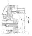
- the interior plate 12 of the inlet adaptor 10is positioned at or within the thermal reaction chamber 32 of the thermal reaction unit 30 .
- a gasket or seal 42is preferably positioned between the top ceramic ring 40 and the top plate 18 (see, e.g., FIG. 9 ).
- the gasket or seal 42may be GRAFOIL® or some other high temperature material that will prevent leakage of blow-off air through the top plate/thermal reaction unit joint, i.e., to maintain a backpressure behind the ceramic rings for gas distribution.
- FIGS. 10A and 10Bshow the buildup of particulate matter on a prior art interior plate and an interior plate according to the present invention, respectively. It can be seen that the buildup on the interior plate of the present invention (having a reticulated foam plate with fluid emanating from the pores, a reticulated ceramic cylinder with fluid emanating from the pores and high velocity fluid egression from the center jet) is substantially reduced relative to the interior plate of the prior art, which is devoid of the novel improvements disclosed herein.
- FIGS. 11A and 11Brepresent photographs of prior art thermal reaction units and the thermal reaction unit according to the present invention, respectively. It can be seen that the buildup of particulate matter on the interior walls of the thermal reaction unit of the present invention is substantially reduced relative to prior art thermal reaction unit walls. Using the apparatus and method described herein, the amount of particulate buildup at the interior walls of the thermal reaction unit is reduced by at least 50%, preferably at least 70% and more preferably at least 80%, relative to prior art units oxidizing an equivalent amount of effluent gas.
- the water quenching meansDownstream of the thermal reaction chamber is a water quenching means positioned in the lower quenching chamber 150 to capture the particulate matter that egresses from the thermal reaction chamber.
- the water quenching meansmay include a water curtain as disclosed in co-pending U.S. patent application Ser. No. 10/249,703 in the name of Glenn Tom et al., entitled “Gas Processing System Comprising a Water Curtain for Preventing Solids Deposition on Interior Walls Thereof,” which is hereby incorporated by reference in the entirety. Referring to FIG.
- the water for the water curtainis introduced at inlet 152 and water curtain 156 is formed, whereby the water curtain absorbs the heat of the combustion and decomposition reactions occurring in the thermal reaction unit 30 , eliminates build-up of particulate matter on the walls of the lower quenching chamber 150 , and absorbs water soluble gaseous products of the decomposition and combustion reactions, e.g., CO 2 , HF, etc.
- a shield 202may be positioned between the bottom-most ceramic ring 198 and the water curtain in the lower chamber 150 .
- the shieldis L-shaped and assumes the three-dimensional form of the bottom-most ceramic ring, e.g., a circular ring, so that water does not come in contact with the bottom-most ceramic ring.
- the shieldmay be constructed from any material that is water- and corrosion-resistant and thermally stable including, but not limited to: stainless steel; austenitic nickel-chromium-iron alloys such as Inconel® 600, 601, 617, 625, 625 LCF, 706, 718, 718 SPF, X-750, MA754, 783, 792, and HX; and other nickel-based alloys such as Hastelloy B, B2, C, C22, C276, C2000, G, G2, G3 and G30.
- austenitic nickel-chromium-iron alloyssuch as Inconel® 600, 601, 617, 625, 625 LCF, 706, 718, 718 SPF, X-750, MA754, 783, 792, and HX
- other nickel-based alloyssuch as Hastelloy B, B2, C, C22, C276, C2000, G, G2, G3 and G30.
- effluent gasesenter the thermal reaction chamber 32 from at least one inlet provided in the inlet adaptor 10
- the fuel/oxidant mixtureenter the thermal reaction chamber 32 from at least one burner jet 15 .
- the pilot flame of the center jet 16is used to ignite the burner jets 15 of the inlet adaptor, creating thermal reaction unit temperatures in a range from about 500° C. to about 2000° C.
- the high temperaturesfacilitate decomposition of the effluent gases that are present within the thermal reaction chamber. It is also possible that some effluent gases undergo combustion/oxidation in the presence of the fuel/oxidant mixture.
- the pressure within the thermal reaction chamberis in a range from about 0.5 atm to about 5 atm, preferably slightly subatmospheric, e.g., about 0.98 atm to about 0.99 atm.
- a water curtain 156may be used to cool the walls of the lower chamber and inhibit deposition of particulate matter on the walls. It is contemplated that some particulate matter and water soluble gases may be removed from the gas stream using the water curtain 156 . Further downstream of the water curtain, a water spraying means 154 may be positioned within the lower quenching chamber 150 to cool the gas stream, and remove the particulate matter and water soluble gases. Cooling the gas stream allows for the use of lower temperature materials downstream of the water spraying means thereby reducing material costs.
- Gases passing through the lower quenching chambermay be released to the atmosphere or alternatively may be directed to additional treatment units including, but not limited to, liquid/liquid scrubbing, physical and/or chemical adsorption, coal traps, electrostatic precipitators, and cyclones.
- additional treatment unitsincluding, but not limited to, liquid/liquid scrubbing, physical and/or chemical adsorption, coal traps, electrostatic precipitators, and cyclones.
- the concentration of the effluent gasesis preferably below detection limits, e.g., less than 1 ppm.
- the apparatus and method described hereinremoves greater than 90% of the toxic effluent components that enter the abatement apparatus, preferably greater than 98%, most preferably greater than 99.9%.
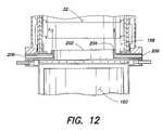
- an “air knife”is positioned within the thermal reaction unit.
- fluidmay be intermittently injected into the air knife inlet 206 , which is situated between the bottom-most ceramic ring 198 and the water quenching means in the lower quenching chamber 150 .
- the air knife inlet 206may be incorporated into the shield 202 which prevents water from wetting the bottom-most ceramic ring 198 as described hereinabove.
- the air knife fluidmay include any gas sufficient to reduce deposition on the interior walls of the thermal reaction unit while not detrimentally affecting the decomposition treatment in said unit. Gases contemplated include air, CDA, oxygen-enriched air, oxygen, ozone and inert gases, e.g., Ar, N 2 , etc.
- gasis intermittently injected through the air knife inlet 206 and exits a very thin slit 204 that is positioned parallel to the interior wall of the thermal reaction chamber 32 .
- gasesare directed upwards along the wall (in the direction of the arrows in FIG. 12 ) to force any deposited particulate matter from the surface of the interior wall.
Landscapes
- Engineering & Computer Science (AREA)
- Mechanical Engineering (AREA)
- General Engineering & Computer Science (AREA)
- Environmental & Geological Engineering (AREA)
- Chemical & Material Sciences (AREA)
- Combustion & Propulsion (AREA)
- Physical Or Chemical Processes And Apparatus (AREA)
- Incineration Of Waste (AREA)
- Devices And Processes Conducted In The Presence Of Fluids And Solid Particles (AREA)
- Treating Waste Gases (AREA)
Abstract
Description
1. Field of the Invention
The present invention relates to improved systems and methods for the abatement of industrial effluent fluids, such as effluent gases produced in semiconductor manufacturing processes, while reducing the deposition of reaction products in the treatment systems.
2. Description of the Related Art
The gaseous effluents from the manufacturing of semiconductor materials, devices, products and memory articles involve a wide variety of chemical compounds used and produced in the process facility. These compounds include inorganic and organic compounds, breakdown products of photo-resist and other reagents, and a wide variety of other gases that must be removed from the waste gas before being vented from the process facility into the atmosphere.
Semiconductor manufacturing processes utilize a variety of chemicals, many of which have extremely low human tolerance levels. Such materials include gaseous hydrides of antimony, arsenic, boron, germanium, nitrogen, phosphorous, silicon, selenium, silane, silane mixtures with phosphine, argon, hydrogen, organosilanes, halosilanes, halogens, organometallics and other organic compounds.
Halogens, e.g., fluorine (F2) and other fluorinated compounds, are particularly problematic among the various components requiring abatement. The electronics industry uses perfluorinated compounds (PFCs) in wafer processing tools to remove residue from deposition steps and to etch thin films. PFCs are recognized to be strong contributors to global warming and the electronics industry is working to reduce the emissions of these gases. The most commonly used PFCs include, but are not limited to, CF4, C2F6, SF6, C3F8, C4H8, C4H8O and NF3. In practice, these PFCs are dissociated in a plasma to generate highly reactive fluoride ions and fluorine radicals, which do the actual cleaning and/or etching. The effluent from these processing operations include mostly fluorine, silicon tetrafluoride (SiF4), hydrogen fluoride (HF), carbonyl fluoride (COF2), CF4and C2F6.
A significant problem of the semiconductor industry has been the removal of these materials from the effluent gas streams. While virtually all U.S. semiconductor manufacturing facilities utilize scrubbers or similar means for treatment of their effluent gases, the technology employed in these facilities is not capable of removing all toxic or otherwise unacceptable impurities.
One solution to this problem is to incinerate the process gas to oxidize the toxic materials, converting them to less toxic forms. Such systems are almost always over-designed in terms of treatment capacity, and typically do not have the ability to safely deal with a large number of mixed chemistry streams without posing complex reactive chemical risks. Further, conventional incinerators typically achieve less than complete combustion thereby allowing the release of pollutants, such as carbon monoxide (CO) and hydrocarbons (HC), to the atmosphere. Furthermore, one of the problems of great concern in effluent treatment is the formation of acid mist, acid vapors, acid gases and NOx (NO, NO2) prior to discharge. A further limitation of conventional incinerators is their inability to mix sufficient combustible fuel with a nonflammable process stream in order to render the resultant mixture flammable and completely combustible.
Oxygen or oxygen-enriched air may be added directly into the combustion chamber for mixing with the waste gas to increase combustion temperatures, however, oxides, particularly silicon oxides may be formed and these oxides tend to deposit on the walls of the combustion chamber. The mass of silicon oxides formed can be relatively large and the gradual deposition within the combustion chamber can induce poor combustion or cause clogging of the combustion chamber, thereby necessitating increased maintenance of the equipment. Depending on the circumstances, the cleaning operation of the abatement apparatus may need to be performed once or twice a week.
It is well known in the arts that the destruction of a halogen gas requires high temperature conditions. To handle the high temperatures, some prior art combustion chambers have included a circumferentially continuous combustion chamber made of ceramic materials to oxidize the effluent within the chamber (see, e.g., U.S. Pat. No. 6,494,711 in the name of Takemura et al., issued Dec. 17, 2002). However, under the extreme temperatures needed to abate halogen gases, these circumferentially continuous ceramic combustion chambers crack due to thermal shock and thus, the thermal insulating function of the combustion chamber fails. An alternative includes the controlled decomposition/oxidation (CDO) systems of the prior art, wherein the effluent gases undergo combustion in the metal inlet tubes, however, the metal inlet tubes of the CDO's are physically and corrosively compromised at the high temperatures, e.g., ≈1260° C.-1600° C., needed to efficiently decompose halogen compounds such as CF4.
Accordingly, it would be advantageous to provide an improved thermal reactor for the decomposition of highly thermally resistant contaminants in a waste gas that provides high temperatures, through the introduction of highly flammable gases, to ensure substantially complete decomposition of said waste stream while simultaneously reducing deposition of unwanted reaction products within the thermal reaction unit. Further, it would be advantageous to provide an improved thermal reaction chamber that does not succumb to the extreme temperatures and corrosive conditions needed to effectively abate the waste gas.
The present invention relates to methods and systems for providing controlled decomposition of gaseous liquid crystal display (LCD) and semiconductor wastes in a thermal reactor while reducing accumulation of the particulate products of said decomposition within the system. The present invention further relates to an improved thermal reactor design to reduce reactor chamber cracking during the decomposition of the gaseous waste gases.
In one aspect, the present invention relates to a thermal reactor for removing pollutant from waste gas, the thermal reactor comprising:
a) a thermal reaction unit comprising:
- i) an exterior wall having a generally tubular form and a plurality of perforations for passage of a fluid therethrough, wherein the exterior wall includes at least two sections along its length, and wherein adjacent sections are interconnected by a coupling;
- ii) a reticulated ceramic interior wall defining a thermal reaction chamber, wherein the interior wall has a generally tubular form and concentric with the exterior wall, wherein the interior wall comprises at least two ring sections in a stacked arrangement;
- iii) at least one waste gas inlet in fluid communication with the thermal reaction chamber for introducing a waste gas therein; and
- iv) at least one fuel inlet in fluid communication with the thermal reaction chamber for introducing a fuel that upon combustion produces temperature that decomposes said waste gas in the thermal reaction chamber; and
- v) means for directing a fluid through the perforations of the exterior wall and the reticulated ceramic interior wall to reduce the deposition and accumulation of particulate matter thereon; and
b) a water quench.
In yet another aspect, the present invention relates to a thermal reactor for removing pollutant from waste gas, the thermal reactor comprising:
a) a thermal reaction unit comprising:
- i) an exterior wall having a generally tubular form;
- ii) an interior wall having a generally tubular form and concentric with the exterior wall, wherein the interior wall defines a thermal reaction chamber;
- iii) a reticulated ceramic plate positioned at or within the interior wall of the thermal reaction unit, wherein the reticulated ceramic plate seals one end of the thermal reaction chamber;
- iii) at least one waste gas inlet in fluid communication with the thermal reaction chamber for introducing a waste gas therein; and
- iv) at least one fuel inlet in fluid communication with the thermal reaction chamber for introducing a fuel that upon combustion produces temperature that decomposes said waste gas within the thermal reaction unit; and
b) a water quench.
In a further aspect, the present invention relates to a method for controlled decomposition of gaseous pollutant in a waste gas in a thermal reactor, the method comprising:
- i) introducing the waste gas to a thermal reaction chamber through at least one waste gas inlet, wherein the thermal reaction chamber is defined by reticulated ceramic walls;
- ii) introducing at least one combustible fuel to the thermal reaction chamber;
- iii) igniting the combustible fuel in the thermal reaction chamber to effect formation of reaction products and heat evolution, wherein the heat evolved decomposes the waste gas;
- iv) injecting additional fluid through the reticulated ceramic walls into the thermal reaction chamber contemporaneously with the combusting of the combustible fuel, wherein the additional fluid is injected in a continuous mode at a force exceeding that of the reaction products approaching the reticulated ceramic walls of the thermal reaction chamber thereby inhibiting deposition of the reaction products thereon; and
- v) flowing the stream of reaction products into a water quench to capture the reaction products therein.
Other aspects and advantages of the invention will be more fully apparent from the ensuing disclosure and appended claims
The present invention relates to methods and systems for providing controlled decomposition of effluent gases in a thermal reactor while reducing accumulation of deposition products within the system. The present invention further relates to an improved thermal reactor design to reduce thermal reaction unit cracking during the high temperature decomposition of effluent gases.
Waste gas to be abated may include species generated by a semiconductor process and/or species that were delivered to and egressed from the semiconductor process without chemical alteration. As used herein, the term “semiconductor process” is intended to be broadly construed to include any and all processing and unit operations in the manufacture of semiconductor products and/or LCD products, as well as all operations involving treatment or processing of materials used in or produced by a semiconductor and/or LCD manufacturing facility, as well as all operations carried out in connection with the semiconductor and/or LCD manufacturing facility not involving active manufacturing (examples include conditioning of process equipment, purging of chemical delivery lines in preparation of operation, etch cleaning of process tool chambers, abatement of toxic or hazardous gases from effluents produced by the semiconductor and/or LCD manufacturing facility, etc.).
The improved thermal reaction system disclosed herein has athermal reaction unit 30 and alower quenching chamber 150 as shown inFIG. 1 . Thethermal reaction unit 30 includes athermal reaction chamber 32, and aninlet adaptor 10 including atop plate 18, at least onewaste gas inlet 14, at least onefuel inlet 17, optionally at least oneoxidant inlet 11,burner jets 15, acenter jet 16 and aninterior plate 12 which is positioned at or within the thermal reaction chamber32 (see alsoFIG. 3 for a schematic of the inlet adaptor independent of the thermal reaction unit). The inlet adaptor includes the fuel and oxidant gas inlets to provide a fuel rich gas mixture to the system for the destruction of contaminants. When oxidant is used, the fuel and oxidant may be pre-mixed prior to introduction into the thermal reaction chamber. Fuels contemplated herein include, but are not limited to, hydrogen, methane, natural gas, propane, LPG and city gas, preferably natural gas. Oxidants contemplated herein include, but are limited to, oxygen, ozone, air, clean dry air (CDA) and oxygen-enriched air. Waste gases to be abated comprise a species selected from the group consisting of CF4, C2F6, SF6, C3F8, C4H8, C4H8O, SiF4, BF3, NF3, BH3, B2H6, B5H9, NH3, PH3, SiH4, SeH2, F2, Cl2, HCl, HF, HBr, WF6, H2, Al(CH3)3, primary and secondary amines, organosilanes, organometallics, and halosilanes.
In one embodiment of the invention, the interior walls of thewaste gas inlet 14 may be altered to reduce the affinity of particles for the interior walls of the inlet. For example, a surface may be electropolished to reduce the mechanical roughness (Ra) to a value less than 30, more preferably less than 17, most preferably less than 4. Reducing the mechanical roughness reduces the amount of particulate matter that adheres to the surface as well as improving the corrosion resistance of the surface. In the alternative, the interior wall of the inlet may be coated with a fluoropolymer coating, for example Teflon® or Halar®, which will also act to reduce the amount of particulate matter adhered at the interior wall as well as allow for easy cleaning. Pure Teflon® or pure Halar® layers are preferred, however, these materials are easily scratched or abraded. As such, in practice, the fluoropolymer coating is applied as follows. First the surface to be coated is cleaned with a solvent to remove oils, etc. Then, the surface is bead-blasted to provide texture thereto. Following texturization, a pure layer of fluoropolymer, e.g., Teflon®, a layer of ceramic filled fluoropolymer, and another pure layer of fluoropolymer are deposited on the surface in that order. The resultant fluoropolymer-containing layer is essentially scratch-resistant.
In another embodiment of the invention, thewaste gas inlet 14 tube is subjected to thermophoresis, wherein the interior wall of the inlet is heated thereby reducing particle adhesion thereto. Thermophoresis may be effected by actually heating the surface of the interior wall with an on-line heater or alternatively, a hot nitrogen gas injection may be used, whereby 50-100 L per minute of hot nitrogen gas flows through the inlet. The additional advantage of the latter is the nitrogen gas flow minimizes the amount of time waste gases reside in the inlet thereby minimizing the possibility of nucleation therein.
Prior art inlet adaptors have included limited porosity ceramic plates as the interior plate of the inlet adaptor. A disadvantage of these limited porosity interior plates includes the accumulation of particles on said surface, eventually leading to inlet port clogging and flame detection error. The present invention overcomes these disadvantages by using a reticulated ceramic foam as theinterior plate 12.FIG. 2 represents an elevational view of theinterior plate 12, including theinlet ports 14,burner jets 15, a center jet port16 (to be discussed hereinafter) and the reticulatedceramic foam 20 of the interior plate. Importantly, the reticulatedceramic foam 20 has a plurality of pores disposed therethrough. As such, the invention contemplates the passage of fluids through the pores of the interior plate to thethermal reaction chamber 32 to reduce the deposition of particulate matter at the surface of theinterior plate 12 and the walls of thethermal reaction unit 30 proximate to theinterior plate 12. The fluid may include any gas that is preferably pressurized to a suitable pressure, which upon diffusion through the material is sufficient to reduce deposition on the interior plate while not detrimentally affecting the abatement treatment in the thermal reaction chamber. Gases contemplated herein for passage through the pores of theinterior plate 12 include air, CDA, oxygen-enriched air, oxygen, ozone and inert gases, e.g., Ar, N2, etc., and should be devoid of fuels. Further, the fluid may be introduced in a continuous or a pulsating mode, preferably a continuous mode.
Although not wishing to be bound by theory, the reticulated ceramic foam interior plate helps prevent particle buildup on the interior plate in part because the exposed planar surface area is reduced thereby reducing the amount of surface available for build-up, because the reticulation of the interior plate provides smaller attachment points for growing particulate matter which will depart the interior plate upon attainment of a critical mass and because the air passing through the pores of the interior plate forms a “boundary layer,” keeping particles from migrating to the surface for deposition thereon.
Ceramic foam bodies have an open cell structure characterized by a plurality of interconnected voids surrounded by a web of ceramic structure. They exhibit excellent physical properties such as high strength, low thermal mass, high thermal shock resistance, and high resistance to corrosion at elevated temperatures. Preferably, the voids are uniformly distributed throughout the material and the voids are of a size that permits fluids to easily diffuse through the material. The ceramic foam bodies should not react appreciably with PFC's in the effluent to form highly volatile halogen species. The ceramic foam bodies may include alumina materials, magnesium oxide, refractory metal oxides such as ZrO2, silicon carbide and silicon nitride, preferably higher purity alumina materials, e.g., spinel, and yttria-doped alumina materials. Most preferably, the ceramic foam bodies are ceramic bodies formed from yttria-doped alumina materials and yttria-stabilized zirconia-alumina (YZA). The preparation of ceramic foam bodies is well within the knowledge of those skilled in the art.
To further reduce particle build-up on theinterior plate 12, a fluid inlet passageway may be incorporated into thecenter jet 16 of the inlet adaptor10 (see for exampleFIGS. 1 ,3 and5 for placement of the center jet in the inlet adaptor). An embodiment of thecenter jet 16 is illustrated inFIG. 4 , said center jet including a pilot injectionmanifold tube 24,pilot ports 26, a pilot flameprotective plate 22 and a fastening means28, e.g., threading complementary to threading on the inlet adaptor, whereby the center jet and the inlet adaptor may be complementarily mated with one another in a leak-tight fashion. The pilot flame of thecenter jet 16 is used to ignite theburner jets 15 of the inlet adaptor. Through the center of thecenter jet 16 is a bore-hole 25 through which a stream of high velocity fluid may be introduced to inject into the thermal reaction chamber32 (see, e.g.,FIG. 5 ). Although not wishing to be bound by theory, it is thought that the high velocity air alters the aerodynamics and pulls gaseous and/or particulate components of the thermal reaction chamber towards the center of the chamber thereby keeping the particulate matter from getting close to the top plate and the chamber walls proximate to the top plate. The high velocity fluid may include any gas sufficient to reduce deposition on the interior walls of the thermal reaction unit while not detrimentally affecting the abatement treatment in the thermal reaction chamber. Further, the fluid may be introduced in a continuous or a pulsating mode, preferably a continuous mode. Gases contemplated herein include air, CDA, oxygen-enriched air, oxygen, ozone and inert gases, e.g., Ar, N2, etc. Preferably, the gas is CDA and may be oxygen-enriched. In another embodiment, the high velocity fluid is heated prior to introduction into the thermal reaction chamber.
In yet another embodiment, the thermal reaction unit includes a porous ceramic cylinder design defining thethermal reaction chamber 32. High velocity air may be directed through the pores of thethermal reaction unit 30 to at least partially reduce particle buildup on the interior walls of the thermal reaction unit. The ceramic cylinder of the present invention includes at least two ceramic rings stacked upon one another, for example as illustrated inFIG. 6C . More preferably, the ceramic cylinder includes at least about two to about twenty rings stacked upon one another. It is understood that the term “ring” is not limited to circular rings per se, but may also include rings of any polygonal or elliptical shape. Preferably, the rings are generally tubular in form.
Each ceramic ring may be a circumferentially continuous ceramic ring or alternatively, may be at least two sections that may be joined together to make up the ceramic ring.FIG. 6A illustrates the latter embodiment, wherein theceramic ring 36 includes a firstarcuate section 38 and a secondarcuate section 40, and when the first and second arcuate sections are coupled together, a ring is formed that defines a portion of thethermal reaction chamber 32. The ceramic rings are preferably formed of the same materials as the ceramic foam bodies discussed previously, e.g., YZA.
The advantage of having a thermal reaction chamber defined by individual stacked ceramic rings includes the reduction of cracking of the ceramic rings of the chamber due to thermal shock and concomitantly a reduction of equipment costs. For example, if one ceramic ring cracks, the damaged ring may be readily replaced for a fraction of the cost and the thermal reactor placed back online immediately.
The ceramic rings of the invention must be held to another to form thethermal reaction unit 30 whereby high velocity air may be directed through the pores of the ceramic rings of the thermal reaction unit to at least partially reduce particle buildup at the interior walls of the thermal reaction unit. Towards that end, a perforated metal shell may be used to encase the stacked ceramic rings of the thermal reaction unit as well as control the flow of axially directed air through the porous interior walls of the thermal reaction unit.FIG. 7 illustrates an embodiment of theperforated metal shell 110 of the present invention, wherein the metal shell has the same general form of the stacked ceramic rings, e.g., a circular cylinder or a polygonal cylinder, and the metal shell includes at least twoattachable sections 112 that may be joined together to make up the general form of the ceramic cylinder. The twoattachable sections 112 includeribs 114, e.g.,clampable extensions 114, which upon coupling put pressure on the ceramic rings thereby holding the rings to one another.
Themetal shell 110 has a perforated pattern whereby preferably more air is directed towards the top of the thermal reaction unit, e.g., the portion closer to theinlet adaptor 10, than the bottom of the thermal reaction unit, e.g., the lower chamber (seeFIGS. 7 and 8 ). In the alternative, the perforated pattern is the same throughout the metal shell. As defined herein, “perforations” may represent any array of openings through the metal shell that do not compromise the integrity and strength of the metal shell, while ensuring that the flow of axially directed air through the porous interior walls may be controlled. For example, the perforations may be holes having circular, polygonal or elliptical shapes or in the alternative, the perforations may be slits of various lengths and widths. In one embodiment, the perforations areholes 1/16″ in diameter, and the perforation pattern towards the top of the thermal reaction unit has 1 hole per square inch, while the perforation pattern towards the bottom of the thermal reaction unit has 0.5 holes per square inch (in other words 2 holes per 4 square inches). Preferably, the perforation area is about 0.1% to 1% of the area of the metal shell. The metal shell is constructed from corrosion-resistant metals including, but not limited to: stainless steel; austenitic nickel-chromium-iron alloys such as Inconel® 600, 601, 617, 625, 625 LCF, 706, 718, 718 SPF, X-750, MA754, 783, 792, and HX; and other nickel-based alloys such as Hastelloy B, B2, C, C22, C276, C2000, G, G2, G3 and G30.
Referring toFIG. 8 , the thermal reaction unit of the invention is illustrated. The ceramic rings36 are stacked upon one another, at least one layer of afibrous blanket 140 is wrapped around the exterior of the stacked ceramic rings and then thesections 112 of themetal shell 110 are positioned around thefibrous blanket 140 and tightly attached together by coupling theribs 114. Thefibrous blanket 140 can be any fibrous inorganic material having a low thermal conductivity, high temperature capability and an ability to deal with the thermal expansion coefficient mismatch of the metal shell and the ceramic rings. Fibrous blanket material contemplated herein includes, but is not limited to, spinel fibers, glass wool and other materials comprising aluminum silicates. In the alternative, thefibrous blanket 140 may be a soft ceramic sleeve.
In practice, fluid flow is axially and controllably introduced through the perforations of the metal shell, thefibrous blanket 140 and the reticulated ceramic rings of the cylinder. The fluid experiences a pressure drop from the exterior of the thermal reaction unit to the interior of the thermal reaction unit in a range from about 0.05 psi to about 0.30 psi, preferably about 0.1 psi to 0.2 psi. The fluid may be introduced in a continuous or a pulsating mode, preferably a continuous mode to reduce the recirculation of the fluid within the thermal reaction chamber. It should be appreciated that an increased residence time within the thermal reaction chamber, wherein the gases are recirculated, results in the formation of larger particulate material and an increased probability of deposition within the reactor. The fluid may include any gas sufficient to reduce deposition on the interior walls of the ceramic rings while not detrimentally affecting the abatement treatment in the thermal reaction chamber. Gases contemplated include air, CDA, oxygen-enriched air, oxygen, ozone and inert gases, e.g., Ar, N2, etc.
To introduce fluid to the walls of the thermal reaction unit for passage through to thethermal reaction chamber 32, the entirethermal reaction unit 30 is encased within an outer stainless steel reactor shell60 (see, e.g.,FIG. 1 ), whereby anannular space 62 is created between the interior wall of theouter reactor shell 60 and the exterior wall of thethermal reaction unit 30. Fluids to be introduced through the walls of the thermal reaction unit may be introduced atports 64 positioned on theouter reactor shell 60.
Referring toFIG. 1 , theinterior plate 12 of theinlet adaptor 10 is positioned at or within thethermal reaction chamber 32 of thethermal reaction unit 30. To ensure that gases within the thermal reaction unit do not leak from the region where the inlet adaptor contacts the thermal reaction unit, a gasket or seal42 is preferably positioned between the topceramic ring 40 and the top plate18 (see, e.g.,FIG. 9 ). The gasket or seal42 may be GRAFOIL® or some other high temperature material that will prevent leakage of blow-off air through the top plate/thermal reaction unit joint, i.e., to maintain a backpressure behind the ceramic rings for gas distribution.
Downstream of the thermal reaction chamber is a water quenching means positioned in thelower quenching chamber 150 to capture the particulate matter that egresses from the thermal reaction chamber. The water quenching means may include a water curtain as disclosed in co-pending U.S. patent application Ser. No. 10/249,703 in the name of Glenn Tom et al., entitled “Gas Processing System Comprising a Water Curtain for Preventing Solids Deposition on Interior Walls Thereof,” which is hereby incorporated by reference in the entirety. Referring toFIG. 1 , the water for the water curtain is introduced atinlet 152 andwater curtain 156 is formed, whereby the water curtain absorbs the heat of the combustion and decomposition reactions occurring in thethermal reaction unit 30, eliminates build-up of particulate matter on the walls of thelower quenching chamber 150, and absorbs water soluble gaseous products of the decomposition and combustion reactions, e.g., CO2, HF, etc.
To ensure that the bottom-most ceramic ring does not get wet, a shield202 (see, e.g.,FIG. 12 ) may be positioned between the bottom-mostceramic ring 198 and the water curtain in thelower chamber 150. Preferably, the shield is L-shaped and assumes the three-dimensional form of the bottom-most ceramic ring, e.g., a circular ring, so that water does not come in contact with the bottom-most ceramic ring. The shield may be constructed from any material that is water- and corrosion-resistant and thermally stable including, but not limited to: stainless steel; austenitic nickel-chromium-iron alloys such as Inconel® 600, 601, 617, 625, 625 LCF, 706, 718, 718 SPF, X-750, MA754, 783, 792, and HX; and other nickel-based alloys such as Hastelloy B, B2, C, C22, C276, C2000, G, G2, G3 and G30.
In practice, effluent gases enter thethermal reaction chamber 32 from at least one inlet provided in theinlet adaptor 10, and the fuel/oxidant mixture enter thethermal reaction chamber 32 from at least oneburner jet 15. The pilot flame of thecenter jet 16 is used to ignite theburner jets 15 of the inlet adaptor, creating thermal reaction unit temperatures in a range from about 500° C. to about 2000° C. The high temperatures facilitate decomposition of the effluent gases that are present within the thermal reaction chamber. It is also possible that some effluent gases undergo combustion/oxidation in the presence of the fuel/oxidant mixture. The pressure within the thermal reaction chamber is in a range from about 0.5 atm to about 5 atm, preferably slightly subatmospheric, e.g., about 0.98 atm to about 0.99 atm.
Following decomposition/combustion, the effluent gases pass to thelower chamber 150 wherein awater curtain 156 may be used to cool the walls of the lower chamber and inhibit deposition of particulate matter on the walls. It is contemplated that some particulate matter and water soluble gases may be removed from the gas stream using thewater curtain 156. Further downstream of the water curtain, a water spraying means154 may be positioned within thelower quenching chamber 150 to cool the gas stream, and remove the particulate matter and water soluble gases. Cooling the gas stream allows for the use of lower temperature materials downstream of the water spraying means thereby reducing material costs. Gases passing through the lower quenching chamber may be released to the atmosphere or alternatively may be directed to additional treatment units including, but not limited to, liquid/liquid scrubbing, physical and/or chemical adsorption, coal traps, electrostatic precipitators, and cyclones. Following passage through the thermal reaction unit and the lower quenching chamber, the concentration of the effluent gases is preferably below detection limits, e.g., less than 1 ppm. Specifically, the apparatus and method described herein removes greater than 90% of the toxic effluent components that enter the abatement apparatus, preferably greater than 98%, most preferably greater than 99.9%.
In an alternative embodiment, an “air knife” is positioned within the thermal reaction unit. Referring toFIG. 12 , fluid may be intermittently injected into theair knife inlet 206, which is situated between the bottom-mostceramic ring 198 and the water quenching means in thelower quenching chamber 150. Theair knife inlet 206 may be incorporated into theshield 202 which prevents water from wetting the bottom-mostceramic ring 198 as described hereinabove. The air knife fluid may include any gas sufficient to reduce deposition on the interior walls of the thermal reaction unit while not detrimentally affecting the decomposition treatment in said unit. Gases contemplated include air, CDA, oxygen-enriched air, oxygen, ozone and inert gases, e.g., Ar, N2, etc. In operation, gas is intermittently injected through theair knife inlet 206 and exits a verythin slit 204 that is positioned parallel to the interior wall of thethermal reaction chamber 32. Thus, gases are directed upwards along the wall (in the direction of the arrows inFIG. 12 ) to force any deposited particulate matter from the surface of the interior wall.
To demonstrate the abatement effectiveness of the improved thermal reactor described herein, a series of experiments were performed to quantify the efficiency of abatement using said thermal reactor. It can be seen that greater than 99% of the test gases were abated using the improved thermal reactor, as shown in Table 1.
| TABLE 1 |
| Results of abatement experiments using |
| the embodiments described herein. |
| Test gas | Flow rate/slm | Fuel/slm | DRE, % | ||
| C2F6 | 2.00 | 50 | >99.9% | ||
| C3F8 | 2.00 | 45 | >99.9% | ||
| NF3 | 2.00 | 33 | >99.9% | ||
| SF6 | 5.00 | 40 | 99.6% | ||
| CF4 | 0.25 | 86 | 99.5% | ||
| CF4 | 0.25 | 83 | 99.5% | ||
Although the invention has been variously described herein with reference to illustrative embodiments and features, it will be appreciated that the embodiments and features described hereinabove are not intended to limit the invention, and that other variations, modifications and other embodiments will readily suggest themselves to those of ordinary skill in the art, based on the disclosure herein. The invention therefore is to be broadly construed, consistent with the claims hereafter set forth.
Claims (25)
1. A thermal abatement reactor for removing pollutant from waste gas, the thermal reactor comprising:
a thermal reaction unit comprising:
an exterior wall having a plurality of perforations for passage of a fluid therethrough;
a porous ceramic interior wall defining a thermal reaction chamber, wherein the interior wall comprises at least two ring sections in a stacked arrangement;
at least one waste gas inlet in fluid communication with the thermal reaction chamber for introducing a waste gas therein; and
at least one fuel inlet in fluid communication with the thermal reaction chamber for introducing a fuel for use during decomposition of said waste gas in the thermal reaction chamber; and
means for directing a fluid through the one or more perforations of the exterior wall and the porous ceramic interior wall to reduce the deposition and accumulation of particulate matter thereon; and
a water quench unit coupled to the thermal reaction unit and adapted to receive a gas stream from the thermal reaction unit;
wherein the total number of perforations in proximity to the waste gas inlet and the fuel inlet is greater than the total number of perforations in proximity to the water quench unit.
2. The thermal abatement reactor ofclaim 1 , coupled in waste gas receiving relationship to a process facility selected from the group consisting of a semiconductor manufacturing process facility and a liquid crystal display (LCD) process facility.
3. The thermal abatement reactor ofclaim 1 , wherein the metal exterior wall has perforations that provide a pressure drop across the thermal reaction unit of greater than about 0.1 psi.
4. The thermal abatement reactor ofclaim 1 , wherein the thermal reaction unit is adapted so that more fluid flows through the porous ceramic interior wall in proximity to the waste gas inlet and the fuel inlet than in proximity to the water quench unit.
5. The thermal abatement reactor ofclaim 1 , wherein the at least two ring sections are complimentarily jointed for connection of adjacent stacked rings.
6. The thermal abatement reactor ofclaim 1 , wherein the thermal reaction unit further comprises a porous ceramic plate positioned at or within the interior wall of the thermal reaction chamber, and wherein the porous ceramic plate encloses one end of said thermal reaction chamber.
7. The thermal abatement reactor ofclaim 6 , further comprising means for directing fluid through the porous ceramic plate to reduce deposition and accumulation of particulate matter thereon.
8. The thermal abatement reactor ofclaim 6 , further comprising a center jet in fluid communication with the thermal reaction chamber, wherein the center jet is in proximity to the at least one waste gas inlet and the at least one fuel inlet, and wherein the center jet is adapted to introduce high velocity fluid into the thermal reaction chamber through the center jet during decomposition of the waste gas to inhibit deposition and accumulation of particulate matter on the interior wall and porous ceramic plate of the thermal reaction chamber proximate to the center jet.
9. The thermal abatement reactor ofclaim 1 , further comprising a water resistant shield between the thermal reaction unit and the water quench unit.
10. The thermal abatement reactor ofclaim 1 , further comprising an outer reactor shell having an outer reactor shell interior wall, wherein an annular space is formed between the outer reactor shell interior wall and the exterior wall of the thermal reaction unit.
11. The thermal abatement reactor ofclaim 1 , wherein the at least one waste gas inlet has an interior wall, and wherein the interior wall is coated with at least one layer of a coating material comprising a fluoropolymer.
12. The thermal abatement reactor ofclaim 1 , wherein the porous ceramic interior wall comprises a reticulated ceramic interior wall.
13. A thermal abatement reactor for removing pollutant from waste gas, the thermal reactor comprising:
a thermal reaction unit comprising:
an exterior wall having a plurality of perforations for passage of a fluid therethrough;
a porous ceramic interior wall defining a thermal reaction chamber, wherein the interior wall comprises at least two ring sections in a stacked arrangement;
at least one waste gas inlet in fluid communication with the thermal reaction chamber for introducing a waste gas therein; and
at least one fuel inlet in fluid communication with the thermal reaction chamber for introducing a fuel for use during decomposition of said waste gas in the thermal reaction chamber; and
means for directing a fluid through the one or more perforations of the exterior wall and the porous ceramic interior wall to reduce the deposition and accumulation of particulate matter thereon;
a water quench unit coupled to the thermal reaction unit and adapted to receive a gas stream from the thermal reaction unit; and
a fibrous material disposed between the exterior wall and the porous ceramic interior wall.
14. The thermal abatement reactor of13, wherein the fibrous material comprises material selected from the group consisting of spinel fibers, glass wool and aluminum silicate.
15. The thermal abatement reactor ofclaim 13 , coupled in waste gas receiving relationship to a process facility selected from the group consisting of a semiconductor manufacturing process facility and a liquid crystal display (LCD) process facility.
16. The thermal abatement reactor ofclaim 13 , wherein the metal exterior wall has perforations that provide a pressure drop across the thermal reaction unit of greater than about 0.1 psi.
17. The thermal reactor ofclaim 13 , wherein the thermal reaction unit is adapted so that more fluid flows through the porous ceramic interior wall in proximity to the waste gas inlet and the fuel inlet than in proximity to the water quench unit.
18. The thermal abatement reactor ofclaim 13 , wherein the at least two ring sections are complimentarily jointed for connection of adjacent stacked rings.
19. The thermal abatement reactor ofclaim 13 , wherein the thermal reaction unit further comprises a porous ceramic plate positioned at or within the interior wall of the thermal reaction chamber, and wherein the porous ceramic plate encloses one end of said thermal reaction chamber.
20. The thermal abatement reactor ofclaim 19 , further comprising means for directing fluid through the porous ceramic plate to reduce deposition and accumulation of particulate matter thereon.
21. The thermal reactor ofclaim 19 , further comprising a center jet in fluid communication with the thermal reaction chamber, wherein the center jet is in proximity to the at least one waste gas inlet and the at least one fuel inlet, and wherein the center jet is adapted to introduce high velocity fluid into the thermal reaction chamber through the center jet during decomposition of the waste gas to inhibit deposition and accumulation of particulate matter on the interior wall and porous ceramic plate of the thermal reaction chamber proximate to the center jet.
22. The thermal abatement reactor ofclaim 13 , further comprising a water resistant shield between the thermal reaction unit and the water quench unit.
23. The thermal abatement reactor ofclaim 13 , further comprising an outer reactor shell having an outer reactor shell interior wall, wherein an annular space is formed between the outer reactor shell interior wall and the exterior wall of the thermal reaction unit.
24. The thermal abatement reactor ofclaim 13 , wherein the at least one waste gas inlet has an interior wall, and wherein the interior wall is coated with at least one layer of a coating material comprising a fluoropolymer.
25. The thermal abatement reactor ofclaim 13 , wherein the porous ceramic interior wall comprises a reticulated ceramic interior wall.
Priority Applications (10)
| Application Number | Priority Date | Filing Date | Title |
|---|---|---|---|
| US10/987,921US7736599B2 (en) | 2004-11-12 | 2004-11-12 | Reactor design to reduce particle deposition during process abatement |
| TW098138160ATW201023244A (en) | 2004-11-12 | 2005-11-11 | Reactor design to reduce particle deposition during process abatement |
| TW094139700ATWI323003B (en) | 2004-11-12 | 2005-11-11 | Reactor design to reduce particle deposition during process abatement |
| JP2007541359AJP2008519959A (en) | 2004-11-12 | 2005-11-12 | Reactor structure to reduce particle build-up during reduction processing |
| CN2005800393936ACN101069041B (en) | 2004-11-12 | 2005-11-12 | Reactor Design to Reduce Particle Deposition During Process Contaminant Abatement |
| EP05820049AEP1828680B1 (en) | 2004-11-12 | 2005-11-12 | Reactor design to reduce particle deposition during effluent abatement process |
| PCT/US2005/040960WO2006053231A2 (en) | 2004-11-12 | 2005-11-12 | Reactor design to reduce particle deposition during process abatement |
| KR1020077013112AKR20070086017A (en) | 2004-11-12 | 2005-11-12 | Reaction apparatus to reduce particle deposition during process abatement |
| IL183122AIL183122A0 (en) | 2004-11-12 | 2007-05-10 | Reactor design to reduce particle deposition during process abatement |
| US11/838,435US7985379B2 (en) | 2004-11-12 | 2007-08-14 | Reactor design to reduce particle deposition during process abatement |
Applications Claiming Priority (1)
| Application Number | Priority Date | Filing Date | Title |
|---|---|---|---|
| US10/987,921US7736599B2 (en) | 2004-11-12 | 2004-11-12 | Reactor design to reduce particle deposition during process abatement |
Related Child Applications (1)
| Application Number | Title | Priority Date | Filing Date |
|---|---|---|---|
| US11/838,435ContinuationUS7985379B2 (en) | 2004-11-12 | 2007-08-14 | Reactor design to reduce particle deposition during process abatement |
Publications (2)
| Publication Number | Publication Date |
|---|---|
| US20060104879A1 US20060104879A1 (en) | 2006-05-18 |
| US7736599B2true US7736599B2 (en) | 2010-06-15 |
Family
ID=36115480
Family Applications (2)
| Application Number | Title | Priority Date | Filing Date |
|---|---|---|---|
| US10/987,921Expired - Fee RelatedUS7736599B2 (en) | 2004-11-12 | 2004-11-12 | Reactor design to reduce particle deposition during process abatement |
| US11/838,435Expired - Fee RelatedUS7985379B2 (en) | 2004-11-12 | 2007-08-14 | Reactor design to reduce particle deposition during process abatement |
Family Applications After (1)
| Application Number | Title | Priority Date | Filing Date |
|---|---|---|---|
| US11/838,435Expired - Fee RelatedUS7985379B2 (en) | 2004-11-12 | 2007-08-14 | Reactor design to reduce particle deposition during process abatement |
Country Status (8)
| Country | Link |
|---|---|
| US (2) | US7736599B2 (en) |
| EP (1) | EP1828680B1 (en) |
| JP (1) | JP2008519959A (en) |
| KR (1) | KR20070086017A (en) |
| CN (1) | CN101069041B (en) |
| IL (1) | IL183122A0 (en) |
| TW (2) | TW201023244A (en) |
| WO (1) | WO2006053231A2 (en) |
Cited By (7)
| Publication number | Priority date | Publication date | Assignee | Title |
|---|---|---|---|---|
| US20090098492A1 (en)* | 2004-11-18 | 2009-04-16 | Applied Materials, Inc. | Methods and apparatus for starting and operating a thermal abatement system |
| US9919939B2 (en) | 2011-12-06 | 2018-03-20 | Delta Faucet Company | Ozone distribution in a faucet |
| US10690341B2 (en) | 2017-01-06 | 2020-06-23 | Alzeta Corporation | Systems and methods for improved waste gas abatement |
| US10859264B2 (en) | 2017-03-07 | 2020-12-08 | 8 Rivers Capital, Llc | System and method for combustion of non-gaseous fuels and derivatives thereof |
| US11199327B2 (en) | 2017-03-07 | 2021-12-14 | 8 Rivers Capital, Llc | Systems and methods for operation of a flexible fuel combustor |
| US11458214B2 (en) | 2015-12-21 | 2022-10-04 | Delta Faucet Company | Fluid delivery system including a disinfectant device |
| US11572828B2 (en) | 2018-07-23 | 2023-02-07 | 8 Rivers Capital, Llc | Systems and methods for power generation with flameless combustion |
Families Citing this family (74)
| Publication number | Priority date | Publication date | Assignee | Title |
|---|---|---|---|---|
| US7569193B2 (en)* | 2003-12-19 | 2009-08-04 | Applied Materials, Inc. | Apparatus and method for controlled combustion of gaseous pollutants |
| US7316721B1 (en)* | 2004-02-09 | 2008-01-08 | Porvair, Plc | Ceramic foam insulator with thermal expansion joint |
| US7736599B2 (en)* | 2004-11-12 | 2010-06-15 | Applied Materials, Inc. | Reactor design to reduce particle deposition during process abatement |
| US7682574B2 (en)* | 2004-11-18 | 2010-03-23 | Applied Materials, Inc. | Safety, monitoring and control features for thermal abatement reactor |
| GB0509163D0 (en)* | 2005-05-05 | 2005-06-15 | Boc Group Plc | Gas combustion apparatus |
| US8617672B2 (en) | 2005-07-13 | 2013-12-31 | Applied Materials, Inc. | Localized surface annealing of components for substrate processing chambers |
| KR101036734B1 (en)* | 2005-10-31 | 2011-05-24 | 어플라이드 머티어리얼스, 인코포레이티드 | Process reduction reactor |
| WO2007109082A2 (en) | 2006-03-16 | 2007-09-27 | Applied Materials, Inc. | Methods and apparatus for improving operation of an electronic device manufacturing system |
| US7522974B2 (en)* | 2006-08-23 | 2009-04-21 | Applied Materials, Inc. | Interface for operating and monitoring abatement systems |
| KR20090063219A (en)* | 2006-08-23 | 2009-06-17 | 어플라이드 머티어리얼스, 인코포레이티드 | Methods and systems for monitoring and operating mitigation systems |
| US20080092806A1 (en)* | 2006-10-19 | 2008-04-24 | Applied Materials, Inc. | Removing residues from substrate processing components |
| US8591819B2 (en)* | 2006-12-05 | 2013-11-26 | Ebara Corporation | Combustion-type exhaust gas treatment apparatus |
| US7981262B2 (en) | 2007-01-29 | 2011-07-19 | Applied Materials, Inc. | Process kit for substrate processing chamber |
| CN101678407A (en)* | 2007-05-25 | 2010-03-24 | 应用材料股份有限公司 | Method and apparatus for efficient operation of an abatement system |
| US7942969B2 (en) | 2007-05-30 | 2011-05-17 | Applied Materials, Inc. | Substrate cleaning chamber and components |
| WO2008156687A1 (en)* | 2007-06-15 | 2008-12-24 | Applied Materials, Inc. | Methods and systems for designing and validating operation of abatement systems |
| DE102007042543A1 (en)* | 2007-09-07 | 2009-03-12 | Choren Industries Gmbh | Process and apparatus for treating laden hot gas |
| WO2009055750A1 (en)* | 2007-10-26 | 2009-04-30 | Applied Materials, Inc. | Methods and apparatus for smart abatement using an improved fuel circuit |
| US20090149996A1 (en)* | 2007-12-05 | 2009-06-11 | Applied Materials, Inc. | Multiple inlet abatement system |
| KR100901267B1 (en)* | 2008-01-25 | 2009-06-09 | 고등기술연구원연구조합 | Oxygen Enriched Syngas Combustor |
| KR101581673B1 (en)* | 2008-02-05 | 2015-12-31 | 어플라이드 머티어리얼스, 인코포레이티드 | Systems and methods for treating flammable effluent gases from manufacturing processes |
| US20090222128A1 (en)* | 2008-02-05 | 2009-09-03 | Applied Materials, Inc. | Methods and apparatus for operating an electronic device manufacturing system |
| EP2090825A1 (en)* | 2008-02-14 | 2009-08-19 | Siemens Aktiengesellschaft | Burner element and burner with corrosion-resistant insert |
| US20100119984A1 (en)* | 2008-11-10 | 2010-05-13 | Fox Allen G | Abatement system |
| US10018115B2 (en) | 2009-02-26 | 2018-07-10 | 8 Rivers Capital, Llc | System and method for high efficiency power generation using a carbon dioxide circulating working fluid |
| US9068743B2 (en)* | 2009-02-26 | 2015-06-30 | 8 Rivers Capital, LLC & Palmer Labs, LLC | Apparatus for combusting a fuel at high pressure and high temperature, and associated system |
| US8596075B2 (en) | 2009-02-26 | 2013-12-03 | Palmer Labs, Llc | System and method for high efficiency power generation using a carbon dioxide circulating working fluid |
| ES2733083T3 (en) | 2009-02-26 | 2019-11-27 | 8 Rivers Capital Llc | Apparatus and method for burning a fuel at high pressure and high temperature, and associated system and device |
| US8986002B2 (en)* | 2009-02-26 | 2015-03-24 | 8 Rivers Capital, Llc | Apparatus for combusting a fuel at high pressure and high temperature, and associated system |
| US20130064730A1 (en)* | 2010-06-21 | 2013-03-14 | Izumi Nakayama | Gas abatement system |
| KR101253698B1 (en)* | 2010-08-06 | 2013-04-11 | 주식회사 글로벌스탠다드테크놀로지 | Burning apparatus for purifying noxious gas |
| US8869889B2 (en) | 2010-09-21 | 2014-10-28 | Palmer Labs, Llc | Method of using carbon dioxide in recovery of formation deposits |
| CA2854402C (en) | 2011-11-02 | 2020-03-24 | 8 Rivers Capital, Llc | Power generating system and corresponding method |
| BR112014011696B1 (en)* | 2011-11-15 | 2018-10-09 | Outotec Oyj | process for manufacture of ferrochrome alloy |
| CN104302743B (en) | 2012-02-11 | 2016-11-09 | 帕尔默实验室有限责任公司 | Partial Oxidation Reactions with Closed Cycle Quenching |
| TWD155845S (en)* | 2012-03-16 | 2013-09-01 | 荏原製作所股份有限公司 | Scraper for exhaust gas treatment device |
| US9089811B2 (en)* | 2012-04-30 | 2015-07-28 | Highvac Corp. | Coaxial / coaxial treatment module |
| GB2504335A (en)* | 2012-07-26 | 2014-01-29 | Edwards Ltd | Radiant burner for the combustion of manufacturing effluent gases. |
| CN103308662B (en)* | 2013-06-07 | 2015-07-08 | 北京理工大学 | A high temperature and high pressure single droplet evaporation and combustion device |
| GB2516267B (en)* | 2013-07-17 | 2016-08-17 | Edwards Ltd | Head assembly |
| JP6250332B2 (en) | 2013-08-27 | 2017-12-20 | 8 リバーズ キャピタル,エルエルシー | Gas turbine equipment |
| CN103529078B (en)* | 2013-10-25 | 2016-04-13 | 中国人民解放军装备学院 | Drop evaporation ignition experiment device and using method thereof under a kind of high temperature and high pressure environment |
| CN105090999B (en)* | 2014-05-12 | 2018-11-20 | 日本派欧尼株式会社 | The combustion-type purification device of exhaust gas |
| JP6258797B2 (en)* | 2014-06-27 | 2018-01-10 | 日本パイオニクス株式会社 | Exhaust gas combustion purification system |
| TWI691644B (en) | 2014-07-08 | 2020-04-21 | 美商八河資本有限公司 | Method and system for power production with improved efficiency |
| GB2528444B (en)* | 2014-07-21 | 2018-06-20 | Edwards Ltd | Abatement apparatus |
| GB2528445B (en) | 2014-07-21 | 2018-06-20 | Edwards Ltd | Separator apparatus |
| US11231224B2 (en) | 2014-09-09 | 2022-01-25 | 8 Rivers Capital, Llc | Production of low pressure liquid carbon dioxide from a power production system and method |
| MY176626A (en) | 2014-09-09 | 2020-08-19 | 8 Rivers Capital Llc | Production of low pressure liquid carbon dioxide from a power production system and method |
| US10961920B2 (en) | 2018-10-02 | 2021-03-30 | 8 Rivers Capital, Llc | Control systems and methods suitable for use with power production systems and methods |
| US11686258B2 (en) | 2014-11-12 | 2023-06-27 | 8 Rivers Capital, Llc | Control systems and methods suitable for use with power production systems and methods |
| MA40950A (en) | 2014-11-12 | 2017-09-19 | 8 Rivers Capital Llc | SUITABLE CONTROL SYSTEMS AND PROCEDURES FOR USE WITH POWER GENERATION SYSTEMS AND PROCESSES |
| KR102602774B1 (en) | 2015-06-15 | 2023-11-15 | 8 리버스 캐피탈, 엘엘씨 | System and method for starting up a power production plant |
| CN106298421A (en)* | 2015-06-23 | 2017-01-04 | 应用材料公司 | In order to the method and apparatus eliminating the spontaneous combustion by-product from ion implantation technology |
| GB201515489D0 (en)* | 2015-09-01 | 2015-10-14 | Edwards Ltd | Abatement apparatus |
| CA3015050C (en) | 2016-02-18 | 2024-01-02 | 8 Rivers Capital, Llc | System and method for power production including methanation |
| MY190077A (en) | 2016-02-26 | 2022-03-24 | 8 Rivers Capital Llc | Systems and methods for controlling a power plant |
| GB2550382B (en)* | 2016-05-18 | 2020-04-22 | Edwards Ltd | Burner Inlet Assembly |
| EA039851B1 (en) | 2016-09-13 | 2022-03-21 | 8 Риверз Кэпитл, Ллк | System and method for power production using partial oxidation |
| CN111315971B (en) | 2017-07-07 | 2021-12-10 | 鉴锋国际股份有限公司 | Device for controlling decomposition and oxidation of gas pollutants |
| BR112020003886A2 (en) | 2017-08-28 | 2020-09-01 | 8 Rivers Capital, Llc | low-grade heat optimization of recoverable supercritical co2 energy cycles |
| EP3759322B9 (en) | 2018-03-02 | 2024-02-14 | 8 Rivers Capital, LLC | Systems and methods for power production using a carbon dioxide working fluid |
| GB2579197B (en)* | 2018-11-22 | 2021-06-09 | Edwards Ltd | Abatement method |
| GB2584675B (en)* | 2019-06-10 | 2021-11-17 | Edwards Ltd | Inlet assembly for an abatement apparatus |
| EP4520935A3 (en) | 2019-10-22 | 2025-05-21 | 8 Rivers Capital, LLC | Control schemes for thermal management of power production systems and methods |
| CN111412481B (en)* | 2020-03-19 | 2023-01-10 | 长江存储科技有限责任公司 | Exhaust gas treatment device |
| WO2021212146A1 (en)* | 2020-04-16 | 2021-10-21 | Integrated Global Services Inc. | System, method, and apparatus for ameliorating deposits in selective catalytic reduction systems for the reduction of nitrogen oxide emissions in steam methane reformers |
| KR102427056B1 (en)* | 2020-06-02 | 2022-08-01 | 씨에스케이(주) | Burner for Scrubber |
| CN114673998A (en)* | 2020-12-25 | 2022-06-28 | 上海协微环境科技有限公司 | Exhaust gas treatment device |
| CN114688547A (en)* | 2020-12-25 | 2022-07-01 | 上海协微环境科技有限公司 | Exhaust gas treatment device |
| CN112915718B (en)* | 2021-01-25 | 2022-05-17 | 北京京仪自动化装备技术股份有限公司 | Semiconductor processing waste gas treatment equipment |
| CN113058356B (en)* | 2021-03-17 | 2022-06-21 | 北京京仪自动化装备技术股份有限公司 | Waste gas treatment device for semiconductor DPY (differential pressure Y) process |
| CN113058360B (en)* | 2021-03-17 | 2022-06-21 | 北京京仪自动化装备技术股份有限公司 | Online detachable waste gas treatment device |
| GB2608821A (en)* | 2021-07-13 | 2023-01-18 | Edwards Ltd | Inlet assembly |
Citations (232)
| Publication number | Priority date | Publication date | Assignee | Title |
|---|---|---|---|---|
| US2819151A (en) | 1954-03-02 | 1958-01-07 | Flemmert Gosta Lennart | Process for burning silicon fluorides to form silica |
| US3185846A (en) | 1961-05-16 | 1965-05-25 | Bailey Meter Co | Ultra-violet radiation flame monitor |
| US3203759A (en) | 1960-11-03 | 1965-08-31 | Flemmert Gosta Lennart | Method of preparing silicon dioxide |
| US3276506A (en) | 1963-12-19 | 1966-10-04 | Apparatcbau Eugen Schrag Komma | Burner control device |
| FR2062565A5 (en) | 1969-09-26 | 1971-06-25 | Electronics Corp America | |
| US3603711A (en) | 1969-09-17 | 1971-09-07 | Edgar S Downs | Combination pressure atomizer and surface-type burner for liquid fuel |
| US3698696A (en) | 1971-06-14 | 1972-10-17 | Standard Int Corp | Combustion mixture control system for calenders |
| US3813852A (en) | 1972-03-22 | 1974-06-04 | Elkem Spigerverket As | Method of recovering fluorine from waste gases |
| US3845191A (en) | 1972-06-02 | 1974-10-29 | Du Pont | Method of removing halocarbons from gases |
| US3898040A (en) | 1972-06-29 | 1975-08-05 | Universal Oil Prod Co | Recuperative form of thermal-catalytic incinerator |
| US3949057A (en) | 1973-01-29 | 1976-04-06 | Croll-Reynolds Company, Inc. | Air pollution control of oxides of nitrogen |
| US3969485A (en) | 1971-10-28 | 1976-07-13 | Flemmert Goesta Lennart | Process for converting silicon-and-fluorine-containing waste gases into silicon dioxide and hydrogen fluoride |
| US3969482A (en) | 1974-04-25 | 1976-07-13 | Teller Environmental Systems, Inc. | Abatement of high concentrations of acid gas emissions |
| US3983021A (en) | 1971-06-09 | 1976-09-28 | Monsanto Company | Nitrogen oxide decomposition process |
| US4011298A (en) | 1973-12-18 | 1977-03-08 | Chiyoda Chemical Engineering & Construction Co. Ltd. | Method for simultaneous removal of SOx and NOx |
| US4059386A (en) | 1976-01-21 | 1977-11-22 | A. O. Smith Corporation | Combustion heating apparatus to improve operation of gas pilot burners |
| US4083607A (en) | 1976-05-05 | 1978-04-11 | Mott Lambert H | Gas transport system for powders |
| US4154141A (en) | 1977-05-17 | 1979-05-15 | The United States Of America As Represented By The Secretary Of The Army | Ultrafast, linearly-deflagration ignition system |
| US4172708A (en) | 1977-04-22 | 1979-10-30 | Shell Internationale Research Maatschappij B.V. | Process and apparatus for use with a reactor for the partial combustion of finely divided solid fuel |
| GB2028998A (en) | 1978-08-25 | 1980-03-12 | Satronic Ag | Improvements in or relating to flame monitors |
| US4206189A (en) | 1977-01-04 | 1980-06-03 | Belov Viktor Y | Method of producing hydrogen fluoride and silicon dioxide from silicon tetra-fluoride |
| US4236464A (en) | 1978-03-06 | 1980-12-02 | Aerojet-General Corporation | Incineration of noxious materials |
| US4238460A (en) | 1979-02-02 | 1980-12-09 | United States Steel Corporation | Waste gas purification systems and methods |
| US4243372A (en) | 1979-02-05 | 1981-01-06 | Electronics Corporation Of America | Burner control system |
| US4296079A (en) | 1978-02-10 | 1981-10-20 | Vinings Chemical Company | Method of manufacturing aluminum sulfate from flue gas |
| US4374649A (en) | 1981-02-12 | 1983-02-22 | Burns & Roe, Inc. | Flame arrestor |
| US4392821A (en) | 1980-10-14 | 1983-07-12 | Maerz Ofenbau Ag | Calcining furnace with gas-permeable wall structure |
| US4479443A (en) | 1982-03-08 | 1984-10-30 | Inge Faldt | Method and apparatus for thermal decomposition of stable compounds |
| US4479809A (en) | 1982-12-13 | 1984-10-30 | Texaco Inc. | Apparatus for gasifying coal including a slag trap |
| US4483672A (en) | 1983-01-19 | 1984-11-20 | Essex Group, Inc. | Gas burner control system |
| US4519999A (en) | 1980-03-31 | 1985-05-28 | Union Carbide Corporation | Waste treatment in silicon production operations |
| US4541995A (en) | 1983-10-17 | 1985-09-17 | W. R. Grace & Co. | Process for utilizing doubly promoted catalyst with high geometric surface area |
| US4555389A (en) | 1984-04-27 | 1985-11-26 | Toyo Sanso Co., Ltd. | Method of and apparatus for burning exhaust gases containing gaseous silane |
| US4584001A (en) | 1983-08-09 | 1986-04-22 | Vbm Corporation | Modular oxygen generator |
| US4644877A (en) | 1984-01-23 | 1987-02-24 | Pyroplasma International N.V. | Plasma pyrolysis waste destruction |
| US4661056A (en) | 1986-03-14 | 1987-04-28 | American Hoechst Corporation | Turbulent incineration of combustible materials supplied in low pressure laminar flow |
| US4719088A (en) | 1985-02-12 | 1988-01-12 | Mitsubish Denki Kabushiki Kaisha | Apparatus for removing at least one acidic component from a gas |
| US4753915A (en) | 1985-11-05 | 1988-06-28 | Hoechst Aktiengesellschaft | Process for making a carrier-supported catalyst |
| US4788036A (en) | 1983-12-29 | 1988-11-29 | Inco Alloys International, Inc. | Corrosion resistant high-strength nickel-base alloy |
| US4801437A (en) | 1985-12-04 | 1989-01-31 | Japan Oxygen Co., Ltd. | Process for treating combustible exhaust gases containing silane and the like |
| EP0306540A1 (en) | 1986-11-27 | 1989-03-15 | Friedrich Dipl.-Chem. Suppan | Process and plant for producing energy from toxic wastes with simultaneous disposal of the latter |
| US4834020A (en) | 1987-12-04 | 1989-05-30 | Watkins-Johnson Company | Atmospheric pressure chemical vapor deposition apparatus |
| US4886444A (en) | 1987-06-19 | 1989-12-12 | L'air Liquide | Process for treating gaseous effluents coming from the manufacture of electronic components and incineration apparatus for carrying out said process |
| US4908191A (en) | 1987-07-21 | 1990-03-13 | Ethyl Corporation | Removing arsine from gaseous streams |
| EP0360941A2 (en) | 1988-09-30 | 1990-04-04 | Ultrox International | Decompostion of volatile organic halogenated compounds contained in gases and aqueous solutions |
| US4935212A (en) | 1988-12-13 | 1990-06-19 | Man Technologie Gmbh | Method of decomposing organic halogen compounds in gaseous phase |
| US4954320A (en) | 1988-04-22 | 1990-09-04 | The United States Of America As Represented By The Secretary Of The Army | Reactive bed plasma air purification |
| US4966611A (en) | 1989-03-22 | 1990-10-30 | Custom Engineered Materials Inc. | Removal and destruction of volatile organic compounds from gas streams |
| US4975098A (en) | 1988-05-31 | 1990-12-04 | Lee John H S | Low pressure drop detonation arrestor for pipelines |
| US4981722A (en) | 1988-08-12 | 1991-01-01 | Veb Elektromat Dresden | Apparatus for the gas-phase processing of disk-shaped workpieces |
| US4986838A (en) | 1989-06-14 | 1991-01-22 | Airgard, Inc. | Inlet system for gas scrubber |
| EP0412456A2 (en) | 1989-08-05 | 1991-02-13 | Dupont-Mitsui Fluorochemicals Co., Ltd. | A process for the catalytic decomposition of chlorofluoro-alkanes |
| US4993358A (en) | 1989-07-28 | 1991-02-19 | Watkins-Johnson Company | Chemical vapor deposition reactor and method of operation |
| US5000221A (en) | 1989-09-11 | 1991-03-19 | Palmer David W | Flow control system |
| US5009869A (en) | 1987-12-28 | 1991-04-23 | Electrocinerator Technologies, Inc. | Methods for purification of air |
| US5011520A (en) | 1989-12-15 | 1991-04-30 | Vector Technical Group, Inc. | Hydrodynamic fume scrubber |
| US5045288A (en) | 1989-09-15 | 1991-09-03 | Arizona Board Of Regents, A Body Corporate Acting On Behalf Of Arizona State University | Gas-solid photocatalytic oxidation of environmental pollutants |
| US5045511A (en) | 1990-02-26 | 1991-09-03 | Alusuisse-Lonza Services, Ltd. | Ceramic bodies formed from yttria stabilized zirconia-alumina |
| US5077525A (en) | 1990-01-24 | 1991-12-31 | Rosemount Inc. | Electrodeless conductivity sensor with inflatable surface |
| US5114683A (en) | 1989-02-13 | 1992-05-19 | L'air Liquide, Societe Anonyme Pour L'etude Et L'exploitation Des Procedes Georges Claude | Thermal decomposition trap |
| US5113789A (en) | 1990-04-24 | 1992-05-19 | Watkins Johnson Company | Self cleaning flow control orifice |
| US5118286A (en) | 1991-01-17 | 1992-06-02 | Amtech Systems | Closed loop method and apparatus for preventing exhausted reactant gas from mixing with ambient air and enhancing repeatability of reaction gas results on wafers |
| US5122391A (en) | 1991-03-13 | 1992-06-16 | Watkins-Johnson Company | Method for producing highly conductive and transparent films of tin and fluorine doped indium oxide by APCVD |
| US5123836A (en) | 1988-07-29 | 1992-06-23 | Chiyoda Corporation | Method for the combustion treatment of toxic gas-containing waste gas |
| US5136975A (en) | 1990-06-21 | 1992-08-11 | Watkins-Johnson Company | Injector and method for delivering gaseous chemicals to a surface |
| US5137701A (en) | 1984-09-17 | 1992-08-11 | Mundt Randall S | Apparatus and method for eliminating unwanted materials from a gas flow line |
| US5147421A (en) | 1991-07-12 | 1992-09-15 | Calvert Environmental, Inc. | Wet scrubber particle discharge system and method of using the same |
| US5151116A (en) | 1991-02-01 | 1992-09-29 | Cs Halbleiter- Und Solartechnologie Gmbh | Sorption column for waste-gas cleaning |
| US5154237A (en) | 1991-01-10 | 1992-10-13 | Kidde-Graviner Limited | Detonation suppression |
| US5160707A (en) | 1989-08-25 | 1992-11-03 | Washington Suburban Sanitary Commission | Methods of and apparatus for removing odors from process airstreams |
| US5176897A (en) | 1989-05-01 | 1993-01-05 | Allied-Signal Inc. | Catalytic destruction of organohalogen compounds |
| US5183646A (en) | 1989-04-12 | 1993-02-02 | Custom Engineered Materials, Inc. | Incinerator for complete oxidation of impurities in a gas stream |
| US5199856A (en) | 1989-03-01 | 1993-04-06 | Massachusetts Institute Of Technology | Passive structural and aerodynamic control of compressor surge |
| US5206003A (en) | 1989-07-07 | 1993-04-27 | Ngk Insulators, Ltd. | Method of decomposing flow |
| US5207836A (en) | 1989-08-25 | 1993-05-04 | Applied Materials, Inc. | Cleaning process for removal of deposits from the susceptor of a chemical vapor deposition apparatus |
| US5211729A (en) | 1991-08-30 | 1993-05-18 | Sematech, Inc. | Baffle/settling chamber for a chemical vapor deposition equipment |
| US5213767A (en) | 1988-06-04 | 1993-05-25 | Boc Limited | Dry exhaust gas conditioning |
| US5220940A (en) | 1988-04-07 | 1993-06-22 | David Palmer | Flow control valve with venturi |
| US5238656A (en) | 1990-10-26 | 1993-08-24 | Tosoh Corporation | Treatment equipment of exhaust gas containing organic halogen compounds |
| US5252007A (en) | 1992-05-04 | 1993-10-12 | University Of Pittsburgh Of The Commonwealth System Of Higher Education | Apparatus for facilitating solids transport in a pneumatic conveying line and associated method |
| US5251654A (en) | 1988-04-07 | 1993-10-12 | David Palmer | Flow regulator adaptable for use with exhaust from a process chamber |
| US5255709A (en) | 1988-04-07 | 1993-10-26 | David Palmer | Flow regulator adaptable for use with process-chamber air filter |
| US5255710A (en) | 1988-04-07 | 1993-10-26 | David Palmer | Process-chamber flow control system |
| US5271908A (en) | 1992-04-07 | 1993-12-21 | Intel Corporation | Pyrophoric gas neutralization chamber |
| US5280664A (en) | 1992-03-20 | 1994-01-25 | Lin Mary D | Disposable household cleaning devices |
| US5281302A (en) | 1992-01-27 | 1994-01-25 | Siemens Aktiengesellschaft | Method for cleaning reaction chambers by plasma etching |
| US5304398A (en) | 1993-06-03 | 1994-04-19 | Watkins Johnson Company | Chemical vapor deposition of silicon dioxide using hexamethyldisilazane |
| EP0597393A1 (en) | 1992-11-09 | 1994-05-18 | Japan Pionics Co., Ltd. | Process for cleaning harmful gas |
| US5320124A (en) | 1988-04-07 | 1994-06-14 | Palmer David W | Regulator adaptable for maintaining a constant partial vacuum in a remote region |
| DE4311061A1 (en) | 1993-04-03 | 1994-10-06 | Solvay Fluor & Derivate | Decomposition of NF3 in exhaust gases |
| US5361800A (en) | 1991-08-28 | 1994-11-08 | Mks Instruments, Inc. | Liquid pump and vaporizer |
| US5364604A (en) | 1987-03-02 | 1994-11-15 | Turbotak Technologies Inc. | Solute gas-absorbing procedure |
| DE4319118A1 (en) | 1993-06-09 | 1994-12-15 | Breitbarth Friedrich Wilhelm D | Process and apparatus for disposing of fluorocarbons and other fluorine-containing compounds |
| DE4321762A1 (en) | 1993-06-30 | 1995-01-12 | Bayer Ag | Process for cleaving C1 compounds containing fluorine and another halogen in the gas phase |
| US5393394A (en) | 1992-08-18 | 1995-02-28 | Kabushiki Kaisha Toshiba | Method and apparatus for decomposing organic halogen-containing compound |
| EP0642809A1 (en) | 1993-09-09 | 1995-03-15 | DSM Chemie Linz GmbH | Environment friendly degradation and elimination of heteroatome containing compounds |
| US5407647A (en) | 1994-05-27 | 1995-04-18 | Florida Scientific Laboratories Inc. | Gas-scrubber apparatus for the chemical conversion of toxic gaseous compounds into non-hazardous inert solids |
| US5417934A (en) | 1988-06-04 | 1995-05-23 | Boc Limited | Dry exhaust gas conditioning |
| US5425886A (en) | 1993-06-23 | 1995-06-20 | The United States Of America As Represented By The Secretary Of The Navy | On demand, non-halon, fire extinguishing systems |
| US5439568A (en) | 1992-12-18 | 1995-08-08 | E. C. Chemical Co., Ltd. | Method for treating ozone layer depleting substances |
| US5450873A (en) | 1988-04-07 | 1995-09-19 | Palmer; David W. | System for controlling flow through a process region |
| US5453494A (en) | 1990-07-06 | 1995-09-26 | Advanced Technology Materials, Inc. | Metal complex source reagents for MOCVD |
| US5453125A (en) | 1994-02-17 | 1995-09-26 | Krogh; Ole D. | ECR plasma source for gas abatement |
| US5456280A (en) | 1988-04-07 | 1995-10-10 | Palmer; David W. | Process-chamber flow control system |
| EP0694735A1 (en) | 1994-07-25 | 1996-01-31 | Alzeta Corporation | Combustive destruction of noxious substances |
| US5494004A (en) | 1994-09-23 | 1996-02-27 | Lockheed Corporation | On line pulsed detonation/deflagration soot blower |
| US5495893A (en) | 1994-05-10 | 1996-03-05 | Ada Technologies, Inc. | Apparatus and method to control deflagration of gases |
| US5510066A (en) | 1992-08-14 | 1996-04-23 | Guild Associates, Inc. | Method for free-formation of a free-standing, three-dimensional body |
| WO1996016720A1 (en) | 1994-11-29 | 1996-06-06 | Teisan Kabushiki Kaisha | Exhaust gas treatment unit and method |
| US5527631A (en) | 1994-02-18 | 1996-06-18 | Westinghouse Electric Corporation | Hydrocarbon reforming catalyst material and configuration of the same |
| US5533890A (en) | 1992-12-17 | 1996-07-09 | Thermatrix, Inc. | Method and apparatus for control of fugitive VOC emissions |
| US5572866A (en) | 1994-04-29 | 1996-11-12 | Environmental Thermal Oxidizers, Inc. | Pollution abatement incinerator system |
| US5575636A (en) | 1994-06-21 | 1996-11-19 | Praxair Technology, Inc. | Porous non-fouling nozzle |
| US5584959A (en) | 1993-08-16 | 1996-12-17 | Ebara Corporation | Waste treatment system in a polishing apparatus |
| US5589148A (en) | 1994-10-05 | 1996-12-31 | Japan Pionics Co., Ltd. | Process for purifying halogen-containing gas |
| US5597540A (en) | 1991-12-11 | 1997-01-28 | Japan Pionics Co., Ltd. | Process for cleaning harmful gas |
| US5599508A (en) | 1993-06-01 | 1997-02-04 | The Babcock & Wilcox Company | Flue gas conditioning for the removal of acid gases, air toxics and trace metals |
| US5601790A (en) | 1993-07-16 | 1997-02-11 | Thermatrix, Inc. | Method and afterburner apparatus for control of highly variable flows |
| US5643545A (en) | 1994-01-21 | 1997-07-01 | Engelhard Corporation | Catalytic method and device for controlling VOC, CO and halogenated organic emissions |
| US5650128A (en) | 1994-12-01 | 1997-07-22 | Thermatrix, Inc. | Method for destruction of volatile organic compound flows of varying concentration |
| US5649985A (en) | 1995-11-29 | 1997-07-22 | Kanken Techno Co., Ltd. | Apparatus for removing harmful substances of exhaust gas discharged from semiconductor manufacturing process |
| US5663476A (en) | 1994-04-29 | 1997-09-02 | Motorola, Inc. | Apparatus and method for decomposition of chemical compounds by increasing residence time of a chemical compound in a reaction chamber |
| US5665317A (en) | 1995-12-29 | 1997-09-09 | General Electric Company | Flue gas scrubbing apparatus |
| EP0802370A2 (en) | 1996-04-16 | 1997-10-22 | The BOC Group plc | Removal of noxious substances from gas streams |
| EP0809071A1 (en) | 1995-05-05 | 1997-11-26 | Burner Systems International, Inc. | Premixed gas burner |
| US5693293A (en) | 1993-06-17 | 1997-12-02 | Das-Dunnschicht Anlagen Systeme Gmbh Dresden | Apparatus for the purification of waste gas |
| US5702999A (en) | 1994-09-23 | 1997-12-30 | The Standard Oil Company | Oxygen permeable mixed conductor membranes |
| WO1997049479A1 (en) | 1996-06-26 | 1997-12-31 | Cs-Gmbh Halbleiter- Und Solartechnologie | Method of removing, from a stream of gas, fluorinated compounds which contribute to destruction of the ozone layer and/or changes in climate, and use of the method |
| USH1701H (en) | 1996-03-15 | 1998-01-06 | Motorola, Inc. | Method and apparatus for using molten aluminum to abate PFC gases from a semiconductor facility |
| US5720444A (en) | 1996-01-24 | 1998-02-24 | Guild International Inc. | Strip accumulators |
| US5720931A (en) | 1995-07-21 | 1998-02-24 | Guild Associates, Inc. | Catalytic oxidation of organic nitrogen-containing compounds |
| US5749720A (en) | 1995-04-21 | 1998-05-12 | Nkk Corporation | Gas heating apparatus with dual burners |
| US5756052A (en) | 1995-12-26 | 1998-05-26 | Mitsubishi Jukogyo Kabushiki Kaisha | Flue gas treatment system |
| US5759237A (en) | 1996-06-14 | 1998-06-02 | L'air Liquide Societe Anonyme Pour L'etude Et, L'exploitation Des Procedes Georges Claude | Process and system for selective abatement of reactive gases and recovery of perfluorocompound gases |
| US5759498A (en) | 1996-12-12 | 1998-06-02 | United Microelectronics Corp. | Gas exhaust apparatus |
| US5762893A (en) | 1995-09-01 | 1998-06-09 | Cs-Gmbh Halbleiter-Und Solartechnologie | Method for cleaning gases containing ozone-depleting and/or climate-active halogenated compounds |
| WO1998029181A1 (en) | 1996-12-31 | 1998-07-09 | Atmi Ecosys Corporation | Effluent gas stream treatment system for oxidation treatment of semiconductor manufacturing effluent gases |
| US5779863A (en) | 1997-01-16 | 1998-07-14 | Air Liquide America Corporation | Perfluorocompound separation and purification method and system |
| US5779998A (en) | 1994-04-06 | 1998-07-14 | Atmi Ecosys Corporation | Method and apparatus for concentration and recovery of halocarbons from effluent gas streams |
| US5785741A (en) | 1995-07-17 | 1998-07-28 | L'air Liquide, Societe Anonyme Pour L'etude Et L'exploitation Des Procedes Georges, Claude | Process and system for separation and recovery of perfluorocompound gases |
| US5788778A (en) | 1996-09-16 | 1998-08-04 | Applied Komatsu Technology, Inc. | Deposition chamber cleaning technique using a high power remote excitation source |
| US5790934A (en) | 1996-10-25 | 1998-08-04 | E. Heller & Company | Apparatus for photocatalytic fluid purification |
| EP0861683A2 (en) | 1997-02-24 | 1998-09-02 | Applied Materials, Inc. | Process and apparatus for abating effluent gases |
| US5817284A (en) | 1995-10-30 | 1998-10-06 | Central Glass Company, Limited | Method for decomposing halide-containing gas |
| US5833888A (en) | 1996-12-31 | 1998-11-10 | Atmi Ecosys Corporation | Weeping weir gas/liquid interface structure |
| US5840897A (en) | 1990-07-06 | 1998-11-24 | Advanced Technology Materials, Inc. | Metal complex source reagents for chemical vapor deposition |
| US5843239A (en) | 1997-03-03 | 1998-12-01 | Applied Materials, Inc. | Two-step process for cleaning a substrate processing chamber |
| US5843288A (en) | 1995-09-26 | 1998-12-01 | Yamamoto; Toshiaki | Methods and apparatus for controlling toxic compounds using catalysis-assisted non-thermal plasma |
| EP0885648A1 (en) | 1997-06-20 | 1998-12-23 | Hitachi, Ltd. | A treatment method for decomposing fluorine compounds, and catalyst and apparatus therefor |
| US5855822A (en) | 1997-08-22 | 1999-01-05 | Chen; Tsong-Maw | Water discharge module for semi-conductor exhaust treatment apparatus |
| US5855648A (en) | 1997-06-05 | 1999-01-05 | Praxair Technology, Inc. | Solid electrolyte system for use with furnaces |
| US5858065A (en) | 1995-07-17 | 1999-01-12 | American Air Liquide | Process and system for separation and recovery of perfluorocompound gases |
| WO1999002921A1 (en) | 1997-07-09 | 1999-01-21 | Ebara Germany Gmbh | Method for influencing the operation temperature of a burner and burner for realising this method |
| US5865879A (en) | 1995-12-22 | 1999-02-02 | Samsung Electronics Co., Ltd. | Gas scrubber used in fabricating semiconductor devices and gas filtering method using the same |
| US5877391A (en) | 1996-03-05 | 1999-03-02 | Hitachi, Ltd. | Method for treating gas containing organohalogen compounds, and catalyst for decomposing the organohalogen compounds |
| US5891404A (en) | 1995-10-16 | 1999-04-06 | Teisan Kabushiki Kaisha | Exhaust gas treatment unit |
| US5900217A (en) | 1995-01-23 | 1999-05-04 | Centrotherm Elektrische Anlagen Gmbh & Co. | Apparatus for purifying waste gases |
| EP0916388A2 (en)* | 1997-11-14 | 1999-05-19 | Hitachi, Ltd. | A method for processing perfluorocarbon and an apparatus therefor |
| EP0919773A1 (en) | 1997-05-20 | 1999-06-02 | Mitsubishi Heavy Industries, Ltd. | Flame detector for combustor |
| US5914091A (en) | 1996-02-15 | 1999-06-22 | Atmi Ecosys Corp. | Point-of-use catalytic oxidation apparatus and method for treatment of voc-containing gas streams |
| US5919285A (en) | 1995-07-17 | 1999-07-06 | American Air Liquide, Inc. | Process and system for separation and recovery of perfluorocompound gases |
| EP0933120A1 (en) | 1998-02-03 | 1999-08-04 | L'air Liquide, Societe Anonyme Pour L'etude Et L'exploitation Des Procedes Georges Claude | Exhaust gas treatment installation |
| US5935283A (en) | 1996-12-31 | 1999-08-10 | Atmi Ecosys Corporation | Clog-resistant entry structure for introducing a particulate solids-containing and/or solids-forming gas stream to a gas processing system |
| US5935540A (en) | 1997-04-25 | 1999-08-10 | Japan Pionics Co., Ltd. | Cleaning process for harmful gas |
| US5955037A (en) | 1996-12-31 | 1999-09-21 | Atmi Ecosys Corporation | Effluent gas stream treatment system having utility for oxidation treatment of semiconductor manufacturing effluent gases |
| US5957678A (en) | 1996-08-14 | 1999-09-28 | Nippon Sanso Corporation | Combustion type harmful substance removing apparatus |
| US5965786A (en) | 1996-07-26 | 1999-10-12 | L'air Liquide Societe Anonyme Pour L'etude Et L'exploitation Des Procedes Georges Claude | Process and apparatus for the treatment of perfluorinated and hydrofluorocarbon gases for the purpose of destroying them |
| US5972078A (en) | 1997-07-31 | 1999-10-26 | Fsi International, Inc. | Exhaust rinse manifold for use with a coating apparatus |
| US5989412A (en) | 1996-04-08 | 1999-11-23 | Catalysts & Chemicals Industries Co., Ltd. | Hydrodemetallizing catalyst for hydrocarbon oil and process of hydrodemetallizing hydrocarbon oil therewith |
| US5992409A (en) | 1996-12-02 | 1999-11-30 | Catalytic Systems Technologies Ltd. | Catalytic radiant tube heater and method for its use |
| WO1999061132A1 (en) | 1998-05-28 | 1999-12-02 | Advanced Technology Materials, Inc. | Apparatus and method for point-of-use abatement of fluorocompounds |
| US6007742A (en) | 1997-09-01 | 1999-12-28 | Laxarco Holding Limited | Electrically assisted partial oxidation of light hydrocarbons by oxygen |
| US6010576A (en) | 1998-08-27 | 2000-01-04 | Taiwan Semiconductor Manufacturing Company, Ltd. | Apparatus and method for cleaning an exhaust gas reactor |
| US6009827A (en) | 1995-12-06 | 2000-01-04 | Applied Materials, Inc. | Apparatus for creating strong interface between in-situ SACVD and PECVD silicon oxide films |
| US6013584A (en) | 1997-02-19 | 2000-01-11 | Applied Materials, Inc. | Methods and apparatus for forming HDP-CVD PSG film used for advanced pre-metal dielectric layer applications |
| WO2000009258A1 (en) | 1998-08-17 | 2000-02-24 | Ebara Corporation | Method and apparatus for treating waste gas containing fluorochemical |
| US6030591A (en) | 1994-04-06 | 2000-02-29 | Atmi Ecosys Corporation | Process for removing and recovering halocarbons from effluent process streams |
| JP2000108245A (en) | 1998-10-07 | 2000-04-18 | Haldor Topsoe As | Ceramic laminate material |
| US6059858A (en) | 1997-10-30 | 2000-05-09 | The Boc Group, Inc. | High temperature adsorption process |
| US6072227A (en) | 1998-02-11 | 2000-06-06 | Applied Materials, Inc. | Low power method of depositing a low k dielectric with organo silane |
| US6095084A (en) | 1996-02-02 | 2000-08-01 | Applied Materials, Inc. | High density plasma process chamber |
| US6110529A (en) | 1990-07-06 | 2000-08-29 | Advanced Tech Materials | Method of forming metal films on a substrate by chemical vapor deposition |
| WO2000067879A1 (en) | 1999-05-07 | 2000-11-16 | Advanced Technology Materials, Inc. | Effluent gas stream treatment system having utility for oxidation treatment of semiconductor manufacturing effluent gases |
| US6153159A (en) | 1996-03-01 | 2000-11-28 | Volkswagen Ag | Method for purifying exhaust gases |
| US6153150A (en) | 1998-01-12 | 2000-11-28 | Advanced Technology Materials, Inc. | Apparatus and method for controlled decomposition oxidation of gaseous pollutants |
| US6185839B1 (en) | 1998-05-28 | 2001-02-13 | Applied Materials, Inc. | Semiconductor process chamber having improved gas distributor |
| US6187080B1 (en) | 1999-08-09 | 2001-02-13 | United Microelectronics Inc. | Exhaust gas treatment apparatus including a water vortex means and a discharge pipe |
| US6187072B1 (en) | 1995-09-25 | 2001-02-13 | Applied Materials, Inc. | Method and apparatus for reducing perfluorocompound gases from substrate processing equipment emissions |
| US6190507B1 (en) | 1998-07-24 | 2001-02-20 | The United States Of America As Represented By The Department Of Energy | Method for generating a highly reactive plasma for exhaust gas aftertreatment and enhanced catalyst reactivity |
| JP2001082723A (en) | 1999-07-14 | 2001-03-30 | Nippon Sanso Corp | Combustion type abatement system and burner for combustion abatement system |
| US6217640B1 (en) | 1999-08-09 | 2001-04-17 | United Microelectronics Corp. | Exhaust gas treatment apparatus |
| US6234787B1 (en) | 1996-08-14 | 2001-05-22 | Nippon Sanso Corporation | Combustion type harmful substance removing apparatus |
| US20010001652A1 (en) | 1997-01-14 | 2001-05-24 | Shuichi Kanno | Process for treating flourine compound-containing gas |
| US6261524B1 (en) | 1999-01-12 | 2001-07-17 | Advanced Technology Materials, Inc. | Advanced apparatus for abatement of gaseous pollutants |
| EP1143197A1 (en) | 1998-12-01 | 2001-10-10 | Ebara Corporation | Exhaust gas treating device |
| US20010032543A1 (en) | 2000-03-03 | 2001-10-25 | Seeley Andrew James | Abatement of semiconductor processing gases |
| WO2001078873A1 (en) | 2000-04-18 | 2001-10-25 | Advanced Technology Materials, Inc. | Apparatus and process for the abatement of semiconductor manufacturing effluents containing fluorine gas |
| US6338312B2 (en) | 1998-04-15 | 2002-01-15 | Advanced Technology Materials, Inc. | Integrated ion implant scrubber system |
| US6345768B1 (en) | 1999-06-03 | 2002-02-12 | Paloma Industries, Limited | Control valve for vessel gas water heater |
| US6361584B1 (en) | 1999-11-02 | 2002-03-26 | Advanced Technology Materials, Inc. | High temperature pressure swing adsorption system for separation of oxygen-containing gas mixtures |
| US20020066535A1 (en) | 1995-07-10 | 2002-06-06 | William Brown | Exhaust system for treating process gas effluent |
| US6423284B1 (en) | 1999-10-18 | 2002-07-23 | Advanced Technology Materials, Inc. | Fluorine abatement using steam injection in oxidation treatment of semiconductor manufacturing effluent gases |
| EP1240937A1 (en) | 2001-03-16 | 2002-09-18 | Hitachi, Ltd. | Method and apparatus for treating perfluorocompounds |
| US6468490B1 (en) | 2000-06-29 | 2002-10-22 | Applied Materials, Inc. | Abatement of fluorine gas from effluent |
| US20020182131A1 (en) | 2001-06-01 | 2002-12-05 | Applied Materials, Inc. | Heated catalytic treatment of an effluent gas from a substrate fabrication process |
| US6491884B1 (en) | 1999-11-26 | 2002-12-10 | Advanced Technology Materials, Inc. | In-situ air oxidation treatment of MOCVD process effluent |
| US6494711B1 (en) | 1997-11-21 | 2002-12-17 | Ebara Corporation | Combustor for treating exhaust gas |
| US6527828B2 (en) | 2001-03-19 | 2003-03-04 | Advanced Technology Materials, Inc. | Oxygen enhanced CDA modification to a CDO integrated scrubber |
| DE19526737C2 (en) | 1995-07-21 | 2003-04-03 | Werkstoffpruefung Mbh Ges | Absorber for the removal of gaseous fluorine-containing and / or chlorine-containing compounds from a gas mixture and its use |
| US6544482B1 (en) | 2000-03-14 | 2003-04-08 | Advanced Technology Materials, Inc. | Chamber cleaning mechanism |
| US6551381B2 (en) | 2001-07-23 | 2003-04-22 | Advanced Technology Materials, Inc. | Method for carbon monoxide reduction during thermal/wet abatement of organic compounds |
| US6655137B1 (en) | 2001-06-25 | 2003-12-02 | Amir A. Sardari | Advanced combined cycle co-generation abatement system |
| US20040028590A1 (en) | 2000-08-22 | 2004-02-12 | Takeshi Tsuji | Method and device for combustion type exhaust gas treatment |
| US6712603B2 (en) | 2002-08-07 | 2004-03-30 | General Motors Corporation | Multiple port catalytic combustion device and method of operating same |
| US20040065013A1 (en) | 2002-10-03 | 2004-04-08 | Devries Peter David | Reforming and hydrogen purification system |
| US6736635B1 (en) | 1999-11-02 | 2004-05-18 | Ebara Corporation | Combustor for exhaust gas treatment |
| EP1431657A1 (en) | 2002-12-21 | 2004-06-23 | Aeromatix Limited | Gas Burner |
| US20040191146A1 (en) | 2001-12-04 | 2004-09-30 | Toyoji Shinohara | Method and apparatus for treating exhaust gas |
| US6805728B2 (en) | 2002-12-09 | 2004-10-19 | Advanced Technology Materials, Inc. | Method and apparatus for the abatement of toxic gas components from a semiconductor manufacturing process effluent stream |
| US20040213721A1 (en) | 1997-05-16 | 2004-10-28 | Arno Jose I | Apparatus and method for point-of-use treatment of effluent gas streams |
| US20040216610A1 (en) | 2003-05-01 | 2004-11-04 | Glenn Tom | Gas processing system comprising a water curtain for preventing solids deposition of interior walls thereof |
| US6813943B2 (en) | 2003-03-19 | 2004-11-09 | Mks Instruments, Inc. | Method and apparatus for conditioning a gas flow to improve a rate of pressure change measurement |
| US20040237781A1 (en) | 2001-06-26 | 2004-12-02 | Nichias Co., Ltd | Method and device for cleaning air |
| US6843830B2 (en) | 2003-04-15 | 2005-01-18 | Advanced Technology Materials, Inc. | Abatement system targeting a by-pass effluent stream of a semiconductor process tool |
| US20050135984A1 (en) | 2003-12-19 | 2005-06-23 | Shawn Ferron | Apparatus and method for controlled combustion of gaseous pollutants |
| US6946107B2 (en) | 1999-10-15 | 2005-09-20 | Abb Lummus Global, Inc. | Conversion of nitrogen oxides in the presence of a catalyst supported on a mesh-like structure |
| US20060024226A1 (en) | 2002-09-16 | 2006-02-02 | Yong-Ki Park | Catalyst and method for decomposition of perfluoro-compound in waste gas |
| US20060104879A1 (en) | 2004-11-12 | 2006-05-18 | Applied Materials, Inc. | Reactor design to reduce particle deposition during process abatement |
| US7047893B2 (en) | 2002-06-03 | 2006-05-23 | Loving Ronald E | Pollution abatement incinerator system |
| US7160521B2 (en) | 2001-07-11 | 2007-01-09 | Applied Materials, Inc. | Treatment of effluent from a substrate processing chamber |
| US20070172398A1 (en) | 2005-10-31 | 2007-07-26 | Clark Daniel O | Methods and apparatus for manufacturing a process abatement reactor |
| US7316721B1 (en) | 2004-02-09 | 2008-01-08 | Porvair, Plc | Ceramic foam insulator with thermal expansion joint |
Family Cites Families (9)
| Publication number | Priority date | Publication date | Assignee | Title |
|---|---|---|---|---|
| US1759498A (en)* | 1924-05-01 | 1930-05-20 | Abrate Attilio | Carburetor |
| JP2664984B2 (en)* | 1989-02-28 | 1997-10-22 | 三菱重工業株式会社 | Flame retardant low calorific value gas combustion device |
| SE466825B (en)* | 1990-08-14 | 1992-04-06 | Asea Atom Ab | PROCEDURE FOR FIXING A SPRING PACK ON A TOP PLATE IN A BRAIN CARTRIDGE FOR A NUCLEAR REACTOR |
| JP2774918B2 (en)* | 1993-04-30 | 1998-07-09 | 品川白煉瓦株式会社 | Incinerator sidewall structure |
| US5620128A (en)* | 1995-02-17 | 1997-04-15 | Robert K. Dingman | Dispenser for rolled sheet material |
| JPH09133333A (en)* | 1995-11-08 | 1997-05-20 | Maroo Zokei Kk | Incinerator |
| JPH09243033A (en)* | 1996-03-07 | 1997-09-16 | Katsuyoshi Niimura | Incinerator |
| JP3316619B2 (en)* | 1996-08-14 | 2002-08-19 | 日本酸素株式会社 | Combustion type exhaust gas treatment equipment |
| US6211729B1 (en)* | 1999-09-07 | 2001-04-03 | Agilent Technologies, Inc. | Amplifier circuit with a switch bypass |
- 2004
- 2004-11-12USUS10/987,921patent/US7736599B2/ennot_activeExpired - Fee Related
- 2005
- 2005-11-11TWTW098138160Apatent/TW201023244A/enunknown
- 2005-11-11TWTW094139700Apatent/TWI323003B/ennot_activeIP Right Cessation
- 2005-11-12WOPCT/US2005/040960patent/WO2006053231A2/enactiveApplication Filing
- 2005-11-12CNCN2005800393936Apatent/CN101069041B/ennot_activeExpired - Fee Related
- 2005-11-12EPEP05820049Apatent/EP1828680B1/ennot_activeNot-in-force
- 2005-11-12JPJP2007541359Apatent/JP2008519959A/ennot_activeCeased
- 2005-11-12KRKR1020077013112Apatent/KR20070086017A/ennot_activeCeased
- 2007
- 2007-05-10ILIL183122Apatent/IL183122A0/enunknown
- 2007-08-14USUS11/838,435patent/US7985379B2/ennot_activeExpired - Fee Related
Patent Citations (255)
| Publication number | Priority date | Publication date | Assignee | Title |
|---|---|---|---|---|
| US2819151A (en) | 1954-03-02 | 1958-01-07 | Flemmert Gosta Lennart | Process for burning silicon fluorides to form silica |
| US3203759A (en) | 1960-11-03 | 1965-08-31 | Flemmert Gosta Lennart | Method of preparing silicon dioxide |
| US3185846A (en) | 1961-05-16 | 1965-05-25 | Bailey Meter Co | Ultra-violet radiation flame monitor |
| US3276506A (en) | 1963-12-19 | 1966-10-04 | Apparatcbau Eugen Schrag Komma | Burner control device |
| US3603711A (en) | 1969-09-17 | 1971-09-07 | Edgar S Downs | Combination pressure atomizer and surface-type burner for liquid fuel |
| FR2062565A5 (en) | 1969-09-26 | 1971-06-25 | Electronics Corp America | |
| US3983021A (en) | 1971-06-09 | 1976-09-28 | Monsanto Company | Nitrogen oxide decomposition process |
| US3698696A (en) | 1971-06-14 | 1972-10-17 | Standard Int Corp | Combustion mixture control system for calenders |
| US3969485A (en) | 1971-10-28 | 1976-07-13 | Flemmert Goesta Lennart | Process for converting silicon-and-fluorine-containing waste gases into silicon dioxide and hydrogen fluoride |
| US3813852A (en) | 1972-03-22 | 1974-06-04 | Elkem Spigerverket As | Method of recovering fluorine from waste gases |
| US3845191A (en) | 1972-06-02 | 1974-10-29 | Du Pont | Method of removing halocarbons from gases |
| US3898040A (en) | 1972-06-29 | 1975-08-05 | Universal Oil Prod Co | Recuperative form of thermal-catalytic incinerator |
| US3949057A (en) | 1973-01-29 | 1976-04-06 | Croll-Reynolds Company, Inc. | Air pollution control of oxides of nitrogen |
| US4011298A (en) | 1973-12-18 | 1977-03-08 | Chiyoda Chemical Engineering & Construction Co. Ltd. | Method for simultaneous removal of SOx and NOx |
| US3969482A (en) | 1974-04-25 | 1976-07-13 | Teller Environmental Systems, Inc. | Abatement of high concentrations of acid gas emissions |
| US4059386A (en) | 1976-01-21 | 1977-11-22 | A. O. Smith Corporation | Combustion heating apparatus to improve operation of gas pilot burners |
| US4083607A (en) | 1976-05-05 | 1978-04-11 | Mott Lambert H | Gas transport system for powders |
| US4206189A (en) | 1977-01-04 | 1980-06-03 | Belov Viktor Y | Method of producing hydrogen fluoride and silicon dioxide from silicon tetra-fluoride |
| US4172708A (en) | 1977-04-22 | 1979-10-30 | Shell Internationale Research Maatschappij B.V. | Process and apparatus for use with a reactor for the partial combustion of finely divided solid fuel |
| US4154141A (en) | 1977-05-17 | 1979-05-15 | The United States Of America As Represented By The Secretary Of The Army | Ultrafast, linearly-deflagration ignition system |
| US4296079A (en) | 1978-02-10 | 1981-10-20 | Vinings Chemical Company | Method of manufacturing aluminum sulfate from flue gas |
| US4236464A (en) | 1978-03-06 | 1980-12-02 | Aerojet-General Corporation | Incineration of noxious materials |
| GB2028998A (en) | 1978-08-25 | 1980-03-12 | Satronic Ag | Improvements in or relating to flame monitors |
| US4238460A (en) | 1979-02-02 | 1980-12-09 | United States Steel Corporation | Waste gas purification systems and methods |
| US4243372A (en) | 1979-02-05 | 1981-01-06 | Electronics Corporation Of America | Burner control system |
| US4519999A (en) | 1980-03-31 | 1985-05-28 | Union Carbide Corporation | Waste treatment in silicon production operations |
| US4392821A (en) | 1980-10-14 | 1983-07-12 | Maerz Ofenbau Ag | Calcining furnace with gas-permeable wall structure |
| US4374649A (en) | 1981-02-12 | 1983-02-22 | Burns & Roe, Inc. | Flame arrestor |
| US4479443A (en) | 1982-03-08 | 1984-10-30 | Inge Faldt | Method and apparatus for thermal decomposition of stable compounds |
| US4479809A (en) | 1982-12-13 | 1984-10-30 | Texaco Inc. | Apparatus for gasifying coal including a slag trap |
| US4483672A (en) | 1983-01-19 | 1984-11-20 | Essex Group, Inc. | Gas burner control system |
| US4584001A (en) | 1983-08-09 | 1986-04-22 | Vbm Corporation | Modular oxygen generator |
| US4541995A (en) | 1983-10-17 | 1985-09-17 | W. R. Grace & Co. | Process for utilizing doubly promoted catalyst with high geometric surface area |
| US4788036A (en) | 1983-12-29 | 1988-11-29 | Inco Alloys International, Inc. | Corrosion resistant high-strength nickel-base alloy |
| US4644877A (en) | 1984-01-23 | 1987-02-24 | Pyroplasma International N.V. | Plasma pyrolysis waste destruction |
| US4555389A (en) | 1984-04-27 | 1985-11-26 | Toyo Sanso Co., Ltd. | Method of and apparatus for burning exhaust gases containing gaseous silane |
| US5137701A (en) | 1984-09-17 | 1992-08-11 | Mundt Randall S | Apparatus and method for eliminating unwanted materials from a gas flow line |
| US4719088A (en) | 1985-02-12 | 1988-01-12 | Mitsubish Denki Kabushiki Kaisha | Apparatus for removing at least one acidic component from a gas |
| US4753915A (en) | 1985-11-05 | 1988-06-28 | Hoechst Aktiengesellschaft | Process for making a carrier-supported catalyst |
| US4801437A (en) | 1985-12-04 | 1989-01-31 | Japan Oxygen Co., Ltd. | Process for treating combustible exhaust gases containing silane and the like |
| US4661056A (en) | 1986-03-14 | 1987-04-28 | American Hoechst Corporation | Turbulent incineration of combustible materials supplied in low pressure laminar flow |
| EP0306540A1 (en) | 1986-11-27 | 1989-03-15 | Friedrich Dipl.-Chem. Suppan | Process and plant for producing energy from toxic wastes with simultaneous disposal of the latter |
| US5364604A (en) | 1987-03-02 | 1994-11-15 | Turbotak Technologies Inc. | Solute gas-absorbing procedure |
| US4886444A (en) | 1987-06-19 | 1989-12-12 | L'air Liquide | Process for treating gaseous effluents coming from the manufacture of electronic components and incineration apparatus for carrying out said process |
| US4908191A (en) | 1987-07-21 | 1990-03-13 | Ethyl Corporation | Removing arsine from gaseous streams |
| US4834020A (en) | 1987-12-04 | 1989-05-30 | Watkins-Johnson Company | Atmospheric pressure chemical vapor deposition apparatus |
| US5009869A (en) | 1987-12-28 | 1991-04-23 | Electrocinerator Technologies, Inc. | Methods for purification of air |
| US5251654A (en) | 1988-04-07 | 1993-10-12 | David Palmer | Flow regulator adaptable for use with exhaust from a process chamber |
| US5255709A (en) | 1988-04-07 | 1993-10-26 | David Palmer | Flow regulator adaptable for use with process-chamber air filter |
| US5255710A (en) | 1988-04-07 | 1993-10-26 | David Palmer | Process-chamber flow control system |
| US5320124A (en) | 1988-04-07 | 1994-06-14 | Palmer David W | Regulator adaptable for maintaining a constant partial vacuum in a remote region |
| US5220940A (en) | 1988-04-07 | 1993-06-22 | David Palmer | Flow control valve with venturi |
| US5456280A (en) | 1988-04-07 | 1995-10-10 | Palmer; David W. | Process-chamber flow control system |
| US5450873A (en) | 1988-04-07 | 1995-09-19 | Palmer; David W. | System for controlling flow through a process region |
| US4954320A (en) | 1988-04-22 | 1990-09-04 | The United States Of America As Represented By The Secretary Of The Army | Reactive bed plasma air purification |
| US4975098A (en) | 1988-05-31 | 1990-12-04 | Lee John H S | Low pressure drop detonation arrestor for pipelines |
| US5213767A (en) | 1988-06-04 | 1993-05-25 | Boc Limited | Dry exhaust gas conditioning |
| US5417934A (en) | 1988-06-04 | 1995-05-23 | Boc Limited | Dry exhaust gas conditioning |
| US5123836A (en) | 1988-07-29 | 1992-06-23 | Chiyoda Corporation | Method for the combustion treatment of toxic gas-containing waste gas |
| US4981722A (en) | 1988-08-12 | 1991-01-01 | Veb Elektromat Dresden | Apparatus for the gas-phase processing of disk-shaped workpieces |
| EP0360941A2 (en) | 1988-09-30 | 1990-04-04 | Ultrox International | Decompostion of volatile organic halogenated compounds contained in gases and aqueous solutions |
| US4935212A (en) | 1988-12-13 | 1990-06-19 | Man Technologie Gmbh | Method of decomposing organic halogen compounds in gaseous phase |
| US5114683A (en) | 1989-02-13 | 1992-05-19 | L'air Liquide, Societe Anonyme Pour L'etude Et L'exploitation Des Procedes Georges Claude | Thermal decomposition trap |
| US5199856A (en) | 1989-03-01 | 1993-04-06 | Massachusetts Institute Of Technology | Passive structural and aerodynamic control of compressor surge |
| US4966611A (en) | 1989-03-22 | 1990-10-30 | Custom Engineered Materials Inc. | Removal and destruction of volatile organic compounds from gas streams |
| US5183646A (en) | 1989-04-12 | 1993-02-02 | Custom Engineered Materials, Inc. | Incinerator for complete oxidation of impurities in a gas stream |
| US5292704A (en) | 1989-05-01 | 1994-03-08 | Allied-Signal Inc. | Catalyst for destruction of organohalogen compounds |
| US5176897A (en) | 1989-05-01 | 1993-01-05 | Allied-Signal Inc. | Catalytic destruction of organohalogen compounds |
| US4986838A (en) | 1989-06-14 | 1991-01-22 | Airgard, Inc. | Inlet system for gas scrubber |
| US5206003A (en) | 1989-07-07 | 1993-04-27 | Ngk Insulators, Ltd. | Method of decomposing flow |
| US4993358A (en) | 1989-07-28 | 1991-02-19 | Watkins-Johnson Company | Chemical vapor deposition reactor and method of operation |
| EP0412456A2 (en) | 1989-08-05 | 1991-02-13 | Dupont-Mitsui Fluorochemicals Co., Ltd. | A process for the catalytic decomposition of chlorofluoro-alkanes |
| US5207836A (en) | 1989-08-25 | 1993-05-04 | Applied Materials, Inc. | Cleaning process for removal of deposits from the susceptor of a chemical vapor deposition apparatus |
| US5160707A (en) | 1989-08-25 | 1992-11-03 | Washington Suburban Sanitary Commission | Methods of and apparatus for removing odors from process airstreams |
| US5000221A (en) | 1989-09-11 | 1991-03-19 | Palmer David W | Flow control system |
| US5045288A (en) | 1989-09-15 | 1991-09-03 | Arizona Board Of Regents, A Body Corporate Acting On Behalf Of Arizona State University | Gas-solid photocatalytic oxidation of environmental pollutants |
| US5011520A (en) | 1989-12-15 | 1991-04-30 | Vector Technical Group, Inc. | Hydrodynamic fume scrubber |
| US5077525A (en) | 1990-01-24 | 1991-12-31 | Rosemount Inc. | Electrodeless conductivity sensor with inflatable surface |
| US5045511A (en) | 1990-02-26 | 1991-09-03 | Alusuisse-Lonza Services, Ltd. | Ceramic bodies formed from yttria stabilized zirconia-alumina |
| US5113789A (en) | 1990-04-24 | 1992-05-19 | Watkins Johnson Company | Self cleaning flow control orifice |
| US5136975A (en) | 1990-06-21 | 1992-08-11 | Watkins-Johnson Company | Injector and method for delivering gaseous chemicals to a surface |
| US5453494A (en) | 1990-07-06 | 1995-09-26 | Advanced Technology Materials, Inc. | Metal complex source reagents for MOCVD |
| US6110529A (en) | 1990-07-06 | 2000-08-29 | Advanced Tech Materials | Method of forming metal films on a substrate by chemical vapor deposition |
| US5840897A (en) | 1990-07-06 | 1998-11-24 | Advanced Technology Materials, Inc. | Metal complex source reagents for chemical vapor deposition |
| US5238656A (en) | 1990-10-26 | 1993-08-24 | Tosoh Corporation | Treatment equipment of exhaust gas containing organic halogen compounds |
| US5154237A (en) | 1991-01-10 | 1992-10-13 | Kidde-Graviner Limited | Detonation suppression |
| US5118286A (en) | 1991-01-17 | 1992-06-02 | Amtech Systems | Closed loop method and apparatus for preventing exhausted reactant gas from mixing with ambient air and enhancing repeatability of reaction gas results on wafers |
| US5151116A (en) | 1991-02-01 | 1992-09-29 | Cs Halbleiter- Und Solartechnologie Gmbh | Sorption column for waste-gas cleaning |
| US5122391A (en) | 1991-03-13 | 1992-06-16 | Watkins-Johnson Company | Method for producing highly conductive and transparent films of tin and fluorine doped indium oxide by APCVD |
| US5147421A (en) | 1991-07-12 | 1992-09-15 | Calvert Environmental, Inc. | Wet scrubber particle discharge system and method of using the same |
| US5361800A (en) | 1991-08-28 | 1994-11-08 | Mks Instruments, Inc. | Liquid pump and vaporizer |
| US5211729A (en) | 1991-08-30 | 1993-05-18 | Sematech, Inc. | Baffle/settling chamber for a chemical vapor deposition equipment |
| US5597540A (en) | 1991-12-11 | 1997-01-28 | Japan Pionics Co., Ltd. | Process for cleaning harmful gas |
| US5281302A (en) | 1992-01-27 | 1994-01-25 | Siemens Aktiengesellschaft | Method for cleaning reaction chambers by plasma etching |
| US5280664A (en) | 1992-03-20 | 1994-01-25 | Lin Mary D | Disposable household cleaning devices |
| US5271908A (en) | 1992-04-07 | 1993-12-21 | Intel Corporation | Pyrophoric gas neutralization chamber |
| US5252007A (en) | 1992-05-04 | 1993-10-12 | University Of Pittsburgh Of The Commonwealth System Of Higher Education | Apparatus for facilitating solids transport in a pneumatic conveying line and associated method |
| US5510066A (en) | 1992-08-14 | 1996-04-23 | Guild Associates, Inc. | Method for free-formation of a free-standing, three-dimensional body |
| US5393394A (en) | 1992-08-18 | 1995-02-28 | Kabushiki Kaisha Toshiba | Method and apparatus for decomposing organic halogen-containing compound |
| EP0597393A1 (en) | 1992-11-09 | 1994-05-18 | Japan Pionics Co., Ltd. | Process for cleaning harmful gas |
| US5533890A (en) | 1992-12-17 | 1996-07-09 | Thermatrix, Inc. | Method and apparatus for control of fugitive VOC emissions |
| US5439568A (en) | 1992-12-18 | 1995-08-08 | E. C. Chemical Co., Ltd. | Method for treating ozone layer depleting substances |
| DE4311061A1 (en) | 1993-04-03 | 1994-10-06 | Solvay Fluor & Derivate | Decomposition of NF3 in exhaust gases |
| US5599508A (en) | 1993-06-01 | 1997-02-04 | The Babcock & Wilcox Company | Flue gas conditioning for the removal of acid gases, air toxics and trace metals |
| US5304398A (en) | 1993-06-03 | 1994-04-19 | Watkins Johnson Company | Chemical vapor deposition of silicon dioxide using hexamethyldisilazane |
| DE4319118A1 (en) | 1993-06-09 | 1994-12-15 | Breitbarth Friedrich Wilhelm D | Process and apparatus for disposing of fluorocarbons and other fluorine-containing compounds |
| US5693293A (en) | 1993-06-17 | 1997-12-02 | Das-Dunnschicht Anlagen Systeme Gmbh Dresden | Apparatus for the purification of waste gas |
| US5425886A (en) | 1993-06-23 | 1995-06-20 | The United States Of America As Represented By The Secretary Of The Navy | On demand, non-halon, fire extinguishing systems |
| DE4321762A1 (en) | 1993-06-30 | 1995-01-12 | Bayer Ag | Process for cleaving C1 compounds containing fluorine and another halogen in the gas phase |
| US5601790A (en) | 1993-07-16 | 1997-02-11 | Thermatrix, Inc. | Method and afterburner apparatus for control of highly variable flows |
| US5584959A (en) | 1993-08-16 | 1996-12-17 | Ebara Corporation | Waste treatment system in a polishing apparatus |
| EP0642809A1 (en) | 1993-09-09 | 1995-03-15 | DSM Chemie Linz GmbH | Environment friendly degradation and elimination of heteroatome containing compounds |
| US5643545A (en) | 1994-01-21 | 1997-07-01 | Engelhard Corporation | Catalytic method and device for controlling VOC, CO and halogenated organic emissions |
| US5453125A (en) | 1994-02-17 | 1995-09-26 | Krogh; Ole D. | ECR plasma source for gas abatement |
| US5527631A (en) | 1994-02-18 | 1996-06-18 | Westinghouse Electric Corporation | Hydrocarbon reforming catalyst material and configuration of the same |
| US5779998A (en) | 1994-04-06 | 1998-07-14 | Atmi Ecosys Corporation | Method and apparatus for concentration and recovery of halocarbons from effluent gas streams |
| US6030591A (en) | 1994-04-06 | 2000-02-29 | Atmi Ecosys Corporation | Process for removing and recovering halocarbons from effluent process streams |
| US5572866A (en) | 1994-04-29 | 1996-11-12 | Environmental Thermal Oxidizers, Inc. | Pollution abatement incinerator system |
| US5663476A (en) | 1994-04-29 | 1997-09-02 | Motorola, Inc. | Apparatus and method for decomposition of chemical compounds by increasing residence time of a chemical compound in a reaction chamber |
| US5495893A (en) | 1994-05-10 | 1996-03-05 | Ada Technologies, Inc. | Apparatus and method to control deflagration of gases |
| US5407647A (en) | 1994-05-27 | 1995-04-18 | Florida Scientific Laboratories Inc. | Gas-scrubber apparatus for the chemical conversion of toxic gaseous compounds into non-hazardous inert solids |
| US5575636A (en) | 1994-06-21 | 1996-11-19 | Praxair Technology, Inc. | Porous non-fouling nozzle |
| US5510093A (en) | 1994-07-25 | 1996-04-23 | Alzeta Corporation | Combustive destruction of halogenated compounds |
| EP0694735A1 (en) | 1994-07-25 | 1996-01-31 | Alzeta Corporation | Combustive destruction of noxious substances |
| US5603905A (en) | 1994-07-25 | 1997-02-18 | Alzeta Corporation | Apparatus for combustive destruction of troublesome substances |
| US5494004A (en) | 1994-09-23 | 1996-02-27 | Lockheed Corporation | On line pulsed detonation/deflagration soot blower |
| US5702999A (en) | 1994-09-23 | 1997-12-30 | The Standard Oil Company | Oxygen permeable mixed conductor membranes |
| US5589148A (en) | 1994-10-05 | 1996-12-31 | Japan Pionics Co., Ltd. | Process for purifying halogen-containing gas |
| WO1996016720A1 (en) | 1994-11-29 | 1996-06-06 | Teisan Kabushiki Kaisha | Exhaust gas treatment unit and method |
| US5800792A (en) | 1994-11-29 | 1998-09-01 | Teisan Kabushiki Kaisha | Exhaust gas treatment unit and method |
| US5650128A (en) | 1994-12-01 | 1997-07-22 | Thermatrix, Inc. | Method for destruction of volatile organic compound flows of varying concentration |
| US5900217A (en) | 1995-01-23 | 1999-05-04 | Centrotherm Elektrische Anlagen Gmbh & Co. | Apparatus for purifying waste gases |
| US5749720A (en) | 1995-04-21 | 1998-05-12 | Nkk Corporation | Gas heating apparatus with dual burners |
| EP0809071A1 (en) | 1995-05-05 | 1997-11-26 | Burner Systems International, Inc. | Premixed gas burner |
| US20020066535A1 (en) | 1995-07-10 | 2002-06-06 | William Brown | Exhaust system for treating process gas effluent |
| US5785741A (en) | 1995-07-17 | 1998-07-28 | L'air Liquide, Societe Anonyme Pour L'etude Et L'exploitation Des Procedes Georges, Claude | Process and system for separation and recovery of perfluorocompound gases |
| US5858065A (en) | 1995-07-17 | 1999-01-12 | American Air Liquide | Process and system for separation and recovery of perfluorocompound gases |
| US5919285A (en) | 1995-07-17 | 1999-07-06 | American Air Liquide, Inc. | Process and system for separation and recovery of perfluorocompound gases |
| US5720931A (en) | 1995-07-21 | 1998-02-24 | Guild Associates, Inc. | Catalytic oxidation of organic nitrogen-containing compounds |
| DE19526737C2 (en) | 1995-07-21 | 2003-04-03 | Werkstoffpruefung Mbh Ges | Absorber for the removal of gaseous fluorine-containing and / or chlorine-containing compounds from a gas mixture and its use |
| US5762893A (en) | 1995-09-01 | 1998-06-09 | Cs-Gmbh Halbleiter-Und Solartechnologie | Method for cleaning gases containing ozone-depleting and/or climate-active halogenated compounds |
| US6187072B1 (en) | 1995-09-25 | 2001-02-13 | Applied Materials, Inc. | Method and apparatus for reducing perfluorocompound gases from substrate processing equipment emissions |
| US5843288A (en) | 1995-09-26 | 1998-12-01 | Yamamoto; Toshiaki | Methods and apparatus for controlling toxic compounds using catalysis-assisted non-thermal plasma |
| US5891404A (en) | 1995-10-16 | 1999-04-06 | Teisan Kabushiki Kaisha | Exhaust gas treatment unit |
| US5817284A (en) | 1995-10-30 | 1998-10-06 | Central Glass Company, Limited | Method for decomposing halide-containing gas |
| US5716428A (en) | 1995-11-29 | 1998-02-10 | Kanken Techno Co., Ltd. | Method for removing harmful substances of exhaust gas discharged from semiconductor manufacturing process |
| US5649985A (en) | 1995-11-29 | 1997-07-22 | Kanken Techno Co., Ltd. | Apparatus for removing harmful substances of exhaust gas discharged from semiconductor manufacturing process |
| US6009827A (en) | 1995-12-06 | 2000-01-04 | Applied Materials, Inc. | Apparatus for creating strong interface between in-situ SACVD and PECVD silicon oxide films |
| US5865879A (en) | 1995-12-22 | 1999-02-02 | Samsung Electronics Co., Ltd. | Gas scrubber used in fabricating semiconductor devices and gas filtering method using the same |
| US5756052A (en) | 1995-12-26 | 1998-05-26 | Mitsubishi Jukogyo Kabushiki Kaisha | Flue gas treatment system |
| US5665317A (en) | 1995-12-29 | 1997-09-09 | General Electric Company | Flue gas scrubbing apparatus |
| US5720444A (en) | 1996-01-24 | 1998-02-24 | Guild International Inc. | Strip accumulators |
| US6095084A (en) | 1996-02-02 | 2000-08-01 | Applied Materials, Inc. | High density plasma process chamber |
| US5914091A (en) | 1996-02-15 | 1999-06-22 | Atmi Ecosys Corp. | Point-of-use catalytic oxidation apparatus and method for treatment of voc-containing gas streams |
| US6153159A (en) | 1996-03-01 | 2000-11-28 | Volkswagen Ag | Method for purifying exhaust gases |
| US5877391A (en) | 1996-03-05 | 1999-03-02 | Hitachi, Ltd. | Method for treating gas containing organohalogen compounds, and catalyst for decomposing the organohalogen compounds |
| USH1701H (en) | 1996-03-15 | 1998-01-06 | Motorola, Inc. | Method and apparatus for using molten aluminum to abate PFC gases from a semiconductor facility |
| US5989412A (en) | 1996-04-08 | 1999-11-23 | Catalysts & Chemicals Industries Co., Ltd. | Hydrodemetallizing catalyst for hydrocarbon oil and process of hydrodemetallizing hydrocarbon oil therewith |
| EP0802370A2 (en) | 1996-04-16 | 1997-10-22 | The BOC Group plc | Removal of noxious substances from gas streams |
| US5938422A (en) | 1996-04-16 | 1999-08-17 | The Boc Group Plc | Removal of noxious substances from gas streams |
| US5759237A (en) | 1996-06-14 | 1998-06-02 | L'air Liquide Societe Anonyme Pour L'etude Et, L'exploitation Des Procedes Georges Claude | Process and system for selective abatement of reactive gases and recovery of perfluorocompound gases |
| WO1997049479A1 (en) | 1996-06-26 | 1997-12-31 | Cs-Gmbh Halbleiter- Und Solartechnologie | Method of removing, from a stream of gas, fluorinated compounds which contribute to destruction of the ozone layer and/or changes in climate, and use of the method |
| US5965786A (en) | 1996-07-26 | 1999-10-12 | L'air Liquide Societe Anonyme Pour L'etude Et L'exploitation Des Procedes Georges Claude | Process and apparatus for the treatment of perfluorinated and hydrofluorocarbon gases for the purpose of destroying them |
| US6234787B1 (en) | 1996-08-14 | 2001-05-22 | Nippon Sanso Corporation | Combustion type harmful substance removing apparatus |
| US5957678A (en) | 1996-08-14 | 1999-09-28 | Nippon Sanso Corporation | Combustion type harmful substance removing apparatus |
| US5788778A (en) | 1996-09-16 | 1998-08-04 | Applied Komatsu Technology, Inc. | Deposition chamber cleaning technique using a high power remote excitation source |
| US5790934A (en) | 1996-10-25 | 1998-08-04 | E. Heller & Company | Apparatus for photocatalytic fluid purification |
| US5992409A (en) | 1996-12-02 | 1999-11-30 | Catalytic Systems Technologies Ltd. | Catalytic radiant tube heater and method for its use |
| US5759498A (en) | 1996-12-12 | 1998-06-02 | United Microelectronics Corp. | Gas exhaust apparatus |
| US5935283A (en) | 1996-12-31 | 1999-08-10 | Atmi Ecosys Corporation | Clog-resistant entry structure for introducing a particulate solids-containing and/or solids-forming gas stream to a gas processing system |
| US5833888A (en) | 1996-12-31 | 1998-11-10 | Atmi Ecosys Corporation | Weeping weir gas/liquid interface structure |
| WO1998029181A1 (en) | 1996-12-31 | 1998-07-09 | Atmi Ecosys Corporation | Effluent gas stream treatment system for oxidation treatment of semiconductor manufacturing effluent gases |
| US5955037A (en) | 1996-12-31 | 1999-09-21 | Atmi Ecosys Corporation | Effluent gas stream treatment system having utility for oxidation treatment of semiconductor manufacturing effluent gases |
| US6322756B1 (en) | 1996-12-31 | 2001-11-27 | Advanced Technology And Materials, Inc. | Effluent gas stream treatment system having utility for oxidation treatment of semiconductor manufacturing effluent gases |
| US20010001652A1 (en) | 1997-01-14 | 2001-05-24 | Shuichi Kanno | Process for treating flourine compound-containing gas |
| US5779863A (en) | 1997-01-16 | 1998-07-14 | Air Liquide America Corporation | Perfluorocompound separation and purification method and system |
| US6013584A (en) | 1997-02-19 | 2000-01-11 | Applied Materials, Inc. | Methods and apparatus for forming HDP-CVD PSG film used for advanced pre-metal dielectric layer applications |
| EP0861683A2 (en) | 1997-02-24 | 1998-09-02 | Applied Materials, Inc. | Process and apparatus for abating effluent gases |
| US5843239A (en) | 1997-03-03 | 1998-12-01 | Applied Materials, Inc. | Two-step process for cleaning a substrate processing chamber |
| US5935540A (en) | 1997-04-25 | 1999-08-10 | Japan Pionics Co., Ltd. | Cleaning process for harmful gas |
| US20040213721A1 (en) | 1997-05-16 | 2004-10-28 | Arno Jose I | Apparatus and method for point-of-use treatment of effluent gas streams |
| EP0919773A1 (en) | 1997-05-20 | 1999-06-02 | Mitsubishi Heavy Industries, Ltd. | Flame detector for combustor |
| US5855648A (en) | 1997-06-05 | 1999-01-05 | Praxair Technology, Inc. | Solid electrolyte system for use with furnaces |
| EP0885648A1 (en) | 1997-06-20 | 1998-12-23 | Hitachi, Ltd. | A treatment method for decomposing fluorine compounds, and catalyst and apparatus therefor |
| WO1999002921A1 (en) | 1997-07-09 | 1999-01-21 | Ebara Germany Gmbh | Method for influencing the operation temperature of a burner and burner for realising this method |
| US5972078A (en) | 1997-07-31 | 1999-10-26 | Fsi International, Inc. | Exhaust rinse manifold for use with a coating apparatus |
| US5855822A (en) | 1997-08-22 | 1999-01-05 | Chen; Tsong-Maw | Water discharge module for semi-conductor exhaust treatment apparatus |
| US6007742A (en) | 1997-09-01 | 1999-12-28 | Laxarco Holding Limited | Electrically assisted partial oxidation of light hydrocarbons by oxygen |
| US6059858A (en) | 1997-10-30 | 2000-05-09 | The Boc Group, Inc. | High temperature adsorption process |
| EP0916388A2 (en)* | 1997-11-14 | 1999-05-19 | Hitachi, Ltd. | A method for processing perfluorocarbon and an apparatus therefor |
| US6494711B1 (en) | 1997-11-21 | 2002-12-17 | Ebara Corporation | Combustor for treating exhaust gas |
| US6153150A (en) | 1998-01-12 | 2000-11-28 | Advanced Technology Materials, Inc. | Apparatus and method for controlled decomposition oxidation of gaseous pollutants |
| US6511641B2 (en) | 1998-01-12 | 2003-01-28 | Advanced Technology Materials, Inc. | Method for abatement of gaseous pollutants |
| US6464944B1 (en) | 1998-01-12 | 2002-10-15 | Advanced Technology Materials, Inc. | Apparatus and method for controlled decomposition oxidation of gaseous pollutants |
| US20020110500A1 (en) | 1998-01-12 | 2002-08-15 | Moore Robert R. | Apparatus and method for controlled decomposition oxidation of gaseous pollutants |
| US20010055555A1 (en) | 1998-01-12 | 2001-12-27 | Advanced Technology Materials, Inc. | Advanced apparatus and method for abatement of gaseous pollutants |
| EP0933120A1 (en) | 1998-02-03 | 1999-08-04 | L'air Liquide, Societe Anonyme Pour L'etude Et L'exploitation Des Procedes Georges Claude | Exhaust gas treatment installation |
| US6072227A (en) | 1998-02-11 | 2000-06-06 | Applied Materials, Inc. | Low power method of depositing a low k dielectric with organo silane |
| US6338312B2 (en) | 1998-04-15 | 2002-01-15 | Advanced Technology Materials, Inc. | Integrated ion implant scrubber system |
| WO1999061132A1 (en) | 1998-05-28 | 1999-12-02 | Advanced Technology Materials, Inc. | Apparatus and method for point-of-use abatement of fluorocompounds |
| US6185839B1 (en) | 1998-05-28 | 2001-02-13 | Applied Materials, Inc. | Semiconductor process chamber having improved gas distributor |
| US6190507B1 (en) | 1998-07-24 | 2001-02-20 | The United States Of America As Represented By The Department Of Energy | Method for generating a highly reactive plasma for exhaust gas aftertreatment and enhanced catalyst reactivity |
| EP1129775A1 (en) | 1998-08-17 | 2001-09-05 | Ebara Corporation | Method and apparatus for treating waste gas containing fluorochemical |
| WO2000009258A1 (en) | 1998-08-17 | 2000-02-24 | Ebara Corporation | Method and apparatus for treating waste gas containing fluorochemical |
| US6010576A (en) | 1998-08-27 | 2000-01-04 | Taiwan Semiconductor Manufacturing Company, Ltd. | Apparatus and method for cleaning an exhaust gas reactor |
| JP2000108245A (en) | 1998-10-07 | 2000-04-18 | Haldor Topsoe As | Ceramic laminate material |
| US6969250B1 (en) | 1998-12-01 | 2005-11-29 | Ebara Corporation | Exhaust gas treating device |
| EP1143197A1 (en) | 1998-12-01 | 2001-10-10 | Ebara Corporation | Exhaust gas treating device |
| US6261524B1 (en) | 1999-01-12 | 2001-07-17 | Advanced Technology Materials, Inc. | Advanced apparatus for abatement of gaseous pollutants |
| WO2000067879A1 (en) | 1999-05-07 | 2000-11-16 | Advanced Technology Materials, Inc. | Effluent gas stream treatment system having utility for oxidation treatment of semiconductor manufacturing effluent gases |
| US6345768B1 (en) | 1999-06-03 | 2002-02-12 | Paloma Industries, Limited | Control valve for vessel gas water heater |
| JP2001082723A (en) | 1999-07-14 | 2001-03-30 | Nippon Sanso Corp | Combustion type abatement system and burner for combustion abatement system |
| US6217640B1 (en) | 1999-08-09 | 2001-04-17 | United Microelectronics Corp. | Exhaust gas treatment apparatus |
| US6187080B1 (en) | 1999-08-09 | 2001-02-13 | United Microelectronics Inc. | Exhaust gas treatment apparatus including a water vortex means and a discharge pipe |
| US6946107B2 (en) | 1999-10-15 | 2005-09-20 | Abb Lummus Global, Inc. | Conversion of nitrogen oxides in the presence of a catalyst supported on a mesh-like structure |
| US6423284B1 (en) | 1999-10-18 | 2002-07-23 | Advanced Technology Materials, Inc. | Fluorine abatement using steam injection in oxidation treatment of semiconductor manufacturing effluent gases |
| US20020159924A1 (en) | 1999-10-18 | 2002-10-31 | Arno Jose I. | Fluorine abatement using steam injection in oxidation treatment of semiconductor manufacturing effluent gases |
| US6736635B1 (en) | 1999-11-02 | 2004-05-18 | Ebara Corporation | Combustor for exhaust gas treatment |
| US6361584B1 (en) | 1999-11-02 | 2002-03-26 | Advanced Technology Materials, Inc. | High temperature pressure swing adsorption system for separation of oxygen-containing gas mixtures |
| US6491884B1 (en) | 1999-11-26 | 2002-12-10 | Advanced Technology Materials, Inc. | In-situ air oxidation treatment of MOCVD process effluent |
| US20010032543A1 (en) | 2000-03-03 | 2001-10-25 | Seeley Andrew James | Abatement of semiconductor processing gases |
| US6544482B1 (en) | 2000-03-14 | 2003-04-08 | Advanced Technology Materials, Inc. | Chamber cleaning mechanism |
| WO2001078873A1 (en) | 2000-04-18 | 2001-10-25 | Advanced Technology Materials, Inc. | Apparatus and process for the abatement of semiconductor manufacturing effluents containing fluorine gas |
| US6468490B1 (en) | 2000-06-29 | 2002-10-22 | Applied Materials, Inc. | Abatement of fluorine gas from effluent |
| US20040028590A1 (en) | 2000-08-22 | 2004-02-12 | Takeshi Tsuji | Method and device for combustion type exhaust gas treatment |
| EP1240937A1 (en) | 2001-03-16 | 2002-09-18 | Hitachi, Ltd. | Method and apparatus for treating perfluorocompounds |
| US6527828B2 (en) | 2001-03-19 | 2003-03-04 | Advanced Technology Materials, Inc. | Oxygen enhanced CDA modification to a CDO integrated scrubber |
| US6824748B2 (en) | 2001-06-01 | 2004-11-30 | Applied Materials, Inc. | Heated catalytic treatment of an effluent gas from a substrate fabrication process |
| US20020182131A1 (en) | 2001-06-01 | 2002-12-05 | Applied Materials, Inc. | Heated catalytic treatment of an effluent gas from a substrate fabrication process |
| US6655137B1 (en) | 2001-06-25 | 2003-12-02 | Amir A. Sardari | Advanced combined cycle co-generation abatement system |
| US20040237781A1 (en) | 2001-06-26 | 2004-12-02 | Nichias Co., Ltd | Method and device for cleaning air |
| US7160521B2 (en) | 2001-07-11 | 2007-01-09 | Applied Materials, Inc. | Treatment of effluent from a substrate processing chamber |
| US6551381B2 (en) | 2001-07-23 | 2003-04-22 | Advanced Technology Materials, Inc. | Method for carbon monoxide reduction during thermal/wet abatement of organic compounds |
| US20040191146A1 (en) | 2001-12-04 | 2004-09-30 | Toyoji Shinohara | Method and apparatus for treating exhaust gas |
| US7047893B2 (en) | 2002-06-03 | 2006-05-23 | Loving Ronald E | Pollution abatement incinerator system |
| US6875007B2 (en) | 2002-08-07 | 2005-04-05 | General Motors Corporation | Multiple port catalytic combustion device and method of operating same |
| US6712603B2 (en) | 2002-08-07 | 2004-03-30 | General Motors Corporation | Multiple port catalytic combustion device and method of operating same |
| US20040161718A1 (en) | 2002-08-07 | 2004-08-19 | Pettit William H. | Multiple port catalytic combustion device and method of operating same |
| US20060024226A1 (en) | 2002-09-16 | 2006-02-02 | Yong-Ki Park | Catalyst and method for decomposition of perfluoro-compound in waste gas |
| WO2004031073A2 (en) | 2002-10-03 | 2004-04-15 | Genesis Fueltech, Inc. | Reforming and hydrogen purification system |
| US20040065013A1 (en) | 2002-10-03 | 2004-04-08 | Devries Peter David | Reforming and hydrogen purification system |
| US6805728B2 (en) | 2002-12-09 | 2004-10-19 | Advanced Technology Materials, Inc. | Method and apparatus for the abatement of toxic gas components from a semiconductor manufacturing process effluent stream |
| EP1431657A1 (en) | 2002-12-21 | 2004-06-23 | Aeromatix Limited | Gas Burner |
| US6813943B2 (en) | 2003-03-19 | 2004-11-09 | Mks Instruments, Inc. | Method and apparatus for conditioning a gas flow to improve a rate of pressure change measurement |
| US6843830B2 (en) | 2003-04-15 | 2005-01-18 | Advanced Technology Materials, Inc. | Abatement system targeting a by-pass effluent stream of a semiconductor process tool |
| US20040216610A1 (en) | 2003-05-01 | 2004-11-04 | Glenn Tom | Gas processing system comprising a water curtain for preventing solids deposition of interior walls thereof |
| US20050135984A1 (en) | 2003-12-19 | 2005-06-23 | Shawn Ferron | Apparatus and method for controlled combustion of gaseous pollutants |
| US20090010816A1 (en) | 2003-12-19 | 2009-01-08 | Applied Materials, Inc. | Apparatus and method for controlled combustion of gaseous pollutants |
| US7316721B1 (en) | 2004-02-09 | 2008-01-08 | Porvair, Plc | Ceramic foam insulator with thermal expansion joint |
| US20060104879A1 (en) | 2004-11-12 | 2006-05-18 | Applied Materials, Inc. | Reactor design to reduce particle deposition during process abatement |
| US20070274876A1 (en) | 2004-11-12 | 2007-11-29 | Applied Materials, Inc. | Reactor design to reduce particle deposition during process abatement |
| US20070172398A1 (en) | 2005-10-31 | 2007-07-26 | Clark Daniel O | Methods and apparatus for manufacturing a process abatement reactor |
| US20070172399A1 (en) | 2005-10-31 | 2007-07-26 | Clark Daniel O | Methods and apparatus for sensing characteristics of the contents of a process abatement reactor |
| US20070169889A1 (en) | 2005-10-31 | 2007-07-26 | Clark Daniel O | Methods and apparatus for selectively coupling process tools to abatement reactors |
| US20070190469A1 (en) | 2005-10-31 | 2007-08-16 | Clark Daniel O | Methods and apparatus for preventing deposition of reaction products in process abatement reactors |
Non-Patent Citations (35)
| Title |
|---|
| "Integrated Thermal/Wet: CVD Effluent Treatment System", 2002, pp. 1-2, ATMI, Inc., San Jose, CA. |
| Abreu, et al. Causes of anomalous solid formation in the exhaust system of low-pressure chemical vapor deposition plasma enhanced chemical vapor deposition semiconductor processes, J. Vac. Sci. Technol B 12(4) Jul./Aug. 1994, pp. 2763/2767. |
| Cady, George Hamilton, "Reaction of Fluorine with Water and with Hydroxides", Feb., 1935, J. J. Am. Chem. Soc., vol. 57, pp. 246-249. |
| Catalytic Decomposition System, Hitachi America, Ltd. Semiconductor Equipment Group-SCDS Gas Abatement Systems, , pp. 1-2, printed on Apr. 21, 1999. |
| Catalytic Decomposition System, Hitachi America, Ltd. Semiconductor Equipment Group-SCDS Gas Abatement Systems, <http://www.hitachi.com/semiequipment/productsscds.html>, pp. 1-2, printed on Apr. 21, 1999. |
| Environmental-Complete system solutions for air pollution control (Brochure-), Dürr Environmental, Inc. , pp. 1-12. |
| Environmental—Complete system solutions for air pollution control (Brochure—<http://www.olpidurr.com/e/images/environmental2001.pdf>), Dürr Environmental, Inc. <http://www.olpidurr.com/e/eco/ecopage.htm>, pp. 1-12. |
| Fenwal Test Detonation Arresting System at NMERI Site, May, 1992 test of Fenwal Detonation Arresting System at New Mexico Engineering Research Institute. |
| Final Office Action of U.S. Appl. No. 11/555,087 mailed Aug. 11, 2009. |
| Fue et al., "Measurement and correlation of volumetric heat transfer coefficieients of cellular ceramics", Experimental Thermal and Fluid Science, 1998, pp. 285-293, vol. 17, Elsevier Science Inc. |
| Hardwick, Steven J., et al., "Waste Minimization in Semiconductor Processing", 1994, Mater. Res. Soc. Symp. Proc., vol. 344, pp. 273-278. |
| Hayakawa, Saburo, "Silane Gas Scrubber", Koatsu Gasu, 24(7), p. 371-9, (1987). |
| Holmes, John T., et al., "Fluidized Bed Disposal of Fluorine", Oct. 1967, I&EC Process Design and Development, vol. 6, No. 4, pp. 408-413. |
| International Preliminary Report on Patentability of International Application No. PCT/US2005/040960 (9985-PCT) mailed May 24, 2007. |
| International Search Report and Written Opinion of International Application No. PCT/US05/040960 (9985-PCT) mailed Aug. 14, 2006. |
| Kanken Techno detoxifier KT 1000 Venus, Crystec Technology Trading GmbH, , pp. 1-4, printed on Jul. 27, 1999. |
| Kanken Techno detoxifier KT 1000 Venus, Crystec Technology Trading GmbH, <http://www.crystec.com/ktcvenue.htm>, pp. 1-4, printed on Jul. 27, 1999. |
| Landau, Ralph, et al., "Industrial handling of FLOURINE", Mar. 1947, Industrial and Engineering Chemistry, vol. 39, No. 3, pp. 281-286. |
| Langan, John., et al., "Strategies for greenhouse gas reduction", Jul. 1996, Solid State Technology, pp. 115-119. |
| M. Brinkmann et al., "Unsteady State Treatment of Very Lean Waste Gases in a Network of Catalytic Burners", 1999, Elsevier Science B. V.-Catalysis Today 47, pp. 263-277. |
| May 26, 2009 Response to Office Action of U.S. Appl. No. 11/555,087 mailed Dec. 24, 2008. |
| Nov. 10, 2009 Response to Final Office Action of U.S. Appl. No. 11/555,087 mailed Aug. 11, 2009. |
| Office Action of Taiwan Patent Application No. 094139700 (9985/TAI) mailed Jun. 8, 2009. |
| Office Action of U.S. Appl. No. 11/555,087 mailed Dec. 24, 2008. |
| Office Action of U.S. Appl. No. 11/555,087 mailed Mar. 25, 2008. |
| Office Action of U.S. Appl. No. 11/555,087 mailed Nov. 20, 2009. |
| Preliminary Amendment of U.S. Appl. No. 11/838,435 mailed Jul. 9, 2008. |
| Preliminary Amendment of U.S. Appl. No. 11/838,435 mailed Oct. 5, 2008. |
| Sep. 22, 2008 Response to Office Action of U.S. Appl. No. 11/555,087 mailed Mar. 25, 2008. |
| Slabey, Vernon A., et al., "Rate of Reaction of Gaseous Fluorine with Water Vapor at 35° C", (1958), National Advisory Committee for Aeronautics, Technical Note 4374, pp. 1-16. |
| Smiley, et al. "Continuous Disposal of Fluorine", Industrial and Engineering Chemistry, 1954, vol. 46, No. 2, pp. 244-247. |
| Streng, A. G., "The Fluorine-Steam Flame and Its Characteristics", Jun. 1962, Combustion Flame, vol. 6, pp. 89-91. |
| Turnbull, S. G., et al., "Analysis and Disposal of Fluorine", Industrial and Engineering Chemistry, Mar. 1947, vol. 39, No. 3, pp. 286-288. |
| Vedula et al, "Test Methodology for the thermal shock characterization of ceramics", Journal of Materials Science, 1998, pp. 5427-5432, vol. 33, Kluwer Academic Publishers. |
| Viswanath et al., "Preparation and study of YSTZ-AL2O3 nanocomposites", Journal of Materials Science, 1999, pp. 2879-2886, vol. 34, Kluwer Academic Publishers. |
Cited By (13)
| Publication number | Priority date | Publication date | Assignee | Title |
|---|---|---|---|---|
| US8095240B2 (en)* | 2004-11-18 | 2012-01-10 | Applied Materials, Inc. | Methods for starting and operating a thermal abatement system |
| US20090098492A1 (en)* | 2004-11-18 | 2009-04-16 | Applied Materials, Inc. | Methods and apparatus for starting and operating a thermal abatement system |
| US9919939B2 (en) | 2011-12-06 | 2018-03-20 | Delta Faucet Company | Ozone distribution in a faucet |
| US12162785B2 (en) | 2011-12-06 | 2024-12-10 | Delta Faucet Company | Ozone distribution in a faucet |
| US10947138B2 (en) | 2011-12-06 | 2021-03-16 | Delta Faucet Company | Ozone distribution in a faucet |
| US11458214B2 (en) | 2015-12-21 | 2022-10-04 | Delta Faucet Company | Fluid delivery system including a disinfectant device |
| US10690341B2 (en) | 2017-01-06 | 2020-06-23 | Alzeta Corporation | Systems and methods for improved waste gas abatement |
| US11199327B2 (en) | 2017-03-07 | 2021-12-14 | 8 Rivers Capital, Llc | Systems and methods for operation of a flexible fuel combustor |
| US11435077B2 (en) | 2017-03-07 | 2022-09-06 | 8 Rivers Capital, Llc | System and method for combustion of non-gaseous fuels and derivatives thereof |
| US11828468B2 (en) | 2017-03-07 | 2023-11-28 | 8 Rivers Capital, Llc | Systems and methods for operation of a flexible fuel combustor |
| US10859264B2 (en) | 2017-03-07 | 2020-12-08 | 8 Rivers Capital, Llc | System and method for combustion of non-gaseous fuels and derivatives thereof |
| US12259136B2 (en) | 2017-03-07 | 2025-03-25 | 8 Rivers Capital, Llc | Systems and methods for operation of a flexible fuel combustor |
| US11572828B2 (en) | 2018-07-23 | 2023-02-07 | 8 Rivers Capital, Llc | Systems and methods for power generation with flameless combustion |
Also Published As
| Publication number | Publication date |
|---|---|
| EP1828680B1 (en) | 2012-02-01 |
| IL183122A0 (en) | 2007-09-20 |
| TW200623226A (en) | 2006-07-01 |
| CN101069041B (en) | 2012-07-18 |
| US20060104879A1 (en) | 2006-05-18 |
| CN101069041A (en) | 2007-11-07 |
| US20070274876A1 (en) | 2007-11-29 |
| US7985379B2 (en) | 2011-07-26 |
| WO2006053231A3 (en) | 2006-11-23 |
| EP1828680A2 (en) | 2007-09-05 |
| WO2006053231A2 (en) | 2006-05-18 |
| TWI323003B (en) | 2010-04-01 |
| JP2008519959A (en) | 2008-06-12 |
| KR20070086017A (en) | 2007-08-27 |
| TW201023244A (en) | 2010-06-16 |
Similar Documents
| Publication | Publication Date | Title |
|---|---|---|
| US7736599B2 (en) | Reactor design to reduce particle deposition during process abatement | |
| US7700049B2 (en) | Methods and apparatus for sensing characteristics of the contents of a process abatement reactor | |
| EP1143197B1 (en) | Exhaust gas treating device | |
| EP0694735B9 (en) | Combustive destruction of noxious substances | |
| CN110461437B (en) | Systems and methods for improved exhaust abatement | |
| US20050135984A1 (en) | Apparatus and method for controlled combustion of gaseous pollutants | |
| US7854792B2 (en) | Reactive gas control | |
| KR100417720B1 (en) | Combustion and Decomposition Method of Hazardous Substances | |
| JPH11257640A (en) | Exhaust gas abatement system |
Legal Events
| Date | Code | Title | Description |
|---|---|---|---|
| AS | Assignment | Owner name:APPLIED MATERIALS, INC.,CALIFORNIA Free format text:ASSIGNMENT OF ASSIGNORS INTEREST;ASSIGNORS:CHIU, HO-MAN RODNEY;CLARK, DANIEL O.;CRAWFORD, SHAUN W.;AND OTHERS;SIGNING DATES FROM 20050512 TO 20050613;REEL/FRAME:016711/0211 Owner name:APPLIED MATERIALS, INC., CALIFORNIA Free format text:ASSIGNMENT OF ASSIGNORS INTEREST;ASSIGNORS:CHIU, HO-MAN RODNEY;CLARK, DANIEL O.;CRAWFORD, SHAUN W.;AND OTHERS;REEL/FRAME:016711/0211;SIGNING DATES FROM 20050512 TO 20050613 | |
| CC | Certificate of correction | ||
| REMI | Maintenance fee reminder mailed | ||
| LAPS | Lapse for failure to pay maintenance fees | ||
| STCH | Information on status: patent discontinuation | Free format text:PATENT EXPIRED DUE TO NONPAYMENT OF MAINTENANCE FEES UNDER 37 CFR 1.362 | |
| FP | Lapsed due to failure to pay maintenance fee | Effective date:20140615 | |
| FP | Lapsed due to failure to pay maintenance fee | Effective date:20180615 |