US7736596B2 - Self-regulating feedstock delivery systems and hydrogen-generating fuel processing assemblies and fuel cell systems incorporating the same - Google Patents
Self-regulating feedstock delivery systems and hydrogen-generating fuel processing assemblies and fuel cell systems incorporating the sameDownload PDFInfo
- Publication number
- US7736596B2 US7736596B2US12/574,151US57415109AUS7736596B2US 7736596 B2US7736596 B2US 7736596B2US 57415109 AUS57415109 AUS 57415109AUS 7736596 B2US7736596 B2US 7736596B2
- Authority
- US
- United States
- Prior art keywords
- hydrogen
- stream
- conduit
- pressure
- producing
- Prior art date
- Legal status (The legal status is an assumption and is not a legal conclusion. Google has not performed a legal analysis and makes no representation as to the accuracy of the status listed.)
- Expired - Lifetime
Links
Images


Classifications
- B—PERFORMING OPERATIONS; TRANSPORTING
- B01—PHYSICAL OR CHEMICAL PROCESSES OR APPARATUS IN GENERAL
- B01J—CHEMICAL OR PHYSICAL PROCESSES, e.g. CATALYSIS OR COLLOID CHEMISTRY; THEIR RELEVANT APPARATUS
- B01J8/00—Chemical or physical processes in general, conducted in the presence of fluids and solid particles; Apparatus for such processes
- B01J8/02—Chemical or physical processes in general, conducted in the presence of fluids and solid particles; Apparatus for such processes with stationary particles, e.g. in fixed beds
- B01J8/0278—Feeding reactive fluids
- C—CHEMISTRY; METALLURGY
- C01—INORGANIC CHEMISTRY
- C01B—NON-METALLIC ELEMENTS; COMPOUNDS THEREOF; METALLOIDS OR COMPOUNDS THEREOF NOT COVERED BY SUBCLASS C01C
- C01B3/00—Hydrogen; Gaseous mixtures containing hydrogen; Separation of hydrogen from mixtures containing it; Purification of hydrogen
- C01B3/02—Production of hydrogen or of gaseous mixtures containing a substantial proportion of hydrogen
- C01B3/32—Production of hydrogen or of gaseous mixtures containing a substantial proportion of hydrogen by reaction of gaseous or liquid organic compounds with gasifying agents, e.g. water, carbon dioxide, air
- C01B3/34—Production of hydrogen or of gaseous mixtures containing a substantial proportion of hydrogen by reaction of gaseous or liquid organic compounds with gasifying agents, e.g. water, carbon dioxide, air by reaction of hydrocarbons with gasifying agents
- C01B3/38—Production of hydrogen or of gaseous mixtures containing a substantial proportion of hydrogen by reaction of gaseous or liquid organic compounds with gasifying agents, e.g. water, carbon dioxide, air by reaction of hydrocarbons with gasifying agents using catalysts
- C—CHEMISTRY; METALLURGY
- C01—INORGANIC CHEMISTRY
- C01B—NON-METALLIC ELEMENTS; COMPOUNDS THEREOF; METALLOIDS OR COMPOUNDS THEREOF NOT COVERED BY SUBCLASS C01C
- C01B3/00—Hydrogen; Gaseous mixtures containing hydrogen; Separation of hydrogen from mixtures containing it; Purification of hydrogen
- C01B3/02—Production of hydrogen or of gaseous mixtures containing a substantial proportion of hydrogen
- C01B3/32—Production of hydrogen or of gaseous mixtures containing a substantial proportion of hydrogen by reaction of gaseous or liquid organic compounds with gasifying agents, e.g. water, carbon dioxide, air
- C01B3/34—Production of hydrogen or of gaseous mixtures containing a substantial proportion of hydrogen by reaction of gaseous or liquid organic compounds with gasifying agents, e.g. water, carbon dioxide, air by reaction of hydrocarbons with gasifying agents
- C01B3/48—Production of hydrogen or of gaseous mixtures containing a substantial proportion of hydrogen by reaction of gaseous or liquid organic compounds with gasifying agents, e.g. water, carbon dioxide, air by reaction of hydrocarbons with gasifying agents followed by reaction of water vapour with carbon monoxide
- H—ELECTRICITY
- H01—ELECTRIC ELEMENTS
- H01M—PROCESSES OR MEANS, e.g. BATTERIES, FOR THE DIRECT CONVERSION OF CHEMICAL ENERGY INTO ELECTRICAL ENERGY
- H01M8/00—Fuel cells; Manufacture thereof
- H01M8/04—Auxiliary arrangements, e.g. for control of pressure or for circulation of fluids
- H01M8/04082—Arrangements for control of reactant parameters, e.g. pressure or concentration
- H01M8/04201—Reactant storage and supply, e.g. means for feeding, pipes
- H—ELECTRICITY
- H01—ELECTRIC ELEMENTS
- H01M—PROCESSES OR MEANS, e.g. BATTERIES, FOR THE DIRECT CONVERSION OF CHEMICAL ENERGY INTO ELECTRICAL ENERGY
- H01M8/00—Fuel cells; Manufacture thereof
- H01M8/06—Combination of fuel cells with means for production of reactants or for treatment of residues
- H01M8/0606—Combination of fuel cells with means for production of reactants or for treatment of residues with means for production of gaseous reactants
- H01M8/0612—Combination of fuel cells with means for production of reactants or for treatment of residues with means for production of gaseous reactants from carbon-containing material
- B—PERFORMING OPERATIONS; TRANSPORTING
- B01—PHYSICAL OR CHEMICAL PROCESSES OR APPARATUS IN GENERAL
- B01J—CHEMICAL OR PHYSICAL PROCESSES, e.g. CATALYSIS OR COLLOID CHEMISTRY; THEIR RELEVANT APPARATUS
- B01J2208/00—Processes carried out in the presence of solid particles; Reactors therefor
- B01J2208/00008—Controlling the process
- B01J2208/00017—Controlling the temperature
- B01J2208/00106—Controlling the temperature by indirect heat exchange
- B01J2208/00265—Part of all of the reactants being heated or cooled outside the reactor while recycling
- B01J2208/00283—Part of all of the reactants being heated or cooled outside the reactor while recycling involving reactant liquids
- B—PERFORMING OPERATIONS; TRANSPORTING
- B01—PHYSICAL OR CHEMICAL PROCESSES OR APPARATUS IN GENERAL
- B01J—CHEMICAL OR PHYSICAL PROCESSES, e.g. CATALYSIS OR COLLOID CHEMISTRY; THEIR RELEVANT APPARATUS
- B01J2208/00—Processes carried out in the presence of solid particles; Reactors therefor
- B01J2208/00008—Controlling the process
- B01J2208/00539—Pressure
- B—PERFORMING OPERATIONS; TRANSPORTING
- B01—PHYSICAL OR CHEMICAL PROCESSES OR APPARATUS IN GENERAL
- B01J—CHEMICAL OR PHYSICAL PROCESSES, e.g. CATALYSIS OR COLLOID CHEMISTRY; THEIR RELEVANT APPARATUS
- B01J2208/00—Processes carried out in the presence of solid particles; Reactors therefor
- B01J2208/00008—Controlling the process
- B01J2208/00548—Flow
- B—PERFORMING OPERATIONS; TRANSPORTING
- B01—PHYSICAL OR CHEMICAL PROCESSES OR APPARATUS IN GENERAL
- B01J—CHEMICAL OR PHYSICAL PROCESSES, e.g. CATALYSIS OR COLLOID CHEMISTRY; THEIR RELEVANT APPARATUS
- B01J2219/00—Chemical, physical or physico-chemical processes in general; Their relevant apparatus
- B01J2219/00049—Controlling or regulating processes
- B01J2219/00191—Control algorithm
- C—CHEMISTRY; METALLURGY
- C01—INORGANIC CHEMISTRY
- C01B—NON-METALLIC ELEMENTS; COMPOUNDS THEREOF; METALLOIDS OR COMPOUNDS THEREOF NOT COVERED BY SUBCLASS C01C
- C01B2203/00—Integrated processes for the production of hydrogen or synthesis gas
- C01B2203/02—Processes for making hydrogen or synthesis gas
- C01B2203/0205—Processes for making hydrogen or synthesis gas containing a reforming step
- C01B2203/0227—Processes for making hydrogen or synthesis gas containing a reforming step containing a catalytic reforming step
- C01B2203/0233—Processes for making hydrogen or synthesis gas containing a reforming step containing a catalytic reforming step the reforming step being a steam reforming step
- C—CHEMISTRY; METALLURGY
- C01—INORGANIC CHEMISTRY
- C01B—NON-METALLIC ELEMENTS; COMPOUNDS THEREOF; METALLOIDS OR COMPOUNDS THEREOF NOT COVERED BY SUBCLASS C01C
- C01B2203/00—Integrated processes for the production of hydrogen or synthesis gas
- C01B2203/02—Processes for making hydrogen or synthesis gas
- C01B2203/0205—Processes for making hydrogen or synthesis gas containing a reforming step
- C01B2203/0227—Processes for making hydrogen or synthesis gas containing a reforming step containing a catalytic reforming step
- C01B2203/0244—Processes for making hydrogen or synthesis gas containing a reforming step containing a catalytic reforming step the reforming step being an autothermal reforming step, e.g. secondary reforming processes
- C—CHEMISTRY; METALLURGY
- C01—INORGANIC CHEMISTRY
- C01B—NON-METALLIC ELEMENTS; COMPOUNDS THEREOF; METALLOIDS OR COMPOUNDS THEREOF NOT COVERED BY SUBCLASS C01C
- C01B2203/00—Integrated processes for the production of hydrogen or synthesis gas
- C01B2203/02—Processes for making hydrogen or synthesis gas
- C01B2203/025—Processes for making hydrogen or synthesis gas containing a partial oxidation step
- C01B2203/0261—Processes for making hydrogen or synthesis gas containing a partial oxidation step containing a catalytic partial oxidation step [CPO]
- C—CHEMISTRY; METALLURGY
- C01—INORGANIC CHEMISTRY
- C01B—NON-METALLIC ELEMENTS; COMPOUNDS THEREOF; METALLOIDS OR COMPOUNDS THEREOF NOT COVERED BY SUBCLASS C01C
- C01B2203/00—Integrated processes for the production of hydrogen or synthesis gas
- C01B2203/02—Processes for making hydrogen or synthesis gas
- C01B2203/0283—Processes for making hydrogen or synthesis gas containing a CO-shift step, i.e. a water gas shift step
- C—CHEMISTRY; METALLURGY
- C01—INORGANIC CHEMISTRY
- C01B—NON-METALLIC ELEMENTS; COMPOUNDS THEREOF; METALLOIDS OR COMPOUNDS THEREOF NOT COVERED BY SUBCLASS C01C
- C01B2203/00—Integrated processes for the production of hydrogen or synthesis gas
- C01B2203/04—Integrated processes for the production of hydrogen or synthesis gas containing a purification step for the hydrogen or the synthesis gas
- C01B2203/0405—Purification by membrane separation
- C—CHEMISTRY; METALLURGY
- C01—INORGANIC CHEMISTRY
- C01B—NON-METALLIC ELEMENTS; COMPOUNDS THEREOF; METALLOIDS OR COMPOUNDS THEREOF NOT COVERED BY SUBCLASS C01C
- C01B2203/00—Integrated processes for the production of hydrogen or synthesis gas
- C01B2203/04—Integrated processes for the production of hydrogen or synthesis gas containing a purification step for the hydrogen or the synthesis gas
- C01B2203/042—Purification by adsorption on solids
- C01B2203/043—Regenerative adsorption process in two or more beds, one for adsorption, the other for regeneration
- C—CHEMISTRY; METALLURGY
- C01—INORGANIC CHEMISTRY
- C01B—NON-METALLIC ELEMENTS; COMPOUNDS THEREOF; METALLOIDS OR COMPOUNDS THEREOF NOT COVERED BY SUBCLASS C01C
- C01B2203/00—Integrated processes for the production of hydrogen or synthesis gas
- C01B2203/04—Integrated processes for the production of hydrogen or synthesis gas containing a purification step for the hydrogen or the synthesis gas
- C01B2203/0435—Catalytic purification
- C01B2203/044—Selective oxidation of carbon monoxide
- C—CHEMISTRY; METALLURGY
- C01—INORGANIC CHEMISTRY
- C01B—NON-METALLIC ELEMENTS; COMPOUNDS THEREOF; METALLOIDS OR COMPOUNDS THEREOF NOT COVERED BY SUBCLASS C01C
- C01B2203/00—Integrated processes for the production of hydrogen or synthesis gas
- C01B2203/04—Integrated processes for the production of hydrogen or synthesis gas containing a purification step for the hydrogen or the synthesis gas
- C01B2203/0465—Composition of the impurity
- C01B2203/047—Composition of the impurity the impurity being carbon monoxide
- C—CHEMISTRY; METALLURGY
- C01—INORGANIC CHEMISTRY
- C01B—NON-METALLIC ELEMENTS; COMPOUNDS THEREOF; METALLOIDS OR COMPOUNDS THEREOF NOT COVERED BY SUBCLASS C01C
- C01B2203/00—Integrated processes for the production of hydrogen or synthesis gas
- C01B2203/04—Integrated processes for the production of hydrogen or synthesis gas containing a purification step for the hydrogen or the synthesis gas
- C01B2203/0465—Composition of the impurity
- C01B2203/0475—Composition of the impurity the impurity being carbon dioxide
- C—CHEMISTRY; METALLURGY
- C01—INORGANIC CHEMISTRY
- C01B—NON-METALLIC ELEMENTS; COMPOUNDS THEREOF; METALLOIDS OR COMPOUNDS THEREOF NOT COVERED BY SUBCLASS C01C
- C01B2203/00—Integrated processes for the production of hydrogen or synthesis gas
- C01B2203/04—Integrated processes for the production of hydrogen or synthesis gas containing a purification step for the hydrogen or the synthesis gas
- C01B2203/0465—Composition of the impurity
- C01B2203/0485—Composition of the impurity the impurity being a sulfur compound
- C—CHEMISTRY; METALLURGY
- C01—INORGANIC CHEMISTRY
- C01B—NON-METALLIC ELEMENTS; COMPOUNDS THEREOF; METALLOIDS OR COMPOUNDS THEREOF NOT COVERED BY SUBCLASS C01C
- C01B2203/00—Integrated processes for the production of hydrogen or synthesis gas
- C01B2203/04—Integrated processes for the production of hydrogen or synthesis gas containing a purification step for the hydrogen or the synthesis gas
- C01B2203/0465—Composition of the impurity
- C01B2203/0495—Composition of the impurity the impurity being water
- C—CHEMISTRY; METALLURGY
- C01—INORGANIC CHEMISTRY
- C01B—NON-METALLIC ELEMENTS; COMPOUNDS THEREOF; METALLOIDS OR COMPOUNDS THEREOF NOT COVERED BY SUBCLASS C01C
- C01B2203/00—Integrated processes for the production of hydrogen or synthesis gas
- C01B2203/06—Integration with other chemical processes
- C01B2203/066—Integration with other chemical processes with fuel cells
- C—CHEMISTRY; METALLURGY
- C01—INORGANIC CHEMISTRY
- C01B—NON-METALLIC ELEMENTS; COMPOUNDS THEREOF; METALLOIDS OR COMPOUNDS THEREOF NOT COVERED BY SUBCLASS C01C
- C01B2203/00—Integrated processes for the production of hydrogen or synthesis gas
- C01B2203/12—Feeding the process for making hydrogen or synthesis gas
- C01B2203/1205—Composition of the feed
- C01B2203/1211—Organic compounds or organic mixtures used in the process for making hydrogen or synthesis gas
- C01B2203/1217—Alcohols
- C01B2203/1223—Methanol
- C—CHEMISTRY; METALLURGY
- C01—INORGANIC CHEMISTRY
- C01B—NON-METALLIC ELEMENTS; COMPOUNDS THEREOF; METALLOIDS OR COMPOUNDS THEREOF NOT COVERED BY SUBCLASS C01C
- C01B2203/00—Integrated processes for the production of hydrogen or synthesis gas
- C01B2203/12—Feeding the process for making hydrogen or synthesis gas
- C01B2203/1205—Composition of the feed
- C01B2203/1211—Organic compounds or organic mixtures used in the process for making hydrogen or synthesis gas
- C01B2203/1217—Alcohols
- C01B2203/1229—Ethanol
- C—CHEMISTRY; METALLURGY
- C01—INORGANIC CHEMISTRY
- C01B—NON-METALLIC ELEMENTS; COMPOUNDS THEREOF; METALLOIDS OR COMPOUNDS THEREOF NOT COVERED BY SUBCLASS C01C
- C01B2203/00—Integrated processes for the production of hydrogen or synthesis gas
- C01B2203/12—Feeding the process for making hydrogen or synthesis gas
- C01B2203/1205—Composition of the feed
- C01B2203/1211—Organic compounds or organic mixtures used in the process for making hydrogen or synthesis gas
- C01B2203/1235—Hydrocarbons
- C01B2203/1241—Natural gas or methane
- C—CHEMISTRY; METALLURGY
- C01—INORGANIC CHEMISTRY
- C01B—NON-METALLIC ELEMENTS; COMPOUNDS THEREOF; METALLOIDS OR COMPOUNDS THEREOF NOT COVERED BY SUBCLASS C01C
- C01B2203/00—Integrated processes for the production of hydrogen or synthesis gas
- C01B2203/12—Feeding the process for making hydrogen or synthesis gas
- C01B2203/1205—Composition of the feed
- C01B2203/1211—Organic compounds or organic mixtures used in the process for making hydrogen or synthesis gas
- C01B2203/1235—Hydrocarbons
- C01B2203/1247—Higher hydrocarbons
- C—CHEMISTRY; METALLURGY
- C01—INORGANIC CHEMISTRY
- C01B—NON-METALLIC ELEMENTS; COMPOUNDS THEREOF; METALLOIDS OR COMPOUNDS THEREOF NOT COVERED BY SUBCLASS C01C
- C01B2203/00—Integrated processes for the production of hydrogen or synthesis gas
- C01B2203/12—Feeding the process for making hydrogen or synthesis gas
- C01B2203/1205—Composition of the feed
- C01B2203/1211—Organic compounds or organic mixtures used in the process for making hydrogen or synthesis gas
- C01B2203/1235—Hydrocarbons
- C01B2203/1252—Cyclic or aromatic hydrocarbons
- C—CHEMISTRY; METALLURGY
- C01—INORGANIC CHEMISTRY
- C01B—NON-METALLIC ELEMENTS; COMPOUNDS THEREOF; METALLOIDS OR COMPOUNDS THEREOF NOT COVERED BY SUBCLASS C01C
- C01B2203/00—Integrated processes for the production of hydrogen or synthesis gas
- C01B2203/16—Controlling the process
- C01B2203/1642—Controlling the product
- C01B2203/1647—Controlling the amount of the product
- C—CHEMISTRY; METALLURGY
- C01—INORGANIC CHEMISTRY
- C01B—NON-METALLIC ELEMENTS; COMPOUNDS THEREOF; METALLOIDS OR COMPOUNDS THEREOF NOT COVERED BY SUBCLASS C01C
- C01B2203/00—Integrated processes for the production of hydrogen or synthesis gas
- C01B2203/16—Controlling the process
- C01B2203/1685—Control based on demand of downstream process
- C—CHEMISTRY; METALLURGY
- C01—INORGANIC CHEMISTRY
- C01B—NON-METALLIC ELEMENTS; COMPOUNDS THEREOF; METALLOIDS OR COMPOUNDS THEREOF NOT COVERED BY SUBCLASS C01C
- C01B2203/00—Integrated processes for the production of hydrogen or synthesis gas
- C01B2203/16—Controlling the process
- C01B2203/169—Controlling the feed
- Y—GENERAL TAGGING OF NEW TECHNOLOGICAL DEVELOPMENTS; GENERAL TAGGING OF CROSS-SECTIONAL TECHNOLOGIES SPANNING OVER SEVERAL SECTIONS OF THE IPC; TECHNICAL SUBJECTS COVERED BY FORMER USPC CROSS-REFERENCE ART COLLECTIONS [XRACs] AND DIGESTS
- Y02—TECHNOLOGIES OR APPLICATIONS FOR MITIGATION OR ADAPTATION AGAINST CLIMATE CHANGE
- Y02E—REDUCTION OF GREENHOUSE GAS [GHG] EMISSIONS, RELATED TO ENERGY GENERATION, TRANSMISSION OR DISTRIBUTION
- Y02E60/00—Enabling technologies; Technologies with a potential or indirect contribution to GHG emissions mitigation
- Y02E60/30—Hydrogen technology
- Y02E60/50—Fuel cells
Definitions
- the present disclosurerelates generally to hydrogen-producing fuel processing assemblies and fuel cell systems, and more particularly to feedstock delivery systems therefor.
- Purified hydrogen gasis used in the manufacture of many products including metals, edible fats and oils, and semiconductors and microelectronics. Purified hydrogen is also an important fuel source for many energy conversion devices. For example, many fuel cells use purified hydrogen and an oxidant to produce an electrical potential. A series of interconnected fuel cells is referred to as a fuel cell stack, and this stack may be referred to as a fuel cell system when combined with sources of oxidant and hydrogen gas. Various processes and devices may be used to produce the hydrogen gas that is consumed by the fuel cells.
- a hydrogen-producing fuel processing assemblyis an assembly of one or more devices or components that includes a fuel processor with a hydrogen-producing region that is adapted to convert one or more feedstocks into a product stream containing hydrogen gas as a majority component.
- the hydrogen-producing regionis typically operated at an elevated temperature and pressure and contains a suitable catalyst to produce at least hydrogen gas from the feedstock(s) delivered thereto.
- the composition, flow rate, and properties of the feedstock(s) delivered to the hydrogen-producing regionmay affect the performance of the hydrogen-generation assembly.
- the produced hydrogen gasmay be used in a variety of applications.
- One such applicationis energy production, such as in electrochemical fuel cells.
- An electrochemical fuel cellis a device that converts a fuel and an oxidant to electricity, a reaction product, and heat.
- fuel cellsmay convert hydrogen and oxygen gases into water and electricity.
- the hydrogen gasis the fuel
- the oxygen gasis the oxidant
- the wateris the reaction product.
- a hydrogen-producing fuel cell systemis a system that includes a hydrogen-producing processing assembly that is adapted to produce hydrogen gas and a fuel cell stack that is adapted to receive hydrogen gas produced by the fuel processing assembly and to generate an electric current therefrom.
- a hydrogen-producing processing assemblythat is adapted to produce hydrogen gas
- a fuel cell stackthat is adapted to receive hydrogen gas produced by the fuel processing assembly and to generate an electric current therefrom.
- FIG. 1is a schematic diagram of a fuel processing assembly with a feedstock delivery system according to the present disclosure.
- FIG. 2is a schematic diagram of a feedstock delivery system according to the present disclosure.
- FIG. 3is a schematic diagram of a feedstock delivery system according to the present disclosure.
- FIG. 4is a schematic diagram of a fuel cell system with a feedstock delivery system according to the present disclosure.
- FIG. 5is a schematic diagram of another fuel processing assembly with a feedstock delivery system according to the present disclosure.
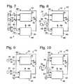
- FIG. 6is a schematic view of another example of a fuel processing assembly that may be used with feedstock delivery systems according to the present disclosure.
- FIG. 7is a schematic view of a fuel processing assembly according to the present disclosure in which the hydrogen-producing region and the feedstock delivery system both receive the same liquid carbon-containing feedstock.
- FIG. 8is a schematic view showing a variation of the fuel processing assembly of FIG. 7 , with a carbon-containing feedstock being delivered to the hydrogen-producing region and the burner assembly from the same supply stream.
- FIG. 9is a schematic view of a fuel processing assembly according to the present disclosure in which the hydrogen-producing region and the burner assembly both receive fuel, or feed, streams containing water and a liquid carbon-containing feedstock.
- FIG. 10is a schematic view showing a variation of the fuel processing assembly of FIG. 9 ) with the hydrogen-producing region and the burner assembly both receiving fuel, or feed, streams containing water and a carbon-containing feedstock from the same supply stream.
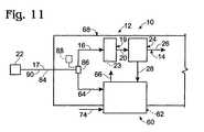
- FIG. 11is a schematic view showing another variation of the fuel processing assemblies of FIGS. 9 and 10 .
- Fuel processing assembly 10includes a fuel processor 12 that is adapted to produce a product hydrogen stream 14 containing hydrogen gas, and preferably at least substantially pure hydrogen gas, from one or more feed streams 16 .
- Feed stream 16may include at least one carbon-containing feedstock 18 .
- Fuel processor 12includes any suitable device, or combination of devices, that is adapted to produce hydrogen gas from feed stream(s) 16 .
- fuel processor 12includes a hydrogen-producing region 19 , in which an output stream 20 containing hydrogen gas is produced by utilizing any suitable hydrogen-producing mechanism(s).
- Output stream 20includes hydrogen gas as at least a majority component.
- Output stream 20may include one or more additional gaseous components, and thereby may be referred to as a mixed gas stream that contains hydrogen gas as its majority component.
- suitable mechanisms for producing hydrogen gas from feed stream(s) 16 delivered by feedstock delivery system 22include steam reforming and autothermal reforming, in which reforming catalysts are used to produce hydrogen gas from a feed stream 16 containing a carbon-containing feedstock 18 and water 17 .
- Other suitable mechanisms for producing hydrogen gasinclude pyrolysis and catalytic partial oxidation of a carbon-containing feedstock, in which case the feed stream does not contain water.
- suitable carbon-containing feedstocks 18include at least one hydrocarbon or alcohol.
- suitable hydrocarbonsinclude methane, propane, natural gas, diesel, kerosene, gasoline and the like.
- suitable alcoholsinclude methanol, ethanol, and polyols, such as ethylene glycol and propylene glycol.
- feedstock delivery system 22is adapted to draw or otherwise receive a liquid carbon-containing feedstock from a supply, or source, and to deliver a feed stream 16 containing the feedstock for use in at least the hydrogen-producing region of the fuel processing assembly.
- Feedstock delivery system 22may utilize any suitable delivery mechanism, such as a positive displacement or other suitable pump or mechanism for propelling liquid fluid streams.
- An illustrative, non-exclusive example of a feedstock delivery system 22 according to the present disclosureis shown in FIG. 2 and is adapted to deliver feed stream 16 to hydrogen-producing region 19 of the fuel processor 12 of fuel processing assembly 10 .
- feedstock delivery system 22includes a pump assembly 100 that includes at least one pump 102 .
- Pump 102includes an inlet 106 and an outlet 108 , with the inlet being in fluid communication with a feedstock supply, or source, 112 , and the outlet being in fluid communication with fuel processor 12 .
- Pump 102further includes a working portion, or pumping mechanism, 109 that is located generally between the pump's intake and outlet.
- Pump 102is adapted to draw or otherwise receive a liquid stream 110 from supply 112 and to emit a liquid stream 116 .
- feedstock delivery system 22may be described as being adapted to pump a liquid stream containing at least one feedstock for hydrogen-producing region 19 from a liquid feedstock supply.
- Stream 110may be referred to as an inlet stream or an intake stream, and stream 116 may be referred to as an outlet stream.
- Pump 102may be powered by any suitable power source; illustrative, non-exclusive examples of which include a component of hydrogen-producing fuel cell system 42 , such as the subsequently described fuel cell stack 40 and/or energy storage device 52 . Additional illustrative examples include a power supply that is independent of power output produced by the fuel cell system, such as an external, or dedicated, battery, an electrical grid, etc. While not required, pump 102 may be a single-speed, or single-output, pump that is adapted to either be in an on, or active, configuration in which the pump is receiving liquid stream 110 and emitting liquid stream 116 , or an off, or unpowered, configuration in which the pump is not emitting stream 116 . The actual output of the pump will vary with the voltage of the power output delivered to the pump, which may tend to vary.
- pump assembly 100includes at least one pump. Accordingly, it is within the scope of the present disclosure that pump assembly 100 may include a single pump 102 or more than one pump 102 . When the pump assembly includes more than one pump, the pumps may cooperate to draw liquid stream 110 and/or emit outlet stream 116 . Additionally or alternatively, the pumps may each be adapted to draw a liquid stream 110 from the same or different sources 112 and/or to each emit an outlet stream 116 therefrom.
- Supply 112includes any suitable type and/or number of reservoirs and/or other sources from which the liquid stream may be drawn or otherwise received by an inlet 106 of a pump 102 of pump assembly 100 .
- suitable supplies 112include tanks, canisters, and other liquid vessels, which may or may not be pressurized.
- Liquid stream 110contains at least one component of feed stream 16 , such as water 17 and/or a carbon-containing feedstock 18 .
- stream 110 and/or supply 112contain at least two different components of feed stream 16 , such as water 17 and a liquid carbon-containing feedstock 18 .
- stream 110may include a single component of feed stream 16 , may contain more than one component of feed stream 16 , and/or may include all of the component(s) of feed stream 16 .
- the components of feed stream(s) 16may also be referred to as feedstocks from which hydrogen-producing region 19 produces hydrogen gas.
- liquid outlet stream 116may form feed stream 16 .
- at least a portion of liquid stream 116may additionally or alternatively be recycled to a location upstream of the pump's intake 106 , such as to supply 112 or to the fluid conduit through which stream 110 flows from supply 112 to pump 102 .
- upstream and downstreamare measured with respect to the direction of fluid flow through the corresponding stream.
- the recycled portion 120 of liquid stream 116is shown in a solid line being delivered back to supply 112 and in a dashed line being delivered to a fluid conduit containing stream 110 . It is further within the scope of the present disclosure that recycle stream 120 may be recycled directly to the pump, such as at or proximate inlet 106 , as indicated in FIG. 2 with a dash-dot line.
- the feedstock delivery systemmay be described as including an intake conduit 130 through which liquid stream 110 is drawn or otherwise received from supply 112 to pump 102 .
- the feedstock delivery systemfurther includes an outlet, or output, conduit 132 through which stream 116 is emitted from the pump's outlet 108 .
- the output conduitis in fluid communication with a delivery conduit 134 , through which at least a portion of stream 116 may be delivered to hydrogen-producing region 19 as at least a portion of feed stream 16 .
- Feedstock delivery systems 22further include a recycle conduit 136 that defines a fluid flow path that establishes fluid communication between the delivery conduit and a portion of the feedstock delivery system that is upstream of the pump's working portion 109 .
- This portion of the recycle conduitmay be referred to as the higher pressure region of the recycle conduit, and the portion of the recycle conduit downstream of the flow restrictor may be referred to as a lower pressure region of the recycle conduit.
- the recycle conduitmay be described as including a first portion that extends in fluid communication between the outlet conduit and the flow restructure and defines a liquid flow path therebetween, and a second portion that extends in fluid communication between the flow restrictor and supply 112 , inlet conduit 130 or another portion of the feedstock delivery system that is upstream from the working portion of the pump.
- the second portion of the recycle conduitsimilarly defines a liquid flow path between the flow restrictor and this upstream portion of the feedstock delivery system.
- the outlet conduitbranches to establish fluid communication, or connections, with the recycle and delivery conduits.
- the fluid conduits described hereinmay include any suitable structure that defines a flow path for the liquid or other fluid streams described herein. Accordingly, the conduits should be formed from a suitable material, construction, and size for the fluid streams traveling therethrough and the operating conditions encountered thereby.
- the conduitshave been schematically illustrated in FIG. 3 , and it is within the scope of the present disclosure that they may (but are not required to) include, or be in communication with, additional structures and/or components, such as sensors, valves, flow-control devices, and the like.
- pump 102is adapted to continuously draw stream 110 thereto and to emit liquid stream 116 therefrom, with it being within the scope of the present disclosure that the pump may be adapted to deliver a greater flow rate of stream 116 than is desired, or in some embodiments even able to be present in feed stream 16 .
- the pumpmay be described as providing an output stream having a greater flow rate of liquid than the flow rate of feed stream 16 that is produced therefrom and delivered to the hydrogen-producing region (or other portion) of fuel processor 12 .
- the pumpmay be described as being configured to provide excess liquid, or excess flow rate, in output stream 116 , thereby providing a flow of liquid that forms recycle stream 120 .
- the pumpmay be configured to maintain a constant output regardless of the hydrogen demand, or requirements of the hydrogen-producing region, at least when the hydrogen-producing region is in a hydrogen-producing operating state.
- the pumpmay be configured to maintain a flow rate of liquid feedstock that exceeds the hydrogen-producing region's maximum demand for the feedstock (i.e., the demand for the feedstock when the hydrogen-producing region is at its maximum rated production rate and/or when the hydrogen-producing region is producing sufficient hydrogen gas to produce a power output at the maximum rated power output of the fuel cell stack).
- the feedstock delivery systemmay be adapted to provide an output stream that has a flow rate that is at least 10%, at least 25%, or even at least 50% greater than the amount of feedstock required by the hydrogen-producing region.
- the excess feedstockis not wasted, and instead is recycled through the feedstock delivery system, where it may be reused or returned to the feedstock supply.
- feedstock delivery system 22further includes a flow restrictor 140 and a pressure-actuated valve 150 .
- Flow restrictor 140is adapted to reduce, or restrict, the cross-sectional area of recycle conduit 136 .
- flow restrictor 140may define a cross-sectional area for conduit 136 that is smaller than the cross-sectional area of delivery conduit 134 . Accordingly, liquid stream 116 may be biased to flow through delivery conduit 134 , and thereby to hydrogen-producing region 19 , when the pressure in the hydrogen-producing region and/or delivery conduit 134 is less than the pressure in the recycle stream (at least between outlet conduit 132 and flow restrictor 140 ).
- flow restrictor 140is adapted to create backpressure against recycle stream 120 flowing through the flow restrictor and through recycle conduit 136 back to the feedstock supply or other location upstream of the pump's working portion.
- the selected amount of backpressure created by the orificemay vary according to a variety of factors, such as one or more of user preferences, the size of the orifice, the shape of the orifice, the flow rate of liquid emitted by the pump assembly, the size of the delivery and recycle conduits, the composition and properties of the feed stream, etc.
- the flow restrictoris sized or otherwise configured to provide, or maintain, a pressure that is greater than the selected, or desired, delivery pressure of feed stream 16 to hydrogen-producing region 19 and less than the subsequently described threshold delivery pressure and/or threshold recycle pressure.
- Flow restrictor 140may include any suitable structure that is configured to restrict the flow path of the recycle stream through recycle conduit 136 .
- the flow restrictormay include an orifice 142 having an opening 144 of smaller cross-sectional area than a portion of recycle conduit 136 upstream of the orifice and/or of smaller cross-sectional area than delivery conduit 134 .
- An example of such an orificeis schematically illustrated in FIG. 3 .
- Orifice 142may be referred to as a restrictive orifice.
- Orifice 142may have an opening having a fixed, or non-adjustable, size.
- the flow restrictormay include an orifice having a variable, or adjustable, opening size.
- the orificeWhen the orifice is configured to permit adjustment of its orifice size, it may be configured for manual adjustment of the orifice size, such as responsive to user inputs to a manual control element and/or responsive to electronic or other command signals from a controller or other portion of the fuel processing assembly and/or fuel cell system.
- Pressure-actuated valve 150is adapted to selectively permit the recycle stream to bypass the flow restrictor and thereby not be subjected to the backpressure created by the restrictive orifice 142 or other flow restrictor 140 and yet still be able to be returned to the supply or other portion of the feedstock delivery system that is upstream of the pump's working portion.
- suitable pressure-actuated valvesinclude pressure relief valves and check valves that are fluidly connected to as described herein, namely, to selectively restrict and permit liquid flow to a bypass conduit that enables the liquid to bypass the flow restrictor. As graphically indicated in FIG.
- pressure-actuated valve 150is in fluid communication with a bypass conduit 152 through which at least a portion of recycle stream 120 may selectively flow as a bypass stream 154 from a position upstream of the flow restrictor to a position downstream of the flow restrictor.
- the pressure-actuated valveis adapted to selectively permit at least a portion of the recycle stream to flow from conduit 132 through the recycle conduit and back to supply 112 or inlet conduit 110 without having to flow through the flow restrictor.
- the pressure-actuated valveis schematically illustrated at the juncture between the bypass conduit and the recycle conduit upstream of the flow restrictor.
- the pressure-actuated valvemay be located at any suitable location where it selectively permits and restricts flow to the flow restrictor, with the flow being diverted through the bypass conduit when the pressure-actuated valve restricts its flow to the flow restrictor.
- FIG. 3illustrates that the pressure-actuated valve may be located at an intermediate position along the bypass conduit (i.e., anywhere between the inlet and outlet of the bypass conduit). It is also within the scope of the present disclosure that the valve may be located at the inlet or exit of the conduit.
- Pressure-actuated valve 150is normally adapted, or biased, to restrict flow through bypass conduit 152 when the pressure in recycle stream 136 upstream of the flow restrictor (i.e., between output conduit 132 and flow restrictor 140 ) is less than a threshold recycle pressure.
- This configurationmay be referred to as the closed, or flow-restricting, configuration of the pressure-actuated valve.
- the pressure-actuated valveis adapted to automatically permit liquid from upstream of orifice 140 to flow through bypass conduit 152 .
- the pressure-actuated valveWhen the pressure reaches (or exceeds) this threshold recycle pressure and the pressure-actuated valve is (automatically) configured to its actuated configuration responsive thereto, at least a portion of recycle stream 120 may flow through the bypass conduit, thereby reducing the pressure of the liquid upstream of the flow restrictor. This may also reduce the pressure of the feed stream delivered by the feedstock delivery system.
- the threshold recycle pressuremay be the same as the maximum, or threshold, delivery pressure that is acceptable for feed stream 16 . However, it is also within the scope of the present disclosure that these pressures are not the same.
- the threshold recycle pressuremay be selected to be less than the threshold delivery pressure, such as by a determined increment, to provide a buffer or pressure differential between the pressure at which the pressure-actuated valve is designed to permit flow through the bypass conduit (and thereby reduce the pressure in the delivery and other associated streams) and the maximum pressure at which the delivery conduit and/or fuel processing assembly is designed, or desired, to receive the feed stream.
- At least the hydrogen-producing region of fuel processing assembly 10may be designed to operate at an elevated pressure, such as a pressure of at least 50 psi.
- an elevated pressuresuch as a pressure of at least 50 psi.
- this regionmay also be designed to operate at an elevated pressure.
- the particular maximum and minimum operating pressures for a particular fuel processing assemblywill tend to vary according to a variety of possible factors.
- Illustrative examples of such factorsmay include, but may not be limited to, the hydrogen-producing reaction utilized in hydrogen-producing region 19 , the composition of feed stream 16 , the viscosity of the liquid in feed stream 16 , the delivery conduit construction, size, and/or configuration, the construction of the fuel processing assembly, the pressure requirements of the fuel processing assembly and/or fuel cell system downstream from the hydrogen-producing region, design choices and tolerances, etc.
- some fuel processing assembliesmay be designed to maintain an elevated pressure in at least the hydrogen-producing region, and optionally at least one purification region thereof by utilizing a restrictive orifice or other suitable flow restrictor downstream of the hydrogen-producing region, and optionally downstream of a purification region that is also preferably maintained at an elevated pressure.
- the amount of liquid (i.e., the percentage of recycle stream 120 ) that flows through conduit 152may vary within the scope of the present disclosure.
- the entirety of the stream that forms recycle stream 120may flow through the bypass conduit when the pressure-actuated valve is in its actuated, or flow-permitted, configuration.
- some of stream 120may also flow through orifice 142 or other flow restrictor 140 even in periods in which the pressure-actuated valve is in this actuated configuration.
- pressure-actuated valve 150may include a valve, or valve member, 156 and a biasing mechanism 158 that is adapted to bias the valve from its actuated configuration to its closed configuration.
- Biasing mechanism 150may include any suitable structure or device adapted to provide the above-described biasing and yet permit the pressure-actuated valve to be configured to its actuated configuration when the threshold recycle pressure is reached, or exceeded.
- An illustrative, non-exclusive example of a suitable biasing mechanismis a spring or other resilient member that exerts a biasing force against the valve member in a direction that opposes the force exerted upon the pressure-actuated valve by the liquid in the recycle stream upstream of the flow restrictor.
- the liquid stream upstream from the flow restrictormay exert a force that urges the pressure-actuated valve from its closed configuration to its actuated configuration.
- This forceis applied against the bias of, or the force exerted by, biasing mechanism 158 .
- the pressure-actuated valveis configured to its actuated configuration. Otherwise, when the stream pressure exerts a force to the pressure-actuated valve that is less than the force applied by the biasing mechanism, the pressure-actuated valve is adapted to remain in its closed configuration.
- Biasing mechanism 158may also function as a pressure detector, or pressure sensor, that is adapted to detect when the pressure of the liquid stream emitted by the pump assembly exceeds a threshold pressure, such as a threshold recycle or delivery pressure. Specifically, when the pressure of the liquid, as applied against the biasing mechanism, is sufficient to overcome the force exerted by the biasing mechanism, then the threshold pressure is exceeded. Accordingly, the biasing mechanism may be adapted to exert a biasing force that sets or corresponds to the threshold pressure, such as the threshold recycle or delivery pressure.
- Biasing mechanism 158is preferably further adapted to automatically return the pressure-actuated valve to its closed configuration, such as when the pressure detected thereby (or applied thereto) decreases to below the threshold recycle pressure, when the pressure decreases to a level that is not sufficient to overcome the biasing force exerted by the biasing mechanism, and/or after a predetermined time period has elapsed since the pressure-actuated valve was configured to its actuated configuration.
- the pressure-actuated valveis configured to remain in its actuated configuration, once configured thereto, for at least a predetermined minimum time period.
- the pressure-actuated valvemay be configured to automatically transition between its actuated and closed configurations responsive entirely to the forces exerted thereto by the liquid steam and the biasing mechanism.
- FIGS. 2 and 3illustrate feedstock delivery systems 22 that include a flow restrictor and a pressure-actuated valve associated with the recycle stream of the feedstock delivery system.
- orifice 142 or another flow restrictor 140is adapted to create backpressure that thereby urges, or biases, the output stream from the pump assembly to flow through delivery conduit 134 toward the hydrogen-producing region of the fuel processing assembly.
- the orifice or other flow restrictorbecome clogged or otherwise fail, then the amount of backpressure created by the flow restrictor will increase and the portion of liquid outlet stream 116 that flows therethrough to form recycle stream 136 will decrease or even become zero, which corresponds to when there is no flow through the flow restrictor.
- this pressurecontinues to increase, i.e., if the hydrogen-generation assembly remains in operation, there is a potential for injury or damage.
- pressures that exceed the threshold delivery pressure and/or threshold recycle pressuremay damage pump 102 or one or more portions of the fuel processing assembly.
- the pressure in at least output stream 116 , and typically feed stream 16 , and the portion of recycle stream 120 upstream from the flow restrictorwill continue to increase because the pump is configured to emit a greater flow of output stream 116 than is being consumed by hydrogen-producing region 19 . Because the orifice or other flow restrictor is not able to permit the excess liquid, or sufficient quantities of the excess liquid, to flow therethrough to form recycle stream 120 , the pressure will increase.
- the above-described feedstock delivery systemsalso include a pressure-actuated valve 150 , the pressure is prevented from increasing beyond a threshold recycle or delivery pressure.
- the pressure-actuated valveWhen the pressure-actuated valve is actuated, the pressure will decrease, at least until the pressure-actuated valve returns to its closed configuration. Should the flow restrictor continue to be clogged or otherwise inoperational or only partially operational, the pressure may begin to increase again, with the pressure-actuated valve again transitioning to its actuated configuration should the pressure again increase to or beyond the corresponding threshold pressure.
- a feedstock delivery system 22may not include both flow restrictor 140 and pressure-actuated valve 150 .
- the feedstock delivery systemmay include a flow restrictor 40 , such as described herein, without a pressure-actuated valve (and accordingly without bypass conduit 152 ).
- the feedstock delivery systemmay include a pressure-actuated valve 150 , such as descried herein, without a flow restrictor that creates backpressure on the outlet stream and which is selectively bypassed using the pressure-actuated valve.
- bypass conduitwould not be present, and the pressure-actuated valve would selectively create backpressure to the outlet (and delivery) streams in its closed configuration, in which flow of the recycle stream is restricted by the pressure-actuated valve.
- the pressure-actuated valveis transitioned or otherwise urged to its actuated configuration, in which at least a portion of the outlet stream is recycled to supply 112 or another portion of the delivery system upstream of the pump's working portion.
- system 22 and/or fuel processing assemblies and/or fuel cell systems containing feedstock delivery system 22may include other suitable mechanisms for detecting and reacting to pressures that near or exceed a selected threshold pressure.
- systems that include a controllermay include a pressure sensor that is adapted to measure the pressure in output stream 116 , upstream of flow restrictor 140 , or in another suitable location, with the controller being adapted to control the operation of at least feedstock delivery system 22 responsive to a pressure that exceeds or nears a selected threshold.
- feedstock delivery system 22is implemented without a flow restrictor, then pressure-actuated valve 150 will still be able to selectively reduce the pressure in output stream 116 , feed stream 16 , etc., responsive to when the pressure in these streams exceeds a selected threshold pressure, such as the above-discussed threshold recycle pressure or threshold delivery pressure. Because such a feedstock delivery system 22 does not include a flow restrictor that establishes some backpressure within system 22 while also permitting a recycle stream to flow therethrough, the pressure in the system will tend to oscillate. More specifically, the liquid pressure will tend to increase as the pump emits a greater flow rate of liquid than is consumed in hydrogen-producing region 19 .
- a selected threshold pressuresuch as the above-discussed threshold recycle pressure or threshold delivery pressure.
- FIG. 1While a single feed stream 16 is shown in FIG. 1 , it is within the scope of the disclosure that more than one stream 16 may be used and that these streams may contain the same or different feedstocks. This is schematically illustrated by the inclusion of a second feed stream 16 in dashed lines in FIG. 1 . Similarly, FIG. 1 also illustrates in dashed lines that that each feed stream 16 may (but is not required to be associated with a different feedstock delivery system 22 , or portions thereof. For example, when more than one feedstock delivery system 22 is utilized, the systems may (but are not required to) draw at least a portion of their outlet streams from a common supply. When feed stream 16 contains two or more components, such as a carbon-containing feedstock and water, the components may be delivered in the same or different feed streams.
- feed stream 16contains two or more components, such as a carbon-containing feedstock and water, the components may be delivered in the same or different feed streams.
- the fuel processorwhen the fuel processor is adapted to produce hydrogen gas from a carbon-containing feedstock and water, these components are typically delivered in separate streams, and optionally (at least until both streams are vaporized or otherwise gaseous), when they are not miscible with each other, such as shown in FIG. 1 by reference numerals 17 and 18 pointing to different feed streams.
- the feedstockis typically, but is not required to be, delivered with the water component of feed stream 16 , such as shown in FIG. 1 by reference numerals 17 and 18 pointing to the same feed stream 16 .
- the fuel processorreceives a feed stream containing water and a water-soluble alcohol, such as methanol, these components may be premixed and delivered as a single stream.
- a reforming feed streammay contain approximately 25-75 vol % methanol or ethanol or another suitable water-miscible carbon-containing feedstock, and approximately 25-75 vol % water.
- the streamswill typically contain approximately 50-75 vol % methanol and approximately 25-50 vol % water.
- Streams containing ethanol or other water-miscible alcoholswill typically contain approximately 25-60 vol % alcohol and approximately 40-75 vol % water.
- An example of a particularly well-suited feed stream for hydrogen-generating assemblies that utilize steam reforming or autothermal reforming reactionscontains 69 vol % methanol and 31 vol % water, although other compositions and liquid carbon-containing feedstocks may be used without departing from the scope of the present disclosure.
- such a feed stream that contains both water and at least one carbon-containing feedstockmay be used as the feed stream for hydrogen-producing region 19 and as a combustible fuel stream for a heating assembly that is adapted to heat at least the hydrogen-producing region of the fuel processing assembly.
- Steam reformingis one example of a hydrogen-producing mechanism that may be employed in hydrogen-producing region 19 in which feed stream 16 comprises water and a carbon-containing feedstock.
- hydrogen-producing region 19contains a suitable steam reforming catalyst 23 , as indicated in dashed lines in FIG. 1 .
- the fuel processormay be referred to as a steam reformer
- hydrogen-producing region 19may be referred to as a reforming region
- output, or mixed gas, stream 20may be referred to as a reformate stream.
- reforming region 19refers to any hydrogen-producing region utilizing a steam reforming hydrogen-producing mechanism.
- suitable steam reforming catalystsinclude copper-zinc formulations of low temperature shift catalysts and a chromium formulation sold under the trade name KMA by Sud-Chemie, although others may be used.
- the other gases that are typically present in the reformate streaminclude carbon monoxide, carbon dioxide, methane, steam, and/or unreacted carbon-containing feedstock.
- a suitable hydrogen-producing reactionthat may be utilized in hydrogen-producing region 19 is autothermal reforming, in which a suitable autothermal reforming catalyst is used to produce hydrogen gas from water and a carbon-containing feedstock in the presence of air.
- the fuel processorfurther includes an air delivery assembly 67 that is adapted to deliver an air stream to the hydrogen-producing region, as indicated in dashed lines in FIG. 1 .
- Autothermal hydrogen-producing reactionsutilize a primary endotheimic reaction that is utilized in conjunction with an exothermic partial oxidation reaction, which generates heat within the hydrogen-producing region upon initiation of the initial hydrogen-producing reaction.
- hydrogen-producing steam reformerstypically operate at temperatures in the range of 200° C. and 900° C. Temperatures outside of this range are within the scope of the disclosure. Steam and autothermal reformers also tend to operate at elevated pressures, such as pressures in the range of 50 and 1000 psi, although pressures outside of this range may be used and are within the scope of the present disclosure.
- the carbon-containing feedstockis methanol
- the steam reforming reactionwill typically operate in a temperature range of approximately 200-500° C.
- Illustrative subsets of this rangeinclude 350-450° C., 375-425° C., and 375-400° C.
- a temperature range of approximately 400-900° C.will typically be used for the steam reforming reaction.
- Illustrative subsets of this rangeinclude 750-850° C., 725-825° C., 650-750° C., 700-800° C., 700-900° C., 500-800° C., 400-600° C., and 600-800° C.
- the hydrogen-producing regionto include two or more zones, or portions, each of which may be operated at the same or at different temperatures.
- the hydrogen-production fluidincludes a hydrocarbon
- the fuel processing systemmay alternatively be described as including two or more hydrogen producing regions.
- suitable heating assemblies for use with fuel processing assemblies according to the present disclosureare disclosed in U.S. patent application Ser. Nos. 10/407,500 and 10/412,709, as well as in U.S. patent application Ser. No. 11/226,810, which was filed on Sep.
- the fuel processormay utilize a process that inherently produces sufficiently pure hydrogen gas.
- product hydrogen stream 14may be formed directly from output stream 20 .
- output stream 20will be a mixed gas stream that contains hydrogen gas as a majority component along with other gases.
- the output stream 20may be substantially pure hydrogen but still contain concentrations of one or more non-hydrogen components that are harmful or otherwise undesirable in the application for which the product hydrogen stream is intended to be used.
- Fuel processing assembly 10may (but is not required to) further include a purification region 24 , in which a hydrogen-rich stream 26 is produced from the output, or mixed gas, stream.
- Hydrogen-rich stream 26contains at least one of a greater hydrogen concentration than output stream 20 and a reduced concentration of one or more of the other gases or impurities that were present in the output stream.
- Purification region 24is schematically illustrated in FIG. 1 , where output stream 20 is shown being delivered to an optional purification region 24 .
- at least a portion of hydrogen-rich stream 26forms product hydrogen stream 14 .
- hydrogen-rich stream 26 and product hydrogen stream 14may be the same stream and have the same compositions and flow rates.
- some of the purified hydrogen gas in hydrogen-rich stream 26may be stored for later use, such as in a suitable hydrogen storage assembly, and/or consumed by the fuel processing assembly.
- Purification region 24may, but is not required to, produce at least one byproduct stream 28 .
- byproduct stream 28may be exhausted, sent to a burner assembly or other combustion source, used as a heated fluid stream, stored for later use, or otherwise utilized, stored or disposed of. It is within the scope of the disclosure that byproduct stream 28 may be emitted from the purification region as a continuous stream responsive to the delivery of output stream 20 to the purification region, or intermittently, such as in a batch process or when the byproduct portion of the output stream is retained at least temporarily in the purification region.
- Purification region 24includes any suitable device, or combination of devices, that are adapted to reduce the concentration of at least one component of output stream 20 .
- hydrogen-rich stream 26will have a greater hydrogen concentration than output, or mixed gas, stream 20 .
- the hydrogen-rich streamwill have a reduced concentration of one or more non-hydrogen components that were present in output stream 20 , yet have the same, or even a reduced overall hydrogen concentration as the output stream.
- certain impurities, or non-hydrogen componentsare more harmful than others.
- carbon monoxidemay damage a fuel cell stack if it is present in even a few parts per million, while other non-hydrogen components that may be present in stream 20 , such as water, will not damage the stack even if present in much greater concentrations. Therefore, in such an application, a suitable purification region may not increase the overall hydrogen concentration, but it will reduce the concentration of a non-hydrogen component that is harmful, or potentially harmful, to the desired application for the product hydrogen stream.
- suitable devices for purification region 24include one or more hydrogen-selective membranes 30 , chemical carbon monoxide removal assemblies 32 , and pressure swing adsorption systems 38 . It is within the scope of the disclosure that purification region 24 may include more than one type of purification device, and that these devices may have the same or different structures and/or operate by the same or different mechanisms. As discussed, hydrogen-producing fuel processing assembly 10 may include at least one restrictive orifice or other flow restrictor downstream of at least one purification region, such as associated with one or more of the product hydrogen stream, hydrogen-rich stream, and/or byproduct stream.
- Hydrogen-selective membranes 30are permeable to hydrogen gas, but are at least substantially, if not completely, impermeable to other components of output stream 20 .
- Membranes 30may be formed of any hydrogen-permeable material suitable for use in the operating environment and parameters in which purification region 24 is operated. Examples of suitable materials for membranes 30 include palladium and palladium alloys, and especially thin films of such metals and metal alloys. Palladium alloys have proven particularly effective, especially palladium with 35 wt % to 45 wt % copper. A palladium-copper alloy that contains approximately 40 wt % copper has proven particularly effective, although other relative concentrations and components may be used within the scope of the disclosure.
- Hydrogen-selective membranesare typically formed from a thin foil that is approximately 0.001 inches thick. It is within the scope of the present disclosure, however, that the membranes may be formed from other hydrogen-permeable and/or hydrogen-selective materials, including metals and metal alloys other than those discussed above as well as non-metallic materials and compositions, and that the membranes may have thicknesses that are greater or less than discussed above. For example, the membrane may be made thinner, with commensurate increase in hydrogen flux. Examples of suitable mechanisms for reducing the thickness of the membranes include rolling, sputtering and etching. A suitable etching process is disclosed in U.S. Pat. No. 6,152,995, the complete disclosure of which is hereby incorporated by reference for all purposes.
- Chemical carbon monoxide removal assemblies 32are devices that chemically react carbon monoxide and/or other undesirable components of stream 20 , if present in output stream 20 , to form other compositions that are not as potentially harmful.
- Examples of chemical carbon monoxide removal assembliesinclude water-gas shift reactors and other devices that convert carbon monoxide to carbon dioxide, and methanation catalyst beds that convert carbon monoxide and hydrogen to methane and water. It is within the scope of the disclosure that fuel processing assembly 10 may include more than one type and/or number of chemical removal assemblies 32 .
- PSAPressure swing adsorption
- gaseous impuritiesare removed from output stream 20 based on the principle that certain gases, under the proper conditions of temperature and pressure, will be adsorbed onto an adsorbent material more strongly than other gases. Typically, it is the impurities that are adsorbed and removed from output stream 20 .
- the success of using PSA for hydrogen purificationis due to the relatively strong adsorption of common impurity gases (such as CO, CO 2 , hydrocarbons including CH 4 , and N 2 ) on the adsorbent material. Hydrogen adsorbs only very weakly and so hydrogen passes through the adsorbent bed while the impurities are retained on the adsorbent material.
- common impurity gasessuch as CO, CO 2 , hydrocarbons including CH 4 , and N 2
- Impurity gasessuch as NH 3 , H 2 S, and H 2 O adsorb very strongly on the adsorbent material and are removed from stream 20 along with other impurities. If the adsorbent material is going to be regenerated and these impurities are present in stream 20 , purification region 24 preferably includes a suitable device that is adapted to remove these impurities prior to delivery of stream 20 to the adsorbent material because it is more difficult to desorb these impurities.
- Adsorption of impurity gasesoccurs at elevated pressure. When the pressure is reduced, the impurities are desorbed from the adsorbent material, thus regenerating the adsorbent material.
- PSAis a cyclic process and requires at least two beds for continuous (as opposed to batch) operation.
- suitable adsorbent materialsthat may be used in adsorbent beds are activated carbon and zeolites, especially 5 ⁇ (5 angstrom) zeolites.
- the adsorbent materialis commonly in the form of pellets and it is placed in a cylindrical pressure vessel utilizing a conventional packed-bed configuration. Other suitable adsorbent material compositions, forms, and configurations may be used.
- PSA system 38also provides an example of a device for use in purification region 24 in which the byproducts, or removed components, are not directly exhausted from the region as a gas stream concurrently with the purification of the output stream, Instead, these byproduct components are removed when the adsorbent material is regenerated or otherwise removed from the purification region.
- purification region 24is shown within fuel processor 12 . It is within the scope of the disclosure that region 24 , when present, may alternatively be separately located downstream from the fuel processor, as is schematically illustrated in dash-dot lines in FIG. 1 . It is also within the scope of the disclosure that purification region 24 may include portions within and external fuel processor 12 .
- the fuel processorIn the context of a fuel processor, or fuel processing assembly, that is adapted to produce a product hydrogen stream that will be used as a feed, or fuel, stream for a fuel cell stack, the fuel processor preferably is adapted to produce substantially pure hydrogen gas, and even more preferably, the fuel processor is adapted to produce pure hydrogen gas.
- substantially pure hydrogen gasis greater than 90% pure, preferably greater than 95% pure, more preferably greater than 99% pure, and even more preferably greater than 99.5% pure.
- Suitable fuel processors and fuel processing assembliesincluding illustrative (non-exclusive) examples of components and configurations therefor for producing streams of at least substantially pure hydrogen gas are disclosed in U.S. Pat. Nos.
- fuel processor 12is shown including a shell 68 in which at least the hydrogen-producing region, and optionally the purification region, is contained.
- Shell 68which also may be referred to as a housing, enables the components of the steam reformer or other fuel processing mechanism to be moved as a unit. It also protects the components of fuel processor 12 from damage by providing a protective enclosure and reduces the heating demand of the fuel processing assembly because the components of the fuel processor may be heated as a unit.
- Shell 68may, but does not necessarily, include insulating material 70 , such as a solid insulating material, blanket insulating material, and/or an air-filled cavity. It is within the scope of the disclosure, however, that the fuel processor may be formed without a housing or shell.
- fuel processor 12When fuel processor 12 includes insulating material 70 , the insulating material may be internal the shell, external the shell, or both. When the insulating material is external a shell containing the above-described reforming and/or purification regions, fuel processor 12 further may include an outer cover or jacket 72 external the insulation, as schematically illustrated in FIG. 1 . It is within the scope of the present disclosure that the fuel processing assembly may be implemented with a different shell, with a shell that includes additional components of the fuel processing assembly, including feedstock delivery system 22 (or portions thereof), and/or includes additional components of the fuel cell system. It is also within the scope of the present disclosure that a fuel processing assembly 10 may not include a shell 68 .
- one or more of the components of fuel processing assembly 10may either extend beyond the shell or be located external at least shell 68 .
- purification region 24may be located external shell 68 , such as with the purification region being coupled directly to the shell (as schematically illustrated in FIG. 5 ) or being spaced-away from the shell but in fluid communication therewith by suitable fluid-transfer conduits (as indicated in dash-dot lines in FIG. 1 ).
- a portion of hydrogen-producing region 19(such as portions of one or more reforming catalyst beds) may extend beyond the shell, such as indicated schematically with a dashed line representing an alternative shell configuration in FIG. 1 .
- product hydrogen stream 14may be used in a variety of applications, including applications where high purity hydrogen gas is utilized.
- An example of such an applicationis as a fuel, or feed, stream for a fuel cell stack.
- a fuel cell stackis a device that produces an electrical potential from a source of protons, such as hydrogen gas, and an oxidant, such as oxygen gas.
- a fuel cell stackmay be adapted to receive at least a portion of product hydrogen stream 14 and a stream of oxygen (which is typically delivered as an air stream), and to produce an electric current therefrom. This is schematically illustrated in FIG. 4 , in which a fuel cell stack is indicated at 40 and produces an electric current, which is schematically illustrated at 41 .
- the resulting systemmay be referred to as a fuel cell system 42 because it includes a fuel cell stack and a source of fuel for the fuel cell stack. It is within the scope of the present disclosure that fuel processors and heating assemblies according to the present disclosure may be used in applications that do not include a fuel cell stack.
- compositions that may damage the fuel cell stacksuch as carbon monoxide and carbon dioxide, may be removed from the hydrogen-rich stream, if necessary, such as by purification region 24 .
- concentration of carbon monoxideis preferably less than 10 ppm (parts per million).
- concentration of carbon monoxideis less than 5 ppm, and even more preferably, less than 1 ppm.
- concentration of carbon dioxidemay be greater than that of carbon monoxide. For example, concentrations of less than 25% carbon dioxide may be acceptable in some embodiments.
- the concentrationis less than 10%, and even more preferably, less than 1%. While not required, especially preferred concentrations are less than 50 ppm.
- the acceptable minimum concentrations presented hereinare illustrative examples, and concentrations other than those presented herein may be used and are within the scope of the present disclosure. For example, particular users or manufacturers may require minimum or maximum concentration levels or ranges that are different than those identified herein.
- Fuel cell stack 40contains at least one, and typically multiple, fuel cells 44 that are adapted to produce an electric current from an oxidant, such as air, oxygen-enriched air, or oxygen gas, and the portion of the product hydrogen stream 14 delivered thereto.
- a fuel cell stacktypically includes multiple fuel cells joined together between common end plates 48 , which contain fluid delivery/removal conduits, although this construction is not required to all embodiments.
- suitable fuel cellsinclude proton exchange membrane (PEM) fuel cells and alkaline fuel cells. Others include solid oxide fuel cells, phosphoric acid fuel cells, and molten carbonate fuel cells.
- the electric current produced by stack 40may be used to satisfy the energy demands, or applied load, of at least one associated energy-consuming device 46 .
- devices 46include, but should not be limited to, motor vehicles, recreational vehicles, construction or industrial vehicles, boats or other seacraft, tools, lights or lighting assemblies, appliances (such as household or other appliances), households or other dwellings, offices or other commercial establishments, computers, signaling or communication equipment, battery chargers, etc.
- fuel cell stack 40may be used to satisfy the power requirements of fuel cell system 42 , which may be referred to as the balance-of-plant power requirements of the fuel cell system.
- device 46is schematically illustrated in FIG. 4 and is meant to represent one or more devices, or collection of devices, that are adapted to draw electric current from the fuel cell system.
- Fuel cell stack 40may receive all of product hydrogen stream 14 . Some or all of stream 14 may additionally, or alternatively, be delivered, via a suitable conduit, for use in another hydrogen-consuming process, burned for fuel or heat, or stored for later use.
- a hydrogen storage device 50is shown in dashed lines in FIG. 4 .
- Device 50is adapted to store at least a portion of product hydrogen stream 14 . For example, when the demand for hydrogen gas by stack 40 is less than the hydrogen output of fuel processor 12 , the excess hydrogen gas may be stored in device 50 .
- suitable hydrogen storage devicesinclude hydride beds and pressurized tanks.
- a benefit of fuel processing assembly 10 or fuel cell system 42 including a supply of stored hydrogenis that this supply may be used to satisfy the hydrogen requirements of stack 40 , or the other application for which stream 14 is used, in situations when fuel processor 12 is not able to meet these hydrogen demands. Examples of these situations include when the fuel processor is starting up from a cold, or inactive state, ramping up (being heated and/or pressurized) from an idle state, offline for maintenance or repair, and when the fuel cell stack or application is demanding a greater flow rate of hydrogen gas than the maximum available production from the fuel processor. Additionally or alternatively, the stored hydrogen may also be used as a combustible fuel stream to heat the fuel processing assembly or fuel cell system. Fuel processing assemblies that are not directly associated with a fuel cell stack may still include at least one hydrogen-storage device, thereby enabling the product hydrogen streams from these fuel processing assemblies to also be stored for later use.
- Fuel cell system 42may also include a battery 52 or other suitable electricity-storing device that is adapted to store the electric potential, or power output, produced by stack 40 . Similar to the above discussion regarding excess hydrogen, fuel cell stack 40 may produce a power output in excess of that necessary to satisfy the load exerted, or applied, by device 46 , including the load required to power fuel cell system 42 . In further similarity to the above discussion of excess hydrogen gas, this excess power output may be used in other applications outside of the fuel cell system and/or stored for later use by the fuel cell system. For example, the battery or other storage device may provide power for use by system 42 during startup or other applications in which the system is not producing electricity and/or hydrogen gas. In FIG.
- flow-regulating structuresare generally indicated at 54 and schematically represent any suitable manifolds, valves, controllers, switches and the like for selectively delivering hydrogen and the fuel cell stack's power output to device 50 and battery 52 , respectively, and to draw the stored hydrogen and stored power output therefrom.
- fuel processing assembliesmay include a heating assembly 60 that is adapted to heat at least the hydrogen-producing region, or reforming region, 19 of the fuel processor.
- heating assembly 60includes a burner assembly 62 and may be referred to as a combustion-based, or combustion-driven, heating assembly.
- the heating assembly 60is adapted to receive at least one fuel stream 64 and to combust the fuel stream in the presence of air to provide a hot combustion stream 66 that may be used to heat at least the hydrogen-producing region 19 of the fuel processor.
- Stream 66may also be referred to as a heated exhaust stream.
- airmay be delivered to the heating assembly via a variety of mechanisms.
- an air stream 74is shown in solid lines; however, it is within the scope of the disclosure for the air stream to additionally or alternatively be delivered to the heating assembly with at least one of the fuel streams 64 for the heating assembly 60 and/or drawn from the environment within which the heating assembly is utilized.
- combustion stream 66may additionally or alternatively be used to heat other portions of the fuel processing assembly and/or fuel cell systems with which heating assembly 60 is used. It is also within the scope of the present disclosure that other configurations and types of heating assemblies 60 may be utilized. As an illustrative example, a heating assembly 60 may be an electrically powered heating assembly that is adapted to heat at least the hydrogen-producing region of the fuel processing assembly by generating heat using at least one heating element, such as a resistive heating element. Therefore, it is not required that heating assembly 60 receive and combust a combustible fuel stream to heat hydrogen-producing region 19 to a suitable hydrogen-producing temperature.
- heating assembly 60is shown in an overlapping relationship with fuel processor 12 to graphically represent that it is within the scope of the disclosure that the heating assembly may be located partially or completely within fuel processor 12 , such as being at least partially within shell 68 , and/or that at least a portion, or all, of the heating assembly may be located external the fuel processor. In this latter embodiment, the hot combustion gases from the burner assembly will be delivered via suitable heat transfer conduits to the fuel processor or other portion of the system(s) to be heated.
- fuel processing assemblies 10may include a vaporization region 69 that is adapted to receive a liquid feed stream 16 (or a liquid component of feed stream 16 , such as a stream of water 17 or a stream of a liquid carbon-containing feedstock 18 ) and to vaporize the feed stream (or portion thereof) prior to delivery to hydrogen-producing region 19 of fuel processor 12 .
- heated combustion stream 66 from the heating assemblymay be used to vaporize the feed stream in vaporization region 69 and/or otherwise heat the feed stream.
- fuel processor 12may be constructed without a vaporization region and/or that the fuel processor is adapted to receive a feed stream that is gaseous or that has already been vaporized. It is also within the scope of the present disclosure that vaporization region 69 , when present, extends partially or completely outside of shell 68 (when present).
- Fuel processors 12 , heating assemblies 60 , and feedstock delivery systems 22 according to the present disclosuremay be configured in any of the arrangements described, illustrated and/or incorporated herein. In some embodiments, features or aspects from one or more of the above described configurations may be combined with each other and/or with additional features described herein. For example, it is within the scope of the present disclosure that fuel processing assemblies 10 that include at least one purification region 24 may (but are not required to) house the hydrogen-producing region 19 and at least a portion of the purification region together in a common housing, with this housing optionally being located within the shell 68 of the fuel processor. This is schematically illustrated in FIG.
- reference numeral 25generally indicates a hydrogen-producing region 19 of a fuel processor, with the hydrogen-producing region being contained within a housing, or vessel, 27 that contains at least the reforming (or other) catalyst 23 used to produce the mixed gas stream from the feed stream that is delivered to the hydrogen-producing region.
- shell 27may, but is not required to, also include a purification region 24 .
- the purification regionwhen present in the housing, may include one or more hydrogen-selective membranes 30 and/or a chemical carbon monoxide removal assembly 32 .
- region 25may be described as a hydrogen-producing and purifying region when it contains both a hydrogen-producing region 19 and a purification region 24 . It is within the scope of the disclosure that any of the regions 19 and 24 described, illustrated and/or incorporated herein may be used in region 25 .
- region 25does not include a purification region, it may simply be described as a hydrogen-producing region 19 that includes a housing 27 .
- housing 27includes a purification region 24
- the fuel processing assemblymay include one or more additional purification regions (such as which may include the same or different purification devices/mechanisms) external (i.e., downstream from) housing 27 .
- the fuel processing assemblies illustrated hereinthereby include a hydrogen-producing region that is contained in a housing, with this housing optionally also containing a purification region.
- vaporization region 69when present may extend partially or completely within housing 27 .
- a liquid-phase carbon-containing feedstock 84may be used for both carbon-containing feedstock portion 18 of feed stream 16 for reforming region 19 and carbon-containing feedstock portion 65 of fuel stream 64 for heating assembly 60 , such as schematically illustrated in FIG.
- FIG. 7also provides a graphical illustration of a hydrogen-producing fuel processing assembly that includes more than one feedstock delivery system 22 , such as a delivery system 22 that is adapted to deliver a feed stream containing water 17 , a feed stream containing carbon-containing feedstock 18 , and/or a feedstock delivery system 22 that is adapted to deliver fuel stream 64 .
- a feedstock delivery system 22that is adapted to deliver a feed stream containing water 17 , a feed stream containing carbon-containing feedstock 18 , and/or a feedstock delivery system 22 that is adapted to deliver fuel stream 64 .
- the previous example of three feedstock delivery to systemsmay additionally or alternatively be implemented as a single feedstock delivery system 22 , such as which may include more than one pump and/or produce more than one outlet stream.
- not all liquid streams to the fuel processing assemblyare delivered by a feedstock delivery system 22 . Instead, one or more of the streams may be delivered by a different mechanism or delivery system.
- liquid carbon-containing feedstock 84is delivered to both heating assembly 60 and hydrogen-producing region 19 .
- FIG. 7has been shown in a fragmentary view because fuel processor 12 may have a wide variety of configurations, such as configurations that do not include a purification region, that utilize more than one type or number of purification mechanism, etc. It is intended that the fragmentary fuel processor shown in FIG. 7 (and subsequent figures) schematically represents any of these configurations, as well as any of the steam reformers and other fuel processors described, illustrated and/or incorporated herein.
- FIG. 8is similar to FIG. 7 , except that the liquid carbon-containing feedstock 84 is delivered as a single stream to valve assembly 86 , in which the carbon-containing feedstock is selectively delivered to at least one of the heating assembly and the hydrogen-producing region.
- Valve assembly 86may include any suitable structure for selectively dividing the stream of carbon-containing feedstock between the heating assembly and the hydrogen-producing region. The range of possible configurations includes the heating assembly receiving all of the carbon-containing feedstock, the hydrogen-producing region receiving all of the carbon-containing feedstock, or both the heating assembly and the hydrogen-producing region receiving carbon-containing feedstock.
- the distribution of the carbon-containing feedstockdepends at least in part upon the particular carbon-containing feedstock being used, whether byproduct stream 28 is also used as a fuel for at least a portion of heating assembly 60 , and the particular mode of operation of the fuel processor, such as an idle mode, a startup mode, or a hydrogen-producing mode.
- the distribution of liquid carbon-containing feedstock 84 between the hydrogen-producing region and the heating assemblymay be manually controlled. However, in many embodiments, it may be desirable for the distribution to be predetermined and/or at least partially automated, such as by including a controller 88 that selectively regulates the delivery of feedstock 84 between the hydrogen-producing region and the heating assembly.
- a controller 88that selectively regulates the delivery of feedstock 84 between the hydrogen-producing region and the heating assembly.
- An example of a suitable controller for a steam reforming fuel processoris disclosed in U.S. Pat. No. 6,383,670, the complete disclosure of which is hereby incorporated by reference.
- controller 88 and/or valve assembly 86may be configured to allow a predetermined initial volume of carbon-containing feedstock into heating assembly 60 , as will be discussed in greater detail herein.
- feed stream 16may be at least substantially, and typically entirely, comprised of a mixture of water and a liquid-phase carbon-containing feedstock 84 that is preferably miscible in, or with, water.
- a single (composite) feed stream 90 containing water 17 and carbon-containing feedstock 84can be consumed as both the hydrogen-producing feed stream 16 for the reforming reaction, as well as the heating assembly fuel stream 64 .
- feed stream 16 and fuel stream 64both containing the same liquid carbon-containing feedstock 84 and water 17 , with the carbon-containing feedstock preferably being miscible in water.
- Thisis schematically illustrated in FIGS. 9 and 10 , in which this composite stream is indicated at 90 .
- Streams 16 and 64may have nearly, or completely, identical compositions, and may be entirely formed from stream 90 . It is within the scope of the disclosure, however, that at least one of streams 16 and 64 may have at least one additional component or additional amount of water or carbon-containing feedstock added thereto prior to consumption of the stream by the heating assembly or hydrogen-producing region. Similarly, it is within the scope of the present disclosure that additional streams may deliver additional components or additional amounts of water or carbon-containing feedstock to the heating assembly or the fuel processor.
- composite feed stream 90may be selectively delivered to heating assembly 60 and hydrogen-producing region 19 in separate streams from the same source or from different sources, as schematically illustrated in FIG. 9 .
- a single composite feed stream 90may be delivered to the fuel processing assembly, and more specifically to a valve assembly 86 , where the stream is selectively divided between the heating assembly and the hydrogen-producing region.
- a controller 88which may be a manual controller or a computerized or other electronic controller or preprogrammed controller, is also shown in dashed lines in FIG. 10 .
- Controller 88may be located internal or external fuel processor 12 , and/or may include both internal and external components.
- the relative amounts of water 17 and liquid carbon-containing feedstock 84 in composite feed stream 90may vary within the scope of the present disclosure.
- the ratiomay depend upon such factors as the particular carbon-containing feedstock being used, the hydrogen-producing mechanism being used in the fuel processor, user preferences, the catalyst being utilized, the demand for hydrogen gas, the efficiency of the reforming catalyst, etc.
- the relative concentrations of these componentsmay be expressed in terms of a ratio of water to carbon.
- feedstock 84is methanol
- feedstock 84is a 1:1 molar ratio of steam to carbon has proven effective.
- feedstock 84is ethanol
- a ratio of 2-3:1has proven effective.
- feedstock 84is a hydrocarbon
- a ratio of approximately 3:1is typically used.
- the illustrative ratios described aboveare not meant to be exclusive ratios within the scope of the disclosure, and others, including greater and lesser ratios, may be used.
- valve assembly 86may be located either internal or external fuel processor 12 .
- FIG. 11also illustrates that when the fuel processor includes or is otherwise associated with a purification region 24 that produces a gaseous byproduct stream 28 , the gaseous byproduct stream 28 may be delivered to the heating assembly to be used as a gaseous fuel for the heating assembly.
- This gaseous fuelmay supplement the liquid fuel discussed above (such as carbon-containing feedstock 84 or composite feed stream 90 ), or may itself contain sufficient heating value for certain steam reformers or other fuel processors and/or certain operating configurations of the fuel processors.
- FIGS. 1-11Illustrative examples of hydrogen-producing fuel cell systems 42 , hydrogen-producing fuel processing assemblies 10 , and feedstock delivery systems 22 have been schematically illustrated in FIGS. 1-11 . These systems may include additional components, such as air/oxidant supplies and delivery systems, heat exchange assemblies and/or sources, controllers, sensors, valves and other flow controllers, power management modules, etc. It is within the scope of the present disclosure to selectively include one or more of these components. Similarly, although a single fuel processor 12 and/or a single fuel cell stack 40 are shown in FIGS. 1-11 , it is within the scope of the disclosure that more than one of either or both of these components may be used.
- feedstock delivery systems, and hydrogen-producing fuel processing and fuel cell systems containing the same that are disclosed hereinare applicable to the hydrogen- and energy-production industries, including the fuel cell industries.
Landscapes
- Chemical & Material Sciences (AREA)
- Chemical Kinetics & Catalysis (AREA)
- Organic Chemistry (AREA)
- Engineering & Computer Science (AREA)
- Life Sciences & Earth Sciences (AREA)
- Combustion & Propulsion (AREA)
- Inorganic Chemistry (AREA)
- General Health & Medical Sciences (AREA)
- Health & Medical Sciences (AREA)
- Manufacturing & Machinery (AREA)
- Sustainable Development (AREA)
- Sustainable Energy (AREA)
- Electrochemistry (AREA)
- General Chemical & Material Sciences (AREA)
- Hydrogen, Water And Hydrids (AREA)
- Fuel Cell (AREA)
Abstract
Description
Claims (21)
Priority Applications (1)
| Application Number | Priority Date | Filing Date | Title |
|---|---|---|---|
| US12/574,151US7736596B2 (en) | 2005-09-16 | 2009-10-06 | Self-regulating feedstock delivery systems and hydrogen-generating fuel processing assemblies and fuel cell systems incorporating the same |
Applications Claiming Priority (2)
| Application Number | Priority Date | Filing Date | Title |
|---|---|---|---|
| US11/228,637US7601302B2 (en) | 2005-09-16 | 2005-09-16 | Self-regulating feedstock delivery systems and hydrogen-generating fuel processing assemblies and fuel cell systems incorporating the same |
| US12/574,151US7736596B2 (en) | 2005-09-16 | 2009-10-06 | Self-regulating feedstock delivery systems and hydrogen-generating fuel processing assemblies and fuel cell systems incorporating the same |
Related Parent Applications (1)
| Application Number | Title | Priority Date | Filing Date |
|---|---|---|---|
| US11/228,637ContinuationUS7601302B2 (en) | 2005-09-16 | 2005-09-16 | Self-regulating feedstock delivery systems and hydrogen-generating fuel processing assemblies and fuel cell systems incorporating the same |
Publications (2)
| Publication Number | Publication Date |
|---|---|
| US20100021353A1 US20100021353A1 (en) | 2010-01-28 |
| US7736596B2true US7736596B2 (en) | 2010-06-15 |
Family
ID=37882661
Family Applications (2)
| Application Number | Title | Priority Date | Filing Date |
|---|---|---|---|
| US11/228,637Active2028-04-13US7601302B2 (en) | 2005-09-16 | 2005-09-16 | Self-regulating feedstock delivery systems and hydrogen-generating fuel processing assemblies and fuel cell systems incorporating the same |
| US12/574,151Expired - LifetimeUS7736596B2 (en) | 2005-09-16 | 2009-10-06 | Self-regulating feedstock delivery systems and hydrogen-generating fuel processing assemblies and fuel cell systems incorporating the same |
Family Applications Before (1)
| Application Number | Title | Priority Date | Filing Date |
|---|---|---|---|
| US11/228,637Active2028-04-13US7601302B2 (en) | 2005-09-16 | 2005-09-16 | Self-regulating feedstock delivery systems and hydrogen-generating fuel processing assemblies and fuel cell systems incorporating the same |
Country Status (1)
| Country | Link |
|---|---|
| US (2) | US7601302B2 (en) |
Cited By (10)
| Publication number | Priority date | Publication date | Assignee | Title |
|---|---|---|---|---|
| US8961627B2 (en) | 2011-07-07 | 2015-02-24 | David J Edlund | Hydrogen generation assemblies and hydrogen purification devices |
| US9187324B2 (en) | 2012-08-30 | 2015-11-17 | Element 1 Corp. | Hydrogen generation assemblies and hydrogen purification devices |
| US9605224B2 (en) | 2014-11-12 | 2017-03-28 | Element 1 Corp. | Refining assemblies and refining methods for rich natural gas |
| US9777237B2 (en) | 2014-11-12 | 2017-10-03 | Element 1 Corp. | Refining assemblies and refining methods for rich natural gas |
| US9828561B2 (en) | 2014-11-12 | 2017-11-28 | Element 1 Corp. | Refining assemblies and refining methods for rich natural gas |
| US9914641B2 (en) | 2012-08-30 | 2018-03-13 | Element 1 Corp. | Hydrogen generation assemblies |
| US10717040B2 (en) | 2012-08-30 | 2020-07-21 | Element 1 Corp. | Hydrogen purification devices |
| US10870810B2 (en) | 2017-07-20 | 2020-12-22 | Proteum Energy, Llc | Method and system for converting associated gas |
| US11738305B2 (en) | 2012-08-30 | 2023-08-29 | Element 1 Corp | Hydrogen purification devices |
| US12187612B2 (en) | 2021-06-15 | 2025-01-07 | Element 1 Corp | Hydrogen generation assemblies |
Families Citing this family (19)
| Publication number | Priority date | Publication date | Assignee | Title |
|---|---|---|---|---|
| CA2582151C (en) | 2004-10-31 | 2009-07-07 | Idatech, Llc | Hydrogen generation and energy production assemblies |
| ES2482791T3 (en)* | 2005-09-16 | 2014-08-04 | Dcns Sa | Raw material supply system of self-regulated feed and hydrogen generator fuel processing assembly incorporating the same |
| US8262752B2 (en) | 2007-12-17 | 2012-09-11 | Idatech, Llc | Systems and methods for reliable feedstock delivery at variable delivery rates |
| US20090280367A1 (en)* | 2008-05-12 | 2009-11-12 | Clearedge Power, Inc. | Extraction of Energy From Used Cooking Oil |
| US20100055518A1 (en) | 2008-08-26 | 2010-03-04 | Idatech, Llc | Hydrogen-producing assemblies, fuel cell systems including the same, methods of producing hydrogen gas, and methods of powering an energy-consuming device |
| US9017436B2 (en) | 2008-08-26 | 2015-04-28 | Dcns | Fuel processing systems with thermally integrated componentry |
| US8557451B2 (en)* | 2009-04-10 | 2013-10-15 | Protonex Technology Corporation | Fuel processor for fuel cell systems |
| US8920996B2 (en) | 2010-05-11 | 2014-12-30 | Dcns | Systems and methods for regulating fuel cell air flow during low loads or cold temperature operation |
| US8449649B2 (en) | 2010-05-11 | 2013-05-28 | Idatech, Llc | Systems and methods for starting up pressure swing adsorption assemblies and hydrogen-producing fuel processing systems including the same |
| FR2960450B1 (en)* | 2010-05-25 | 2013-02-22 | Inst Francais Du Petrole | PROCESS FOR ANAEROBIC PRODUCTION OF HYDROGEN |
| US8920732B2 (en) | 2011-02-15 | 2014-12-30 | Dcns | Systems and methods for actively controlling steam-to-carbon ratio in hydrogen-producing fuel processing systems |
| US9548504B2 (en) | 2012-01-24 | 2017-01-17 | University Of Connecticut | Utilizing phase change material, heat pipes, and fuel cells for aircraft applications |
| JP6219492B2 (en) | 2013-03-14 | 2017-10-25 | エレメント・ワン・コーポレーション | Hydrogen production assembly and hydrogen purification equipment |
| JP6566639B2 (en) | 2015-01-05 | 2019-08-28 | 大阪瓦斯株式会社 | Method for operating hydrogen production apparatus and hydrogen production apparatus |
| US11667202B2 (en) | 2017-03-08 | 2023-06-06 | A3 Labs LLC | Energy source supply systems, energy source supply devices, and related methods |
| TWI724933B (en) | 2018-01-04 | 2021-04-11 | 美商1號組件公司 | Hydrogen purification devices |
| US11618676B2 (en) | 2020-10-23 | 2023-04-04 | H2 Powertech, Llc | Systems and methods for increasing the hydrogen permeance of hydrogen-separation membranes in situ |
| US12283727B2 (en) | 2022-08-16 | 2025-04-22 | H2 Powertech, Llc | Hydrogen-producing fuel cell systems and methods of operating the same |
| US20240271833A1 (en)* | 2023-02-15 | 2024-08-15 | General Electric Company | Systems, methods, and apparatus for cooling superconducting motors |
Citations (246)
| Publication number | Priority date | Publication date | Assignee | Title |
|---|---|---|---|---|
| US1306221A (en) | 1919-06-10 | Etom emiis | ||
| US1782824A (en) | 1928-05-18 | 1930-11-25 | Chemical Construction Corp | Catalytic apparatus |
| US1848466A (en) | 1932-03-08 | of terre haute | ||
| US2132151A (en) | 1935-03-13 | 1938-10-04 | Pennsylvania Petroleum Res Cor | Apparatus for treating mineral oils |
| US2450804A (en) | 1943-12-09 | 1948-10-05 | Phillips Petroleum Co | Catalyst chamber construction |
| US2609059A (en) | 1948-06-29 | 1952-09-02 | Hydrocarbon Research Inc | Mass diffusion process and apparatus |
| US2824620A (en) | 1955-09-12 | 1958-02-25 | Universal Oil Prod Co | Purification of hydrogen utilizing hydrogen-permeable membranes |
| US3094391A (en) | 1960-04-22 | 1963-06-18 | Kellogg M W Co | Hydrocarbon conversion |
| US3144312A (en) | 1961-06-06 | 1964-08-11 | Mertens Carl | Catalytic conversion plant for the continuous generation of gases of any kind out of ydrocarbons |
| US3208198A (en) | 1962-07-26 | 1965-09-28 | Engelhard Ind Inc | Method for hydrogen diffusion |
| US3336730A (en) | 1964-11-17 | 1967-08-22 | Union Carbide Corp | Hydrogen continuous production method and apparatus |
| US3338681A (en) | 1963-12-18 | 1967-08-29 | Union Carbide Corp | Apparatus for hydrogen generation |
| US3344586A (en) | 1965-06-22 | 1967-10-03 | Engelhard Ind Inc | Gas separation apparatus |
| US3350176A (en) | 1964-03-24 | 1967-10-31 | Engelhard Ind Inc | Hydrogen generator |
| US3356538A (en) | 1964-09-29 | 1967-12-05 | Gen Electric | Electrodeposited ion exchange membrane and method of forming |
| US3368329A (en) | 1965-08-10 | 1968-02-13 | Eguchi Takashi | Hydrogen purification apparatus |
| US3428476A (en) | 1965-06-22 | 1969-02-18 | Engelhard Min & Chem | Method for producing hydrogen diffusion cells |
| US3439474A (en) | 1967-08-17 | 1969-04-22 | Union Carbide Corp | Method for hydrogen separation and purification |
| US3447288A (en) | 1965-08-23 | 1969-06-03 | Prototeck Inc | Gas-diffusion assembly including thin hydrogen-permeable impervious foil |
| US3450500A (en) | 1965-08-03 | 1969-06-17 | United Aircraft Corp | Method for catalytically reforming hydrogen-containing carbonaceous feed-stocks by simultaneous abstractions through a membrane selectively permeable to hydrogen |
| US3469944A (en) | 1968-05-13 | 1969-09-30 | Joseph P Bocard | Process and apparatus for the manufacture of hydrogen for fuel cells |
| US3469372A (en) | 1965-06-18 | 1969-09-30 | Mitsubishi Gas Chemical Co | Hydrogen permeable membrane and hydrogen permeating assembly |
| US3486301A (en) | 1968-08-05 | 1969-12-30 | Engelhard Min & Chem | Hydrogen diffusion apparatus |
| US3520803A (en) | 1968-12-24 | 1970-07-21 | Ionics | Membrane fluid separation apparatus and process |
| US3522019A (en) | 1965-08-03 | 1970-07-28 | United Aircraft Corp | Apparatus for generating hydrogen from liquid hydrogen - containing feedstocks |
| US3524819A (en) | 1967-03-03 | 1970-08-18 | Lummus Co | Steam reforming of hydrocarbons |
| US3534531A (en) | 1963-08-31 | 1970-10-20 | Japan Pure Hydrogen Co Ltd | Assembly of pure gas permeating separator |
| US3564819A (en) | 1970-02-24 | 1971-02-23 | Gen Electric | Membrane package construction |
| US3589171A (en) | 1969-08-25 | 1971-06-29 | California Inst Of Techn | Gas analysis system and palladium tube separator therefor |
| US3655448A (en) | 1969-05-22 | 1972-04-11 | United Aircraft Corp | Hydrogen generator desulfurizer employing feedback ejector |
| US3665680A (en) | 1970-12-18 | 1972-05-30 | Engelhard Min & Chem | Hydrogen diffusion apparatus |
| US3713270A (en) | 1971-05-24 | 1973-01-30 | Nat Res Dev | Hydrogen diffusion membranes |
| US3761382A (en) | 1972-06-21 | 1973-09-25 | Triangle Environment Corp | Ers and the like apparatus for generating purifying and delivering hydrogen for analyz |
| US3782904A (en) | 1971-10-07 | 1974-01-01 | Nasa | Compact hydrogenator |
| US3787038A (en) | 1970-01-04 | 1974-01-22 | P Tesner | Reformer for firing reverberatory furnace and method of operating said reformer |
| US3791106A (en) | 1970-09-24 | 1974-02-12 | California Inst Of Techn | Gas analysis systems and palladium tube separator therefor |
| US3837146A (en) | 1971-09-09 | 1974-09-24 | Rhone Poulenc Sa | Separating apparatus particularly suitable for gas permeation and in pervaporation |
| US3839110A (en) | 1973-02-20 | 1974-10-01 | Bell Telephone Labor Inc | Chemical etchant for palladium |
| US3849076A (en) | 1972-06-21 | 1974-11-19 | V Gryaznov | Catalytic reactor for carrying out conjugate chemical reactions |
| US3881891A (en) | 1973-02-05 | 1975-05-06 | Viktor Alexeevich Goltsov | Method for preparation of super-high purity hydrogen |
| US3881897A (en) | 1972-11-24 | 1975-05-06 | Rhone Poulenc Sa | Apparatus for separating fluids |
| US3920416A (en) | 1973-12-26 | 1975-11-18 | California Inst Of Techn | Hydrogen-rich gas generator |
| US3955941A (en) | 1973-08-20 | 1976-05-11 | California Institute Of Technology | Hydrogen rich gas generator |
| US3972695A (en) | 1975-05-12 | 1976-08-03 | Trienco, Inc. | Hydrogen purifier |
| US3980452A (en) | 1973-09-14 | 1976-09-14 | Metallgesellschaft Aktiengesellschaft | Process for supplying heat to chemical reactions |
| US3982910A (en) | 1974-07-10 | 1976-09-28 | The United States Of America As Represented By The Administrator Of The National Aeronautics And Space Administration | Hydrogen-rich gas generator |
| US4003343A (en) | 1975-04-04 | 1977-01-18 | Phillips Petroleum Company | Method and apparatus for maintaining the operating temperature in a device for reducing engine exhaust pollutants |
| US4003725A (en) | 1975-05-12 | 1977-01-18 | Trienco, Inc. | Apparatus for purifying hydrogen gas |
| US4056373A (en) | 1976-05-12 | 1977-11-01 | Resource Systems, Inc. | Hydrogen-purification apparatus with palladium-alloy filter coil |
| US4078985A (en) | 1975-11-21 | 1978-03-14 | Nippon Soken, Inc. | Hydrogen generator |
| US4084934A (en) | 1972-02-05 | 1978-04-18 | Mitsubishi Precision Co., Ltd. | Combustion apparatus |
| US4098959A (en) | 1976-12-27 | 1978-07-04 | United Technologies Corporation | Fuel cell fuel control system |
| US4098960A (en) | 1976-12-27 | 1978-07-04 | United Technologies Corporation | Fuel cell fuel control system |
| US4127393A (en) | 1975-01-13 | 1978-11-28 | British Gas Corporation | Method and apparatus for vaporizing hydrocarbon based liquids |
| US4132668A (en) | 1977-04-06 | 1979-01-02 | Gryaznov Vladimir M | Method of preparing a hydrogen-permeable membrane catalyst on a base of palladium or its alloys for the hydrogenation of unsaturated organic compounds |
| US4134739A (en) | 1976-04-05 | 1979-01-16 | Siemens Aktiengesellschaft | Starting device for a reformed gas generator |
| US4175165A (en) | 1977-07-20 | 1979-11-20 | Engelhard Minerals & Chemicals Corporation | Fuel cell system utilizing ion exchange membranes and bipolar plates |
| US4197152A (en) | 1979-03-14 | 1980-04-08 | Gte Sylvania Incorporated | Attaching self-supporting emissive film to cathode support |
| US4214969A (en) | 1979-01-02 | 1980-07-29 | General Electric Company | Low cost bipolar current collector-separator for electrochemical cells |
| US4238403A (en) | 1975-03-03 | 1980-12-09 | Imperial Chemical Industries Limited | Methanol synthesis process |
| US4243536A (en) | 1977-12-01 | 1981-01-06 | Kilcher-Chemie Ag | Cross-flow filtration apparatus |
| US4248688A (en) | 1979-09-04 | 1981-02-03 | International Business Machines Corporation | Ion milling of thin metal films |
| US4254086A (en) | 1978-12-27 | 1981-03-03 | Sanders Alfred P | Endothermal water decomposition unit for producing hydrogen and oxygen |
| US4302177A (en) | 1976-03-26 | 1981-11-24 | The M. W. Kellogg Company | Fuel conversion apparatus and method |
| US4313013A (en) | 1980-08-01 | 1982-01-26 | Phillips Petroleum Company | Palladium or a palladium alloy hydrogen diffusion membrane treated with a volatile compound of silicon is used to separate hydrogen from a mixture of it with a hydrocarbon |
| US4315893A (en) | 1980-12-17 | 1982-02-16 | Foster Wheeler Energy Corporation | Reformer employing finned heat pipes |
| US4319923A (en) | 1979-12-26 | 1982-03-16 | Western Electric Co., Inc. | Recovery of gold and/or palladium from an iodide-iodine etching solution |
| US4329157A (en) | 1978-05-16 | 1982-05-11 | Monsanto Company | Inorganic anisotropic hollow fibers |
| US4331520A (en) | 1979-10-26 | 1982-05-25 | Prototech Company | Process for the recovery of hydrogen-reduced metals, ions and the like at porous hydrophobic catalytic barriers |
| US4349613A (en) | 1979-12-06 | 1982-09-14 | Varta Batterie Aktiengesellschaft | Method and apparatus for electrochemical energy production |
| US4381641A (en) | 1980-06-23 | 1983-05-03 | Gulf Research & Development Company | Substoichiometric combustion of low heating value gases |
| US4387434A (en) | 1980-10-24 | 1983-06-07 | Process Technologies, Inc. | Intelligent field interface device for fluid storage facility |
| US4400182A (en) | 1980-03-18 | 1983-08-23 | British Gas Corporation | Vaporization and gasification of hydrocarbon feedstocks |
| US4417905A (en) | 1975-09-29 | 1983-11-29 | British Gas Corporation | Gas making |
| US4422911A (en) | 1982-06-14 | 1983-12-27 | Prototech Company | Method of recovering hydrogen-reduced metals, ions and the like at porous catalytic barriers and apparatus therefor |
| US4430304A (en) | 1981-11-13 | 1984-02-07 | The United States Of America As Represented By The United States Department Of Energy | Slab reformer |
| US4444158A (en) | 1982-09-03 | 1984-04-24 | Conoco Inc. | Alcohol dissociation process for automobiles |
| US4466253A (en) | 1982-12-23 | 1984-08-21 | General Electric Company | Flow control at flash tank of open cycle vapor compression heat pumps |
| US4468235A (en) | 1979-02-15 | 1984-08-28 | Hill Eugene F | Hydrogen separation using coated titanium alloys |
| US4472176A (en) | 1983-08-01 | 1984-09-18 | Resource Systems, Inc. | Apparatus and method for the production of pure hydrogen from a hydrogen-containing crude gas |
| US4473622A (en) | 1982-12-27 | 1984-09-25 | Chludzinski Paul J | Rapid starting methanol reactor system |
| US4483690A (en) | 1982-06-07 | 1984-11-20 | Texaco Development Corporation | Apparatus for production of synthesis gas from heavy hydrocarbon fuels containing high metal concentrations |
| US4504447A (en) | 1981-11-13 | 1985-03-12 | The United States Of America As Represented By The United States Department Of Energy | Slab reformer |
| US4533607A (en) | 1984-12-06 | 1985-08-06 | United Technologies Corporation | Process for removing electrolyte vapor from fuel cell exhaust gas |
| US4553981A (en) | 1984-02-07 | 1985-11-19 | Union Carbide Corporation | Enhanced hydrogen recovery from effluent gas streams |
| US4567857A (en) | 1980-02-26 | 1986-02-04 | The United States Of America As Represented By The Administrator Of The National Aeronautics And Space Administration | Combustion engine system |
| US4589891A (en) | 1983-09-08 | 1986-05-20 | Kernforschungsanlage Julich Gesellschaft Mit Beschrankter Haftung | Hydrogen permeatin membrane, process for its manufacture and use |
| US4613436A (en) | 1984-10-31 | 1986-09-23 | Separex Corporation | Membrane assembly for fluid separations-disk |
| US4642273A (en) | 1983-05-19 | 1987-02-10 | Mitsubishi Denki Kabushiki Kaisha | Reformer reaction control apparatus for a fuel cell |
| US4644751A (en) | 1985-03-14 | 1987-02-24 | Massachusetts Institute Of Technology | Integrated fuel-cell/steam plant for electrical generation |
| US4650814A (en) | 1984-03-07 | 1987-03-17 | Keller Arnold P | Process for producing methanol from a feed gas |
| US4654063A (en) | 1984-12-21 | 1987-03-31 | Air Products And Chemicals, Inc. | Process for recovering hydrogen from a multi-component gas stream |
| US4655797A (en) | 1983-09-08 | 1987-04-07 | Kernforschungsanlage Julich Gesellschaft Mit Beschrankter Haftung | Fine screen and fine screen stack, their use and process for the manufacture of fine screens |
| US4657828A (en) | 1985-04-10 | 1987-04-14 | Fuji Electric Company Ltd. | Fuel cell system |
| US4659634A (en) | 1984-12-18 | 1987-04-21 | Struthers Ralph C | Methanol hydrogen fuel cell system |
| US4670359A (en) | 1985-06-10 | 1987-06-02 | Engelhard Corporation | Fuel cell integrated with steam reformer |
| US4684581A (en) | 1986-07-10 | 1987-08-04 | Struthers Ralph C | Hydrogen diffusion fuel cell |
| US4693945A (en) | 1985-04-22 | 1987-09-15 | Hitachi, Ltd. | Power generator containing fuel cell |
| US4699637A (en) | 1983-09-08 | 1987-10-13 | Kernforschungsanlage Julich Gesellschaft Mit Beschrankter Haftung | Hydrogen permeation membrane |
| US4713234A (en) | 1984-06-30 | 1987-12-15 | Kernforschungsanlage Julich Gesellschaft Mit Beschrankter Haftung | Process and apparatus for conversion of water vapor with coal or hydrocarbon into a product gas |
| US4751151A (en) | 1986-12-08 | 1988-06-14 | International Fuel Cells Corporation | Recovery of carbon dioxide from fuel cell exhaust |
| CA1238866A (en) | 1982-09-13 | 1988-07-05 | Johnson Matthey Public Limited Company | Diffusion cell |
| US4781241A (en) | 1987-08-27 | 1988-11-01 | International Fuel Cells Corporation | Heat exchanger for fuel cell power plant reformer |
| US4788004A (en) | 1986-05-27 | 1988-11-29 | Imperial Chemical Industries Plc | Catalytic process |
| US4810485A (en) | 1986-08-25 | 1989-03-07 | Institute Of Gas Technology | Hydrogen forming reaction process |
| US4820594A (en) | 1986-02-07 | 1989-04-11 | Hitachi, Ltd. | Method of starting fuel cell power generation system |
| US4838897A (en) | 1985-04-10 | 1989-06-13 | Hitachi, Ltd. | Reformer |
| US4849187A (en) | 1987-03-31 | 1989-07-18 | Toyo Engineering Corporation | Steam reforming apparatus |
| US4865624A (en) | 1987-06-29 | 1989-09-12 | Nippon Sanso Kabushiki Kaisha | Method for steam reforming methanol and a system therefor |
| US4880040A (en) | 1988-09-16 | 1989-11-14 | Raymond Pierson | Liquid petroleum confinement system |
| US4904455A (en) | 1985-06-27 | 1990-02-27 | Stone & Webster Engineering Corporation | Production of synthesis gas using convective reforming |
| US4904548A (en) | 1987-08-03 | 1990-02-27 | Fuji Electric Co., Ltd. | Method for controlling a fuel cell |
| US4946667A (en) | 1985-06-10 | 1990-08-07 | Engelhard Corporation | Method of steam reforming methanol to hydrogen |
| US4981676A (en) | 1989-11-13 | 1991-01-01 | Minet Ronald G | Catalytic ceramic membrane steam/hydrocarbon reformer |
| US4999107A (en) | 1988-10-17 | 1991-03-12 | Eurodia S.A. | Separator frame for a two-fluid exchanger device |
| EP0434562A1 (en) | 1989-12-20 | 1991-06-26 | MEDAL 1.p. | Process and apparatus for removing carbon monoxide from gaseous mixture containing hydrogen |
| US5030661A (en) | 1988-03-24 | 1991-07-09 | Imperial Chemical Industries Plc | Hydrogen production |
| US5032365A (en) | 1988-06-14 | 1991-07-16 | Mitsubishi Denki Kabushiki Kaisha | Reaction apparatus |
| US5126045A (en) | 1989-10-16 | 1992-06-30 | Robert Kohlheb | Support plates with meandrical channels for diaphragm filtration |
| US5139541A (en) | 1990-08-10 | 1992-08-18 | Bend Research, Inc. | Hydrogen-permeable composite metal membrane |
| US5158581A (en) | 1991-07-29 | 1992-10-27 | Coplan Myron J | Fluid separation membrane module with hollow fibers having segregated active surface regions |
| US5205841A (en) | 1992-04-03 | 1993-04-27 | Tpc Technologies, Inc. | Apparatus and method for extracting hydrogen |
| US5210059A (en) | 1991-10-10 | 1993-05-11 | Exxon Research & Engineering Company | Multilayered catalyst for controlled transport of reactant |
| US5215729A (en) | 1990-06-22 | 1993-06-01 | Buxbaum Robert E | Composite metal membrane for hydrogen extraction |
| US5217506A (en) | 1990-08-10 | 1993-06-08 | Bend Research, Inc. | Hydrogen-permeable composite metal membrane and uses thereof |
| US5225080A (en) | 1990-09-07 | 1993-07-06 | Seitz-Filter-Werke Theo & Geo Seitz Gmbh Und Co. | Filtration module and device for separating and filtering fluids in a crossflow process |
| US5226928A (en) | 1989-12-26 | 1993-07-13 | The Tokyo Electric Power Company, Incorporated | Reforming apparatus for hydrocarbon |
| US5229102A (en) | 1989-11-13 | 1993-07-20 | Medalert, Inc. | Catalytic ceramic membrane steam-hydrocarbon reformer |
| US5259870A (en) | 1990-08-10 | 1993-11-09 | Bend Research, Inc. | Hydrogen-permeable composite metal membrane |
| US5306577A (en) | 1992-07-15 | 1994-04-26 | Rockwell International Corporation | Regenerative fuel cell system |
| US5326550A (en) | 1992-10-22 | 1994-07-05 | The University Of British Columbia | Fluidized bed reaction system for steam/hydrocarbon gas reforming to produce hydrogen |
| US5335628A (en) | 1993-09-03 | 1994-08-09 | Aqua-Chem, Inc. | Integrated boiler/fuel cell system |
| US5344721A (en) | 1992-03-31 | 1994-09-06 | Kabushiki Kaisha Toshiba | Solid polymer electrolyte fuel cell apparatus |
| US5354547A (en) | 1989-11-14 | 1994-10-11 | Air Products And Chemicals, Inc. | Hydrogen recovery by adsorbent membranes |
| US5376167A (en) | 1991-12-19 | 1994-12-27 | Institut Francais Du Petrole | Purifying device for hydrogen comprising a base made of an alloy of the same composition as that of the tubes |
| US5382271A (en) | 1991-12-26 | 1995-01-17 | Industrial Technology Research Institute | Hydrogen generator |
| US5393325A (en) | 1990-08-10 | 1995-02-28 | Bend Research, Inc. | Composite hydrogen separation metal membrane |
| US5395425A (en) | 1992-12-15 | 1995-03-07 | Brown; Melvin H. | Apparatus employing porous diaphragms for producing useful work |
| US5401589A (en) | 1990-11-23 | 1995-03-28 | Vickers Shipbuilding And Engineering Limited | Application of fuel cells to power generation systems |
| US5417051A (en) | 1990-10-15 | 1995-05-23 | Mannesmann Aktiengesellschaft | Process and installation for the combined generation of electrical and mechanical energy |
| US5432710A (en) | 1992-04-06 | 1995-07-11 | Osaka Gas Company Limited | Energy supply system for optimizing energy cost, energy consumption and emission of pollutants |
| USRE35002E (en) | 1988-10-28 | 1995-07-25 | Yamaha Hatsudoki Kabushiki Kaisha | Fuel cell system |
| US5449848A (en) | 1989-06-13 | 1995-09-12 | Agency Of Industrial Science And Technology | Dehydrogenation process |
| US5458857A (en) | 1992-12-02 | 1995-10-17 | Rolls-Royce, Plc | Combined reformer and shift reactor |
| US5498278A (en) | 1990-08-10 | 1996-03-12 | Bend Research, Inc. | Composite hydrogen separation element and module |
| US5500122A (en) | 1994-05-11 | 1996-03-19 | Uop | Stacked fluid-separation membrane disk module assemblies |
| US5509942A (en) | 1992-08-21 | 1996-04-23 | Dodge; Cleveland E. | Manufacture of tubular fuel cells with structural current collectors |
| US5516344A (en) | 1992-01-10 | 1996-05-14 | International Fuel Cells Corporation | Fuel cell power plant fuel processing apparatus |
| US5518530A (en) | 1993-10-18 | 1996-05-21 | Ngk Insulators, Ltd. | Connected body comprising a gas separator and a metal, and apparatus for separating hydrogen gas from a mixed gas |
| US5520807A (en) | 1994-05-11 | 1996-05-28 | Uop | Stacked fluid-separation membrane disk module assemblies |
| US5525322A (en) | 1994-10-12 | 1996-06-11 | The Regents Of The University Of California | Method for simultaneous recovery of hydrogen from water and from hydrocarbons |
| US5527632A (en) | 1992-07-01 | 1996-06-18 | Rolls-Royce And Associates Limited | Hydrocarbon fuelled fuel cell power system |
| US5536488A (en) | 1991-07-01 | 1996-07-16 | Manufacturing And Technology Conversion | Indirectly heated thermochemical reactor processes |
| US5536405A (en) | 1994-05-11 | 1996-07-16 | Uop | Stacked membrane disk assemblies for fluid separations |
| US5580523A (en) | 1994-04-01 | 1996-12-03 | Bard; Allen J. | Integrated chemical synthesizers |
| US5589599A (en) | 1994-06-07 | 1996-12-31 | Mcmullen; Frederick G. | Pyrolytic conversion of organic feedstock and waste |
| US5612012A (en) | 1994-06-08 | 1997-03-18 | Ngk Insulators, Ltd. | Method for removing carbon monoxide from reformed gas |
| US5614001A (en) | 1994-05-23 | 1997-03-25 | Ngk Insulators, Ltd. | Hydrogen separator, hydrogen separating apparatus and method for manufacturing hydrogen separator |
| US5616430A (en) | 1994-08-30 | 1997-04-01 | Toyota Jidosha Kabushiki Kaisha | Reformer and fuel cell system using the same |
| US5637259A (en) | 1995-12-04 | 1997-06-10 | Natural Resources Canada | Process for producing syngas and hydrogen from natural gas using a membrane reactor |
| US5637414A (en) | 1995-05-22 | 1997-06-10 | Fuji Electric Co., Ltd. | Method and system for controlling output of fuel cell power generator |
| US5639431A (en) | 1993-03-16 | 1997-06-17 | Tokyo Gas Co. Ltd. | Hydrogen producing apparatus |
| US5645626A (en) | 1990-08-10 | 1997-07-08 | Bend Research, Inc. | Composite hydrogen separation element and module |
| US5658681A (en) | 1994-09-30 | 1997-08-19 | Kabushikikaisha Equos Research | Fuel cell power generation system |
| US5677073A (en) | 1994-07-13 | 1997-10-14 | Toyota Jidosha Kabushiki Kaisha | Fuel cell generator and method of the same |
| US5679249A (en) | 1991-12-24 | 1997-10-21 | Pall Corporation | Dynamic filter system |
| US5688296A (en) | 1992-12-30 | 1997-11-18 | Combustion Engineering, Inc. | Control system for IGCC's |
| US5705916A (en) | 1995-01-20 | 1998-01-06 | Haldor Topsoe A/S | Process for the generation of electrical power |
| US5705082A (en) | 1995-01-26 | 1998-01-06 | Chromalloy Gas Turbine Corporation | Roughening of metal surfaces |
| US5712052A (en) | 1994-11-02 | 1998-01-27 | Toyota Jidosha Kabushiki Kaisha | Fuel cell generator and method of the same |
| US5714276A (en) | 1995-10-11 | 1998-02-03 | Honda Giken Kogyo Kabushiki Kaisha | Method for supplying fuel gas to fuel cell assembly |
| US5734092A (en) | 1995-05-31 | 1998-03-31 | Hewlett-Packard Company | Planar palladium structure |
| US5738708A (en) | 1995-06-07 | 1998-04-14 | The Regents Of The University Of California Office Of Technology Transfer | Composite metal membrane |
| US5741474A (en) | 1994-05-23 | 1998-04-21 | Ngk Insulators, Ltd. | Process for production of high-purity hydrogen |
| US5741605A (en) | 1996-03-08 | 1998-04-21 | Westinghouse Electric Corporation | Solid oxide fuel cell generator with removable modular fuel cell stack configurations |
| US5759712A (en) | 1997-01-06 | 1998-06-02 | Hockaday; Robert G. | Surface replica fuel cell for micro fuel cell electrical power pack |
| US5780179A (en) | 1995-06-26 | 1998-07-14 | Honda Giken Kogyo Kabushiki Kaisha | Fuel cell system for use on mobile bodies |
| US5782960A (en) | 1996-03-18 | 1998-07-21 | Mitsubishi Jukogyo Kabushiki Kaisha | Hydrogen separation member |
| US5795666A (en) | 1993-12-04 | 1998-08-18 | Hannelore Binsmaier nee Gallin-Ast | Modular power station for the production primarily of hydrogen from solar energy and a method of generating electric energy |
| US5798186A (en) | 1996-06-07 | 1998-08-25 | Ballard Power Systems Inc. | Method and apparatus for commencing operation of a fuel cell electric power generation system below the freezing temperature of water |
| US5811065A (en) | 1997-04-24 | 1998-09-22 | Ballard Generation Systems Inc. | Burner exhaust gas collection assembly for a catalytic reformer |
| US5814112A (en) | 1992-06-05 | 1998-09-29 | Battelle Memorial Institute | Nickel/ruthenium catalyst and method for aqueous phase reactions |
| US5821185A (en) | 1994-01-14 | 1998-10-13 | Eltron Research, Inc. | Solid state proton and electron mediating membrane and use in catalytic membrane reactors |
| US5833723A (en) | 1995-02-27 | 1998-11-10 | Aisin Seiki Kabushiki Kaisha | Hydrogen generating apparatus |
| US5858314A (en) | 1996-04-12 | 1999-01-12 | Ztek Corporation | Thermally enhanced compact reformer |
| US5861137A (en) | 1996-10-30 | 1999-01-19 | Edlund; David J. | Steam reformer with internal hydrogen purification |
| US5874051A (en) | 1995-12-01 | 1999-02-23 | Daimler-Benz Ag | Method and apparatus for selective catalytic oxidation of carbon monoxide |
| US5888273A (en) | 1996-09-25 | 1999-03-30 | Buxbaum; Robert E. | High temperature gas purification system |
| US5891222A (en) | 1994-12-30 | 1999-04-06 | Gkss-Forschungszentrum Geesthacht Gmbh | Device for separating mixtures using stacked spaced membrane elements |
| US5897766A (en) | 1994-11-02 | 1999-04-27 | Toyota Jidosa Kabushiki Kaisha | Apparatus for detecting carbon monoxide, organic compound, and lower alcohol |
| US5904754A (en) | 1997-06-20 | 1999-05-18 | Walter Juda Associates | Diffusion-bonded palladium-copper alloy framed membrane for pure hydrogen generators and the like and method of preparing the same |
| US5931987A (en) | 1996-11-06 | 1999-08-03 | Buxbaum; Robert E. | Apparatus and methods for gas extraction |
| US5932181A (en) | 1996-12-23 | 1999-08-03 | Yukong Limited | Natural gas-using hydrogen generator |
| US5938800A (en) | 1997-11-13 | 1999-08-17 | Mcdermott Technology, Inc. | Compact multi-fuel steam reformer |
| US5980989A (en) | 1993-03-31 | 1999-11-09 | Ngk Insulators, Ltd. | Gas separator and method for preparing it |
| US5985474A (en) | 1998-08-26 | 1999-11-16 | Plug Power, L.L.C. | Integrated full processor, furnace, and fuel cell system for providing heat and electrical power to a building |
| US5997594A (en) | 1996-10-30 | 1999-12-07 | Northwest Power Systems, Llc | Steam reformer with internal hydrogen purification |
| US5998053A (en) | 1996-06-19 | 1999-12-07 | Sulzer Hexis Ag | Method for operating an apparatus with fuel cells |
| US6007931A (en) | 1998-06-24 | 1999-12-28 | International Fuel Cells Corporation | Mass and heat recovery system for a fuel cell power plant |
| US6042956A (en) | 1996-07-11 | 2000-03-28 | Sulzer Innotec Ag | Method for the simultaneous generation of electrical energy and heat for heating purposes |
| US6045933A (en) | 1995-10-11 | 2000-04-04 | Honda Giken Kogyo Kabushiki Kaisha | Method of supplying fuel gas to a fuel cell |
| US6045772A (en) | 1998-08-19 | 2000-04-04 | International Fuel Cells, Llc | Method and apparatus for injecting a liquid hydrocarbon fuel into a fuel cell power plant reformer |
| US6054229A (en) | 1996-07-19 | 2000-04-25 | Ztek Corporation | System for electric generation, heating, cooling, and ventilation |
| US6077620A (en) | 1997-11-26 | 2000-06-20 | General Motors Corporation | Fuel cell system with combustor-heated reformer |
| US6083637A (en) | 1997-02-27 | 2000-07-04 | Daimlerchrysler Ag | Fuel cell energy generating system |
| US6103028A (en) | 1999-02-18 | 2000-08-15 | Walter Juda Associates, Inc. | Method of fabricating thinned free-standing metallic hydrogen-selective palladium-bearing membranes and novel pin-hole-free membranes formed thereby |
| US6103411A (en) | 1997-05-27 | 2000-08-15 | Sanyo Electric Co., Lted. | Hydrogen production apparatus and method operable without supply of steam and suitable for fuel cell systems |
| US6152995A (en) | 1999-03-22 | 2000-11-28 | Idatech Llc | Hydrogen-permeable metal membrane and method for producing the same |
| US6165633A (en) | 1996-03-26 | 2000-12-26 | Toyota Jidosha Kabushiki Kaisha | Method of and apparatus for reforming fuel and fuel cell system with fuel-reforming apparatus incorporated therein |
| EP1065741A2 (en) | 1999-06-30 | 2001-01-03 | Mitsubishi Heavy Industries, Ltd. | Method for driving a fuel cell vehicle and fuel cell vehicle |
| US6171574B1 (en) | 1996-09-24 | 2001-01-09 | Walter Juda Associates, Inc. | Method of linking membrane purification of hydrogen to its generation by steam reforming of a methanol-like fuel |
| US6183895B1 (en) | 1996-07-02 | 2001-02-06 | Matsushita Electric Works, Ltd. | Fuel-cell power generating system |
| US6183543B1 (en) | 1995-11-06 | 2001-02-06 | Robert E. Buxbuam | Apparatus and methods for gas extraction |
| US6187066B1 (en) | 1996-09-24 | 2001-02-13 | Daimlerchrysler Ag | Central heating device for a gas-generating system |
| US6190623B1 (en) | 1999-06-18 | 2001-02-20 | Uop Llc | Apparatus for providing a pure hydrogen stream for use with fuel cells |
| US6201029B1 (en) | 1996-02-13 | 2001-03-13 | Marathon Oil Company | Staged combustion of a low heating value fuel gas for driving a gas turbine |
| US6221117B1 (en) | 1996-10-30 | 2001-04-24 | Idatech, Llc | Hydrogen producing fuel processing system |
| US6231831B1 (en) | 1997-12-16 | 2001-05-15 | Xcellsis Gmbh | Hydrogen separating membrane, methanol reformation system equipped therewith, and operating method therefor |
| US6238465B1 (en) | 1998-12-31 | 2001-05-29 | Walter Juda Associates, Inc. | Method of producing thin palladium-copper and the like, palladium alloy membranes by solid-solid metallic interdiffusion, and improved membrane |
| US6242120B1 (en) | 1999-10-06 | 2001-06-05 | Idatech, Llc | System and method for optimizing fuel cell purge cycles |
| US6319306B1 (en) | 2000-03-23 | 2001-11-20 | Idatech, Llc | Hydrogen-selective metal membrane modules and method of forming the same |
| US6332913B1 (en) | 1998-12-24 | 2001-12-25 | Xcellsis Gmbh | Membrane module for selective gas separation |
| US6350297B1 (en) | 1996-06-01 | 2002-02-26 | Johnson Matthey Public Limited Company | Gas separation devices |
| US6375906B1 (en) | 1999-08-12 | 2002-04-23 | Idatech, Llc | Steam reforming method and apparatus incorporating a hydrocarbon feedstock |
| US6376113B1 (en) | 1998-11-12 | 2002-04-23 | Idatech, Llc | Integrated fuel cell system |
| US6379524B1 (en) | 1997-12-24 | 2002-04-30 | Korea Research Institute Of Chemical Technology | Method for preparing composite membrane for separation of hydrogen gas |
| US6383670B1 (en) | 1999-10-06 | 2002-05-07 | Idatech, Llc | System and method for controlling the operation of a fuel processing system |
| US6395405B1 (en) | 1998-11-09 | 2002-05-28 | Robert E. Buxbaum | Hydrogen permeable membrane and hydride battery composition |
| US6461408B2 (en) | 1995-11-06 | 2002-10-08 | Robert E. Buxbaum | Hydrogen generator |
| US6494937B1 (en) | 2001-09-27 | 2002-12-17 | Idatech, Llc | Hydrogen purification devices, components and fuel processing systems containing the same |
| US6495277B1 (en) | 1999-07-27 | 2002-12-17 | Idatech, Llc | Fuel cell system controller |
| US6497856B1 (en) | 2000-08-21 | 2002-12-24 | H2Gen Innovations, Inc. | System for hydrogen generation through steam reforming of hydrocarbons and integrated chemical reactor for hydrogen production from hydrocarbons |
| US6537352B2 (en) | 1996-10-30 | 2003-03-25 | Idatech, Llc | Hydrogen purification membranes, components and fuel processing systems containing the same |
| US6547858B1 (en) | 1999-03-22 | 2003-04-15 | Idatech, Llc | Hydrogen-permeable metal membrane and hydrogen purification assemblies containing the same |
| US6569227B2 (en) | 2001-09-27 | 2003-05-27 | Idatech, Llc | Hydrogen purification devices, components and fuel processing systems containing the same |
| US6596057B2 (en) | 1999-03-22 | 2003-07-22 | Idatech, Llc | Hydrogen-selective metal membranes, membrane modules, purification assemblies and methods of forming the same |
| US20030167690A1 (en) | 2002-03-05 | 2003-09-11 | Edlund David J. | Feedstock delivery system and fuel processing systems containing the same |
| US20030192251A1 (en) | 2002-04-12 | 2003-10-16 | Edlund David J. | Steam reforming fuel processor |
| US6660069B2 (en) | 2001-07-23 | 2003-12-09 | Toyota Jidosha Kabushiki Kaisha | Hydrogen extraction unit |
| US20040003720A1 (en) | 2002-07-05 | 2004-01-08 | Daimlerchrysler Ag | Membrane module for hydrogen separation |
| US6767389B2 (en) | 1999-03-22 | 2004-07-27 | Idatech, Llc | Hydrogen-selective metal membranes, membrane modules, purification assemblies and methods of forming the same |
| US6783741B2 (en) | 1996-10-30 | 2004-08-31 | Idatech, Llc | Fuel processing system |
| US20040200459A1 (en) | 2003-04-14 | 2004-10-14 | Bennett George L. | Constant bypass flow controller for a variable displacement pump |
| US6890672B2 (en) | 2001-06-26 | 2005-05-10 | Idatech, Llc | Fuel processor feedstock delivery system |
| JP4163860B2 (en) | 2001-01-22 | 2008-10-08 | 富士フイルム株式会社 | Silver halide photographic emulsion |
| JP4338101B1 (en) | 2008-06-17 | 2009-10-07 | 熊倉 京子 | Leg health equipment |
Family Cites Families (20)
| Publication number | Priority date | Publication date | Assignee | Title |
|---|---|---|---|---|
| JPS452642Y1 (en) | 1964-09-11 | 1970-02-04 | ||
| JPS4514404Y1 (en) | 1966-07-29 | 1970-06-18 | ||
| JPS57145276U (en) | 1981-03-07 | 1982-09-11 | ||
| JP2596767B2 (en) | 1987-11-30 | 1997-04-02 | 日本パイオニクス株式会社 | Method and apparatus for purifying hydrogen |
| JP2572612B2 (en) | 1987-11-30 | 1997-01-16 | 日本パイオニクス株式会社 | Hydrogen purification method |
| JPH07112532B2 (en) | 1988-04-13 | 1995-12-06 | 昭和アルミニウム株式会社 | Method for manufacturing filtration membrane |
| JPH04163860A (en) | 1990-10-26 | 1992-06-09 | Nippon Telegr & Teleph Corp <Ntt> | Hydrogen gas storing/cooling system for fuel cell |
| JPH04338101A (en) | 1991-05-14 | 1992-11-25 | Mitsubishi Heavy Ind Ltd | Method for starting fuel cell system |
| JPH06134244A (en) | 1992-10-20 | 1994-05-17 | Orion Mach Co Ltd | Membrane gas drier |
| GB9600124D0 (en) | 1996-01-04 | 1996-03-06 | Secr Defence | Elastomers |
| DE19618816C2 (en) | 1996-05-10 | 1999-08-26 | Forschungszentrum Juelich Gmbh | Membrane reactor for the production of CO and CO¶2¶ free hydrogen |
| JPH10263372A (en) | 1997-03-25 | 1998-10-06 | Nitto Denko Corp | Manufacturing method of flat membrane element |
| US6152987A (en) | 1997-12-15 | 2000-11-28 | Worcester Polytechnic Institute | Hydrogen gas-extraction module and method of fabrication |
| US6348278B1 (en) | 1998-06-09 | 2002-02-19 | Mobil Oil Corporation | Method and system for supplying hydrogen for use in fuel cells |
| DE19832389C2 (en) | 1998-07-18 | 2003-04-24 | Ballard Power Systems | The fuel cell system |
| JP2002529220A (en) | 1998-11-10 | 2002-09-10 | エイティーアイ・プロパティーズ・インコーポレーテッド | Hydrogen separation device |
| US6419726B1 (en) | 1999-10-21 | 2002-07-16 | Ati Properties, Inc. | Fluid separation assembly and fluid separation module |
| US6602325B1 (en) | 1999-10-21 | 2003-08-05 | Ati Properties, Inc. | Fluid separation assembly |
| US7135048B1 (en) | 1999-08-12 | 2006-11-14 | Idatech, Llc | Volatile feedstock delivery system and fuel processing system incorporating the same |
| DE10010387A1 (en) | 2000-02-28 | 2001-09-06 | Mannesmann Ag | Composite membrane used for purifying hydrogen for fuel cells comprises a support layer made from a first material and a permeation layer made from a second material arranged on the support layer |
- 2005
- 2005-09-16USUS11/228,637patent/US7601302B2/enactiveActive
- 2009
- 2009-10-06USUS12/574,151patent/US7736596B2/ennot_activeExpired - Lifetime
Patent Citations (257)
| Publication number | Priority date | Publication date | Assignee | Title |
|---|---|---|---|---|
| US1306221A (en) | 1919-06-10 | Etom emiis | ||
| US1848466A (en) | 1932-03-08 | of terre haute | ||
| US1782824A (en) | 1928-05-18 | 1930-11-25 | Chemical Construction Corp | Catalytic apparatus |
| US2132151A (en) | 1935-03-13 | 1938-10-04 | Pennsylvania Petroleum Res Cor | Apparatus for treating mineral oils |
| US2450804A (en) | 1943-12-09 | 1948-10-05 | Phillips Petroleum Co | Catalyst chamber construction |
| US2609059A (en) | 1948-06-29 | 1952-09-02 | Hydrocarbon Research Inc | Mass diffusion process and apparatus |
| US2824620A (en) | 1955-09-12 | 1958-02-25 | Universal Oil Prod Co | Purification of hydrogen utilizing hydrogen-permeable membranes |
| US3094391A (en) | 1960-04-22 | 1963-06-18 | Kellogg M W Co | Hydrocarbon conversion |
| US3144312A (en) | 1961-06-06 | 1964-08-11 | Mertens Carl | Catalytic conversion plant for the continuous generation of gases of any kind out of ydrocarbons |
| US3208198A (en) | 1962-07-26 | 1965-09-28 | Engelhard Ind Inc | Method for hydrogen diffusion |
| US3534531A (en) | 1963-08-31 | 1970-10-20 | Japan Pure Hydrogen Co Ltd | Assembly of pure gas permeating separator |
| US3338681A (en) | 1963-12-18 | 1967-08-29 | Union Carbide Corp | Apparatus for hydrogen generation |
| US3350176A (en) | 1964-03-24 | 1967-10-31 | Engelhard Ind Inc | Hydrogen generator |
| US3356538A (en) | 1964-09-29 | 1967-12-05 | Gen Electric | Electrodeposited ion exchange membrane and method of forming |
| US3336730A (en) | 1964-11-17 | 1967-08-22 | Union Carbide Corp | Hydrogen continuous production method and apparatus |
| US3469372A (en) | 1965-06-18 | 1969-09-30 | Mitsubishi Gas Chemical Co | Hydrogen permeable membrane and hydrogen permeating assembly |
| US3428476A (en) | 1965-06-22 | 1969-02-18 | Engelhard Min & Chem | Method for producing hydrogen diffusion cells |
| US3344586A (en) | 1965-06-22 | 1967-10-03 | Engelhard Ind Inc | Gas separation apparatus |
| US3522019A (en) | 1965-08-03 | 1970-07-28 | United Aircraft Corp | Apparatus for generating hydrogen from liquid hydrogen - containing feedstocks |
| US3450500A (en) | 1965-08-03 | 1969-06-17 | United Aircraft Corp | Method for catalytically reforming hydrogen-containing carbonaceous feed-stocks by simultaneous abstractions through a membrane selectively permeable to hydrogen |
| US3368329A (en) | 1965-08-10 | 1968-02-13 | Eguchi Takashi | Hydrogen purification apparatus |
| US3447288A (en) | 1965-08-23 | 1969-06-03 | Prototeck Inc | Gas-diffusion assembly including thin hydrogen-permeable impervious foil |
| US3524819A (en) | 1967-03-03 | 1970-08-18 | Lummus Co | Steam reforming of hydrocarbons |
| US3439474A (en) | 1967-08-17 | 1969-04-22 | Union Carbide Corp | Method for hydrogen separation and purification |
| US3469944A (en) | 1968-05-13 | 1969-09-30 | Joseph P Bocard | Process and apparatus for the manufacture of hydrogen for fuel cells |
| US3486301A (en) | 1968-08-05 | 1969-12-30 | Engelhard Min & Chem | Hydrogen diffusion apparatus |
| US3520803A (en) | 1968-12-24 | 1970-07-21 | Ionics | Membrane fluid separation apparatus and process |
| US3655448A (en) | 1969-05-22 | 1972-04-11 | United Aircraft Corp | Hydrogen generator desulfurizer employing feedback ejector |
| US3589171A (en) | 1969-08-25 | 1971-06-29 | California Inst Of Techn | Gas analysis system and palladium tube separator therefor |
| US3787038A (en) | 1970-01-04 | 1974-01-22 | P Tesner | Reformer for firing reverberatory furnace and method of operating said reformer |
| US3564819A (en) | 1970-02-24 | 1971-02-23 | Gen Electric | Membrane package construction |
| US3791106A (en) | 1970-09-24 | 1974-02-12 | California Inst Of Techn | Gas analysis systems and palladium tube separator therefor |
| US3665680A (en) | 1970-12-18 | 1972-05-30 | Engelhard Min & Chem | Hydrogen diffusion apparatus |
| US3713270A (en) | 1971-05-24 | 1973-01-30 | Nat Res Dev | Hydrogen diffusion membranes |
| US3837146A (en) | 1971-09-09 | 1974-09-24 | Rhone Poulenc Sa | Separating apparatus particularly suitable for gas permeation and in pervaporation |
| US3782904A (en) | 1971-10-07 | 1974-01-01 | Nasa | Compact hydrogenator |
| US4084934A (en) | 1972-02-05 | 1978-04-18 | Mitsubishi Precision Co., Ltd. | Combustion apparatus |
| US3761382A (en) | 1972-06-21 | 1973-09-25 | Triangle Environment Corp | Ers and the like apparatus for generating purifying and delivering hydrogen for analyz |
| US3849076A (en) | 1972-06-21 | 1974-11-19 | V Gryaznov | Catalytic reactor for carrying out conjugate chemical reactions |
| US3881897A (en) | 1972-11-24 | 1975-05-06 | Rhone Poulenc Sa | Apparatus for separating fluids |
| US3881891A (en) | 1973-02-05 | 1975-05-06 | Viktor Alexeevich Goltsov | Method for preparation of super-high purity hydrogen |
| US3839110A (en) | 1973-02-20 | 1974-10-01 | Bell Telephone Labor Inc | Chemical etchant for palladium |
| US3955941A (en) | 1973-08-20 | 1976-05-11 | California Institute Of Technology | Hydrogen rich gas generator |
| US3980452A (en) | 1973-09-14 | 1976-09-14 | Metallgesellschaft Aktiengesellschaft | Process for supplying heat to chemical reactions |
| US3920416A (en) | 1973-12-26 | 1975-11-18 | California Inst Of Techn | Hydrogen-rich gas generator |
| US3982910A (en) | 1974-07-10 | 1976-09-28 | The United States Of America As Represented By The Administrator Of The National Aeronautics And Space Administration | Hydrogen-rich gas generator |
| US4127393A (en) | 1975-01-13 | 1978-11-28 | British Gas Corporation | Method and apparatus for vaporizing hydrocarbon based liquids |
| US4238403A (en) | 1975-03-03 | 1980-12-09 | Imperial Chemical Industries Limited | Methanol synthesis process |
| US4003343A (en) | 1975-04-04 | 1977-01-18 | Phillips Petroleum Company | Method and apparatus for maintaining the operating temperature in a device for reducing engine exhaust pollutants |
| US4003725A (en) | 1975-05-12 | 1977-01-18 | Trienco, Inc. | Apparatus for purifying hydrogen gas |
| US3972695A (en) | 1975-05-12 | 1976-08-03 | Trienco, Inc. | Hydrogen purifier |
| US4417905A (en) | 1975-09-29 | 1983-11-29 | British Gas Corporation | Gas making |
| US4078985A (en) | 1975-11-21 | 1978-03-14 | Nippon Soken, Inc. | Hydrogen generator |
| US4302177A (en) | 1976-03-26 | 1981-11-24 | The M. W. Kellogg Company | Fuel conversion apparatus and method |
| US4134739A (en) | 1976-04-05 | 1979-01-16 | Siemens Aktiengesellschaft | Starting device for a reformed gas generator |
| US4056373A (en) | 1976-05-12 | 1977-11-01 | Resource Systems, Inc. | Hydrogen-purification apparatus with palladium-alloy filter coil |
| US4098959A (en) | 1976-12-27 | 1978-07-04 | United Technologies Corporation | Fuel cell fuel control system |
| US4098960A (en) | 1976-12-27 | 1978-07-04 | United Technologies Corporation | Fuel cell fuel control system |
| US4132668A (en) | 1977-04-06 | 1979-01-02 | Gryaznov Vladimir M | Method of preparing a hydrogen-permeable membrane catalyst on a base of palladium or its alloys for the hydrogenation of unsaturated organic compounds |
| US4175165A (en) | 1977-07-20 | 1979-11-20 | Engelhard Minerals & Chemicals Corporation | Fuel cell system utilizing ion exchange membranes and bipolar plates |
| US4243536A (en) | 1977-12-01 | 1981-01-06 | Kilcher-Chemie Ag | Cross-flow filtration apparatus |
| US4329157A (en) | 1978-05-16 | 1982-05-11 | Monsanto Company | Inorganic anisotropic hollow fibers |
| US4254086A (en) | 1978-12-27 | 1981-03-03 | Sanders Alfred P | Endothermal water decomposition unit for producing hydrogen and oxygen |
| US4214969A (en) | 1979-01-02 | 1980-07-29 | General Electric Company | Low cost bipolar current collector-separator for electrochemical cells |
| US4468235A (en) | 1979-02-15 | 1984-08-28 | Hill Eugene F | Hydrogen separation using coated titanium alloys |
| US4197152A (en) | 1979-03-14 | 1980-04-08 | Gte Sylvania Incorporated | Attaching self-supporting emissive film to cathode support |
| US4248688A (en) | 1979-09-04 | 1981-02-03 | International Business Machines Corporation | Ion milling of thin metal films |
| US4331520A (en) | 1979-10-26 | 1982-05-25 | Prototech Company | Process for the recovery of hydrogen-reduced metals, ions and the like at porous hydrophobic catalytic barriers |
| US4349613A (en) | 1979-12-06 | 1982-09-14 | Varta Batterie Aktiengesellschaft | Method and apparatus for electrochemical energy production |
| US4319923A (en) | 1979-12-26 | 1982-03-16 | Western Electric Co., Inc. | Recovery of gold and/or palladium from an iodide-iodine etching solution |
| US4567857A (en) | 1980-02-26 | 1986-02-04 | The United States Of America As Represented By The Administrator Of The National Aeronautics And Space Administration | Combustion engine system |
| US4400182A (en) | 1980-03-18 | 1983-08-23 | British Gas Corporation | Vaporization and gasification of hydrocarbon feedstocks |
| US4381641A (en) | 1980-06-23 | 1983-05-03 | Gulf Research & Development Company | Substoichiometric combustion of low heating value gases |
| US4313013A (en) | 1980-08-01 | 1982-01-26 | Phillips Petroleum Company | Palladium or a palladium alloy hydrogen diffusion membrane treated with a volatile compound of silicon is used to separate hydrogen from a mixture of it with a hydrocarbon |
| US4387434A (en) | 1980-10-24 | 1983-06-07 | Process Technologies, Inc. | Intelligent field interface device for fluid storage facility |
| US4315893A (en) | 1980-12-17 | 1982-02-16 | Foster Wheeler Energy Corporation | Reformer employing finned heat pipes |
| US4430304A (en) | 1981-11-13 | 1984-02-07 | The United States Of America As Represented By The United States Department Of Energy | Slab reformer |
| US4504447A (en) | 1981-11-13 | 1985-03-12 | The United States Of America As Represented By The United States Department Of Energy | Slab reformer |
| US4483690A (en) | 1982-06-07 | 1984-11-20 | Texaco Development Corporation | Apparatus for production of synthesis gas from heavy hydrocarbon fuels containing high metal concentrations |
| US4422911A (en) | 1982-06-14 | 1983-12-27 | Prototech Company | Method of recovering hydrogen-reduced metals, ions and the like at porous catalytic barriers and apparatus therefor |
| US4444158A (en) | 1982-09-03 | 1984-04-24 | Conoco Inc. | Alcohol dissociation process for automobiles |
| CA1238866A (en) | 1982-09-13 | 1988-07-05 | Johnson Matthey Public Limited Company | Diffusion cell |
| US4466253A (en) | 1982-12-23 | 1984-08-21 | General Electric Company | Flow control at flash tank of open cycle vapor compression heat pumps |
| US4473622A (en) | 1982-12-27 | 1984-09-25 | Chludzinski Paul J | Rapid starting methanol reactor system |
| US4642273A (en) | 1983-05-19 | 1987-02-10 | Mitsubishi Denki Kabushiki Kaisha | Reformer reaction control apparatus for a fuel cell |
| US4472176A (en) | 1983-08-01 | 1984-09-18 | Resource Systems, Inc. | Apparatus and method for the production of pure hydrogen from a hydrogen-containing crude gas |
| US4589891A (en) | 1983-09-08 | 1986-05-20 | Kernforschungsanlage Julich Gesellschaft Mit Beschrankter Haftung | Hydrogen permeatin membrane, process for its manufacture and use |
| US4699637A (en) | 1983-09-08 | 1987-10-13 | Kernforschungsanlage Julich Gesellschaft Mit Beschrankter Haftung | Hydrogen permeation membrane |
| US4655797A (en) | 1983-09-08 | 1987-04-07 | Kernforschungsanlage Julich Gesellschaft Mit Beschrankter Haftung | Fine screen and fine screen stack, their use and process for the manufacture of fine screens |
| US4553981A (en) | 1984-02-07 | 1985-11-19 | Union Carbide Corporation | Enhanced hydrogen recovery from effluent gas streams |
| US4650814A (en) | 1984-03-07 | 1987-03-17 | Keller Arnold P | Process for producing methanol from a feed gas |
| US4713234A (en) | 1984-06-30 | 1987-12-15 | Kernforschungsanlage Julich Gesellschaft Mit Beschrankter Haftung | Process and apparatus for conversion of water vapor with coal or hydrocarbon into a product gas |
| US4613436A (en) | 1984-10-31 | 1986-09-23 | Separex Corporation | Membrane assembly for fluid separations-disk |
| US4533607A (en) | 1984-12-06 | 1985-08-06 | United Technologies Corporation | Process for removing electrolyte vapor from fuel cell exhaust gas |
| US4659634A (en) | 1984-12-18 | 1987-04-21 | Struthers Ralph C | Methanol hydrogen fuel cell system |
| US4654063A (en) | 1984-12-21 | 1987-03-31 | Air Products And Chemicals, Inc. | Process for recovering hydrogen from a multi-component gas stream |
| US4644751A (en) | 1985-03-14 | 1987-02-24 | Massachusetts Institute Of Technology | Integrated fuel-cell/steam plant for electrical generation |
| US4657828A (en) | 1985-04-10 | 1987-04-14 | Fuji Electric Company Ltd. | Fuel cell system |
| US4838897A (en) | 1985-04-10 | 1989-06-13 | Hitachi, Ltd. | Reformer |
| US4693945A (en) | 1985-04-22 | 1987-09-15 | Hitachi, Ltd. | Power generator containing fuel cell |
| US4670359A (en) | 1985-06-10 | 1987-06-02 | Engelhard Corporation | Fuel cell integrated with steam reformer |
| US4946667A (en) | 1985-06-10 | 1990-08-07 | Engelhard Corporation | Method of steam reforming methanol to hydrogen |
| US4904455A (en) | 1985-06-27 | 1990-02-27 | Stone & Webster Engineering Corporation | Production of synthesis gas using convective reforming |
| US4820594A (en) | 1986-02-07 | 1989-04-11 | Hitachi, Ltd. | Method of starting fuel cell power generation system |
| US4788004A (en) | 1986-05-27 | 1988-11-29 | Imperial Chemical Industries Plc | Catalytic process |
| US4684581A (en) | 1986-07-10 | 1987-08-04 | Struthers Ralph C | Hydrogen diffusion fuel cell |
| US4810485A (en) | 1986-08-25 | 1989-03-07 | Institute Of Gas Technology | Hydrogen forming reaction process |
| US4751151A (en) | 1986-12-08 | 1988-06-14 | International Fuel Cells Corporation | Recovery of carbon dioxide from fuel cell exhaust |
| US4849187A (en) | 1987-03-31 | 1989-07-18 | Toyo Engineering Corporation | Steam reforming apparatus |
| US4865624A (en) | 1987-06-29 | 1989-09-12 | Nippon Sanso Kabushiki Kaisha | Method for steam reforming methanol and a system therefor |
| US4904548A (en) | 1987-08-03 | 1990-02-27 | Fuji Electric Co., Ltd. | Method for controlling a fuel cell |
| US4781241A (en) | 1987-08-27 | 1988-11-01 | International Fuel Cells Corporation | Heat exchanger for fuel cell power plant reformer |
| US5030661A (en) | 1988-03-24 | 1991-07-09 | Imperial Chemical Industries Plc | Hydrogen production |
| US5032365A (en) | 1988-06-14 | 1991-07-16 | Mitsubishi Denki Kabushiki Kaisha | Reaction apparatus |
| US4880040A (en) | 1988-09-16 | 1989-11-14 | Raymond Pierson | Liquid petroleum confinement system |
| US4999107A (en) | 1988-10-17 | 1991-03-12 | Eurodia S.A. | Separator frame for a two-fluid exchanger device |
| USRE35002E (en) | 1988-10-28 | 1995-07-25 | Yamaha Hatsudoki Kabushiki Kaisha | Fuel cell system |
| US5449848A (en) | 1989-06-13 | 1995-09-12 | Agency Of Industrial Science And Technology | Dehydrogenation process |
| US5126045A (en) | 1989-10-16 | 1992-06-30 | Robert Kohlheb | Support plates with meandrical channels for diaphragm filtration |
| US4981676A (en) | 1989-11-13 | 1991-01-01 | Minet Ronald G | Catalytic ceramic membrane steam/hydrocarbon reformer |
| US5229102A (en) | 1989-11-13 | 1993-07-20 | Medalert, Inc. | Catalytic ceramic membrane steam-hydrocarbon reformer |
| US5354547A (en) | 1989-11-14 | 1994-10-11 | Air Products And Chemicals, Inc. | Hydrogen recovery by adsorbent membranes |
| EP0434562A1 (en) | 1989-12-20 | 1991-06-26 | MEDAL 1.p. | Process and apparatus for removing carbon monoxide from gaseous mixture containing hydrogen |
| US5226928A (en) | 1989-12-26 | 1993-07-13 | The Tokyo Electric Power Company, Incorporated | Reforming apparatus for hydrocarbon |
| US5215729A (en) | 1990-06-22 | 1993-06-01 | Buxbaum Robert E | Composite metal membrane for hydrogen extraction |
| US5259870A (en) | 1990-08-10 | 1993-11-09 | Bend Research, Inc. | Hydrogen-permeable composite metal membrane |
| US5393325A (en) | 1990-08-10 | 1995-02-28 | Bend Research, Inc. | Composite hydrogen separation metal membrane |
| US5217506A (en) | 1990-08-10 | 1993-06-08 | Bend Research, Inc. | Hydrogen-permeable composite metal membrane and uses thereof |
| US5645626A (en) | 1990-08-10 | 1997-07-08 | Bend Research, Inc. | Composite hydrogen separation element and module |
| US5498278A (en) | 1990-08-10 | 1996-03-12 | Bend Research, Inc. | Composite hydrogen separation element and module |
| US5139541A (en) | 1990-08-10 | 1992-08-18 | Bend Research, Inc. | Hydrogen-permeable composite metal membrane |
| US5225080A (en) | 1990-09-07 | 1993-07-06 | Seitz-Filter-Werke Theo & Geo Seitz Gmbh Und Co. | Filtration module and device for separating and filtering fluids in a crossflow process |
| US5417051A (en) | 1990-10-15 | 1995-05-23 | Mannesmann Aktiengesellschaft | Process and installation for the combined generation of electrical and mechanical energy |
| US5401589A (en) | 1990-11-23 | 1995-03-28 | Vickers Shipbuilding And Engineering Limited | Application of fuel cells to power generation systems |
| US5536488A (en) | 1991-07-01 | 1996-07-16 | Manufacturing And Technology Conversion | Indirectly heated thermochemical reactor processes |
| US5158581A (en) | 1991-07-29 | 1992-10-27 | Coplan Myron J | Fluid separation membrane module with hollow fibers having segregated active surface regions |
| US5210059A (en) | 1991-10-10 | 1993-05-11 | Exxon Research & Engineering Company | Multilayered catalyst for controlled transport of reactant |
| US5376167A (en) | 1991-12-19 | 1994-12-27 | Institut Francais Du Petrole | Purifying device for hydrogen comprising a base made of an alloy of the same composition as that of the tubes |
| US5679249A (en) | 1991-12-24 | 1997-10-21 | Pall Corporation | Dynamic filter system |
| US5382271A (en) | 1991-12-26 | 1995-01-17 | Industrial Technology Research Institute | Hydrogen generator |
| US5516344A (en) | 1992-01-10 | 1996-05-14 | International Fuel Cells Corporation | Fuel cell power plant fuel processing apparatus |
| US5344721A (en) | 1992-03-31 | 1994-09-06 | Kabushiki Kaisha Toshiba | Solid polymer electrolyte fuel cell apparatus |
| US5205841A (en) | 1992-04-03 | 1993-04-27 | Tpc Technologies, Inc. | Apparatus and method for extracting hydrogen |
| US5432710A (en) | 1992-04-06 | 1995-07-11 | Osaka Gas Company Limited | Energy supply system for optimizing energy cost, energy consumption and emission of pollutants |
| US5814112A (en) | 1992-06-05 | 1998-09-29 | Battelle Memorial Institute | Nickel/ruthenium catalyst and method for aqueous phase reactions |
| US5527632A (en) | 1992-07-01 | 1996-06-18 | Rolls-Royce And Associates Limited | Hydrocarbon fuelled fuel cell power system |
| US5306577A (en) | 1992-07-15 | 1994-04-26 | Rockwell International Corporation | Regenerative fuel cell system |
| US5509942A (en) | 1992-08-21 | 1996-04-23 | Dodge; Cleveland E. | Manufacture of tubular fuel cells with structural current collectors |
| US5326550A (en) | 1992-10-22 | 1994-07-05 | The University Of British Columbia | Fluidized bed reaction system for steam/hydrocarbon gas reforming to produce hydrogen |
| US5458857A (en) | 1992-12-02 | 1995-10-17 | Rolls-Royce, Plc | Combined reformer and shift reactor |
| US5395425A (en) | 1992-12-15 | 1995-03-07 | Brown; Melvin H. | Apparatus employing porous diaphragms for producing useful work |
| US5688296A (en) | 1992-12-30 | 1997-11-18 | Combustion Engineering, Inc. | Control system for IGCC's |
| US5639431A (en) | 1993-03-16 | 1997-06-17 | Tokyo Gas Co. Ltd. | Hydrogen producing apparatus |
| US5980989A (en) | 1993-03-31 | 1999-11-09 | Ngk Insulators, Ltd. | Gas separator and method for preparing it |
| US5335628A (en) | 1993-09-03 | 1994-08-09 | Aqua-Chem, Inc. | Integrated boiler/fuel cell system |
| US5518530A (en) | 1993-10-18 | 1996-05-21 | Ngk Insulators, Ltd. | Connected body comprising a gas separator and a metal, and apparatus for separating hydrogen gas from a mixed gas |
| US5795666A (en) | 1993-12-04 | 1998-08-18 | Hannelore Binsmaier nee Gallin-Ast | Modular power station for the production primarily of hydrogen from solar energy and a method of generating electric energy |
| US5821185A (en) | 1994-01-14 | 1998-10-13 | Eltron Research, Inc. | Solid state proton and electron mediating membrane and use in catalytic membrane reactors |
| US5580523A (en) | 1994-04-01 | 1996-12-03 | Bard; Allen J. | Integrated chemical synthesizers |
| US5500122A (en) | 1994-05-11 | 1996-03-19 | Uop | Stacked fluid-separation membrane disk module assemblies |
| US5520807A (en) | 1994-05-11 | 1996-05-28 | Uop | Stacked fluid-separation membrane disk module assemblies |
| US5536405A (en) | 1994-05-11 | 1996-07-16 | Uop | Stacked membrane disk assemblies for fluid separations |
| US5614001A (en) | 1994-05-23 | 1997-03-25 | Ngk Insulators, Ltd. | Hydrogen separator, hydrogen separating apparatus and method for manufacturing hydrogen separator |
| US5897970A (en) | 1994-05-23 | 1999-04-27 | Ngk Insulators, Ltd. | System for production of high-purity hydrogen, process for production of high-purity hydrogen, and fuel cell system |
| US5741474A (en) | 1994-05-23 | 1998-04-21 | Ngk Insulators, Ltd. | Process for production of high-purity hydrogen |
| US5589599A (en) | 1994-06-07 | 1996-12-31 | Mcmullen; Frederick G. | Pyrolytic conversion of organic feedstock and waste |
| US5612012A (en) | 1994-06-08 | 1997-03-18 | Ngk Insulators, Ltd. | Method for removing carbon monoxide from reformed gas |
| US5677073A (en) | 1994-07-13 | 1997-10-14 | Toyota Jidosha Kabushiki Kaisha | Fuel cell generator and method of the same |
| US5616430A (en) | 1994-08-30 | 1997-04-01 | Toyota Jidosha Kabushiki Kaisha | Reformer and fuel cell system using the same |
| US5658681A (en) | 1994-09-30 | 1997-08-19 | Kabushikikaisha Equos Research | Fuel cell power generation system |
| US5525322A (en) | 1994-10-12 | 1996-06-11 | The Regents Of The University Of California | Method for simultaneous recovery of hydrogen from water and from hydrocarbons |
| US5897766A (en) | 1994-11-02 | 1999-04-27 | Toyota Jidosa Kabushiki Kaisha | Apparatus for detecting carbon monoxide, organic compound, and lower alcohol |
| US5712052A (en) | 1994-11-02 | 1998-01-27 | Toyota Jidosha Kabushiki Kaisha | Fuel cell generator and method of the same |
| US5891222A (en) | 1994-12-30 | 1999-04-06 | Gkss-Forschungszentrum Geesthacht Gmbh | Device for separating mixtures using stacked spaced membrane elements |
| US5705916A (en) | 1995-01-20 | 1998-01-06 | Haldor Topsoe A/S | Process for the generation of electrical power |
| US5705082A (en) | 1995-01-26 | 1998-01-06 | Chromalloy Gas Turbine Corporation | Roughening of metal surfaces |
| US5833723A (en) | 1995-02-27 | 1998-11-10 | Aisin Seiki Kabushiki Kaisha | Hydrogen generating apparatus |
| US5637414A (en) | 1995-05-22 | 1997-06-10 | Fuji Electric Co., Ltd. | Method and system for controlling output of fuel cell power generator |
| US5734092A (en) | 1995-05-31 | 1998-03-31 | Hewlett-Packard Company | Planar palladium structure |
| US5738708A (en) | 1995-06-07 | 1998-04-14 | The Regents Of The University Of California Office Of Technology Transfer | Composite metal membrane |
| US5780179A (en) | 1995-06-26 | 1998-07-14 | Honda Giken Kogyo Kabushiki Kaisha | Fuel cell system for use on mobile bodies |
| US5714276A (en) | 1995-10-11 | 1998-02-03 | Honda Giken Kogyo Kabushiki Kaisha | Method for supplying fuel gas to fuel cell assembly |
| US6045933A (en) | 1995-10-11 | 2000-04-04 | Honda Giken Kogyo Kabushiki Kaisha | Method of supplying fuel gas to a fuel cell |
| US6183543B1 (en) | 1995-11-06 | 2001-02-06 | Robert E. Buxbuam | Apparatus and methods for gas extraction |
| US6461408B2 (en) | 1995-11-06 | 2002-10-08 | Robert E. Buxbaum | Hydrogen generator |
| US5874051A (en) | 1995-12-01 | 1999-02-23 | Daimler-Benz Ag | Method and apparatus for selective catalytic oxidation of carbon monoxide |
| US5637259A (en) | 1995-12-04 | 1997-06-10 | Natural Resources Canada | Process for producing syngas and hydrogen from natural gas using a membrane reactor |
| US6201029B1 (en) | 1996-02-13 | 2001-03-13 | Marathon Oil Company | Staged combustion of a low heating value fuel gas for driving a gas turbine |
| US5741605A (en) | 1996-03-08 | 1998-04-21 | Westinghouse Electric Corporation | Solid oxide fuel cell generator with removable modular fuel cell stack configurations |
| US5782960A (en) | 1996-03-18 | 1998-07-21 | Mitsubishi Jukogyo Kabushiki Kaisha | Hydrogen separation member |
| US6165633A (en) | 1996-03-26 | 2000-12-26 | Toyota Jidosha Kabushiki Kaisha | Method of and apparatus for reforming fuel and fuel cell system with fuel-reforming apparatus incorporated therein |
| US5858314A (en) | 1996-04-12 | 1999-01-12 | Ztek Corporation | Thermally enhanced compact reformer |
| US6350297B1 (en) | 1996-06-01 | 2002-02-26 | Johnson Matthey Public Limited Company | Gas separation devices |
| US5798186A (en) | 1996-06-07 | 1998-08-25 | Ballard Power Systems Inc. | Method and apparatus for commencing operation of a fuel cell electric power generation system below the freezing temperature of water |
| US5998053A (en) | 1996-06-19 | 1999-12-07 | Sulzer Hexis Ag | Method for operating an apparatus with fuel cells |
| US6183895B1 (en) | 1996-07-02 | 2001-02-06 | Matsushita Electric Works, Ltd. | Fuel-cell power generating system |
| US6042956A (en) | 1996-07-11 | 2000-03-28 | Sulzer Innotec Ag | Method for the simultaneous generation of electrical energy and heat for heating purposes |
| US6054229A (en) | 1996-07-19 | 2000-04-25 | Ztek Corporation | System for electric generation, heating, cooling, and ventilation |
| US6187066B1 (en) | 1996-09-24 | 2001-02-13 | Daimlerchrysler Ag | Central heating device for a gas-generating system |
| US6171574B1 (en) | 1996-09-24 | 2001-01-09 | Walter Juda Associates, Inc. | Method of linking membrane purification of hydrogen to its generation by steam reforming of a methanol-like fuel |
| US6168650B1 (en) | 1996-09-25 | 2001-01-02 | Robert E. Buxbaum | High temperature gas purification apparatus |
| US5888273A (en) | 1996-09-25 | 1999-03-30 | Buxbaum; Robert E. | High temperature gas purification system |
| US6632270B2 (en) | 1996-10-30 | 2003-10-14 | Idatech, Llc | Hydrogen purification membranes, components and fuel processing systems containing the same |
| US6719831B2 (en) | 1996-10-30 | 2004-04-13 | Idatech, Llc | Hydrogen purification membranes, components and fuel processing systems containing the same |
| US6537352B2 (en) | 1996-10-30 | 2003-03-25 | Idatech, Llc | Hydrogen purification membranes, components and fuel processing systems containing the same |
| US5997594A (en) | 1996-10-30 | 1999-12-07 | Northwest Power Systems, Llc | Steam reformer with internal hydrogen purification |
| US6723156B2 (en) | 1996-10-30 | 2004-04-20 | Idatech, Llc | Hydrogen purification membranes, components and fuel processing systems containing the same |
| US6221117B1 (en) | 1996-10-30 | 2001-04-24 | Idatech, Llc | Hydrogen producing fuel processing system |
| US20040083890A1 (en) | 1996-10-30 | 2004-05-06 | Edlund David J. | Hydrogen purification membranes, components and fuel processing systems containing the same |
| US6783741B2 (en) | 1996-10-30 | 2004-08-31 | Idatech, Llc | Fuel processing system |
| US5861137A (en) | 1996-10-30 | 1999-01-19 | Edlund; David J. | Steam reformer with internal hydrogen purification |
| US6824593B2 (en) | 1996-10-30 | 2004-11-30 | Idatech, Llc | Hydrogen purification membranes, components and fuel processing systems containing the same |
| US20050188843A1 (en) | 1996-10-30 | 2005-09-01 | Edlund David J. | Hydrogen purification membranes, components and fuel processing systems containing the same |
| US5931987A (en) | 1996-11-06 | 1999-08-03 | Buxbaum; Robert E. | Apparatus and methods for gas extraction |
| US5932181A (en) | 1996-12-23 | 1999-08-03 | Yukong Limited | Natural gas-using hydrogen generator |
| US5759712A (en) | 1997-01-06 | 1998-06-02 | Hockaday; Robert G. | Surface replica fuel cell for micro fuel cell electrical power pack |
| US6083637A (en) | 1997-02-27 | 2000-07-04 | Daimlerchrysler Ag | Fuel cell energy generating system |
| US5811065A (en) | 1997-04-24 | 1998-09-22 | Ballard Generation Systems Inc. | Burner exhaust gas collection assembly for a catalytic reformer |
| US6103411A (en) | 1997-05-27 | 2000-08-15 | Sanyo Electric Co., Lted. | Hydrogen production apparatus and method operable without supply of steam and suitable for fuel cell systems |
| US5904754A (en) | 1997-06-20 | 1999-05-18 | Walter Juda Associates | Diffusion-bonded palladium-copper alloy framed membrane for pure hydrogen generators and the like and method of preparing the same |
| US5938800A (en) | 1997-11-13 | 1999-08-17 | Mcdermott Technology, Inc. | Compact multi-fuel steam reformer |
| US6077620A (en) | 1997-11-26 | 2000-06-20 | General Motors Corporation | Fuel cell system with combustor-heated reformer |
| US6231831B1 (en) | 1997-12-16 | 2001-05-15 | Xcellsis Gmbh | Hydrogen separating membrane, methanol reformation system equipped therewith, and operating method therefor |
| US6379524B1 (en) | 1997-12-24 | 2002-04-30 | Korea Research Institute Of Chemical Technology | Method for preparing composite membrane for separation of hydrogen gas |
| US6007931A (en) | 1998-06-24 | 1999-12-28 | International Fuel Cells Corporation | Mass and heat recovery system for a fuel cell power plant |
| US6045772A (en) | 1998-08-19 | 2000-04-04 | International Fuel Cells, Llc | Method and apparatus for injecting a liquid hydrocarbon fuel into a fuel cell power plant reformer |
| US5985474A (en) | 1998-08-26 | 1999-11-16 | Plug Power, L.L.C. | Integrated full processor, furnace, and fuel cell system for providing heat and electrical power to a building |
| US6395405B1 (en) | 1998-11-09 | 2002-05-28 | Robert E. Buxbaum | Hydrogen permeable membrane and hydride battery composition |
| US6376113B1 (en) | 1998-11-12 | 2002-04-23 | Idatech, Llc | Integrated fuel cell system |
| US6332913B1 (en) | 1998-12-24 | 2001-12-25 | Xcellsis Gmbh | Membrane module for selective gas separation |
| US6238465B1 (en) | 1998-12-31 | 2001-05-29 | Walter Juda Associates, Inc. | Method of producing thin palladium-copper and the like, palladium alloy membranes by solid-solid metallic interdiffusion, and improved membrane |
| US6103028A (en) | 1999-02-18 | 2000-08-15 | Walter Juda Associates, Inc. | Method of fabricating thinned free-standing metallic hydrogen-selective palladium-bearing membranes and novel pin-hole-free membranes formed thereby |
| US6767389B2 (en) | 1999-03-22 | 2004-07-27 | Idatech, Llc | Hydrogen-selective metal membranes, membrane modules, purification assemblies and methods of forming the same |
| US6596057B2 (en) | 1999-03-22 | 2003-07-22 | Idatech, Llc | Hydrogen-selective metal membranes, membrane modules, purification assemblies and methods of forming the same |
| US6152995A (en) | 1999-03-22 | 2000-11-28 | Idatech Llc | Hydrogen-permeable metal membrane and method for producing the same |
| US6547858B1 (en) | 1999-03-22 | 2003-04-15 | Idatech, Llc | Hydrogen-permeable metal membrane and hydrogen purification assemblies containing the same |
| US6190623B1 (en) | 1999-06-18 | 2001-02-20 | Uop Llc | Apparatus for providing a pure hydrogen stream for use with fuel cells |
| EP1065741A2 (en) | 1999-06-30 | 2001-01-03 | Mitsubishi Heavy Industries, Ltd. | Method for driving a fuel cell vehicle and fuel cell vehicle |
| US6495277B1 (en) | 1999-07-27 | 2002-12-17 | Idatech, Llc | Fuel cell system controller |
| US6375906B1 (en) | 1999-08-12 | 2002-04-23 | Idatech, Llc | Steam reforming method and apparatus incorporating a hydrocarbon feedstock |
| US6242120B1 (en) | 1999-10-06 | 2001-06-05 | Idatech, Llc | System and method for optimizing fuel cell purge cycles |
| US6383670B1 (en) | 1999-10-06 | 2002-05-07 | Idatech, Llc | System and method for controlling the operation of a fuel processing system |
| US6319306B1 (en) | 2000-03-23 | 2001-11-20 | Idatech, Llc | Hydrogen-selective metal membrane modules and method of forming the same |
| US6458189B1 (en) | 2000-03-23 | 2002-10-01 | Idatech, Llc | Hydrogen-selective metal membrane modules and method of forming the same |
| US6497856B1 (en) | 2000-08-21 | 2002-12-24 | H2Gen Innovations, Inc. | System for hydrogen generation through steam reforming of hydrocarbons and integrated chemical reactor for hydrogen production from hydrocarbons |
| JP4163860B2 (en) | 2001-01-22 | 2008-10-08 | 富士フイルム株式会社 | Silver halide photographic emulsion |
| US6890672B2 (en) | 2001-06-26 | 2005-05-10 | Idatech, Llc | Fuel processor feedstock delivery system |
| US6660069B2 (en) | 2001-07-23 | 2003-12-09 | Toyota Jidosha Kabushiki Kaisha | Hydrogen extraction unit |
| US6719832B2 (en) | 2001-09-27 | 2004-04-13 | Idatech, Llc | Hydrogen purification devices, components and fuel processing systems containing the same |
| US6569227B2 (en) | 2001-09-27 | 2003-05-27 | Idatech, Llc | Hydrogen purification devices, components and fuel processing systems containing the same |
| US6494937B1 (en) | 2001-09-27 | 2002-12-17 | Idatech, Llc | Hydrogen purification devices, components and fuel processing systems containing the same |
| US6562111B2 (en) | 2001-09-27 | 2003-05-13 | Idatech, Llc | Hydrogen purification devices, components and fuel processing systems containing the same |
| US20030167690A1 (en) | 2002-03-05 | 2003-09-11 | Edlund David J. | Feedstock delivery system and fuel processing systems containing the same |
| US20030192251A1 (en) | 2002-04-12 | 2003-10-16 | Edlund David J. | Steam reforming fuel processor |
| US20040003720A1 (en) | 2002-07-05 | 2004-01-08 | Daimlerchrysler Ag | Membrane module for hydrogen separation |
| US20040200459A1 (en) | 2003-04-14 | 2004-10-14 | Bennett George L. | Constant bypass flow controller for a variable displacement pump |
| JP4338101B1 (en) | 2008-06-17 | 2009-10-07 | 熊倉 京子 | Leg health equipment |
Non-Patent Citations (47)
| Title |
|---|
| "Compact, Lightweight Fuel Reformer for Fuel Cells," Argonne National Laboratory/U.S. Department of Energy (Jul. 1996). |
| Adris, A. M., et al., "A Fluidized Bed Membrane Reactor for the Steam Reforming of Methane," The Canadian Journal of Chemical Engineering, vol. 69, pp. 1061-1070 (Oct. 1991). |
| Amphlett, J. C., et al., "On Board Hydrogen Purification for Steam Reformer/PEM Fuel Cell Vehicle Power Plants," Energy Progress X, Proceedings of the 10th World Hydrogen Energy Conference, Cocoa Beach, Florida, U.S.A., vol. 3, pp. 1681-1690 (Jun. 1994). |
| Amphlett, J. C., et al., "Simulation of a 250 kW Diesel Fuel Processor/PEM Fuel Cell System," Fifth Grove Fuel Cell Symposium, Commonwealth Institute, London, U.K., p. 8 (Sep. 22-25, 1997). |
| Brennan, James R. "Combustion Gas Turbine Fuel Pumps." Imo Industries Inc., 1997. |
| Chai, M., et al., "Promotion of Methane Steam Reforming Using Ruthenium-Dispersed Microporous Alumina Membrane Reactor," Chemistry Letters, The Chemical Society of Japan, pp. 41-44 (1993). |
| d'Auria, A. et al. "Engineering Layouts for the CMS Gas System Modules." Feb. 20, 2001. |
| Edlund, David J. and William A. Pledger, "The Practical Use of Metal-Membrane Reactors for Industrial Applications," The 1995 Membrane Technology Reviews, pp. 89-97 (Nov. 1994). |
| Edlund, Dr. David and William Pledger, "Development of a Compact and Economical Steam Reformer for Fuel-Cell Systems," Fifth Grove Fuel Cell Symposium, Commonwealth Institute, London, U.K., p. 6 (Sep. 22-23, 1997). |
| Emonts, B., et al., "Compact Methanol Reformer Test for Fuel-Cell Powered Light-Duty Vehicles," Fifth Grove Fuel Cell Symposium, Commonwealth Institute, London, U.K., (no page no.), (Sep. 22-25, 1997). |
| Emonts, B., et al., "Compact Methanol Reformer Test for Fuel-Cell Powered Light-Duty Vehicles," Fifth Grove Fuel Cell Symposium, Commonwealth Institute, London, U.K., p. 42 (Sep. 22-25, 1997). |
| Engineers Edge. "Basic Hydraulic Open Center System Schematic." 2000-2006. |
| English-language abstract of German language PCT Patent Publication No. WO 01/64321, 2001. |
| English-language abstract of German language PCT Patent Publication No. WO 97/43796, 1997. |
| English-language abstract of German language PCT Patent Publication Serial No. WO 00/04600, Jan. 2000. |
| English-language abstract of Great Britain Patent No. 2,305,186, 1997. |
| English-language abstract of Japanese Patent No. 10-263372, 1998. |
| English-language abstract of Japanese Patent No. 11116202, 1999. |
| English-language abstract of Japanese Patent No. 1-145302, 1989. |
| English-language abstract of Japanese Patent No. 1-145303, 1989. |
| English-language abstract of Japanese Patent No. 1-262903, 1989. |
| English-language abstract of Japanese Patent No. 4-163860, Jun. 1992. |
| English-language abstract of Japanese Patent No. 432150, 1992. |
| English-language abstract of Japanese Patent No. 4-338101, 1992. |
| English-language abstract of Japanese Patent No. 5132301, 1993. |
| English-language abstract of Japanese Patent No. 5147902, 1993. |
| English-language abstract of Japanese Patent No. 57-145276, 1982. |
| English-language abstract of Japanese Patent No. 6040701, 1994. |
| English-language abstract of Japanese Patent No. 6-134244, 1994. |
| English-language abstract of Japanese Patent No. 6176779, 1994. |
| English-language abstract of Japanese Patent No. 6345408, 1994. |
| English-language abstract of Japanese Patent No. 7057758, 1995. |
| English-language abstract of Japanese Patent No. 710910, 1995. |
| English-language abstract of Japanese Patent No. 8-287932, 1996. |
| International Preliminary Report on Patentability for PCT/US06/35987 (Mar. 2008). |
| International Search Report and Written Opinion for PCT/US06/35987 (May 2007). |
| Jørgensen, S. Lægsgaard, et al., "Application of Pd-Membranes for the Production of Pure Hydrogen in Methanol-Based Fuel Cell Powered Vehicles," Proceedings of Fourth Workshop: Optimisation of Catalytic Membrane Reactor Systems, ESF Network, Catalytic Membrane Reactors, Oslo, Norway, pp. 51-57 (May 30-31, 1997). |
| Knapton, A. G., "Palladium Alloys for Hydrogen Diffusion Membranes," Platinum Metals Review, vol. 21, 44-50 (1977). |
| Ledjeff-Hey, K., et al., "Compact Hydrogen Production Systems for Solid Polymer Fuel Cells," Fifth Grove Fuel Cell Symposium, Commonwealth Institute, London, U.K., p. 17 (Sep. 22-25, 1997). |
| Menzer, R., et al., "Fuel Processing in Fuel Cell Systems for Mobile Applications-Gasoline as Energy Carrier On-Bord," Fifth Grove Fuel Cell Symposium, Commonwealth Institute, London, U.K., (no page no.), (Sep. 22-25, 1997). |
| Minet, R. G., et al., "Experimental Studies of A Ceramic Membrane Reactor for the Steam/Methane Reaction at Moderate Temperatures (400-700° C.)," Symposium on Natural Gas Upgrading II Presented before The Division of Petroleum Chemistry, Inc., Meeting of American Chemical Society, San Francisco, California, U.S.A. pp. 245-248 (Apr. 1992). |
| Oertel, Michael, et al., "Steam Reforming of Natural Gas with Integrated Hydrogen Separation for Hydrogen Production," Chemical Engineering Techology, vol. 10, pp. 248-255 (1987). |
| Piwetz et al., "Hydrodesulfurization and Prereforming of Logistic Fuels for Use in Fuel Cell Applications," presented at the 1996 Fuel Cell Seminar held Nov. 17-20, 1996 in Orlando, Florida, pp. 780-783. |
| Privette et al., "Status of SOFCo SOFC Technology Development," presented at the 1996 Fuel Cell Seminar held Nov. 17-20, 1996 in Orlando, Florida, pp. 206-209. |
| Shu, J., et al., "Catalytic Palladium-Based Membrane Reactors: A Review," The Canadian Journal of Chemical Engineering, vol. 69, pp. 1036-1060 (Oct. 1991). |
| Teagan, W. P., et al., "Cost Reduction of Fuel Cells for Transportation Applications-Fuel Processing Options," Fifth Grove Fuel Cell Symposium, Commonwealth Institute, London, U.K. (Sep. 22-25, 1997). |
| US 6,340,380, 01/2002, Frost et al. (withdrawn) |
Cited By (23)
| Publication number | Priority date | Publication date | Assignee | Title |
|---|---|---|---|---|
| US9656215B2 (en) | 2011-07-07 | 2017-05-23 | Element 1 Corp. | Hydrogen generation assemblies and hydrogen purification devices |
| US11364473B2 (en) | 2011-07-07 | 2022-06-21 | Element 1 Corp | Hydrogen generation assemblies and hydrogen purification devices |
| US10391458B2 (en) | 2011-07-07 | 2019-08-27 | Element 1 Corp. | Hydrogen generation assemblies and hydrogen purification devices |
| US8961627B2 (en) | 2011-07-07 | 2015-02-24 | David J Edlund | Hydrogen generation assemblies and hydrogen purification devices |
| US11738305B2 (en) | 2012-08-30 | 2023-08-29 | Element 1 Corp | Hydrogen purification devices |
| US9616389B2 (en) | 2012-08-30 | 2017-04-11 | Element 1 Corp. | Hydrogen generation assemblies and hydrogen purification devices |
| US11141692B2 (en) | 2012-08-30 | 2021-10-12 | Element 1 Corp | Hydrogen generation assemblies and hydrogen purification devices |
| US9914641B2 (en) | 2012-08-30 | 2018-03-13 | Element 1 Corp. | Hydrogen generation assemblies |
| US10166506B2 (en) | 2012-08-30 | 2019-01-01 | Element 1 Corp. | Hydrogen generation assemblies and hydrogen purification devices |
| US11590449B2 (en) | 2012-08-30 | 2023-02-28 | Element 1 Corp | Hydrogen purification devices |
| US12138586B2 (en) | 2012-08-30 | 2024-11-12 | Element 1 Corp | Hydrogen purification devices |
| US9187324B2 (en) | 2012-08-30 | 2015-11-17 | Element 1 Corp. | Hydrogen generation assemblies and hydrogen purification devices |
| US10702827B2 (en) | 2012-08-30 | 2020-07-07 | Element 1 Corp. | Hydrogen generation assemblies and hydrogen purification devices |
| US10710022B2 (en) | 2012-08-30 | 2020-07-14 | Element 1 Corp. | Hydrogen generation assemblies |
| US10717040B2 (en) | 2012-08-30 | 2020-07-21 | Element 1 Corp. | Hydrogen purification devices |
| US9777237B2 (en) | 2014-11-12 | 2017-10-03 | Element 1 Corp. | Refining assemblies and refining methods for rich natural gas |
| US10689590B2 (en) | 2014-11-12 | 2020-06-23 | Element 1 Corp. | Refining assemblies and refining methods for rich natural gas |
| US10273423B2 (en) | 2014-11-12 | 2019-04-30 | Element 1 Corp. | Refining assemblies and refining methods for rich natural gas |
| US9828561B2 (en) | 2014-11-12 | 2017-11-28 | Element 1 Corp. | Refining assemblies and refining methods for rich natural gas |
| US9605224B2 (en) | 2014-11-12 | 2017-03-28 | Element 1 Corp. | Refining assemblies and refining methods for rich natural gas |
| US10870810B2 (en) | 2017-07-20 | 2020-12-22 | Proteum Energy, Llc | Method and system for converting associated gas |
| US11505755B2 (en) | 2017-07-20 | 2022-11-22 | Proteum Energy, Llc | Method and system for converting associated gas |
| US12187612B2 (en) | 2021-06-15 | 2025-01-07 | Element 1 Corp | Hydrogen generation assemblies |
Also Published As
| Publication number | Publication date |
|---|---|
| US20100021353A1 (en) | 2010-01-28 |
| US20070062116A1 (en) | 2007-03-22 |
| US7601302B2 (en) | 2009-10-13 |
Similar Documents
| Publication | Publication Date | Title |
|---|---|---|
| US7736596B2 (en) | Self-regulating feedstock delivery systems and hydrogen-generating fuel processing assemblies and fuel cell systems incorporating the same | |
| US8021446B2 (en) | Self-regulating feedstock delivery systems and hydrogen-generating fuel processing assemblies and fuel cell systems incorporating the same | |
| US8262752B2 (en) | Systems and methods for reliable feedstock delivery at variable delivery rates | |
| US7977000B2 (en) | Thermally primed hydrogen-producing fuel cell system | |
| US7939051B2 (en) | Hydrogen-producing fuel processing assemblies, heating assemblies, and methods of operating the same | |
| US7736404B2 (en) | Methanol steam reforming catalysts, steam reformers, and fuel cell systems incorporating the same | |
| US10710022B2 (en) | Hydrogen generation assemblies | |
| US7011693B2 (en) | Control of a hydrogen purifying pressure swing adsorption unit in fuel processor module for hydrogen generation | |
| US7632322B2 (en) | Hydrogen-producing fuel processing assemblies, heating assemblies, and methods of operating the same | |
| US8438907B2 (en) | Hydrogen-producing fuel processing systems with a liquid leak detection system | |
| CA2732413C (en) | Hydrogen-producing fuel processing and fuel cell systems with a temperature-responsive automatic valve system |
Legal Events
| Date | Code | Title | Description |
|---|---|---|---|
| AS | Assignment | Owner name:IDATECH, LLC, OREGON Free format text:ASSIGNMENT OF ASSIGNORS INTEREST;ASSIGNORS:EDLUND, DAVID J.;STUDEBAKER, R. TODD;REEL/FRAME:023448/0885 Effective date:20050916 Owner name:IDATECH, LLC,OREGON Free format text:ASSIGNMENT OF ASSIGNORS INTEREST;ASSIGNORS:EDLUND, DAVID J.;STUDEBAKER, R. TODD;REEL/FRAME:023448/0885 Effective date:20050916 | |
| STCF | Information on status: patent grant | Free format text:PATENTED CASE | |
| AS | Assignment | Owner name:DCNS SA, FRANCE Free format text:OPTION;ASSIGNOR:IDATECH, LLC;REEL/FRAME:030100/0642 Effective date:20130313 | |
| REMI | Maintenance fee reminder mailed | ||
| FPAY | Fee payment | Year of fee payment:4 | |
| SULP | Surcharge for late payment | ||
| FEPP | Fee payment procedure | Free format text:MAINTENANCE FEE REMINDER MAILED (ORIGINAL EVENT CODE: REM.) | |
| FEPP | Fee payment procedure | Free format text:7.5 YR SURCHARGE - LATE PMT W/IN 6 MO, LARGE ENTITY (ORIGINAL EVENT CODE: M1555) | |
| MAFP | Maintenance fee payment | Free format text:PAYMENT OF MAINTENANCE FEE, 8TH YEAR, LARGE ENTITY (ORIGINAL EVENT CODE: M1552) Year of fee payment:8 | |
| MAFP | Maintenance fee payment | Free format text:PAYMENT OF MAINTENANCE FEE, 12TH YEAR, LARGE ENTITY (ORIGINAL EVENT CODE: M1553); ENTITY STATUS OF PATENT OWNER: LARGE ENTITY Year of fee payment:12 |