US7736591B2 - Method and apparatus for liquid dispensing - Google Patents
Method and apparatus for liquid dispensingDownload PDFInfo
- Publication number
- US7736591B2 US7736591B2US10/421,636US42163603AUS7736591B2US 7736591 B2US7736591 B2US 7736591B2US 42163603 AUS42163603 AUS 42163603AUS 7736591 B2US7736591 B2US 7736591B2
- Authority
- US
- United States
- Prior art keywords
- fluid
- tip
- source
- dispense
- target
- Prior art date
- Legal status (The legal status is an assumption and is not a legal conclusion. Google has not performed a legal analysis and makes no representation as to the accuracy of the status listed.)
- Expired - Lifetime, expires
Links
Images


Classifications
- B—PERFORMING OPERATIONS; TRANSPORTING
- B01—PHYSICAL OR CHEMICAL PROCESSES OR APPARATUS IN GENERAL
- B01L—CHEMICAL OR PHYSICAL LABORATORY APPARATUS FOR GENERAL USE
- B01L3/00—Containers or dishes for laboratory use, e.g. laboratory glassware; Droppers
- B01L3/02—Burettes; Pipettes
- B01L3/0241—Drop counters; Drop formers
- B01L3/0244—Drop counters; Drop formers using pins
- B—PERFORMING OPERATIONS; TRANSPORTING
- B01—PHYSICAL OR CHEMICAL PROCESSES OR APPARATUS IN GENERAL
- B01J—CHEMICAL OR PHYSICAL PROCESSES, e.g. CATALYSIS OR COLLOID CHEMISTRY; THEIR RELEVANT APPARATUS
- B01J19/00—Chemical, physical or physico-chemical processes in general; Their relevant apparatus
- B01J19/0046—Sequential or parallel reactions, e.g. for the synthesis of polypeptides or polynucleotides; Apparatus and devices for combinatorial chemistry or for making molecular arrays
- B—PERFORMING OPERATIONS; TRANSPORTING
- B01—PHYSICAL OR CHEMICAL PROCESSES OR APPARATUS IN GENERAL
- B01L—CHEMICAL OR PHYSICAL LABORATORY APPARATUS FOR GENERAL USE
- B01L3/00—Containers or dishes for laboratory use, e.g. laboratory glassware; Droppers
- B01L3/02—Burettes; Pipettes
- B01L3/0241—Drop counters; Drop formers
- B01L3/0265—Drop counters; Drop formers using valves to interrupt or meter fluid flow, e.g. using solenoids or metering valves
- G—PHYSICS
- G01—MEASURING; TESTING
- G01N—INVESTIGATING OR ANALYSING MATERIALS BY DETERMINING THEIR CHEMICAL OR PHYSICAL PROPERTIES
- G01N35/00—Automatic analysis not limited to methods or materials provided for in any single one of groups G01N1/00 - G01N33/00; Handling materials therefor
- G01N35/10—Devices for transferring samples or any liquids to, in, or from, the analysis apparatus, e.g. suction devices, injection devices
- B—PERFORMING OPERATIONS; TRANSPORTING
- B01—PHYSICAL OR CHEMICAL PROCESSES OR APPARATUS IN GENERAL
- B01J—CHEMICAL OR PHYSICAL PROCESSES, e.g. CATALYSIS OR COLLOID CHEMISTRY; THEIR RELEVANT APPARATUS
- B01J2219/00—Chemical, physical or physico-chemical processes in general; Their relevant apparatus
- B01J2219/00274—Sequential or parallel reactions; Apparatus and devices for combinatorial chemistry or for making arrays; Chemical library technology
- B01J2219/00277—Apparatus
- B01J2219/00279—Features relating to reactor vessels
- B01J2219/00306—Reactor vessels in a multiple arrangement
- B01J2219/00313—Reactor vessels in a multiple arrangement the reactor vessels being formed by arrays of wells in blocks
- B01J2219/00315—Microtiter plates
- B01J2219/00317—Microwell devices, i.e. having large numbers of wells
- B—PERFORMING OPERATIONS; TRANSPORTING
- B01—PHYSICAL OR CHEMICAL PROCESSES OR APPARATUS IN GENERAL
- B01J—CHEMICAL OR PHYSICAL PROCESSES, e.g. CATALYSIS OR COLLOID CHEMISTRY; THEIR RELEVANT APPARATUS
- B01J2219/00—Chemical, physical or physico-chemical processes in general; Their relevant apparatus
- B01J2219/00274—Sequential or parallel reactions; Apparatus and devices for combinatorial chemistry or for making arrays; Chemical library technology
- B01J2219/00277—Apparatus
- B01J2219/00351—Means for dispensing and evacuation of reagents
- B01J2219/00364—Pipettes
- B01J2219/00367—Pipettes capillary
- B01J2219/00369—Pipettes capillary in multiple or parallel arrangements
- B—PERFORMING OPERATIONS; TRANSPORTING
- B01—PHYSICAL OR CHEMICAL PROCESSES OR APPARATUS IN GENERAL
- B01J—CHEMICAL OR PHYSICAL PROCESSES, e.g. CATALYSIS OR COLLOID CHEMISTRY; THEIR RELEVANT APPARATUS
- B01J2219/00—Chemical, physical or physico-chemical processes in general; Their relevant apparatus
- B01J2219/00274—Sequential or parallel reactions; Apparatus and devices for combinatorial chemistry or for making arrays; Chemical library technology
- B01J2219/00277—Apparatus
- B01J2219/00351—Means for dispensing and evacuation of reagents
- B01J2219/00378—Piezoelectric or ink jet dispensers
- B—PERFORMING OPERATIONS; TRANSPORTING
- B01—PHYSICAL OR CHEMICAL PROCESSES OR APPARATUS IN GENERAL
- B01J—CHEMICAL OR PHYSICAL PROCESSES, e.g. CATALYSIS OR COLLOID CHEMISTRY; THEIR RELEVANT APPARATUS
- B01J2219/00—Chemical, physical or physico-chemical processes in general; Their relevant apparatus
- B01J2219/00274—Sequential or parallel reactions; Apparatus and devices for combinatorial chemistry or for making arrays; Chemical library technology
- B01J2219/00277—Apparatus
- B01J2219/00497—Features relating to the solid phase supports
- B01J2219/00527—Sheets
- B—PERFORMING OPERATIONS; TRANSPORTING
- B01—PHYSICAL OR CHEMICAL PROCESSES OR APPARATUS IN GENERAL
- B01J—CHEMICAL OR PHYSICAL PROCESSES, e.g. CATALYSIS OR COLLOID CHEMISTRY; THEIR RELEVANT APPARATUS
- B01J2219/00—Chemical, physical or physico-chemical processes in general; Their relevant apparatus
- B01J2219/00274—Sequential or parallel reactions; Apparatus and devices for combinatorial chemistry or for making arrays; Chemical library technology
- B01J2219/00583—Features relative to the processes being carried out
- B01J2219/00603—Making arrays on substantially continuous surfaces
- B01J2219/00605—Making arrays on substantially continuous surfaces the compounds being directly bound or immobilised to solid supports
- B01J2219/00608—DNA chips
- B—PERFORMING OPERATIONS; TRANSPORTING
- B01—PHYSICAL OR CHEMICAL PROCESSES OR APPARATUS IN GENERAL
- B01J—CHEMICAL OR PHYSICAL PROCESSES, e.g. CATALYSIS OR COLLOID CHEMISTRY; THEIR RELEVANT APPARATUS
- B01J2219/00—Chemical, physical or physico-chemical processes in general; Their relevant apparatus
- B01J2219/00274—Sequential or parallel reactions; Apparatus and devices for combinatorial chemistry or for making arrays; Chemical library technology
- B01J2219/00583—Features relative to the processes being carried out
- B01J2219/00603—Making arrays on substantially continuous surfaces
- B01J2219/00605—Making arrays on substantially continuous surfaces the compounds being directly bound or immobilised to solid supports
- B01J2219/00612—Making arrays on substantially continuous surfaces the compounds being directly bound or immobilised to solid supports the surface being inorganic
- B—PERFORMING OPERATIONS; TRANSPORTING
- B01—PHYSICAL OR CHEMICAL PROCESSES OR APPARATUS IN GENERAL
- B01J—CHEMICAL OR PHYSICAL PROCESSES, e.g. CATALYSIS OR COLLOID CHEMISTRY; THEIR RELEVANT APPARATUS
- B01J2219/00—Chemical, physical or physico-chemical processes in general; Their relevant apparatus
- B01J2219/00274—Sequential or parallel reactions; Apparatus and devices for combinatorial chemistry or for making arrays; Chemical library technology
- B01J2219/00583—Features relative to the processes being carried out
- B01J2219/00603—Making arrays on substantially continuous surfaces
- B01J2219/00659—Two-dimensional arrays
- B—PERFORMING OPERATIONS; TRANSPORTING
- B01—PHYSICAL OR CHEMICAL PROCESSES OR APPARATUS IN GENERAL
- B01J—CHEMICAL OR PHYSICAL PROCESSES, e.g. CATALYSIS OR COLLOID CHEMISTRY; THEIR RELEVANT APPARATUS
- B01J2219/00—Chemical, physical or physico-chemical processes in general; Their relevant apparatus
- B01J2219/00274—Sequential or parallel reactions; Apparatus and devices for combinatorial chemistry or for making arrays; Chemical library technology
- B01J2219/00718—Type of compounds synthesised
- B01J2219/0072—Organic compounds
- B01J2219/00722—Nucleotides
- C—CHEMISTRY; METALLURGY
- C40—COMBINATORIAL TECHNOLOGY
- C40B—COMBINATORIAL CHEMISTRY; LIBRARIES, e.g. CHEMICAL LIBRARIES
- C40B40/00—Libraries per se, e.g. arrays, mixtures
- C40B40/04—Libraries containing only organic compounds
- C40B40/06—Libraries containing nucleotides or polynucleotides, or derivatives thereof
- C—CHEMISTRY; METALLURGY
- C40—COMBINATORIAL TECHNOLOGY
- C40B—COMBINATORIAL CHEMISTRY; LIBRARIES, e.g. CHEMICAL LIBRARIES
- C40B60/00—Apparatus specially adapted for use in combinatorial chemistry or with libraries
- C40B60/14—Apparatus specially adapted for use in combinatorial chemistry or with libraries for creating libraries
- G—PHYSICS
- G01—MEASURING; TESTING
- G01N—INVESTIGATING OR ANALYSING MATERIALS BY DETERMINING THEIR CHEMICAL OR PHYSICAL PROPERTIES
- G01N35/00—Automatic analysis not limited to methods or materials provided for in any single one of groups G01N1/00 - G01N33/00; Handling materials therefor
- G01N2035/00178—Special arrangements of analysers
- G01N2035/00237—Handling microquantities of analyte, e.g. microvalves, capillary networks
- Y—GENERAL TAGGING OF NEW TECHNOLOGICAL DEVELOPMENTS; GENERAL TAGGING OF CROSS-SECTIONAL TECHNOLOGIES SPANNING OVER SEVERAL SECTIONS OF THE IPC; TECHNICAL SUBJECTS COVERED BY FORMER USPC CROSS-REFERENCE ART COLLECTIONS [XRACs] AND DIGESTS
- Y10—TECHNICAL SUBJECTS COVERED BY FORMER USPC
- Y10T—TECHNICAL SUBJECTS COVERED BY FORMER US CLASSIFICATION
- Y10T436/00—Chemistry: analytical and immunological testing
- Y10T436/25—Chemistry: analytical and immunological testing including sample preparation
- Y10T436/2575—Volumetric liquid transfer
Definitions
- the present inventionwas the subject of a joint research agreement between BioDot, Inc. and Cartesian Technologies, Inc.
- the present inventionrelates generally to the transfer of microfluidic quantities of fluids and, in particular, to a tip design and random access tip array for genomic applications and high throughput screening.
- the desired density of the microarrayscan be as high as several thousand dots/cm 2 .
- the desired volume transfercan be low enough to be in the picoliter range.
- One typical way of forming DNA microarraysutilizes pins that can be dipped into solutions of the sample fluid(s) and then touched to a surface to create a small spot or dot.
- the pinsare typically thin rods of stainless steel which have a sharpened fine point to provide a small spot size.
- the sharp pointmakes the pins fragile and repeated contact with the surface can lead to damaged pins. This can affect the accuracy of the volume transferred, and hence result in unrepeatable and inconsistent performance.
- these pinsgenerally allow only a single spot to be formed from a single dip.
- pinshave been made with a small slot to permit multiple spotting from a single dip of the sample fluid.
- the slotcan render the pins even more fragile.
- Another disadvantage of the slotted pin technologyis that there is a large variation in the spot size and volume transfer between the first transfer and subsequent transfers—this variation can be as much as 50%.
- the fluid sample in the slotis undesirably exposed to the atmosphere during the transfer step. This can lead to contamination and evaporation of valuable fluid.
- the pinscan have limited reproducibility due to surface tension changes within the slot as solution is dispensed and as solution evaporates from the exposed pin. Additionally, thorough cleaning of the slotted pins can be difficult and time-consuming.
- the spotting pinsare held in a pin holder which allows multiple pins to be dipped into the sample solution and spotted onto the target, typically a glass slide.
- the spacing between the pinstypically corresponds to the spacing between the wells of the source plate.
- the pinsare simultaneously dipped and then spotted. Subsequent spotting is accomplished by offsetting the spotting position by a small distance.
- One of the disadvantages of this spotting techniqueis that the location of the samples (spots) on the slide does not correspond to the location of the samples (wells) in the source plate.
- Another disadvantageis that samples cannot be randomly accessed from the source plate and randomly printed on the slide.
- High throughput screeninginvolves compound or reagent reformatting from a source plate to an assay plate.
- test compoundsdissolved in DMSO are transferred from a 96 well plate to a 96, 384 or 1536 well microtiter plate.
- the desired transfer volumeis higher than that for genomic arraying and is in the range from about 1 to 200 nanoliters (nL) or more.
- nLnanoliters
- Microfluidic transfer of liquidscan also be performed using an aspirate-dispense methodology.
- State-of-the-art aspirate-dispense methods and technologiesare well documented in the art, for example, as disclosed in U.S. Pat. No. 5,741,554, incorporated herein by reference.
- Thesetypically use pick-and-place (“suck-and-spit”) fluid handling systems, whereby a quantity of fluid is aspirated from a source and dispensed onto a target for testing or further processing.
- ⁇ Lmicroliter
- the complexity of this taskis further exacerbated when frequent transitions between aspirate and dispense functions are required.
- Many applications, such as DNA microarraying and HTScan involve a large number of such transitions. In these and other applications it is desirable, and sometimes crucial, that the aspirate-dispense system operate efficiently, accurately and with minimal wastage of valuable reagents.
- the present inventionovercomes some or all of the above disadvantages by providing a ceramic tip and a random access print head for the transfer of microfluidic quantities of fluid.
- the print headcan randomly collect and deposit fluid samples to transfer the samples from a source plate to a target.
- the print headcan also be programmed to create a direct map of the fluid samples from the source plate on the target or to create any desired pattern or print on the target.
- the tip and print headcan be used for a wide variety of applications such as DNA microarraying and compound reformatting.
- the tipis used as a capillary or “gravity” pin to draw or collect source fluid and “spot,” deposit or contact dispense the fluid onto the target via physical contact (touch-off).
- the tipis used in conjunction with an aspirate-dispense system to actively aspirate source fluid and deposit the fluid via a contact or non-contact approach.
- the tipprovides improved, accurate and repeatable microfluidic transfer.
- the present inventionprovides a contact transfer tip for micro-fluidic dispensing of fluid from a fluid source onto a desired target substrate.
- the contact transfer tipgenerally comprises a substantially cylindrical upper body portion, a substantially tapered lower body portion and a lumen cavity.
- the substantially cylindrical upper body portionhas a first outside diameter.
- the substantially tapered lower body portionhas a second outside diameter at a transition portion thereof which is substantially equal to the first outside diameter of the upper portion.
- the substantially tapered lower body portionfurther has a third diameter at a lower-most end thereof which is smaller than the first or second diameters and which approximately equals the diameter of a spot or dot of fluid desired to be deposited onto the target substrate.
- the upper and lower body portionsare coaxially aligned relative to one another about a central axis.
- the lower-most end of the lower body portionis substantially flat and lies in a plane substantially normal to the central axis.
- the lumen cavityis formed so that it extends substantially completely through the upper and lower body portions and forms an orifice or opening at the lower-most end of the lower body portion.
- the orificeis adapted to admit a quantity of the fluid into the lumen cavity by capillary action when dipped into the fluid source and further adapted to dispense a spot or dot of said fluid when said lower-most end is contacted with said target substrate.
- the present inventionprovides a random access micro-fluidic contact-transfer dispensing system for selectively dispensing fluid from a fluid source onto a desired target substrate.
- the dispensing systemgenerally comprises a plurality of contact transfer tips arranged in a generally uniform array.
- Each of the contact transfer tipshas a lumen extending generally therethrough and has an orifice at a lower-most end thereof.
- the orificeis adapted to admit a quantity of fluid into the lumen cavity by capillary action when the transfer tip is dipped into the fluid source.
- the orificeis further adapted to dispense a spot or dot of the fluid when the lower-most end is contacted with the target substrate.
- Each of the contact transfer tipsis slidingly fitted within a substantially low-friction alignment sleeve so as to provide a floating effect to each transfer tip.
- Each of the contact transfer tipsis further associated with an actuator responsive to an actuation signal for selectively raising or lowering each contact transfer tip relative to the target substrate and/or fluid source.
- the present inventionprovides an apparatus for aspirating and dispensing predetermined microfluidic quantities of a fluid.
- the apparatusgenerally comprises a ceramic tip, a drop-on-demand valve and a positive displacement pump.
- the ceramic tipincludes a nozzle with an inner taper to provide improved and generally laminar flow.
- the drop-on-demand valveis adapted to be opened and closed at a predetermined frequency and/or duty cycle to permit intermittent hydraulic coupling with the tip.
- the positive displacement pumpis hydraulically coupled with the valve for metering predetermined quantities of fluid to or from the tip.
- FIG. 1is a schematic cross section view of a microfluidic transfer tip having features in accordance with one preferred embodiment of the present invention
- FIG. 2is a schematic illustration of a hydrophobic coating on the tip of FIG. 1 ;
- FIG. 3is a schematic illustration of a random access tip array having features in accordance with one preferred embodiment of the present invention.
- FIG. 4is a top plan view of an air bearing mount for floatingly holding the tips of FIG. 3 ;
- FIG. 5is a schematic illustration of a two-dimensional tip array
- FIG. 6Ais a schematic illustration of a vacuum dry system for removing excess fluid from the tips of FIG. 3 ;
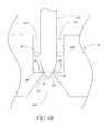
- FIG. 6Bis a schematic illustration of a vacuum cavity of the system of FIG. 6A having features in accordance with certain preferred embodiments of the present invention
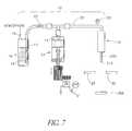
- FIG. 7is a simplified schematic illustration of a microfluidic aspirate-dispense system/apparatus for aspirating and dispensing precise quantities of liquid;
- FIG. 8is a schematic illustration of a one-dimensional array of dispensers
- FIG. 9is a schematic illustration of a two-dimensional array of dispensers
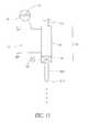
- FIG. 10is a cross-sectional detail view of the syringe pump of FIG. 7 ;
- FIG. 11is a schematic illustration of a solenoid valve dispenser for use in the system of FIG. 7 ;
- FIG. 12is a schematic graph (not to scale) of system pressure versus time illustrating a pressure pre-conditioned aspirate-dispense cycle.
- FIG. 13is a schematic illustration of an aspirate function in accordance with one preferred embodiment of the present invention.
- FIG. 1is a schematic cross-section view of a capillary tip, tube or pin 200 having features in accordance with one preferred embodiment of the present invention.
- the tip 200provides for improved microfluidic transfer of liquids for applications such as genomic microarraying and high throughput screening (HTS).
- HTShigh throughput screening
- the tip 200is used as a capillary or “gravity” pin to draw or collect source fluid and “spot,” deposit or contact dispense the fluid onto the target via physical contact (touch-off).
- the tip 200is used in conjunction with an aspirate-dispense system to actively aspirate source fluid and deposit the fluid via a contact or non-contact approach.
- the tip 200is generally cylindrical in shape and comprises a non-tapered upper portion or shank 202 with an upper end 203 , a tapered lower portion/outer surface 204 with a lower end 205 and an inner lumen or through cavity 206 .
- the inner lumen 206is generally cylindrical in shape with a top opening 208 , a non-tapered upper portion 210 , and a tapered lower portion/inner surface 212 to form a nozzle 214 having an orifice or opening 216 .
- the lower end 205 of the outer taper 204generally determines the spot or dot size.
- the outer taper 204leads to less accumulation of fluid on the tip outer surface.
- the inner taper 212is a desirable shape for capillary action, and reduces fluid mixing during aspiration and reduces the precipitation of gaseous bubbles within the fluid during aspirate-dispense operations.
- the tip 200further includes a generally circumferential groove, slot or notch 218 on the non-tapered upper portion 202 .
- the slot 218is generally V-shaped.
- the notch 218advantageously provides an easy break point in the case of accidental hard or jarring contact between the tip 200 and a contacting surface of the fluid target or source.
- the tip 200is fabricated from a ceramic material, and more preferably, from alumina.
- the ceramic materialprovides chemical inertness since alumina is inert to most chemical solvents.
- the ceramic materialprovides robustness, and hence can withstand extreme mechanical stress.
- the tip 200can be fabricated from a wide variety of materials with efficacy such as metals, alloys, and plastics, as required or desired, giving due consideration to the goals of providing chemical inertness and robustness.
- the outer surface 219 of the tip 200is coated with a thin film or coating 220 that is not only chemically inert and mechanically robust but is also hydrophobic to most fluids such as aqueous reagents, DMSO, and other common solvents.
- the film 220helps in keeping the tip 200 dry and also improves the microfluidic transfer.
- the film 220comprises a wear-resistant material so that it has an enhanced lifetime.
- Suitable coatings 220are silicon nitride, silicon carbide, titanium nitride, among others.
- the coating 220can be applied by a variety of methods such as plasma deposition and sputtering, among others, as is known in the art.
- a suitable hydrophobic coatingmay also be applied to the inner surface 221 of the tip 200 .
- the tip 200may be dimensioned in a wide variety of manners with efficacy, as required or desired, giving due consideration to the goals of providing reliable and repeatable microfluidic transfer of fluid.
- the tip 200has a length of 16 mm and an internal volume of about 20 microliters ( ⁇ L).
- the inner diameter at the nozzle end of the tip 200is in the range from about 20 to 180 microns ( ⁇ m) and the outer diameter is in the range from about 50 to 400 ⁇ m or more.
- the inner diameter at the nozzle end of the tip 200is in the range from about 100 to 300 ⁇ m and the outer diameter is in the range from about 400 to 900 ⁇ m.
- the tip 200( FIG. 1 ) is used as a capillary tip or gravity pin.
- the nozzle 214 of the tip 200is dipped in a source of fluid or reagent with the top opening 208 vented to atmospheric pressure.
- Capillary actioncauses a small volume of fluid to enter the inner lumen 206 through the nozzle orifice 216 .
- the nozzle end 205is touched to a target surface to transfer the reagent.
- multiple touch-offscan also be performed at the same or different site to transfer the desired quantity/volume of reagent to the desired target(s) or location(s).
- a robot arm and/or movable X, X-Y or X-Y-Z platformscan be utilized to provide relative motion between the tip 200 , and the target and source.
- the targetis typically a glass slide, substrate or membrane, among others.
- the touch-off or contact transferleaves a spot, dot or imprint of the fluid on the target.
- the spottypically has a size approximately the same as the outer diameter of the nozzle end 205 .
- the reagentis typically transferred to a microwell of a microtiter plate.
- microfluidic quantities of reagentscan be accurately and reliably collected and deposited with good reproducibility utilizing the capillary tip 200 as a microfluidic collection and deposition means.
- the inner taper 212 at the tip nozzle 214results in reduced local pressure drops during collection and deposition of fluid.
- thisprevents precipitation of unwanted gaseous bubbles from any gas that may be dissolved in the fluid.
- the tip through cavity 206advantageously, permits rapid and thorough cleaning of the tip 200 by allowing fluid to be forced through the lumen 206 , for example, by using a positive displacement pump. Also, desirably, any remaining source fluid within the tip 200 can be transferred back to the source by using a positive displacement pump in communication with the tip 200 . This reduces wastage of valuable source fluid.
- FIG. 3is a schematic representation of a random access tip/pin array or print head 230 for transferring microfluidic quantities of fluid or reagent.
- the print head (or random access micro-fluidic contact-transfer dispensing system) 230generally comprises an array 232 of floating contact transfer tips 200 ( FIG. 1 ) having respective base members 234 mounted on a tip holder, mount or sleeve 236 and a plurality of solenoid actuators 238 .
- the solenoids 238are mounted in a housing 240 and are positioned above respective tips 200 .
- the tip base 234is preferably fabricated from a magnetic material, such as a 400 series stainless steel, among other materials.
- the print head 230can be selectively operated to randomly access and deposit from the source 29 to the target 30 and can form a printed array that is a direct map of the reagent locations in the source plate 29 , for example, a microtiter plate with a plurality of microwells.
- the random access print head 230can also utilize a wide variety of other pins, tips, and the like for microfluidic transfer.
- the print head 230can utilize conventional pins that are thin rods of stainless steel with a sharpened fine point to provide a small spot size.
- the print head 230can also utilize conventional slotted pins.
- Other suitable pins, tips and the likecan be used with efficacy, as required or desired, giving due consideration to the goal of providing random collection and/or deposition of microfluidic quantities of fluids.
- the floating tip mount 236( FIGS. 3 and 4 ) is an air bearing mount with a plurality of holes 244 .
- the holes 244are machined to a close tolerance to slidingly accommodate the tips 200 while maintaining the alignment of the tips 200 .
- the mount 236is fabricated from brass with a low friction finish.
- the mount 236can be fabricated from a wide variety of materials such as other metals, alloys, ceramics, plastics with efficacy, as required or desired, giving due consideration to the goals of floatingly accommodating the tips 200 and maintaining a high tolerance alignment of the tips 200 .
- the tip base member 234( FIG. 3 ) has a hole 246 so that the top end 203 ( FIG. 1 ) of the tip 200 can reside in the hole 246 with the top opening 208 ( FIG. 1 ) vented to the atmosphere.
- the base members 234can be removably attached to the respective tips 200 so that selected tips 200 can be replaced, if required or desired. This allows differently configured and/or dimensioned tips 200 to be used with the print head 230 , and hence adds to the versatility of the invention.
- the bases 234also prevent the respective tips 200 to fall through the air bearing mount holes 244 ( FIG. 4 ).
- the solenoids 238can be a wide variety of commercially available solenoids and are controlled independently of one another.
- the solenoids 238When the solenoids 238 are energized, for example, the solenoid labeled 238 ′ in FIG. 3 , the respective tips 200 are raised as the respective bases 234 are attracted to the respective energized solenoids 238 .
- the solenoids 238When the solenoids 238 are not energized, for example, the solenoid labeled 238 ′′ in FIG. 3 , the respective tips 200 are lowered and the respective base members 234 are seated on the mount 236 . In the lowered position the tip(s) 200 can then be used for microfluidic transfer of reagent.
- the spacing between the tips 200generally corresponds to the spacing between the wells of the source plate 29 which is typically about 2.5 mm, 4.5 mm or 9 mm.
- the tips 200can be spaced alternatively depending on the particular use.
- the tips 200are arranged in a line or one-dimensional array 232 as schematically shown in FIG. 3 .
- the tips 200are arranged in a two-dimensional array 250 .
- the tips 200can be arranged in a wide variety of manners as dictated by the particular application.
- the number of tips 200 used in the arraycan vary from 1 to 384 or greater.
- Rectangular arrayscomprising [(4 ⁇ 2 x ) ⁇ (6 ⁇ 2 x )] tips 200 are also convenient to provide 96, 384, 1536, and so on, number of tips 200 .
- Square arrays of 2 xcan also be used, such as 2, 4, 8, 16, 32, and so on.
- the random access pin array 230is moved via a robot arm 252 .
- X, X-Y or X-Y-Z platforms 254can be utilized to move the source 29 and target 30 .
- a suitable controllercan be employed to monitor and control the operation of the various components of the print head 230 , such as the solenoids 238 , the robot arm 252 and the platforms 254 .
- a wash station 256( FIG. 3 ) is provided in combination or conjunction with the random access tip array 230 to maintain a dry tip.
- the wash station 256generally comprises a vacuum dry system 79 ( FIGS. 3 and 6A ) to remove any excess fluid that may have adhered to the outer surface of the tip 200 during dipping of the tips 200 in the source reagent or due to any moisture build-up on the outer surface of the tip 200 , for example, due to condensation from the air environment.
- the system 79( FIG. 6A ) generally includes a pump 80 connected to one or more vacuum cavities, apertures or orifices 82 . The tips 200 are inserted into the vacuum apertures 82 .
- the pump 80is activated for a predetermined amount of time and provides enough suction to remove or suck any excess fluid sticking to the outer surface of the tip 200 .
- the pump suctioncan also be adjusted so that it can remove excess fluid without disturbing any reagent, if present, inside the tip 200 .
- the vacuum drycan also be performed after washing the tips 200 in a cleaning fluid, for example, distilled water, among others.
- the tips 200can be dipped in a volatile solvent such as isopropyl alcohol, among others, to maintain a dry tip.
- the hydrophobic coating 220 ( FIG. 2 ) and the outer taper 204 ( FIG. 1 ) to a small nozzle end 205 ( FIG. 1 )further assist in keeping the tips 200 dry and free of excess liquid.
- the tips 200may also be dried by blotting them on an absorbent material.
- the wash station 256( FIG. 3 ) generally comprises a wash/cleaning bath 258 , an ultrasonic bath 260 and the vacuum system 79 ( FIG. 6A ) for cleaning the tips 200 .
- the tips 200are dipped in the wash bath 258 and draw wash/cleaning fluid by capillary action. This dilutes any remaining reagent in the tips 200 .
- the tips 200are then inserted in the vacuum cavities 82 ( FIG. 6A ) of the vacuum system 79 and the pump 80 is operated to provide enough suction to remove some or all of the fluid from the tips 200 .
- the tips 200can also be spotted in a waste or other suitable position to remove some or all of the fluid within the tips 200 .
- the vacuum system 79 and the spotting processcan be used in combination to remove the fluid from the tips 200 .
- the wash bath cleaning followed by the fluid removal from the tipscan be repeated a number of times, as required or desired. Typically two or three cleanses in the wash bath 258 are sufficient.
- the tips 200are then further cleaned by dipping in the ultrasonic bath 260 . This is followed by a vacuum dry of the tips 200 using the vacuum dry system 79 ( FIG. 6A ).
- the tips 200may also be cleaned by blotting them on an absorbent material.
- the vacuum cavities or holes 82 of the vacuum dry system 79comprise an upper cavity or hole 82 a and a lower cavity or hole 82 b .
- the upper cavity 82 a and the lower cavity 82 bare in fluid communication with one another through an opening 84 and are separated by a step or shoulder 86 .
- the upper cavity 82 ais sized and configured to accommodate the girth of the non-tapered upper portion or shank 202 of the tip 200 .
- the opening 84 and step 86are sized and configured to engage the tapered lower portion 204 of the tip 200 .
- the step 86forms a seal or a partial seal with the tip tapered portion 204 when the tip tapered portion 204 engages, contacts or abuts the step 86 .
- thisfacilitates in the clearing or removal of fluid from inside the tip 200 .
- the step 86can be substantially rigid in nature or it can comprise a resilient or flexible material, as required or desired, giving due consideration to the goals of forming a seal or partial seal and/or facilitating the cleaning of the tip 200 .
- an O-ring or washer 88( FIG. 6B ) is utilized to from a seal or partial seal with the tip tapered portion 204 .
- the O-ring 88can be substantially rigid in nature or it can comprise a resilient or flexible material, as required or desired, giving due consideration to the goals of forming a seal or partial seal and/or facilitating the cleaning of the tip 200 .
- the O-ring 88can be provided on a suitable surface or wall of the vacuum cavity 82 , as required or desired, giving due consideration to the goals of providing a seal or partial seal and/or facilitating the cleaning of the tip 200 .
- the O-ring 88can be seated on the step 86 , mounted on a side wall 90 or 92 of the cavity 82 and/or can replace the step 86 .
- an O-ring or washer 88 ′( FIG. 6B ) is utilized to from a seal or partial seal with the tip non-tapered portion or shank 202 .
- the O-ring 88 ′can be substantially rigid in nature or it can comprise a resilient or flexible material, as required or desired, giving due consideration to the goals of forming a seal or partial seal and/or facilitating the cleaning of the tip 200 .
- the O-ring 88 ′can be provided on a suitable surface or wall of the vacuum cavity 82 , for example, the side wall 90 , as required or desired, giving due consideration to the goal of providing a seal or partial seal and/or facilitating the cleaning of the tip 200 .
- the O-ring 88 ′can be used independently of or in combination with one or both of the step 86 and O-ring 88 , as required or desired, giving due consideration to the goal of providing a seal or partial seal and/or facilitating the cleaning of the tip 200 .
- the vacuum dry system 79facilitates in the removal or cleaning of fluid from the outer surface of the tip 200 .
- the vacuum dry system 79facilitates in the removal or clearing of fluid from inside the tip 200 .
- thisallows for improved cleaning of the tip 200 , and hence enhanced performance.
- all the tips 200are raised by energizing the solenoids 238 .
- the print head 230is positioned and aligned over the source 29 by utilizing the robot arm 252 and/or the movable platforms 254 .
- a first tip 200is lowered by de-energizing or turning off the corresponding solenoid 238 .
- the first tip 200dips into a microwell of the source plate 29 to draw fluid by capillary action.
- the first tip 200is raised by energizing the corresponding solenoid 238 .
- Relative motionis provided between the source plate 29 and the print head 230 , by the robot arm 252 and/or the movable platform 254 , to align a second tip 200 with a corresponding microwell of the source plate 29 .
- the second tip 200is lowered and collects source fluid from the microwell.
- the second tip 200is then raised.
- Subsequent tips 200are lowered and raised in a similar manner. This random access collection process is continued until all the tips 200 are loaded with the sample fluid.
- the print head 230is then positioned and aligned over the target 30 by the robot arm 252 and/or the movable platforms 254 .
- a first tip 200is lowered by de-energizing or turning off the corresponding solenoid 238 and contacts the target 30 to transfer source fluid.
- the first tip 200is raised by energizing the corresponding solenoid 238 .
- Relative motionis provided between the target 30 and the print head 230 , by the robot arm 252 and/or the movable platform 254 , to align a second tip 200 over the target 30 .
- the second tip 200is lowered and contacts the target 30 to deposit fluid.
- the second tip 200is then raised. Subsequent tips 200 are lowered and raised in a similar manner. This random access deposition process is continued until all the tips 200 have deposited the fluid samples from the source plate 29 onto the target 30 .
- the random access print head 230( FIG. 3 ) can be operated in several modes. These modes include a combination of both random access collection and deposition, random access collection only, and random access deposition only.
- the random access collection and deposition modeutilizes the random access collection process followed by the random access deposition process, as described above.
- source fluidsare collected, as described above for the random access collection process.
- the source fluidsare then deposited by simultaneously lowering all the tips 200 over the target 30 .
- more than one but less than all of the tips 200may be lowered or raised to simultaneously collect or deposit fluid.
- all the tips 200are dipped simultaneously into the source plate 29 to collect source fluids.
- the source fluidsare then deposited, as described above for the random access deposition process.
- more than one but less than all of the tips 200may be lowered or raised to simultaneously collect or deposit fluid.
- the tip 200can hold a sufficient volume of fluid that allows multiple touch-offs at the same position on the target 30 .
- the same reagentmay be deposited on different targets 30 after a single dip of the tip 200 . This further adds to the versatility of the random access print head 230 .
- the target 30is generally a glass slide, substrate or membrane, among others, and the tips 200 form dots or spots of the source fluids on the target 30 .
- the tips 200can form dots having a diameter in the range from about 50 ⁇ m to greater than about 400 ⁇ m and can form arrays having densities in the range from less than about 10 dots/cm 2 to greater than about 6000 dots/cm 2 .
- the size of these spots or dotsis generally determined by the outer diameter of the nozzle end 205 of the tip 200 .
- the tips 200can also transfer fluid volumes as low as in the picoliter range and up to about 100 nanoliter (nL) or more.
- the target 30is typically a microtiter plate, such as a 96, 384 or 1536 well plate.
- the tips 200can transfer fluid volumes in the range from about 1 nL to about 200 nL or more.
- the print head 230 of the present inventioncan randomly collect and randomly deposit microfluidic quantities of fluid.
- the print head 230can also be programmed to create a direct map of the source fluids from the source 29 on the target 30 or to create any desired pattern or print on the target 30 .
- the floating tips 200FIG. 3
- the floating tips 200can compensate for any small deviations in flatness on the surface of the source 29 or target 30 , since the tips are movably held in the print head 230 . This can reduce damage to the tips 200 and other components of the print head 230 in case of possible misalignment with the source 29 and/or target 30 .
- one or more optical sensorsmay be used to monitor the alignment and positioning of the tips 200 relative to the source 29 and target 30 .
- FIG. 7is a schematic drawing of a microfluidic aspirate-dispense apparatus or system 10 having features in accordance with one preferred embodiment.
- the aspirate-dispense system 10generally comprises a dispenser 12 with the tip 200 ( FIGS. 1 and 7 ) and a positive displacement syringe pump 22 intermediate a reservoir 16 .
- the dispenser 12is used to aspirate a predetermined quantity of fluid or reagent from a source or receptacle 29 and dispense a predetermined quantity, in the form of droplets or a spray pattern, of the source fluid onto or into a target 30 .
- the source 29is typically a microtiter plate
- the target 30is typically a glass slide, substrate or membrane for genomic microarraying and a microtiter plate for compound reformatting.
- the positive displacement pump 22meters the volume and/or flow rate of the reagent aspirated and, more critically, of the reagent dispensed.
- the reservoir 16contains a wash or system fluid 14 , such as distilled water, which fills most of the aspirate-dispense system 10 .
- One or more robot armsmay be used to maneuver the aspirate-dispense system 10 or alternatively the aspirate-dispense system 10 and/or its associated components may be mounted on movable X, X-Y or X-Y-Z platforms.
- the robot arms and the movable platformsmay also be used in combination.
- the reservoir 16 and syringe pump 22can be filled with the reagent and the system 10 can be used purely for dispensing.
- multiple aspirate-dispense systems 10may be utilized to form a line/one-dimensional array of dispensers 12 ( FIG. 8 ) or a two-dimensional array of dispensers 12 ( FIG. 9 ).
- the pump 22is preferably a high-resolution, positive displacement syringe pump hydraulically coupled to the dispenser 12 .
- pump 22may be any one of several varieties of commercially available pumping devices for metering precise quantities of liquid.
- a syringe-type pump 22as shown in FIG. 7 , is preferred because of its convenience and commercial availability.
- a wide variety of other direct current fluid source meansmay be used, however, to achieve the benefits and advantages as disclosed herein. These may include, without limitation, rotary pumps, peristaltic pumps, squash-plate pumps, and the like, or an electronically regulated fluid current source.
- the syringe pump 22generally comprises a syringe housing 62 of a predetermined volume and a plunger 64 which is sealed against the syringe housing by O-rings or the like.
- the plunger 64mechanically engages a plunger shaft 66 having a lead screw portion 68 adapted to thread in and out of a base support (not shown).
- a base supportnot shown.
- Any number of suitable motors or mechanical actuatorsmay be used to drive the lead screw 68 .
- a stepper motor 26FIG. 7
- other incremental or continuous actuator deviceis used so that the amount and/or flow rate of fluid or reagent can be precisely regulated.
- the syringe pump 22is connected to the reservoir 16 and the dispenser 12 using tubing 23 provided with luer-type fittings for connection to the syringe and dispenser.
- Various shut-off valves 25 and check valvesmay also be used, as desired or needed, to direct the flow of fluid 14 to and/or from the reservoir 16 , syringe pump 22 and dispenser 12 .
- the solenoid valve dispenser 12generally comprises a solenoid-actuated drop-on-demand valve 20 , including a valve portion 34 and a solenoid actuator 32 , hydraulically coupled to the tube or tip 200 of the present invention.
- the nozzle 214 of the tip 200serves as the aspirating and dispensing nozzle.
- the solenoid valve 20is energized by one or more electrical pulses 13 provided by a pulse generator 19 to open and close the valve 20 at a predetermined frequency and/or duty cycle.
- a detailed description of one typical solenoid-actuated valvecan be found in U.S. Pat. No.
- the tip ( FIGS. 1 and 7 ) of the present inventionmay also be used in conjunction with a number of other dispensers well known in the art for dispensing a liquid, such as a piezoelectric dispenser, a fluid impulse dispenser, a heat actuated dispenser or the like.
- the wash fluid reservoir 16may be any one of a number of suitable receptacles capable of allowing the wash fluid 14 , such as distilled water, to be siphoned into pump 22 .
- the reservoirmay be pressurized, as desired, but is preferably vented to the atmosphere, as shown, via a vent opening 15 .
- the particular size and shape of the reservoir 16is relatively unimportant.
- a siphon tube 17extends downward into the reservoir 16 to a desired depth sufficient to allow siphoning of wash fluid 14 .
- the siphon tube 17extends as deep as possible into the reservoir 16 without causing blockage of the lower inlet portion of the tube 17 .
- the lower inlet portion of the tube 17may be cut at an angle or have other features as necessary or desirable to provide consistent and reliable siphoning of wash fluid 14 .
- the hydraulic coupling between the pump 22 and the dispenser 12provides for the situation where the input from the pump 22 exactly equals the output from the dispenser 12 under steady state conditions. Therefore, the positive displacement system uniquely determines the output volume of the system while the operational dynamics of the dispenser 12 serve to transform the output volume into ejected drop(s) having size, frequency and velocity.
- Providing a positive displacement pump 22 in series with a dispenser 12has the benefit of forcing the dispenser 12 to admit and eject a quantity and/or flow rate of reagent as determined solely by the positive displacement pump 22 for steady state operation.
- the syringe pump 22acts as a forcing function for the entire system, ensuring that the desired flow rate is maintained regardless of the duty cycle, frequency or other operating parameters of the dispensing valve, such as the solenoid-actuated valve 20 ( FIG. 11 ).
- the solenoid-actuated valve 20FIG. 11
- the transitions between various modes (aspirate, dispense, purge/wash) and/or flow rates or other operating parameterscan result in pressure transients and/or undesirable latent pressure conditions within the aspirate-dispense system 10 ( FIG. 7 ).
- Purge and wash functionsusually entail active dispensing in a non-target position. In some cases, when the same reagent is to be aspirated again, several aspirate-dispense cycles can be performed before executing a purge or wash function. Also, sometimes a purge function may have to be performed during a dispense function, for example, to alleviate clogging due to the precipitation of gaseous bubbles within the system and/or source fluid.
- a pressure pre-conditioning methodcauses a steady state pressure to exist within a liquid delivery system, such as the positive-displacement aspirate-dispense system 10 ( FIG. 7 ), prior to initiating dispensing operations.
- the initial positive pressureovercomes the system's elastic compliance and thereby achieves a steady state pressure condition prior to dispensing.
- thisassures that the fluid displaced by the syringe pump 22 ( FIG. 7 ) will be completely transferred as output to the system nozzle, such as the nozzle 214 ( FIGS. 1 and 7 ).
- One preferred pressure pre-conditioning methodfacilitates the aspirate-dispense process by providing an efficient pressure compensation scheme which is efficient in both fluid or reagent consumption and time.
- an efficient pressure compensation schemewhich is efficient in both fluid or reagent consumption and time.
- FIG. 12shows a schematic graph (not to scale) illustrating the pressure-time history for a pressure compensated aspirate-dispense cycle in accordance with one preferred pressure pre-conditioning/compensation method of the invention.
- the x-axis 120represents the time and the y-axis 122 represents the system pressure.
- Line 124depicts the predetermined and/or steady state pressure during which dispensing occurs
- line 126depicts the pressure compensation prior to the aspirate function
- line 128depicts the pressure during the aspirate function
- line 130depicts the pressure compensation prior to the dispense function.
- a system pressure close to or below zerois preferred. Referring to FIG. 12 , this is achieved by first “venting” the system (line 126 ) to release the pressure. This may be done in a variety of ways, such as performing a series of rapid waste dispenses.
- the nozzle 214FIGS. 1 and 7
- the drop-on-demand valve 20FIG. 11
- the opening of the valve 20causes some system fluid 14 ( FIG. 12
- valve 20may remain closed while the syringe pump 22 ( FIG. 7 ) is operated in the reverse direction, as required to release system pressure.
- the residual pressuremay also be released by providing a separate relief valve (not shown) for the syringe pump 22 ( FIG. 7 ) or the shut-off valve 25 ( FIG. 7 ) can be opened to release system fluid 14 ( FIG. 7 ) back into the reservoir 16 ( FIG. 7 ).
- the source fluid from the source 29can be aspirated (line 128 ) without the spurious dispense or ejection of system fluid 14 ( FIG. 7 ) and/or residual aspirated fluid into the source 29 ( FIG. 7 ).
- the nozzle 214FIGS. 7 and 11
- the valve 20FIG. 11
- the syringe pump 22FIG. 7
- the reverse directioncreating a reduced or negative pressure (line 128 ), to aspirate source fluid or reagent into the tip 200 ( FIG. 7 ) of the aspirate-dispense system 10 ( FIG. 7 ).
- the valve 20( FIG. 11 ) is open continuously during aspiration, that is, a 100% duty cycle is utilized.
- the system pressureis at or close to zero, predetermined small volumes of source fluid can be substantially accurately aspirated by metering the displacement of the syringe pump 22 ( FIG. 7 ).
- the reduced/negative aspirate system pressureis kept close to zero so that the flow of source fluid into the tip 200 and nozzle 214 ( FIG. 7 ) is maintained generally laminar.
- the displacement rate of the syringe pump plunger 64( FIG.
- utilizing a 100% valve duty cycleduring aspiration, further assists in maintaining a generally laminar flow of source fluid into the nozzle 214 and tip 200 .
- turbulent mixing of source fluid with system fluid 14( FIG. 7 ) is reduced, and any dilution of the source fluid will essentially be due to diffusion.
- the diffusion processis very slow, and hence the overall effective dilution of the source fluid or reagent is small or negligible.
- the aspiration processresults in a partial vacuum or residual reduced/negative pressure within the aspirate-dispense 10 ( FIG. 7 ), which is less than the preferred dispense steady state pressure (line 124 ).
- the system pressureis preferably raised from the reduced or negative value to a positive dispense steady state and/or predetermined value.
- a simple, fast technique to raise the system pressure to the preferred dispense pressureis by displacing the syringe pump plunger 64 ( FIG. 10 ) in the forward direction while keeping the drop-on-demand valve 20 ( FIG. 11 ) in the closed position. This preferred “pressurizing” pressure compensation is illustrated by line 130 ( FIG. 12 ).
- the predetermined quantity or quantities of aspirated source fluidcan be accurately dispensed.
- the displacement of the syringe pump plunger 64can be synchronized with the duty cycle of the drop-on-demand valve 20 ( FIG. 11 ) or, alternatively, the pump 22 ( FIG. 7 ) can be used to supply a generally continuous flow rate.
- a pressurization schemeis efficient, does not waste reagent and reduces reagent dilution.
- the above pressurization schemecan also be followed by a pre-dispense operation for fine tuning of the system pressure to the desired steady state and/or predetermined value.
- This pre-dispensetypically involves dispensing a small quantity of fluid back into the aspiration fluid source.
- the pre-dispensemay also be performed by dispensing in a waste position.
- the system pressureis sufficiently close to the steady-state and/or predetermined value, and hence this pre-dispensing of fluid results in small, negligible or no wastage of fluid.
- the pressure compensation methods discussed hereinmay be employed whenever transient pressure variations occur in the aspirate and/or dispense hydraulic system, giving due consideration to achieving the goal of providing predetermined and/or steady state pressures. These pressure transients may occur due to hydraulic “capacitance effect”, leakage or the precipitation of small gaseous bubbles, or during initial start-up or intermittent dispensing operations.
- the importance of performing aspirate and dispense functions at the optimal pressureshas been illuminated so far.
- the amount of pre-pressurization needed to achieve steady state operationmay be determined empirically for a given set-up.
- An experimental parametric analysismay be performed for a given set-up and several correlations can be obtained.
- This open-loop control techniquewill assist in determining the actuations of the syringe pump 22 ( FIG. 7 ) to achieve the optimal operating pressure.
- one or more pressure sensors 50may be included to monitor the system pressure.
- the pressure measurements as provided by one or more pressure sensors 50can also be used to provide diagnostic information about various fluid and flow parameters of the hydraulic system.
- the pressure sensors 50can be placed at the drop-on-demand valve 20 ( FIG. 11 ) and/or at appropriate positions intermediate the syringe pump 22 ( FIG. 7 ) and the dispenser 12 ( FIG. 7 ), such as on the feedline 23 , as illustrated in FIG. 7 .
- the pressure sensors 50may also be placed at other suitable locations, as required or desired, giving due consideration to the goals of providing pressure compensation and reliable aspiration and dispensing.
- Suitable pressure sensors 50are well known by those of ordinary skill in the art and, accordingly, are not described in greater detail herein.
- the semi-empirical approachutilizes fluid flow theory and measurements from one or more pressure sensors 50 positioned at suitable locations.
- the apparatus or system 10may be used for a wide variety of microfluidic applications such as printing of micro-arrays and high throughput screening, among others.
- the operation of the aspirate-dispense system 10( FIG. 1 ) may be monitored and controlled by a suitable automated control system. Additionally, the control system may be interfaced with any robot arms and/or X, X-Y or X-Y-Z movable platforms used in conjunction with the aspirate-dispense system 10 , source 29 , target 30 and waste receptacle to facilitate maneuverability of the various components of the system and its associated elements.
- the system 10( FIG. 7 ) can also be used for contact deposition of source fluid onto the target 30 .
- a dropcan be formed at the nozzle end 205 by incrementing the syringe pump 22 ( FIG. 7 ). The drop can then be applied to the target 30 . Multiple touch-offs can also be performed, as required or desired.
- the system 10can also be operated without the dispenser 12 .
- the syringe pump 22is operated in the reverse direction to aspirate fluid.
- the source fluidcan then be transferred to the target 30 by non-contact dispensing or contact deposition.
- the tip 200( FIGS. 1 and 7 ) provides several benefits and advantages in conjunction with the aspirate-dispense system 10 ( FIG. 7 ).
- the tip outer taper 204 and the small outer diameter at the nozzle end 205leads to less accumulation of fluid on the outer surface of the tip 200 and this improves the reliability, repeatability and accuracy of the system 10 .
- a wash station 268( FIG. 7 ) with a vacuum dry system 79 ( FIGS. 6A-6B ) is provided with the system 10 ( FIG. 7 ) to maintain a dry tip.
- the vacuum dry system 79is used to remove any remove any excess fluid that may have adhered to the outer surface of the tip 200 ( FIGS.
- the vacuum drycan also be performed after washing the tip 200 ( FIGS. 1 and 7 ) in a cleaning fluid, for example, distilled water, among others.
- a cleaning fluidfor example, distilled water, among others.
- the tip 200can be dipped in a volatile solvent such as isopropyl alcohol, among others, to maintain a dry tip.
- the hydrophobic coating 220 ( FIG. 2 ) and the outer taper 204 ( FIG. 1 ) to a small nozzle end 205 ( FIG. 1 )further assist in keeping the tip 200 dry and free of excess liquid. This further improves the repeatability and accuracy of the aspirate-dispense system 10 ( FIG. 7 ).
- the inner taper 212 ( FIG. 1 ) of the tip 200also improves the performance of the system 10 ( FIG. 7 ) in terms of less precipitation of gaseous bubbles within the source reagent and/or the system fluid 14 . This is because the inner taper 212 results in smaller local pressure drops during dispensing and aspiration.
- the inner taper 212also reduces the mixing of source reagent with the system fluid 14 by further improving the generally laminar flow during aspiration. Advantageously, this reduces the wastage of valuable reagent.
- the syringe pump 22prior to aspiration of source fluid the syringe pump 22 ( FIG. 7 ) is operated in the reverse direction with the nozzle orifice 216 ( FIG. 1 ) exposed to the atmosphere to draw a small quantity of air into the tip 200 . Referring to FIG. 13 , this forms a small air bubble 262 within the system fluid 14 in the tip 200 .
- the volume of the bubble 262can be in the range from less than about 0.5 ⁇ L to greater than about 1.0 ⁇ L.
- the tip 200is then dipped in the source fluid and the syringe pump 22 is decremented to aspirate source fluid 264 ( FIG. 13 ) into the tip 200 .
- the bubble 262causes the aspirated fluid laminar velocity profile 266 to have a generally blunt shape by reducing the fluid drag imposed on the aspirated fluid 264 near the tip inner surface or wall 221 .
- thisreduces the area of the interface between the system fluid 14 and the aspirated source fluid 264 , and hence desirably reduces the mixing and dilution of the aspirated fluid 264 with the system fluid 14 .
- the target 30is generally a glass slide, substrate or membrane, among others, and the system 10 ( FIG. 7 ) is used to form dots or spots of the source fluids on the target 30 .
- the system 10can form dots having a diameter in the range from about 50 ⁇ m to greater than about 400 ⁇ m and can form arrays having densities in the range from less than about 10 dots/cm 2 to greater than about 6000 dots/cm 2 .
- the size of these spots or dotsis generally determined by the outer diameter of the nozzle end 205 of the tip 200 .
- the system 10can also transfer fluid volumes as low as in the picoliter range and up to about 100 nanoliter (nL) or more.
- the target 30is typically a microtiter plate, such as a 96, 384 or 1536 well plate.
- the system 10can transfer fluid volumes in the range from about 1 nL to about 200 nL or more.
Landscapes
- Chemical & Material Sciences (AREA)
- Health & Medical Sciences (AREA)
- Chemical Kinetics & Catalysis (AREA)
- Physics & Mathematics (AREA)
- Organic Chemistry (AREA)
- Clinical Laboratory Science (AREA)
- Life Sciences & Earth Sciences (AREA)
- Analytical Chemistry (AREA)
- Biochemistry (AREA)
- General Health & Medical Sciences (AREA)
- General Physics & Mathematics (AREA)
- Immunology (AREA)
- Pathology (AREA)
- Fluid Mechanics (AREA)
- Automatic Analysis And Handling Materials Therefor (AREA)
Abstract
Description
Claims (27)
Priority Applications (1)
| Application Number | Priority Date | Filing Date | Title |
|---|---|---|---|
| US10/421,636US7736591B2 (en) | 1998-07-07 | 2003-04-22 | Method and apparatus for liquid dispensing |
Applications Claiming Priority (8)
| Application Number | Priority Date | Filing Date | Title |
|---|---|---|---|
| US9192898P | 1998-07-07 | 1998-07-07 | |
| US10671998P | 1998-11-02 | 1998-11-02 | |
| US11306298P | 1998-12-21 | 1998-12-21 | |
| US13846499P | 1999-06-10 | 1999-06-10 | |
| US13902499P | 1999-06-14 | 1999-06-14 | |
| US34878799A | 1999-07-07 | 1999-07-07 | |
| US09/459,245US6551557B1 (en) | 1998-07-07 | 1999-12-10 | Tip design and random access array for microfluidic transfer |
| US10/421,636US7736591B2 (en) | 1998-07-07 | 2003-04-22 | Method and apparatus for liquid dispensing |
Related Parent Applications (1)
| Application Number | Title | Priority Date | Filing Date |
|---|---|---|---|
| US09/459,245DivisionUS6551557B1 (en) | 1998-07-07 | 1999-12-10 | Tip design and random access array for microfluidic transfer |
Publications (2)
| Publication Number | Publication Date |
|---|---|
| US20040072365A1 US20040072365A1 (en) | 2004-04-15 |
| US7736591B2true US7736591B2 (en) | 2010-06-15 |
Family
ID=27557414
Family Applications (2)
| Application Number | Title | Priority Date | Filing Date |
|---|---|---|---|
| US09/459,245Expired - Fee RelatedUS6551557B1 (en) | 1998-07-07 | 1999-12-10 | Tip design and random access array for microfluidic transfer |
| US10/421,636Expired - LifetimeUS7736591B2 (en) | 1998-07-07 | 2003-04-22 | Method and apparatus for liquid dispensing |
Family Applications Before (1)
| Application Number | Title | Priority Date | Filing Date |
|---|---|---|---|
| US09/459,245Expired - Fee RelatedUS6551557B1 (en) | 1998-07-07 | 1999-12-10 | Tip design and random access array for microfluidic transfer |
Country Status (1)
| Country | Link |
|---|---|
| US (2) | US6551557B1 (en) |
Cited By (10)
| Publication number | Priority date | Publication date | Assignee | Title |
|---|---|---|---|---|
| US20080273064A1 (en)* | 2004-12-10 | 2008-11-06 | Canon Finetech Inc. | Ink-feeding device and pressure-generating method |
| US20090223012A1 (en)* | 2006-09-22 | 2009-09-10 | Fujifilm Corporation | Liquid suction device |
| US20110143393A1 (en)* | 2008-04-14 | 2011-06-16 | Hartmut Merz | Automatic device for carrying out detection reactions, and method for dosing reagents onto microscope slides |
| US20110171744A1 (en)* | 2008-07-02 | 2011-07-14 | Beckman Coulter Inc. | Dispensing device |
| WO2014088286A1 (en)* | 2012-12-04 | 2014-06-12 | Samyang Biopharmaceuticals Corporation | Apparatus and method for manufacturing micro-particles |
| CN104759373A (en)* | 2012-04-25 | 2015-07-08 | 艾博生物医药(杭州)有限公司 | Liquid distribution device |
| US9873133B2 (en) | 2014-06-13 | 2018-01-23 | Creating Nano Technologies, Inc. | Extrusion device and coating system |
| US11117289B2 (en) | 2017-06-06 | 2021-09-14 | Nantero, Inc. | Storage and delivery systems for colloidal dispersions |
| US11801506B2 (en) | 2018-01-30 | 2023-10-31 | Hewlett-Packard Development Company, L.P. | Fluid ejections in nanowells |
| US12000852B2 (en) | 2018-07-23 | 2024-06-04 | Scienion Gmbh | Apparatus and method for isolating single particles from a particle suspension |
Families Citing this family (105)
| Publication number | Priority date | Publication date | Assignee | Title |
|---|---|---|---|---|
| US7285422B1 (en) | 1997-01-23 | 2007-10-23 | Sequenom, Inc. | Systems and methods for preparing and analyzing low volume analyte array elements |
| US6465178B2 (en)* | 1997-09-30 | 2002-10-15 | Surmodics, Inc. | Target molecule attachment to surfaces |
| US6762019B2 (en)* | 1997-09-30 | 2004-07-13 | Surmodics, Inc. | Epoxide polymer surfaces |
| US20020159919A1 (en)* | 1998-01-09 | 2002-10-31 | Carl Churchill | Method and apparatus for high-speed microfluidic dispensing using text file control |
| US7470547B2 (en)* | 2003-07-31 | 2008-12-30 | Biodot, Inc. | Methods and systems for dispensing sub-microfluidic drops |
| US6428752B1 (en)* | 1998-05-14 | 2002-08-06 | Affymetrix, Inc. | Cleaning deposit devices that form microarrays and the like |
| US20030215957A1 (en)* | 1998-02-20 | 2003-11-20 | Tony Lemmo | Multi-channel dispensing system |
| US6866881B2 (en)* | 1999-02-19 | 2005-03-15 | Speedline Technologies, Inc. | Dispensing system and method |
| US7189365B1 (en)* | 1999-03-04 | 2007-03-13 | Riken | Liquid treating equipment including a storage vessel and a discharge vessel |
| GB9906477D0 (en)* | 1999-03-19 | 1999-05-12 | Pyrosequencing Ab | Liquid dispensing apparatus |
| EP1200841A1 (en)* | 1999-08-13 | 2002-05-02 | Cartesian Technologies, Inc. | Apparatus for liquid sample handling |
| US7160511B2 (en)* | 2000-02-18 | 2007-01-09 | Olympus Corporation | Liquid pipetting apparatus and micro array manufacturing apparatus |
| US6756232B1 (en)* | 2000-03-20 | 2004-06-29 | Perkinelmer Las, Inc. | Method and apparatus for producing compact microarrays |
| US6471917B1 (en)* | 2000-04-11 | 2002-10-29 | Affymax, Inc. | System and method for single or multiple bead distribution with an adjustable capillary |
| US6943035B1 (en)* | 2000-05-19 | 2005-09-13 | Genetix Limited | Liquid dispensing apparatus and method |
| US6902702B1 (en)* | 2000-08-16 | 2005-06-07 | University Health Network | Devices and methods for producing microarrays of biological samples |
| US20050106621A1 (en)* | 2000-08-16 | 2005-05-19 | Winegarden Neil A. | Devices and methods for producing microarrays of biological samples |
| CA2322086A1 (en)* | 2000-10-03 | 2001-01-30 | University Health Network | Methods for production of microarrays of biological samples |
| US7135146B2 (en)* | 2000-10-11 | 2006-11-14 | Innovadyne Technologies, Inc. | Universal non-contact dispense peripheral apparatus and method for a primary liquid handling device |
| US6852291B1 (en)* | 2000-10-11 | 2005-02-08 | Innovadyne Technologies, Inc. | Hybrid valve apparatus and method for fluid handling |
| EP1332000B1 (en) | 2000-10-30 | 2012-06-20 | Sequenom, Inc. | Method for delivery of submicroliter volumes onto a substrate |
| GB2377707B (en)* | 2001-04-26 | 2004-10-20 | Thk Co Ltd | Microarraying head and microarrayer |
| JP2004535572A (en)* | 2001-06-13 | 2004-11-25 | ケニス エフ. ウーヘンハイマー, | Automated fluid handling systems and methods |
| US7402286B2 (en)* | 2001-06-27 | 2008-07-22 | The Regents Of The University Of California | Capillary pins for high-efficiency microarray printing device |
| US6855538B2 (en)* | 2001-06-27 | 2005-02-15 | The Regents Of The University Of California | High-efficiency microarray printing device |
| US7297311B2 (en)* | 2001-06-29 | 2007-11-20 | Sysmex Corporation | Automatic smear preparing apparatus and automatic sample analysis system having the same |
| DE10136790A1 (en)* | 2001-07-27 | 2003-02-13 | Eppendorf Ag | Method for dosing liquids and device for carrying out the method |
| US20050019223A1 (en)* | 2001-08-10 | 2005-01-27 | Platt Albert Edward | Liquid delivery apparatus and method |
| WO2003013718A1 (en)* | 2001-08-10 | 2003-02-20 | Oxford Glycosciences (Uk) Ltd | Liquid delivery apparatus and method |
| US6579724B2 (en)* | 2001-09-13 | 2003-06-17 | First Ten Angstroms | Dispensing method and apparatus for dispensing very small quantities of fluid |
| US6759012B2 (en)* | 2001-11-05 | 2004-07-06 | Genetix Limited | Pin holder for a microarraying apparatus |
| US6913933B2 (en)* | 2001-12-03 | 2005-07-05 | Ortho-Clinical Diagnostics, Inc. | Fluid dispensing algorithm for a variable speed pump driven metering system |
| US6827905B2 (en)* | 2002-01-14 | 2004-12-07 | Becton, Dickinson And Company | Pin tool apparatus and method |
| US7169616B2 (en)* | 2002-01-25 | 2007-01-30 | Innovadyne Technologies, Inc. | Method of purging trapped gas from a system fluid contained in an actuation valve |
| US7288228B2 (en)* | 2002-02-12 | 2007-10-30 | Gilson, Inc. | Sample injection system |
| US20030208936A1 (en)* | 2002-05-09 | 2003-11-13 | Lee Charles Hee | Method for manufacturing embroidery decorated cards and envelopes |
| US20060088447A1 (en)* | 2002-05-28 | 2006-04-27 | Pss Bio Instruments | Specimen distributing device, coating part manufacturing method, specimen distributing method and substrate activating device |
| US6789965B2 (en)* | 2002-05-31 | 2004-09-14 | Agilent Technologies, Inc. | Dot printer with off-axis loading |
| US6997066B2 (en)* | 2002-08-07 | 2006-02-14 | Perkinelmer Las, Inc. | Dispensing apparatus |
| US20030166263A1 (en)* | 2002-12-30 | 2003-09-04 | Haushalter Robert C. | Microfabricated spotting apparatus for producing low cost microarrays |
| GB0302281D0 (en)* | 2003-01-31 | 2003-03-05 | Biorobotics Ltd | Liquid transfer system |
| WO2004091746A2 (en)* | 2003-04-08 | 2004-10-28 | Irm, Llc | Material removal and dispensing devices, systems, and methods |
| SG116492A1 (en)* | 2003-04-29 | 2005-11-28 | Nanyang Poly Technic | A method and apparatus for microarraying of biological fluids samples on biological substrates. |
| WO2004099059A2 (en)* | 2003-04-30 | 2004-11-18 | Aurora Discovery, Inc. | Method and system for precise dispensation of a liquid |
| US20060233671A1 (en)* | 2003-09-19 | 2006-10-19 | Beard Nigel P | High density plate filler |
| US9492820B2 (en) | 2003-09-19 | 2016-11-15 | Applied Biosystems, Llc | High density plate filler |
| US8277760B2 (en)* | 2003-09-19 | 2012-10-02 | Applied Biosystems, Llc | High density plate filler |
| US7998435B2 (en)* | 2003-09-19 | 2011-08-16 | Life Technologies Corporation | High density plate filler |
| US20050220675A1 (en)* | 2003-09-19 | 2005-10-06 | Reed Mark T | High density plate filler |
| US7695688B2 (en)* | 2003-09-19 | 2010-04-13 | Applied Biosystems, Llc | High density plate filler |
| US20050226782A1 (en)* | 2003-09-19 | 2005-10-13 | Reed Mark T | High density plate filler |
| US7407630B2 (en)* | 2003-09-19 | 2008-08-05 | Applera Corporation | High density plate filler |
| US20060233673A1 (en)* | 2003-09-19 | 2006-10-19 | Beard Nigel P | High density plate filler |
| US20060272738A1 (en)* | 2003-09-19 | 2006-12-07 | Gary Lim | High density plate filler |
| WO2005042146A2 (en)* | 2003-10-24 | 2005-05-12 | Aushon Biosystems, Inc. | Apparatus and method for dispensing fluid, semi-solid and solid samples |
| US7396512B2 (en)* | 2003-11-04 | 2008-07-08 | Drummond Scientific Company | Automatic precision non-contact open-loop fluid dispensing |
| CA2564876C (en)* | 2004-04-30 | 2013-04-16 | Bioforce Nanosciences, Inc. | Method and apparatus for depositing material onto a surface |
| JP4662987B2 (en)* | 2004-06-14 | 2011-03-30 | パーカー・ハニフィン・コーポレーション | Robotic handling system and method with independently operable removable tool |
| EP1812714B1 (en)* | 2004-11-19 | 2008-03-26 | ebm-papst St. Georgen GmbH & Co. KG | Arrangement with a ventilator and a pump |
| US8202494B2 (en)* | 2004-12-02 | 2012-06-19 | The Governors Of The University Of Alberta | Apparatus and methods for liquid droplet deposition |
| KR100624458B1 (en)* | 2005-01-17 | 2006-09-19 | 삼성전자주식회사 | Portable centrifuge |
| US8057756B2 (en)* | 2005-01-28 | 2011-11-15 | Parker-Hannifin Corporation | Sampling probe, gripper and interface for laboratory sample management systems |
| US20080279727A1 (en)* | 2005-03-01 | 2008-11-13 | Haushalter Robert C | Polymeric Fluid Transfer and Printing Devices |
| JP2008536128A (en)* | 2005-04-09 | 2008-09-04 | セル バイオサイエンシズ,インコーポレイテッド | Automated microvolume assay system |
| US8100867B2 (en)* | 2005-05-17 | 2012-01-24 | Gerhard Liepold | Needle |
| JP4129692B2 (en)* | 2005-08-30 | 2008-08-06 | セイコーエプソン株式会社 | Biochip manufacturing method and biochip manufacturing apparatus |
| WO2007067540A1 (en)* | 2005-12-05 | 2007-06-14 | Parker-Hannifin | Self-cleaning injection port for analytical applications |
| US20090032065A1 (en)* | 2005-12-08 | 2009-02-05 | Bantz Daniel L | Syringe wash station for analytical applications |
| US8192698B2 (en)* | 2006-01-27 | 2012-06-05 | Parker-Hannifin Corporation | Sampling probe, gripper and interface for laboratory sample management systems |
| JP4862167B2 (en)* | 2006-04-28 | 2012-01-25 | 国立大学法人山梨大学 | Electrospray ionization method and apparatus |
| CA2643767A1 (en)* | 2006-05-03 | 2007-11-08 | Ncl New Concept Lab Gmbh | Device and method for chemical, biochemical, biological and physical analysis, reaction, assay and more |
| US20080020467A1 (en)* | 2006-07-20 | 2008-01-24 | Lawrence Barnes | Fluid metering in a metering zone |
| WO2008024138A1 (en)* | 2006-08-23 | 2008-02-28 | Georgia Tech Research Corporation | Fluidically-assisted sensor systems for fast sensing of chemical and biological substances |
| US7794664B2 (en) | 2006-11-16 | 2010-09-14 | Idexx Laboratories, Inc. | Pipette tip |
| FR2910253B1 (en)* | 2006-12-20 | 2010-03-12 | Oreal | METHOD FOR DISPENSING A PRODUCT SPRAYED BY A PIEZOELECTRIC SPRAY SYSTEM AND A SPRAY SYSTEM FOR IMPLEMENTING SUCH A METHOD |
| US20080227663A1 (en) | 2007-01-19 | 2008-09-18 | Biodot, Inc. | Systems and methods for high speed array printing and hybridization |
| US20080182340A1 (en)* | 2007-01-26 | 2008-07-31 | Lemmo Anthony V | Non-contact positive dispense solid powder sampling apparatus and method |
| US8707559B1 (en)* | 2007-02-20 | 2014-04-29 | Dl Technology, Llc | Material dispense tips and methods for manufacturing the same |
| US20080216698A1 (en)* | 2007-03-06 | 2008-09-11 | Bio-Rad Laboratories, Inc. | Microdot printing head |
| US20090180931A1 (en) | 2007-09-17 | 2009-07-16 | Sequenom, Inc. | Integrated robotic sample transfer device |
| US8808625B2 (en)* | 2008-01-11 | 2014-08-19 | National Institute Of Advanced Industrial Science And Technology | Dispensing apparatus and a dispensing method |
| CN102016600B (en)* | 2008-04-23 | 2013-11-20 | 通用电气健康护理生物科学股份公司 | Positioning of dispensing means in fraction collector |
| US20100011889A1 (en)* | 2008-07-16 | 2010-01-21 | Biodot, Inc. | Handheld powder handling devices and related methods |
| JP4919119B2 (en)* | 2010-01-19 | 2012-04-18 | 株式会社日立プラントテクノロジー | Separation / dispensing method with reagent dispensing nozzle and reagent dispensing / dispensing mechanism |
| US9312095B2 (en)* | 2010-03-24 | 2016-04-12 | Brown University | Method and system for automating sample preparation for microfluidic cryo TEM |
| US9355813B2 (en)* | 2010-03-24 | 2016-05-31 | Brown University | Microfluidic blotless cryo TEM device and method |
| DE112010005564T5 (en) | 2010-05-14 | 2013-04-25 | Sias Ag | Pipetting arrangement and method for controlling a pipetting arrangement or for producing liquid product cans |
| US8859295B2 (en) | 2010-08-23 | 2014-10-14 | Avia Biosystems, Llc | System and method to measure dissociation constants |
| KR101228725B1 (en)* | 2010-09-03 | 2013-02-01 | 삼성전기주식회사 | A microfluidic ejecting device and a method for manufacturing the same |
| DK2665557T3 (en) | 2011-01-21 | 2020-04-06 | Biodot Inc | Piezoelectric dispenser with a longitudinal transducer and interchangeable capillary tube |
| US20150283531A1 (en)* | 2012-04-18 | 2015-10-08 | Biofire Diagnostics, Llc | Microspotting Device |
| DE102012106675B3 (en)* | 2012-07-23 | 2013-10-17 | Cybio Ag | Suction device for matrix-shaped arrangement of pipette tips, has vacuum chamber into which liquid is actively sucked with entire surface of tray bottom and together with suction tub of vacuum chamber |
| US9310281B2 (en)* | 2012-10-22 | 2016-04-12 | Qiagen Gaithersburg, Inc. | Automated pelletized sample blotting apparatus and methods |
| US9435718B2 (en) | 2012-10-22 | 2016-09-06 | Qiagen Gaithersburg, Inc. | Automated pelletized sample decanting apparatus and methods |
| DE102014017971A1 (en)* | 2014-12-04 | 2016-06-09 | Eppendorf Ag | Pipetting device and method for operating a pipetting device |
| US20170007451A1 (en)* | 2015-07-08 | 2017-01-12 | Michael Jerome Designs, LLC | Cataract phacoemulsification tip |
| WO2017061387A1 (en)* | 2015-10-07 | 2017-04-13 | 学校法人早稲田大学 | Sample collection system |
| WO2019144905A1 (en) | 2018-01-24 | 2019-08-01 | 北京光阱管理咨询合伙企业(有限合伙) | Microdroplet container, method for preparing microdroplet container, microdroplet spreading method, microdroplet formation kit, temperature control device, oil phase composition for microdroplet formation and treatment method therefor |
| US11666900B2 (en) | 2018-01-24 | 2023-06-06 | Sniper (Suzhou) Life Technology Co. | Motion controlling mechanism, liquid discharging nozzle, microdroplet generating device and method, liquid driving mechanism and method, microdroplet generating method, and surface processing method of liquid discharging nozzle |
| US11746656B1 (en) | 2019-05-13 | 2023-09-05 | DL Technology, LLC. | Micro-volume dispense pump systems and methods |
| CN114222631A (en)* | 2019-09-03 | 2022-03-22 | 京瓷株式会社 | Pipette |
| US12343749B2 (en)* | 2020-03-27 | 2025-07-01 | Accion Systems, Inc. | Apparatus for electrospray emission |
| AU2021310109A1 (en)* | 2020-07-13 | 2023-02-16 | Agilent Technologies, Inc. | Pipette tip devices and methods |
| CN119486814A (en)* | 2022-06-30 | 2025-02-18 | 伊鲁米那有限公司 | Contactless dispenser and related systems and methods |
| WO2024030513A1 (en)* | 2022-08-02 | 2024-02-08 | Analog Devices, Inc. | Constact pin print head for microarray spot printing |
Citations (91)
| Publication number | Priority date | Publication date | Assignee | Title |
|---|---|---|---|---|
| FR882339A (en) | 1942-01-17 | 1943-05-31 | Improvements with droppers, eye drops, pipettes, etc. | |
| US3164304A (en) | 1961-05-08 | 1965-01-05 | Standard Thomson Corp | Liquid dispensing apparatus for small quantities |
| US3568735A (en) | 1968-06-26 | 1971-03-09 | Cooke Eng Co | Laboratory microtitration dispensing apparatus |
| US4058370A (en) | 1974-07-05 | 1977-11-15 | Osmo Antero Suovaniemi | Apparatus for accurate pipetting of small liquid volumes |
| US4106911A (en) | 1976-07-09 | 1978-08-15 | Societe Francaise Pour Le Developpement De L'automatisme En Biologie | Device for examining a plurality of microdoses of liquids |
| US4158035A (en) | 1978-03-15 | 1979-06-12 | Byrd William J | Multiple sample micropipette |
| US4199013A (en) | 1977-04-01 | 1980-04-22 | Packard Instrument Company, Inc. | Liquid sample aspirating and/or dispensing system |
| US4278205A (en) | 1978-04-28 | 1981-07-14 | S K M, Societe Anonyme | Constant flow rate fluid supply device, particularly for a spray gun |
| US4318884A (en) | 1979-12-07 | 1982-03-09 | Olympus Optical Co., Ltd. | Distributing nozzle with cooperating ionic detector |
| US4323537A (en) | 1980-10-20 | 1982-04-06 | Instrumentation Laboratory Inc. | Analysis system |
| US4369664A (en) | 1979-10-31 | 1983-01-25 | National Research Development Corporation | Pipette means |
| EP0082263A1 (en) | 1981-12-10 | 1983-06-29 | The Perkin-Elmer Corporation | Sample introduction for chemical analysis by spectrometry/liquid chromatography |
| US4418356A (en) | 1981-09-23 | 1983-11-29 | Ncr Corporation | Ink jet print head |
| US4444062A (en) | 1982-05-05 | 1984-04-24 | Bennett John T | Liquid transfer device |
| US4461328A (en) | 1982-06-04 | 1984-07-24 | Drummond Scientific Company | Pipette device |
| US4478094A (en) | 1983-01-21 | 1984-10-23 | Cetus Corporation | Liquid sample handling system |
| US4498510A (en) | 1982-08-20 | 1985-02-12 | Minshew Jr Edward C | Device for drawing, holding and dispensing liquid |
| US4516437A (en) | 1983-03-23 | 1985-05-14 | Coulter Corporation | Microsample handling apparatus |
| US4530463A (en) | 1982-08-05 | 1985-07-23 | Hiniker Company | Control method and apparatus for liquid distributor |
| US4699884A (en) | 1984-02-29 | 1987-10-13 | Gerhard Noss | Process and apparatus for the simultaneous application of a multiplicity of liquid samples to an object stage |
| EP0246632A2 (en) | 1986-05-21 | 1987-11-25 | Tosoh Corporation | Pipetting device having an automatic mechanism for replacing nozzle tips |
| WO1987007377A1 (en) | 1986-05-20 | 1987-12-03 | Boots-Celltech Diagnostics Limited | Fluid dispensing apparatus |
| JPH01210039A (en) | 1988-02-19 | 1989-08-23 | Fuji Photo Film Co Ltd | Pipette for partial pipetting |
| US4877745A (en) | 1986-11-17 | 1989-10-31 | Abbott Laboratories | Apparatus and process for reagent fluid dispensing and printing |
| US4922852A (en) | 1986-10-30 | 1990-05-08 | Nordson Corporation | Apparatus for dispensing fluid materials |
| US4926701A (en) | 1986-08-14 | 1990-05-22 | Kontron Instruments Holdings, Nv. | Pipetting method and apparatus |
| US4944922A (en) | 1986-07-04 | 1990-07-31 | Tosoh Corporation | Quantitative dispenser for a liquid |
| US4971763A (en) | 1989-02-14 | 1990-11-20 | Eastman Kodak Company | Liquid-controlling nozzle geometry for dispensers of liquids |
| US5132088A (en) | 1988-11-17 | 1992-07-21 | Kabushiki Kaisha Nittec | Automatic medical sampling device |
| US5158748A (en) | 1990-01-18 | 1992-10-27 | Mochida Pharmaceutical Co., Ltd. | Automated dispensing and diluting system |
| US5260030A (en) | 1992-06-03 | 1993-11-09 | Bio-Plas, Inc. | Calibrated pipette tip and method |
| US5312757A (en) | 1991-05-02 | 1994-05-17 | Olympus Optical Co., Ltd. | Sample distributing method |
| US5324480A (en) | 1992-12-04 | 1994-06-28 | Hamilton Company | Liquid handling system |
| US5334353A (en) | 1993-02-03 | 1994-08-02 | Blattner Frederick R | Micropipette device |
| US5338688A (en) | 1990-08-02 | 1994-08-16 | Boehringer Mannheim Gmbh | Method for the metered application of a biochemical analytical liquid to a target |
| US5506142A (en) | 1991-12-13 | 1996-04-09 | Dade International Inc. | Probe wash for liquid analysis apparatus |
| US5508200A (en) | 1992-10-19 | 1996-04-16 | Tiffany; Thomas | Method and apparatus for conducting multiple chemical assays |
| US5529756A (en) | 1993-10-22 | 1996-06-25 | The Board Of Trustees Of The Leland Stanford Junior University | Apparatus and method for polymer synthesis using arrays |
| US5542289A (en) | 1994-12-13 | 1996-08-06 | The Dow Chemical Company | Apparatus and method for the study of liquid-liquid interfacial rheology |
| US5558838A (en)* | 1993-09-29 | 1996-09-24 | Becton Dickinson And Company | Sample preparation apparatus |
| WO1996029595A1 (en) | 1995-03-21 | 1996-09-26 | Seurat Analytical Systems Incorporated | Capillary electrophoresis apparatus and method |
| US5592289A (en) | 1995-01-09 | 1997-01-07 | Molecular Dynamics | Self-aligning mechanism for positioning analyte receptacles |
| US5593893A (en) | 1994-03-15 | 1997-01-14 | Toa Medical Electronics Co., Ltd | Dispensing device with syringe driving compensator for flexible tube |
| US5599695A (en) | 1995-02-27 | 1997-02-04 | Affymetrix, Inc. | Printing molecular library arrays using deprotection agents solely in the vapor phase |
| US5601982A (en) | 1995-02-07 | 1997-02-11 | Sargent; Jeannine P. | Method and apparatus for determining the sequence of polynucleotides |
| US5601980A (en) | 1994-09-23 | 1997-02-11 | Hewlett-Packard Company | Manufacturing method and apparatus for biological probe arrays using vision-assisted micropipetting |
| US5639426A (en) | 1994-08-31 | 1997-06-17 | Bayer Corporation | Sample liquid aspiration and dispensing probe |
| US5639665A (en) | 1994-12-20 | 1997-06-17 | Fuji Photo Film Co., Ltd. | Method of spotting sample liquid on dry chemical analysis film |
| GB2310006A (en) | 1995-12-01 | 1997-08-13 | Genetix Ltd | Pneumatic actuator |
| US5658802A (en) | 1995-09-07 | 1997-08-19 | Microfab Technologies, Inc. | Method and apparatus for making miniaturized diagnostic arrays |
| US5660792A (en) | 1994-12-12 | 1997-08-26 | Moritex Corporation | Automatic solid phase extraction device with interchangeable nozzle holder head |
| US5738728A (en) | 1996-07-26 | 1998-04-14 | Bio Dot, Inc. | Precision metered aerosol dispensing apparatus |
| US5741554A (en) | 1996-07-26 | 1998-04-21 | Bio Dot, Inc. | Method of dispensing a liquid reagent |
| US5742304A (en) | 1992-05-01 | 1998-04-21 | Hewlett-Packard Company | Ink jet painter having staggered nozzle array for color printing |
| US5743960A (en) | 1996-07-26 | 1998-04-28 | Bio-Dot, Inc. | Precision metered solenoid valve dispenser |
| US5744305A (en) | 1989-06-07 | 1998-04-28 | Affymetrix, Inc. | Arrays of materials attached to a substrate |
| US5747102A (en) | 1995-11-16 | 1998-05-05 | Nordson Corporation | Method and apparatus for dispensing small amounts of liquid material |
| US5756050A (en) | 1993-08-11 | 1998-05-26 | University Of Chicago | Device of dispensing micro doses of aqueous solutions of substances onto a carrier and device for carrying out said method |
| US5763278A (en) | 1995-11-01 | 1998-06-09 | Tecan Ag | Automated pipetting of small volumes |
| US5770160A (en) | 1995-09-15 | 1998-06-23 | Bio-Plas, Inc. | Positive displacement liquid drawing and dispensing apparatus |
| US5770151A (en) | 1996-06-05 | 1998-06-23 | Molecular Dynamics, Inc. | High-speed liquid deposition device for biological molecule array formation |
| US5807524A (en) | 1996-08-06 | 1998-09-15 | Rainin Instrument Co., Inc. | Pipette tip with pipette surface contamination protector |
| US5807522A (en) | 1994-06-17 | 1998-09-15 | The Board Of Trustees Of The Leland Stanford Junior University | Methods for fabricating microarrays of biological samples |
| US5811306A (en) | 1995-09-04 | 1998-09-22 | Fuji Photo Film Co., Ltd. | Liquid spotting method |
| US5853894A (en)* | 1997-02-03 | 1998-12-29 | Cytonix Corporation | Laboratory vessel having hydrophobic coating and process for manufacturing same |
| US5882930A (en) | 1997-11-10 | 1999-03-16 | Hyseq, Inc. | Reagent transfer device |
| US5885430A (en) | 1996-10-04 | 1999-03-23 | Spectrumedix Corporation | Capillary tube holder for an electrophoretic apparatus |
| US5916524A (en) | 1997-07-23 | 1999-06-29 | Bio-Dot, Inc. | Dispensing apparatus having improved dynamic range |
| US5925732A (en) | 1994-09-21 | 1999-07-20 | Isis Pharmaceuticals, Inc. | Chemical reaction apparatus for performing multiple reaction on a surface and collecting the product |
| US5927547A (en) | 1996-05-31 | 1999-07-27 | Packard Instrument Company | System for dispensing microvolume quantities of liquids |
| US5957167A (en) | 1997-12-18 | 1999-09-28 | Pharmacopeia, Inc. | Article for dispensing small volumes of liquid |
| US5976470A (en) | 1998-05-29 | 1999-11-02 | Ontogen Corporation | Sample wash station assembly |
| US5985214A (en) | 1997-05-16 | 1999-11-16 | Aurora Biosciences Corporation | Systems and methods for rapidly identifying useful chemicals in liquid samples |
| US6001309A (en) | 1996-05-17 | 1999-12-14 | Incyte Pharmaceuticals, Inc. | Jet droplet device |
| US6024925A (en) | 1997-01-23 | 2000-02-15 | Sequenom, Inc. | Systems and methods for preparing low volume analyte array elements |
| WO2000008474A1 (en) | 1998-08-07 | 2000-02-17 | MAX-PLANCK-Gesellschaft zur Förderung der Wissenschaften e.V. | Dosing head for parallel treatment of a plurality of fluid probes |
| US6051190A (en) | 1997-06-17 | 2000-04-18 | Corning Incorporated | Method and apparatus for transferring and dispensing small volumes of liquid and method for making the apparatus |
| US6063339A (en) | 1998-01-09 | 2000-05-16 | Cartesian Technologies, Inc. | Method and apparatus for high-speed dot array dispensing |
| US6074609A (en) | 1996-04-24 | 2000-06-13 | Glaxo Wellcome Inc. | Systems for arraying beads |
| US6101946A (en) | 1997-11-21 | 2000-08-15 | Telechem International Inc. | Microarray printing device including printing pins with flat tips and exterior channel and method of manufacture |
| US6114178A (en)* | 1997-06-25 | 2000-09-05 | Institut Francais Du Petrole | Device for removing and/or injecting a fluid sample enabling the chemical and/or thermodynamic equilibrium to be preserved |
| US6203759B1 (en)* | 1996-05-31 | 2001-03-20 | Packard Instrument Company | Microvolume liquid handling system |
| US6212949B1 (en) | 1995-10-27 | 2001-04-10 | Dynex Technologies (Guernsey) Ltd. | Level sensor and washer unit |
| US6238626B1 (en) | 1998-04-13 | 2001-05-29 | Matsushita Electric Industrial Co., Ltd. | Automatic distribution apparatus and method of distribution |
| US20010044157A1 (en) | 1998-09-09 | 2001-11-22 | Shaion Tidhar D. | Capillary printing systems |
| US20010048899A1 (en) | 1999-05-03 | 2001-12-06 | Ljl Biosystems, Inc. | Integrated sample-processing system |
| US20020001544A1 (en) | 1997-08-28 | 2002-01-03 | Robert Hess | System and method for high throughput processing of droplets |
| US6485690B1 (en)* | 1999-05-27 | 2002-11-26 | Orchid Biosciences, Inc. | Multiple fluid sample processor and system |
| US6537505B1 (en)* | 1998-02-20 | 2003-03-25 | Bio Dot, Inc. | Reagent dispensing valve |
| US20030207464A1 (en)* | 1999-02-19 | 2003-11-06 | Tony Lemmo | Methods for microfluidic aspirating and dispensing |
| US20030215957A1 (en) | 1998-02-20 | 2003-11-20 | Tony Lemmo | Multi-channel dispensing system |
- 1999
- 1999-12-10USUS09/459,245patent/US6551557B1/ennot_activeExpired - Fee Related
- 2003
- 2003-04-22USUS10/421,636patent/US7736591B2/ennot_activeExpired - Lifetime
Patent Citations (97)
| Publication number | Priority date | Publication date | Assignee | Title |
|---|---|---|---|---|
| FR882339A (en) | 1942-01-17 | 1943-05-31 | Improvements with droppers, eye drops, pipettes, etc. | |
| US3164304A (en) | 1961-05-08 | 1965-01-05 | Standard Thomson Corp | Liquid dispensing apparatus for small quantities |
| US3568735A (en) | 1968-06-26 | 1971-03-09 | Cooke Eng Co | Laboratory microtitration dispensing apparatus |
| US4058370A (en) | 1974-07-05 | 1977-11-15 | Osmo Antero Suovaniemi | Apparatus for accurate pipetting of small liquid volumes |
| US4106911A (en) | 1976-07-09 | 1978-08-15 | Societe Francaise Pour Le Developpement De L'automatisme En Biologie | Device for examining a plurality of microdoses of liquids |
| US4199013A (en) | 1977-04-01 | 1980-04-22 | Packard Instrument Company, Inc. | Liquid sample aspirating and/or dispensing system |
| US4158035A (en) | 1978-03-15 | 1979-06-12 | Byrd William J | Multiple sample micropipette |
| US4278205A (en) | 1978-04-28 | 1981-07-14 | S K M, Societe Anonyme | Constant flow rate fluid supply device, particularly for a spray gun |
| US4369664A (en) | 1979-10-31 | 1983-01-25 | National Research Development Corporation | Pipette means |
| US4318884A (en) | 1979-12-07 | 1982-03-09 | Olympus Optical Co., Ltd. | Distributing nozzle with cooperating ionic detector |
| US4323537A (en) | 1980-10-20 | 1982-04-06 | Instrumentation Laboratory Inc. | Analysis system |
| US4418356A (en) | 1981-09-23 | 1983-11-29 | Ncr Corporation | Ink jet print head |
| EP0082263A1 (en) | 1981-12-10 | 1983-06-29 | The Perkin-Elmer Corporation | Sample introduction for chemical analysis by spectrometry/liquid chromatography |
| US4444062A (en) | 1982-05-05 | 1984-04-24 | Bennett John T | Liquid transfer device |
| US4461328A (en) | 1982-06-04 | 1984-07-24 | Drummond Scientific Company | Pipette device |
| US4530463A (en) | 1982-08-05 | 1985-07-23 | Hiniker Company | Control method and apparatus for liquid distributor |
| US4498510A (en) | 1982-08-20 | 1985-02-12 | Minshew Jr Edward C | Device for drawing, holding and dispensing liquid |
| US4478094A (en) | 1983-01-21 | 1984-10-23 | Cetus Corporation | Liquid sample handling system |
| US4478094B1 (en) | 1983-01-21 | 1988-04-19 | ||
| US4516437A (en) | 1983-03-23 | 1985-05-14 | Coulter Corporation | Microsample handling apparatus |
| US4699884A (en) | 1984-02-29 | 1987-10-13 | Gerhard Noss | Process and apparatus for the simultaneous application of a multiplicity of liquid samples to an object stage |
| WO1987007377A1 (en) | 1986-05-20 | 1987-12-03 | Boots-Celltech Diagnostics Limited | Fluid dispensing apparatus |
| EP0246632A2 (en) | 1986-05-21 | 1987-11-25 | Tosoh Corporation | Pipetting device having an automatic mechanism for replacing nozzle tips |
| US4944922A (en) | 1986-07-04 | 1990-07-31 | Tosoh Corporation | Quantitative dispenser for a liquid |
| US4926701A (en) | 1986-08-14 | 1990-05-22 | Kontron Instruments Holdings, Nv. | Pipetting method and apparatus |
| US4922852A (en) | 1986-10-30 | 1990-05-08 | Nordson Corporation | Apparatus for dispensing fluid materials |
| US4877745A (en) | 1986-11-17 | 1989-10-31 | Abbott Laboratories | Apparatus and process for reagent fluid dispensing and printing |
| JPH01210039A (en) | 1988-02-19 | 1989-08-23 | Fuji Photo Film Co Ltd | Pipette for partial pipetting |
| US5132088A (en) | 1988-11-17 | 1992-07-21 | Kabushiki Kaisha Nittec | Automatic medical sampling device |
| US4971763A (en) | 1989-02-14 | 1990-11-20 | Eastman Kodak Company | Liquid-controlling nozzle geometry for dispensers of liquids |
| US5744305A (en) | 1989-06-07 | 1998-04-28 | Affymetrix, Inc. | Arrays of materials attached to a substrate |
| US5158748A (en) | 1990-01-18 | 1992-10-27 | Mochida Pharmaceutical Co., Ltd. | Automated dispensing and diluting system |
| US5338688A (en) | 1990-08-02 | 1994-08-16 | Boehringer Mannheim Gmbh | Method for the metered application of a biochemical analytical liquid to a target |
| US5312757A (en) | 1991-05-02 | 1994-05-17 | Olympus Optical Co., Ltd. | Sample distributing method |
| US5506142A (en) | 1991-12-13 | 1996-04-09 | Dade International Inc. | Probe wash for liquid analysis apparatus |
| US5742304A (en) | 1992-05-01 | 1998-04-21 | Hewlett-Packard Company | Ink jet painter having staggered nozzle array for color printing |
| US5260030A (en) | 1992-06-03 | 1993-11-09 | Bio-Plas, Inc. | Calibrated pipette tip and method |
| US5508200A (en) | 1992-10-19 | 1996-04-16 | Tiffany; Thomas | Method and apparatus for conducting multiple chemical assays |
| US5324480A (en) | 1992-12-04 | 1994-06-28 | Hamilton Company | Liquid handling system |
| US5334353A (en) | 1993-02-03 | 1994-08-02 | Blattner Frederick R | Micropipette device |
| US5962329A (en) | 1993-08-11 | 1999-10-05 | University Of Chicago | Method of dispensing microdoses of aqueous solutions of substances onto a carrier and a device for carrying out said method |
| US5756050A (en) | 1993-08-11 | 1998-05-26 | University Of Chicago | Device of dispensing micro doses of aqueous solutions of substances onto a carrier and device for carrying out said method |
| US5558838A (en)* | 1993-09-29 | 1996-09-24 | Becton Dickinson And Company | Sample preparation apparatus |
| US5529756A (en) | 1993-10-22 | 1996-06-25 | The Board Of Trustees Of The Leland Stanford Junior University | Apparatus and method for polymer synthesis using arrays |
| US5593893A (en) | 1994-03-15 | 1997-01-14 | Toa Medical Electronics Co., Ltd | Dispensing device with syringe driving compensator for flexible tube |
| US6110426A (en) | 1994-06-17 | 2000-08-29 | The Board Of Trustees Of The Leland Stanford Junior University | Methods for fabricating microarrays of biological samples |
| US5807522A (en) | 1994-06-17 | 1998-09-15 | The Board Of Trustees Of The Leland Stanford Junior University | Methods for fabricating microarrays of biological samples |
| US5639426A (en) | 1994-08-31 | 1997-06-17 | Bayer Corporation | Sample liquid aspiration and dispensing probe |
| US5925732A (en) | 1994-09-21 | 1999-07-20 | Isis Pharmaceuticals, Inc. | Chemical reaction apparatus for performing multiple reaction on a surface and collecting the product |
| US5601980A (en) | 1994-09-23 | 1997-02-11 | Hewlett-Packard Company | Manufacturing method and apparatus for biological probe arrays using vision-assisted micropipetting |
| US5660792A (en) | 1994-12-12 | 1997-08-26 | Moritex Corporation | Automatic solid phase extraction device with interchangeable nozzle holder head |
| US5542289A (en) | 1994-12-13 | 1996-08-06 | The Dow Chemical Company | Apparatus and method for the study of liquid-liquid interfacial rheology |
| US5639665A (en) | 1994-12-20 | 1997-06-17 | Fuji Photo Film Co., Ltd. | Method of spotting sample liquid on dry chemical analysis film |
| US5592289A (en) | 1995-01-09 | 1997-01-07 | Molecular Dynamics | Self-aligning mechanism for positioning analyte receptacles |
| US5601982A (en) | 1995-02-07 | 1997-02-11 | Sargent; Jeannine P. | Method and apparatus for determining the sequence of polynucleotides |
| US5599695A (en) | 1995-02-27 | 1997-02-04 | Affymetrix, Inc. | Printing molecular library arrays using deprotection agents solely in the vapor phase |
| WO1996029595A1 (en) | 1995-03-21 | 1996-09-26 | Seurat Analytical Systems Incorporated | Capillary electrophoresis apparatus and method |
| US5811306A (en) | 1995-09-04 | 1998-09-22 | Fuji Photo Film Co., Ltd. | Liquid spotting method |
| US5658802A (en) | 1995-09-07 | 1997-08-19 | Microfab Technologies, Inc. | Method and apparatus for making miniaturized diagnostic arrays |
| US5770160A (en) | 1995-09-15 | 1998-06-23 | Bio-Plas, Inc. | Positive displacement liquid drawing and dispensing apparatus |
| US6212949B1 (en) | 1995-10-27 | 2001-04-10 | Dynex Technologies (Guernsey) Ltd. | Level sensor and washer unit |
| US5763278A (en) | 1995-11-01 | 1998-06-09 | Tecan Ag | Automated pipetting of small volumes |
| US5747102A (en) | 1995-11-16 | 1998-05-05 | Nordson Corporation | Method and apparatus for dispensing small amounts of liquid material |
| GB2310006A (en) | 1995-12-01 | 1997-08-13 | Genetix Ltd | Pneumatic actuator |
| US6074609A (en) | 1996-04-24 | 2000-06-13 | Glaxo Wellcome Inc. | Systems for arraying beads |
| US6001309A (en) | 1996-05-17 | 1999-12-14 | Incyte Pharmaceuticals, Inc. | Jet droplet device |
| US5927547A (en) | 1996-05-31 | 1999-07-27 | Packard Instrument Company | System for dispensing microvolume quantities of liquids |
| US6203759B1 (en)* | 1996-05-31 | 2001-03-20 | Packard Instrument Company | Microvolume liquid handling system |
| US5770151A (en) | 1996-06-05 | 1998-06-23 | Molecular Dynamics, Inc. | High-speed liquid deposition device for biological molecule array formation |
| US5738728A (en) | 1996-07-26 | 1998-04-14 | Bio Dot, Inc. | Precision metered aerosol dispensing apparatus |
| US5743960A (en) | 1996-07-26 | 1998-04-28 | Bio-Dot, Inc. | Precision metered solenoid valve dispenser |
| US5741554A (en) | 1996-07-26 | 1998-04-21 | Bio Dot, Inc. | Method of dispensing a liquid reagent |
| US5807524A (en) | 1996-08-06 | 1998-09-15 | Rainin Instrument Co., Inc. | Pipette tip with pipette surface contamination protector |
| US5885430A (en) | 1996-10-04 | 1999-03-23 | Spectrumedix Corporation | Capillary tube holder for an electrophoretic apparatus |
| US6024925A (en) | 1997-01-23 | 2000-02-15 | Sequenom, Inc. | Systems and methods for preparing low volume analyte array elements |
| US5853894A (en)* | 1997-02-03 | 1998-12-29 | Cytonix Corporation | Laboratory vessel having hydrophobic coating and process for manufacturing same |
| US5985214A (en) | 1997-05-16 | 1999-11-16 | Aurora Biosciences Corporation | Systems and methods for rapidly identifying useful chemicals in liquid samples |
| US6051190A (en) | 1997-06-17 | 2000-04-18 | Corning Incorporated | Method and apparatus for transferring and dispensing small volumes of liquid and method for making the apparatus |
| US6114178A (en)* | 1997-06-25 | 2000-09-05 | Institut Francais Du Petrole | Device for removing and/or injecting a fluid sample enabling the chemical and/or thermodynamic equilibrium to be preserved |
| US5916524A (en) | 1997-07-23 | 1999-06-29 | Bio-Dot, Inc. | Dispensing apparatus having improved dynamic range |
| US20020001544A1 (en) | 1997-08-28 | 2002-01-03 | Robert Hess | System and method for high throughput processing of droplets |
| US6255119B1 (en) | 1997-11-10 | 2001-07-03 | Hyseq, Inc. | Reagent transfer device |
| US5882930A (en) | 1997-11-10 | 1999-03-16 | Hyseq, Inc. | Reagent transfer device |
| US6101946A (en) | 1997-11-21 | 2000-08-15 | Telechem International Inc. | Microarray printing device including printing pins with flat tips and exterior channel and method of manufacture |
| US6116297A (en) | 1997-12-18 | 2000-09-12 | Pharmacopeia, Inc. | Article comprising a refillable capillary tube |
| US5957167A (en) | 1997-12-18 | 1999-09-28 | Pharmacopeia, Inc. | Article for dispensing small volumes of liquid |
| US6063339A (en) | 1998-01-09 | 2000-05-16 | Cartesian Technologies, Inc. | Method and apparatus for high-speed dot array dispensing |
| US20030215957A1 (en) | 1998-02-20 | 2003-11-20 | Tony Lemmo | Multi-channel dispensing system |
| US6537505B1 (en)* | 1998-02-20 | 2003-03-25 | Bio Dot, Inc. | Reagent dispensing valve |
| US6238626B1 (en) | 1998-04-13 | 2001-05-29 | Matsushita Electric Industrial Co., Ltd. | Automatic distribution apparatus and method of distribution |
| US5976470A (en) | 1998-05-29 | 1999-11-02 | Ontogen Corporation | Sample wash station assembly |
| WO2000008474A1 (en) | 1998-08-07 | 2000-02-17 | MAX-PLANCK-Gesellschaft zur Förderung der Wissenschaften e.V. | Dosing head for parallel treatment of a plurality of fluid probes |
| US20010019845A1 (en) | 1998-08-07 | 2001-09-06 | Klaus Bienert | Metering head for parallel processing of a plurality of fluid samples |
| US20010044157A1 (en) | 1998-09-09 | 2001-11-22 | Shaion Tidhar D. | Capillary printing systems |
| US20030207464A1 (en)* | 1999-02-19 | 2003-11-06 | Tony Lemmo | Methods for microfluidic aspirating and dispensing |
| US20010048899A1 (en) | 1999-05-03 | 2001-12-06 | Ljl Biosystems, Inc. | Integrated sample-processing system |
| US6485690B1 (en)* | 1999-05-27 | 2002-11-26 | Orchid Biosciences, Inc. | Multiple fluid sample processor and system |
Non-Patent Citations (21)
| Title |
|---|
| ArrayIt(TM) "Bubble" Micro Spotting Pins, TeleChem International, Inc. WebSite, http://arrayit.com/bubble/, Nov. 1998. |
| ArrayIt(TM) ChipMaker 3, TeleChem International, Inc., WebSite, http://arrayit.com/biochip3, Mar. 1999. |
| ArrayIt(TM) ChipScript(TM) Software Version 1.0 (Motion Control Programs for the Cartesian PixSys 5500 Robot Handbook, TeleChem International, Inc. WebSite, http:/arryit.com/chipscript/, © Copyright 1999. |
| ArrayIt(TM) DNA Mlcroarray Product Reference, TeleChem International, Inc. WebSite, http://arrayit.com/DNA-microarray-products/, Jul. 1999. |
| ArrayIt(TM) Stealth Micro Spotting Technology, TeleChem International, Inc. WebSite, http://arrayit.com/biochip4/, Jun. 1999. |
| ArrayIt™ "Bubble" Micro Spotting Pins, TeleChem International, Inc. WebSite, http://arrayit.com/bubble/, Nov. 1998. |
| ArrayIt™ ChipMaker 3, TeleChem International, Inc., WebSite, http://arrayit.com/biochip3, Mar. 1999. |
| ArrayIt™ ChipScript™ Software Version 1.0 (Motion Control Programs for the Cartesian PixSys 5500 Robot Handbook, TeleChem International, Inc. WebSite, http:/arryit.com/chipscript/, © Copyright 1999. |
| ArrayIt™ DNA Mlcroarray Product Reference, TeleChem International, Inc. WebSite, http://arrayit.com/DNA-microarray-products/, Jul. 1999. |
| ArrayIt™ Stealth Micro Spotting Technology, TeleChem International, Inc. WebSite, http://arrayit.com/biochip4/, Jun. 1999. |
| Arraylt(TM) ChipMaker(TM) 2, TeleChem International, Inc. WebSite, http://arrayit.com/biochip/, Mar. 1999. |
| Arraylt™ ChipMaker™ 2, TeleChem International, Inc. WebSite, http://arrayit.com/biochip/, Mar. 1999. |
| Custom ArrayIt(TM) ChipMaker Printhead for the Hamilton Microlab 2200-Catalog # CPHH2200, TeleChem International, Inc. WebSite, http://arrayit.com/hamilton/, Jan. 1999. |
| Custom ArrayIt™ ChipMaker Printhead for the Hamilton Microlab 2200—Catalog # CPHH2200, TeleChem International, Inc. WebSite, http://arrayit.com/hamilton/, Jan. 1999. |
| International Search Report corresponding to PCT/US99/15214. |
| Jacob, Paul. The Race to Crack the Gene Code, Los Angeles Times, Thursday Oct. 29, 1998. |
| PixSys(TM) PA Series-Microarrayer for Microarray Biochip Fabrication, TeleChem International, Inc. WebSite, http://arrayit.com/cartesian/, Jan. 1998. |
| PixSys™ PA Series-Microarrayer for Microarray Biochip Fabrication, TeleChem International, Inc. WebSite, http://arrayit.com/cartesian/, Jan. 1998. |
| Shalon, Dari, Stephen J. Smith, and Patrick O. Brown, A DNA Mlcroarray System for Analyzing Complex DNA Samples Using Two-color Fluorescent Probe Hybridization, Genome Research, 1996, pp. 839-645. |
| TeleChem International, Inc. Homepage, TeleChem International, Inc. WebSite, http://arrayit.com/, Aug. 1999. |
| Wickelgren, Ingrid. Gene Readers, Popular Science, Nov. 1998, pp. 56-61. |
Cited By (13)
| Publication number | Priority date | Publication date | Assignee | Title |
|---|---|---|---|---|
| US20080273064A1 (en)* | 2004-12-10 | 2008-11-06 | Canon Finetech Inc. | Ink-feeding device and pressure-generating method |
| US20090223012A1 (en)* | 2006-09-22 | 2009-09-10 | Fujifilm Corporation | Liquid suction device |
| US20110143393A1 (en)* | 2008-04-14 | 2011-06-16 | Hartmut Merz | Automatic device for carrying out detection reactions, and method for dosing reagents onto microscope slides |
| US20110171744A1 (en)* | 2008-07-02 | 2011-07-14 | Beckman Coulter Inc. | Dispensing device |
| US8449840B2 (en)* | 2008-07-02 | 2013-05-28 | Beckman Coulter, Inc. | Dispensing device |
| CN104759373A (en)* | 2012-04-25 | 2015-07-08 | 艾博生物医药(杭州)有限公司 | Liquid distribution device |
| CN104759373B (en)* | 2012-04-25 | 2017-08-01 | 艾博生物医药(杭州)有限公司 | A kind of fluid distribution equipment |
| KR101507408B1 (en) | 2012-12-04 | 2015-04-07 | 주식회사 삼양바이오팜 | Apparatus and method for manufacturing microparticles |
| WO2014088286A1 (en)* | 2012-12-04 | 2014-06-12 | Samyang Biopharmaceuticals Corporation | Apparatus and method for manufacturing micro-particles |
| US9873133B2 (en) | 2014-06-13 | 2018-01-23 | Creating Nano Technologies, Inc. | Extrusion device and coating system |
| US11117289B2 (en) | 2017-06-06 | 2021-09-14 | Nantero, Inc. | Storage and delivery systems for colloidal dispersions |
| US11801506B2 (en) | 2018-01-30 | 2023-10-31 | Hewlett-Packard Development Company, L.P. | Fluid ejections in nanowells |
| US12000852B2 (en) | 2018-07-23 | 2024-06-04 | Scienion Gmbh | Apparatus and method for isolating single particles from a particle suspension |
Also Published As
| Publication number | Publication date |
|---|---|
| US6551557B1 (en) | 2003-04-22 |
| US20040072365A1 (en) | 2004-04-15 |
Similar Documents
| Publication | Publication Date | Title |
|---|---|---|
| US7736591B2 (en) | Method and apparatus for liquid dispensing | |
| WO2000001798A2 (en) | Tip design and random access array for microfluidic transfer | |
| US20030207464A1 (en) | Methods for microfluidic aspirating and dispensing | |
| EP1470427B1 (en) | Low volume, non-contact liquid dispensing method | |
| US7160511B2 (en) | Liquid pipetting apparatus and micro array manufacturing apparatus | |
| US7470547B2 (en) | Methods and systems for dispensing sub-microfluidic drops | |
| US6232129B1 (en) | Piezoelectric pipetting device | |
| EP1485204B1 (en) | Method and apparatus for dispersing reagent droplets below a fluid surface using non-contact dispensing | |
| US6808683B2 (en) | Droplet dispensing system | |
| US6672344B1 (en) | Robotic system having positionally adjustable multiple probes | |
| US20030215957A1 (en) | Multi-channel dispensing system | |
| EP1120165B1 (en) | Apparatus and method for liquid transfer | |
| US6511849B1 (en) | Microarrays of biological materials | |
| US9091670B2 (en) | Cleaning of system for dispensing of liquid droplets | |
| AU2003266690A1 (en) | Liquid portioning method and device | |
| US20050247673A1 (en) | Confinement of fluids on surfaces | |
| WO1999042804A2 (en) | Methods for microfluidic aspirating and dispensing | |
| US7294309B1 (en) | Small volume liquid handling apparatus and method | |
| CA2405160A1 (en) | Method and device for producing biopolymer arrays | |
| US20050069949A1 (en) | Microfabricated Fluidic Structures | |
| WO2003016832A2 (en) | Microfluidic mixing and dispensing | |
| CN1431516A (en) | Micro-spray head and spraying device using the micro-spray head | |
| JP2004108862A (en) | Dispensing system | |
| WO2003004275A1 (en) | Droplet dispensing system | |
| US20070258862A1 (en) | Variable volume dispenser and method |
Legal Events
| Date | Code | Title | Description |
|---|---|---|---|
| AS | Assignment | Owner name:BIODOT, INC., CALIFORNIA Free format text:ASSIGNMENT OF ASSIGNORS INTEREST;ASSIGNORS:GENOMIC SOLUTIONS, INC.;CARTESIAN TECHNOLOGIES, INC.;REEL/FRAME:018439/0265 Effective date:20060308 Owner name:BIODOT, INC.,CALIFORNIA Free format text:ASSIGNMENT OF ASSIGNORS INTEREST;ASSIGNORS:GENOMIC SOLUTIONS, INC.;CARTESIAN TECHNOLOGIES, INC.;REEL/FRAME:018439/0265 Effective date:20060308 | |
| STCF | Information on status: patent grant | Free format text:PATENTED CASE | |
| CC | Certificate of correction | ||
| FPAY | Fee payment | Year of fee payment:4 | |
| MAFP | Maintenance fee payment | Free format text:PAYMENT OF MAINTENANCE FEE, 8TH YR, SMALL ENTITY (ORIGINAL EVENT CODE: M2552) Year of fee payment:8 | |
| AS | Assignment | Owner name:MUFG UNION BANK, N.A., CALIFORNIA Free format text:SECURITY INTEREST;ASSIGNOR:BIODOT, INC.;REEL/FRAME:051992/0354 Effective date:20200303 | |
| AS | Assignment | Owner name:BIODOT, INC., CALIFORNIA Free format text:RELEASE BY SECURED PARTY;ASSIGNOR:MUFG UNION BANK, N.A.;REEL/FRAME:057707/0269 Effective date:20211001 | |
| MAFP | Maintenance fee payment | Free format text:PAYMENT OF MAINTENANCE FEE, 12TH YR, SMALL ENTITY (ORIGINAL EVENT CODE: M2553); ENTITY STATUS OF PATENT OWNER: SMALL ENTITY Year of fee payment:12 |