US7736394B2 - Actuated prosthesis for amputees - Google Patents
Actuated prosthesis for amputeesDownload PDFInfo
- Publication number
- US7736394B2 US7736394B2US10/721,764US72176403AUS7736394B2US 7736394 B2US7736394 B2US 7736394B2US 72176403 AUS72176403 AUS 72176403AUS 7736394 B2US7736394 B2US 7736394B2
- Authority
- US
- United States
- Prior art keywords
- trans
- prosthesis
- actuator
- knee
- tibial
- Prior art date
- Legal status (The legal status is an assumption and is not a legal conclusion. Google has not performed a legal analysis and makes no representation as to the accuracy of the status listed.)
- Expired - Lifetime, expires
Links
Images


Classifications
- A—HUMAN NECESSITIES
- A61—MEDICAL OR VETERINARY SCIENCE; HYGIENE
- A61F—FILTERS IMPLANTABLE INTO BLOOD VESSELS; PROSTHESES; DEVICES PROVIDING PATENCY TO, OR PREVENTING COLLAPSING OF, TUBULAR STRUCTURES OF THE BODY, e.g. STENTS; ORTHOPAEDIC, NURSING OR CONTRACEPTIVE DEVICES; FOMENTATION; TREATMENT OR PROTECTION OF EYES OR EARS; BANDAGES, DRESSINGS OR ABSORBENT PADS; FIRST-AID KITS
- A61F2/00—Filters implantable into blood vessels; Prostheses, i.e. artificial substitutes or replacements for parts of the body; Appliances for connecting them with the body; Devices providing patency to, or preventing collapsing of, tubular structures of the body, e.g. stents
- A61F2/50—Prostheses not implantable in the body
- A61F2/60—Artificial legs or feet or parts thereof
- A61F2/66—Feet; Ankle joints
- A—HUMAN NECESSITIES
- A61—MEDICAL OR VETERINARY SCIENCE; HYGIENE
- A61F—FILTERS IMPLANTABLE INTO BLOOD VESSELS; PROSTHESES; DEVICES PROVIDING PATENCY TO, OR PREVENTING COLLAPSING OF, TUBULAR STRUCTURES OF THE BODY, e.g. STENTS; ORTHOPAEDIC, NURSING OR CONTRACEPTIVE DEVICES; FOMENTATION; TREATMENT OR PROTECTION OF EYES OR EARS; BANDAGES, DRESSINGS OR ABSORBENT PADS; FIRST-AID KITS
- A61F2/00—Filters implantable into blood vessels; Prostheses, i.e. artificial substitutes or replacements for parts of the body; Appliances for connecting them with the body; Devices providing patency to, or preventing collapsing of, tubular structures of the body, e.g. stents
- A61F2/50—Prostheses not implantable in the body
- A61F2/60—Artificial legs or feet or parts thereof
- A61F2/64—Knee joints
- A61F2/642—Polycentric joints, without longitudinal rotation
- A61F2/644—Polycentric joints, without longitudinal rotation of the single-bar or multi-bar linkage type
- A—HUMAN NECESSITIES
- A61—MEDICAL OR VETERINARY SCIENCE; HYGIENE
- A61F—FILTERS IMPLANTABLE INTO BLOOD VESSELS; PROSTHESES; DEVICES PROVIDING PATENCY TO, OR PREVENTING COLLAPSING OF, TUBULAR STRUCTURES OF THE BODY, e.g. STENTS; ORTHOPAEDIC, NURSING OR CONTRACEPTIVE DEVICES; FOMENTATION; TREATMENT OR PROTECTION OF EYES OR EARS; BANDAGES, DRESSINGS OR ABSORBENT PADS; FIRST-AID KITS
- A61F2/00—Filters implantable into blood vessels; Prostheses, i.e. artificial substitutes or replacements for parts of the body; Appliances for connecting them with the body; Devices providing patency to, or preventing collapsing of, tubular structures of the body, e.g. stents
- A61F2/50—Prostheses not implantable in the body
- A61F2/68—Operating or control means
- A61F2/70—Operating or control means electrical
- A—HUMAN NECESSITIES
- A61—MEDICAL OR VETERINARY SCIENCE; HYGIENE
- A61F—FILTERS IMPLANTABLE INTO BLOOD VESSELS; PROSTHESES; DEVICES PROVIDING PATENCY TO, OR PREVENTING COLLAPSING OF, TUBULAR STRUCTURES OF THE BODY, e.g. STENTS; ORTHOPAEDIC, NURSING OR CONTRACEPTIVE DEVICES; FOMENTATION; TREATMENT OR PROTECTION OF EYES OR EARS; BANDAGES, DRESSINGS OR ABSORBENT PADS; FIRST-AID KITS
- A61F2/00—Filters implantable into blood vessels; Prostheses, i.e. artificial substitutes or replacements for parts of the body; Appliances for connecting them with the body; Devices providing patency to, or preventing collapsing of, tubular structures of the body, e.g. stents
- A61F2/50—Prostheses not implantable in the body
- A61F2/60—Artificial legs or feet or parts thereof
- A61F2/66—Feet; Ankle joints
- A61F2/6607—Ankle joints
- A—HUMAN NECESSITIES
- A61—MEDICAL OR VETERINARY SCIENCE; HYGIENE
- A61F—FILTERS IMPLANTABLE INTO BLOOD VESSELS; PROSTHESES; DEVICES PROVIDING PATENCY TO, OR PREVENTING COLLAPSING OF, TUBULAR STRUCTURES OF THE BODY, e.g. STENTS; ORTHOPAEDIC, NURSING OR CONTRACEPTIVE DEVICES; FOMENTATION; TREATMENT OR PROTECTION OF EYES OR EARS; BANDAGES, DRESSINGS OR ABSORBENT PADS; FIRST-AID KITS
- A61F2/00—Filters implantable into blood vessels; Prostheses, i.e. artificial substitutes or replacements for parts of the body; Appliances for connecting them with the body; Devices providing patency to, or preventing collapsing of, tubular structures of the body, e.g. stents
- A61F2/50—Prostheses not implantable in the body
- A61F2/68—Operating or control means
- A61F2/74—Operating or control means fluid, i.e. hydraulic or pneumatic
- A61F2/741—Operating or control means fluid, i.e. hydraulic or pneumatic using powered actuators, e.g. stepper motors or solenoids
- A—HUMAN NECESSITIES
- A61—MEDICAL OR VETERINARY SCIENCE; HYGIENE
- A61F—FILTERS IMPLANTABLE INTO BLOOD VESSELS; PROSTHESES; DEVICES PROVIDING PATENCY TO, OR PREVENTING COLLAPSING OF, TUBULAR STRUCTURES OF THE BODY, e.g. STENTS; ORTHOPAEDIC, NURSING OR CONTRACEPTIVE DEVICES; FOMENTATION; TREATMENT OR PROTECTION OF EYES OR EARS; BANDAGES, DRESSINGS OR ABSORBENT PADS; FIRST-AID KITS
- A61F2/00—Filters implantable into blood vessels; Prostheses, i.e. artificial substitutes or replacements for parts of the body; Appliances for connecting them with the body; Devices providing patency to, or preventing collapsing of, tubular structures of the body, e.g. stents
- A61F2/02—Prostheses implantable into the body
- A61F2/30—Joints
- A61F2002/30001—Additional features of subject-matter classified in A61F2/28, A61F2/30 and subgroups thereof
- A61F2002/30316—The prosthesis having different structural features at different locations within the same prosthesis; Connections between prosthetic parts; Special structural features of bone or joint prostheses not otherwise provided for
- A61F2002/30329—Connections or couplings between prosthetic parts, e.g. between modular parts; Connecting elements
- A61F2002/30331—Connections or couplings between prosthetic parts, e.g. between modular parts; Connecting elements made by longitudinally pushing a protrusion into a complementarily-shaped recess, e.g. held by friction fit
- A61F2002/30359—Pyramidally- or frustopyramidally-shaped protrusion and recess
- A—HUMAN NECESSITIES
- A61—MEDICAL OR VETERINARY SCIENCE; HYGIENE
- A61F—FILTERS IMPLANTABLE INTO BLOOD VESSELS; PROSTHESES; DEVICES PROVIDING PATENCY TO, OR PREVENTING COLLAPSING OF, TUBULAR STRUCTURES OF THE BODY, e.g. STENTS; ORTHOPAEDIC, NURSING OR CONTRACEPTIVE DEVICES; FOMENTATION; TREATMENT OR PROTECTION OF EYES OR EARS; BANDAGES, DRESSINGS OR ABSORBENT PADS; FIRST-AID KITS
- A61F2/00—Filters implantable into blood vessels; Prostheses, i.e. artificial substitutes or replacements for parts of the body; Appliances for connecting them with the body; Devices providing patency to, or preventing collapsing of, tubular structures of the body, e.g. stents
- A61F2/50—Prostheses not implantable in the body
- A61F2002/5038—Hinged joint, e.g. with transverse axle restricting the movement
- A61F2002/5041—Hinged joint, e.g. with transverse axle restricting the movement having bearing bushes between the rotating parts
- A—HUMAN NECESSITIES
- A61—MEDICAL OR VETERINARY SCIENCE; HYGIENE
- A61F—FILTERS IMPLANTABLE INTO BLOOD VESSELS; PROSTHESES; DEVICES PROVIDING PATENCY TO, OR PREVENTING COLLAPSING OF, TUBULAR STRUCTURES OF THE BODY, e.g. STENTS; ORTHOPAEDIC, NURSING OR CONTRACEPTIVE DEVICES; FOMENTATION; TREATMENT OR PROTECTION OF EYES OR EARS; BANDAGES, DRESSINGS OR ABSORBENT PADS; FIRST-AID KITS
- A61F2/00—Filters implantable into blood vessels; Prostheses, i.e. artificial substitutes or replacements for parts of the body; Appliances for connecting them with the body; Devices providing patency to, or preventing collapsing of, tubular structures of the body, e.g. stents
- A61F2/50—Prostheses not implantable in the body
- A61F2/60—Artificial legs or feet or parts thereof
- A61F2002/607—Lower legs
- A—HUMAN NECESSITIES
- A61—MEDICAL OR VETERINARY SCIENCE; HYGIENE
- A61F—FILTERS IMPLANTABLE INTO BLOOD VESSELS; PROSTHESES; DEVICES PROVIDING PATENCY TO, OR PREVENTING COLLAPSING OF, TUBULAR STRUCTURES OF THE BODY, e.g. STENTS; ORTHOPAEDIC, NURSING OR CONTRACEPTIVE DEVICES; FOMENTATION; TREATMENT OR PROTECTION OF EYES OR EARS; BANDAGES, DRESSINGS OR ABSORBENT PADS; FIRST-AID KITS
- A61F2/00—Filters implantable into blood vessels; Prostheses, i.e. artificial substitutes or replacements for parts of the body; Appliances for connecting them with the body; Devices providing patency to, or preventing collapsing of, tubular structures of the body, e.g. stents
- A61F2/50—Prostheses not implantable in the body
- A61F2/60—Artificial legs or feet or parts thereof
- A61F2/66—Feet; Ankle joints
- A61F2002/6614—Feet
- A61F2002/6657—Feet having a plate-like or strip-like spring element, e.g. an energy-storing cantilever spring keel
- A61F2002/6685—S-shaped
- A—HUMAN NECESSITIES
- A61—MEDICAL OR VETERINARY SCIENCE; HYGIENE
- A61F—FILTERS IMPLANTABLE INTO BLOOD VESSELS; PROSTHESES; DEVICES PROVIDING PATENCY TO, OR PREVENTING COLLAPSING OF, TUBULAR STRUCTURES OF THE BODY, e.g. STENTS; ORTHOPAEDIC, NURSING OR CONTRACEPTIVE DEVICES; FOMENTATION; TREATMENT OR PROTECTION OF EYES OR EARS; BANDAGES, DRESSINGS OR ABSORBENT PADS; FIRST-AID KITS
- A61F2/00—Filters implantable into blood vessels; Prostheses, i.e. artificial substitutes or replacements for parts of the body; Appliances for connecting them with the body; Devices providing patency to, or preventing collapsing of, tubular structures of the body, e.g. stents
- A61F2/50—Prostheses not implantable in the body
- A61F2/68—Operating or control means
- A61F2/70—Operating or control means electrical
- A61F2002/701—Operating or control means electrical operated by electrically controlled means, e.g. solenoids or torque motors
- A—HUMAN NECESSITIES
- A61—MEDICAL OR VETERINARY SCIENCE; HYGIENE
- A61F—FILTERS IMPLANTABLE INTO BLOOD VESSELS; PROSTHESES; DEVICES PROVIDING PATENCY TO, OR PREVENTING COLLAPSING OF, TUBULAR STRUCTURES OF THE BODY, e.g. STENTS; ORTHOPAEDIC, NURSING OR CONTRACEPTIVE DEVICES; FOMENTATION; TREATMENT OR PROTECTION OF EYES OR EARS; BANDAGES, DRESSINGS OR ABSORBENT PADS; FIRST-AID KITS
- A61F2/00—Filters implantable into blood vessels; Prostheses, i.e. artificial substitutes or replacements for parts of the body; Appliances for connecting them with the body; Devices providing patency to, or preventing collapsing of, tubular structures of the body, e.g. stents
- A61F2/50—Prostheses not implantable in the body
- A61F2/68—Operating or control means
- A61F2/70—Operating or control means electrical
- A61F2002/704—Operating or control means electrical computer-controlled, e.g. robotic control
- A—HUMAN NECESSITIES
- A61—MEDICAL OR VETERINARY SCIENCE; HYGIENE
- A61F—FILTERS IMPLANTABLE INTO BLOOD VESSELS; PROSTHESES; DEVICES PROVIDING PATENCY TO, OR PREVENTING COLLAPSING OF, TUBULAR STRUCTURES OF THE BODY, e.g. STENTS; ORTHOPAEDIC, NURSING OR CONTRACEPTIVE DEVICES; FOMENTATION; TREATMENT OR PROTECTION OF EYES OR EARS; BANDAGES, DRESSINGS OR ABSORBENT PADS; FIRST-AID KITS
- A61F2/00—Filters implantable into blood vessels; Prostheses, i.e. artificial substitutes or replacements for parts of the body; Appliances for connecting them with the body; Devices providing patency to, or preventing collapsing of, tubular structures of the body, e.g. stents
- A61F2/50—Prostheses not implantable in the body
- A61F2/68—Operating or control means
- A61F2/70—Operating or control means electrical
- A61F2002/705—Electromagnetic data transfer
- A—HUMAN NECESSITIES
- A61—MEDICAL OR VETERINARY SCIENCE; HYGIENE
- A61F—FILTERS IMPLANTABLE INTO BLOOD VESSELS; PROSTHESES; DEVICES PROVIDING PATENCY TO, OR PREVENTING COLLAPSING OF, TUBULAR STRUCTURES OF THE BODY, e.g. STENTS; ORTHOPAEDIC, NURSING OR CONTRACEPTIVE DEVICES; FOMENTATION; TREATMENT OR PROTECTION OF EYES OR EARS; BANDAGES, DRESSINGS OR ABSORBENT PADS; FIRST-AID KITS
- A61F2/00—Filters implantable into blood vessels; Prostheses, i.e. artificial substitutes or replacements for parts of the body; Appliances for connecting them with the body; Devices providing patency to, or preventing collapsing of, tubular structures of the body, e.g. stents
- A61F2/50—Prostheses not implantable in the body
- A61F2/76—Means for assembling, fitting or testing prostheses, e.g. for measuring or balancing, e.g. alignment means
- A61F2002/7615—Measuring means
- A61F2002/762—Measuring means for measuring dimensions, e.g. a distance
- A—HUMAN NECESSITIES
- A61—MEDICAL OR VETERINARY SCIENCE; HYGIENE
- A61F—FILTERS IMPLANTABLE INTO BLOOD VESSELS; PROSTHESES; DEVICES PROVIDING PATENCY TO, OR PREVENTING COLLAPSING OF, TUBULAR STRUCTURES OF THE BODY, e.g. STENTS; ORTHOPAEDIC, NURSING OR CONTRACEPTIVE DEVICES; FOMENTATION; TREATMENT OR PROTECTION OF EYES OR EARS; BANDAGES, DRESSINGS OR ABSORBENT PADS; FIRST-AID KITS
- A61F2/00—Filters implantable into blood vessels; Prostheses, i.e. artificial substitutes or replacements for parts of the body; Appliances for connecting them with the body; Devices providing patency to, or preventing collapsing of, tubular structures of the body, e.g. stents
- A61F2/50—Prostheses not implantable in the body
- A61F2/76—Means for assembling, fitting or testing prostheses, e.g. for measuring or balancing, e.g. alignment means
- A61F2002/7615—Measuring means
- A61F2002/7625—Measuring means for measuring angular position
- A—HUMAN NECESSITIES
- A61—MEDICAL OR VETERINARY SCIENCE; HYGIENE
- A61F—FILTERS IMPLANTABLE INTO BLOOD VESSELS; PROSTHESES; DEVICES PROVIDING PATENCY TO, OR PREVENTING COLLAPSING OF, TUBULAR STRUCTURES OF THE BODY, e.g. STENTS; ORTHOPAEDIC, NURSING OR CONTRACEPTIVE DEVICES; FOMENTATION; TREATMENT OR PROTECTION OF EYES OR EARS; BANDAGES, DRESSINGS OR ABSORBENT PADS; FIRST-AID KITS
- A61F2/00—Filters implantable into blood vessels; Prostheses, i.e. artificial substitutes or replacements for parts of the body; Appliances for connecting them with the body; Devices providing patency to, or preventing collapsing of, tubular structures of the body, e.g. stents
- A61F2/50—Prostheses not implantable in the body
- A61F2/76—Means for assembling, fitting or testing prostheses, e.g. for measuring or balancing, e.g. alignment means
- A61F2002/7615—Measuring means
- A61F2002/7635—Measuring means for measuring force, pressure or mechanical tension
- A—HUMAN NECESSITIES
- A61—MEDICAL OR VETERINARY SCIENCE; HYGIENE
- A61F—FILTERS IMPLANTABLE INTO BLOOD VESSELS; PROSTHESES; DEVICES PROVIDING PATENCY TO, OR PREVENTING COLLAPSING OF, TUBULAR STRUCTURES OF THE BODY, e.g. STENTS; ORTHOPAEDIC, NURSING OR CONTRACEPTIVE DEVICES; FOMENTATION; TREATMENT OR PROTECTION OF EYES OR EARS; BANDAGES, DRESSINGS OR ABSORBENT PADS; FIRST-AID KITS
- A61F2/00—Filters implantable into blood vessels; Prostheses, i.e. artificial substitutes or replacements for parts of the body; Appliances for connecting them with the body; Devices providing patency to, or preventing collapsing of, tubular structures of the body, e.g. stents
- A61F2/50—Prostheses not implantable in the body
- A61F2/76—Means for assembling, fitting or testing prostheses, e.g. for measuring or balancing, e.g. alignment means
- A61F2002/7615—Measuring means
- A61F2002/764—Measuring means for measuring acceleration
- A—HUMAN NECESSITIES
- A61—MEDICAL OR VETERINARY SCIENCE; HYGIENE
- A61F—FILTERS IMPLANTABLE INTO BLOOD VESSELS; PROSTHESES; DEVICES PROVIDING PATENCY TO, OR PREVENTING COLLAPSING OF, TUBULAR STRUCTURES OF THE BODY, e.g. STENTS; ORTHOPAEDIC, NURSING OR CONTRACEPTIVE DEVICES; FOMENTATION; TREATMENT OR PROTECTION OF EYES OR EARS; BANDAGES, DRESSINGS OR ABSORBENT PADS; FIRST-AID KITS
- A61F2220/00—Fixations or connections for prostheses classified in groups A61F2/00 - A61F2/26 or A61F2/82 or A61F9/00 or A61F11/00 or subgroups thereof
- A61F2220/0025—Connections or couplings between prosthetic parts, e.g. between modular parts; Connecting elements
- A61F2220/0033—Connections or couplings between prosthetic parts, e.g. between modular parts; Connecting elements made by longitudinally pushing a protrusion into a complementary-shaped recess, e.g. held by friction fit
Definitions
- the present inventionrelates to an actuated prosthesis for amputees, particularly but not exclusively for a leg prosthesis for above knee amputees.
- a further problemis that the dynamic role played by the stump during the amputees' locomotion renders difficult the prolonged wearing of conventional leg prostheses. This may create, among other things, skin problems such as folliculitis, contact dermatitis, oedema, cysts, skin shearing, scarring and ulcers. Although these skin problems may be partially alleviated by using a silicone sheath, a complete suction socket or powder, minimizing these skin problems remain a concern.
- an improved actuated leg prosthesiscomprising a knee member, a socket connected to the knee member, an elongated trans-tibial member, an artificial foot connected under a bottom end of the trans-tibial member, and a linear actuator.
- a first pivot assemblyallows to operatively connect the trans-tibial member to the knee member.
- the first pivot assemblydefines a first pivot axis that is perpendicular to a main longitudinal axis of the trans-tibial member.
- a second pivot assemblyallows to operatively connect an upper end of the actuator to the knee member.
- the second pivot assemblydefines a second pivot axis that is substantially parallel to the first pivot axis.
- the second pivot axisis also spaced apart from the first pivot axis and the main longitudinal axis.
- a third pivot assemblyallows to operatively connect a bottom end of the actuator to the bottom end of the trans-tibial member.
- the third pivot assemblydefines a third pivot axis that is substantially parallel to and spaced apart from the first pivot axis.
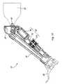
- FIG. 1is a perspective view of an actuated prosthesis with a front actuator configuration.
- FIG. 2is a partially exploded perspective view of the prosthesis shown in FIG. 1 .
- FIG. 3is an exploded perspective view of the knee member and the first pivot assembly shown in FIG. 1 .
- FIG. 4is an exploded view of the trans-tibial member and the third pivot assembly shown in FIG. 1 .
- FIG. 5is a partially exploded view of the linear actuator and the second pivot assembly shown in FIG. 1 .
- FIG. 6is a diagram illustrating the geometrical model with the front actuator configuration.
- FIG. 8is a perspective view of an actuated prosthesis with a rear actuator configuration, in accordance with another possible embodiment of the present invention.
- FIG. 9is a partially exploded perspective view of the prosthesis shown in FIG. 8 .
- FIG. 10is a side view of the prosthesis shown in FIG. 8 .
- FIG. 11is an exploded perspective view of the knee member, the first pivot assembly and the second pivot assembly shown in FIG. 8 .
- FIG. 12is a partially exploded view of the trans-tibial member and the third pivot assembly shown in FIG. 8 .
- FIG. 14is a bloc diagram showing an example of a control system for the actuator of the prosthesis.
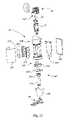
- FIG. 15is an exploded perspective view of a further embodiment of a prosthesis
- FIG. 16is a view similar to FIG. 15 on an enlarged scale of structural components of the prosthesis of FIG. 15 ,
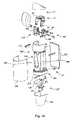
- FIG. 17is a view similar to FIG. 15 on an enlarged scale of the motive components of the prosthesis of FIG. 15 ,
- FIG. 18is a longitudinal side section of the prosthesis of FIG. 15 .
- FIG. 19is a view on the line XIX-XIX of FIG. 18 .
- FIG. 20is a view on the line XX-XX of FIG. 18 .
- FIG. 21is a view on the line XXI-XXI of FIG. 18 .
- the appended figuresshow three alternative embodiments of an actuated prosthesis ( 10 ) implemented as a leg prosthesis for an above knee amputee. It should be understood that the present invention is not limited to these illustrated implementations since various changes and modifications may be effected herein without departing from the scope of the appended claims and the principles and concepts described may be applied to prosthesis to replicate other limbs such as an arm. For clarity and ease of description, terminology relating to the use as a leg has been utilized but it will be understood that terminology applicable to the equivalent functions in other limbs may be used. For example, reference to a “knee” could be described equally with respect to an “elbow” if the prosthesis is an arm.
- the prosthesis ( 10 )has three alternative configurations, one being a front actuator configuration, another being a rear actuator configuration and the other being an inverted actuator configuration.
- the front actuator configurationis preferred.
- FIGS. 1 to 7show the prosthesis ( 10 ) with the front actuator configuration while FIGS. 8 to 13 show the prosthesis ( 10 ) with the rear actuator configuration.
- FIGS. 15 to 21show the inverted actuator configuration.
- FIGS. 1 and 2show the basic components of the prosthesis ( 10 ), which include a primary joint referred to as a knee member ( 12 ), an elongate structural member referred to as an elongated trans-tibial member ( 14 ), and a linear actuator ( 16 ) acting between the knee member ( 12 ) and the trans-tibial member ( 14 ) to cause relative movement between them.
- the prosthesis ( 10 )also comprises a socket connector assembly ( 17 ) for connecting a socket ( 18 ) on the knee member ( 12 ) and a connector assembly ( 19 ) for connecting to a terminal portion of a limb such as an artificial foot ( 20 ) under a bottom end of the trans-tibial member ( 14 ).
- the socket ( 18 )must achieve adequate effort transfers between the prosthesis ( 10 ) and the amputee's stump.
- the design of the socket ( 18 )is usually a custom operation in order to achieve an optional load transmission, stability and efficient control for the stump's mobility.
- the socket ( 18 )is generally held in place on the stump of the user by a suction effect created by an appropriate system such as, for example, a flexible suction liner of type “Thermolyn” manufactured by the Otto Bock Inc.
- the prosthesis ( 10 )can otherwise use any suitable sockets available on the market.
- the socket assembly connector ( 17 ) for connecting the socket ( 18 )may comprise a bottom socket connector ( 22 ) provided over the knee member ( 12 ).
- the bottom socket connector ( 22 )is preferably removably connected by means of fasteners, for instance screws or bolts.
- the exact type of bottom socket connector ( 22 )may vary.
- An exampleis a connector having a standard male pyramid configuration, such as male pyramid model 4R54 manufactured by Otto Bock Inc.
- Another exampleis the sliding connector with male pyramid model 2054-2 manufactured by Ossur Inc.
- the socket ( 18 )would then be equipped with a corresponding upper connector which fits over the bottom male connector ( 22 ).
- Other types of connectorsmay be used as well.
- the knee member ( 12 )provides the junction between the socket ( 18 ) and the trans-tibial member ( 14 ) with at least one degree of freedom in rotation.
- the knee member ( 12 ) range of motionis preferably about 105 degrees, where zero degree is at full extension and 105 degrees is at maximal knee flexion.
- FIG. 3shows an enlarged view of the knee member ( 12 ).
- the knee member ( 12 )is preferably a fork-shaped item, with two flanges ( 24 ) projecting from an upper plate ( 26 ).
- the upper plate ( 26 )includes four threaded holes ( 28 ) for the removable fasteners of the bottom socket connector ( 22 ).
- the knee member ( 12 )is connected to the trans-tibial member ( 14 ) by means of a first pivot assembly ( 30 ).
- the first pivot assembly ( 30 )operatively connects the trans-tibial member ( 14 ) to the knee member ( 12 ), thereby making possible a relative rotation between these two parts.
- the first pivot assembly ( 30 )can also be polycentric. This means that the movement between the knee member ( 12 ) and the trans-tibial member ( 14 ) is not purely rotational but follows a much more complex pattern.
- the right and left sides of the partscan further be slightly different, thereby causing a slight torsion movement around a vertical axis. Nevertheless, the general overall movement remains substantially a rotation around a pivot axis.
- the first pivot assembly ( 30 )defines a first pivot axis ( 31 ) that is substantially perpendicular to a main longitudinal axis ( 15 ) extending along the length of trans-tibial member ( 14 ) in the frontal plane, as shown in FIG. 1 .
- This first pivot assembly ( 30 )comprises an axle ( 32 ) supported by two bearings ( 34 ), each mounted in a corresponding housing ( 36 ) in the flanges ( 24 ) of the knee member ( 12 ).
- An example of bearing ( 34 )is a single groove-bearing model 6300-ZZ manufactured by NSK Inc. Of course, other types of bearings ( 34 ) may be used as well.
- a 10 mm shoulder nut ( 37 ) and a set of external spacers ( 35 )retain the bearings ( 34 ) on threaded ends of the axle ( 32 ).
- An optical switch support ( 38 ), shown in FIGS. 2 , 4 and 7is mounted around the axle ( 32 ) between the two flanges ( 24 ) of the knee member ( 12 ). The support ( 38 ) is described later in the description.
- a set of energy absorption bumpers ( 44 )is provided at the back side of the knee member ( 12 ) to prevent out of range motion.
- bumpers ( 44 )can be, for example, bumper model GBA-1 manufactured by Tecspak Inc. Of course, other types of bumpers ( 44 ) may be used as well. They are mounted on corresponding brackets ( 42 ) located on the side and the front of the upper plate ( 26 ) of the knee member ( 12 ). The brackets ( 42 ) are also used to support connectors ( 78 ) which are described later in the description.
- the trans-tibial member ( 14 )includes three main sections, namely an upper section ( 14 A), a middle section ( 14 B), and a bottom section ( 14 C).
- the upper section ( 14 A) of the trans-tibial member ( 14 )is preferably a fork-shaped item with two flanges ( 50 ) projecting from a mounting base ( 52 ).
- the mounting base ( 52 )is rigidly connected to a pair of trans-tibial post bars ( 54 ).
- a back plate ( 56 )is provided at the back.
- the pair of bars ( 54 ) and the back plate ( 56 )are part of the middle section ( 14 B). They are both connected to the bottom section ( 14 C), which is itself formed from two parts ( 60 , 62 ).
- the first part ( 60 )is a somewhat U-shaped part under which the second part ( 62 ) is attached.
- the second part ( 62 )is an extension under which the artificial foot ( 20 ) is provided.
- the foot connector assembly ( 19 ) for connecting the artificial foot ( 20 )includes a set of threaded holes in which screws are inserted. Other types of connectors may be used.
- the artificial foot ( 20 )may be, for example, a standard 26 cm Trustep prosthetic foot manufactured by College Park Industries Inc. or Allurion model ALX5260 prosthetic foot manufactured by Ossur Inc. Other types of articulated or non-articulated artificial foot ( 20 ) may be used if the selected prosthetic foot provides approximately at least the same dynamical response as the ones mentioned here above.
- the design of the prosthesis ( 10 )is modular and consequently, it can be adjusted to any morphology.
- the artificial foot ( 20 )may have an exposed metal or composite structure. It may also have a cosmetic covering that gives it the appearance of a human ankle and foot.
- the pair of bars ( 54 ) and the back plate ( 56 )provide a space ( 58 ) in which most of the actuator ( 16 ) is located.
- the various electronic and electric componentsmay also be attached on either sides of the back plate ( 56 ). This compact arrangement keeps the overall dimensions within that of a normal human leg.
- the linear actuator ( 16 )is shown in FIG. 5 .
- the upper end ( 16 A) of the actuator ( 16 )is connected to the knee member ( 12 ) by a pivot assembly 80 and the bottom end ( 16 B) is connected to the bottom section ( 14 C) of the trans-tibial member ( 14 ).
- the function of the actuator ( 16 )is to supply the prosthesis ( 10 ) with the necessary mechanical energy to execute, in a sagittal plane, the angular displacements synchronized with the amputee's locomotion.
- the linear motion of the actuator ( 16 )is used to control the angle of the knee member ( 12 ) with reference to the trans-tibial member ( 14 ).
- the actuator ( 16 )includes an electrical motor ( 70 ) coupled with a mechanism ( 72 , 74 ) to transfer rotational motion into linear motion.
- motor ( 70 )is the model BN2328EU manufactured by Poly-Scientific.
- the motor ( 70 )operates a screw ( 72 ) engaged to a fixed follower ( 74 ) at the bottom of the actuator ( 16 ).
- the follower ( 74 )is held by a follower support ( 76 ).
- the follower ( 74 ) and the follower support ( 76 )constitute the bottom end ( 16 B) of the actuator ( 16 ).
- the screw ( 72 )is rotated in or out of the follower ( 74 ). This pushes or pulls the knee member ( 12 ), thereby causing a relative rotation between the knee member ( 12 ) and the trans-tibial member ( 14 ).
- the choice of the linear actuator ( 16 )is primarily based on weight versus torque ratio and speed of available motor technologies. It is preferred over a direct drive system coupled directly to the knee member ( 12 ) because it takes less space for the torque requirement in human locomotion. It was found that ideally, the actuator ( 16 ) must be capable of supplying a continuous force of about 515 N and a peak force of about 2250 N.
- the second pivot assembly ( 80 )operatively connects the upper end ( 16 A) of the actuator ( 16 ) to the knee member ( 12 ).
- the second pivot assembly ( 80 )defines a second pivot axis ( 81 ) that is substantially parallel to the first pivot axis ( 31 ). It is also spaced from the plane defined by its first pivot axis ( 31 ) and the main longitudinal axis ( 15 ).
- An example of this configurationis schematically illustrated in FIG. 6 .
- This diagramrepresents the various pivot axes.
- the first pivot axis ( 31 )is identified as “O”.
- the second pivot axis ( 81 )is identified with the letter “C”. Both axes (C, 0) are spaced apart by the distance “r”. This distance creates a lever arm allowing the actuator ( 16 ) to move the trans-tibial member ( 14 ) with reference to the knee member ( 12 ).
- FIG. 5shows that the second pivot assembly ( 80 ) comprises a bearing ( 82 ) inserted in a mechanical connector ( 84 ) forming the upper end ( 16 A) of the actuator ( 16 ).
- the bearing ( 82 )may be a needle bearing, for example needle bearing model NK14/16 manufactured by INA Inc. It is held in place by means of shoulder screws ( 86 ) and aluminum spacers ( 88 ). It was found that ideally, the bearing ( 82 ) must withstand a static charge up to about 11500 N (2600 lbf) and allows for a typical misalignment of 1 to 3.
- the needle bearing ( 82 )is preferred since it has practically no mechanical play and a low coefficient of friction when compared to bushing or rod ends.
- An axle ( 90 )links the mechanical connector ( 84 ) to corresponding holes in the flanges ( 24 ) of the knee member ( 12 ).
- the mechanical connector ( 84 )is secured over the motor ( 70 ) using a load cell ( 92 ), which is described later in the description.
- the bottom end ( 16 B) of the actuator ( 16 )is operatively connected to the trans-tibial member ( 14 ) using a third pivot assembly ( 100 ), as shown in FIGS. 4 and 5 .
- the third pivot assembly ( 100 )defines a third pivot axis ( 101 ) and also preferably comprises one or more needle bearings ( 102 ), each mounted in a corresponding housing ( 64 ) provided in the first part ( 60 ) of the bottom section ( 14 C) of the trans-tibial member ( 14 ).
- Two standard needle bearings ( 102 )may be used for that purpose, for example needle bearing model NK14/16 manufactured by INA Inc. Of course, other types of bearings may be used as well in the second ( 80 ) and the third pivot assembly ( 100 ).
- a set of screws ( 106 ) and spacers ( 108 )completes the third pivot assembly ( 100 ).
- the various structural parts of the prosthesis ( 10 )are preferably made of a light material, for instance aluminum or a composite material, such as carbon fiber, fiberglass or the like.
- a particularly suitable materialis thermally treated 6061T6 aluminum.
- the various partsare preferably screwed together, although they may be welded and otherwise secured together Screwing the parts together is preferred since this increases manufacturability, facilitates servicing and replacement of the parts, and usually improves the overall aesthetics.
- FIG. 7shows the specialized mechanical support ( 38 ) appearing in FIGS. 2 and 4 .
- This specialized mechanical support ( 38 )is used firstly to fix the optical switches as explained hereafter.
- the specialized mechanical support ( 38 )is used to facilitate the transition between the part of a cable (not shown) between the relatively fixed section of the prosthesis ( 10 ) and the relatively movable section thereof.
- a similar connector ( 78 )is provided on the motor ( 70 ).
- a two-part wire clamp ( 39 A, 39 B) on parts ( 254 )allows to hold the wire on the support ( 38 ).
- the actuator ( 16 ) shown in the prosthesis of FIGS. 1 to 7is controlled by the control system ( 200 ) shown in FIG. 14 .
- This figurefirst shows a set of artificial proprioceptors ( 210 ), which are sensors used to capture information in real time about the dynamics of the amputee's locomotion.
- the set of artificial proprioceptors ( 210 )provide sensing information to a controller ( 220 ).
- the controller ( 220 )determines the joint trajectories and the required forces that must be applied by the actuator ( 16 ).
- the set-point (joint trajectories and the required forces)is then sent to the actuator ( 16 ) via the power drive ( 230 ) itself connected to the power supply ( 240 ).
- the power supply ( 240 )can be, for example, a flexible battery pack belt such as the Lighting Powerbelt model, manufactured by Cine Power International Ltd.
- Other examples of power supply ( 240 )are the battery model SLPB526495 manufactured by Worley Inc. and the super capacitors manufactured by Cap-XX.
- Examples of power drive ( 230 )are the 5121 model, manufactured by Copley Controls Corporation Inc. and the model BE40A8 manufactured by Advanced Motion Control. It should be noted that the design of the power supply ( 240 ) and that of the power drive ( 230 ) are not limited to the devices mentioned here above and could be performed by any custom or commercial products if the selected devices meet the electrical specification of the selected actuator ( 16 ) used with the prosthesis ( 10 ).
- the prosthesis ( 10 )further includes a set of sensors ( 250 ) to provide feedback information to the controller ( 220 ).
- This feedbackallows the controller ( 220 ) to adjust the forces and various other parameters.
- parameters that can be monitoredare the relative angle of the knee member ( 12 ) and the torque at the knee member ( 12 ) being exerted by the actuator ( 16 ).
- Other types of measurementsmay be taken.
- the measurement of the relative angle of the knee member ( 12 )can be taken, for example, by a standard commercially available incremental optical encoder ( 260 ) such as a reading head model EM1-0-250 and a Mylar® strip ( 262 ) marked with evenly spaced increments model LIN-250- 16 -S2037 manufactured by US Digital Inc.
- the optical switches ( 252 )are fixed on the first pivot axis ( 31 ) and are used to set the reference angular position of the knee member ( 12 ). Once this reference position is known, the optical encoder information is used to compute the knee member ( 12 ) angle via motor rotation, roller-screw pitch and prosthesis geometry. Moreover, the optical switches ( 252 ) are used to prevent out of range motion by sending a signal to the controller ( 220 ) when the knee member ( 12 ) approaches critical positions. Of course, the optical switches ( 252 ) may be use for other purposes according to the nature of the command associated with the switches detection.
- Another possible way of measuring the relative angle of the knee member ( 12 )is by using a combination of an absolute optical encoder such as, for example, encoder model E2-512-250-i manufactured by US Digital Inc. and optical switches.
- an absolute optical encodersuch as, for example, encoder model E2-512-250-i manufactured by US Digital Inc.
- optical switchesAn example of these switches is the switch model PM-L24 manufactured by SUNX.
- the measurement of the torqueis taken from the force being exerted by the actuator ( 16 ) measured by a load cell ( 92 ).
- An example of the load cellis the model LC 202 1 K manufactured by Omegadyne.
- a connector on the motor ( 70 )links the internal sensor to the cable. It should be noted that the sensors ( 250 ) of the prosthesis ( 10 ) are not limited to the above-mentioned devices and can be performed by other suitable instruments.
- the knee assembly ( 12 )is connected to the socket ( 18 ) and the pivot assembly ( 30 ) permits relative motion between the trans-tibial member and the knee about a generally transverse horizontal axis.
- Rotation of the knee member relative to the trans-tibial member ( 14 )is controlled by operation of the actuator ( 16 ).
- the actuator ( 16 )acts between the pivot assembly ( 80 ) on the knee member ( 12 ) and the pivot assembly ( 100 ) at the lower end of the trans-tibial member ( 14 ) so that changes in the length of the actuator ( 16 ) will cause a corresponding rotation about the pivot ( 30 ).
- the length of the actuator ( 16 )is adjusted by control signals from the controller ( 220 ) that supplies power to the motor ( 70 ) to rotate the screw ( 72 ) in one direction or the other.
- Rotation of the screw ( 72 )causes the follower ( 74 ) to move along the screw ( 72 ) and this motion is transferred through the connection provided by the pivot assembly ( 100 ) to the trans-tibial member ( 14 ).
- Thiscauses a corresponding rotation of the knee member ( 12 ) and trans-tibial member ( 14 ) about the pivot axis ( 30 ) to provide the desired motion.
- the rate and extent of rotationmay be adjusted through control signals to the motor ( 70 ) and the sensors embodied in the prosthesis provide the feedback to the controller ( 220 ).
- FIGS. 8 to 13show the prosthesis ( 10 ) in accordance with a second possible embodiment.
- Thisillustrates an example of a prosthesis ( 10 ) with a rear actuator configuration.
- This embodimentis very similar to the one using the front actuator configuration. It is illustrated with another kind of actuator ( 16 ) and another model of artificial foot ( 20 ).
- the middle section ( 14 B) of the trans-tibial member ( 14 )uses four bars ( 54 ) instead of two. It does not have a back plate. Moreover, no bottom extension is provided on the trans-tibial member ( 14 ).
- the trans-tibial member ( 14 )also has a shell type architecture composed, for example, of 1 ⁇ 2′′ trans-tibial post bars ( 54 ) linking together the knee member ( 12 ) and the artificial foot ( 20 ).
- the actuator ( 16 )could be a standard linear motor ( FIG. 5 ) or a serial elastic actuator (SEA) ( FIG. 8 ) equipped with a customized commercially available motor ( 70 ) although the prosthesis ( 10 ) is designed such that it can receive any type of linear actuator ( 16 ) of the same approximate size.
- the SEA actuator ( 16 ) ( FIG. 8 )has a ball screw transmission system including a screw ( 72 ) coupled with an elastic device ( 110 ) of known characteristics. This actuator ( 16 ) ( FIG.
- the SEA actuator ( 16 )( FIG. 8 ) was developed by Gill Pratt of the MIT Leg Laboratory and has been patented in 1997 as U.S. Pat. No. 5,650,704. In one implementation, it was provided with a Litton BN23-28 motor ( 70 ) and a 3 ⁇ 8′′ diameter with 1 ⁇ 8′′ pitch ball screw ( 72 ).
- the SEA actuator ( 16 )( FIG. 8 ) is commercialized by Yobotic Inc.
- the torquemay be measured, for example, by a standard commercially available potentiometer measuring the compression of the elastic devices of the actuator ( 16 ) such as the conductive plastic resistance elements model PTN025 manufactured by Novotechnik Inc.
- the measurement of the angle between the knee member ( 12 ) and trans-tibial member ( 14 )can also be computed directly from the measurement of the length of the actuator ( 16 ) and the known geometry of the prosthesis.
- FIG. 13illustrates the geometrical model of the rear actuator configuration. It is essentially similar to that of the front actuator configuration as shown in FIG. 6 .
- the actuator ( 16 )has been arranged with the motor ( 70 ) adjacent to the knee member ( 12 ) and the follower ( 74 ) extending to the lower, ankle region of the trans-tibial member ( 14 ).
- Such an arrangementsimplifies the routing of the power and control lines and generally allows a tapering profile toward the ankle to conform to the natural profile of a leg.
- the motor ( 70 )moves with the pivot assembly ( 80 ) through the range of motion of the prosthesis and accordingly the swept volume of the motor must be accommodated in the design of the knee member ( 12 ).
- FIGS. 15 to 21a further embodiment of the prosthesis ( 10 ) is shown in FIGS. 15 to 21 in which like components will be described by like reference numerals with a prime suffix (′) for clarity.
- a prosthesis ( 10 ′)has a knee member ( 12 )′ formed as a U shaped member with flanges ( 24 ′) extending from the upper plate ( 26 ′).
- the lower ends of the flanges ( 24 ′)receive respective bearings ( 34 ′) forming part of the pivot assembly ( 30 ′) that connects the knee member ( 12 ′) to the trans-tibial member ( 14 ′).
- a socket connector assembly ( 17 ′)is secured to the upper plate ( 26 ′) for connection to an appropriate socket.
- the trans-tibial member ( 14 ′)has an upper section ( 14 A′) formed by a pair of spaced webs ( 300 ) with bores ( 302 ) to receive the bearings ( 34 ′) of the pivot assembly ( 30 ′).
- the webs ( 300 )are secured to shoulders, not shown, at the upper end of the middle section ( 14 B′).
- the middle section ( 14 B′)is formed as an open channel member ( 304 ) with laterally spaced side walls ( 306 ) interconnected by an integrally formed front wall ( 308 ).
- the channel member ( 304 )is closed by a back wall ( 310 ), which is removable to permit access to the interior of the channel member ( 304 ).
- the middle section ( 14 B′)thus provides a lightweight structural member of high torsional and bending strength to meet the loading placed upon it.
- the upper and lower ends ( 312 , 314 ) respectively of the channel member ( 304 )are enlarged to receive the upper section ( 14 A′) and lower section ( 14 B′) and thereby define a waisted intermediate portion ( 316 ).
- the side walls ( 306 ) in the waisted portion ( 316 )have generally planar flanks that support energy storage modules ( 320 ), typically battery packs, on either side of the channel member ( 304 ).
- the front wall ( 308 )is also formed with a planar facet ( 314 ) to receive a control board ( 319 ) associated with the operation of the actuator ( 16 ′) and to regulate power flow to and from the energy storage modules ( 320 ).
- the back wall ( 310 )also serves as a mounting point for a further control board ( 322 ) utilized in the control of the actuator ( 16 ′).
- the shell ( 324 )protects the components mounted on the waisted intermediate portion ( 316 ) as well as being contoured to conform to the appearance of a human leg.
- the lower section ( 14 C′) of the trans-tibial member ( 14 ′)includes a mounting plate ( 330 ) received within the enlarged lower end ( 314 ).
- the plate ( 330 )is bolted the lower ends ( 314 ) of the channel member ( 304 ) and to the power drive ( 322 ) utilized in the control of the actuator ( 16 ′) which in turn is secured to the middle section ( 14 B)′.
- a socket ( 334 )is mounted on the underside of the plate ( 330 ) to receive a tubular member ( 336 ) of the foot connector assembly ( 20 ′).
- the tubular member ( 336 )extends to a male socket formed on the foot ( 20 ′) and its length may be adjusted to tailor the prosthesis to a particular individual.
- a skirt ( 338 )extends around the tubular member ( 336 ) for cosmetic considerations.
- the actuator ( 16 ′)includes a motor ( 70 ′) with a screw ( 72 ′).
- the actuator ( 16 ′)is located within the interior of the middle section ( 14 B′) so as to be surrounded by the walls ( 308 , 310 , 312 ), with the screw ( 72 ′) extending beyond the upper end ( 312 ) and between the flanges ( 26 ′) of the knee member ( 12 ′).
- the screw ( 72 ′)engages a follower ( 74 ′) forming part of the pivot assembly ( 80 ′) that is connected to the knee member ( 12 ′) at a location spaced from the pivot assembly ( 30 ′).
- the motor ( 70 ′)is similarly connected through a pivot assembly ( 100 ′) to the lower end ( 314 ) of the middle section ( 14 B′) at mounting points ( 340 ) ( FIG. 16 ) that receive the bearings of the pivot assembly ( 100 ′).
- the operation of the inverted actuatoris essentially the same as that of the front mounted actuator with rotation of the motor ( 70 ′) causing a change in the effective length of the actuator ( 16 ′) and a corresponding rotation of the knee member ( 12 ′) relative to trans-tibial member ( 14 ′).
- the motor ( 70 ′)swings about its pivot assembly ( 100 ′) but does not translate along the axis of the prosthesis ( 10 ′).
- the swept volume of the motor through the range of movementis thus reduced allowing better utilisation of the space available.
- the mass distribution in the prosthesisremains substantially uniform in view of the lack of translation of the motor to provide a more natural feel to the operation of the prosthesis.
- the integration of the energy module and control boards on the middle sectionalso provides a more self contained unit and simplifies the routing of the control and power transmission.
- the lever arm bris assumed to be maximum at a knee angle ⁇ k of 35 degrees.
- the geometrical calculation of the mechanical designare based on the setting of the distance r, the length L T , the distance d T and the angle ⁇ fix . Therefore, these parameters are defined in accordance with the anthropomorphic measurements of the amputee and the selected actuator ( 16 ).
- Equation 5For an angle ⁇ fix , the optimal value for a maximum lever arm b r is found when Equation 5 is at a maximum value, that is:
- the optimal angle ⁇ fixis preferably set at 125 ⁇ 3 degrees.
Landscapes
- Health & Medical Sciences (AREA)
- Transplantation (AREA)
- Vascular Medicine (AREA)
- Life Sciences & Earth Sciences (AREA)
- Oral & Maxillofacial Surgery (AREA)
- Engineering & Computer Science (AREA)
- Biomedical Technology (AREA)
- Heart & Thoracic Surgery (AREA)
- Veterinary Medicine (AREA)
- Cardiology (AREA)
- Animal Behavior & Ethology (AREA)
- General Health & Medical Sciences (AREA)
- Public Health (AREA)
- Orthopedic Medicine & Surgery (AREA)
- Prostheses (AREA)
- Transition And Organic Metals Composition Catalysts For Addition Polymerization (AREA)
- Medicines Containing Plant Substances (AREA)
- Steroid Compounds (AREA)
Abstract
Description
- a primary joint member; a socket connector assembly for connecting a socket to said primary joint member;
- an elongated structural member having opposite ends spaced apart along, a main longitudinal axis;
- a connector assembly for connecting a terminal portion to an end of said structural member;
- a pivot assembly for operatively connecting the structural member to the primary joint member to permit relative rotation between said primary joint member and said structural member about an first axis defined by said pivot assembly;
- a linear actuator connected at one end to said structural member and at the opposite end to said primary joint member at a location spaced from said pivot assembly, whereby extension or retraction of said actuator induces a corresponding rotation of said primary joint member relative to said structural member about said pivotal axis.
- a geometrical volume corresponding to the anthropometrical volume of a natural shank of an individual having a weight of 70 kg and a height of 170 cm;
- a maximal distance r set at 0.055 m, that is r<0.055 m;
- a minimal and a maximal length LTset at 0.3 m and 0.4 m respectively, that is 0.3 m<LT<0.4 m; and
- a minimal and a maximal distance dTset at −0.015 m and +0.015 m, that is −0.015 m<dT<+0.015 m.
β=π−θfix−α−θK Equation 1
LA=√{square root over (LT2+dT2)} Equation 2
L2=LA2+r2−2·LAr·cos β Equation 4
where
- θKKnee angle, ∠DOA
- r Distance between the center of rotation “O” of the knee member (12) and the attachment point of the actuator (16) on the knee member (12)
- θfixAngle between r and the stump's center axis, ∠EOC
- LADistance between the center of rotation of the knee member (12) and the attachment point of the actuator (16) on the trans-tibial member (14)
OB - LTLength between the center of rotation of the knee member (12) and the attachment point of the trans-tibial member (14)
OA - dTDistance between the center axis of the trans-tibial member (14) and the actuator (16) attachment point of the trans-tibial member (14),
AB - α Angle formed between LT, LA: ∠AOB
- L Length of the actuator (16),
BC - β Angle formed between LA, r: ∠BOC
- bTLever arm of the actuator (16) versus the first pivot axis (31)
where θfix=π−π−θK−β
where +π/2 and −π/2 correspond to the rear and the front actuator configuration respectively.
Claims (22)
Priority Applications (11)
| Application Number | Priority Date | Filing Date | Title |
|---|---|---|---|
| US10/721,764US7736394B2 (en) | 2002-08-22 | 2003-11-25 | Actuated prosthesis for amputees |
| EP04802212AEP1689332B1 (en) | 2003-11-25 | 2004-11-25 | Actuated prosthesis for amputees |
| CN2004800391438ACN1901858B (en) | 2003-11-25 | 2004-11-25 | Actuated prosthesis for amputees |
| JP2006540123AJP5128132B2 (en) | 2003-11-25 | 2004-11-25 | Actuated prosthesis for amputee |
| DE602004032168TDE602004032168D1 (en) | 2003-11-25 | 2004-11-25 | Betätigte prothese für amputierte |
| CA2546858ACA2546858C (en) | 2003-11-25 | 2004-11-25 | Actuated prosthesis for amputees |
| PCT/CA2004/002035WO2005051248A1 (en) | 2003-11-25 | 2004-11-25 | Actuated prosthesis for amputees |
| AU2004292345AAU2004292345B2 (en) | 2003-11-25 | 2004-11-25 | Actuated prosthesis for amputees |
| AT04802212TATE504270T1 (en) | 2003-11-25 | 2004-11-25 | ACTUATED PROSTHESIS FOR AMPUTEES |
| KR1020067012393AKR100834050B1 (en) | 2003-11-25 | 2004-11-25 | Actuated Prosthesis for amputees |
| US12/815,166US9358137B2 (en) | 2002-08-22 | 2010-06-14 | Actuated prosthesis for amputees |
Applications Claiming Priority (5)
| Application Number | Priority Date | Filing Date | Title |
|---|---|---|---|
| US40528102P | 2002-08-22 | 2002-08-22 | |
| US42426102P | 2002-11-06 | 2002-11-06 | |
| US45355603P | 2003-03-11 | 2003-03-11 | |
| US10/463,495US7314490B2 (en) | 2002-08-22 | 2003-06-17 | Actuated leg prosthesis for above-knee amputees |
| US10/721,764US7736394B2 (en) | 2002-08-22 | 2003-11-25 | Actuated prosthesis for amputees |
Related Parent Applications (1)
| Application Number | Title | Priority Date | Filing Date |
|---|---|---|---|
| US10/463,495Continuation-In-PartUS7314490B2 (en) | 2002-08-22 | 2003-06-17 | Actuated leg prosthesis for above-knee amputees |
Related Child Applications (1)
| Application Number | Title | Priority Date | Filing Date |
|---|---|---|---|
| US12/815,166ContinuationUS9358137B2 (en) | 2002-08-22 | 2010-06-14 | Actuated prosthesis for amputees |
Publications (2)
| Publication Number | Publication Date |
|---|---|
| US20040181289A1 US20040181289A1 (en) | 2004-09-16 |
| US7736394B2true US7736394B2 (en) | 2010-06-15 |
Family
ID=34633260
Family Applications (2)
| Application Number | Title | Priority Date | Filing Date |
|---|---|---|---|
| US10/721,764Expired - LifetimeUS7736394B2 (en) | 2002-08-22 | 2003-11-25 | Actuated prosthesis for amputees |
| US12/815,166Expired - Fee RelatedUS9358137B2 (en) | 2002-08-22 | 2010-06-14 | Actuated prosthesis for amputees |
Family Applications After (1)
| Application Number | Title | Priority Date | Filing Date |
|---|---|---|---|
| US12/815,166Expired - Fee RelatedUS9358137B2 (en) | 2002-08-22 | 2010-06-14 | Actuated prosthesis for amputees |
Country Status (10)
| Country | Link |
|---|---|
| US (2) | US7736394B2 (en) |
| EP (1) | EP1689332B1 (en) |
| JP (1) | JP5128132B2 (en) |
| KR (1) | KR100834050B1 (en) |
| CN (1) | CN1901858B (en) |
| AT (1) | ATE504270T1 (en) |
| AU (1) | AU2004292345B2 (en) |
| CA (1) | CA2546858C (en) |
| DE (1) | DE602004032168D1 (en) |
| WO (1) | WO2005051248A1 (en) |
Cited By (57)
| Publication number | Priority date | Publication date | Assignee | Title |
|---|---|---|---|---|
| US20050070834A1 (en)* | 2003-09-25 | 2005-03-31 | Massachusetts Institute Of Technology | Active Ankle Foot Orthosis |
| US20090299480A1 (en)* | 2007-01-05 | 2009-12-03 | Victhom Human Bionics Inc. | Joint Actuation Mechanism for a Prosthetic and/or Orthotic Device Having a Compliant Transmission |
| US20100004757A1 (en)* | 2008-07-01 | 2010-01-07 | Ossur Hf | Smooth rollover insole for prosthetic foot |
| US20100160844A1 (en)* | 2007-01-05 | 2010-06-24 | Benoit Gilbert | High Torque Active Mechanism for Orthotic and/or Prosthetic Devices |
| US20100286796A1 (en)* | 2009-05-05 | 2010-11-11 | Ossur Hf | Control systems and methods for prosthetic or orthotic devices |
| US20100324698A1 (en)* | 2009-06-17 | 2010-12-23 | Ossur Hf | Feedback control systems and methods for prosthetic or orthotic devices |
| US20110098606A1 (en)* | 2005-02-02 | 2011-04-28 | Ossur Hf | Sensing systems and methods for monitoring gait dynamics |
| US20110125290A1 (en)* | 2007-01-19 | 2011-05-26 | Victhom Human Bionics Inc. | Reactive Layer Control System for Prosthetic and Orthotic Devices |
| US8323354B2 (en) | 2003-11-18 | 2012-12-04 | Victhom Human Bionics Inc. | Instrumented prosthetic foot |
| US8419804B2 (en) | 2008-09-04 | 2013-04-16 | Iwalk, Inc. | Hybrid terrain-adaptive lower-extremity systems |
| US8500823B2 (en) | 2005-03-31 | 2013-08-06 | Massachusetts Institute Of Technology | Powered artificial knee with agonist-antagonist actuation |
| US8512415B2 (en) | 2005-03-31 | 2013-08-20 | Massachusetts Institute Of Technology | Powered ankle-foot prothesis |
| US8551184B1 (en) | 2002-07-15 | 2013-10-08 | Iwalk, Inc. | Variable mechanical-impedance artificial legs |
| US8555715B2 (en) | 2010-07-07 | 2013-10-15 | össur hf. | Ground contact sensing systems and methods for lower-limb orthotic and prosthetic devices |
| US8617254B2 (en) | 2004-03-10 | 2013-12-31 | Ossur Hf | Control system and method for a prosthetic knee |
| US8657886B2 (en) | 2004-02-12 | 2014-02-25 | össur hf | Systems and methods for actuating a prosthetic ankle |
| US8702811B2 (en) | 2005-09-01 | 2014-04-22 | össur hf | System and method for determining terrain transitions |
| US8734528B2 (en) | 2005-03-31 | 2014-05-27 | Massachusetts Institute Of Technology | Artificial ankle-foot system with spring, variable-damping, and series-elastic actuator components |
| US8814949B2 (en) | 2005-04-19 | 2014-08-26 | össur hf | Combined active and passive leg prosthesis system and a method for performing a movement with such a system |
| WO2014088505A3 (en)* | 2012-12-06 | 2014-10-02 | Centri Ab | Knee joint prosthesis |
| US8864846B2 (en) | 2005-03-31 | 2014-10-21 | Massachusetts Institute Of Technology | Model-based neuromechanical controller for a robotic leg |
| US8870967B2 (en) | 2005-03-31 | 2014-10-28 | Massachusetts Institute Of Technology | Artificial joints using agonist-antagonist actuators |
| US8915968B2 (en) | 2010-09-29 | 2014-12-23 | össur hf | Prosthetic and orthotic devices and methods and systems for controlling the same |
| US9032635B2 (en) | 2011-12-15 | 2015-05-19 | Massachusetts Institute Of Technology | Physiological measurement device or wearable device interface simulator and method of use |
| US9044346B2 (en) | 2012-03-29 | 2015-06-02 | össur hf | Powered prosthetic hip joint |
| US9060883B2 (en) | 2011-03-11 | 2015-06-23 | Iwalk, Inc. | Biomimetic joint actuators |
| US9060884B2 (en) | 2011-05-03 | 2015-06-23 | Victhom Human Bionics Inc. | Impedance simulating motion controller for orthotic and prosthetic applications |
| US9078774B2 (en) | 2004-12-22 | 2015-07-14 | össur hf | Systems and methods for processing limb motion |
| US9221177B2 (en) | 2012-04-18 | 2015-12-29 | Massachusetts Institute Of Technology | Neuromuscular model-based sensing and control paradigm for a robotic leg |
| US9333097B2 (en) | 2005-03-31 | 2016-05-10 | Massachusetts Institute Of Technology | Artificial human limbs and joints employing actuators, springs, and variable-damper elements |
| US9351855B2 (en) | 2008-06-16 | 2016-05-31 | Ekso Bionics, Inc. | Powered lower extremity orthotic and method of operation |
| US9358137B2 (en) | 2002-08-22 | 2016-06-07 | Victhom Laboratory Inc. | Actuated prosthesis for amputees |
| WO2016172057A1 (en) | 2015-04-20 | 2016-10-27 | Össur Iceland Ehf | Electromyography with prosthetic or orthotic devices |
| US9526636B2 (en) | 2003-11-18 | 2016-12-27 | Victhom Laboratory Inc. | Instrumented prosthetic foot |
| US9561118B2 (en) | 2013-02-26 | 2017-02-07 | össur hf | Prosthetic foot with enhanced stability and elastic energy return |
| US9649206B2 (en) | 2002-08-22 | 2017-05-16 | Victhom Laboratory Inc. | Control device and system for controlling an actuated prosthesis |
| US9687377B2 (en) | 2011-01-21 | 2017-06-27 | Bionx Medical Technologies, Inc. | Terrain adaptive powered joint orthosis |
| US9693883B2 (en) | 2010-04-05 | 2017-07-04 | Bionx Medical Technologies, Inc. | Controlling power in a prosthesis or orthosis based on predicted walking speed or surrogate for same |
| US9707104B2 (en) | 2013-03-14 | 2017-07-18 | össur hf | Prosthetic ankle and method of controlling same based on adaptation to speed |
| US9737419B2 (en) | 2011-11-02 | 2017-08-22 | Bionx Medical Technologies, Inc. | Biomimetic transfemoral prosthesis |
| US9839552B2 (en) | 2011-01-10 | 2017-12-12 | Bionx Medical Technologies, Inc. | Powered joint orthosis |
| US9949850B2 (en) | 2015-09-18 | 2018-04-24 | Össur Iceland Ehf | Magnetic locking mechanism for prosthetic or orthotic joints |
| US10080672B2 (en) | 2005-03-31 | 2018-09-25 | Bionx Medical Technologies, Inc. | Hybrid terrain-adaptive lower-extremity systems |
| US10195057B2 (en) | 2004-02-12 | 2019-02-05 | össur hf. | Transfemoral prosthetic systems and methods for operating the same |
| US10253855B2 (en)* | 2016-12-15 | 2019-04-09 | Boston Dynamics, Inc. | Screw actuator for a legged robot |
| US10290235B2 (en) | 2005-02-02 | 2019-05-14 | össur hf | Rehabilitation using a prosthetic device |
| US10285828B2 (en) | 2008-09-04 | 2019-05-14 | Bionx Medical Technologies, Inc. | Implementing a stand-up sequence using a lower-extremity prosthesis or orthosis |
| US10307272B2 (en) | 2005-03-31 | 2019-06-04 | Massachusetts Institute Of Technology | Method for using a model-based controller for a robotic leg |
| US10390974B2 (en) | 2014-04-11 | 2019-08-27 | össur hf. | Prosthetic foot with removable flexible members |
| US10485681B2 (en) | 2005-03-31 | 2019-11-26 | Massachusetts Institute Of Technology | Exoskeletons for running and walking |
| US10531965B2 (en) | 2012-06-12 | 2020-01-14 | Bionx Medical Technologies, Inc. | Prosthetic, orthotic or exoskeleton device |
| US10537449B2 (en) | 2011-01-12 | 2020-01-21 | Bionx Medical Technologies, Inc. | Controlling powered human augmentation devices |
| US10543109B2 (en) | 2011-11-11 | 2020-01-28 | Össur Iceland Ehf | Prosthetic device and method with compliant linking member and actuating linking member |
| US10575970B2 (en) | 2011-11-11 | 2020-03-03 | Össur Iceland Ehf | Robotic device and method of using a parallel mechanism |
| US10898350B2 (en) | 2015-11-24 | 2021-01-26 | University Of South Carolina | Dynamic linear adjustable prosthetic |
| US11278433B2 (en) | 2005-03-31 | 2022-03-22 | Massachusetts Institute Of Technology | Powered ankle-foot prosthesis |
| US11485028B2 (en)* | 2019-05-16 | 2022-11-01 | Ubtech Robotics Corp Ltd | Linear joint and legged robot having the same |
Families Citing this family (59)
| Publication number | Priority date | Publication date | Assignee | Title |
|---|---|---|---|---|
| US7198071B2 (en) | 2003-05-02 | 2007-04-03 | Össur Engineering, Inc. | Systems and methods of loading fluid in a prosthetic knee |
| US8007544B2 (en) | 2003-08-15 | 2011-08-30 | Ossur Hf | Low profile prosthetic foot |
| US7811334B2 (en)* | 2004-02-12 | 2010-10-12 | Ossur Hf. | System and method for motion-controlled foot unit |
| WO2005110293A2 (en) | 2004-05-07 | 2005-11-24 | Ossur Engineering, Inc. | Magnetorheologically actuated prosthetic knee |
| US7581454B2 (en)* | 2004-05-28 | 2009-09-01 | össur hf | Method of measuring the performance of a prosthetic foot |
| US7347877B2 (en)* | 2004-05-28 | 2008-03-25 | össur hf | Foot prosthesis with resilient multi-axial ankle |
| US8801802B2 (en) | 2005-02-16 | 2014-08-12 | össur hf | System and method for data communication with a mechatronic device |
| EP1946429B1 (en) | 2005-08-10 | 2017-06-21 | Bionic Power Inc. | Methods and apparatus for harvesting biomechanical energy |
| US7485152B2 (en) | 2005-08-26 | 2009-02-03 | The Ohio Willow Wood Company | Prosthetic leg having electronically controlled prosthetic knee with regenerative braking feature |
| US7531006B2 (en) | 2005-09-01 | 2009-05-12 | össur hf | Sensing system and method for motion-controlled foot unit |
| US8048172B2 (en)* | 2005-09-01 | 2011-11-01 | össur hf | Actuator assembly for prosthetic or orthotic joint |
| US8114168B2 (en) | 2006-09-19 | 2012-02-14 | Ossur Hf | Momentum free bearing for use in prosthetic and orthotic devices |
| EP1955679B1 (en)* | 2007-02-09 | 2013-11-06 | Semiconductor Energy Laboratory Co., Ltd. | Assist device |
| JP5119440B2 (en)* | 2007-12-26 | 2013-01-16 | 財団法人ヒューマンサイエンス振興財団 | Hip and knee joint automatic hip prosthesis |
| US7783999B2 (en)* | 2008-01-18 | 2010-08-24 | Taiwan Semiconductor Manufacturing Company, Ltd. | Electrical parameter extraction for integrated circuit design |
| AU2009269892B2 (en)* | 2008-06-16 | 2014-05-08 | Ekso Bionics, Inc. | Semi-actuated transfemoral prosthetic knee |
| US9265625B2 (en) | 2009-08-20 | 2016-02-23 | Vanderbilt University | Jointed mechanical devices |
| WO2011065608A1 (en)* | 2009-11-30 | 2011-06-03 | 한국산재의료원 | Connection structure of artificial limb and socket, using magnetic locking device |
| EP2538891B1 (en) | 2010-02-26 | 2015-04-15 | Össur HF | Prosthetic foot with a curved split |
| GB201114264D0 (en) | 2011-08-18 | 2011-10-05 | Touch Emas Ltd | Improvements in or relating to prosthetics and orthotics |
| US8736087B2 (en) | 2011-09-01 | 2014-05-27 | Bionic Power Inc. | Methods and apparatus for control of biomechanical energy harvesting |
| DE102011116751A1 (en) | 2011-10-24 | 2013-04-25 | Fraunhofer-Gesellschaft zur Förderung der angewandten Forschung e.V. | Active knee prosthesis with bevel helical gear |
| US8961618B2 (en) | 2011-12-29 | 2015-02-24 | össur hf | Prosthetic foot with resilient heel |
| US9017419B1 (en) | 2012-03-09 | 2015-04-28 | össur hf | Linear actuator |
| GB201302025D0 (en) | 2013-02-05 | 2013-03-20 | Touch Emas Ltd | Improvements in or relating to prosthetics |
| US9839534B2 (en)* | 2014-02-04 | 2017-12-12 | Rehabilitation Institute Of Chicago | Modular and lightweight myoelectric prosthesis components and related methods |
| GB201403265D0 (en) | 2014-02-25 | 2014-04-09 | Touch Emas Ltd | Prosthetic digit for use with touchscreen devices |
| GB201408253D0 (en) | 2014-05-09 | 2014-06-25 | Touch Emas Ltd | Systems and methods for controlling a prosthetic hand |
| US9999524B2 (en) | 2014-06-30 | 2018-06-19 | össur hf | Prosthetic feet and foot covers |
| CN104027225B (en)* | 2014-07-02 | 2018-12-07 | 河北工业大学 | A kind of road conditions recognition methods |
| CN104027191B (en)* | 2014-07-02 | 2016-02-03 | 河北工业大学 | A kind of road conditions recognition system of above-knee prosthesis |
| GB201417541D0 (en) | 2014-10-03 | 2014-11-19 | Touch Bionics Ltd | Wrist device for a prosthetic limb |
| AU2015360683B2 (en)* | 2014-12-08 | 2019-11-21 | Rehabilitation Institute Of Chicago | Powered and passive assistive device and related methods |
| US9731416B1 (en)* | 2015-03-11 | 2017-08-15 | Google Inc. | Legged robot passive fluid-based ankles with spring centering |
| KR101733858B1 (en) | 2015-03-27 | 2017-05-08 | 서강대학교산학협력단 | Active lower leg prosthesis device |
| USD795433S1 (en) | 2015-06-30 | 2017-08-22 | Össur Iceland Ehf | Prosthetic foot cover |
| US9994269B1 (en)* | 2015-11-12 | 2018-06-12 | Schaft Inc. | Rotatable extension for robot foot |
| US10195099B2 (en) | 2016-01-11 | 2019-02-05 | Bionic Power Inc. | Method and system for intermittently assisting body motion |
| EP3487666B1 (en)* | 2016-07-22 | 2024-11-13 | President and Fellows of Harvard College | Controls optimization for wearable systems |
| EP3506857B1 (en) | 2016-09-02 | 2025-07-09 | Touch Bionics Limited | Systems and methods for prosthetic wrist rotation |
| US11185426B2 (en) | 2016-09-02 | 2021-11-30 | Touch Bionics Limited | Systems and methods for prosthetic wrist rotation |
| US10675456B2 (en) | 2016-09-20 | 2020-06-09 | Robert Madeira | System and methods for percutaneous mechanical and/or neural interface |
| US10406000B2 (en)* | 2016-09-29 | 2019-09-10 | The Chinese University Of Hong Kong | Ankle-foot prosthesis device |
| US11696840B2 (en)* | 2016-11-10 | 2023-07-11 | The University Of Tokyo | Knee joint |
| WO2018102609A1 (en) | 2016-12-01 | 2018-06-07 | Össur Iceland Ehf | Prosthetic feet having heel height adjustability |
| US11446164B1 (en) | 2017-09-15 | 2022-09-20 | Össur Iceland Ehf | Variable stiffness mechanisms |
| US10980648B1 (en) | 2017-09-15 | 2021-04-20 | Össur Iceland Ehf | Variable stiffness mechanism and limb support device incorporating the same |
| WO2019118534A1 (en)* | 2017-12-12 | 2019-06-20 | The Texas A&M University Sytem | Lightweight, modular, powered transfemoral prosthesis |
| US10973660B2 (en) | 2017-12-15 | 2021-04-13 | Touch Bionics Limited | Powered prosthetic thumb |
| CN108143524A (en)* | 2017-12-27 | 2018-06-12 | 大连民族大学 | A kind of leg artificial limb |
| USD915596S1 (en) | 2018-04-10 | 2021-04-06 | Össur Iceland Ehf | Prosthetic foot with tapered fasteners |
| US12414867B1 (en) | 2018-06-01 | 2025-09-16 | Össur Iceland Ehf | Prosthetic feet with increased flexibility to accommodate different heel heights |
| GB2576372B (en)* | 2018-08-17 | 2023-02-01 | Blatchford Products Ltd | Lower limb prosthesis |
| US12263101B2 (en) | 2019-03-29 | 2025-04-01 | Honda Motor Co., Ltd. | Joint device |
| JP7497360B2 (en)* | 2019-08-29 | 2024-06-10 | 本田技研工業株式会社 | Coupling Device |
| US11931270B2 (en) | 2019-11-15 | 2024-03-19 | Touch Bionics Limited | Prosthetic digit actuator |
| US12201537B2 (en) | 2020-11-30 | 2025-01-21 | Össur Iceland Ehf | Prosthetic foot with layers of fibrous material |
| TR202022508A2 (en)* | 2020-12-30 | 2022-07-21 | Oezyegin Ueniversitesi | A transfemoral prosthesis for walking, sitting up, climbing stairs. |
| JP7674857B2 (en)* | 2021-03-02 | 2025-05-12 | 本田技研工業株式会社 | Coupling Device |
Citations (50)
| Publication number | Priority date | Publication date | Assignee | Title |
|---|---|---|---|---|
| US4030141A (en) | 1976-02-09 | 1977-06-21 | The United States Of America As Represented By The Veterans Administration | Multi-function control system for an artificial upper-extremity prosthesis for above-elbow amputees |
| US4179759A (en) | 1978-02-16 | 1979-12-25 | Smith James A | Artificial leg having a lockable knee joint |
| US4521924A (en) | 1983-03-01 | 1985-06-11 | University Of Utah | Electrically driven artificial arm |
| US4558704A (en) | 1983-12-15 | 1985-12-17 | Wright State University | Hand control system |
| GB2201260A (en) | 1987-02-07 | 1988-08-24 | Christopher Charles Box | A method of control of a mechanised artificial limb |
| FR2623086A1 (en) | 1987-11-17 | 1989-05-19 | Adcro Section Ceraval | Microprocessor-controlled knee prosthesis |
| US4994086A (en) | 1989-08-09 | 1991-02-19 | United States Manufacturing Company | Universal modular frame for above-knee endoskeletal prosthesis |
| US5062857A (en) | 1990-06-05 | 1991-11-05 | Advanced Prosthestetics Development Corporation | Myoelectrically controlled knee joint locking device |
| US5062856A (en) | 1988-03-25 | 1991-11-05 | Kabushiki Kaisha Kobe Seiko Sho | Teaching playback swing-phase-controlled above-knee prosthesis |
| US5133774A (en) | 1988-03-25 | 1992-07-28 | Kabushiki Kaisha Kobe Seiko Sho | Teaching playback swing-phase-controlled above-knee prosthesis |
| US5133773A (en) | 1988-03-25 | 1992-07-28 | Kabushiki Kaisha Kobe Seiko Sho | Teaching playback swing-phase-controlled above-knee prosthesis |
| GB2260495A (en) | 1991-10-04 | 1993-04-21 | Steeper Hugh Ltd | Orthotic or prosthetic walking brace |
| EP0549855A2 (en) | 1991-12-05 | 1993-07-07 | Otto Bock Orthopädische Industrie Besitz- und Verwaltungs-Kommanditgesellschaft | System for controlling artificial knee joint action in an above knee prosthesis |
| US5252102A (en) | 1989-01-24 | 1993-10-12 | Electrobionics Corporation | Electronic range of motion apparatus, for orthosis, prosthesis, and CPM machine |
| DE4229330A1 (en) | 1992-09-02 | 1994-03-10 | Ludger Springob | Limb function restoration using somatronic device - has microchip which responds to detected movement of sound limb to provide signals for stimulating impaired limb |
| US5443528A (en) | 1992-11-17 | 1995-08-22 | Allen; Scott | Coil spring prosthetic foot |
| WO1996041599A1 (en) | 1995-06-13 | 1996-12-27 | Otto Bock Orthopädische Industrie Besitz- Und Verwaltungskommanditgesellschaft | Process for controlling the knee brake of a knee prosthesis and thigh prosthesis |
| GB2302949A (en) | 1995-07-01 | 1997-02-05 | Univ Salford | A transducer |
| US5650704A (en) | 1995-06-29 | 1997-07-22 | Massachusetts Institute Of Technology | Elastic actuator for precise force control |
| US5704946A (en) | 1996-03-13 | 1998-01-06 | United States Manufacturing Company | Multi-purpose prosthetic knee component |
| US5746774A (en) | 1994-09-09 | 1998-05-05 | The University Of Toledo | Knee joint mechanism for knee disarticulation prosthesis |
| US5779735A (en) | 1996-05-17 | 1998-07-14 | Molino; Joseph L. | Knee unit for above-knee prosthetic leg |
| WO1999008621A2 (en) | 1997-08-15 | 1999-02-25 | Chas. A. Blatchford & Sons Limited | A lower limb prosthesis |
| JPH1156885A (en) | 1997-08-25 | 1999-03-02 | Nabco Ltd | Motor-driven artificial hand |
| US5888213A (en) | 1997-06-06 | 1999-03-30 | Motion Control, Inc. | Method and apparatus for controlling an externally powered prosthesis |
| US5888246A (en) | 1994-03-12 | 1999-03-30 | Royal Infirmary Of Edinburgh Nhs Trust | Motor drive system and linkage for hand prosthesis |
| US5888212A (en) | 1997-06-26 | 1999-03-30 | Mauch, Inc. | Computer controlled hydraulic resistance device for a prosthesis and other apparatus |
| US5893891A (en) | 1993-06-11 | 1999-04-13 | Chas. A. Blatchford & Sons Limited | Prosthesis control system |
| US5895430A (en) | 1998-02-06 | 1999-04-20 | O'connor; Roderick S. | Prosthesis for long femur and knee disarticulation amputation |
| US6007582A (en) | 1996-03-29 | 1999-12-28 | Ortho Europe Limited | Prosthetic foot with means for energy storage and release |
| WO2000038599A1 (en) | 1998-12-24 | 2000-07-06 | Biedermann Motech Gmbh | Leg prosthesis with an artificial knee joint and method for controlling a leg prosthesis |
| US6113642A (en) | 1996-06-27 | 2000-09-05 | Mauch, Inc. | Computer controlled hydraulic resistance device for a prosthesis and other apparatus |
| US6206932B1 (en)* | 1998-11-24 | 2001-03-27 | Timothy Johnson | Alignment device for a prosthetic limb |
| WO2001072245A2 (en) | 2000-03-29 | 2001-10-04 | Massachusetts Institute Of Technology | Speed-adaptive and patient-adaptive prosthetic knee |
| JP2001277175A (en) | 2000-03-30 | 2001-10-09 | Hiroshima Pref Gov | Multi-fingered movable robot hand and its gripping control method |
| US20010029400A1 (en) | 2000-01-20 | 2001-10-11 | Deffenbaugh Bruce W. | Electronically controlled prosthetic knee |
| EP1166726A1 (en) | 2000-06-20 | 2002-01-02 | Medi Bayreuth Weihermüller & Voigtmann GmbH & Co. KG | Brake knee joint |
| EP1169982A1 (en) | 2000-07-04 | 2002-01-09 | Francis Artigue | Modulare, active prosthesis for arms and forearms |
| US6361570B1 (en) | 1997-10-24 | 2002-03-26 | Lothian Primary Care Nhs Trust | Upper limb prosthesis |
| JP2002191654A (en)* | 2000-12-22 | 2002-07-09 | Tama Tlo Kk | Walking prosthesis |
| US6425925B1 (en) | 1998-10-01 | 2002-07-30 | Schütt & Grundei Orthopädietechnik GmbH | Leg exoprosthesis for adaptation to a thigh stump |
| US6494039B2 (en) | 2000-03-01 | 2002-12-17 | Massachusetts Institute Of Technology | Force-controlled hydro-elastic actuator |
| US20020198604A1 (en) | 1997-02-26 | 2002-12-26 | Schulman Joseph H. | Method and apparatus for coupling an implantable stimulator/sensor to a prosthetic device |
| US20040064195A1 (en) | 2002-07-15 | 2004-04-01 | Hugh Herr | Variable-mechanical-impedance artificial legs |
| US20040193286A1 (en) | 2003-02-17 | 2004-09-30 | Eska Implants Gmbh & Co. | Leg prosthesis |
| US20060249315A1 (en) | 2005-03-31 | 2006-11-09 | Massachusetts Institute Of Technology | Artificial human limbs and joints employing actuators, springs, and variable-damper elements |
| US20070016329A1 (en) | 2005-03-31 | 2007-01-18 | Massachusetts Institute Of Technology | Biomimetic motion and balance controllers for use in prosthetics, orthotics and robotics |
| US20070043449A1 (en) | 2005-03-31 | 2007-02-22 | Massachusetts Institute Of Technology | Artificial ankle-foot system with spring, variable-damping, and series-elastic actuator components |
| US20070123997A1 (en) | 2005-03-31 | 2007-05-31 | Massachusetts Institute Of Technology | Exoskeletons for running and walking |
| US20070162152A1 (en) | 2005-03-31 | 2007-07-12 | Massachusetts Institute Of Technology | Artificial joints using agonist-antagonist actuators |
Family Cites Families (388)
| Publication number | Priority date | Publication date | Assignee | Title |
|---|---|---|---|---|
| US909859A (en) | 1909-01-19 | John T Apgar | Artificial leg. | |
| US452924A (en)* | 1891-05-26 | Charles f | ||
| US2619652A (en) | 1947-09-18 | 1952-12-02 | A J Hosmer Corp | Artificial limb |
| US2568051A (en) | 1947-10-10 | 1951-09-18 | John G Catranis | Artificial leg |
| US2859451A (en) | 1956-11-05 | 1958-11-11 | Hans A Mauch | Hydraulic system |
| DE1069827B (en) | 1956-11-26 | |||
| US3316558A (en) | 1963-11-12 | 1967-05-02 | La Vaughn L Mortensen | Prosthetic leg with a hydraulic knee control |
| DE1491236A1 (en) | 1965-09-28 | 1969-05-22 | Teufel Wilh Jul Fa | Artificial knee joint for prosthetic legs |
| NL6612233A (en) | 1966-08-30 | 1968-03-01 | ||
| AT297918B (en) | 1969-05-03 | 1972-04-10 | Bock Orthopaed Ind | Adjustable connecting element for prosthesis parts |
| US3589134A (en) | 1969-10-30 | 1971-06-29 | Westinghouse Electric Corp | Manipulator apparatus |
| US3820168A (en) | 1970-05-01 | 1974-06-28 | Bock O Orthopaedische Ind Fa K | System for operating a prosthetic limb |
| US3701368A (en) | 1971-06-23 | 1972-10-31 | Rca Corp | Fabrication of liquid crystal devices |
| CH543277A (en) | 1971-09-27 | 1973-10-31 | Battelle Memorial Institute | Replacement prosthesis for part of a lower limb |
| US3791375A (en) | 1971-09-29 | 1974-02-12 | E Pfeiffer | Device for sensing and warning of excessive ambulation force |
| US3866246A (en) | 1972-11-14 | 1975-02-18 | Us Navy | Shoulder disarticulation prosthetic system |
| AT334521B (en) | 1974-03-08 | 1976-01-25 | Forsch Orthopadie Technik | ANKLE |
| US4005496A (en) | 1974-06-28 | 1977-02-01 | Hosmer/Dorrance Corporation | Prosthetic knee joint |
| FR2293185A1 (en) | 1974-12-02 | 1976-07-02 | Bernard Jean | Artificial leg with actuator - has unit on good leg moved by body weight coupled by flexible guide to receiver |
| US3995324A (en) | 1975-09-12 | 1976-12-07 | The United States Of America As Represented By The Administrator Of The National Aeronautics And Space Administration | Actuator device for artificial leg |
| FR2002163A1 (en)* | 1976-01-22 | 1969-10-17 | Siemens Ag | |
| US4023215A (en) | 1976-02-17 | 1977-05-17 | Moore Robert R | Locking prosthetic knee |
| US4064569A (en) | 1976-09-23 | 1977-12-27 | Campbell Harry E | Artificial polycentric knee joint |
| US4065815A (en) | 1976-09-28 | 1978-01-03 | Sen Jung Chen | Hydraulically controlled artificial leg |
| US4100918A (en) | 1977-03-25 | 1978-07-18 | Indiana University Foundation | Dynamic orthotic knee extension assist device |
| US4209860A (en) | 1978-02-13 | 1980-07-01 | The United States of America as represented by the Administrator of Veterans' Affairs | System and method for multifunctional control of upper limb prosthesis via EMg signal identification |
| DE2841999C2 (en) | 1978-09-27 | 1981-11-26 | Otto Bock, Orthopädische Industrie KG, 3428 Duderstadt | Artificial knee joint |
| US4354676A (en) | 1978-10-13 | 1982-10-19 | Pepsico, Inc. | Exerciser |
| US4212087A (en) | 1978-11-16 | 1980-07-15 | Mortensen Lavaugh L | Prosthetic leg with a hydraulic control |
| JPS55113438A (en) | 1979-02-26 | 1980-09-02 | Kogyo Gijutsuin | Device for discriminating pattern of muscular potential |
| US4387472A (en) | 1980-10-02 | 1983-06-14 | Medical Center Prosthetics, Inc. | Torque absorber with biofeedback |
| US4386891A (en) | 1981-04-23 | 1983-06-07 | General Motors Corporation | Rotary hydraulic vane pump with undervane passages for priming |
| US4433679A (en) | 1981-05-04 | 1984-02-28 | Mauldin Donald M | Knee and elbow brace |
| DE3269147D1 (en) | 1981-06-09 | 1986-03-27 | Hanger & Co Ltd J E | Knee joint for artificial legs |
| US4657000A (en) | 1981-07-23 | 1987-04-14 | Dynasplints Systems, Inc. | Adjustable splint and securing means therefor |
| JPS5932453Y2 (en) | 1981-12-07 | 1984-09-11 | 本田技研工業株式会社 | Mold clamping device in molding machine |
| US4429385A (en)* | 1981-12-31 | 1984-01-31 | American Newspaper Publishers Association | Method and apparatus for digital serial scanning with hierarchical and relational access |
| US4518307A (en) | 1982-09-29 | 1985-05-21 | The Boeing Company | Compliant robot arm adapter assembly |
| US4569352A (en) | 1983-05-13 | 1986-02-11 | Wright State University | Feedback control system for walking |
| US4578083A (en) | 1983-05-16 | 1986-03-25 | Williams Allton C | Artificial leg |
| JPS59189843U (en) | 1983-05-31 | 1984-12-17 | スタンダ−ド興産株式会社 | Water-repellent waterproofing construction method for cement-based secondary products |
| US4556956A (en) | 1983-09-16 | 1985-12-03 | General Electric Company | Adjustable gain controller for valve position control loop and method for reducing jitter |
| JPS6081530U (en) | 1983-11-09 | 1985-06-06 | 若山 敏次 | Belly band |
| CA1276710C (en) | 1983-11-30 | 1990-11-20 | Kazuo Asakawa | Robot force controlling system |
| FR2559394B1 (en) | 1984-02-10 | 1986-07-11 | Carsalade Charles | APPARATUS TO FACILITATE THE PRACTICE OF ALPINE SKIING IN PARTICULAR |
| US4600357A (en) | 1984-02-21 | 1986-07-15 | Heath Company | Gripper force sensor/controller for robotic arm |
| JPS60177102U (en) | 1984-05-04 | 1985-11-25 | 山内 照子 | Product front tool |
| US4602619A (en) | 1984-10-02 | 1986-07-29 | Wolf Susan G | Method and device for producing variable spinal traction |
| US4657470A (en) | 1984-11-15 | 1987-04-14 | Westinghouse Electric Corp. | Robotic end effector |
| JPS61146340A (en) | 1984-12-20 | 1986-07-04 | ヴア−ジニア・ケミカルズ・インコ−ポレイテツド | Storable and pumpable aqueous slurry and its production |
| SU1447366A1 (en) | 1985-03-04 | 1988-12-30 | Украинский Научно-Исследовательский Институт Протезирования, Протезостроения, Экспертизы И Восстановления Трудоспособности Инвалидов | Apparatus for controlling prostheses of the lower extermities |
| DE3519046A1 (en) | 1985-05-28 | 1986-12-04 | Otto Bock Orthopädische Industrie Besitz- und Verwaltungs-Kommanditgesellschaft, 3408 Duderstadt | BRAKE KNEE JOINT |
| DE8515598U1 (en) | 1985-05-28 | 1985-07-11 | Otto Bock Orthopädische Industrie Besitz- und Verwaltungs-Kommanditgesellschaft, 3408 Duderstadt | Lockable knee joint |
| US4649934A (en) | 1985-06-07 | 1987-03-17 | Faro Medical Technologies, Inc. | Joint laxity measurement |
| GB2177603B (en) | 1985-07-09 | 1989-07-19 | David Ernest Young | Modular lower limb bracing system |
| AT391076B (en) | 1985-11-06 | 1990-08-10 | Bock Orthopaed Ind | SWIVEL JOINT |
| DE3543291A1 (en) | 1985-12-07 | 1987-06-11 | Bosch Gmbh Robert | Hydraulic shock absorber (damper) |
| CA1260986A (en) | 1985-12-11 | 1989-09-26 | Frank R. Bubic | Artificial musculoskeletal mechanism |
| US4711242A (en) | 1986-02-18 | 1987-12-08 | Wright State University | Control system for knee joint |
| US4760850A (en) | 1986-05-15 | 1988-08-02 | Wright State University | Method for balancing assistance |
| US4814661A (en) | 1986-05-23 | 1989-03-21 | Washington State University Research Foundation, Inc. | Systems for measurement and analysis of forces exerted during human locomotion |
| US4805455A (en) | 1987-04-24 | 1989-02-21 | Myo-Tech Corp. | Muscle testing apparatus and method |
| FR2599246B1 (en) | 1986-06-02 | 1991-10-25 | Paris Administ Gle Assistance | DYNAMIC ORTHESIS OF THE KNEE. |
| GB8625144D0 (en) | 1986-10-21 | 1986-11-26 | Hennequin J R | Pneumatic/hydraulic artificial muscle |
| US5089885A (en)* | 1986-11-14 | 1992-02-18 | Video Jukebox Network, Inc. | Telephone access display system with remote monitoring |
| US4726404A (en) | 1986-12-15 | 1988-02-23 | Habley Medical Technology Corporation | Combination container and air removal fixture for simplified filling of an implantable hydraulic device |
| US4730625A (en) | 1986-12-15 | 1988-03-15 | Faro Medical Technologies Inc. | Posture monitoring system |
| JP2645004B2 (en) | 1987-02-27 | 1997-08-25 | 株式会社東芝 | Control device for multi-degree-of-freedom manipulator |
| US4770662A (en) | 1987-07-13 | 1988-09-13 | Giampapa Vincent C | Sensate vibratory prosthesis |
| DE3856057T2 (en)* | 1987-07-20 | 1998-10-29 | Philips Electronics Nv | Television transmission system |
| US4878913A (en) | 1987-09-04 | 1989-11-07 | Pfizer Hospital Products Group, Inc. | Devices for neural signal transmission |
| JPS6471686A (en) | 1987-09-09 | 1989-03-16 | Komatsu Mfg Co Ltd | Flexible arm robot |
| AT388658B (en) | 1987-09-22 | 1989-08-10 | Bock Orthopaed Ind | DOUBLE ACTING HYDRAULIC PISTON CYLINDER UNIT |
| AT389393B (en) | 1987-10-02 | 1989-11-27 | Bock Orthopaed Ind | CONTROL VALVE |
| US4808187A (en) | 1987-10-05 | 1989-02-28 | Iowa State University Research Foundation, Inc. | Tactile stimulus receptor for a hand prosthesis |
| AT391801B (en) | 1987-10-30 | 1990-12-10 | Bock Orthopaed Ind | HYDRAULIC CONTROL |
| US4892554A (en) | 1987-12-21 | 1990-01-09 | Robinson David L | Prosthetic foot |
| US4919418A (en) | 1988-01-27 | 1990-04-24 | Miller Jan W | Computerized drive mechanism for exercise, physical therapy and rehabilitation |
| US4790522A (en) | 1988-02-25 | 1988-12-13 | Trw Inc. | Electroviscous fluid control device |
| US4876944A (en) | 1988-03-03 | 1989-10-31 | Duke University | Pneumatic limb control system |
| US5112356A (en) | 1988-03-04 | 1992-05-12 | Chas A. Blatchford & Sons Limited | Lower limb prosthesis with means for restricting dorsi-flexion |
| JP2501862B2 (en) | 1988-03-25 | 1996-05-29 | 社会福祉法人兵庫県社会福祉事業団 | Thigh prosthesis and stance phase swing leg phase discrimination device for thigh prosthesis |
| US5219365A (en) | 1988-03-31 | 1993-06-15 | Sabolich, Inc. | Prosthetic foot |
| US4843921A (en) | 1988-04-18 | 1989-07-04 | Kremer Stephen R | Twisted cord actuator |
| SU1731210A1 (en) | 1988-08-29 | 1992-05-07 | Л.А. Максименко | Active prosthesis of a lower extremity provided with bioelectric control means |
| DE3830330A1 (en) | 1988-09-07 | 1990-03-15 | Schuett & Grundei Orthopaedie | KNEE JOINT FOR A LEG PROSTHESIS |
| US4865024A (en) | 1988-10-21 | 1989-09-12 | Hensley Dvid E | Extension deceleration orthosis |
| CN2043873U (en) | 1988-11-21 | 1989-09-06 | 张红军 | One-sided mobile artificial legs |
| US5062673A (en) | 1988-12-28 | 1991-11-05 | Kabushiki Kaisha Toyota Chuo Kenkyusho | Articulated hand |
| CA2008248A1 (en) | 1989-01-24 | 1990-07-24 | Robert D. Singer | Electronic range of motion apparatus, for orthosis, prosthesis and cpm machine |
| US4928676A (en) | 1989-02-27 | 1990-05-29 | Timothy Pansiera | Knee brace with flexible secondary joint |
| JPH0724766Y2 (en) | 1989-03-20 | 1995-06-05 | シャープ株式会社 | Timer |
| DE3923056A1 (en) | 1989-07-13 | 1991-01-24 | Bernd Dr Ing Kuenne | Knee-joint with free-wheel - is fitted with brake which is controlled by sensor inside prosthesis |
| DE3923057A1 (en) | 1989-07-13 | 1991-01-24 | Bernd Dr Ing Kuenne | Knee-joint prosthesis with free wheel - allows lower leg to be swung to straight position |
| US5139525A (en) | 1989-07-31 | 1992-08-18 | Kristinsson Oessur | Prosthetic foot |
| US5086785A (en) | 1989-08-10 | 1992-02-11 | Abrams/Gentille Entertainment Inc. | Angular displacement sensors |
| JP2918258B2 (en) | 1989-12-12 | 1999-07-12 | 株式会社ユニシアジェックス | Variable damping force type shock absorber |
| US5033291A (en) | 1989-12-11 | 1991-07-23 | Tekscan, Inc. | Flexible tactile sensor for measuring foot pressure distributions and for gaskets |
| US5044360A (en) | 1989-12-26 | 1991-09-03 | United States Manufacturing Company | Orthosis with variable motion controls |
| US5217500A (en) | 1990-01-12 | 1993-06-08 | Phillips L Van | Prosthetic leg |
| NL9000195A (en) | 1990-01-26 | 1991-08-16 | Bock Orthopaed Ind | SWIVEL CONNECTING DEVICE FOR PROSTHESIS OR ORTHESIS PARTS. |
| SE469780B (en) | 1990-04-02 | 1993-09-13 | Finn Gramnaes | Artificial foot and use of a ball screw and ball nut at such foot |
| SE469739B (en) | 1990-04-02 | 1993-09-06 | Finn Gramnaes | ARTIFICIAL KNAELED |
| GB2244006B (en) | 1990-05-04 | 1994-05-25 | Blatchford & Sons Ltd | An artificial limb |
| US5157372A (en) | 1990-07-13 | 1992-10-20 | Langford Gordon B | Flexible potentiometer |
| US5092902A (en) | 1990-08-16 | 1992-03-03 | Mauch Laboratories, Inc. | Hydraulic control unit for prosthetic leg |
| US5376141A (en) | 1990-09-21 | 1994-12-27 | Phillips; Van L. | Low-profile symes foot prosthesis |
| US5153496A (en) | 1990-09-27 | 1992-10-06 | Baxtrer International Inc. | Cell monitor and control unit for multicell battery |
| US5020790A (en) | 1990-10-23 | 1991-06-04 | Board Of Supervisors Of Louisiana State University And Agricultural And Mechanical College | Powered gait orthosis |
| JP3078009B2 (en) | 1990-11-30 | 2000-08-21 | 本田技研工業株式会社 | Walking control device for legged mobile robot |
| US5265890A (en) | 1990-12-03 | 1993-11-30 | Peter J. Balsells | Seal with spring energizer |
| US5201772A (en) | 1991-01-31 | 1993-04-13 | Maxwell Scott M | System for resisting limb movement |
| US5230672A (en) | 1991-03-13 | 1993-07-27 | Motivator, Inc. | Computerized exercise, physical therapy, or rehabilitating apparatus with improved features |
| GB9105464D0 (en) | 1991-03-14 | 1991-05-01 | Blatchford & Sons Ltd | An artificial leg |
| US5197488A (en) | 1991-04-05 | 1993-03-30 | N. K. Biotechnical Engineering Co. | Knee joint load measuring instrument and joint prosthesis |
| US5246465A (en) | 1991-04-19 | 1993-09-21 | Richard G. Rincoe | Prosthetic knee joint |
| US5112296A (en) | 1991-04-30 | 1992-05-12 | The Board Of Supervisors Of Louisiana State University | Biofeedback activated orthosis for foot-drop rehabilitation |
| US5253656A (en) | 1991-05-23 | 1993-10-19 | Rincoe Richard G | Apparatus and method for monitoring contact pressure between body parts and contact surfaces |
| JPH05123348A (en) | 1991-11-09 | 1993-05-21 | Imasen Gijutsu Kenkyusho:Kk | Foot part of artificial leg |
| JP3181957B2 (en)* | 1991-12-16 | 2001-07-03 | モーク・ラボラトリーズ・インコーポレーテッド | Hydraulic pressure control unit for prosthesis |
| US5282460A (en) | 1992-01-06 | 1994-02-01 | Joyce Ann Boldt | Three axis mechanical joint for a power assist device |
| JP2849882B2 (en) | 1992-02-24 | 1999-01-27 | 株式会社ナブコ | Prosthetic cylinder |
| FR2688404B1 (en) | 1992-03-11 | 1995-07-13 | Proteor Sa | DEVICE FOR HYDRAULIC REGULATION OF THE WALKING OF FEMALE AMPUTES. |
| US5642096A (en) | 1992-03-20 | 1997-06-24 | Paromed Medizintechnik Gmbh | Device for prevention of ulcers in the feet of diabetes patients |
| DE9204448U1 (en) | 1992-04-01 | 1993-08-05 | Otto Bock Orthopädische Industrie Besitz- und Verwaltungs-Kommanditgesellschaft, 37115 Duderstadt | Connecting part between leg prosthesis components |
| ATE124621T1 (en) | 1992-04-29 | 1995-07-15 | Bock Orthopaed Ind | KNEE BORTHESIS. |
| US5357696A (en) | 1992-05-01 | 1994-10-25 | Gray Frank B | Device for measuring force applied to a wearer's foot |
| US5405510A (en) | 1992-05-18 | 1995-04-11 | Ppg Industries, Inc. | Portable analyte measuring system for multiple fluid samples |
| US5469206A (en)* | 1992-05-27 | 1995-11-21 | Philips Electronics North America Corporation | System and method for automatically correlating user preferences with electronic shopping information |
| SE500984C2 (en) | 1992-06-02 | 1994-10-10 | Lindhs Ortopediska Ab | Foot prosthesis comprising a support member with cooperating foot |
| US5336269A (en) | 1992-06-09 | 1994-08-09 | Liberty Mutual Insurance Co. | Method and apparatus for switching degrees of freedom in a prosthetic limb |
| JPH05337146A (en) | 1992-06-09 | 1993-12-21 | Hyogo Pref Gov Shakai Fukushi Jigyodan | Leg play phase controlled artificial leg |
| US5284330A (en) | 1992-06-18 | 1994-02-08 | Lord Corporation | Magnetorheological fluid devices |
| US5277281A (en) | 1992-06-18 | 1994-01-11 | Lord Corporation | Magnetorheological fluid dampers |
| US5327790A (en) | 1992-06-19 | 1994-07-12 | Massachusetts Institute Of Technology | Reaction sensing torque actuator |
| US5413611A (en) | 1992-07-21 | 1995-05-09 | Mcp Services, Inc. | Computerized electronic prosthesis apparatus and method |
| US5405410A (en) | 1992-08-12 | 1995-04-11 | Ohio Willow Wood Company | Adjustable lower limb prosthesis having conical support |
| US5376128A (en) | 1992-08-31 | 1994-12-27 | The United States Of America As Represented By The Administrator Of The National Aeronautics And Space Administration | Control system for prosthetic devices |
| US6500210B1 (en) | 1992-09-08 | 2002-12-31 | Seattle Systems, Inc. | System and method for providing a sense of feel in a prosthetic or sensory impaired limb |
| EP0660691A1 (en) | 1992-09-14 | 1995-07-05 | CHAS A BLATCHFORD & SONS LIMITED | Artificial leg |
| DE4233247A1 (en) | 1992-10-02 | 1994-04-07 | Biedermann Motech Gmbh | Swing phase controller |
| GB9222732D0 (en) | 1992-10-29 | 1992-12-09 | Andrews Brian | Improvements in or relating to orthoses and prosthesis |
| WO1994010693A1 (en) | 1992-10-30 | 1994-05-11 | Lord Corporation | Thixotropic magnetorheological materials |
| US5382373A (en) | 1992-10-30 | 1995-01-17 | Lord Corporation | Magnetorheological materials based on alloy particles |
| WO1994010943A1 (en) | 1992-11-17 | 1994-05-26 | Allen Scott E | Coil spring prosthetic foot |
| US5592551A (en)* | 1992-12-01 | 1997-01-07 | Scientific-Atlanta, Inc. | Method and apparatus for providing interactive electronic programming guide |
| US5600364A (en)* | 1992-12-09 | 1997-02-04 | Discovery Communications, Inc. | Network controller for cable television delivery systems |
| NZ259147A (en)* | 1992-12-09 | 1997-05-26 | Discovery Communicat Inc | Network controller for cable television |
| US5443521A (en) | 1992-12-21 | 1995-08-22 | Mauch Laboratories, Inc. | Hydraulic control unit for prosthetic leg |
| US5405409A (en) | 1992-12-21 | 1995-04-11 | Knoth; Donald E. | Hydraulic control unit for prosthetic leg |
| US5323650A (en) | 1993-01-14 | 1994-06-28 | Fullen Systems, Inc. | System for continuously measuring forces applied to the foot |
| US5422558A (en) | 1993-05-05 | 1995-06-06 | Astec International Ltd. | Multicell battery power system |
| US5594509A (en)* | 1993-06-22 | 1997-01-14 | Apple Computer, Inc. | Method and apparatus for audio-visual interface for the display of multiple levels of information on a display |
| US5954621A (en) | 1993-07-09 | 1999-09-21 | Kinetecs, Inc. | Exercise apparatus and technique |
| CA2100842C (en) | 1993-07-19 | 1998-11-24 | James E. Poil | Magnetic motion producing device |
| US5382983A (en)* | 1993-07-29 | 1995-01-17 | Kwoh; Daniel S. | Apparatus and method for total parental control of television use |
| US5481296A (en)* | 1993-08-06 | 1996-01-02 | International Business Machines Corporation | Apparatus and method for selectively viewing video information |
| US5589892A (en)* | 1993-09-09 | 1996-12-31 | Knee; Robert A. | Electronic television program guide schedule system and method with data feed access |
| US5476441A (en) | 1993-09-30 | 1995-12-19 | Massachusetts Institute Of Technology | Controlled-brake orthosis |
| DE4338946C1 (en) | 1993-11-15 | 1995-05-24 | Bock Orthopaed Ind | Prosthetic joint |
| US5437611A (en) | 1993-12-01 | 1995-08-01 | Orthotic Rehabilitation Products, Inc. | Dynamic brace joint |
| US5504415A (en) | 1993-12-03 | 1996-04-02 | Electronic Power Technology, Inc. | Method and apparatus for automatic equalization of series-connected batteries |
| US5678448A (en) | 1994-01-14 | 1997-10-21 | Fullen Systems, Inc. | System for continuously measuring forces applied by the foot |
| NL9400269A (en) | 1994-02-22 | 1995-10-02 | P G Van De Veen Consultancy B | Device for pivotally connecting parts of an orthopedic device. |
| DE4410730C1 (en) | 1994-03-28 | 1995-06-08 | Biedermann Motech Gmbh | Servo-hydraulic swing phase control for artificial knee joint |
| DE9405545U1 (en) | 1994-03-31 | 1994-06-30 | Biedermann Motech GmbH, 78054 Villingen-Schwenningen | Swing phase control for an artificial knee joint |
| US5472412A (en) | 1994-04-05 | 1995-12-05 | Mauch Laboratories, Inc. | Limb brace with adjustable hydraulic resistance unit |
| US5502504A (en)* | 1994-04-28 | 1996-03-26 | Prevue Networks, Inc. | Video mix program guide |
| US5523796A (en)* | 1994-05-20 | 1996-06-04 | Prevue Networks, Inc. | Video clip program guide |
| USD372536S (en) | 1994-05-28 | 1996-08-06 | Otto Bock Orthopaedische Industrie Besitz-Und Verwaltungs-Kommanditgesell Schaft | Knee joint brace |
| DE4418806A1 (en) | 1994-05-30 | 1995-12-14 | Bock Orthopaed Ind | Knee brace |
| US5586557A (en) | 1994-05-31 | 1996-12-24 | Bcam International, Inc. | Functional ambulation performance scoring device |
| US5408873A (en) | 1994-07-25 | 1995-04-25 | Cleveland Medical Devices, Inc. | Foot force sensor |
| US5551525A (en) | 1994-08-19 | 1996-09-03 | Vanderbilt University | Climber robot |
| CA2201297A1 (en) | 1994-09-30 | 1996-04-11 | Richard G. Rincoe | Artificial ankle joint and prosthetic devices formed therewith |
| NL9401975A (en) | 1994-11-25 | 1996-07-01 | P G Van De Veen Consultancy B | Device for pivotally connecting parts of an orthopedic device. |
| US5687467A (en) | 1994-11-30 | 1997-11-18 | Bergmann Orthotic Lab, Inc. | Method for preparing an orthotic appliance |
| FR2728408B1 (en) | 1994-12-20 | 1997-01-31 | Alsthom Cge Alcatel | ELECTRICAL SUPPLY DEVICE, PARTICULARLY FOR PORTABLE DEVICES |
| US5596373A (en)* | 1995-01-04 | 1997-01-21 | Sony Corporation | Method and apparatus for providing program oriented information in a multiple station broadcast system |
| US5571212A (en) | 1995-01-10 | 1996-11-05 | M+Ind (Model & Instrument Development Corporation | Prosthetic ankle joint for pivotally connecting a residual limb to a prosthetic foot |
| SE511750C2 (en) | 1995-02-21 | 1999-11-15 | Gramtec Innovation Ab | Adjustable prosthetic joint, such as prosthetic ankle or prosthetic foot |
| USD383542S (en) | 1995-02-13 | 1997-09-09 | Otto Bock Orthopadishe Industrie Besitz-und VerWaltungs-Kommanditgesellsc haft | Prosthetic knee joint |
| DE19506426C1 (en) | 1995-02-24 | 1996-11-28 | Bock Orthopaed Ind | Brake knee joint |
| DE19507894C2 (en) | 1995-03-07 | 1998-07-02 | Bock Orthopaed Ind | Lower leg prosthesis |
| US5563458A (en) | 1995-03-08 | 1996-10-08 | Ericson; Paul L. | Apparatus and method for sensing surface flexure |
| US5566479A (en) | 1995-03-21 | 1996-10-22 | Gray; Frank B. | Shoe contruction for use by diabetic persons |
| DE19511890C1 (en) | 1995-03-31 | 1996-11-07 | Bock Orthopaed Ind | Prosthetic brake joint |
| US5880768A (en)* | 1995-04-06 | 1999-03-09 | Prevue Networks, Inc. | Interactive program guide systems and processes |
| US5817030A (en) | 1995-04-07 | 1998-10-06 | University Of Miami | Method and apparatus for controlling a device based on spatial discrimination of skeletal myopotentials |
| US5899869A (en) | 1997-12-22 | 1999-05-04 | Barrack, Jr.; Herb J. | Orthopedic appliance with weight activated brake and variable extension assist |
| US5604544A (en)* | 1995-05-31 | 1997-02-18 | International Business Machines Corporation | Video receiver display of cursor overlaying video |
| US5606374A (en)* | 1995-05-31 | 1997-02-25 | International Business Machines Corporation | Video receiver display of menu overlaying video |
| US5662693A (en) | 1995-06-05 | 1997-09-02 | The United States Of America As Represented By The Secretary Of The Air Force | Mobility assist for the paralyzed, amputeed and spastic person |
| DE19520585C2 (en) | 1995-06-06 | 1999-11-25 | Bock Orthopaed Ind | Seat orthotic system |
| GB9511648D0 (en) | 1995-06-08 | 1995-08-02 | Coker Ian | Apparatus for helping persons to walk |
| DE19521147C1 (en) | 1995-06-09 | 1996-12-05 | Bock Orthopaed Ind | Articulated prosthetic foot part |
| US5749533A (en) | 1995-08-03 | 1998-05-12 | Daniels; John J. | Fishing reel with electronically variable brake for preventing backlash |
| US5656915A (en) | 1995-08-28 | 1997-08-12 | Eaves; Stephen S. | Multicell battery pack bilateral power distribution unit with individual cell monitoring and control |
| EP0765646B1 (en) | 1995-09-08 | 2000-12-06 | Otto Bock Orthopädische Industrie Besitz- und Verwaltungs-Kommanditgesellschaft | Lower leg prosthesis |
| GB9606219D0 (en) | 1995-09-22 | 1996-05-29 | Blatchford & Sons Ltd | Knee prosthesis |
| US5734893A (en)* | 1995-09-28 | 1998-03-31 | Ibm Corporation | Progressive content-based retrieval of image and video with adaptive and iterative refinement |
| US6183425B1 (en) | 1995-10-13 | 2001-02-06 | The United States Of America As Represented By The Administrator Of The National Aeronautics And Space Administration | Method and apparatus for monitoring of daily activity in terms of ground reaction forces |
| US5670077A (en) | 1995-10-18 | 1997-09-23 | Lord Corporation | Aqueous magnetorheological materials |
| US5900184A (en) | 1995-10-18 | 1999-05-04 | Lord Corporation | Method and magnetorheological fluid formulations for increasing the output of a magnetorheological fluid device |
| US5886732A (en)* | 1995-11-22 | 1999-03-23 | Samsung Information Systems America | Set-top electronics and network interface unit arrangement |
| SE510125C2 (en) | 1996-01-22 | 1999-04-19 | Handevelop Ab | A prosthetic device |
| WO1997027822A1 (en)* | 1996-01-30 | 1997-08-07 | John Chilver | Artificial muscle |
| US5800568A (en) | 1996-02-16 | 1998-09-01 | Model & Instrument Development Corporation | Prosthetic ankle and walking system |
| US20020087216A1 (en) | 1996-02-16 | 2002-07-04 | Atkinson Stewart L. | Prosthetic walking system |
| US5711746A (en) | 1996-03-11 | 1998-01-27 | Lord Corporation | Portable controllable fluid rehabilitation devices |
| US5919149A (en) | 1996-03-19 | 1999-07-06 | Allum; John H. | Method and apparatus for angular position and velocity based determination of body sway for the diagnosis and rehabilitation of balance and gait disorders |
| JPH09265113A (en)* | 1996-03-28 | 1997-10-07 | Nec Corp | Active matrix type liquid crystal display device and its production |
| GB9607749D0 (en) | 1996-04-15 | 1996-06-19 | Blatchford & Sons Ltd | Specification of an artifical limb |
| US5800561A (en) | 1996-05-15 | 1998-09-01 | Massachusetts Institute Of Technology | Power-assisted upper extremity orthosis |
| US5906767A (en) | 1996-06-13 | 1999-05-25 | Lord Corporation | Magnetorheological fluid |
| US5683615A (en) | 1996-06-13 | 1997-11-04 | Lord Corporation | Magnetorheological fluid |
| US5878851A (en) | 1996-07-02 | 1999-03-09 | Lord Corporation | Controllable vibration apparatus |
| US5842547A (en) | 1996-07-02 | 1998-12-01 | Lord Corporation | Controllable brake |
| USD402368S (en) | 1996-07-29 | 1998-12-08 | Otto Bock Orthopaedische Industrie Besitz- und Verwaltungs-Kommanditgesel lschaft | Knee joint |
| US6172677B1 (en)* | 1996-10-07 | 2001-01-09 | Compaq Computer Corporation | Integrated content guide for interactive selection of content and services on personal computer systems with multiple sources and multiple media presentation |
| GB9621137D0 (en) | 1996-10-10 | 1996-11-27 | Chas A Blatchford And Sons Lim | An above-knee lower limb prosthesis and a shin component for the prosthesis |
| CA2218242C (en) | 1996-10-11 | 2005-12-06 | Kenneth R. Fyfe | Motion analysis system |
| US5998930A (en) | 1996-10-24 | 1999-12-07 | Motorola Inc. | Electronic ballast with two-step boost converter and method |
| WO1998022727A1 (en) | 1996-11-21 | 1998-05-28 | Advanced Fluid Systems Limited | Flow-control valve and damper |
| US5858866A (en)* | 1996-11-22 | 1999-01-12 | International Business Machines Corportation | Geometrical control of device corner threshold |
| US5947238A (en) | 1997-03-05 | 1999-09-07 | Lord Corporation | Passive magnetorheological fluid device with excursion dependent characteristic |
| US6095486A (en) | 1997-03-05 | 2000-08-01 | Lord Corporation | Two-way magnetorheological fluid valve assembly and devices utilizing same |
| DE19709006A1 (en) | 1997-03-05 | 1998-09-24 | Biedermann Motech Gmbh | Spring device for a prosthetic leg |
| US5982156A (en) | 1997-04-15 | 1999-11-09 | The United States Of America As Represented By The Secretary Of The Air Force | Feed-forward control of aircraft bus dc boost converter |
| SE512643C2 (en) | 1997-04-29 | 2000-04-17 | Handevelop Ab | Apparatus for artificial sensation by recording touch sounds |
| US5823309A (en) | 1997-05-23 | 1998-10-20 | General Motors Corporation | Magnetorheological transmission clutch |
| EP0984748A4 (en) | 1997-05-30 | 2008-06-25 | College Park Ind Inc | Prosthetic foot assembly having improved resilient cushions and components |
| JPH11345A (en) | 1997-06-12 | 1999-01-06 | Imasen Gijutsu Kenkyusho:Kk | Ankle joint device for artificial leg |
| KR100246792B1 (en)* | 1997-06-24 | 2000-03-15 | 윤종용 | Pnognoum pnocessing time guide method amd apparatus |
| WO1999000075A1 (en) | 1997-06-26 | 1999-01-07 | Mauch, Inc. | Computer controlled hydraulic resistance device for a prosthesis and other apparatus |
| WO1999005991A2 (en) | 1997-08-01 | 1999-02-11 | Alt Artificial Limb Technology Ltd. | Walk induced energy accumulator |
| US5929332A (en) | 1997-08-15 | 1999-07-27 | Brown; Norma | Sensor shoe for monitoring the condition of a foot |
| GB2367753B (en) | 1997-08-15 | 2002-05-29 | Blatchford & Sons Ltd | A lower limb prosthesis |
| AU134617S (en) | 1997-08-28 | 1998-08-12 | Otto Bock Orthopaedische Industrie Besitz Und Verwaltungs Kg | Knee joint orthotic device |
| DE29715794U1 (en) | 1997-09-03 | 1997-10-23 | Otto Bock Orthopädische Industrie Besitz- und Verwaltungs-Kommanditgesellschaft, 37115 Duderstadt | Orthotic joint |
| US6104759A (en) | 1997-09-15 | 2000-08-15 | Research In Motion Limited | Power supply system for a packet-switched radio transmitter |
| US6301964B1 (en) | 1997-10-14 | 2001-10-16 | Dyhastream Innovations Inc. | Motion analysis system |
| US5967273A (en) | 1997-10-17 | 1999-10-19 | Eaton Corporation | Magneto-rheological fluid coupling |
| DE19754690A1 (en) | 1997-12-10 | 1999-07-01 | Biedermann Motech Gmbh | Leg prosthesis with an artificial knee joint with a control device |
| JPH11215793A (en)* | 1998-01-26 | 1999-08-06 | Sony Corp | Driving equipment |
| US5948021A (en) | 1998-02-24 | 1999-09-07 | Hosmer-Dorrance Corporation | Hydraulic cylinders for limb gait control |
| GB9804611D0 (en) | 1998-03-04 | 1998-04-29 | Blatchford & Sons Ltd | Lower limb prosthesis and control unit |
| DE19810385C2 (en) | 1998-03-11 | 2000-06-21 | Bock Orthopaed Ind | Prosthetic brake joint |
| USD439339S1 (en) | 1998-03-25 | 2001-03-20 | Otto Bock Orthopaedische Industrie Besitz-Und Verwaltungs-Kommanditgessellschaft | Knee joint |
| US5960918A (en) | 1998-03-27 | 1999-10-05 | Behr America, Inc. | Viscous clutch assembly |
| JP3245828B2 (en) | 1998-04-03 | 2002-01-15 | 株式会社ナブコ | Prosthesis with extension assist mechanism |
| DE69924366T2 (en) | 1998-04-28 | 2006-03-09 | Gramtec Innovation Ab | KNEE PROSTHESIS |
| GB2338653A (en) | 1998-06-26 | 1999-12-29 | Blatchford & Sons Ltd | A lower limb prosthesis |
| AR020608A1 (en)* | 1998-07-17 | 2002-05-22 | United Video Properties Inc | A METHOD AND A PROVISION TO SUPPLY A USER REMOTE ACCESS TO AN INTERACTIVE PROGRAMMING GUIDE BY A REMOTE ACCESS LINK |
| US6129690A (en) | 1998-07-29 | 2000-10-10 | Empi Corp. | Unidirectional resistance pivot assembly for a splint |
| US6039091A (en) | 1998-08-03 | 2000-03-21 | Mentor Corporation | Filling device for use in manufacturing of gel filled prostheses |
| US6080123A (en) | 1998-09-14 | 2000-06-27 | Pansiera; Timothy Thomas | Orthotic joint with radial hydraulic force transfer |
| US6379393B1 (en) | 1998-09-14 | 2002-04-30 | Rutgers, The State University Of New Jersey | Prosthetic, orthotic, and other rehabilitative robotic assistive devices actuated by smart materials |
| US7410471B1 (en) | 1998-09-18 | 2008-08-12 | Becker Orthopedic Appliance Company | Orthosis knee joint and sensor |
| US6517503B1 (en) | 1998-09-18 | 2003-02-11 | Becker Orthopedic Appliance Company | Orthosis knee joint |
| GB9823946D0 (en) | 1998-11-03 | 1998-12-30 | Hammond Richard V | Prosthesis control unit |
| AU1394699A (en) | 1998-11-10 | 2000-05-29 | Mauch, Inc. | Computer controlled hydraulic resistance device for a prosthesis and other apparatus |
| FR2785812B1 (en) | 1998-11-16 | 2002-11-29 | Commissariat Energie Atomique | BIOACTIVE PROSTHESES, IN PARTICULAR WITH IMMUNOSUPPRESSIVE PROPERTIES, ANTISTENOSIS AND ANTITHROMBOSIS, AND THEIR MANUFACTURE |
| US6093162A (en) | 1998-11-16 | 2000-07-25 | Fairleigh; Angela | Dynamic splint for post-operative treatment of flexible implant arthroplasty of the fingers |
| US6117177A (en) | 1999-03-12 | 2000-09-12 | Teh Lin Prosthetic & Orthopaedic Inc. | Artificial knee joint having a swing phase control member |
| US6168634B1 (en) | 1999-03-25 | 2001-01-02 | Geoffrey W. Schmitz | Hydraulically energized magnetorheological replicant muscle tissue and a system and a method for using and controlling same |
| KR100289537B1 (en) | 1999-04-21 | 2001-05-02 | 김순택 | lithum secondary battery |
| US6602295B1 (en) | 1999-05-24 | 2003-08-05 | Ohio Willow Wood Company | Prosthetic foot having shock absorption |
| US6241775B1 (en) | 1999-05-25 | 2001-06-05 | Chas. A. Blatchford & Sons Ltd. | Specification of an artificial limb |
| GB9914989D0 (en) | 1999-06-28 | 1999-08-25 | Cooper John E | Swing phase control for an artifical knee |
| US6409695B1 (en) | 1999-07-27 | 2002-06-25 | John D. Connelly | Ankle-foot orthotic |
| GB9921026D0 (en) | 1999-09-06 | 1999-11-10 | Blatchford & Sons Ltd | A lower limb prosthesis |
| US6195921B1 (en) | 1999-09-28 | 2001-03-06 | Vinncente Hoa Gia Truong | Virtual intelligence shoe with a podiatric analysis system |
| KR20000017774A (en) | 1999-12-03 | 2000-04-06 | 김동연 | A power supply control circuit for digital electronic device |
| US6671531B2 (en) | 1999-12-09 | 2003-12-30 | Masimo Corporation | Sensor wrap including foldable applicator |
| CN2400072Y (en)* | 1999-12-10 | 2000-10-11 | 郑嘉宝 | Improved knee joint |
| US6599439B2 (en) | 1999-12-14 | 2003-07-29 | Delphi Technologies, Inc. | Durable magnetorheological fluid compositions |
| FI110159B (en) | 1999-12-17 | 2002-12-13 | Respecta Oy | Lower extremity prosthesis |
| TW429637B (en) | 1999-12-17 | 2001-04-11 | Synergy Scientech Corp | Electrical energy storage device |
| DE10000781A1 (en) | 2000-01-11 | 2001-11-29 | Biedermann Motech Gmbh | Device and method for remote maintenance of an electronically controllable prosthesis |
| EP1125825A3 (en) | 2000-02-18 | 2002-04-24 | Delphi Technologies, Inc. | Variable road feedback device for steer-by-wire systems |
| EP1268017A2 (en)* | 2000-04-05 | 2003-01-02 | ODS Properties, Inc. | Systems and methods for cross-platform access to a wagering interface |
| US6430843B1 (en) | 2000-04-18 | 2002-08-13 | Nike, Inc. | Dynamically-controlled cushioning system for an article of footwear |
| AU143535S (en) | 2000-04-29 | 2001-04-10 | Otto Bock Orthopaedische Industrie Besitz Und Verwaltungs Kg | Prosthesis knee joint |
| US6811571B1 (en) | 2000-05-02 | 2004-11-02 | Van L. Phillips | Universal prosthesis with cushioned ankle |
| US6395193B1 (en) | 2000-05-03 | 2002-05-28 | Lord Corporation | Magnetorheological compositions |
| US7164967B2 (en) | 2000-05-04 | 2007-01-16 | Iguana Robotics, Inc. | Biomorphic rhythmic movement controller |
| US6522266B1 (en) | 2000-05-17 | 2003-02-18 | Honeywell, Inc. | Navigation system, method and software for foot travel |
| AU2001271778A1 (en) | 2000-06-30 | 2002-01-14 | Roland J. Christensen | Prosthetic foot |
| US6875241B2 (en) | 2000-06-30 | 2005-04-05 | Roland J. Christensen, As Operating Manager Of Rjc Development Lc, General Partner Of The Roland J. Christensen Family Limited Partnership | Variable resistance cell |
| JP4949595B2 (en) | 2000-07-31 | 2012-06-13 | 花王株式会社 | Dispersion stabilized magnetorheological fluid |
| SE516947C2 (en) | 2000-08-25 | 2002-03-26 | Gramtec Innovation Ab | Device for bone prosthesis |
| US6805677B2 (en) | 2000-09-20 | 2004-10-19 | John Castle Simmons | Wheel-less walking support and rehabilitation device |
| US7918808B2 (en)* | 2000-09-20 | 2011-04-05 | Simmons John C | Assistive clothing |
| AU2002231278A1 (en) | 2000-10-26 | 2002-05-06 | Van L. Phillips | Foot prosthesis having cushioned ankle |
| FR2816463A1 (en) | 2000-11-03 | 2002-05-10 | Jean Noel Charpentier | DC power supply for electronic equipment has voltage doubler circuit for storing battery energy in capacitor followed by voltage regulator |
| KR100401457B1 (en) | 2000-11-27 | 2003-10-10 | 산재의료관리원 | Multi-functioning artificial foot |
| JP2002174243A (en) | 2000-12-11 | 2002-06-21 | Matsushita Electric Ind Co Ltd | Manufacturing method of dynamic pressure bearing device and dynamic pressure bearing device |
| US6443995B1 (en) | 2000-12-22 | 2002-09-03 | Barry W. Townsend | Prosthetic foot |
| JP4384822B2 (en) | 2001-01-26 | 2009-12-16 | 本田技研工業株式会社 | Prosthetic limb drive |
| US6485519B2 (en) | 2001-01-29 | 2002-11-26 | Bristol-Myers Squibb Company | Constrained prosthetic knee with rotating bearing |
| DE60226368D1 (en) | 2001-03-14 | 2008-06-19 | Honda Motor Co Ltd | Stirling engine |
| JP2002280121A (en) | 2001-03-19 | 2002-09-27 | Jst Mfg Co Ltd | Electrical connectors and transmission lines |
| US6443993B1 (en) | 2001-03-23 | 2002-09-03 | Wayne Koniuk | Self-adjusting prosthetic ankle apparatus |
| EP1252871A1 (en) | 2001-03-30 | 2002-10-30 | I.N.A.I.L. Centro per la Sperimentazione ed Applicazione di Protesi e Presidi Ortopedici per Gli Informtuni Sul Lavoro | A system for the control and monitoring of functional devices for disabled with energy from outside the body and a method for the remote control thereof |
| US6587728B2 (en) | 2001-03-30 | 2003-07-01 | Neurocontrol Corporation | Systems and methods for performing prosthetic or therapeutic neuromuscular stimulation using an external, battery powered controller with power conservation features |
| NL1017771C2 (en) | 2001-04-04 | 2002-10-07 | Otto Bock Austria Ges M B H | Device for mutually pivotal connection of an orthopedic device. |
| DE60207069T2 (en) | 2001-05-16 | 2006-07-27 | Fondation Suisse Pour Les Cybertheses | THERAPEUTIC AND / OR EXERCISE DEVICE FOR THE LOWER LIMB OF A PERSON |
| JP4611580B2 (en) | 2001-06-27 | 2011-01-12 | 本田技研工業株式会社 | Torque application system |
| GB0116503D0 (en) | 2001-07-06 | 2001-08-29 | Univ Reading | Rotatable joint stop mechanism |
| US20030019700A1 (en) | 2001-07-25 | 2003-01-30 | Michael Wittig | Magnetorheological fluid damper |
| DE10139333A1 (en) | 2001-08-10 | 2003-03-06 | Biedermann Motech Gmbh | Sensor device, in particular for a prosthesis and prosthesis with such a sensor device |
| US6876135B2 (en) | 2001-10-05 | 2005-04-05 | Sri International | Master/slave electroactive polymer systems |
| JP3908735B2 (en) | 2001-10-16 | 2007-04-25 | 本田技研工業株式会社 | Walking state determination apparatus and method |
| US7209788B2 (en) | 2001-10-29 | 2007-04-24 | Duke University | Closed loop brain machine interface |
| AUPR967301A0 (en) | 2001-12-21 | 2002-01-24 | Energy Storage Systems Pty Ltd | A control circuit |
| ATE427699T1 (en) | 2002-02-07 | 2009-04-15 | Ecole Polytech | BODY MOVEMENT MONITORING DEVICE |
| JP3976129B2 (en) | 2002-02-28 | 2007-09-12 | 本田技研工業株式会社 | Parallel link mechanism and artificial joint device using the same |
| EP1487385A2 (en) | 2002-03-19 | 2004-12-22 | The Board of Trustees for the University of Illinois | System and method for prosthetic fitting and balancing in joints |
| DE10214357A1 (en) | 2002-03-28 | 2003-10-16 | Bock Healthcare Gmbh | Prosthetic knee joint with a hydraulic damping cylinder |
| US20040034873A1 (en)* | 2002-04-04 | 2004-02-19 | Ian Zenoni | Event driven interactive television notification |
| CA2380945A1 (en) | 2002-04-08 | 2003-10-08 | Powergenix Systems, Inc. | Hybrid battery configuration |
| WO2003086245A2 (en) | 2002-04-12 | 2003-10-23 | James Jay Martin | Electronically controlled prosthetic system |
| FR2839916B1 (en) | 2002-05-22 | 2004-10-15 | Agence Spatiale Europeenne | EXOSQUELET FOR HUMAN ARMS, ESPECIALLY FOR SPATIAL APPLICATIONS |
| US6813582B2 (en) | 2002-07-31 | 2004-11-02 | Point Research Corporation | Navigation device for personnel on foot |
| JP3930399B2 (en) | 2002-08-21 | 2007-06-13 | 本田技研工業株式会社 | Walking assist device |
| KR100694282B1 (en) | 2002-08-22 | 2007-03-14 | 빅톰 휴먼 바이오닉스 인크. | Method and device for measuring position of artificial self-receptor |
| CN100506189C (en) | 2002-08-22 | 2009-07-01 | 维克多姆人体机械公司 | Actuated leg prosthesis for above-knee amputees |
| US7736394B2 (en) | 2002-08-22 | 2010-06-15 | Victhom Human Bionics Inc. | Actuated prosthesis for amputees |
| JP4129862B2 (en) | 2002-08-30 | 2008-08-06 | 本田技研工業株式会社 | Prosthetic joint device |
| US20040083007A1 (en) | 2002-10-29 | 2004-04-29 | Molino Joseph L. | Prosthetic device |
| WO2004041132A2 (en) | 2002-11-01 | 2004-05-21 | Otto Bock Healthcare Lp | Pressure/temperature monitoring device for prosthetics |
| US7066896B1 (en) | 2002-11-12 | 2006-06-27 | Kiselik Daniel R | Interactive apparatus and method for developing ability in the neuromuscular system |
| TWI276430B (en) | 2002-11-21 | 2007-03-21 | Nabtesco Corp | Prosthetic limb having knee braking function |
| US7396337B2 (en) | 2002-11-21 | 2008-07-08 | Massachusetts Institute Of Technology | Powered orthotic device |
| US6966882B2 (en) | 2002-11-25 | 2005-11-22 | Tibion Corporation | Active muscle assistance device and method |
| US7295892B2 (en) | 2002-12-31 | 2007-11-13 | Massachusetts Institute Of Technology | Speed-adaptive control scheme for legged running robots |
| KR20060008905A (en) | 2003-04-17 | 2006-01-27 | 빅톰 휴먼 바이오닉스 인크. | High power / weight ratio brake device using shape memory material technology |
| ITTO20030309A1 (en) | 2003-04-18 | 2004-10-19 | St Microelectronics Srl | RELATIVE ANGULAR POSITION MEASURING DEVICE |
| US7182738B2 (en) | 2003-04-23 | 2007-02-27 | Marctec, Llc | Patient monitoring apparatus and method for orthosis and other devices |
| US7198071B2 (en) | 2003-05-02 | 2007-04-03 | Össur Engineering, Inc. | Systems and methods of loading fluid in a prosthetic knee |
| US7101487B2 (en) | 2003-05-02 | 2006-09-05 | Ossur Engineering, Inc. | Magnetorheological fluid compositions and prosthetic knees utilizing same |
| JP2005000500A (en) | 2003-06-13 | 2005-01-06 | Yaskawa Electric Corp | Ankle joint orthosis |
| US7503900B2 (en) | 2003-07-03 | 2009-03-17 | Honda Motor Co., Ltd. | Kinematic quantification of gait asymmetry based on bilateral cyclograms |
| US8007544B2 (en) | 2003-08-15 | 2011-08-30 | Ossur Hf | Low profile prosthetic foot |
| US8075633B2 (en) | 2003-09-25 | 2011-12-13 | Massachusetts Institute Of Technology | Active ankle foot orthosis |
| US7520904B2 (en) | 2003-10-21 | 2009-04-21 | Freedom Innovations, Llc | Prosthetic foot with an adjustable ankle and method |
| US6966933B2 (en) | 2003-10-21 | 2005-11-22 | Roland J. Christensen, As Operating Manager Of Rjc Development, Lc, General Partner Of The Roland J. Christensen Family Limited Partnership | Prosthetic foot with an adjustable ankle and method |
| US7462201B2 (en) | 2003-10-21 | 2008-12-09 | Freedom Innovations, Llc | Prosthetic foot with an adjustable ankle and method |
| US7025792B2 (en) | 2003-10-24 | 2006-04-11 | Collier Milo S | Vacuum-assisted prosthetic device |
| USD501925S1 (en) | 2003-10-29 | 2005-02-15 | Victhom Human Bionics, Inc. | Leg prosthesis |
| USD499487S1 (en) | 2003-10-29 | 2004-12-07 | Victhom Human Bionics Inc. | Leg prosthesis |
| US20050107889A1 (en) | 2003-11-18 | 2005-05-19 | Stephane Bedard | Instrumented prosthetic foot |
| US7815689B2 (en) | 2003-11-18 | 2010-10-19 | Victhom Human Bionics Inc. | Instrumented prosthetic foot |
| US7811334B2 (en) | 2004-02-12 | 2010-10-12 | Ossur Hf. | System and method for motion-controlled foot unit |
| US8057550B2 (en) | 2004-02-12 | 2011-11-15 | össur hf. | Transfemoral prosthetic systems and methods for operating the same |
| US20060184280A1 (en) | 2005-02-16 | 2006-08-17 | Magnus Oddsson | System and method of synchronizing mechatronic devices |
| US7637959B2 (en) | 2004-02-12 | 2009-12-29 | össur hf | Systems and methods for adjusting the angle of a prosthetic ankle based on a measured surface angle |
| CA2559890C (en) | 2004-03-10 | 2014-01-07 | Ossur Hf | Control system and method for a prosthetic knee |
| US20050283257A1 (en) | 2004-03-10 | 2005-12-22 | Bisbee Charles R Iii | Control system and method for a prosthetic knee |
| US7066964B2 (en) | 2004-03-12 | 2006-06-27 | Hosmer-Dorrance Corporation | Prosthetic knee and rotary hydraulic chamber |
| WO2005110293A2 (en) | 2004-05-07 | 2005-11-24 | Ossur Engineering, Inc. | Magnetorheologically actuated prosthetic knee |
| DE102004031562A1 (en) | 2004-06-29 | 2006-02-16 | Otto Bock Healthcare Ip Gmbh & Co. Kg | Artificial foot |
| WO2006037101A2 (en) | 2004-09-27 | 2006-04-06 | Massachusetts Institute Of Technology | Ankle interface |
| WO2006052954A2 (en) | 2004-11-09 | 2006-05-18 | Northeastern University | Electro-rheological fluid brake and actuator devices and orthotic devices using the same |
| CA2863933C (en) | 2004-12-22 | 2018-08-07 | Ossur Hf | Systems and methods for processing limb motion |
| CA2601778C (en) | 2005-02-02 | 2014-08-12 | Ossur Hf | Prosthetic and orthotic systems usable for rehabilitation |
| US8801802B2 (en) | 2005-02-16 | 2014-08-12 | össur hf | System and method for data communication with a mechatronic device |
| CA2537405A1 (en) | 2005-02-22 | 2006-08-22 | Ottawa Health Research Institute | Articulating joint |
| US7942935B2 (en) | 2005-03-29 | 2011-05-17 | Motion Control | Device and system for prosthetic knees and ankles |
| US8864846B2 (en) | 2005-03-31 | 2014-10-21 | Massachusetts Institute Of Technology | Model-based neuromechanical controller for a robotic leg |
| SE528516C2 (en) | 2005-04-19 | 2006-12-05 | Lisa Gramnaes | Combined active and passive leg prosthesis system and a method for performing a movement cycle with such a system |
| US20060259153A1 (en) | 2005-05-13 | 2006-11-16 | Chang-Yu Mechanical System Ltd. | Artificial knee with cushion function |
| WO2007016408A1 (en) | 2005-07-29 | 2007-02-08 | Freedom Innovations, Inc. | Novel computer controlled prosthetic knee device |
| US7485152B2 (en) | 2005-08-26 | 2009-02-03 | The Ohio Willow Wood Company | Prosthetic leg having electronically controlled prosthetic knee with regenerative braking feature |
| US8048172B2 (en) | 2005-09-01 | 2011-11-01 | össur hf | Actuator assembly for prosthetic or orthotic joint |
| US8852292B2 (en) | 2005-09-01 | 2014-10-07 | Ossur Hf | System and method for determining terrain transitions |
| US7531006B2 (en) | 2005-09-01 | 2009-05-12 | össur hf | Sensing system and method for motion-controlled foot unit |
| DE102005051646A1 (en) | 2005-10-26 | 2007-05-10 | Otto Bock Healthcare Ip Gmbh & Co. Kg | Procedure for checking the setting of a prosthetic knee joint |
| US7552664B2 (en) | 2005-11-04 | 2009-06-30 | Northrop Grumman Guidance and Electronics Co., Inc. | Harmonic drive gear assembly with asymmetrical wave generator and associated flexspline |
| DE102005062231A1 (en) | 2005-12-22 | 2007-07-05 | Otto Bock Healthcare Ip Gmbh & Co. Kg | Artificial foot comprises a lower connecting element extending into the heel region |
| WO2007110585A2 (en) | 2006-03-24 | 2007-10-04 | Chas. A. Blalchford & Sons Limited | Lower limb prosthesis and control unit |
| CA2673399C (en) | 2007-01-05 | 2017-08-29 | Victhom Human Bionics, Inc. | Joint actuation mechanism for a prosthetic and/or orthotic device having a compliant transmission |
| CA2676067C (en) | 2007-01-19 | 2017-06-20 | Victhom Human Bionics, Inc. | Reactive layer control system for prosthetic and orthotic devices |
| KR20110074520A (en) | 2008-09-04 | 2011-06-30 | 아이워크, 아이엔씨. | Hybrid Terrain-Adaptive Prosthetic Systems |
| US8588977B2 (en) | 2008-11-20 | 2013-11-19 | University Of Utah Research Foundation | Signal modulator for visual indicator |
| US9060884B2 (en) | 2011-05-03 | 2015-06-23 | Victhom Human Bionics Inc. | Impedance simulating motion controller for orthotic and prosthetic applications |
| US9561118B2 (en) | 2013-02-26 | 2017-02-07 | össur hf | Prosthetic foot with enhanced stability and elastic energy return |
- 2003
- 2003-11-25USUS10/721,764patent/US7736394B2/ennot_activeExpired - Lifetime
- 2004
- 2004-11-25KRKR1020067012393Apatent/KR100834050B1/ennot_activeExpired - Fee Related
- 2004-11-25JPJP2006540123Apatent/JP5128132B2/ennot_activeExpired - Fee Related
- 2004-11-25CNCN2004800391438Apatent/CN1901858B/ennot_activeExpired - Fee Related
- 2004-11-25ATAT04802212Tpatent/ATE504270T1/ennot_activeIP Right Cessation
- 2004-11-25AUAU2004292345Apatent/AU2004292345B2/ennot_activeCeased
- 2004-11-25EPEP04802212Apatent/EP1689332B1/ennot_activeExpired - Lifetime
- 2004-11-25CACA2546858Apatent/CA2546858C/ennot_activeExpired - Lifetime
- 2004-11-25DEDE602004032168Tpatent/DE602004032168D1/ennot_activeExpired - Lifetime
- 2004-11-25WOPCT/CA2004/002035patent/WO2005051248A1/enactiveApplication Filing
- 2010
- 2010-06-14USUS12/815,166patent/US9358137B2/ennot_activeExpired - Fee Related
Patent Citations (54)
| Publication number | Priority date | Publication date | Assignee | Title |
|---|---|---|---|---|
| US4030141A (en) | 1976-02-09 | 1977-06-21 | The United States Of America As Represented By The Veterans Administration | Multi-function control system for an artificial upper-extremity prosthesis for above-elbow amputees |
| US4179759A (en) | 1978-02-16 | 1979-12-25 | Smith James A | Artificial leg having a lockable knee joint |
| US4521924A (en) | 1983-03-01 | 1985-06-11 | University Of Utah | Electrically driven artificial arm |
| US4558704A (en) | 1983-12-15 | 1985-12-17 | Wright State University | Hand control system |
| GB2201260A (en) | 1987-02-07 | 1988-08-24 | Christopher Charles Box | A method of control of a mechanised artificial limb |
| FR2623086A1 (en) | 1987-11-17 | 1989-05-19 | Adcro Section Ceraval | Microprocessor-controlled knee prosthesis |
| US5062856A (en) | 1988-03-25 | 1991-11-05 | Kabushiki Kaisha Kobe Seiko Sho | Teaching playback swing-phase-controlled above-knee prosthesis |
| US5133774A (en) | 1988-03-25 | 1992-07-28 | Kabushiki Kaisha Kobe Seiko Sho | Teaching playback swing-phase-controlled above-knee prosthesis |
| US5133773A (en) | 1988-03-25 | 1992-07-28 | Kabushiki Kaisha Kobe Seiko Sho | Teaching playback swing-phase-controlled above-knee prosthesis |
| US5252102A (en) | 1989-01-24 | 1993-10-12 | Electrobionics Corporation | Electronic range of motion apparatus, for orthosis, prosthesis, and CPM machine |
| US4994086A (en) | 1989-08-09 | 1991-02-19 | United States Manufacturing Company | Universal modular frame for above-knee endoskeletal prosthesis |
| US5062857A (en) | 1990-06-05 | 1991-11-05 | Advanced Prosthestetics Development Corporation | Myoelectrically controlled knee joint locking device |
| GB2260495A (en) | 1991-10-04 | 1993-04-21 | Steeper Hugh Ltd | Orthotic or prosthetic walking brace |
| US5571205A (en) | 1991-12-05 | 1996-11-05 | James; Kelvin B. | System for controlling artificial knee joint action in an above knee prosthesis |
| EP0549855A2 (en) | 1991-12-05 | 1993-07-07 | Otto Bock Orthopädische Industrie Besitz- und Verwaltungs-Kommanditgesellschaft | System for controlling artificial knee joint action in an above knee prosthesis |
| US5383939A (en) | 1991-12-05 | 1995-01-24 | James; Kelvin B. | System for controlling artificial knee joint action in an above knee prosthesis |
| DE4229330A1 (en) | 1992-09-02 | 1994-03-10 | Ludger Springob | Limb function restoration using somatronic device - has microchip which responds to detected movement of sound limb to provide signals for stimulating impaired limb |
| US5443528A (en) | 1992-11-17 | 1995-08-22 | Allen; Scott | Coil spring prosthetic foot |
| US5571213A (en) | 1992-11-17 | 1996-11-05 | Allen; Scott | Prosthetic foot |
| US5893891A (en) | 1993-06-11 | 1999-04-13 | Chas. A. Blatchford & Sons Limited | Prosthesis control system |
| US5888246A (en) | 1994-03-12 | 1999-03-30 | Royal Infirmary Of Edinburgh Nhs Trust | Motor drive system and linkage for hand prosthesis |
| US5746774A (en) | 1994-09-09 | 1998-05-05 | The University Of Toledo | Knee joint mechanism for knee disarticulation prosthesis |
| WO1996041599A1 (en) | 1995-06-13 | 1996-12-27 | Otto Bock Orthopädische Industrie Besitz- Und Verwaltungskommanditgesellschaft | Process for controlling the knee brake of a knee prosthesis and thigh prosthesis |
| US5650704A (en) | 1995-06-29 | 1997-07-22 | Massachusetts Institute Of Technology | Elastic actuator for precise force control |
| GB2302949A (en) | 1995-07-01 | 1997-02-05 | Univ Salford | A transducer |
| US5704946A (en) | 1996-03-13 | 1998-01-06 | United States Manufacturing Company | Multi-purpose prosthetic knee component |
| US6007582A (en) | 1996-03-29 | 1999-12-28 | Ortho Europe Limited | Prosthetic foot with means for energy storage and release |
| US5779735A (en) | 1996-05-17 | 1998-07-14 | Molino; Joseph L. | Knee unit for above-knee prosthetic leg |
| US6113642A (en) | 1996-06-27 | 2000-09-05 | Mauch, Inc. | Computer controlled hydraulic resistance device for a prosthesis and other apparatus |
| US20020198604A1 (en) | 1997-02-26 | 2002-12-26 | Schulman Joseph H. | Method and apparatus for coupling an implantable stimulator/sensor to a prosthetic device |
| US5888213A (en) | 1997-06-06 | 1999-03-30 | Motion Control, Inc. | Method and apparatus for controlling an externally powered prosthesis |
| US5888212A (en) | 1997-06-26 | 1999-03-30 | Mauch, Inc. | Computer controlled hydraulic resistance device for a prosthesis and other apparatus |
| WO1999008621A2 (en) | 1997-08-15 | 1999-02-25 | Chas. A. Blatchford & Sons Limited | A lower limb prosthesis |
| JPH1156885A (en) | 1997-08-25 | 1999-03-02 | Nabco Ltd | Motor-driven artificial hand |
| US6361570B1 (en) | 1997-10-24 | 2002-03-26 | Lothian Primary Care Nhs Trust | Upper limb prosthesis |
| US5895430A (en) | 1998-02-06 | 1999-04-20 | O'connor; Roderick S. | Prosthesis for long femur and knee disarticulation amputation |
| US6425925B1 (en) | 1998-10-01 | 2002-07-30 | Schütt & Grundei Orthopädietechnik GmbH | Leg exoprosthesis for adaptation to a thigh stump |
| US6206932B1 (en)* | 1998-11-24 | 2001-03-27 | Timothy Johnson | Alignment device for a prosthetic limb |
| WO2000038599A1 (en) | 1998-12-24 | 2000-07-06 | Biedermann Motech Gmbh | Leg prosthesis with an artificial knee joint and method for controlling a leg prosthesis |
| US20010029400A1 (en) | 2000-01-20 | 2001-10-11 | Deffenbaugh Bruce W. | Electronically controlled prosthetic knee |
| US6494039B2 (en) | 2000-03-01 | 2002-12-17 | Massachusetts Institute Of Technology | Force-controlled hydro-elastic actuator |
| US20020052663A1 (en) | 2000-03-29 | 2002-05-02 | Herr Hugh M. | Speed-adaptive and patient-adaptive prosthetic knee |
| WO2001072245A2 (en) | 2000-03-29 | 2001-10-04 | Massachusetts Institute Of Technology | Speed-adaptive and patient-adaptive prosthetic knee |
| JP2001277175A (en) | 2000-03-30 | 2001-10-09 | Hiroshima Pref Gov | Multi-fingered movable robot hand and its gripping control method |
| EP1166726A1 (en) | 2000-06-20 | 2002-01-02 | Medi Bayreuth Weihermüller & Voigtmann GmbH & Co. KG | Brake knee joint |
| EP1169982A1 (en) | 2000-07-04 | 2002-01-09 | Francis Artigue | Modulare, active prosthesis for arms and forearms |
| JP2002191654A (en)* | 2000-12-22 | 2002-07-09 | Tama Tlo Kk | Walking prosthesis |
| US20040064195A1 (en) | 2002-07-15 | 2004-04-01 | Hugh Herr | Variable-mechanical-impedance artificial legs |
| US20040193286A1 (en) | 2003-02-17 | 2004-09-30 | Eska Implants Gmbh & Co. | Leg prosthesis |
| US20060249315A1 (en) | 2005-03-31 | 2006-11-09 | Massachusetts Institute Of Technology | Artificial human limbs and joints employing actuators, springs, and variable-damper elements |
| US20070016329A1 (en) | 2005-03-31 | 2007-01-18 | Massachusetts Institute Of Technology | Biomimetic motion and balance controllers for use in prosthetics, orthotics and robotics |
| US20070043449A1 (en) | 2005-03-31 | 2007-02-22 | Massachusetts Institute Of Technology | Artificial ankle-foot system with spring, variable-damping, and series-elastic actuator components |
| US20070123997A1 (en) | 2005-03-31 | 2007-05-31 | Massachusetts Institute Of Technology | Exoskeletons for running and walking |
| US20070162152A1 (en) | 2005-03-31 | 2007-07-12 | Massachusetts Institute Of Technology | Artificial joints using agonist-antagonist actuators |
Non-Patent Citations (7)
| Title |
|---|
| Dietl, H., Der Einsatz von Elektronik bei Prothesen zur Versorgung der unteren Extremitat, Med. Orth. Tech. 117 (1997) 31-35. |
| English translation of EP 1 169 982 A1.* |
| English Translation of JP 2002-191654 A. |
| English translation of Ota, JP 2002-191654 A.* |
| EPO-International Search Report, Dec. 5, 2003 : PCT/CA03/00902. |
| Flowers et al., Journal of Biomechanical Engineering: Transactions of the ASME: Feb. 1977, pp. 3-8.* |
| Flowers et al., Journal of Biomedical Engineering: Transactions of the ASME; Feb. 1977, pp. 3-8. |
Cited By (125)
| Publication number | Priority date | Publication date | Assignee | Title |
|---|---|---|---|---|
| US8551184B1 (en) | 2002-07-15 | 2013-10-08 | Iwalk, Inc. | Variable mechanical-impedance artificial legs |
| US9649206B2 (en) | 2002-08-22 | 2017-05-16 | Victhom Laboratory Inc. | Control device and system for controlling an actuated prosthesis |
| US9358137B2 (en) | 2002-08-22 | 2016-06-07 | Victhom Laboratory Inc. | Actuated prosthesis for amputees |
| US8287477B1 (en) | 2003-09-25 | 2012-10-16 | Massachusetts Institute Of Technology | Active ankle foot orthosis |
| US20050070834A1 (en)* | 2003-09-25 | 2005-03-31 | Massachusetts Institute Of Technology | Active Ankle Foot Orthosis |
| US10695256B2 (en) | 2003-09-25 | 2020-06-30 | Massachusetts Institute Of Technology | Motorized limb assistance device |
| US8551029B1 (en) | 2003-09-25 | 2013-10-08 | Massachusetts Institute Of Technology | Active ankle foot orthosis |
| US9668888B2 (en) | 2003-09-25 | 2017-06-06 | Massachusetts Institute Of Technology | Active ankle foot orthosis |
| US8075633B2 (en)* | 2003-09-25 | 2011-12-13 | Massachusetts Institute Of Technology | Active ankle foot orthosis |
| US8376971B1 (en) | 2003-09-25 | 2013-02-19 | Massachusetts Institute Of Technology | Active ankle foot orthosis |
| US8808214B2 (en) | 2003-09-25 | 2014-08-19 | Massachusetts Institute Of Technology | Active ankle foot orthosis |
| US8323354B2 (en) | 2003-11-18 | 2012-12-04 | Victhom Human Bionics Inc. | Instrumented prosthetic foot |
| US9526636B2 (en) | 2003-11-18 | 2016-12-27 | Victhom Laboratory Inc. | Instrumented prosthetic foot |
| US8986397B2 (en) | 2003-11-18 | 2015-03-24 | Victhom Human Bionics, Inc. | Instrumented prosthetic foot |
| US9271851B2 (en) | 2004-02-12 | 2016-03-01 | össur hf. | Systems and methods for actuating a prosthetic ankle |
| US10195057B2 (en) | 2004-02-12 | 2019-02-05 | össur hf. | Transfemoral prosthetic systems and methods for operating the same |
| US8657886B2 (en) | 2004-02-12 | 2014-02-25 | össur hf | Systems and methods for actuating a prosthetic ankle |
| US8617254B2 (en) | 2004-03-10 | 2013-12-31 | Ossur Hf | Control system and method for a prosthetic knee |
| US9345591B2 (en) | 2004-03-10 | 2016-05-24 | össur hf | Control system and method for a prosthetic knee |
| US9078774B2 (en) | 2004-12-22 | 2015-07-14 | össur hf | Systems and methods for processing limb motion |
| US10290235B2 (en) | 2005-02-02 | 2019-05-14 | össur hf | Rehabilitation using a prosthetic device |
| US10369025B2 (en) | 2005-02-02 | 2019-08-06 | Össur Iceland Ehf | Sensing systems and methods for monitoring gait dynamics |
| US9462966B2 (en) | 2005-02-02 | 2016-10-11 | össur hf | Sensing systems and methods for monitoring gait dynamics |
| US20110098606A1 (en)* | 2005-02-02 | 2011-04-28 | Ossur Hf | Sensing systems and methods for monitoring gait dynamics |
| US8122772B2 (en) | 2005-02-02 | 2012-02-28 | össur hf | Sensing systems and methods for monitoring gait dynamics |
| US8869626B2 (en) | 2005-02-02 | 2014-10-28 | össur hf | Sensing systems and methods for monitoring gait dynamics |
| US8512415B2 (en) | 2005-03-31 | 2013-08-20 | Massachusetts Institute Of Technology | Powered ankle-foot prothesis |
| US10485681B2 (en) | 2005-03-31 | 2019-11-26 | Massachusetts Institute Of Technology | Exoskeletons for running and walking |
| US10080672B2 (en) | 2005-03-31 | 2018-09-25 | Bionx Medical Technologies, Inc. | Hybrid terrain-adaptive lower-extremity systems |
| US8864846B2 (en) | 2005-03-31 | 2014-10-21 | Massachusetts Institute Of Technology | Model-based neuromechanical controller for a robotic leg |
| US8870967B2 (en) | 2005-03-31 | 2014-10-28 | Massachusetts Institute Of Technology | Artificial joints using agonist-antagonist actuators |
| US8734528B2 (en) | 2005-03-31 | 2014-05-27 | Massachusetts Institute Of Technology | Artificial ankle-foot system with spring, variable-damping, and series-elastic actuator components |
| US11491032B2 (en) | 2005-03-31 | 2022-11-08 | Massachusetts Institute Of Technology | Artificial joints using agonist-antagonist actuators |
| US10588759B2 (en)* | 2005-03-31 | 2020-03-17 | Massachusetts Institute Of Technology | Artificial human limbs and joints employing actuators, springs and variable-damper elements |
| US10137011B2 (en) | 2005-03-31 | 2018-11-27 | Massachusetts Institute Of Technology | Powered ankle-foot prosthesis |
| US9539117B2 (en) | 2005-03-31 | 2017-01-10 | Massachusetts Institute Of Technology | Method for controlling a robotic limb joint |
| US9339397B2 (en) | 2005-03-31 | 2016-05-17 | Massachusetts Institute Of Technology | Artificial ankle-foot system with spring, variable-damping, and series-elastic actuator components |
| US11273060B2 (en) | 2005-03-31 | 2022-03-15 | Massachusetts Institute Of Technology | Artificial ankle-foot system with spring, variable-damping, and series-elastic actuator components |
| US10342681B2 (en) | 2005-03-31 | 2019-07-09 | Massachusetts Institute Of Technology | Artificial ankle-foot system with spring, variable-damping, and series-elastic actuator components |
| US10307272B2 (en) | 2005-03-31 | 2019-06-04 | Massachusetts Institute Of Technology | Method for using a model-based controller for a robotic leg |
| US9333097B2 (en) | 2005-03-31 | 2016-05-10 | Massachusetts Institute Of Technology | Artificial human limbs and joints employing actuators, springs, and variable-damper elements |
| US20160228265A1 (en)* | 2005-03-31 | 2016-08-11 | Massachusetts Institute Of Technology | Artificial human limbs and joints employing actuators, springs and variable damper elements |
| US8500823B2 (en) | 2005-03-31 | 2013-08-06 | Massachusetts Institute Of Technology | Powered artificial knee with agonist-antagonist actuation |
| US9149370B2 (en) | 2005-03-31 | 2015-10-06 | Massachusetts Institute Of Technology | Powered artificial knee with agonist-antagonist actuation |
| US11278433B2 (en) | 2005-03-31 | 2022-03-22 | Massachusetts Institute Of Technology | Powered ankle-foot prosthesis |
| US9066819B2 (en) | 2005-04-19 | 2015-06-30 | össur hf | Combined active and passive leg prosthesis system and a method for performing a movement with such a system |
| US9717606B2 (en) | 2005-04-19 | 2017-08-01 | össur hf | Combined active and passive leg prosthesis system and a method for performing a movement with such a system |
| US8814949B2 (en) | 2005-04-19 | 2014-08-26 | össur hf | Combined active and passive leg prosthesis system and a method for performing a movement with such a system |
| US8702811B2 (en) | 2005-09-01 | 2014-04-22 | össur hf | System and method for determining terrain transitions |
| US8435309B2 (en) | 2007-01-05 | 2013-05-07 | Victhom Human Bionics | Joint actuation mechanism for a prosthetic and/or orthotic device having a compliant transmission |
| US9066817B2 (en) | 2007-01-05 | 2015-06-30 | Victhom Human Bionics Inc. | High torque active mechanism for orthotic and/or prosthetic devices |
| US8211042B2 (en) | 2007-01-05 | 2012-07-03 | Victom Human Bionics Inc. | High torque active mechanism for orthotic and/or prosthetic devices |
| US20100160844A1 (en)* | 2007-01-05 | 2010-06-24 | Benoit Gilbert | High Torque Active Mechanism for Orthotic and/or Prosthetic Devices |
| US9526635B2 (en) | 2007-01-05 | 2016-12-27 | Victhom Laboratory Inc. | Actuated leg orthotics or prosthetics for amputees |
| US20090299480A1 (en)* | 2007-01-05 | 2009-12-03 | Victhom Human Bionics Inc. | Joint Actuation Mechanism for a Prosthetic and/or Orthotic Device Having a Compliant Transmission |
| US11007072B2 (en) | 2007-01-05 | 2021-05-18 | Victhom Laboratory Inc. | Leg orthotic device |
| US10405996B2 (en) | 2007-01-19 | 2019-09-10 | Victhom Laboratory Inc. | Reactive layer control system for prosthetic and orthotic devices |
| US11607326B2 (en) | 2007-01-19 | 2023-03-21 | Victhom Laboratory Inc. | Reactive layer control system for prosthetic devices |
| US9808357B2 (en) | 2007-01-19 | 2017-11-07 | Victhom Laboratory Inc. | Reactive layer control system for prosthetic and orthotic devices |
| US20110125290A1 (en)* | 2007-01-19 | 2011-05-26 | Victhom Human Bionics Inc. | Reactive Layer Control System for Prosthetic and Orthotic Devices |
| US10299943B2 (en) | 2008-03-24 | 2019-05-28 | össur hf | Transfemoral prosthetic systems and methods for operating the same |
| US9351855B2 (en) | 2008-06-16 | 2016-05-31 | Ekso Bionics, Inc. | Powered lower extremity orthotic and method of operation |
| US20100004757A1 (en)* | 2008-07-01 | 2010-01-07 | Ossur Hf | Smooth rollover insole for prosthetic foot |
| US9168158B2 (en) | 2008-07-01 | 2015-10-27 | össur hf | Smooth rollover insole for prosthetic foot |
| US8685109B2 (en) | 2008-07-01 | 2014-04-01 | össur hf | Smooth rollover insole for prosthetic foot |
| US9554922B2 (en) | 2008-09-04 | 2017-01-31 | Bionx Medical Technologies, Inc. | Hybrid terrain-adaptive lower-extremity systems |
| US10070974B2 (en) | 2008-09-04 | 2018-09-11 | Bionx Medical Technologies, Inc. | Hybrid terrain-adaptive lower-extremity systems |
| US9211201B2 (en) | 2008-09-04 | 2015-12-15 | Iwalk, Inc. | Hybrid terrain-adaptive lower-extremity systems |
| US10285828B2 (en) | 2008-09-04 | 2019-05-14 | Bionx Medical Technologies, Inc. | Implementing a stand-up sequence using a lower-extremity prosthesis or orthosis |
| US8900325B2 (en) | 2008-09-04 | 2014-12-02 | Iwalk, Inc. | Hybrid terrain-adaptive lower-extremity systems |
| US9345592B2 (en) | 2008-09-04 | 2016-05-24 | Bionx Medical Technologies, Inc. | Hybrid terrain-adaptive lower-extremity systems |
| US9351856B2 (en) | 2008-09-04 | 2016-05-31 | Iwalk, Inc. | Hybrid terrain-adaptive lower-extremity systems |
| US10105244B2 (en) | 2008-09-04 | 2018-10-23 | Bionx Medical Technologies, Inc. | Hybrid terrain-adaptive lower-extremity systems |
| US8419804B2 (en) | 2008-09-04 | 2013-04-16 | Iwalk, Inc. | Hybrid terrain-adaptive lower-extremity systems |
| US20100286796A1 (en)* | 2009-05-05 | 2010-11-11 | Ossur Hf | Control systems and methods for prosthetic or orthotic devices |
| US9017418B2 (en) | 2009-05-05 | 2015-04-28 | össur hf | Control systems and methods for prosthetic or orthotic devices |
| US9387096B2 (en) | 2009-06-17 | 2016-07-12 | Ossur Hf | Feedback control systems and methods for prosthetic or orthotic devices |
| US20100324698A1 (en)* | 2009-06-17 | 2010-12-23 | Ossur Hf | Feedback control systems and methods for prosthetic or orthotic devices |
| US10406002B2 (en) | 2010-04-05 | 2019-09-10 | Bionx Medical Technologies, Inc. | Controlling torque in a prosthesis or orthosis based on a deflection of series elastic element |
| US9693883B2 (en) | 2010-04-05 | 2017-07-04 | Bionx Medical Technologies, Inc. | Controlling power in a prosthesis or orthosis based on predicted walking speed or surrogate for same |
| US8555715B2 (en) | 2010-07-07 | 2013-10-15 | össur hf. | Ground contact sensing systems and methods for lower-limb orthotic and prosthetic devices |
| US11020250B2 (en) | 2010-09-29 | 2021-06-01 | Össur Iceland Ehf | Prosthetic and orthotic devices and methods and systems for controlling the same |
| US9925071B2 (en) | 2010-09-29 | 2018-03-27 | össur hf | Prosthetic and orthotic devices and methods and systems for controlling the same |
| US8915968B2 (en) | 2010-09-29 | 2014-12-23 | össur hf | Prosthetic and orthotic devices and methods and systems for controlling the same |
| US9839552B2 (en) | 2011-01-10 | 2017-12-12 | Bionx Medical Technologies, Inc. | Powered joint orthosis |
| US10537449B2 (en) | 2011-01-12 | 2020-01-21 | Bionx Medical Technologies, Inc. | Controlling powered human augmentation devices |
| US9687377B2 (en) | 2011-01-21 | 2017-06-27 | Bionx Medical Technologies, Inc. | Terrain adaptive powered joint orthosis |
| US9060883B2 (en) | 2011-03-11 | 2015-06-23 | Iwalk, Inc. | Biomimetic joint actuators |
| US9872782B2 (en) | 2011-03-11 | 2018-01-23 | Bionx Medical Technologies, Inc. | Biomimetic joint actuators |
| US9060884B2 (en) | 2011-05-03 | 2015-06-23 | Victhom Human Bionics Inc. | Impedance simulating motion controller for orthotic and prosthetic applications |
| US11185429B2 (en) | 2011-05-03 | 2021-11-30 | Victhom Laboratory Inc. | Impedance simulating motion controller for orthotic and prosthetic applications |
| US10251762B2 (en) | 2011-05-03 | 2019-04-09 | Victhom Laboratory Inc. | Impedance simulating motion controller for orthotic and prosthetic applications |
| US9737419B2 (en) | 2011-11-02 | 2017-08-22 | Bionx Medical Technologies, Inc. | Biomimetic transfemoral prosthesis |
| US10575970B2 (en) | 2011-11-11 | 2020-03-03 | Össur Iceland Ehf | Robotic device and method of using a parallel mechanism |
| US10543109B2 (en) | 2011-11-11 | 2020-01-28 | Össur Iceland Ehf | Prosthetic device and method with compliant linking member and actuating linking member |
| US12245955B2 (en) | 2011-11-11 | 2025-03-11 | Össur Iceland Ehf | Prosthetic device and method with compliant linking member and actuating linking member |
| US9032635B2 (en) | 2011-12-15 | 2015-05-19 | Massachusetts Institute Of Technology | Physiological measurement device or wearable device interface simulator and method of use |
| US9895240B2 (en) | 2012-03-29 | 2018-02-20 | Ösur hf | Powered prosthetic hip joint |
| US9044346B2 (en) | 2012-03-29 | 2015-06-02 | össur hf | Powered prosthetic hip joint |
| US10940027B2 (en) | 2012-03-29 | 2021-03-09 | Össur Iceland Ehf | Powered prosthetic hip joint |
| US9975249B2 (en) | 2012-04-18 | 2018-05-22 | Massachusetts Institute Of Technology | Neuromuscular model-based sensing and control paradigm for a robotic leg |
| US9221177B2 (en) | 2012-04-18 | 2015-12-29 | Massachusetts Institute Of Technology | Neuromuscular model-based sensing and control paradigm for a robotic leg |
| US10531965B2 (en) | 2012-06-12 | 2020-01-14 | Bionx Medical Technologies, Inc. | Prosthetic, orthotic or exoskeleton device |
| WO2014088505A3 (en)* | 2012-12-06 | 2014-10-02 | Centri Ab | Knee joint prosthesis |
| US12220330B2 (en) | 2013-02-26 | 2025-02-11 | Össur Iceland Ehf | Prosthetic foot with enhanced stability and elastic energy return |
| US10369019B2 (en) | 2013-02-26 | 2019-08-06 | Ossur Hf | Prosthetic foot with enhanced stability and elastic energy return |
| US9561118B2 (en) | 2013-02-26 | 2017-02-07 | össur hf | Prosthetic foot with enhanced stability and elastic energy return |
| US11285024B2 (en) | 2013-02-26 | 2022-03-29 | Össur Iceland Ehf | Prosthetic foot with enhanced stability and elastic energy return |
| US10695197B2 (en) | 2013-03-14 | 2020-06-30 | Össur Iceland Ehf | Prosthetic ankle and method of controlling same based on weight-shifting |
| US9707104B2 (en) | 2013-03-14 | 2017-07-18 | össur hf | Prosthetic ankle and method of controlling same based on adaptation to speed |
| US11576795B2 (en) | 2013-03-14 | 2023-02-14 | össur hf | Prosthetic ankle and method of controlling same based on decreased loads |
| US10390974B2 (en) | 2014-04-11 | 2019-08-27 | össur hf. | Prosthetic foot with removable flexible members |
| US11446166B2 (en) | 2014-04-11 | 2022-09-20 | Össur Iceland Ehf | Prosthetic foot with removable flexible members |
| WO2016172057A1 (en) | 2015-04-20 | 2016-10-27 | Össur Iceland Ehf | Electromyography with prosthetic or orthotic devices |
| US11051957B2 (en) | 2015-04-20 | 2021-07-06 | Össur Iceland Ehf | Electromyography with prosthetic or orthotic devices |
| US9883815B2 (en) | 2015-04-20 | 2018-02-06 | Össur Iceland Ehf | Electromyography with prosthetic or orthotic devices |
| US10722386B2 (en) | 2015-09-18 | 2020-07-28 | Össur Iceland Ehf | Magnetic locking mechanism for prosthetic or orthotic joints |
| US9949850B2 (en) | 2015-09-18 | 2018-04-24 | Össur Iceland Ehf | Magnetic locking mechanism for prosthetic or orthotic joints |
| US11707365B2 (en) | 2015-09-18 | 2023-07-25 | Össur Iceland Ehf | Magnetic locking mechanism for prosthetic or orthotic joints |
| US10898350B2 (en) | 2015-11-24 | 2021-01-26 | University Of South Carolina | Dynamic linear adjustable prosthetic |
| US11131368B2 (en) | 2016-12-15 | 2021-09-28 | Boston Dynamics, Inc. | Screw actuator for a legged robot |
| US11754155B2 (en) | 2016-12-15 | 2023-09-12 | Boston Dynamics, Inc. | Screw actuator for a legged robot |
| US12123481B2 (en) | 2016-12-15 | 2024-10-22 | Boston Dynamics, Inc. | Screw actuator for a legged robot |
| US10253855B2 (en)* | 2016-12-15 | 2019-04-09 | Boston Dynamics, Inc. | Screw actuator for a legged robot |
| US11485028B2 (en)* | 2019-05-16 | 2022-11-01 | Ubtech Robotics Corp Ltd | Linear joint and legged robot having the same |
Also Published As
| Publication number | Publication date |
|---|---|
| AU2004292345B2 (en) | 2009-06-11 |
| KR20060105026A (en) | 2006-10-09 |
| KR100834050B1 (en) | 2008-06-02 |
| CA2546858C (en) | 2011-09-27 |
| EP1689332A4 (en) | 2009-04-22 |
| JP5128132B2 (en) | 2013-01-23 |
| AU2004292345A1 (en) | 2005-06-09 |
| EP1689332B1 (en) | 2011-04-06 |
| US20100262260A1 (en) | 2010-10-14 |
| CN1901858B (en) | 2011-06-15 |
| JP2007512053A (en) | 2007-05-17 |
| WO2005051248A1 (en) | 2005-06-09 |
| EP1689332A1 (en) | 2006-08-16 |
| CN1901858A (en) | 2007-01-24 |
| US20040181289A1 (en) | 2004-09-16 |
| ATE504270T1 (en) | 2011-04-15 |
| CA2546858A1 (en) | 2005-06-09 |
| US9358137B2 (en) | 2016-06-07 |
| DE602004032168D1 (en) | 2011-05-19 |
Similar Documents
| Publication | Publication Date | Title |
|---|---|---|
| US7736394B2 (en) | Actuated prosthesis for amputees | |
| US7314490B2 (en) | Actuated leg prosthesis for above-knee amputees | |
| US7955398B2 (en) | Instrumented prosthetic foot | |
| US7815689B2 (en) | Instrumented prosthetic foot | |
| AU2010200238A1 (en) | Instrumented Prosthetic Foot | |
| CN113876474B (en) | A modular powered prosthesis | |
| Canina et al. | Innovative Design, Development And Prototyping Of Knee Prosthesis | |
| WO2024237878A1 (en) | A robotic knee uni | |
| CN120501565A (en) | Ankle joint prosthesis with knee joint linkage control |
Legal Events
| Date | Code | Title | Description |
|---|---|---|---|
| AS | Assignment | Owner name:VICTHOM HUMAN BIONICS INC., QUEBEC Free format text:ASSIGNMENT OF ASSIGNORS INTEREST;ASSIGNORS:BEDARD, STEPHANE;ROY, PIERRE-OLIVIER;REEL/FRAME:015406/0887 Effective date:20041122 Owner name:VICTHOM HUMAN BIONICS INC.,QUEBEC Free format text:ASSIGNMENT OF ASSIGNORS INTEREST;ASSIGNORS:BEDARD, STEPHANE;ROY, PIERRE-OLIVIER;REEL/FRAME:015406/0887 Effective date:20041122 | |
| STCF | Information on status: patent grant | Free format text:PATENTED CASE | |
| CC | Certificate of correction | ||
| FPAY | Fee payment | Year of fee payment:4 | |
| MAFP | Maintenance fee payment | Free format text:PAYMENT OF MAINTENANCE FEE, 8TH YEAR, LARGE ENTITY (ORIGINAL EVENT CODE: M1552) Year of fee payment:8 | |
| AS | Assignment | Owner name:NATIONAL BANK OF CANADA, CANADA Free format text:MOVABLE HYPOTHEC;ASSIGNOR:VICTHOM LABORATORY INC.;REEL/FRAME:054884/0873 Effective date:20201223 | |
| MAFP | Maintenance fee payment | Free format text:PAYMENT OF MAINTENANCE FEE, 12TH YEAR, LARGE ENTITY (ORIGINAL EVENT CODE: M1553); ENTITY STATUS OF PATENT OWNER: LARGE ENTITY Year of fee payment:12 |