US7736384B2 - Cartridge for vascular device - Google Patents
Cartridge for vascular deviceDownload PDFInfo
- Publication number
- US7736384B2 US7736384B2US11/030,929US3092905AUS7736384B2US 7736384 B2US7736384 B2US 7736384B2US 3092905 AUS3092905 AUS 3092905AUS 7736384 B2US7736384 B2US 7736384B2
- Authority
- US
- United States
- Prior art keywords
- cartridge
- engagement member
- housing
- delivery system
- filter
- Prior art date
- Legal status (The legal status is an assumption and is not a legal conclusion. Google has not performed a legal analysis and makes no representation as to the accuracy of the status listed.)
- Active, expires
Links
Images


Classifications
- A—HUMAN NECESSITIES
- A61—MEDICAL OR VETERINARY SCIENCE; HYGIENE
- A61F—FILTERS IMPLANTABLE INTO BLOOD VESSELS; PROSTHESES; DEVICES PROVIDING PATENCY TO, OR PREVENTING COLLAPSING OF, TUBULAR STRUCTURES OF THE BODY, e.g. STENTS; ORTHOPAEDIC, NURSING OR CONTRACEPTIVE DEVICES; FOMENTATION; TREATMENT OR PROTECTION OF EYES OR EARS; BANDAGES, DRESSINGS OR ABSORBENT PADS; FIRST-AID KITS
- A61F2/00—Filters implantable into blood vessels; Prostheses, i.e. artificial substitutes or replacements for parts of the body; Appliances for connecting them with the body; Devices providing patency to, or preventing collapsing of, tubular structures of the body, e.g. stents
- A61F2/0095—Packages or dispensers for prostheses or other implants
- A—HUMAN NECESSITIES
- A61—MEDICAL OR VETERINARY SCIENCE; HYGIENE
- A61F—FILTERS IMPLANTABLE INTO BLOOD VESSELS; PROSTHESES; DEVICES PROVIDING PATENCY TO, OR PREVENTING COLLAPSING OF, TUBULAR STRUCTURES OF THE BODY, e.g. STENTS; ORTHOPAEDIC, NURSING OR CONTRACEPTIVE DEVICES; FOMENTATION; TREATMENT OR PROTECTION OF EYES OR EARS; BANDAGES, DRESSINGS OR ABSORBENT PADS; FIRST-AID KITS
- A61F2/00—Filters implantable into blood vessels; Prostheses, i.e. artificial substitutes or replacements for parts of the body; Appliances for connecting them with the body; Devices providing patency to, or preventing collapsing of, tubular structures of the body, e.g. stents
- A61F2/01—Filters implantable into blood vessels
- A61F2/0105—Open ended, i.e. legs gathered only at one side
- A—HUMAN NECESSITIES
- A61—MEDICAL OR VETERINARY SCIENCE; HYGIENE
- A61F—FILTERS IMPLANTABLE INTO BLOOD VESSELS; PROSTHESES; DEVICES PROVIDING PATENCY TO, OR PREVENTING COLLAPSING OF, TUBULAR STRUCTURES OF THE BODY, e.g. STENTS; ORTHOPAEDIC, NURSING OR CONTRACEPTIVE DEVICES; FOMENTATION; TREATMENT OR PROTECTION OF EYES OR EARS; BANDAGES, DRESSINGS OR ABSORBENT PADS; FIRST-AID KITS
- A61F2/00—Filters implantable into blood vessels; Prostheses, i.e. artificial substitutes or replacements for parts of the body; Appliances for connecting them with the body; Devices providing patency to, or preventing collapsing of, tubular structures of the body, e.g. stents
- A61F2/01—Filters implantable into blood vessels
- A61F2/011—Instruments for their placement or removal
- A—HUMAN NECESSITIES
- A61—MEDICAL OR VETERINARY SCIENCE; HYGIENE
- A61F—FILTERS IMPLANTABLE INTO BLOOD VESSELS; PROSTHESES; DEVICES PROVIDING PATENCY TO, OR PREVENTING COLLAPSING OF, TUBULAR STRUCTURES OF THE BODY, e.g. STENTS; ORTHOPAEDIC, NURSING OR CONTRACEPTIVE DEVICES; FOMENTATION; TREATMENT OR PROTECTION OF EYES OR EARS; BANDAGES, DRESSINGS OR ABSORBENT PADS; FIRST-AID KITS
- A61F2/00—Filters implantable into blood vessels; Prostheses, i.e. artificial substitutes or replacements for parts of the body; Appliances for connecting them with the body; Devices providing patency to, or preventing collapsing of, tubular structures of the body, e.g. stents
- A61F2/82—Devices providing patency to, or preventing collapsing of, tubular structures of the body, e.g. stents
- A61F2/86—Stents in a form characterised by the wire-like elements; Stents in the form characterised by a net-like or mesh-like structure
- A61F2/90—Stents in a form characterised by the wire-like elements; Stents in the form characterised by a net-like or mesh-like structure characterised by a net-like or mesh-like structure
- A61F2/91—Stents in a form characterised by the wire-like elements; Stents in the form characterised by a net-like or mesh-like structure characterised by a net-like or mesh-like structure made from perforated sheets or tubes, e.g. perforated by laser cuts or etched holes
- A—HUMAN NECESSITIES
- A61—MEDICAL OR VETERINARY SCIENCE; HYGIENE
- A61F—FILTERS IMPLANTABLE INTO BLOOD VESSELS; PROSTHESES; DEVICES PROVIDING PATENCY TO, OR PREVENTING COLLAPSING OF, TUBULAR STRUCTURES OF THE BODY, e.g. STENTS; ORTHOPAEDIC, NURSING OR CONTRACEPTIVE DEVICES; FOMENTATION; TREATMENT OR PROTECTION OF EYES OR EARS; BANDAGES, DRESSINGS OR ABSORBENT PADS; FIRST-AID KITS
- A61F2/00—Filters implantable into blood vessels; Prostheses, i.e. artificial substitutes or replacements for parts of the body; Appliances for connecting them with the body; Devices providing patency to, or preventing collapsing of, tubular structures of the body, e.g. stents
- A61F2/02—Prostheses implantable into the body
- A61F2/24—Heart valves ; Vascular valves, e.g. venous valves; Heart implants, e.g. passive devices for improving the function of the native valve or the heart muscle; Transmyocardial revascularisation [TMR] devices; Valves implantable in the body
- A61F2/2412—Heart valves ; Vascular valves, e.g. venous valves; Heart implants, e.g. passive devices for improving the function of the native valve or the heart muscle; Transmyocardial revascularisation [TMR] devices; Valves implantable in the body with soft flexible valve members, e.g. tissue valves shaped like natural valves
- A61F2/2418—Scaffolds therefor, e.g. support stents
- A—HUMAN NECESSITIES
- A61—MEDICAL OR VETERINARY SCIENCE; HYGIENE
- A61F—FILTERS IMPLANTABLE INTO BLOOD VESSELS; PROSTHESES; DEVICES PROVIDING PATENCY TO, OR PREVENTING COLLAPSING OF, TUBULAR STRUCTURES OF THE BODY, e.g. STENTS; ORTHOPAEDIC, NURSING OR CONTRACEPTIVE DEVICES; FOMENTATION; TREATMENT OR PROTECTION OF EYES OR EARS; BANDAGES, DRESSINGS OR ABSORBENT PADS; FIRST-AID KITS
- A61F2/00—Filters implantable into blood vessels; Prostheses, i.e. artificial substitutes or replacements for parts of the body; Appliances for connecting them with the body; Devices providing patency to, or preventing collapsing of, tubular structures of the body, e.g. stents
- A61F2/02—Prostheses implantable into the body
- A61F2/24—Heart valves ; Vascular valves, e.g. venous valves; Heart implants, e.g. passive devices for improving the function of the native valve or the heart muscle; Transmyocardial revascularisation [TMR] devices; Valves implantable in the body
- A61F2/2427—Devices for manipulating or deploying heart valves during implantation
- A61F2/2436—Deployment by retracting a sheath
- A—HUMAN NECESSITIES
- A61—MEDICAL OR VETERINARY SCIENCE; HYGIENE
- A61F—FILTERS IMPLANTABLE INTO BLOOD VESSELS; PROSTHESES; DEVICES PROVIDING PATENCY TO, OR PREVENTING COLLAPSING OF, TUBULAR STRUCTURES OF THE BODY, e.g. STENTS; ORTHOPAEDIC, NURSING OR CONTRACEPTIVE DEVICES; FOMENTATION; TREATMENT OR PROTECTION OF EYES OR EARS; BANDAGES, DRESSINGS OR ABSORBENT PADS; FIRST-AID KITS
- A61F2/00—Filters implantable into blood vessels; Prostheses, i.e. artificial substitutes or replacements for parts of the body; Appliances for connecting them with the body; Devices providing patency to, or preventing collapsing of, tubular structures of the body, e.g. stents
- A61F2/01—Filters implantable into blood vessels
- A61F2002/016—Filters implantable into blood vessels made from wire-like elements
- A—HUMAN NECESSITIES
- A61—MEDICAL OR VETERINARY SCIENCE; HYGIENE
- A61F—FILTERS IMPLANTABLE INTO BLOOD VESSELS; PROSTHESES; DEVICES PROVIDING PATENCY TO, OR PREVENTING COLLAPSING OF, TUBULAR STRUCTURES OF THE BODY, e.g. STENTS; ORTHOPAEDIC, NURSING OR CONTRACEPTIVE DEVICES; FOMENTATION; TREATMENT OR PROTECTION OF EYES OR EARS; BANDAGES, DRESSINGS OR ABSORBENT PADS; FIRST-AID KITS
- A61F2/00—Filters implantable into blood vessels; Prostheses, i.e. artificial substitutes or replacements for parts of the body; Appliances for connecting them with the body; Devices providing patency to, or preventing collapsing of, tubular structures of the body, e.g. stents
- A61F2/01—Filters implantable into blood vessels
- A61F2002/018—Filters implantable into blood vessels made from tubes or sheets of material, e.g. by etching or laser-cutting
- A—HUMAN NECESSITIES
- A61—MEDICAL OR VETERINARY SCIENCE; HYGIENE
- A61F—FILTERS IMPLANTABLE INTO BLOOD VESSELS; PROSTHESES; DEVICES PROVIDING PATENCY TO, OR PREVENTING COLLAPSING OF, TUBULAR STRUCTURES OF THE BODY, e.g. STENTS; ORTHOPAEDIC, NURSING OR CONTRACEPTIVE DEVICES; FOMENTATION; TREATMENT OR PROTECTION OF EYES OR EARS; BANDAGES, DRESSINGS OR ABSORBENT PADS; FIRST-AID KITS
- A61F2220/00—Fixations or connections for prostheses classified in groups A61F2/00 - A61F2/26 or A61F2/82 or A61F9/00 or A61F11/00 or subgroups thereof
- A61F2220/0008—Fixation appliances for connecting prostheses to the body
- A61F2220/0016—Fixation appliances for connecting prostheses to the body with sharp anchoring protrusions, e.g. barbs, pins, spikes
- A—HUMAN NECESSITIES
- A61—MEDICAL OR VETERINARY SCIENCE; HYGIENE
- A61F—FILTERS IMPLANTABLE INTO BLOOD VESSELS; PROSTHESES; DEVICES PROVIDING PATENCY TO, OR PREVENTING COLLAPSING OF, TUBULAR STRUCTURES OF THE BODY, e.g. STENTS; ORTHOPAEDIC, NURSING OR CONTRACEPTIVE DEVICES; FOMENTATION; TREATMENT OR PROTECTION OF EYES OR EARS; BANDAGES, DRESSINGS OR ABSORBENT PADS; FIRST-AID KITS
- A61F2230/00—Geometry of prostheses classified in groups A61F2/00 - A61F2/26 or A61F2/82 or A61F9/00 or A61F11/00 or subgroups thereof
- A61F2230/0002—Two-dimensional shapes, e.g. cross-sections
- A61F2230/0004—Rounded shapes, e.g. with rounded corners
- A61F2230/0013—Horseshoe-shaped, e.g. crescent-shaped, C-shaped, U-shaped
- A—HUMAN NECESSITIES
- A61—MEDICAL OR VETERINARY SCIENCE; HYGIENE
- A61F—FILTERS IMPLANTABLE INTO BLOOD VESSELS; PROSTHESES; DEVICES PROVIDING PATENCY TO, OR PREVENTING COLLAPSING OF, TUBULAR STRUCTURES OF THE BODY, e.g. STENTS; ORTHOPAEDIC, NURSING OR CONTRACEPTIVE DEVICES; FOMENTATION; TREATMENT OR PROTECTION OF EYES OR EARS; BANDAGES, DRESSINGS OR ABSORBENT PADS; FIRST-AID KITS
- A61F2230/00—Geometry of prostheses classified in groups A61F2/00 - A61F2/26 or A61F2/82 or A61F9/00 or A61F11/00 or subgroups thereof
- A61F2230/0002—Two-dimensional shapes, e.g. cross-sections
- A61F2230/0028—Shapes in the form of latin or greek characters
- A61F2230/005—Rosette-shaped, e.g. star-shaped
- A—HUMAN NECESSITIES
- A61—MEDICAL OR VETERINARY SCIENCE; HYGIENE
- A61F—FILTERS IMPLANTABLE INTO BLOOD VESSELS; PROSTHESES; DEVICES PROVIDING PATENCY TO, OR PREVENTING COLLAPSING OF, TUBULAR STRUCTURES OF THE BODY, e.g. STENTS; ORTHOPAEDIC, NURSING OR CONTRACEPTIVE DEVICES; FOMENTATION; TREATMENT OR PROTECTION OF EYES OR EARS; BANDAGES, DRESSINGS OR ABSORBENT PADS; FIRST-AID KITS
- A61F2230/00—Geometry of prostheses classified in groups A61F2/00 - A61F2/26 or A61F2/82 or A61F9/00 or A61F11/00 or subgroups thereof
- A61F2230/0063—Three-dimensional shapes
- A61F2230/0073—Quadric-shaped
- A61F2230/008—Quadric-shaped paraboloidal
- A—HUMAN NECESSITIES
- A61—MEDICAL OR VETERINARY SCIENCE; HYGIENE
- A61F—FILTERS IMPLANTABLE INTO BLOOD VESSELS; PROSTHESES; DEVICES PROVIDING PATENCY TO, OR PREVENTING COLLAPSING OF, TUBULAR STRUCTURES OF THE BODY, e.g. STENTS; ORTHOPAEDIC, NURSING OR CONTRACEPTIVE DEVICES; FOMENTATION; TREATMENT OR PROTECTION OF EYES OR EARS; BANDAGES, DRESSINGS OR ABSORBENT PADS; FIRST-AID KITS
- A61F2230/00—Geometry of prostheses classified in groups A61F2/00 - A61F2/26 or A61F2/82 or A61F9/00 or A61F11/00 or subgroups thereof
- A61F2230/0063—Three-dimensional shapes
- A61F2230/0093—Umbrella-shaped, e.g. mushroom-shaped
- A—HUMAN NECESSITIES
- A61—MEDICAL OR VETERINARY SCIENCE; HYGIENE
- A61F—FILTERS IMPLANTABLE INTO BLOOD VESSELS; PROSTHESES; DEVICES PROVIDING PATENCY TO, OR PREVENTING COLLAPSING OF, TUBULAR STRUCTURES OF THE BODY, e.g. STENTS; ORTHOPAEDIC, NURSING OR CONTRACEPTIVE DEVICES; FOMENTATION; TREATMENT OR PROTECTION OF EYES OR EARS; BANDAGES, DRESSINGS OR ABSORBENT PADS; FIRST-AID KITS
- A61F2250/00—Special features of prostheses classified in groups A61F2/00 - A61F2/26 or A61F2/82 or A61F9/00 or A61F11/00 or subgroups thereof
- A61F2250/0058—Additional features; Implant or prostheses properties not otherwise provided for
- A61F2250/0096—Markers and sensors for detecting a position or changes of a position of an implant, e.g. RF sensors, ultrasound markers
- A61F2250/0097—Visible markings, e.g. indicia
Definitions
- This applicationrelates to delivery of a vascular device and more particularly to a cartridge containing a vascular device such as a vein filter for mounting to a component of a delivery system.
- pulmonary embolismPassage of blood clots to the lungs is known as pulmonary embolism. These clots typically originate in the veins of the lower limbs and can migrate through the vascular system to the lungs where they can obstruct blood flow and therefore interfere with oxygenation of the blood. Pulmonary embolisms can also cause shock and even death.
- blood thinning medicatione.g. anticoagulants such as Heparin, or sodium warfarin
- anticoagulantssuch as Heparin
- sodium warfarincan be given to the patient.
- these medicationshave limited use since they may not be able to be administered to patients after surgery or stroke or given to patients with high risk of internal bleeding. Also, this medication approach is not always effective in preventing recurring blood clots.
- a mechanical barrier in the inferior vena cavaIn the form of filters and are typically inserted through either the femoral vein (femoral approach) in the patient's leg or the arm or right jugular vein in the patient's neck (jugular approach) under local anesthesia.
- the filtersare then deployed intravascularly in the inferior vena cava where they expand to block migration of the blood clots from the lower portion of the body to the heart and lungs.
- the present inventionovercomes the problems and deficiencies of the prior art.
- the present inventionprovides a cartridge for holding a vascular device and connectable to a component of a delivery system.
- the cartridgecomprises a housing having an engagement member movable to a first engageable to engage the component of the delivery system to connect the cartridge to the component in a first orientation.
- a control memberis operatively associated with the engagement member to move the engagement member to the first engageable position.
- the cartridgeincludes a second engagement member movable to a second engageable position to engage the component of the delivery system.
- the first engagement memberis movable in a first direction to the first engageable position to connect the cartridge in a first orientation and the second engagement member is movable in a second direction to a second engageable position to connect the cartridge in a second orientation.
- the engagement membershave snap-fit features exposed in the first engageable position to snap fit with the component of the delivery system.
- the non-engageable positioncorresponds to a retracted position of the engagement member and the engageable position corresponds to an extended position of the engagement member.
- first and second engagement membersare on opposing end portions of a sliding member.
- the control memberpreferably comprises a post movable (e.g. slidable) within an opening in the housing, with the opening preferably including retention structure (e.g. a detent) to retain the post in a neutral position corresponding to a first non-engageable position of the engagement member.
- retention structuree.g. a detent
- the openinghas an axial component and a radial component wherein the post is positioned in the radial component to retain the engagement member in the extended position.
- the cartridgemay further include indicia on the housing to indicate the femoral and jugular orientations.
- the present inventionfurther provides a method of connecting a vascular device to a component of a delivery system for delivering the vascular device to a patient, the method comprising:
- the step of moving the engagement memberpreferably comprises the step of moving a control member extending from the cartridge to move the engagement member from a retracted position within the cartridge.
- the cartridgecan contain indicia to indicate a first, e.g. femoral, and a second, e.g. jugular, orientation of the cartridge, and the step of moving the control member preferably comprises moving the engagement member in the direction indicated by the indicia.
- FIG. 2is a longitudinal cross-sectional view taken along line 2 - 2 of FIG. 1 showing the cartridge containing a vessel filter;
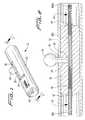
- FIG. 3is an exploded view of the cartridge
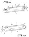
- FIG. 4is a perspective view of the cartridge illustrating the knob being moved from its neutral position in a first direction to expose the engagement member for a femoral delivery approach;
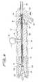
- FIG. 5is a broken perspective view of the introducer sheath and pusher of the delivery system and a perspective view of the cartridge prior to connection to the hub of the sheath wherein the cartridge is shown with the knob in the first extended position to fully expose the engagement member for femoral orientation and connection;
- FIG. 7is a longitudinal cross-sectional view taken along line 7 - 7 of FIG. 6 ;
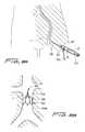
- FIG. 8Billustrates placement of the filter in the inferior vena cava
- FIG. 9is a longitudinal cross-sectional view similar to FIG. 7 except showing the knob moved in a second direction to a second extended position to expose the engagement member from an opposing side of the cartridge for a jugular delivery approach;
- FIGS. 10A and 10Billustrate perspective views of the cartridge showing the position of the knob and engagement member for the jugular approach
- FIG. 11Aillustrates delivery of the filter via the jugular approach
- FIG. 11Billustrates placement of the filter in the inferior vena cava
- FIG. 12Ais a perspective view of one vascular device (a filter) which can be inserted using the cartridge of the present invention
- FIG. 12Bis a perspective view of the filter of FIG. 12A shown in the collapsed position
- FIG. 12Cis a close-up side view of the retention hooks of the filter of FIG. 12B ;
- FIGS. 13 and 14are perspective views of other vascular devices which can be inserted using the cartridge of the present invention.
- a delivery system for delivery and placement of a vascular deviceincludes a cartridge containing the vascular device which is mounted to a component of the delivery system.
- vascular devicescan be contained within the cartridge such as a filter, an aortic valve, replacement valves, etc.
- a vascular filterwill be described and shown throughout the drawings as the vascular device contained in the cartridge, it being understood that other devices can alternatively be contained in the cartridge.
- the cartridge of the present inventionis designed to facilitate the correct orientation of the cartridge so that the filter is delivered to the vessel in the correct orientation. This is achieved not only through the provision of visual indicators on the cartridge but by a sliding mechanism in the cartridge which needs to be moved by the user in order to mount the cartridge to the delivery system component.
- cartridge 10has a housing 12 , a slide 30 slidably received within housing 12 , a tube 40 and a knob 16 .
- Formed within housing 12is an opening 20 , preferably in the form of a slot, which has a longitudinal component 22 , a first radial component 24 and a second radial component 26 .
- Post 18 of knob 16slides within slot 20 as described in more detail below.
- a filter 900corresponding to the filter of FIG. 12 , is shown within tube 40 by way of example. As will become apparent from the discussion below, other filters as well as other vascular devices can be contained in the cartridge 10 .
- Slide 30contains an aperture 39 to receive post 18 of knob 16 .
- Post 18 of knob 16extends slightly into the interior of slide 30 and is rigidly affixed thereto so that the knob 16 can be grasped by the user and moved within slot 20 to thereby move the slide 30 within the housing 12 .
- the knob 16is snap-fit into the aperture 39 .
- Slide 30includes a first engagement member 32 at one end and a second engagement member 34 at the opposite end, each of which provides a snap fit feature.
- slide 30In the initial neutral position of FIGS. 1 and 2 , slide 30 is positioned within housing 10 such that both the first and second engagement members 32 , 34 are contained substantially within the housing 10 . In this position, both engagement members 32 , 34 are in their non-engageable position which corresponds to a retracted position in the illustrated embodiment.
- knob 16is moved in one direction, e.g., the direction of the arrow for a femoral approach, the slide 30 is moved in the same direction to advance the first engagement member 32 from a first non-engageable, e.g.
- the knob 16is moved in the opposite or second direction, e.g., the direction of the arrow for jugular approach, the slide 30 is moved in this second direction to advance the second engagement member 34 from the first non-engageable, e.g. retracted, position in the housing 12 to a second engageable, e.g. extended, position so the second snap fit feature is exposed.
- the radial components of the slot 20function to retain the knob 16 and post 18 in the first or second extended position.
- detent 25helps maintain the knob 16 in the neutral position (corresponding to the retracted position of the engagement members) by requiring overriding a predetermined force to move the knob.
- Other retention structure for the knob 16is also contemplated such as a tapered region.
- the vessel filteris contained in tube 40 .
- This tube 40is positioned in the longitudinal opening extending through slide 30 and is fixedly secured within slide 30 by adhesive so it moves as the slide 30 moves.
- slide 30is insert molded over tube 40 .
- first end portion 42 of tube 40is extended from a first end of housing 12 (see e.g., FIG. 7 ).
- second end portion 44is extended from a second end of housing 12 (see e.g., FIGS. 9 and 10 ).
- the extended tube portions 42 , 44also provide a guide for cartridge connection as they extend into the hub opening (described below).
- a pusher of the delivery systemengages the filter to advance it from the tube 40 along the delivery tube of the delivery system for deployment into the vessel.
- the cartridge 10is mounted to the hub component 102 of the introducer sheath 101 of the delivery system.
- the pusher component of the delivery systemis designated by reference numeral 110 .
- the pusher 110has a pusher tube 112 and a wire 113 which can be made of Nitinol, extending from the pusher tube 112 .
- the wireextends through the cartridge 10 and through the length of delivery tube 106 of introducer sheath 101 to maintain a separation of the retention hooks of the filter during insertion of the delivery system and delivery of the filter through tube 106 .
- a conical tube 119is placed over the free end of tube 40 and snap fitted onto the free engagement member, i.e., the engagement member which is not engaged with the hub, to provide a lead in for the wire 114 .
- the snap-fit engagement of the snap fit feature of the engagement member 32 (or 34 ) of the cartridge 10 within wall 104 of opening 105 of proximal cap 109connects the cartridge 10 to the delivery system, i.e. the introducer sheath 101 .
- Other modes of attachmentare also contemplated.
- FIG. 7illustrates snap-fit feature of engagement member 32 engaged with hub 102 for providing femoral insertion
- FIG. 9illustrates snap-fit feature of engagement member 34 engaged with hub 102 for providing jugular insertion.
- knob 16has been moved from its neutral position to its femoral position
- knob 16has been moved from its neutral position to its jugular position.
- advancement of the pusher 110advances pusher tube (or rod) 112 to advance the filter from the cartridge 10 and through tube 106 as the distal edge 114 of the pusher tube 112 abuts the proximal end of the filter, with the wire 113 preventing entanglement of the retention hooks.
- the wire 113also provides support (stability) for the pusher 110 as the pusher 110 is advanced over the wire.
- Port 107 in hub 102provides an inlet for attachment of a tube for infusion of cold saline as described in more detail below.
- filterscan be utilized with the cartridge of the present invention. These filters are designed for placement within the inferior vena cava to capture blood clots or other particles which could otherwise pass to the lungs.
- the filtersare movable from a low profile collapsed configuration to facilitate insertion through the delivery sheath to a larger expanded placement configuration to engage the vessel walls to secure (mount) the filter within the inferior vena cava.
- FIGS. 12A-12COne example of a filter which can be inserted using the cartridge of the present invention is illustrated in FIGS. 12A-12C .
- This filteris described in detail in pending U.S. patent application Ser. No. 10/889,429, filed Jul. 12, 2004, the entire contents of which are incorporated herein by reference.
- the elongated strutshave a first angled region of interconnecting (connecting) struts 914 a , 914 b in the filtering region 919 and a second angled region of interconnecting (connecting) struts 914 e , 914 f in the mounting region 921 of greater transverse dimension.
- connecting strut portion 914 a of one strut 914interconnects with the connecting strut portion 914 b of an adjacent strut at joining region 914 d .
- Strut portions 914 e , 914 fform connecting portions to connect adjacent strut portions 914 c as connecting strut 914 e of one strut is connected to connecting strut 914 f of an adjacent strut.
- Connecting strut portion 914 e on one strut and portion 914 f of another strutconverge at end (joining) region 929 , as closed geometric shapes 935 are formed.
- the filtering region 919converges at portion 932 into tubular portion 918 .
- the tubular portion 918is preferably in the form of a retrieval hook 950 as described in the '429 application which has a cut out to expose an annular interior surface to accommodate a portion of a tubular snare sheath.
- Strut portions 914 cterminate in hooks 940 a , 940 b which lie in the plane of strut 914 .
- Hooks 940 aare larger than hooks 940 b and smaller hooks 940 b nest within larger hooks and are spaced axially (inwardly) of hooks 940 a as well as spaced axially with respect to each other.
- Filter 900is preferably manufactured from a cut laser tube of shape memory material, such as Nitinol, a nickel titanium alloy, or elgiloy.
- the collapsed configuration of the filterreduces the overall profile to facilitate delivery to the site.
- the diameter or transverse dimension of the filter in the collapsed configurationis preferably about 2 mm and more preferably about 1.7 mm.
- the diameter or transverse dimensions of the filter in the expanded configurationcould range from about 18 mm to about 32 mm, depending on the internal diameter of the vessel.
- cold salineis injected into the delivery tube 106 (or catheter) around the filter in its collapsed position.
- the cold salinemaintains the temperature dependent filter in a relatively softer condition as it is in the martensitic state within tube 106 . This facilitates the exit of the filter from the tube as frictional contact between the filter 10 and the inner surface of the tube would otherwise occur if the filter was maintained in a rigid, i.e. austenitic, condition. Once ejected from tube 106 , the filter is no longer cooled and is exposed to the warmer body temperature, which causes the filter 900 to return towards its austenitic memorized configuration.
- FIGS. 8A and 8Billustrate delivery of the filter 900 , by way of example, in the inferior vena cava “v” via a femoral approach.
- the knob 16 of the cartridge 10is slid in the direction of the femoral arrow to expose the snap fit feature of engagement member 32 (see FIG. 7 ). It is rotated into the radial slot component 24 to maintain it in place.
- the cartridge 10can then be snap fitted onto the hub 102 of introducer sheath 101 .
- the delivery systemis inserted into the femoral vein “f” and advanced through the iliac arteries into the inferior vena cava “v”. Extension 107 of hub 102 receives tubing 350 to enable saline injection.
- the pusher 110is advanced so filter 900 is advanced from cartridge 10 by pusher tube 114 and through tubing 106 of sheath 101 , to a position adjacent tube opening 108 .
- the introducer sheathis then withdrawn so the filter exits through opening 108 exposing the filter to enable filter it to be warmed by body temperature to transition to the expanded placement configuration.
- filter section 919is downstream of the flared anchoring section 921 as shown in FIG. 8B .
- Thisenables blood clots or other particles to be directed to the center of the filter section by the angled struts.
- correct orientation of filter placementcan be appreciated.
- FIG. 11illustrates insertion of filter 900 , by way of example, through the internal jugular vein into the inferior vena cava “v”.
- knob 16is slid along axial slot 20 in the direction of the jugular arrow to expose the snap fit feature of the engagement member 34 (see e.g., FIGS. 9 and 10 ).
- Knob 16is then rotated into the second radial component 26 to retain the snap feature of an engagement member 34 in the extended (exposed) position.
- the snap featureis then connected to the hub 102 of the introducer sheath of the delivery system and the pusher tube 114 of pusher 110 advances the filter through tube 106 of sheath 101 as described above to a position adjacent opening 108 . Withdrawal of sheath 101 exposes the filter to warmer body temperature where it transitions to the expanded configuration.
- filter section 919is downstream of flared anchoring section 921 .
- the filter 900can be removed from access through the internal jugular vein or femoral vein.
- Various methodscan be used to remove the filter such as those described in commonly assigned co-pending application Ser. No. 09/911,097, filed Jul. 23, 2001, now published application 2002-0193827-A1, published Dec. 19, 2001, the entire contents of which is incorporated herein by reference, including, for example, slotted hooks, graspers, etc.
- the recess or cutout in the tubular end portions of filter 900receives a snare or other device for removal.
- Cold salineis injected during the removal process to cool filter 900 to change the temperature to transition to a softer martensitic state to facilitate removal. That is, injection of cold saline will cause the filter to approach its martensitic state, bringing the filter to a more flexible condition.
- the flexible conditionfacilitates the collapse and withdrawal of the filter into the retrieval sheath by decreasing the frictional contact between the filter and the inner surface of the retrieval sheath.
- the cartridge of the present inventioncan also be used for loading other vascular devices which can be delivered through different approaches, e.g. a femoral approach, a jugular approach etc. . . .
- vascular deviceswhich can be delivered through different approaches, e.g. a femoral approach, a jugular approach etc. . . .
- stent grafts, an aortic valve, a replacement valve with vessel wall approximation features, etc.could be positioned within the cartridge and the cartridge connected to a component of a delivery system in the same manner described above to ensure correct orientation and placement of the vascular device.
- FIG. 13illustrates an example of a vascular device which can be contained within the cartridge of the present invention.
- the device 400disclosed in U.S. Pat. No. 6,676,698, the entire contents of which are incorporated herein by reference, has vessel engaging members 451 which approximate the vessel walls and a replacement valve 450 .
- the devicewould be retained in the cartridge in a collapsed configuration and moved to the expanded configuration as shown in FIG. 13 when placed in the vessel.
- Other devices of the '698 patentcould also be contained within the cartridge of the present invention.
- FIG. 14illustrates an example of another vascular device which can be contained within the cartridge of the present invention.
- the devicewould be retained in the cartridge in a collapsed configuration and moved to the expanded configuration of FIG. 14 for vessel placement.
Landscapes
- Health & Medical Sciences (AREA)
- Engineering & Computer Science (AREA)
- Biomedical Technology (AREA)
- Heart & Thoracic Surgery (AREA)
- Life Sciences & Earth Sciences (AREA)
- Cardiology (AREA)
- Oral & Maxillofacial Surgery (AREA)
- Transplantation (AREA)
- Veterinary Medicine (AREA)
- Vascular Medicine (AREA)
- Public Health (AREA)
- Animal Behavior & Ethology (AREA)
- General Health & Medical Sciences (AREA)
- Optics & Photonics (AREA)
- Physics & Mathematics (AREA)
- Surgical Instruments (AREA)
- Prostheses (AREA)
Abstract
Description
Claims (12)
Priority Applications (1)
| Application Number | Priority Date | Filing Date | Title |
|---|---|---|---|
| US11/030,929US7736384B2 (en) | 2005-01-07 | 2005-01-07 | Cartridge for vascular device |
Applications Claiming Priority (1)
| Application Number | Priority Date | Filing Date | Title |
|---|---|---|---|
| US11/030,929US7736384B2 (en) | 2005-01-07 | 2005-01-07 | Cartridge for vascular device |
Publications (2)
| Publication Number | Publication Date |
|---|---|
| US20060155321A1 US20060155321A1 (en) | 2006-07-13 |
| US7736384B2true US7736384B2 (en) | 2010-06-15 |
Family
ID=36654236
Family Applications (1)
| Application Number | Title | Priority Date | Filing Date |
|---|---|---|---|
| US11/030,929Active2027-10-24US7736384B2 (en) | 2005-01-07 | 2005-01-07 | Cartridge for vascular device |
Country Status (1)
| Country | Link |
|---|---|
| US (1) | US7736384B2 (en) |
Cited By (14)
| Publication number | Priority date | Publication date | Assignee | Title |
|---|---|---|---|---|
| US7967838B2 (en) | 2005-05-12 | 2011-06-28 | C. R. Bard, Inc. | Removable embolus blood clot filter |
| US8372109B2 (en) | 2004-08-04 | 2013-02-12 | C. R. Bard, Inc. | Non-entangling vena cava filter |
| US8430903B2 (en) | 2005-08-09 | 2013-04-30 | C. R. Bard, Inc. | Embolus blood clot filter and delivery system |
| US8613754B2 (en) | 2005-05-12 | 2013-12-24 | C. R. Bard, Inc. | Tubular filter |
| US8690906B2 (en) | 1998-09-25 | 2014-04-08 | C.R. Bard, Inc. | Removeable embolus blood clot filter and filter delivery unit |
| US8808350B2 (en) | 2011-03-01 | 2014-08-19 | Endologix, Inc. | Catheter system and methods of using same |
| US9131999B2 (en) | 2005-11-18 | 2015-09-15 | C.R. Bard Inc. | Vena cava filter with filament |
| US9204956B2 (en) | 2002-02-20 | 2015-12-08 | C. R. Bard, Inc. | IVC filter with translating hooks |
| US9326842B2 (en) | 2006-06-05 | 2016-05-03 | C. R . Bard, Inc. | Embolus blood clot filter utilizable with a single delivery system or a single retrieval system in one of a femoral or jugular access |
| US9700701B2 (en) | 2008-07-01 | 2017-07-11 | Endologix, Inc. | Catheter system and methods of using same |
| US10188496B2 (en) | 2006-05-02 | 2019-01-29 | C. R. Bard, Inc. | Vena cava filter formed from a sheet |
| US10485921B2 (en) | 2014-12-17 | 2019-11-26 | Mobile I.V. Systems, LLC | Drip chamber assembly that functions irrespective of orientation |
| US11129737B2 (en) | 2015-06-30 | 2021-09-28 | Endologix Llc | Locking assembly for coupling guidewire to delivery system |
| US12115057B2 (en) | 2005-05-12 | 2024-10-15 | C.R. Bard, Inc. | Tubular filter |
Families Citing this family (20)
| Publication number | Priority date | Publication date | Assignee | Title |
|---|---|---|---|---|
| US20040102789A1 (en)* | 2002-11-22 | 2004-05-27 | Scimed Life Systems, Inc. | Selectively locking device |
| US8317744B2 (en) | 2008-03-27 | 2012-11-27 | St. Jude Medical, Atrial Fibrillation Division, Inc. | Robotic catheter manipulator assembly |
| US8343096B2 (en) | 2008-03-27 | 2013-01-01 | St. Jude Medical, Atrial Fibrillation Division, Inc. | Robotic catheter system |
| US8641663B2 (en)* | 2008-03-27 | 2014-02-04 | St. Jude Medical, Atrial Fibrillation Division, Inc. | Robotic catheter system input device |
| US9161817B2 (en)* | 2008-03-27 | 2015-10-20 | St. Jude Medical, Atrial Fibrillation Division, Inc. | Robotic catheter system |
| US8684962B2 (en)* | 2008-03-27 | 2014-04-01 | St. Jude Medical, Atrial Fibrillation Division, Inc. | Robotic catheter device cartridge |
| US8641664B2 (en)* | 2008-03-27 | 2014-02-04 | St. Jude Medical, Atrial Fibrillation Division, Inc. | Robotic catheter system with dynamic response |
| US9241768B2 (en)* | 2008-03-27 | 2016-01-26 | St. Jude Medical, Atrial Fibrillation Division, Inc. | Intelligent input device controller for a robotic catheter system |
| US8317745B2 (en) | 2008-03-27 | 2012-11-27 | St. Jude Medical, Atrial Fibrillation Division, Inc. | Robotic catheter rotatable device cartridge |
| US20110238010A1 (en)* | 2008-12-31 | 2011-09-29 | Kirschenman Mark B | Robotic catheter system input device |
| US9439736B2 (en) | 2009-07-22 | 2016-09-13 | St. Jude Medical, Atrial Fibrillation Division, Inc. | System and method for controlling a remote medical device guidance system in three-dimensions using gestures |
| US9330497B2 (en) | 2011-08-12 | 2016-05-03 | St. Jude Medical, Atrial Fibrillation Division, Inc. | User interface devices for electrophysiology lab diagnostic and therapeutic equipment |
| FR2950798B1 (en)* | 2009-10-06 | 2012-12-28 | Braun Medical Sas | SAFETY CARTRIDGE FOR A RETIRABLE CELL FILTER |
| US9888973B2 (en) | 2010-03-31 | 2018-02-13 | St. Jude Medical, Atrial Fibrillation Division, Inc. | Intuitive user interface control for remote catheter navigation and 3D mapping and visualization systems |
| CA2808830A1 (en) | 2010-08-23 | 2012-03-01 | Edwards Lifesciences Corporation | Color-coded prosthetic valve system and methods for using the same |
| DE102012022400A1 (en)* | 2012-11-16 | 2014-05-22 | Bentley Innomed Gmbh | Temporary stent |
| WO2016022797A1 (en) | 2014-08-06 | 2016-02-11 | Edwards Lifesciences Corporation | Multi-lumen cannulae |
| EP3743016B1 (en) | 2018-01-23 | 2024-10-02 | Edwards Lifesciences Corporation | Prosthetic valve holders, systems, and methods |
| USD908874S1 (en) | 2018-07-11 | 2021-01-26 | Edwards Lifesciences Corporation | Collapsible heart valve sizer |
| CN112741710B (en)* | 2019-10-31 | 2025-01-21 | 上海微创心通医疗科技有限公司 | A handle for delivering an implant and a delivery system thereof |
Citations (43)
| Publication number | Priority date | Publication date | Assignee | Title |
|---|---|---|---|---|
| US2453901A (en)* | 1944-12-23 | 1948-11-16 | Robert R Gonsett | Compound wrench and screw driver |
| US3744492A (en) | 1971-04-07 | 1973-07-10 | S Leibinsohn | Drip chamber |
| US4266815A (en)* | 1978-07-03 | 1981-05-12 | Smiths Industries Limited | Connectors |
| US4425908A (en) | 1981-10-22 | 1984-01-17 | Beth Israel Hospital | Blood clot filter |
| US5067957A (en) | 1983-10-14 | 1991-11-26 | Raychem Corporation | Method of inserting medical devices incorporating SIM alloy elements |
| US5152777A (en) | 1989-01-25 | 1992-10-06 | Uresil Corporation | Device and method for providing protection from emboli and preventing occulsion of blood vessels |
| US5188616A (en)* | 1990-10-23 | 1993-02-23 | Celsa L.G. (Societe Anomyne) | Syringe with double plunger |
| US5324304A (en) | 1992-06-18 | 1994-06-28 | William Cook Europe A/S | Introduction catheter set for a collapsible self-expandable implant |
| US5479938A (en) | 1994-02-07 | 1996-01-02 | Cordis Corporation | Lumen diameter reference guidewire |
| US5626605A (en) | 1991-12-30 | 1997-05-06 | Scimed Life Systems, Inc. | Thrombosis filter |
| US5681347A (en) | 1995-05-23 | 1997-10-28 | Boston Scientific Corporation | Vena cava filter delivery system |
| US5755790A (en) | 1995-04-14 | 1998-05-26 | B. Braun Celsa | Intraluminal medical device |
| US5836968A (en) | 1996-07-17 | 1998-11-17 | Nitinol Medical Technologies, Inc. | Removable embolus blood clot filter |
| US5895410A (en) | 1997-09-12 | 1999-04-20 | B. Braun Medical, Inc. | Introducer for an expandable vascular occlusion device |
| US6099549A (en) | 1998-07-03 | 2000-08-08 | Cordis Corporation | Vascular filter for controlled release |
| US6165198A (en) | 1994-12-13 | 2000-12-26 | Medtronic, Inc. | Embolic elements and methods and apparatus for their delivery |
| US6168603B1 (en) | 1995-02-02 | 2001-01-02 | Boston Scientific Corporation | Surgical extractor |
| US6231589B1 (en) | 1999-03-22 | 2001-05-15 | Microvena Corporation | Body vessel filter |
| US6328755B1 (en) | 1998-09-24 | 2001-12-11 | Scimed Life Systems, Inc. | Filter delivery device |
| US6331176B1 (en)* | 1999-03-11 | 2001-12-18 | Advanced Cardiovascular Systems, Inc. | Bleed back control assembly and method |
| US6331184B1 (en) | 1999-12-10 | 2001-12-18 | Scimed Life Systems, Inc. | Detachable covering for an implantable medical device |
| US6342062B1 (en) | 1998-09-24 | 2002-01-29 | Scimed Life Systems, Inc. | Retrieval devices for vena cava filter |
| US6447530B1 (en) | 1996-11-27 | 2002-09-10 | Scimed Life Systems, Inc. | Atraumatic anchoring and disengagement mechanism for permanent implant device |
| US6537294B1 (en) | 2000-10-17 | 2003-03-25 | Advanced Cardiovascular Systems, Inc. | Delivery systems for embolic filter devices |
| US6544280B1 (en) | 1999-02-24 | 2003-04-08 | Scimed Life Systems, Inc. | Intravascular filter and method |
| US6569183B1 (en) | 1999-09-03 | 2003-05-27 | Scimed Life Systems, Inc. | Removable thrombus filter |
| US6623506B2 (en) | 2001-06-18 | 2003-09-23 | Rex Medical, L.P | Vein filter |
| US20030195555A1 (en) | 1999-11-08 | 2003-10-16 | Ev3 Sunnyvale, Inc., A California Corporation | Implant retrieval system |
| US6706053B1 (en) | 2000-04-28 | 2004-03-16 | Advanced Cardiovascular Systems, Inc. | Nitinol alloy design for sheath deployable and re-sheathable vascular devices |
| US6712835B2 (en) | 1994-07-08 | 2004-03-30 | Ev3 Inc. | Method and device for filtering body fluid |
| US6783538B2 (en) | 2001-06-18 | 2004-08-31 | Rex Medical, L.P | Removable vein filter |
| US6793665B2 (en) | 2001-06-18 | 2004-09-21 | Rex Medical, L.P. | Multiple access vein filter |
| US6814746B2 (en) | 2002-11-01 | 2004-11-09 | Ev3 Peripheral, Inc. | Implant delivery system with marker interlock |
| US20050004596A1 (en) | 2001-06-18 | 2005-01-06 | Mcguckin James F. | Vein filter |
| US20050015111A1 (en) | 2001-06-18 | 2005-01-20 | Mcguckin James F. | Vein filter |
| US20050165442A1 (en) | 2004-01-22 | 2005-07-28 | Thinnes John H.Jr. | Vein filter |
| US20050209631A1 (en)* | 2004-03-06 | 2005-09-22 | Galdonik Jason A | Steerable device having a corewire within a tube and combination with a functional medical component |
| US6989021B2 (en)* | 2002-10-31 | 2006-01-24 | Cordis Corporation | Retrievable medical filter |
| US6994092B2 (en) | 1999-11-08 | 2006-02-07 | Ev3 Sunnyvale, Inc. | Device for containing embolic material in the LAA having a plurality of tissue retention structures |
| US7037321B2 (en) | 1996-02-23 | 2006-05-02 | Memory Medical Systems, Inc. | Medical device with slotted memory metal tube |
| US7097651B2 (en) | 2001-09-06 | 2006-08-29 | Advanced Cardiovascular Systems, Inc. | Embolic protection basket |
| US7316708B2 (en) | 2002-12-05 | 2008-01-08 | Cardiac Dimensions, Inc. | Medical device delivery system |
| US7338512B2 (en) | 2004-01-22 | 2008-03-04 | Rex Medical, L.P. | Vein filter |
Family Cites Families (3)
| Publication number | Priority date | Publication date | Assignee | Title |
|---|---|---|---|---|
| US195555A (en)* | 1877-09-25 | Improvement in spoke-polishing machines | ||
| US4596A (en)* | 1846-06-27 | Tailor s measure | ||
| US15111A (en)* | 1856-06-10 | Japanning- pins |
- 2005
- 2005-01-07USUS11/030,929patent/US7736384B2/enactiveActive
Patent Citations (45)
| Publication number | Priority date | Publication date | Assignee | Title |
|---|---|---|---|---|
| US2453901A (en)* | 1944-12-23 | 1948-11-16 | Robert R Gonsett | Compound wrench and screw driver |
| US3744492A (en) | 1971-04-07 | 1973-07-10 | S Leibinsohn | Drip chamber |
| US4266815A (en)* | 1978-07-03 | 1981-05-12 | Smiths Industries Limited | Connectors |
| US4425908A (en) | 1981-10-22 | 1984-01-17 | Beth Israel Hospital | Blood clot filter |
| US5067957A (en) | 1983-10-14 | 1991-11-26 | Raychem Corporation | Method of inserting medical devices incorporating SIM alloy elements |
| US5152777A (en) | 1989-01-25 | 1992-10-06 | Uresil Corporation | Device and method for providing protection from emboli and preventing occulsion of blood vessels |
| US5188616A (en)* | 1990-10-23 | 1993-02-23 | Celsa L.G. (Societe Anomyne) | Syringe with double plunger |
| US5626605A (en) | 1991-12-30 | 1997-05-06 | Scimed Life Systems, Inc. | Thrombosis filter |
| US5324304A (en) | 1992-06-18 | 1994-06-28 | William Cook Europe A/S | Introduction catheter set for a collapsible self-expandable implant |
| US5479938A (en) | 1994-02-07 | 1996-01-02 | Cordis Corporation | Lumen diameter reference guidewire |
| US6712835B2 (en) | 1994-07-08 | 2004-03-30 | Ev3 Inc. | Method and device for filtering body fluid |
| US6165198A (en) | 1994-12-13 | 2000-12-26 | Medtronic, Inc. | Embolic elements and methods and apparatus for their delivery |
| US6168603B1 (en) | 1995-02-02 | 2001-01-02 | Boston Scientific Corporation | Surgical extractor |
| US5755790A (en) | 1995-04-14 | 1998-05-26 | B. Braun Celsa | Intraluminal medical device |
| US6165179A (en) | 1995-05-23 | 2000-12-26 | Boston Scientific Corporation | Vena cava delivery system |
| US5681347A (en) | 1995-05-23 | 1997-10-28 | Boston Scientific Corporation | Vena cava filter delivery system |
| US7037321B2 (en) | 1996-02-23 | 2006-05-02 | Memory Medical Systems, Inc. | Medical device with slotted memory metal tube |
| US5836968A (en) | 1996-07-17 | 1998-11-17 | Nitinol Medical Technologies, Inc. | Removable embolus blood clot filter |
| US6447530B1 (en) | 1996-11-27 | 2002-09-10 | Scimed Life Systems, Inc. | Atraumatic anchoring and disengagement mechanism for permanent implant device |
| US5895410A (en) | 1997-09-12 | 1999-04-20 | B. Braun Medical, Inc. | Introducer for an expandable vascular occlusion device |
| US6099549A (en) | 1998-07-03 | 2000-08-08 | Cordis Corporation | Vascular filter for controlled release |
| US6342062B1 (en) | 1998-09-24 | 2002-01-29 | Scimed Life Systems, Inc. | Retrieval devices for vena cava filter |
| US6328755B1 (en) | 1998-09-24 | 2001-12-11 | Scimed Life Systems, Inc. | Filter delivery device |
| US6726621B2 (en) | 1998-09-24 | 2004-04-27 | Scimed Life Systems, Inc. | Retrieval devices for vena cava filter |
| US6544280B1 (en) | 1999-02-24 | 2003-04-08 | Scimed Life Systems, Inc. | Intravascular filter and method |
| US6331176B1 (en)* | 1999-03-11 | 2001-12-18 | Advanced Cardiovascular Systems, Inc. | Bleed back control assembly and method |
| US6231589B1 (en) | 1999-03-22 | 2001-05-15 | Microvena Corporation | Body vessel filter |
| US6569183B1 (en) | 1999-09-03 | 2003-05-27 | Scimed Life Systems, Inc. | Removable thrombus filter |
| US6994092B2 (en) | 1999-11-08 | 2006-02-07 | Ev3 Sunnyvale, Inc. | Device for containing embolic material in the LAA having a plurality of tissue retention structures |
| US20030195555A1 (en) | 1999-11-08 | 2003-10-16 | Ev3 Sunnyvale, Inc., A California Corporation | Implant retrieval system |
| US6331184B1 (en) | 1999-12-10 | 2001-12-18 | Scimed Life Systems, Inc. | Detachable covering for an implantable medical device |
| US6706053B1 (en) | 2000-04-28 | 2004-03-16 | Advanced Cardiovascular Systems, Inc. | Nitinol alloy design for sheath deployable and re-sheathable vascular devices |
| US6537294B1 (en) | 2000-10-17 | 2003-03-25 | Advanced Cardiovascular Systems, Inc. | Delivery systems for embolic filter devices |
| US6783538B2 (en) | 2001-06-18 | 2004-08-31 | Rex Medical, L.P | Removable vein filter |
| US20050004596A1 (en) | 2001-06-18 | 2005-01-06 | Mcguckin James F. | Vein filter |
| US20050015111A1 (en) | 2001-06-18 | 2005-01-20 | Mcguckin James F. | Vein filter |
| US6793665B2 (en) | 2001-06-18 | 2004-09-21 | Rex Medical, L.P. | Multiple access vein filter |
| US6623506B2 (en) | 2001-06-18 | 2003-09-23 | Rex Medical, L.P | Vein filter |
| US7097651B2 (en) | 2001-09-06 | 2006-08-29 | Advanced Cardiovascular Systems, Inc. | Embolic protection basket |
| US6989021B2 (en)* | 2002-10-31 | 2006-01-24 | Cordis Corporation | Retrievable medical filter |
| US6814746B2 (en) | 2002-11-01 | 2004-11-09 | Ev3 Peripheral, Inc. | Implant delivery system with marker interlock |
| US7316708B2 (en) | 2002-12-05 | 2008-01-08 | Cardiac Dimensions, Inc. | Medical device delivery system |
| US20050165442A1 (en) | 2004-01-22 | 2005-07-28 | Thinnes John H.Jr. | Vein filter |
| US7338512B2 (en) | 2004-01-22 | 2008-03-04 | Rex Medical, L.P. | Vein filter |
| US20050209631A1 (en)* | 2004-03-06 | 2005-09-22 | Galdonik Jason A | Steerable device having a corewire within a tube and combination with a functional medical component |
Non-Patent Citations (10)
| Title |
|---|
| Caval Interruption Methods; Comparison of Options, by Thomas A. Whitehill, Seminars in Vascular Surgery, vol. 9, No. 1 (Mar. 1996), pp. 59-69. |
| Cordis Endovascular, Instruction for Use, Cordis TRAPEASE(TM) Permanent Vena Cava Filter and Introduction Kit, Jun. 2001. |
| Cordis Endovascular, Instruction for Use, Cordis TRAPEASE™ Permanent Vena Cava Filter and Introduction Kit, Jun. 2001. |
| Instructions for Use, Cordis OPTEASE Permanent Vena Cava Filter,-Cordis Johnson & Johnson Company. |
| Instructions for Use, Cordis OPTEASE Permanent Vena Cava Filter,—Cordis Johnson & Johnson Company. |
| Instructions for Use, Recovery Filter System for Use in Vena Cava-C. R.Bard 2003. |
| Instructions for Use, Recovery Filter System for Use in Vena Cava—C. R.Bard 2003. |
| LGM (Vena Tech) Vena Cava Filter: Clinical Experience in 64 Patients, Millward, et al, JVIR vol. 2, No. 4, Nov. 1991, pp. 429-433. |
| Vena Tech LP Vena Cava Filter, B. Braun Medical Inc., 2001. |
| Vena Tech LP, Femoral Approach, B. Braun Medical Inc., 2001. |
Cited By (40)
| Publication number | Priority date | Publication date | Assignee | Title |
|---|---|---|---|---|
| US9615909B2 (en) | 1998-09-25 | 2017-04-11 | C.R. Bard, Inc. | Removable embolus blood clot filter and filter delivery unit |
| US9351821B2 (en) | 1998-09-25 | 2016-05-31 | C. R. Bard, Inc. | Removable embolus blood clot filter and filter delivery unit |
| US8690906B2 (en) | 1998-09-25 | 2014-04-08 | C.R. Bard, Inc. | Removeable embolus blood clot filter and filter delivery unit |
| US9204956B2 (en) | 2002-02-20 | 2015-12-08 | C. R. Bard, Inc. | IVC filter with translating hooks |
| US9144484B2 (en) | 2004-08-04 | 2015-09-29 | C. R. Bard, Inc. | Non-entangling vena cava filter |
| US8372109B2 (en) | 2004-08-04 | 2013-02-12 | C. R. Bard, Inc. | Non-entangling vena cava filter |
| US11103339B2 (en) | 2004-08-04 | 2021-08-31 | C. R. Bard, Inc. | Non-entangling vena cava filter |
| US8628556B2 (en) | 2004-08-04 | 2014-01-14 | C. R. Bard, Inc. | Non-entangling vena cava filter |
| US12115057B2 (en) | 2005-05-12 | 2024-10-15 | C.R. Bard, Inc. | Tubular filter |
| US8574261B2 (en) | 2005-05-12 | 2013-11-05 | C. R. Bard, Inc. | Removable embolus blood clot filter |
| US9017367B2 (en) | 2005-05-12 | 2015-04-28 | C. R. Bard, Inc. | Tubular filter |
| US10813738B2 (en) | 2005-05-12 | 2020-10-27 | C.R. Bard, Inc. | Tubular filter |
| US10729527B2 (en) | 2005-05-12 | 2020-08-04 | C.R. Bard, Inc. | Removable embolus blood clot filter |
| US8613754B2 (en) | 2005-05-12 | 2013-12-24 | C. R. Bard, Inc. | Tubular filter |
| US7967838B2 (en) | 2005-05-12 | 2011-06-28 | C. R. Bard, Inc. | Removable embolus blood clot filter |
| US9498318B2 (en) | 2005-05-12 | 2016-11-22 | C.R. Bard, Inc. | Removable embolus blood clot filter |
| US11730583B2 (en) | 2005-05-12 | 2023-08-22 | C.R. Band. Inc. | Tubular filter |
| US11554006B2 (en) | 2005-05-12 | 2023-01-17 | C. R. Bard Inc. | Removable embolus blood clot filter |
| US11517415B2 (en) | 2005-08-09 | 2022-12-06 | C.R. Bard, Inc. | Embolus blood clot filter and delivery system |
| US9387063B2 (en) | 2005-08-09 | 2016-07-12 | C. R. Bard, Inc. | Embolus blood clot filter and delivery system |
| US8430903B2 (en) | 2005-08-09 | 2013-04-30 | C. R. Bard, Inc. | Embolus blood clot filter and delivery system |
| US10492898B2 (en) | 2005-08-09 | 2019-12-03 | C.R. Bard, Inc. | Embolus blood clot filter and delivery system |
| US9131999B2 (en) | 2005-11-18 | 2015-09-15 | C.R. Bard Inc. | Vena cava filter with filament |
| US10842608B2 (en) | 2005-11-18 | 2020-11-24 | C.R. Bard, Inc. | Vena cava filter with filament |
| US12226302B2 (en) | 2005-11-18 | 2025-02-18 | C.R. Bard, Inc. | Vena cava filter with filament |
| US10188496B2 (en) | 2006-05-02 | 2019-01-29 | C. R. Bard, Inc. | Vena cava filter formed from a sheet |
| US10980626B2 (en) | 2006-05-02 | 2021-04-20 | C. R. Bard, Inc. | Vena cava filter formed from a sheet |
| US11141257B2 (en) | 2006-06-05 | 2021-10-12 | C. R. Bard, Inc. | Embolus blood clot filter utilizable with a single delivery system or a single retrieval system in one of a femoral or jugular access |
| US9326842B2 (en) | 2006-06-05 | 2016-05-03 | C. R . Bard, Inc. | Embolus blood clot filter utilizable with a single delivery system or a single retrieval system in one of a femoral or jugular access |
| US10512758B2 (en) | 2008-07-01 | 2019-12-24 | Endologix, Inc. | Catheter system and methods of using same |
| US9700701B2 (en) | 2008-07-01 | 2017-07-11 | Endologix, Inc. | Catheter system and methods of using same |
| US9549835B2 (en) | 2011-03-01 | 2017-01-24 | Endologix, Inc. | Catheter system and methods of using same |
| US9687374B2 (en) | 2011-03-01 | 2017-06-27 | Endologix, Inc. | Catheter system and methods of using same |
| US10660775B2 (en) | 2011-03-01 | 2020-05-26 | Endologix, Inc. | Catheter system and methods of using same |
| US8808350B2 (en) | 2011-03-01 | 2014-08-19 | Endologix, Inc. | Catheter system and methods of using same |
| US12239558B2 (en) | 2011-03-01 | 2025-03-04 | Endologix Llc | Catheter system and methods of using same |
| US11541165B2 (en) | 2014-12-17 | 2023-01-03 | Mobile I.S. Systems, Llc | Drip chamber assembly that functions irrespective of orientation |
| US10485921B2 (en) | 2014-12-17 | 2019-11-26 | Mobile I.V. Systems, LLC | Drip chamber assembly that functions irrespective of orientation |
| US11129737B2 (en) | 2015-06-30 | 2021-09-28 | Endologix Llc | Locking assembly for coupling guidewire to delivery system |
| US12186215B2 (en) | 2015-06-30 | 2025-01-07 | Endologix Llc | Locking assembly for coupling guidewire to delivery system |
Also Published As
| Publication number | Publication date |
|---|---|
| US20060155321A1 (en) | 2006-07-13 |
Similar Documents
| Publication | Publication Date | Title |
|---|---|---|
| US7736384B2 (en) | Cartridge for vascular device | |
| US7736383B2 (en) | Vein filter cartridge | |
| US10898311B2 (en) | Embolus blood clot filter delivery system | |
| US4425908A (en) | Blood clot filter | |
| US9107733B2 (en) | Removable blood conduit filter | |
| US9387062B2 (en) | Intravenous deep vein thrombosis filter and method of filter placement | |
| US10299797B2 (en) | Occlusion device and methods of using the same | |
| US7976562B2 (en) | Method of removing a vein filter | |
| US7147649B2 (en) | Temporary vascular filters | |
| US7704266B2 (en) | Vein filter | |
| EP1046375B1 (en) | Occlusion device | |
| US7338512B2 (en) | Vein filter | |
| CA2455349C (en) | Vein filter | |
| US20080294188A1 (en) | Implant Holder and Method of Deploying the Implant | |
| US20050080447A1 (en) | Multiple access vein filter | |
| JPH02131756A (en) | Filter for medical treatment | |
| US11389283B2 (en) | Filter and occluder systems and associated methods and devices | |
| US10159556B2 (en) | Method of inserting a vein filter | |
| US20140236213A1 (en) | Temporary filter retrieval apparatus and method | |
| US8702747B2 (en) | Femoral removal vena cava filter |
Legal Events
| Date | Code | Title | Description |
|---|---|---|---|
| AS | Assignment | Owner name:REX MEDICAL, L.P., PENNSYLVANIA Free format text:ASSIGNMENT OF ASSIGNORS INTEREST;ASSIGNORS:BRESSLER, JAMES ERICH;BRIGANTI, RICHARD T.;THINNES, JOHN T., JR.;AND OTHERS;REEL/FRAME:016462/0546;SIGNING DATES FROM 20050314 TO 20050321 Owner name:REX MEDICAL, L.P.,PENNSYLVANIA Free format text:ASSIGNMENT OF ASSIGNORS INTEREST;ASSIGNORS:BRESSLER, JAMES ERICH;BRIGANTI, RICHARD T.;THINNES, JOHN T., JR.;AND OTHERS;SIGNING DATES FROM 20050314 TO 20050321;REEL/FRAME:016462/0546 | |
| STCF | Information on status: patent grant | Free format text:PATENTED CASE | |
| FPAY | Fee payment | Year of fee payment:4 | |
| AS | Assignment | Owner name:ARGON MEDICAL DEVICES, INC., TEXAS Free format text:ASSIGNMENT OF ASSIGNORS INTEREST;ASSIGNOR:REX MEDICAL, L.P.;REEL/FRAME:037472/0151 Effective date:20151223 | |
| AS | Assignment | Owner name:HEALTHCARE FINANCIAL SOLUTIONS, LLC, AS ADMINISTRA Free format text:FIRST LIEN PATENT SECURITY AGREEMENT;ASSIGNOR:ARGON MEDICAL DEVICES, INC.;REEL/FRAME:037703/0001 Effective date:20151223 | |
| AS | Assignment | Owner name:HEALTHCARE FINANCIAL SOLUTIONS, LLC, AS ADMINISTRA Free format text:SECOND LIEN PATENT SECURITY AGREEMENT;ASSIGNOR:ARGON MEDICAL DEVICES, INC.;REEL/FRAME:037827/0460 Effective date:20151223 | |
| MAFP | Maintenance fee payment | Free format text:PAYMENT OF MAINTENANCE FEE, 8TH YEAR, LARGE ENTITY (ORIGINAL EVENT CODE: M1552) Year of fee payment:8 | |
| AS | Assignment | Owner name:ARGON MEDICAL DEVICES, INC., ILLINOIS Free format text:RELEASE OF FIRST LIEN PATENT SECURITY AGREEMENTS RECORDED AT REEL/FRAME 037703/0001, 037702/0592, 037702/0580, AND 037702/0497;ASSIGNOR:HEALTHCARE FINANCIAL SOLUTIONS, LLC, AS ADMINISTRATIVE AGENT;REEL/FRAME:045130/0706 Effective date:20180123 Owner name:PROMEX TECHNOLOGIES, LLC, ILLINOIS Free format text:RELEASE OF FIRST LIEN PATENT SECURITY AGREEMENTS RECORDED AT REEL/FRAME 037703/0001, 037702/0592, 037702/0580, AND 037702/0497;ASSIGNOR:HEALTHCARE FINANCIAL SOLUTIONS, LLC, AS ADMINISTRATIVE AGENT;REEL/FRAME:045130/0706 Effective date:20180123 Owner name:MEDICAL DEVICE TECHNOLOGIES, INC., ILLINOIS Free format text:RELEASE OF FIRST LIEN PATENT SECURITY AGREEMENTS RECORDED AT REEL/FRAME 037703/0001, 037702/0592, 037702/0580, AND 037702/0497;ASSIGNOR:HEALTHCARE FINANCIAL SOLUTIONS, LLC, AS ADMINISTRATIVE AGENT;REEL/FRAME:045130/0706 Effective date:20180123 Owner name:MANAN MEDICAL PRODUCTS, INC., ILLINOIS Free format text:RELEASE OF FIRST LIEN PATENT SECURITY AGREEMENTS RECORDED AT REEL/FRAME 037703/0001, 037702/0592, 037702/0580, AND 037702/0497;ASSIGNOR:HEALTHCARE FINANCIAL SOLUTIONS, LLC, AS ADMINISTRATIVE AGENT;REEL/FRAME:045130/0525 Effective date:20180123 Owner name:LUTHER MEDICAL PRODUCTS, INC., ILLINOIS Free format text:RELEASE OF FIRST LIEN PATENT SECURITY AGREEMENTS RECORDED AT REEL/FRAME 037703/0001, 037702/0592, 037702/0580, AND 037702/0497;ASSIGNOR:HEALTHCARE FINANCIAL SOLUTIONS, LLC, AS ADMINISTRATIVE AGENT;REEL/FRAME:045130/0706 Effective date:20180123 Owner name:MEDICAL DEVICE TECHNOLOGIES, INC., ILLINOIS Free format text:RELEASE OF FIRST LIEN PATENT SECURITY AGREEMENTS RECORDED AT REEL/FRAME 037703/0001, 037702/0592, 037702/0580, AND 037702/0497;ASSIGNOR:HEALTHCARE FINANCIAL SOLUTIONS, LLC, AS ADMINISTRATIVE AGENT;REEL/FRAME:045130/0525 Effective date:20180123 Owner name:MANAN MEDICAL PRODUCTS, INC., ILLINOIS Free format text:RELEASE OF FIRST LIEN PATENT SECURITY AGREEMENTS RECORDED AT REEL/FRAME 037703/0001, 037702/0592, 037702/0580, AND 037702/0497;ASSIGNOR:HEALTHCARE FINANCIAL SOLUTIONS, LLC, AS ADMINISTRATIVE AGENT;REEL/FRAME:045130/0706 Effective date:20180123 Owner name:PROMEX TECHNOLOGIES, LLC, ILLINOIS Free format text:RELEASE OF FIRST LIEN PATENT SECURITY AGREEMENTS RECORDED AT REEL/FRAME 037703/0001, 037702/0592, 037702/0580, AND 037702/0497;ASSIGNOR:HEALTHCARE FINANCIAL SOLUTIONS, LLC, AS ADMINISTRATIVE AGENT;REEL/FRAME:045130/0525 Effective date:20180123 Owner name:ARGON MEDICAL DEVICES, INC., ILLINOIS Free format text:RELEASE OF FIRST LIEN PATENT SECURITY AGREEMENTS RECORDED AT REEL/FRAME 037703/0001, 037702/0592, 037702/0580, AND 037702/0497;ASSIGNOR:HEALTHCARE FINANCIAL SOLUTIONS, LLC, AS ADMINISTRATIVE AGENT;REEL/FRAME:045130/0525 Effective date:20180123 Owner name:MEDICAL DEVICE TECHNOLOGIES, INC., ILLINOIS Free format text:RELEASE OF SECOND LIEN PATENT SECURITY AGREEMENTS RECORDED AT REEL/FRAME 037827/0460, 037827/0526, 037827/0764, AND 037827/0882;ASSIGNOR:HEALTHCARE FINANCIAL SOLUTIONS, LLC, AS ADMINISTRATIVE AGENT;REEL/FRAME:045130/0906 Effective date:20180123 Owner name:LUTHER MEDICAL PRODUCTS, INC., ILLINOIS Free format text:RELEASE OF SECOND LIEN PATENT SECURITY AGREEMENTS RECORDED AT REEL/FRAME 037827/0460, 037827/0526, 037827/0764, AND 037827/0882;ASSIGNOR:HEALTHCARE FINANCIAL SOLUTIONS, LLC, AS ADMINISTRATIVE AGENT;REEL/FRAME:045130/0906 Effective date:20180123 Owner name:MANAN MEDICAL PRODUCTS, INC., ILLINOIS Free format text:RELEASE OF SECOND LIEN PATENT SECURITY AGREEMENTS RECORDED AT REEL/FRAME 037827/0460, 037827/0526, 037827/0764, AND 037827/0882;ASSIGNOR:HEALTHCARE FINANCIAL SOLUTIONS, LLC, AS ADMINISTRATIVE AGENT;REEL/FRAME:045130/0906 Effective date:20180123 Owner name:PROMEX TECHNOLOGIES, LLC, ILLINOIS Free format text:RELEASE OF SECOND LIEN PATENT SECURITY AGREEMENTS RECORDED AT REEL/FRAME 037827/0460, 037827/0526, 037827/0764, AND 037827/0882;ASSIGNOR:HEALTHCARE FINANCIAL SOLUTIONS, LLC, AS ADMINISTRATIVE AGENT;REEL/FRAME:045130/0906 Effective date:20180123 Owner name:ARGON MEDICAL DEVICES, INC., ILLINOIS Free format text:RELEASE OF SECOND LIEN PATENT SECURITY AGREEMENTS RECORDED AT REEL/FRAME 037827/0460, 037827/0526, 037827/0764, AND 037827/0882;ASSIGNOR:HEALTHCARE FINANCIAL SOLUTIONS, LLC, AS ADMINISTRATIVE AGENT;REEL/FRAME:045130/0906 Effective date:20180123 | |
| AS | Assignment | Owner name:UBS AG, STAMFORD BRANCH, AS COLLATERAL AGENT, CONNECTICUT Free format text:SECOND LIEN PATENT SECURITY AGREEMENT;ASSIGNORS:ARGON MEDICAL DEVICES, INC.;MEDICAL DEVICE TECHNOLOGIES, INC.;MANAN MEDICAL PRODUCTS, INC.;REEL/FRAME:046127/0602 Effective date:20180123 Owner name:UBS AG, STAMFORD BRANCH, AS COLLATERAL AGENT, CONNECTICUT Free format text:FIRST LIEN PATENT SECURITY AGREEMENT;ASSIGNORS:ARGON MEDICAL DEVICES, INC.;MEDICAL DEVICE TECHNOLOGIES, INC.;MANAN MEDICAL PRODUCTS, INC.;REEL/FRAME:046127/0748 Effective date:20180123 Owner name:UBS AG, STAMFORD BRANCH, AS COLLATERAL AGENT, CONN Free format text:SECOND LIEN PATENT SECURITY AGREEMENT;ASSIGNORS:ARGON MEDICAL DEVICES, INC.;MEDICAL DEVICE TECHNOLOGIES, INC.;MANAN MEDICAL PRODUCTS, INC.;REEL/FRAME:046127/0602 Effective date:20180123 Owner name:UBS AG, STAMFORD BRANCH, AS COLLATERAL AGENT, CONN Free format text:FIRST LIEN PATENT SECURITY AGREEMENT;ASSIGNORS:ARGON MEDICAL DEVICES, INC.;MEDICAL DEVICE TECHNOLOGIES, INC.;MANAN MEDICAL PRODUCTS, INC.;REEL/FRAME:046127/0748 Effective date:20180123 | |
| AS | Assignment | Owner name:MANAN MEDICAL PRODUCTS, INC., ILLINOIS Free format text:TERMINATION AND RELEASE OF SECOND LIEN SECURITY INTEREST IN PATENTS;ASSIGNOR:UBS AG, STAMFORD BRANCH, AS COLLATERAL AGENT;REEL/FRAME:050375/0620 Effective date:20190912 Owner name:MEDICAL DEVICE TECHNOLOGIES, INC., ILLINOIS Free format text:TERMINATION AND RELEASE OF FIRST LIEN SECURITY INTEREST IN PATENTS;ASSIGNOR:UBS AG, STAMFORD BRANCH, AS COLLATERAL AGENT;REEL/FRAME:050375/0599 Effective date:20190912 Owner name:MEDICAL DEVICE TECHNOLOGIES, INC., ILLINOIS Free format text:TERMINATION AND RELEASE OF SECOND LIEN SECURITY INTEREST IN PATENTS;ASSIGNOR:UBS AG, STAMFORD BRANCH, AS COLLATERAL AGENT;REEL/FRAME:050375/0620 Effective date:20190912 Owner name:ARGON MEDICAL DEVICES, INC., ILLINOIS Free format text:TERMINATION AND RELEASE OF SECOND LIEN SECURITY INTEREST IN PATENTS;ASSIGNOR:UBS AG, STAMFORD BRANCH, AS COLLATERAL AGENT;REEL/FRAME:050375/0620 Effective date:20190912 Owner name:ARGON MEDICAL DEVICES, INC., ILLINOIS Free format text:TERMINATION AND RELEASE OF FIRST LIEN SECURITY INTEREST IN PATENTS;ASSIGNOR:UBS AG, STAMFORD BRANCH, AS COLLATERAL AGENT;REEL/FRAME:050375/0599 Effective date:20190912 Owner name:MANAN MEDICAL PRODUCTS, INC., ILLINOIS Free format text:TERMINATION AND RELEASE OF FIRST LIEN SECURITY INTEREST IN PATENTS;ASSIGNOR:UBS AG, STAMFORD BRANCH, AS COLLATERAL AGENT;REEL/FRAME:050375/0599 Effective date:20190912 | |
| MAFP | Maintenance fee payment | Free format text:PAYMENT OF MAINTENANCE FEE, 12TH YEAR, LARGE ENTITY (ORIGINAL EVENT CODE: M1553); ENTITY STATUS OF PATENT OWNER: LARGE ENTITY Year of fee payment:12 | |
| AS | Assignment | Owner name:ARGON MEDICAL DEVICES, INC., TEXAS Free format text:CHANGE OF OWNER/ASSIGNEE ADDRESS;ASSIGNOR:ARGON MEDICAL DEVICES, INC.;REEL/FRAME:062437/0600 Effective date:20230119 | |
| AS | Assignment | Owner name:HSBC BANK USA, NATIONAL ASSOCIATION, AS COLLATERAL AGENT, NEW YORK Free format text:SECURITY INTEREST;ASSIGNORS:ARGON MEDICAL DEVICES, INC.;MEDICAL DEVICE TECHNOLOGIES, INC.;MANAN MEDICAL PRODUCTS, INC.;REEL/FRAME:065612/0206 Effective date:20190912 | |
| AS | Assignment | Owner name:HSBC BANK USA, NATIONAL ASSOCIATION, AS COLLATERAL AGENT, NEW YORK Free format text:SECURITY INTEREST;ASSIGNORS:ARGON MEDICAL DEVICES, INC.;MEDICAL DEVICE TECHNOLOGIES, INC.;MANAN MEDICAL PRODUCTS, INC.;REEL/FRAME:066816/0020 Effective date:20240318 | |
| AS | Assignment | Owner name:MANAN MEDICAL PRODUCTS, INC., TEXAS Free format text:RELEASE BY SECURED PARTY;ASSIGNOR:HSBC BANK USA, NATIONAL ASSOCIATION, AS COLLATERAL AGENT;REEL/FRAME:066883/0812 Effective date:20240318 Owner name:MEDICAL DEVICE TECHNOLOGIES, INC., TEXAS Free format text:RELEASE BY SECURED PARTY;ASSIGNOR:HSBC BANK USA, NATIONAL ASSOCIATION, AS COLLATERAL AGENT;REEL/FRAME:066883/0812 Effective date:20240318 Owner name:ARGON MEDICAL DEVICES, INC., TEXAS Free format text:RELEASE BY SECURED PARTY;ASSIGNOR:HSBC BANK USA, NATIONAL ASSOCIATION, AS COLLATERAL AGENT;REEL/FRAME:066883/0812 Effective date:20240318 |