US7736322B2 - Precision depth control lancing tip - Google Patents
Precision depth control lancing tipDownload PDFInfo
- Publication number
- US7736322B2 US7736322B2US10/744,167US74416703AUS7736322B2US 7736322 B2US7736322 B2US 7736322B2US 74416703 AUS74416703 AUS 74416703AUS 7736322 B2US7736322 B2US 7736322B2
- Authority
- US
- United States
- Prior art keywords
- lancet
- opening
- expression
- skin
- incision
- Prior art date
- Legal status (The legal status is an assumption and is not a legal conclusion. Google has not performed a legal analysis and makes no representation as to the accuracy of the status listed.)
- Expired - Fee Related, expires
Links
- 238000005070samplingMethods0.000claimsabstractdescription149
- 239000012530fluidSubstances0.000claimsabstractdescription146
- 230000035515penetrationEffects0.000claimsabstractdescription81
- 238000000034methodMethods0.000claimsdescription34
- 238000003825pressingMethods0.000claimsdescription19
- 210000001124body fluidAnatomy0.000abstractdescription61
- 238000012360testing methodMethods0.000description85
- 230000007246mechanismEffects0.000description41
- 210000003128headAnatomy0.000description24
- 239000010839body fluidSubstances0.000description22
- 239000008280bloodSubstances0.000description15
- 210000004369bloodAnatomy0.000description15
- 230000008859changeEffects0.000description14
- WQZGKKKJIJFFOK-GASJEMHNSA-NGlucoseNatural productsOC[C@H]1OC(O)[C@H](O)[C@@H](O)[C@@H]1OWQZGKKKJIJFFOK-GASJEMHNSA-N0.000description10
- 239000008103glucoseSubstances0.000description10
- 239000012491analyteSubstances0.000description9
- 230000037452primingEffects0.000description8
- 239000000463materialSubstances0.000description7
- 230000001954sterilising effectEffects0.000description7
- 238000004659sterilization and disinfectionMethods0.000description7
- 239000003153chemical reaction reagentSubstances0.000description5
- 210000000245forearmAnatomy0.000description5
- 239000012528membraneSubstances0.000description5
- 230000009471actionEffects0.000description4
- 230000008901benefitEffects0.000description4
- 230000036512infertilityEffects0.000description4
- 229920003023plasticPolymers0.000description4
- 239000004033plasticSubstances0.000description4
- 208000002193PainDiseases0.000description3
- 238000004458analytical methodMethods0.000description3
- 239000011324beadSubstances0.000description3
- 210000000624ear auricleAnatomy0.000description3
- 210000003722extracellular fluidAnatomy0.000description3
- 230000003287optical effectEffects0.000description3
- 230000008569processEffects0.000description3
- XEEYBQQBJWHFJM-UHFFFAOYSA-NIronChemical compound[Fe]XEEYBQQBJWHFJM-UHFFFAOYSA-N0.000description2
- 208000027418Wounds and injuryDiseases0.000description2
- 230000015572biosynthetic processEffects0.000description2
- 238000010241blood samplingMethods0.000description2
- 230000006378damageEffects0.000description2
- 230000007423decreaseEffects0.000description2
- 238000013461designMethods0.000description2
- 238000010304firingMethods0.000description2
- 208000014674injuryDiseases0.000description2
- NOESYZHRGYRDHS-UHFFFAOYSA-NinsulinChemical compoundN1C(=O)C(NC(=O)C(CCC(N)=O)NC(=O)C(CCC(O)=O)NC(=O)C(C(C)C)NC(=O)C(NC(=O)CN)C(C)CC)CSSCC(C(NC(CO)C(=O)NC(CC(C)C)C(=O)NC(CC=2C=CC(O)=CC=2)C(=O)NC(CCC(N)=O)C(=O)NC(CC(C)C)C(=O)NC(CCC(O)=O)C(=O)NC(CC(N)=O)C(=O)NC(CC=2C=CC(O)=CC=2)C(=O)NC(CSSCC(NC(=O)C(C(C)C)NC(=O)C(CC(C)C)NC(=O)C(CC=2C=CC(O)=CC=2)NC(=O)C(CC(C)C)NC(=O)C(C)NC(=O)C(CCC(O)=O)NC(=O)C(C(C)C)NC(=O)C(CC(C)C)NC(=O)C(CC=2NC=NC=2)NC(=O)C(CO)NC(=O)CNC2=O)C(=O)NCC(=O)NC(CCC(O)=O)C(=O)NC(CCCNC(N)=N)C(=O)NCC(=O)NC(CC=3C=CC=CC=3)C(=O)NC(CC=3C=CC=CC=3)C(=O)NC(CC=3C=CC(O)=CC=3)C(=O)NC(C(C)O)C(=O)N3C(CCC3)C(=O)NC(CCCCN)C(=O)NC(C)C(O)=O)C(=O)NC(CC(N)=O)C(O)=O)=O)NC(=O)C(C(C)CC)NC(=O)C(CO)NC(=O)C(C(C)O)NC(=O)C1CSSCC2NC(=O)C(CC(C)C)NC(=O)C(NC(=O)C(CCC(N)=O)NC(=O)C(CC(N)=O)NC(=O)C(NC(=O)C(N)CC=1C=CC=CC=1)C(C)C)CC1=CN=CN1NOESYZHRGYRDHS-UHFFFAOYSA-N0.000description2
- 239000002184metalSubstances0.000description2
- 229910052751metalInorganic materials0.000description2
- 238000012986modificationMethods0.000description2
- 230000004048modificationEffects0.000description2
- 210000001640nerve endingAnatomy0.000description2
- 239000012070reactive reagentSubstances0.000description2
- 238000012546transferMethods0.000description2
- 230000002792vascularEffects0.000description2
- 230000000007visual effectEffects0.000description2
- 206010018852HaematomaDiseases0.000description1
- 208000032843HemorrhageDiseases0.000description1
- 102000004877InsulinHuman genes0.000description1
- 108090001061InsulinProteins0.000description1
- 102000004316OxidoreductasesHuman genes0.000description1
- 108090000854OxidoreductasesProteins0.000description1
- 102000003992PeroxidasesHuman genes0.000description1
- 238000001069Raman spectroscopyMethods0.000description1
- 238000010521absorption reactionMethods0.000description1
- 239000000853adhesiveSubstances0.000description1
- 230000001070adhesive effectEffects0.000description1
- 230000004075alterationEffects0.000description1
- 210000001367arteryAnatomy0.000description1
- 208000034158bleedingDiseases0.000description1
- 230000000740bleeding effectEffects0.000description1
- 230000017531blood circulationEffects0.000description1
- 238000001311chemical methods and processMethods0.000description1
- 238000006243chemical reactionMethods0.000description1
- 230000015271coagulationEffects0.000description1
- 238000005345coagulationMethods0.000description1
- -1coagulationSubstances0.000description1
- 239000013065commercial productSubstances0.000description1
- 239000000470constituentSubstances0.000description1
- 238000010276constructionMethods0.000description1
- 238000011109contaminationMethods0.000description1
- 238000001514detection methodMethods0.000description1
- 206010012601diabetes mellitusDiseases0.000description1
- 238000003745diagnosisMethods0.000description1
- 230000037213dietEffects0.000description1
- 235000005911dietNutrition0.000description1
- 238000005516engineering processMethods0.000description1
- 229920002457flexible plasticPolymers0.000description1
- 239000006260foamSubstances0.000description1
- 230000006870functionEffects0.000description1
- 238000012812general testMethods0.000description1
- 230000005484gravityEffects0.000description1
- 238000005534hematocritMethods0.000description1
- 230000002209hydrophobic effectEffects0.000description1
- 208000015181infectious diseaseDiseases0.000description1
- 238000003780insertionMethods0.000description1
- 230000037431insertionEffects0.000description1
- 238000009434installationMethods0.000description1
- 229940125396insulinDrugs0.000description1
- 229910052742ironInorganic materials0.000description1
- 238000005259measurementMethods0.000description1
- 238000010339medical testMethods0.000description1
- 239000008267milkSubstances0.000description1
- 210000004080milkAnatomy0.000description1
- 235000013336milkNutrition0.000description1
- 238000000465mouldingMethods0.000description1
- 230000003647oxidationEffects0.000description1
- 238000007254oxidation reactionMethods0.000description1
- 108040007629peroxidase activity proteinsProteins0.000description1
- 230000001737promoting effectEffects0.000description1
- 238000006722reduction reactionMethods0.000description1
- 239000012858resilient materialSubstances0.000description1
- 125000006850spacer groupChemical group0.000description1
- 230000007480spreadingEffects0.000description1
- 239000000126substanceSubstances0.000description1
- 230000004797therapeutic responseEffects0.000description1
- 210000003462veinAnatomy0.000description1
- 238000013022ventingMethods0.000description1
Images


Classifications
- A—HUMAN NECESSITIES
- A61—MEDICAL OR VETERINARY SCIENCE; HYGIENE
- A61B—DIAGNOSIS; SURGERY; IDENTIFICATION
- A61B5/00—Measuring for diagnostic purposes; Identification of persons
- A61B5/15—Devices for taking samples of blood
- A61B5/150007—Details
- A61B5/150374—Details of piercing elements or protective means for preventing accidental injuries by such piercing elements
- A61B5/150534—Design of protective means for piercing elements for preventing accidental needle sticks, e.g. shields, caps, protectors, axially extensible sleeves, pivotable protective sleeves
- A61B5/150694—Procedure for removing protection means at the time of piercing
- A61B5/150717—Procedure for removing protection means at the time of piercing manually removed
- A—HUMAN NECESSITIES
- A61—MEDICAL OR VETERINARY SCIENCE; HYGIENE
- A61B—DIAGNOSIS; SURGERY; IDENTIFICATION
- A61B5/00—Measuring for diagnostic purposes; Identification of persons
- A61B5/15—Devices for taking samples of blood
- A61B5/150007—Details
- A61B5/150015—Source of blood
- A61B5/150022—Source of blood for capillary blood or interstitial fluid
- A—HUMAN NECESSITIES
- A61—MEDICAL OR VETERINARY SCIENCE; HYGIENE
- A61B—DIAGNOSIS; SURGERY; IDENTIFICATION
- A61B5/00—Measuring for diagnostic purposes; Identification of persons
- A61B5/15—Devices for taking samples of blood
- A61B5/150007—Details
- A61B5/150053—Details for enhanced collection of blood or interstitial fluid at the sample site, e.g. by applying compression, heat, vibration, ultrasound, suction or vacuum to tissue; for reduction of pain or discomfort; Skin piercing elements, e.g. blades, needles, lancets or canulas, with adjustable piercing speed
- A61B5/150061—Means for enhancing collection
- A61B5/150068—Means for enhancing collection by tissue compression, e.g. with specially designed surface of device contacting the skin area to be pierced
- A—HUMAN NECESSITIES
- A61—MEDICAL OR VETERINARY SCIENCE; HYGIENE
- A61B—DIAGNOSIS; SURGERY; IDENTIFICATION
- A61B5/00—Measuring for diagnostic purposes; Identification of persons
- A61B5/15—Devices for taking samples of blood
- A61B5/150007—Details
- A61B5/150175—Adjustment of penetration depth
- A61B5/15019—Depth adjustment mechanism using movable stops located inside the piercing device housing and limiting the travel of the drive mechanism
- A—HUMAN NECESSITIES
- A61—MEDICAL OR VETERINARY SCIENCE; HYGIENE
- A61B—DIAGNOSIS; SURGERY; IDENTIFICATION
- A61B5/00—Measuring for diagnostic purposes; Identification of persons
- A61B5/15—Devices for taking samples of blood
- A61B5/150007—Details
- A61B5/150358—Strips for collecting blood, e.g. absorbent
- A—HUMAN NECESSITIES
- A61—MEDICAL OR VETERINARY SCIENCE; HYGIENE
- A61B—DIAGNOSIS; SURGERY; IDENTIFICATION
- A61B5/00—Measuring for diagnostic purposes; Identification of persons
- A61B5/15—Devices for taking samples of blood
- A61B5/150007—Details
- A61B5/150374—Details of piercing elements or protective means for preventing accidental injuries by such piercing elements
- A61B5/150381—Design of piercing elements
- A61B5/150412—Pointed piercing elements, e.g. needles, lancets for piercing the skin
- A—HUMAN NECESSITIES
- A61—MEDICAL OR VETERINARY SCIENCE; HYGIENE
- A61B—DIAGNOSIS; SURGERY; IDENTIFICATION
- A61B5/00—Measuring for diagnostic purposes; Identification of persons
- A61B5/15—Devices for taking samples of blood
- A61B5/150007—Details
- A61B5/150374—Details of piercing elements or protective means for preventing accidental injuries by such piercing elements
- A61B5/150381—Design of piercing elements
- A61B5/150442—Blade-like piercing elements, e.g. blades, cutters, knives, for cutting the skin
- A—HUMAN NECESSITIES
- A61—MEDICAL OR VETERINARY SCIENCE; HYGIENE
- A61B—DIAGNOSIS; SURGERY; IDENTIFICATION
- A61B5/00—Measuring for diagnostic purposes; Identification of persons
- A61B5/15—Devices for taking samples of blood
- A61B5/150007—Details
- A61B5/150374—Details of piercing elements or protective means for preventing accidental injuries by such piercing elements
- A61B5/150381—Design of piercing elements
- A61B5/150503—Single-ended needles
- A—HUMAN NECESSITIES
- A61—MEDICAL OR VETERINARY SCIENCE; HYGIENE
- A61B—DIAGNOSIS; SURGERY; IDENTIFICATION
- A61B5/00—Measuring for diagnostic purposes; Identification of persons
- A61B5/15—Devices for taking samples of blood
- A61B5/150007—Details
- A61B5/150374—Details of piercing elements or protective means for preventing accidental injuries by such piercing elements
- A61B5/150534—Design of protective means for piercing elements for preventing accidental needle sticks, e.g. shields, caps, protectors, axially extensible sleeves, pivotable protective sleeves
- A61B5/150541—Breakable protectors, e.g. caps, shields or sleeves, i.e. protectors separated destructively, e.g. by breaking a connecting area
- A61B5/150549—Protectors removed by rotational movement, e.g. torsion or screwing
- A—HUMAN NECESSITIES
- A61—MEDICAL OR VETERINARY SCIENCE; HYGIENE
- A61B—DIAGNOSIS; SURGERY; IDENTIFICATION
- A61B5/00—Measuring for diagnostic purposes; Identification of persons
- A61B5/15—Devices for taking samples of blood
- A61B5/150007—Details
- A61B5/150374—Details of piercing elements or protective means for preventing accidental injuries by such piercing elements
- A61B5/150534—Design of protective means for piercing elements for preventing accidental needle sticks, e.g. shields, caps, protectors, axially extensible sleeves, pivotable protective sleeves
- A61B5/15058—Joining techniques used for protective means
- A61B5/150618—Integrally moulded protectors, e.g. protectors simultaneously moulded together with a further component, e.g. a hub, of the piercing element
- A—HUMAN NECESSITIES
- A61—MEDICAL OR VETERINARY SCIENCE; HYGIENE
- A61B—DIAGNOSIS; SURGERY; IDENTIFICATION
- A61B5/00—Measuring for diagnostic purposes; Identification of persons
- A61B5/15—Devices for taking samples of blood
- A61B5/151—Devices specially adapted for taking samples of capillary blood, e.g. by lancets, needles or blades
- A61B5/15186—Devices loaded with a single lancet, i.e. a single lancet with or without a casing is loaded into a reusable drive device and then discarded after use; drive devices reloadable for multiple use
- A61B5/15188—Constructional features of reusable driving devices
- A61B5/1519—Constructional features of reusable driving devices comprising driving means, e.g. a spring, for propelling the piercing unit
- A—HUMAN NECESSITIES
- A61—MEDICAL OR VETERINARY SCIENCE; HYGIENE
- A61B—DIAGNOSIS; SURGERY; IDENTIFICATION
- A61B5/00—Measuring for diagnostic purposes; Identification of persons
- A61B5/15—Devices for taking samples of blood
- A61B5/151—Devices specially adapted for taking samples of capillary blood, e.g. by lancets, needles or blades
- A61B5/15186—Devices loaded with a single lancet, i.e. a single lancet with or without a casing is loaded into a reusable drive device and then discarded after use; drive devices reloadable for multiple use
- A61B5/15188—Constructional features of reusable driving devices
- A61B5/15192—Constructional features of reusable driving devices comprising driving means, e.g. a spring, for retracting the lancet unit into the driving device housing
- A61B5/15194—Constructional features of reusable driving devices comprising driving means, e.g. a spring, for retracting the lancet unit into the driving device housing fully automatically retracted, i.e. the retraction does not require a deliberate action by the user, e.g. by terminating the contact with the patient's skin
Definitions
- the present inventiongenerally relates to bodily fluid sampling devices and more specifically, but not exclusively, concerns a bodily fluid sampling device configured to form an incision having a precise depth and express fluid from both finger and alternate site testing (AST) locations.
- ASTalternate site testing
- the acquisition and testing of bodily fluidsis useful for many purposes, and continues to grow in importance for use in medical diagnosis and treatment, and in other diverse applications.
- Testingcan be performed on various bodily fluids, and for certain applications is particularly related to the testing of blood and/or interstitial fluid.
- Such fluidscan be tested for a variety of characteristics of the fluid, or analytes contained in the fluid, in order to identify a medical condition, determine therapeutic responses, assess the progress of treatment, and the like.
- the testing of bodily fluidsbasically involves the steps of obtaining the fluid sample, transferring the sample to a test device, conducting a test on the fluid sample, and displaying the results. These steps are generally performed by a plurality of separate instruments or devices.
- One method of acquiring the fluid sampleinvolves inserting a hollow needle or syringe into a vein or artery in order to withdraw a blood sample.
- direct vascular blood samplingcan have several limitations, including pain, infection, and hematoma and other bleeding complications.
- direct vascular blood samplingis not suitable for repeating on a routine basis, can be extremely difficult and is not advised for patients to perform on themselves.
- the other common technique for collecting a bodily fluid sampleis to form an incision in the skin to bring the fluid to the skin surface.
- a lancet, knife or other cutting instrumentis used to form the incision in the skin.
- the resulting blood or interstitial fluid specimenis then collected in a small tube or other container, or is placed directly in contact with a test strip.
- the fingertipis frequently used as the fluid source because it is highly vascularized and therefore produces a good quantity of blood.
- the fingertipalso has a large concentration of nerve endings, and lancing the fingertip can therefore be painful.
- Alternate sampling sitessuch as the palm of the hand, forearm, earlobe and the like, may be useful for sampling, and are less painful. However, they also produce lesser amounts of blood. These alternate sites therefore are generally appropriate for use only for test systems requiring relatively small amounts of fluid, or if steps are taken to facilitate the expression of the bodily fluid from the incision site.
- a representative commercial product that promotes the expression of bodily fluid from an incisionis the Amira AtLast blood glucose system.
- sampling devicesmay include, for example, systems in which a tube or test strip is either located adjacent the incision site prior to forming the incision, or is moved to the incision site shortly after the incision has been formed.
- a sampling tubemay acquire the fluid by suction or by capillary action.
- sampling systemsmay include, for example, the systems shown in U.S. Pat. No. 6,048,352, issued to Douglas et al. on Apr. 11, 2000; U.S. Pat. No. 6,099,484, issued to Douglas et al. on Aug.
- the bodily fluid samplemay be analyzed for a variety of properties or components, as is well known in the art. For example, such analysis may be directed to hematocrit, blood glucose, coagulation, lead, iron, etc.
- Testing systemsinclude such means as optical (e.g., reflectance, absorption, fluorescence, Raman, etc.), electrochemical, and magnetic means for analyzing the sampled fluid. Examples of such test systems include those in U.S. Pat. No. 5,824,491, issued to Priest et al. on Oct. 20, 1998; U.S. Pat. No. 5,962,215, issued to Douglas et al. on Oct. 5, 1999; and U.S. Pat. No. 5,776,719, issued to Douglas et al. on Jul. 7, 1998.
- a test systemtakes advantage of a reaction between the bodily fluid to be tested and a reagent present in the test system.
- an optical test stripwill generally rely upon a color change, i.e., a change in the wavelength absorbed or reflected by dye formed by the reagent system used. See, e.g., U.S. Pat. Nos. 3,802,842; 4,061,468; and 4,490,465.
- a common medical testis the measurement of blood glucose level.
- the glucose levelcan be determined directly by analysis of the blood, or indirectly by analysis of other fluids such as interstitial fluid. Diabetics are generally instructed to measure their blood glucose level several times a day, depending on the nature and severity of their diabetes. Based upon the observed pattern in the measured glucose levels, the patient and physician determine the appropriate level of insulin to be administered, also taking into account such issues as diet, exercise and other factors.
- test systemsIn testing for the presence of an analyte such as glucose in a bodily fluid, test systems are commonly used which take advantage of an oxidation/reduction reaction which occurs using an oxidase/peroxidase detection chemistry.
- the test reagentis exposed to a sample of the bodily fluid for a suitable period of time, and there is a color change if the analyte (glucose) is present.
- the intensity of this changeis proportional to the concentration of analyte in the sample.
- the color of the reagentis then compared to a known standard which enables one to determine the amount of analyte present in the sample.
- This determinationcan be made, for example, by a visual check or by an instrument, such as a reflectance spectrophotometer at a selected wavelength, or a blood glucose meter. Electrochemical and other systems are also well known for testing bodily fluids for properties on constituents.
- the fingertipis frequently used as the fluid source because it is highly vascularized and therefore produces a good quantity of blood.
- the fingertipalso has a large concentration of nerve endings, and lancing the fingertip can therefore be painful.
- Alternate sampling sitessuch as the palm of the hand, forearm, earlobe and the like, may be useful for sampling, and are less painful. However, they also produce less blood when lanced.
- bodily fluid sampling devicesare designed to express blood from either the fingertip or an alternate site, but not both.
- alternate site sampling devicesneed to express fluid from a large surface area surrounding the site in order to draw a sufficient amount of fluid for testing.
- fingertipsare relatively small and do not need to be deeply lanced or require a large area in order to express a sufficient amount of fluid. Therefore, alternate site sampling devices usually have larger openings for expressing fluid as compared to devices designed to express fluid from fingers. If an alternate site sampling device were used to lance and express fluid from a fingertip, severe pain or serious injury to the finger may result. With the alternate site device, when an incision is being formed in the fingertip, the skin can tend to deform or bulge into the expression opening such that the lancet forms an incision with a greater depth than needed.
- One form of the present inventionconcerns a bodily fluid sampling device that includes an incision forming member adapted to form an incision in skin.
- An expression memberdefines an expression opening configured to express fluid from the incision.
- a reference memberdefines an aperture through which the incision forming member extends when forming the incision.
- the reference memberhas a reference surface received in the expression opening during formation of the incision to contact the skin and limit penetration depth of the incision forming member into the skin.
- a retraction mechanismis coupled to the reference member to retract the reference surface from the expression opening.
- Another formconcerns a body fluid sampling device that includes a lancet to form an incision in skin and a first member configured to contact the skin during lancing.
- the first memberdefines a lancet opening through which the lancet extends during lancing, and the lancet opening is sized to generally flatten the skin around the lancet during lancing.
- a second memberis coupled to the first member, and the second member defines an expression opening that is sized larger than the lancet opening to express fluid from the incision.
- a further formconcerns a body fluid sampling device that includes a housing and a lancet disposed in the housing to lance skin.
- a memberis coupled to the housing, and the member defines a lancet opening sized to flatten the skin around the lancet during lancing.
- the memberdefines an expression opening that is sized larger than the lancet opening to express fluid from alternate sites.
- Still yet a further formconcerns a body fluid sampling device that includes means for rupturing skin and means for providing a first opening size to flatten the skin during rupturing.
- the devicefurther includes means for providing a second opening size larger than the first opening size to express fluid.
- Another formconcerns a method in which an incision is lanced in skin with a lancet of a sampling device.
- the penetration depth of the lancetis controlled by flattening skin around the lancet with a lancet opening of the device during the lancing.
- Fluidis expressed from the incision by pressing an expression opening of the sampling device around the incision, and the expression opening is larger than the lancet opening.
- a further formconcerns a method in which a sampling device includes a lancet and a lancet opening that is sized to generally flatten skin around the lancet during lancing.
- the sampling devicehas an expression opening that is sized larger than the lancet opening to express fluid.
- the sampling deviceis adjusted so that the expression opening is able to express the fluid.
- An incisionis formed in the skin with the lancet.
- the fluidis expressed from the incision by pressing the expression opening around the incision.
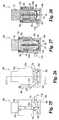
- FIG. 1is a cross-sectional view of a bodily fluid sampling device according to one embodiment of the present invention.
- FIG. 2is a cross-sectional view of the FIG. 1 device during lancing at an alternate site.
- FIG. 3is a cross-sectional view of the FIG. 1 device expressing fluid from the alternate site.
- FIG. 4is a cross-sectional view of the FIG. 1 device configured to lance.
- FIG. 5is a cross-sectional view of the FIG. 1 device lancing a fingertip site.
- FIG. 6is a cross-sectional view of a bodily fluid sampling device according to according to another embodiment.
- FIG. 7is a cross-sectional view of the FIG. 6 device configured to express fluid from an alternate site.
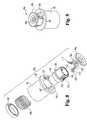
- FIG. 8is an exploded view of the FIG. 6 device.
- FIG. 9is a perspective view of the FIG. 6 device.
- FIG. 10is a perspective view of a lancing device according to a further embodiment of the present invention.
- FIG. 11is a cross-sectional view of the FIG. 10 device.
- FIG. 12is a perspective view of the FIG. 10 device configured for a deep penetration depth.
- FIG. 13is a perspective view of the FIG. 10 device configured for a shallow penetration depth.
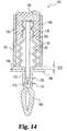
- FIG. 14is a cross-sectional view of a lancing device according to another embodiment.
- FIG. 15is an exploded view of a sampling device according to a further embodiment.
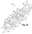
- FIG. 16is a perspective view of the FIG. 15 device.
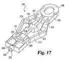
- FIG. 17is a perspective view of the FIG. 16 in an armed configuration.
- FIG. 18is a perspective view of a sampling device according to another embodiment.
- FIG. 19is a top perspective view of the FIG. 18 device in a lancing position.
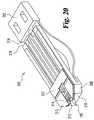
- FIG. 20is a bottom perspective view of the FIG. 18 device in a lancing position.
- FIG. 21Ais a top perspective view of a sampling device according to a further embodiment.
- FIG. 21Bis a bottom perspective view of the FIG. 21A device.
- FIG. 22is a perspective view of an adjustable holder according to another embodiment holding the FIG. 21A device.
- FIG. 23is an exploded view of a sampling device according to another embodiment.
- FIG. 24is a perspective view of the FIG. 23 device.
- FIG. 25is a front view of the FIG. 23 device.
- FIG. 26is a side view of the FIG. 23 device.
- FIG. 27is a cross-sectional view of the FIG. 23 device configured to express fluid from a fingertip.
- FIG. 28is a cross-sectional view of the FIG. 23 device configured to express fluid from an alternate site.
- FIG. 29a front view of a sampling device according to a further embodiment.
- FIG. 30is a cross-sectional view of the FIG. 29 device configured to express fluid from a fingertip.
- FIG. 31is a cross-sectional view of the FIG. 29 device configured to express fluid from an alternate site.
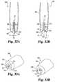
- FIGS. 32A and 32Bare cross sectional views of a sampling device according to another embodiment in lancing and expressing configurations, respectively.
- FIGS. 33A and 33Bare perspective views of the FIGS. 32A and 32B device in the lancing and expressing configurations, respectively.
- FIGS. 34A and 34Bare cross sectional views of a sampling device according to a further embodiment in extended and retracted configurations, respectively.
- FIGS. 35A and 35Bare perspective views of the FIGS. 34A and 34B device in the extended and retracted configurations, respectively.
- FIGS. 36A and 36Bare cross sectional views of a sampling device according to still yet another embodiment in lancing and expressing configurations, respectively.
- FIGS. 37A and 37Bare perspective views of the FIGS. 36A and 36B device in the lancing and expressing configurations, respectively.
- FIGS. 38A and 38Bare cross sectional views of a sampling device according to a further embodiment in lancing and expressing configurations, respectively.
- FIGS. 39A and 39Bare perspective views of the FIGS. 38A and 38B device in the lancing and expressing configurations, respectively.
- FIGS. 40A and 40Bare cross sectional views of a sampling device according to another embodiment in lancing and expressing configurations, respectively.
- FIGS. 41A and 41Bare perspective views of the FIGS. 40A and 40B device in the lancing and expressing configurations, respectively.
- FIGS. 42A and 42Bare cross sectional views of a sampling device according to still yet another embodiment in lancing and expressing configurations, respectively.
- FIG. 43is a perspective view of a sampling device according to a further embodiment.
- FIG. 44is a front view of the FIG. 43 device.
- FIGS. 45A and 45Bare cross sectional views of the FIG. 43 device in lancing and expressing configurations, respectively.
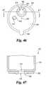
- FIG. 47is a cross sectional view of the FIG. 46 device as taken along line 47 - 47 in FIG. 46 .
- FIGS. 48A and 48Bare cross sectional views of a sampling device according to another embodiment in lancing and expressing configurations, respectively.
- FIGS. 49A and 49Bare top views of the FIGS. 48A and 48B device in the lancing and expressing configurations, respectively.
- FIGS. 50A and 50Bare perspective views of the FIGS. 48A and 48B device in the lancing and expressing configurations, respectively.
- FIG. 51is a top view of a sampling device according to another embodiment in a lancing configuration.
- FIG. 52is a cross sectional view of the FIG. 51 device in an expressing configuration.
- FIG. 53is a cross sectional view of the FIG. 51 device as taken along line 53 - 53 in FIG. 51 .
- FIGS. 54A and 54Bare perspective views of a sampling device according to a further embodiment in lancing and expressing configurations, respectively.
- FIGS. 55A and 55Bare cross sectional views of the FIGS. 54A and 54B device in the lancing and expressing configurations, respectively.
- FIG. 56is a top view of a sampling device according to another embodiment.
- FIGS. 57A and 57Bare cross sectional views of the FIG. 56 device in lancing and expressing configurations, respectively.
- FIG. 58is a perspective view of a sampling device according to still yet another embodiment.
- FIG. 59is an exploded view of the FIG. 58 device.
- FIG. 60is a perspective view of a cross section of a sampling device according to a further embodiment.
- FIG. 61is a perspective view of the FIG. 60 device in a lancing configuration.
- FIG. 62is a perspective view of the FIG. 60 device in an expression configuration.
- Bodily fluid sampling devicesare operable to form an incision with a precise depth and express fluid from both fingertip and alternate sites.
- the devicescan further be configured to allow for the adjustment of the penetration depth of the lancet.
- the deviceincludes a reference member that provides a reference surface for controlling the penetration depth of a lancet.
- the reference memberis received in a large expression opening of an expression member.
- the reference memberflattens the skin in the expression opening such that an incision with a precise depth can be formed.
- the reference membercan be retracted from the expression opening so that the larger expression opening can be used to express a sufficient amount of bodily fluid from the alternate site.
- a springautomatically retracts the reference member after lancing, and in other forms, cam mechanisms are used to retract the reference member during expression of the fluid.
- the reference memberis coupled to the lancet in order to control the penetration depth of the lancet. Further aspects of the present concern integrated sampling devices that allow test media to be attached to the lancet after sterilization so as to ensure that the test media remains properly calibrated.
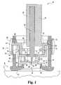
- FIGS. 1-5A bodily fluid sampling device 40 according to one embodiment of the present invention is illustrated in FIGS. 1-5 .
- the sampling device 40includes an incision forming member 42 , a penetration depth adjuster 44 , an expression member 46 , and a reference member 48 .
- other components of the sampling device 40that are well know in the art, such has hammers, cocking mechanisms and the like that are not important to appreciate the present invention, will not be discussed below.
- the device 40 illustrated in FIG. 1can be back loaded into a sampling device of the type described in U.S. Pat. No. 5,964,718.
- the incision forming member 42has a lancet 58 that is attached to a lancet body 50 .
- the lancet 50is in the form of a needle.
- the lancet 50can come in other forms, such as a blade.
- the incision forming member 42in other embodiments can include multiple lancets 50 .
- the lancet body 52has a depth stop surface 54 , which is used to control the penetration depth of the lancet 50 .
- the lancet 50further includes a flange 56 positioned proximal to tip 58 of the lancet 50 , which is configured to cut the skin S.
- the flange 56can be used as an auxiliary stop in order to prevent over penetration of the lancet 50 into the skin S.
- the sampling device 40has a depth control assembly 59 that is able to adjust the penetration depth of the lancet 50 .
- the depth control assembly 58includes adjuster 44 and reference member 48 .
- the adjuster 44has an outer adjustment member 60 attached to an inner adjustment member 62 that interfaces with the reference member 48 .
- the outer expression member 46defines a slot 64 through which arm 66 of the adjuster 44 connects the outer adjustment member 60 to the inner adjustment member 62 .
- the outer adjustment member 60 in the illustrated embodimentis in the form of a ring that encircles the outer expression member 46 .
- the userrotates the outer adjustment member 60 around the device 40 .
- the inner adjustment member 62further incorporates an outwardly extending flange 68 that engages an inwardly extending flange 70 in the outer expression member 46 . As shown in FIG. 1 , the inner adjustment member 62 defines an inner passageway 72 through which the lancet 50 extends. Inside passageway 72 , the inner adjustment member 62 has a stop flange 74 that is configured to engage the stop surface 54 on the incision forming member 42 .
- the inner adjustment member 62has at least one thread 76 that engages a corresponding groove 78 formed in the reference member 48 .
- the reference member 48can be threaded and the inner adjustment member 62 can have corresponding grooves.
- the reference member 48surrounds the inner adjustment member 62 in the illustrated embodiment, at least a portion of the reference member 48 in other embodiments can be received inside the inner adjustment member 62 .
- the outer expression member 46has a slot 80 that engages the reference member 48 .
- the reference member 48has a contact portion 82 that is adapted to extend through expression opening 84 that is defined in the expression member 46 .
- the contact portion 82has a skin contacting surface 86 that contacts the skin S when the incision is formed by the lancet 50 .
- Surface 86surrounds an aperture 88 through which tip 58 of the lancet 50 extends.
- Distance D 1 between the skin contacting surface 86 and stop surface 89 on the stop flange 74 of the adjuster 44controls the penetration depth of the lancet 50 .
- Rotating the outer adjustment member 60changes distance D 1 , thereby changing the penetration depth of the lancet 50 .
- Extending around opening 84 in the outer expression member 46is a ridge 90 that is adapted to engage the reference member 48 so as to control how far the contact portion 82 extends from the expression member 46 .
- the outer expression member 46further has an expression surface 92 that is angled or inclined towards opening 84 in order to promote expression of bodily fluid.
- the expression surface 92has a generally frusto-conical shape.
- An opening size adjustment or retraction mechanism 93is used to retract reference member 48 from the expression opening 84 so as to change the opening size for expressing fluid.
- mechanism 93includes a spring 94 .
- spring 94which is positioned between the outer expression member 46 and the reference member 48 , biases the reference member 48 along with the adjuster 44 against flange 70 so that the contact portion 82 is positioned out of the expression opening 84 .
- alternate sampling sites Asuch as the palm of the hand, forearm, earlobe and the like, may be useful for sampling because lancing these sites tends to be less painful.
- one drawback with the alternate site Ais that the amount of fluid that can be expressed from an incision formed in that area is relatively small when compared to fingertip sites.
- One solutionhas been to increase the opening size in an expression ring so as to increase the area in which fluid is expressed from the skin.
- the skintends to bulge to a greater degree, thereby increasing the penetration depth of the lancet by a variable amount when the incision is formed at the alternate site A.
- the expression opening 84is sized to express a sufficient amount of fluid for testing from the alternate site A.
- the aperture 88 in the reference member 48is relatively small.
- the aperture 88is sized to be slightly larger than the lancet tip 58 such that the lancet 50 is able to slide through the aperture 88 .
- the size of the reference member 48minimizes skin deformation around the lancet 50 when piercing the skin S, thereby ensuring the device 40 forms incisions with substantially consistent depths.
- the incision forming member 42is actuated to move towards the skin S.
- the incision forming member 42can be driven towards the skin S through a number of mechanisms, such as for example by a hammer striking the incision forming member 42 .
- the stop surface 54 of the incision forming member 42contacts the inner flange 74 of the adjuster 44 such that the reference member 48 is driven toward the skin S.
- the arm 66 of the adjuster 44slides within the slot 64 of the outer expression member 46 .
- the contact portion 84 of the reference member 82extends through the expression opening 84 such that the skin contacting surface 86 of the reference member 48 contacts and flattens the skin S surrounding the lancet 50 as incision I is formed.
- the distance D 1 between the skin contacting surface 86 and the stop surface 89 of the stop flange 74controls the penetration depth P 1 of the lancet 50 in to the skin S.
- the spring 94retracts the reference member 48 from the expression opening 84 .
- the useris able to express bodily fluid B from the incision I using the larger expression opening 84 .
- this designallows a greater amount of fluid to be expressed from an alternate site A, while at the same time forms an incision having precise depth.
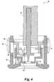
- the penetration depth of the lancet 50can be adjusted by rotating the outer adjustment member 60 of the adjuster 44 .
- rotating the outer adjustment member 60 of the adjuster 44extends the reference member 48 from the adjuster 44 , thereby increasing distance D 2 between the skin contacting surface 86 of the reference member 48 and the flange 74 of the adjuster 44 .
- Increasing distance D 2in turn reduces the penetration depth P 2 of the lancet 50 , as is illustrated in FIG. 5 . Reducing the penetration depth P 2 can help reduce the pain associated with lancing at especially sensitive sites, such as fingertip site F.
- a bodily fluid sampling device 40 aaccording to another embodiment of the present invention will now be described with reference to FIGS. 6-9 .
- the sampling device 40 a of the illustrated embodimentis configured to automatically increase the size of the expression opening when fluid is expressed from an alternate site.
- the sampling device 40 aincludes a sleeve 96 that encloses incision forming member 42 , which has lancet 50 and lancet body 52 , of the type described above.
- surface 54 of the lancet body 52does not act as an end stop for controlling the penetration depth of the lancet 50 . Rather, a fixed stop inside the mechanism that is used to actuate the lancet 50 controls the penetration depth.
- device 40 acan be incorporated into a SOFTCLIX brand lancing device (Boehringer Mannheim GmbH Corporation, Germany) in order to actuate and control the penetration depth of the lancet 50 . It is contemplated, however, that device 40 a can be modified such that surface 54 of the lancet body 52 can act as a stop surface for controlling the penetration depth of the lancet 50 .
- the sleeve 96is slidable over a lancet housing 98 . As shown, the lancet housing 98 encloses the incision forming member 42 .
- a spring 100is operatively positioned between the sleeve 96 and the housing 98 for biasing the sleeve 96 .
- the sleeve 96is attached to a nut or inner flange 102 against which the spring 100 engages, and in a similar fashion, the housing 98 has an outwardly extending flange 104 that engages the spring 100 .
- the nut 102threadedly engages the sleeve 96
- the nut 102is integrally formed with the sleeve 96 .
- nut 102 and flange 104can be attached in other manners.
- the sleeve 96further includes one or more guide arms 106 that longitudinally extend from the sleeve 96 .
- the sleeve 96has a pair of guide arms 106 .
- Each guide arm 106has an end stop member 107 that extends in an inward radial direction so as to engage flange 104 of the housing 98 .
- the sleeve 96further has an outer collar 108 that assists the user in gripping the sleeve 96 .
- the housing 98has guide ridges 109 that longitudinally extend on opposite sides of the guide arms 106 , as shown in FIG. 8 .
- the sampling device 40 a illustrated in FIGS. 6-9includes an outer expression member or tip 46 a as well as a reference member 48 a .
- the reference member 48 ahas aperture 88 and skin contacting portion 82 with skin contacting surface 86 .
- the expression tip 46 ahas angled expression surface 92 that surrounds expression opening 84 .
- the expression tip 46 ais glued to the housing 98 , and in the another embodiment, the expression tip 46 a is integrally formed with the housing 98 . It should be understood that the expression tip 46 a can be attached to the housing 98 in other manners as generally know by those skilled in the art.
- the penetration depth of the lancet 50is control by a fixed stop in the actuation mechanism, such as with a SOFTCLIX brand lancing device. It contemplated that the lancet 50 in the sampling device 40 a can be constructed to have a fixed penetration depth or an adjustable penetration depth, as in the manner described above for the previous embodiment by adjusting registration between the reference member 48 a and the lancet body 52 .
- the sampling device 40 a of the embodiment illustrated in FIGS. 6-9is designed to automatically retract the skin contacting portion 82 of the reference member 48 a from the expression opening 84 when expressing fluid from an alternate site A.
- the skin contacting portion 82 of the reference member 48 ais positioned within the expression opening 84 .
- the sampling device 40 aincorporates a retraction mechanism 110 that includes one or more cam arms 112 pivotally mounted to the housing 98 .
- the retraction mechanism 110incorporates a pair of cam arms 112 , but it should be appreciated that the retraction mechanism 110 can have more or less cam arms 112 than is shown.
- the cam arms 112pivot about housing pivot pins 114 , which are received in pivot slots 116 defined in the housing 98 .
- Each of the cam arms 112extend through cam arm openings 118 in the housing 98 and engage at one end a cam groove or surface 120 that is defined in the guide arms 106 .
- the other end of each of the cam arm 112is engage with the reference member 48 a through aperture pin 122 that is received in cam slot 124 defined in the reference member 48 a .
- pin 122extends within a cavity 123 ( FIG. 8 ) defined in each cam arm 122 .
- the skin contacting portion 82 of the reference member 48 ais positioned in the expression opening 84 in order to control the penetration depth of the lancet 50 .
- the spring 100biases the sleeve 96 away from the expression tip 46 a which in turn, through the guide arms 106 , orients the cam arms 112 so as to position the reference member 48 a in the expression opening 84 .
- the skin contacting portion 82 of the reference member 48 ais retracted from the expression opening 84 such that the bodily fluid can be expressed from the alternate site using the wider expression opening 84 .
- the usergrasps the device 40 a by sleeve 96 and presses the expression tip 46 a against the skin S.
- the sleeve 96slides in direction E along the housing 98 , and the spring 100 becomes compressed.
- the stiffness of the spring 100is selected such that spring 100 will compress during expression, but will typically not compress during lancing.
- the guide arms 106pivot the cam arms 112 such that the reference member 48 a is retracted into the device 40 a .
- the spring 100returns the sleeve 96 to the original position shown in FIG. 6 , and the cam arms 112 return the reference member 48 a back into the expression opening 84 .
- the incision forming member 130includes a body portion 132 , a reference member 133 , a safety cover 134 and a lancet 136 .
- the body portion 132 , the reference member 133 and the safety cover 134are made of plastic; while lancet 136 is made of metal. As should be appreciated, these components can be made of other materials.
- the body portion 132has a pair of opposing notches 138 that are used secure the incision forming member 130 to the bodily fluid sampling device.
- the safety cover 134covers the lancet 136 before use.
- the safety cover 134can be used to ensure the sterility of the lancet 136 .
- the safety cover 134can then be removed from the lancet 136 , as illustrated in FIGS. 11-13 .
- the safety cover 134is integrally molded with the body portion 132 such that the safety cover 134 can be removed by twisting the cover 134 off the body portion 132 .
- the safety cover 134is separate from the body portion 132 .
- the lancet 136 in FIG. 11is configured to form an incision in the skin.
- the lancet 136can be a blade, a needle or the like.
- the reference member 133is attached to the body 132 of the incision forming member 130 in order to control the penetration depth of the lancet 136 .
- the incision forming member 130is received inside the expression member 46 .
- the retraction mechanism 93 used in the illustrated embodimentis spring 94 , which is engaged between the expression member 46 and the reference member 133 .
- the reference member 133has contact portion 82 with skin contacting surface 86 that controls the penetration depth of the lancet 136 . After the incision is formed, the incision forming member 130 along with the reference member 133 are retracted by spring 94 such that the contact portion 82 is removed from the expression opening 84 in the expression member 46 .
- the larger expression opening 84can be used to express bodily fluid. It is contemplated, however, that the reference member 133 can be retracted in other manners.
- incision forming member 130can be incorporated into a SOFTCLIX brand lancing device that can be used to actuate and retract the incision forming member 130 .
- the reference member 133 and the body portion 132are threadedly mated together.
- the reference member 133 and the body portion 132can be threadedly mated during the molding process for the parts. As shown in FIG.
- the reference member 140has an internally threaded portion 140 that engages an externally threaded portion 142 on the body portion 132 of the incision forming member 130 .
- the reference member 133has one or more wing members 144 extending therefrom that engage spring 94 and are used to help turn the reference member 133 relative to the body portion 132 .
- the penetration depth of the lancet 136can be reduced by rotating the reference member 133 in a counterclockwise direction C.
- the incision forming member 130can be threaded differently such that the penetration depth is increased by rotating the reference member 133 in the counterclockwise direction C.
- FIG. 14An incision forming member assembly 150 according to another embodiment of the present invention is illustrated in FIG. 14 .
- the assembly 150includes a body 152 and lancet 136 attached to the body 152 .
- living hinges 154or other spring means resiliently attach a reference member portion 155 to the remainder of the body 152 .
- Notches 138are defined in the body 152 to secure the body to a holder 156 .
- the holderhas external threads 158 that mate with internal threads 160 on depth control member 162 .
- the depth control member 162has a contact edge 164 configured to contact a stop flange 166 on the reference member portion 155 .
- Assembly 150further includes a safety cover 168 that covers the lancet 136 in order to protect the user and provide a sterile environment for the lancet 136 .
- a skin contact portion 170extends from the stop flange 166 along the lancet 136 .
- a groove or an area of weakness 172is formed so that the cover 168 can be detached from the skin contact portion 170 to expose the lancet 136 .
- a skin contacting surface 174is formed at groove 172 .
- Assembly 150is used in conjunction with an expression member 46 of the type described above. As previously mentioned, variations in skin height due to factors, such as the pressure applied to the skin, the type of skin and the skin location, can significantly alter the penetration depth of traditional lancing devices. Assembly 150 is constructed to contact the skin before lancing will occur, which in turn provides a reference surface for controlling the penetration depth into the skin. During lancing, the skin contact portion 155 extends through the expression opening 84 in the expression member 46 , and the skin contacting surface 174 of assembly 150 contacts the skin. As the skin contacting surface 174 is pressed against the skin by the actuation of the lancet assembly 150 , the living hinges 154 are compressed until the stop edge 164 contacts flange 166 .
- the distance D 3 between edge 164 and flange 166controls the penetration depth of the lancet 136 .
- Increasing distance D 3 by rotating the depth control member 162 relative to holder 156deepens the penetration depth of the lancet 136 .
- reducing the distance D 3 between edge 164 and flange 166decreases the penetration depth of the lancet 136 .
- the living hinges 154aid in retracting the lancet 136 from the incision.
- Lancing assembly 180integrates a number of features into a single device; while at the same time allows for sterilization of the lancet without affecting the test strip.
- Assembly 180includes an incision forming member 182 , test media 184 , and a carrier 186 .
- the incision forming member 182which is used to form an incision in the skin, has a head 188 , a lancet 190 , a pry member 192 , and a safety cover 194 .
- the head 188 and the cover 194are positioned at opposite ends of the lancet 190 , and the pry member 192 is positioned along the lancet 190 , between the head 188 and the cover 194 .
- the head 188has a pair of lock notches 196 for locking the incision forming member 182 in an armed position.
- the lancet 190 in the illustrated embodimentis a needle.
- lancet 190can include other types of instruments that are used to from incision, such as blades for example.
- the pry member 192has a pair of pry surfaces 198 that are angled towards the lancet 190 . To make insertion of the incision forming member 182 into the carrier easier, surfaces 198 are rounded.
- the safety cover 194includes covering tip 200 of the lancet 190 (see FIG. 17 ) in order to maintain the sterility of the lancet 190 . Moreover, the cover 194 protects users from accidentally cutting themselves. As illustrated, the cover 194 in the illustrated embodiment has a general cylindrical shape with an alignment flange 202 extending therefrom at one end. The cover 194 further has an opening 204 that is normally sealed so as to maintain the sterility of the lancet tip 200 .
- the head 188 and the pry member 192are made from a hard plastic; the cover 194 is made of a soft plastic; and the lancet 190 is metallic. As should be appreciated, these components can be made from other types of materials.
- the test media 184is used for determining analyte levels in the bodily fluid sample.
- analyte levelscan be determined through the chemical, electrical, electrochemical and/or optical properties of the bodily fluid sample collected on the test media, to name a few.
- the test media 184 in the illustrated embodimentis a chemically reactive reagent test strip.
- reagent test stripsare sensitive to thermal and/or chemical processes required for sterilization. The sterilization process can affect the results generated by the test media 184 , and therefore, recalibration of the test media 184 is required after sterilization.
- the incision forming member 182can be separately sterilized such that the test media 184 does not have to go through the same sterilization process as the incision forming member 182 . After sterilization, the incision forming member 182 can be installed in the carrier 186 , thereby eliminating the need to recalibrate the test media 184 .
- the carrier 186has a pair of lock arms 206 that define a receptacle 208 in which the head 188 is locked when the lancet 182 is in the armed position, as is shown in FIG. 17 .
- Each lock arm 206has a lock tab 210 that is constructed to engage a corresponding notch 196 in the head 188 .
- the carrierhas a connector 211 with a slot 212 in which the lancet 190 is slidably received.
- the carrier 186further includes a pair of living hinges 214 that connect the lock arms 206 to sampling portion 216 of the lancing assembly 180 .
- the living hinges 214have notches 218 that allow the living hinges 214 to bend.
- Each of the living hingeshas two outwardly opening notches 220 that are located proximal the connector 211 and the sampling portion 216 . Between the outwardly opening notches 220 , each living hinge 214 has an inwardly opening notch 222 .
- the living hinges 214have expansion members 224 that are connected together by a tamper evidence link 226 .
- Each expansion memberhas a pry surface 228 , and the pry surfaces 228 are constructed to define a pry member cavity 230 that receives the pry member 192 of the incision forming member 182 .
- the pry surfaces 228are angled and are concavely shaped to coincide with the shape of the surfaces 198 on the pry member 192 .
- the carrier 186further includes a cover receptacle 280 that defines a safety cover cavity 282 in which the safety cover 194 of the incision forming member 182 is received.
- cavity 282includes an alignment slot 284 that is configured to receive the alignment flange 202 of the safety cover 194 .
- the sampling portion 216 of the carrier 186defines a test media cavity 286 in which the test media 184 is housed during use. Inside the test media cavity 286 , the sampling portion 216 further has a capillary channel 288 .
- the capillary channel 288is configured to allow the lancet 182 to extend therethrough during lancing and is configured to draw fluid onto the test media 184 during sampling.
- the test media 184is slightly spaced away from the sampling portion 216 in order to define a flat capillary space for spreading the fluid sample across the test media 184 .
- a cross member 289extends across a portion of the channel 288 proximal the cover 194 so as to prevent removal of the incision forming member 182 when the assembly 180 is armed.
- the channel 288fluidly communicates with an aperture 290 defined in skin contacting portion 292 .
- the skin contacting portion 292has a skin contacting surface 294 that contacts and flattens the skin around the aperture 290 so that the lancet 182 can cut an incision with a precise depth.
- the head 188is pushed into the receptacle 208 such that the lock arms 206 engage and lock with the notches 196 in the head 188 , as is illustrated in FIG. 17 .
- the pry member 192breaks the tamper evidence link 226 by prying the expansion members 224 apart, which in turn bends the living hinges 214 .
- the tamper evidence link 226provides a visual indicator of prior arming or use of the device 180 .
- the tip 200 of the lancet 182pierces through the sealed opening 204 in the cover 194 and extends into the capillary channel 288 .
- the cross member 289helps to prevent accidental removal of the incision forming member 182 after arming.
- the test media 184is not shown in FIG. 17 so that the tip 200 of the lancet 182 can be viewed when in the armed position and that the test media 184 is typically attached before arming in the illustrated embodiment.
- the tip 200 of the lancet 182 in one formis typically positioned within aperture 290 proximal the skin contacting surface 294 .
- assembly 180can be used to form an incision in the skin.
- the assembly 180is installed in a sampling device in one embodiment of the present invention.
- the assembly 180is armed by the sampling device, and in another form, the assembly is armed before installation in the sampling device.
- the skin contacting surface 292contacts the skin, and the tip 200 of the lancet 190 is driven through opening 290 .
- the incision forming member 182is actuated by a hammer, or a similar device, in order to strike the head 188 of the incision forming member 182 .
- the penetration depth of the lancet 190is controlled by an adjustable holder for assembly 180 of the type similar to the one described below with reference to FIG. 22 .
- distance D 4 between the pry member 192 and the cover 194controls the penetration depth of the lancet 190 .
- the living hinges 214are compressed. After the tip 200 of the lancet 190 is fully extended, the compressed living hinges 214 recoil, thereby retracting the lancet 190 .
- the bodily fluid from the incision formed by the lancet 190is collected through aperture 290 and is distributed across the test media 184 via capillary channel 184 .
- the annular space defined in aperture 290 between the lancet 190 and the skin contacting portion 292forms a low volume capillary for transporting the fluid.
- the fluidis then transferred to the flat capillary defined between the test media 184 and the sampling portion 216 in cavity 286 .
- the gapsare small (0.1 mm or less) to promote transfer of the fluid between the annular and flat capillaries.
- venting of the capillariesis accomplished via slots or channels 295 formed around cavity 286 .
- FIGS. 18-20A sampling device 300 according to another embodiment of the present invention is illustrated in FIGS. 18-20 .
- FIG. 18depicts the device 300 prior to lancing; while FIGS. 19 and 20 show the device 300 during lancing.
- Sampling device 300includes a head member 302 that has a pair of living hinges or leaf springs 304 .
- the head 302defines a pair of openings 306 that are used to secure the device 300 .
- the ends of the leaf springs 306 that are opposite the head 302are received in slots 306 defined in safety cover 308 .
- the safety cover 308encapsulates lancet 190 to protect the lancet 190 from outside contamination.
- the lancet 190is attached to the head 302 , and in another embodiment, the lancet 190 abuts the head 302 .
- the cover 308has an encapsulating surface 310 that covers the lancet 190 .
- the encapsulating surface 310 of the safety cover 308covers the lancet 190 .
- the tip 200 of the lancet 190pierces the encapsulating surface 310 of the cover 308 .
- the encapsulating surface 310includes soft foam and/or rubber that surround the tip 200 of the lancet 190 inside the cover 308 .
- the sampling device 300 illustrated in FIGS. 18-20allows test media 312 to be assembled to the remainder of the device after the lancet 190 has been sterilized.
- the test media 312is attached to the safety cover 308 , and the test media 312 has an overhang portion 313 that extends past surface 310 on the cover 308 .
- the test media 312is glued to the covers.
- the test media 312can be attached in other manners.
- the test media 312is operable to test analyte levels electrochemically.
- the test media 312is operable to test analyte levels optically.
- test media 312can test analyte levels using other techniques.
- the test media 312incorporates a capillary portion 314 for drawing bodily fluid into the test media 312 for testing.
- the overhang portion 313 of the test media 312ensures that capillary 314 is in close proximity to the skin.
- the capillary portion 314is surrounded by a skin contacting surface 315 that acts as the reference surface for controlling the penetration depth of the lancet 190 .
- the head 302 and the safety cover 308have opposing stop surfaces 316 and 318 that control the penetration depth of the lancet 190 .
- the distance between stop surfaces 316 and 318determines the penetration depth of the lancet 190 .
- spacers with varying thicknessesare placed between the stop surfaces 316 and 318 to adjust the penetration depth of the lancet 190 .
- FIGS. 21-22illustrate a sampling device 330 according to another embodiment of the present invention.
- device 330includes a housing 332 , a lancet or blade 334 slidably received in the housing 332 , and test media 336 .
- Housing 332has first 338 and second 340 sides that are attached together through a bead 342 to form a blade cavity 344 in which blade 334 is received.
- both the first 338 and second 340 sidesare generally flat to give the sampling device an overall flat appearance.
- bead 342is an adhesive bead that adheres the first 338 and second 340 sides together.
- the housing 332can be further subdivided into separate head 346 and skin contacting 348 portions.
- Blade 334is attached to the head 346 and is slidable within blade cavity 344 in the skin contacting portion 348 of the housing 332 .
- the first side 338 of the housing 332defines a living hinge or leaf spring 350 that connects the head 346 to the skin contacting portion 348 of the housing 332 .
- the head 346can further have notches 352 for securing device 330 to a holder.
- FIGS. 21 and 22illustrate the leaf spring 350 in a flexed state when blade 334 is extended from the housing 332 through opening 353 .
- the first side 338 of the housing 332has a skin contacting edge 354 that acts as a reference surface for controlling the penetration depth of the blade 334 .
- the second side 340 of the housing 332has a capillary slot 356 for drawing fluid via capillary action into the blade cavity 344 .
- the capillary slot 356 in the illustrated embodimenthas a gradual tapered shaped from opening 353 to improve fluid flow from the incision into the blade cavity 344 .
- capillary slot 356 as well as opening 353can be covered with a safety cover 358 that can be used to maintain the sterility of blade 334 and to protect the user from injury.
- a gapis formed around the blade 334 for drawing bodily fluid from the incision to the test media 336 via capillary action.
- the side of the blade 334 that faces the test media 336is coated and/or incorporates hydrophilic material, and the opposite side is coated and/or incorporates hydrophobic material.
- this constructionimproves the transfer of the fluid onto the test media 336 .
- the test media 336can be of the type described above and can be attached to the housing 332 in a number of manners.
- the test media 336can be a chemically reactive reagent strip that is glued to the housing.
- test media 336can be attached to the housing 332 after the blade 334 has been sterilized. Once attached, the test media 334 defines portion of the blade cavity 344 and fluid from slot 356 can be drawn to the test media 332 through the blade cavity 334 .
- a holder 360 for device 330 that is operable to adjust the penetration depth of the blade 334is illustrated in FIG. 22 .
- Holder 360has a cover 362 with a receptacle 364 in which device 330 is received and a depth control mechanism 366 that is coupled to the cover 362 .
- a test media view window 368is defined in the cover 362 so that the test media 336 can be viewed. Window 368 can allow the test media 336 to be analyzed optically.
- the depth control mechanism 366has a depth adjustment wheel 370 that is rotatably coupled to a bearing member 372 through rod 374 , and the bearing member 372 is attached to the cover 362 .
- the rod 374has a gear 376 that is engageable with an actuation gear 378 .
- Wheel 380only partially extends around rod 374 , thereby defining a gap 380 that allows device 330 to be mounted in holder 360 .
- the wheel 380has a series of steps 382 of graduated thickness, and the steps 382 of wheel 380 can be rotated through a slot 384 in the cover 362 .
- the actuation gear 378rotates the wheel 380 such that gap 380 is positioned in the slot 384 .
- Device 330is then slid into the receptacle 364 so that the head 346 of the device 330 is slid past slot 384 .
- the actuation gear 378rotates the wheel 380 such that at least one of the steps 382 is positioned in the slot 384 between the head 346 and the skin contacting portion 348 , thereby securing the device 330 to the holder 360 .
- the step 382 with the appropriate thicknesscan be positioned in the slot 384 between the head 346 and the skin contacting portion 348 so as to control the penetration depth of the blade 334 .
- the skin contacting edge 354contacts the surface of the skin.
- the skin contacting portion 348 of the housing 332slides within the receptacle 364 towards the head 346 of the device 330 such that the blade 334 is uncovered to lance the skin.
- the skin contacting portion 348 of the housing 332continues to retract until it engages the selected step 382 on the wheel 380 .
- the thickness of the step 382controls the penetration depth of the blade 334 .
- the leaf spring 350which became flexed during lancing, extends portion 348 of the housing 332 so as to recover the blade 334 .
- the skin contacting edge 354can remain positioned against the skin (or positioned proximal to the skin) such that the fluid from the incision is drawn via capillary action into the blade cavity 344 .
- the fluidis drawn onto the side of the blade that faces the test strip 336 , which is coated with hydrophilic material. From the blade cavity 344 , the fluid is then deposited onto the test strip 336 for testing.
- Lancing device 400is configured to automatically increase the size of the expression opening and maintain the larger sized expression opening when fluid is expressed from an alternate site.
- the lancing device 400includes an outer expression member or tip 46 b , a reference member 48 b , a cam arm 112 a , a sleeve 96 a , a latch mechanism 402 , a housing 98 a , spring 100 and nut 102 . Similar to the embodiments illustrated in FIGS.
- the reference member 48 bhas skin contacting portion 82 with skin contacting surface 86 that surrounds aperture 88 (see FIG. 27 ).
- the expression tip 46 b in FIG. 28has an expression surface 92 , which has a conical form, and the expression surface 92 surrounds expression opening 84 .
- the expression tip 46 bis attached to the sleeve 98 a , which is slidably received in the housing 98 a . In one form of this embodiment, the expression tip 46 b is glued to the sleeve 98 a . However, it is contemplated that the expression tip 46 b can be secured in other manners.
- the sleeve 98 adefines a pair guide slots 404 that are configured to receive a pair of guide bosses 406 on the reference member 48 b .
- the reference member 48 bcan have more or less guide bosses 406 than is shown.
- the guide bosses 406have a generally rectangular shape so as to align the reference member 48 b in the guide slots 404 .
- the housing 96 aAround the sleeve 98 a , the housing 96 a has stop arms 408 with stop members 410 that are adapted to engage a stop flange 104 a on the sleeve 98 a .
- the penetration depth of the lancet 50is controlled by the mechanism that is used actuate the lancet 50 , such as in a SOFTCLIX brand lancing device. It is contemplated, however, that the penetration depth of the lancet 50 can be controlled in other manners. For instance, the distance between the stop flange 104 a and the stop members 410 can be used to control the penetration depth of the lancet 50 .
- the cam arm 112 ais pivotally mounted. Both arm 412 and cam arm 112 a have pivot pin openings 414 and 416 in which a pivot pin 418 is received, as is shown in FIGS. 23-24 .
- the cam arm 112 ahas a link portion 420 that join two actuation members 422 that give the cam arm 112 a a general u-shape.
- the end of each actuation member 422 , opposite link 420has a reference member engaging slot 424 that are configured to engage cam arm pins 426 that extend from the guide bosses 406 on the reference member 48 b .
- the actuation members 422have a generally bowed shape so as to fit around the sleeve 98 a .
- each actuation member 422has a sleeve engaging pin 428 that are received in a corresponding pivot pin opening 430 in the sleeve 98 a .
- a lock arm portion 430 with a lock tab 432extends from one of the actuation members 422 .
- one end of the latch arm 402is pivotally mounted to the housing 96 a , and the other end of the latch arm 402 has a latch notch 434 configured to engage the lock tab 432 .
- gravityis used to position the latch arm 402 such that the latch arm is able to engage the lock tab 432 .
- the latch arm 402incorporates a spring for biasing the latch arm 402 toward the housing 96 a such that the latch arm 402 is able to engage the lock tab 432 on the cam arm 112 a . It should be appreciated that latch arm 402 can be biased in other manners.
- the device 400By being able to accurately control the penetration depth of the lancet 50 , the device 400 is able to safely lance and express fluid from both fingertips and alternate sites. As previously discussed, the actuation mechanism for the lancet 50 controls the penetration depth of the lancet 50 .
- spring 100is secured between the stop flange 104 a of the sleeve 98 a and the nut 102 , which is secured to the housing 96 a . Normally, as shown in FIG.
- the spring 100biases the sleeve 98 a with respect to the housing 96 a such that the cam arm 112 a positions the reference member 48 b in expression opening 84 of the expression tip 46 b so that the penetration depth can be precisely controlled during lancing.
- device 400is only used to lance the fingertip and is not used to express fluid from the fingertip because fingertips tend to provide an adequate fluid supply without the need to express the fluid.
- the usergrips and presses the housing 96 a towards the skin.
- the cam arm 112 apivots such that the reference member 48 b is retracted from the expression opening 84 .
- the retraction of the reference member 48 bcreates a large opening in which bodily fluid from an alternate site can be expressed.
- the lock tab 432 on the cam arm 112 alocks with the latch arm 402 .
- the latch arm 402can be disengaged from the lock tab 432 to return the device 400 to its original configuration, as illustrated in FIG. 27 .
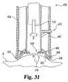
- FIGS. 29-31A fluid sampling device 450 according to a further embodiment of the present invention is illustrated in FIGS. 29-31 .
- the device 450has an actuation knob 452 at one end and a skin contacting or expression member 454 at the other end.
- the actuation knob 452is rotatably mounted on housing 456 , and the knob 452 can be rotated in order to change the shape and size of the expression member 454 .
- device 450is configured to precisely control the penetration depth of a lancet for safety purposes and is configurable to express fluid from finger as well as from alternate sites.
- device 450includes lancet 130 that is able to control and adjust its penetration depth, as was described above with reference to FIGS.
- device 450can use other types of lancing devices that can control penetration depth of the lancet, such as the embodiments illustrated in FIGS. 14-23 .
- the expression member 454has a lancet opening 458 through which lancet 130 is able to extend during lancing.
- the expression member 454is reconfigurable to change shapes depending on the expression site.
- the sampling device 450 in FIG. 30is configured to express fluid from a fingertip or similar site, and in FIG. 31 , device 450 is in a configuration to create a larger expression opening in order to express fluid from an alternate site.
- the sampling device 450has an inner tube 460 slidably mounted inside an outer tube 462 .
- the inner tube 460has a proximal end that is attached to the knob 452 .
- the distal end of the inner tube 460has a flange 464 that is rotatably coupled to a collar 464 such that the flange 464 is able to rotate relative to the collar 464 .
- living hinges 466connect the collar 464 to the outer tube 462 , and each living hinge 466 has a relief notch or portion 468 that allows the living hinge to bend. As shown, the living hinges 466 are covered by a covering 470 that defines opening 458 .
- the covering 470is made of a flexible material that is attached to the living hinges 466 .
- the covering 470can be made of flexible plastic, rubber or the like.
- the collar 466provides structural support around opening 458 so that the device 450 is able to express fluid from incision I in fingertip F. However, usually expressing the fingertip F is not required in order to obtain an adequate fluid sample.
- the sampling device 450further incorporates an actuation mechanism 472 that, in conjunction with knob 452 , retracts the inner tube 460 inside the outer tube 462 , thereby expanding the expression member 454 to the configuration illustrated in FIG. 31 .
- the actuation mechanism 472 in the illustrated embodimentincludes a guide pin 474 that extends from the inner tube 460 into a guide channel 476 in the outer tube 462 .
- the guide channel 476extends along a generally spiral shaped path on housing 456 .
- the guide channel 476is visible on the outside of the device in FIG. 29 , it is contemplated that the guide channel 476 can be enclosed so as to be invisible from the outside.
- the actuation mechanism 472operates in a fashion similar to that of a lipstick dispenser.
- the guide pin 474slides within channel 474 such that the distal end of the inner tube 460 is drawn inside of the outer tube 462 .
- the living hinges 468bend to create an expression opening 476 that is larger than opening 458 such that the device 450 is able to express fluid from alternate site A. As illustrated in FIG.
- the living hinges 466bend at middle notch 478 to form an outer expression edge 480 that defines expression opening 476 with an expression surface 482 .
- the expression surface 482has a conical shape. It is contemplated that the shape of the expression member 454 can be changed in other manners.
- the actuation mechanism 472 and inner tube 460are eliminated such that the user manually pushes in the expression member 454 to create a dented portion on the expression member 454 so that fluid can be expressed from an alternate site.
- FIGS. 32A-32B and 33 A- 33 BA body fluid sampling device 500 according to a further embodiment of the present invention is illustrated in FIGS. 32A-32B and 33 A- 33 B.
- the sampling device 500operates in a fashion similar to the one described above in FIGS. 29-31 .
- the sampling device 500is configured to be able to change its opening size for lancing and expressing fluid from both fingertips and alternate sites.
- the sampling device 500includes a housing 502 , a deformable cover or membrane 504 , a reference tube 506 and a lancet 50 .
- Reference tube 506is located inside the housing 502 , and the membrane 504 stretches between the ends of housing 502 and the reference tube 506 .
- the housing 502has an expression flange 508 that is rigid and defines an expression opening 510 for expressing fluid from alternate sites.
- the reference tube 506defines a lancet cavity 512 with an aperture or opening 514 through which the lancet 50 extends so as to lance the skin.
- the reference tube 506has a reference edge 516 with a reference surface 518 that flattens the skin during lancing.
- the membrane 504is attached around the reference edge 516 of the reference tube 506 , and in another embodiment, the membrane 504 is attached to and covers the reference surface 518 .
- the illustrated sampling device 500is operable to create two differently sized openings, one size for lancing and another size for expressing fluids from alternate sites. Similar to some of the previous embodiments, the penetration depth of the lancet 50 is controlled by a fixed stop in the actuation mechanism, such as with a SOFTCLIX brand lancing device.
- Sampling device 500 in FIG. 32Ais illustrated in its lancing configuration such that the sampling device 500 has a first opening size S 1 that is sized to flatten the skin around the lancet 50 during lancing.
- the first opening size S 1is based on the diameter of opening 514 , and in one particular form, the first opening size S 1 is at most 2.5 mm so as to flatten the skin during lancing.
- the first opening size S 1 in other formscan be sized differently.
- the lancing and expressing openings in a number of embodiments throughout the present descriptionhave a circular shape, it should be appreciated that these openings can be shaped differently.
- the reference tube 506can be retracted further inside the housing 502 to form a second opening size S 2 ( FIG. 32B ) for expressing fluid from alternate sites.
- the second opening size S 2is based on the diameter of the expression opening 510 , and in one particular form, the first opening size S 1 is at least 7.0 mm so as to provide an adequate opening size for expressing fluids from alternate sites. In other forms, the second opening size S 2 can be sized differently.
- the expression flange 508 around the expression opening 510provides a rigid member for expressing fluid.
- the sampling device 520includes a housing 522 and a cap 524 mounted to the housing in an extendable manner. Inside the housing 522 , lancet 50 with a lancet cartridge housing 526 is mounted. In the illustrated embodiment, the penetration depth of the lancet 50 is controlled by a fixed stop in the actuation mechanism, such as with a SOFTCLIX brand lancing device.
- the cap 524is adjustable relative to the housing 522 so as to be able to extend ( FIGS. 34A and 35A ) and retract ( FIGS.
- the cap 524defines a lancet opening 528 through which the lancet 50 is able to extend.
- the cap 524has a finger receiving cavity 530 that is sized and shaped to coincide with the contour of a fingertip.
- the finger receiving cavity 530has a semispherical shape.
- An expression ridge 532 that is configured to express fluid from alternate skin sitessurrounds the finger receiving cavity 530 .
- ridge 532is continuous, but it is contemplated that in other embodiments, the expression ridge 532 can be discontinuous.
- the expression ridge 532 in other formscan include notches to permit blood flow.
- the actuation mechanism for the lancet 50extends the lancet 50 at a predetermined stroke length.
- the cap 524is extended, as is depicted in FIGS. 34A and 35A , to decrease the penetration depth of the lancet 50 , and the cap 524 is retracted, as is shown in FIGS. 34B and 35B , to increase the penetration depth of the lancet 50 .
- the sampling device 520includes an adjustment mechanism 534 that adjusts the relative positions of the cap 524 and the housing 522 .
- the adjustment mechanism 534includes a ridge 536 in the housing 522 that engages a series of grooves 538 formed in the cap 524 .
- the grooves 538 in the illustrated embodimentare formed at predefined extended and retracted positions. For instance, when lancing a fingertip, the fingertip is received inside the finger receiving cavity 530 , and since the fingertip in cavity 530 is closer to the lancet 50 , the cap 524 is extended so as to reduce the penetration depth of the lancet 50 . The cap 524 is extended such that the ridge 536 in the housing 524 engages the groove 538 in the cap 524 to secure the cap 524 at the extended position.
- the sampling device 520lances an alternate site, such as a forearm
- the skin at the alternate sitedoes not bulge to a great extent inside the fingertip receiving cavity 530 .
- the cap 524can be retracted, as shown in FIGS. 34B and 35B , and the cap 524 is secured in the retracted position through the engagement between the ridge 536 and the groove 538 at the retracted position.
- the adjustment mechanism 534can include other types of adjustment mechanisms.
- the cap 524can be threaded onto the housing 522 such that the cap 524 can be extended and retracted.
- the fluid from the incisionby pressing the expression ridge 532 around the incision.
- the size S 2 of the finger expression cavity 530is larger than the size S 1 of lancet opening 528 so that the cap 524 is able to better express fluid from the alternate site.
- the size S 1 of the lancet opening 528is at most 2.5 mm
- the size S 2 of the finger receiving cavity 530is at least 7.0 mm.
- the opening sizescan be sized differently.
- the sampling device 540includes an expression cap 542 for expressing fluids from alternate sites, a priming mechanism 544 for priming lancet 50 , a housing 546 , a firing button 548 to fire the lancet 50 , and a lancing cap 550 .
- the expression cap 542covers one end of the priming mechanism 544 , as is shown in FIG. 36A .
- the priming mechanism 544is constructed so that the expression cap 542 must cover he priming mechanism 544 before the sampling device 540 can be primed, and in another form, the expression cap 542 is not required to prime the sampling device 540 .
- the sampling device 540 in the illustrated embodimentoperates in a fashion similar to a SOFTCLIX brand lancing device. With the expression cap 542 covering the priming mechanism 544 , the priming mechanism 544 is pressed toward the housing 546 into a cocked or primed position, as is illustrated in FIG. 37A . The lancet 50 can be fired by pressing the firing button 548 so as to lance the skin.
- the lancing cap 550defines a lancet opening 552 through which the lancet 50 extends during lancing.
- the lancet opening 552is sized to flatten the skin around the lancet 50 so as to control the penetration depth of the lancet 50 .
- the lancet opening 552has size S 1 that is not greater than 2.5 mm, but in other forms, the lancet opening 552 can be sized differently.
- the sampling device 540can be configured to express fluids from alternate sites, such as the forearm.
- the expression cap 542is removed from the priming mechanism 544 and then fitted over the lancing cap 550 .
- the expression cap 542is sized so that the expression cap 542 is able to be frictionally secured to the lancing cap 550 .
- the expression cap 542defines an expression opening 554 in which fluid from an incision at an alternate site is expressed.
- the expression opening 554is sized so that an adequate amount of fluid can be expressed by pressing the expression cap 542 around the incision.
- the expression opening 554has size S 2 that is at least 7.0 mm, but in other forms, the expression opening 554 can be sized differently. After expressing fluid from the incision, the expression cap 542 can be cleaned for reuse, or discarded and replaced with a new one.
- FIGS. 38A-38B and 39 A- 39 Billustrate a body fluid sampling device 556 , according to another embodiment, that utilizes a flip cap 558 in order to change opening sizes.
- the flip cap 558is pivotally attached to housing 560 through a pivot pin 562 .
- the housing 560has a cap protrusion 564 around which the flip cap 558 is received when in a closed position, as is depicted in FIGS. 38A and 39A .
- the cap protrusion 564defines an expression opening 566 for expressing fluid
- the flip cap 558has a lancet opening 568 through which lancet 50 in cartridge 526 is able to extend and lance the skin.
- the lancet opening 568has is sized (S 1 ) so as to be able to flatten the skin around the lancet 50 during lancing, thereby minimizing variations in penetration depth.
- the size S 1 of the lancet opening 568is at most 2.5 mm, and in other embodiments, the size S 1 of the lancet opening 568 can be different.
- the flip cap 558covers the expression opening 566 during lancing such that lancet 50 passes through the lancet opening 568 . After lancing, the flip cap 558 can be flipped away from the housing 556 , as illustrated in FIGS. 38B and 39B , so that the sampling device 556 can express fluid from alternate sites.
- the expression opening 566is sized (S 2 ) so as to be able to expression an adequate sample size of fluid from the incision.
- the size of the expression opening 566is at least 7.5 mm, but in other forms, the expression opening 566 is sized differently.
- FIGS. 40A-40B and 41 A- 41 BA body fluid sampling device 570 according to a further embodiment of the present invention is illustrated in FIGS. 40A-40B and 41 A- 41 B. Similar to the previously described embodiments, the sampling device 570 is able to change opening sizes for lancing and expressing fluid.
- the sampling device 570includes a lancet 50 with a cartridge 526 and a ball member 572 , which can be rotated in order to change the opening sizes.
- the ball member 572is rotatably mounted at one end of housing 574 in the sampling device 570 .
- the ball member 572 in the embodiment illustrated in FIGS. 40A-40Bis pivotally mounted onto one or more pivot pins 576 in the housing 574 .
- the ball member 572 in other embodimentscan be rotatably coupled to the housing 574 in other manners.
- the ball member 572 in another embodimentcan be mounted in a fashion similar to that of a ball point pen such that the ball member 572 is able to rotate about multiple axes.
- the ball member 572has a lancet bore 578 through which the lancet 50 extends during lancing and an expression bore 580 in which fluid can be expressed from alternate sites.
- an expression bore 580in which fluid can be expressed from alternate sites.
- a lancet opening 582 of the lancing bore 578as shown in FIGS.
- the ball member 572is configured to flatten the skin during lancing in order to control the penetration depth of the lancet 50 .
- the lancet opening 582is sized (S 1 ) so that the skin around the lancet 50 during lancing does not substantially bulge. In one form, the size S 1 of the lancet opening 582 is not greater than 2.5 mm so as to minimize bulging of the skin. However, it is contemplated that the size S 1 of the lancet opening 582 can differ in other embodiments.
- the expression bore 580has an expression opening 584 , which is sized (S 2 ) to express fluid from alternate sites.
- the size S 2 of the expression opening 584 in one formis at least 7.0 mm wide, but it is contemplated that the size S 2 of the expression opening 584 can be different.
- the ball member 572 in other embodimentscan include multiple openings that can have different sizes and/or shapes for different locations on the body.
- the ball member 572can have a series of progressively larger expression openings 584 so that the user can select a suitably sized opening for their particular situation.
- the ball member 572is rotated such that the lancet bore 578 is aligned with the lancet 50 as depicted in FIG. 40A , thereby allowing the lancet 50 to pass through the lancet bore 578 .
- the ball member 572is manually rotated into position.
- the ball member 572in other embodiments can be automatically oriented through a mechanical means, such as with a motor or a biased spring, for example.
- the skinis flattened around the lancet 50 so that the penetration depth of the lancet 50 can be controlled. Referring to FIGS.
- the ball member 572is rotated so that the expression opening 584 is able to surround the incision so that the ball member 572 is able to be pressed against the skin to express fluid from the incision.
- the sampling device 570can be pressed once or repeatedly pressed against the skin to express fluid from an incision.
- a body fluid sampling device 586according to a further embodiment is illustrated, which is able to change its opening size through a pivot member 588 .
- the sampling device 586includes one or more lancets 50 received in magazine 526 for lancing the skin.
- the pivot member 588is pivotally attached to a housing 590 of the sampling device 586 .
- the pivot member 588according to the illustrated embodiment includes a pair pivot arms 592 that are connected together through a reference member 594 , which gives the pivot member 588 an overall, unshaped appearance.
- the reference member 594defines a lancet opening 596 , which is sized (S 1 ) to minimizes skin bulging during lancing with lancet 50 , thereby improving penetration depth control of the lancet 50 .
- the size S 1 of the lancet opening 596is not greater than 2.5 mm so as to minimize bulging of the skin.
- the size S 1 of the lancet opening 582can differ in other embodiments.
- the housing 590defines an expression opening 598 , which is sized (S 2 ) to express fluid from alternate sites.
- the size S 2 of the expression opening 598 in one formis at least 7.0 mm wide in diameter, but it is contemplated that the size S 2 of the expression opening 598 can be different.
- the pivot member 588 and/or the housing 590 in other embodimentscan include multiple openings that can have different sizes and/or shapes. Extending from opposite sides of the housing 590 , pivot pins 600 pivotally couple the pivot arms 592 to the housing 590 . It should be appreciated that the pivot member 588 can be pivotally coupled to the housing 590 in other manners.
- the pivot member 588is pivoted so as to align the lancet opening 596 with the lancet 50 , as is shown in FIG. 42A .
- the pivot member 588is pivoted such that the expression opening 598 is exposed.
- the expression opening 598is pressed around the incision so as to express fluid from the incision.
- the pivot member 588is pivoted manually by the user, but it is contemplated that in other embodiments the pivot member 588 can be pivoted automatically, such as through a motor or in some other manner.
- FIGS. 43 , 44 , 45 A and 45 Billustrate a cap assembly 602 that is used to provide differing opening sizes for a body fluid sampling device.
- the cap assemblyis used in conjunction with a lancet or some other means for forming an incision so as to control the depth of the incision when formed in a fingertip or an alternate site; while at the same time providing an adequate opening size for expressing body fluid from alternate sites.
- the cap assemblyincludes an outer cap 604 that is rotatably mounted on an inner cap 606 .
- the inner cap 606has a mounting flange 608 at which the cap assembly 602 is attached to the rest of the sampling device.
- the inner cap 606has a series of ridges 610 that engage grooves 612 formed inside the outer cap 604 .
- the ridges 610are ring-shaped so that the penetration depth of the lancet remains constants, and in another form, the ridges 610 are helically shaped so that the penetration depth of the lancet can be adjusted.
- the inner cap 606defines a lancet passageway 614 through which the lancet passes during lancing.
- the outer cap 608defines a lancet opening 616 and an expression opening 618 .
- the openings 616 , 618 on the outer cap 608are positioned to be able to be aligned with the lancet passageway 614 in the inner cap 606 .
- the openings 616 , 618 in the outer cap 608align with the lancet passageway 614 in a generally concentric manner, but it is contemplated that in other embodiments the alignment can be nonconcentric.
- the lancet opening 616is sized (S 1 ) to minimizes skin bulging during lancing with lancet, thereby improving penetration depth control.
- the size S 1 of the lancet opening 616is not greater than 2.5 mm so as to minimize bulging of the skin. However, it is contemplated that the size S 1 of the lancet opening 616 can differ in other embodiments.
- the expression opening 618is sized (S 2 ) to express fluid from alternate sites.
- the size S 2 of the expression opening 618 in one formis at least 7.0 mm wide in diameter, but it is contemplated that the size S 2 of the expression opening 598 can be different.
- the outer cap 604 in other embodimentscan include multiple openings that can have different sizes and/or shapes. As shown, expression ridges 620 for expressing fluid surround both the lancet opening 616 and the expression opening 618 .
- the outer cap 604is rotated so that the lancet opening 616 is aligned with the lancet passageway 614 in the inner cap 606 .
- the outer cap 604is rotated such that the expression opening 618 aligns with the lancet passageway 614 .
- the expression opening 618is pressed around the incision so that fluid is expressed from the incision.
- the outer cap 604is manually rotated into position, but it is contemplated that in other embodiments the outer cap 604 can be automatically rotated, such as with a motor or a spring.
- a cap assembly 622includes a base cap 624 that is configured to secure to a body fluid sampling device.
- a body fluid sampling deviceFor the sake of clarity, the rest of the body fluid sampling device, such as the lancing mechanism, is not illustrated.
- a skin contacting plate 626is rotatably mounted to the base cap 624 via pivot pin 628 . In other embodiments, it is contemplated that the skin contacting plate 626 can be pivoted in others manners. As shown in FIG. 46 , the skin contacting plate 626 has a handle tab 630 that allows the user to rotate the skin contacting plate 626 . It should be understood that the skin contacting plate 626 in other embodiments can be rotated automatically.
- Lancet passageway 614is defined in the base cap 624 to permit the passage of a lancet or some other incision forming means during incision formation.
- the skin contacting plate 626 in FIG. 46has lancet opening 616 and expression opening 618 , both of which are surrounded by expression ridges 620 .
- the openings 616 , 618 on the skin contacting plate 626are positioned to align with the lancet passageway 614 .
- the openings 616 , 618 on the skin contacting plate 626are positioned to align concentrically with the lancet passageway 614 , but in other embodiments, they can align in a non-concentric manner.
- the lancet opening 616 on plate 626is aligned with the lancet passageway 614 so the skin remains relatively flat as the lancet pierces the skin.
- the userrotates the skin contacting plate 626 via tab 630 so that the expression opening 618 aligns with the lancet passageway 614 .
- the expression opening 618is pressed around the incision so that fluid is expressed from the incision.
- a body fluid sampling device 632that is able to provide a wider opening for expressing body fluid from alternate sites will now be described with reference to FIGS. 48A , 48 B, 49 A, 49 B, 50 A and 50 B. Similar to the previous embodiments, the sampling device 632 includes one or more lancets 50 housed in magazine 526 . Nevertheless, it should be appreciated that the body fluid sampling device 632 can incorporate other types of devices for forming incisions. As shown, the lancets 50 are housed in a housing 634 that defines a lancet passageway 636 , through which the lancets 50 pass during lancing.
- the housing 634has an end surface 638 that is concavely shaped, as depicted in FIGS. 48A and 48B , and that is generally oval in shape. As should be appreciated, the housing 634 along with its end surface 638 can be shaped differently.
- a slide member 640is slidably coupled to the housing 634 , and as shown, the slide member 640 is L-shaped so as to extend from the side of the housing 634 to over the end surface 638 .
- the slide member 640has a slide tab 642 that is slidably received in a slide groove 644 formed in the housing 634 .
- the slide member 640has lancet opening 616 that is sized (S 1 ) to minimizes skin bulging during lancing and expression opening 618 that is sized (S 2 ) to express fluid from alternate sites.
- the lancet opening 616 and the expression opening 618are aligned in a side-by-side relationship so that each can be slid over and aligned with the lancet passageway 636 .
- Only the lancet opening 616is surrounded by expression ridge 620 in the illustrated embodiment, but it is contemplated that expression ridges 620 can surround both openings 616 , 618 on the slide member 640 or can be entirely omitted.
- the slide member 640 in the illustrated embodimenthas two openings, it is contemplated that the slide member 640 can have more than two openings of differing size.
- the lancet opening 616is positioned over the lancet passageway 636 , and when fluid is expressed from an alternate site, the expression opening 618 is slid to a position over the lancet passageway 636 .
- the sampling device 546includes an inner cap 648 that is enclosed in an outer cap 650 .
- the inner cap 648defines a slide groove 652 in which a slide member 654 is slidably disposed between the inner cap 648 and the outer cap 650 .
- the inner caphas a lancet passageway 656 through which lancet 50 of the sampling device 546 lances the skin.
- lancet passageway 656through which lancet 50 of the sampling device 546 lances the skin.
- other means for forming an incision in the skincan also be used in the sampling device 546 .
- the slide member 654has a lancet opening 658 that that is sized to minimize skin bulging during lancing and expression opening 660 that is sized to express fluid from alternate sites.
- the slide member 654further incorporates an actuation tab 662 for moving the slide member 654 that extends through a guide slot 664 in the outer cap 650 .
- the outer cap 650has a skin reception opening 666 in which skin is received during lancing and expressing of body fluid. Around opening 666 , the outer cap 650 has an expression ridge 668 that is configured to express fluid.
- the usermoves the actuation tab 662 so that the lancet opening 658 of the slide member 654 is positioned over the lancet passageway 656 , as is shown in FIGS. 51 and 53 .
- the slide member 654is manually moved in the illustrated embodiment, it is contemplated that the slide member 654 can be automatically moved in other embodiments.
- the slide member 654flattens the skin around the lancet 50 as the skin is pierced, thereby minimizing variations in penetration depth of the lancet 50 .
- the slide member 654is slid so that the expression opening 660 is positioned over the lancet passageway 656 , and the device 646 is pressed against the skin with the expression ridge 668 surrounding the incision.
- a body fluid sampling device 670which is illustrated in FIGS. 54A , 54 B, 55 A and 55 B, uses a petal member 672 to form variable sized openings.
- the petal member 672has a nosepiece portion 674 that is tapered and has a nosepiece opening 676 .
- One or more slots 678 in the petal member 672longitudinally extend from the nosepiece opening 676 to form one or more petals 680 .
- the petal member 672has four (4) petals 680 , but it is contemplated that in other embodiments the petal member 672 can have more or less petals 680 than is shown.
- the petals 680 in the illustrated embodimentare made of a resilient material, such as a plastic or metal, so as to bias the petals 680 away from one another in a radially outward manner. It should be appreciated that the petals 680 can be made of other types of materials.
- the petal member 672is housed in a petal cartridge 682 , which pushes the petals 680 together. Inside the petal cartridge 682 , a spring 684 biases the nosepiece 674 of the petal member 672 out of the petal cartridge 682 .
- the petal cartridge 682has a nosepiece flange 686 that curves in a radially inward direction to push the petals 680 together when the nosepiece 674 is outwardly biased.
- the nosepiece opening 676is sized (S 1 ) to minimizes skin bulging during lancing.
- the sampling device 670further includes a retraction mechanism 688 for retracting the petals 680 inside the petal cartridge 682 .
- the retraction mechanism 688has an actuation handle 690 attached to the petal member 672 .
- the actuation handle 690handle slots 692 formed in both the petal cartridge 682 and housing 694 .
- the actuation handle 690is pulled back in the handle slots 692 so that the sampling device 670 has a second sized opening S 2 that is larger than the first S 1 .
- the petals 680are outwardly biased against the petal cartridge 682 so that the petals 680 spread apart as the petal member 672 is retracted inside the cartridge 682 .
- the handle slots 692have notches for retaining the actuation handle 690 in the retracted position against the force of the spring 684 .
- the petals 680are fully retracted inside the petal cartridge 682 such that the nosepiece flange 686 presses against the skin to express the fluid. It is contemplated that in other embodiments the petals 680 are only partially retracted such that the petal 680 are able to form variable sized expression openings for expressing fluid.
- the retraction mechanismcan use other types of mechanisms for retracting the petals 680 .
- the spring 684pushes the petals 680 back into the lancing configuration, as is shown in FIGS. 54A and 55A .
- FIGS. 56 , 57 A and 57 BA body fluid sampling device 696 , according to still yet another embodiment, is illustrated in FIGS. 56 , 57 A and 57 B.
- the sampling device 696has an outer cap 698 that is coupled to an inner cap 700 .
- the inner cap 700has one or more engagement ridges or threads 702 that engage thread notches 704 formed in the outer cap 698 .
- the threads 702are in the form of a single helically-shaped thread so that the space between the outer 698 and inner 700 caps can be adjusted by rotated the outer cap 698 .
- the threads 702are a series of ring-shaped ridges that engage the notches in a snap fit manner, so that the space between the outer 698 and inner 700 caps is adjusted in a telescoping manner.
- Both the outer cap 698 and the inner cap 700have end faces 706 , 708 that define an expression opening 710 and a lancet opening 712 , respectively.
- the lancet opening 712is sized (S 1 ) to flatten the skin around the lancet so as to precisely control the penetration of the lancet 50
- the expression opening 712is sized (S 2 ) to express fluid.
- An expression ridge 714which is configured to express fluid, surrounds the expression opening 710 .
- the space between the end faces 706 , 708 of the caps 698 , 700is adjustable, and by being adjustable, the sampling device 696 can provided variable opening sizes. So for example, after lancing the skin with the end face 706 of the outer cap 698 positioned flush against the end face 708 of the inner cap 700 ( FIG. 57A ), the outer cap 698 can be extended such that the sampling device 696 has the effective opening size (S 2 ) of the expression opening 710 ( FIG. 57B ) so that fluid can be expressed from alternate sites.
- a body fluid sampling device 716 with a detachable insert 718 for providing variable opening sizesis illustrated.
- the insert 718is frictionally fitted in an insert notch 720 formed in housing 722 of the sampling device 716 .
- the insert 718has a lancet opening 724 that is positioned to align with an expression opening 726 .
- a reference ridge 728 for flattening the skinsurrounds the lancet opening 724 .
- the lancet opening 724is sized (S 1 ) to flatten the skin around the lancet so as to precisely control the penetration of the lancet 50
- the expression opening 726is sized (S 2 ) to express fluid from alternate sites.
- the insert 718is attached to the housing 722 so that the penetration depth of the lancet in the sampling device 716 can be controlled. After the skin is lanced, the insert 718 can be removed so that fluid can be expressed by pressing the expression opening 726 around the incision.
- a cap assembly 730 for a sampling deviceis depicted in FIGS. 60 , 61 and 62 .
- the cap assembly 730has a flip cap 732 that is pivotally coupled to a cap body 734 .
- the illustrated cap assembly 730has a frustoconical shape, it should be appreciated that the cap assembly 730 can have a different overall shape.
- the flip cap 732is generally flat and has a body engagement flange 736 that frictionally secures the flip clap 732 when in a closed position, as illustrated in FIG. 61 .
- the flip cap 732has a lancet opening 738 that is sized (S 1 ) to flatten the skin around the lancet so that penetration depth is controlled.
- the flip cap 732Around the lancet opening 738 , the flip cap 732 has a lancet ridge 740 that aids in flattening the skin around the lancet.
- the cap body 734has an expression opening 742 that is sized (S 2 ) larger than the lancet opening 738 so that fluid can be expressed from alternate sites.
- An expression ridge 744which is configured to assist in the expression of fluid, surrounds the expression opening 742 .
- the flip cap 732To support the flip cap 732 around the expression opening 742 when closed, the flip cap 732 has an opening engagement member 746 that is configured to mate with the expression ridge 744 and opening 742 when the flip cap 732 is closed.
- the flip cap 732can be flipped open so that fluid can be expressed from an incision by pressing the expression opening 742 around the incision.
- Sampling device 330which was described above with reference to FIGS. 21-23 , is an example of one such integrated device. As previously mentioned, device 330 remains in contact with the skin as the fluid sample is drawn into the blade cavity 344 and deposited onto the test strip 336 . It is contemplated that other devices described herein can be modified to collect and test a fluid sample in a similar fashion.
- the usercan also configure the devices ahead of time so that, for alternate sites, the lancet lances through only the expression opening. In this manner, the user does not have to remove the device from the incision site in order to change the opening size to express fluid because the device is already configured to express fluid.
- the usercan pivot the flip cap 558 away from the housing 560 , thereby exposing the expression opening 566 , before lancing the skin at an alternate site. After lancing the skin, the user can simply press the device 556 against the skin to express fluid, without having to remove the device 556 to make any adjustments. It should be appreciated that this technique can be used in other devices that were described above.
Landscapes
- Health & Medical Sciences (AREA)
- Life Sciences & Earth Sciences (AREA)
- Heart & Thoracic Surgery (AREA)
- Surgery (AREA)
- Biophysics (AREA)
- Pathology (AREA)
- Engineering & Computer Science (AREA)
- Biomedical Technology (AREA)
- Hematology (AREA)
- Medical Informatics (AREA)
- Molecular Biology (AREA)
- Physics & Mathematics (AREA)
- Animal Behavior & Ethology (AREA)
- General Health & Medical Sciences (AREA)
- Public Health (AREA)
- Veterinary Medicine (AREA)
- Dermatology (AREA)
- Pain & Pain Management (AREA)
- Measurement Of The Respiration, Hearing Ability, Form, And Blood Characteristics Of Living Organisms (AREA)
Abstract
Description
Claims (24)
Priority Applications (1)
| Application Number | Priority Date | Filing Date | Title |
|---|---|---|---|
| US10/744,167US7736322B2 (en) | 2002-12-27 | 2003-12-23 | Precision depth control lancing tip |
Applications Claiming Priority (3)
| Application Number | Priority Date | Filing Date | Title |
|---|---|---|---|
| US10/330,724US20040127818A1 (en) | 2002-12-27 | 2002-12-27 | Precision depth control lancing tip |
| PCT/US2003/004380WO2004058068A2 (en) | 2002-12-27 | 2003-02-13 | Precision depth control lancing tip |
| US10/744,167US7736322B2 (en) | 2002-12-27 | 2003-12-23 | Precision depth control lancing tip |
Related Parent Applications (2)
| Application Number | Title | Priority Date | Filing Date |
|---|---|---|---|
| US10/330,724Continuation-In-PartUS20040127818A1 (en) | 2002-12-27 | 2002-12-27 | Precision depth control lancing tip |
| PCT/US2003/004380Continuation-In-PartWO2004058068A2 (en) | 2002-12-27 | 2003-02-13 | Precision depth control lancing tip |
Publications (2)
| Publication Number | Publication Date |
|---|---|
| US20040236251A1 US20040236251A1 (en) | 2004-11-25 |
| US7736322B2true US7736322B2 (en) | 2010-06-15 |
Family
ID=32654574
Family Applications (4)
| Application Number | Title | Priority Date | Filing Date |
|---|---|---|---|
| US10/330,724AbandonedUS20040127818A1 (en) | 2002-12-27 | 2002-12-27 | Precision depth control lancing tip |
| US10/744,167Expired - Fee RelatedUS7736322B2 (en) | 2002-12-27 | 2003-12-23 | Precision depth control lancing tip |
| US12/038,302Expired - Fee RelatedUS7976477B2 (en) | 2002-12-27 | 2008-02-27 | Precision depth control lancing tip |
| US13/154,497Expired - Fee RelatedUS9554741B2 (en) | 2002-12-27 | 2011-06-07 | Precision depth control lancing tip |
Family Applications Before (1)
| Application Number | Title | Priority Date | Filing Date |
|---|---|---|---|
| US10/330,724AbandonedUS20040127818A1 (en) | 2002-12-27 | 2002-12-27 | Precision depth control lancing tip |
Family Applications After (2)
| Application Number | Title | Priority Date | Filing Date |
|---|---|---|---|
| US12/038,302Expired - Fee RelatedUS7976477B2 (en) | 2002-12-27 | 2008-02-27 | Precision depth control lancing tip |
| US13/154,497Expired - Fee RelatedUS9554741B2 (en) | 2002-12-27 | 2011-06-07 | Precision depth control lancing tip |
Country Status (4)
| Country | Link |
|---|---|
| US (4) | US20040127818A1 (en) |
| EP (2) | EP1581112A2 (en) |
| AU (1) | AU2003217403A1 (en) |
| WO (2) | WO2004058068A2 (en) |
Cited By (20)
| Publication number | Priority date | Publication date | Assignee | Title |
|---|---|---|---|---|
| US20050148940A1 (en)* | 2002-05-31 | 2005-07-07 | Larry Miller | Apparatus and method for accessing the bone marrow |
| US20060052153A1 (en)* | 2003-12-08 | 2006-03-09 | Vlazny Kenneth A | Systems and methods for accessing, manipulating and using funds associated with lottery-type games |
| US20060196031A1 (en)* | 2003-04-04 | 2006-09-07 | Joachim Hoenes | Method for producing a puncturing and measuring device |
| US20080188731A1 (en)* | 2004-07-13 | 2008-08-07 | Dexcom, Inc. | Transcutaneous analyte sensor |
| US20080294064A1 (en)* | 2005-11-10 | 2008-11-27 | Irio Calasso | Lancing Element, Lancing System and a Method for Skin Detection |
| US20120323142A1 (en)* | 2011-05-31 | 2012-12-20 | Sta-Med Llc | Blood collection safety devices and methods of use and manufacture |
| US8747355B2 (en) | 2010-06-23 | 2014-06-10 | Sta-Med, Llc | Automatic-locking safety needle covers and methods of use and manufacture |
| US8792955B2 (en) | 2004-05-03 | 2014-07-29 | Dexcom, Inc. | Transcutaneous analyte sensor |
| US9192327B2 (en) | 2007-12-14 | 2015-11-24 | Covidien Lp | Blood collection device with tube retaining structure |
| US9247900B2 (en) | 2004-07-13 | 2016-02-02 | Dexcom, Inc. | Analyte sensor |
| US9986942B2 (en) | 2004-07-13 | 2018-06-05 | Dexcom, Inc. | Analyte sensor |
| US10335554B2 (en) | 2008-06-02 | 2019-07-02 | Sta-Med, Llc | Needle cover |
| US10610136B2 (en) | 2005-03-10 | 2020-04-07 | Dexcom, Inc. | System and methods for processing analyte sensor data for sensor calibration |
| US11103282B1 (en) | 2002-05-31 | 2021-08-31 | Teleflex Life Sciences Limited | Powered drivers, intraosseous devices and methods to access bone marrow |
| US11234683B2 (en) | 2002-05-31 | 2022-02-01 | Teleflex Life Sciences Limited | Assembly for coupling powered driver with intraosseous device |
| US11266441B2 (en) | 2002-05-31 | 2022-03-08 | Teleflex Life Sciences Limited | Penetrator assembly for accessing bone marrow |
| US11324521B2 (en) | 2002-05-31 | 2022-05-10 | Teleflex Life Sciences Limited | Apparatus and method to access bone marrow |
| US11337728B2 (en) | 2002-05-31 | 2022-05-24 | Teleflex Life Sciences Limited | Powered drivers, intraosseous devices and methods to access bone marrow |
| US11426249B2 (en) | 2006-09-12 | 2022-08-30 | Teleflex Life Sciences Limited | Vertebral access system and methods |
| US11771439B2 (en) | 2007-04-04 | 2023-10-03 | Teleflex Life Sciences Limited | Powered driver |
Families Citing this family (255)
| Publication number | Priority date | Publication date | Assignee | Title |
|---|---|---|---|---|
| US9155496B2 (en) | 1997-03-04 | 2015-10-13 | Dexcom, Inc. | Low oxygen in vivo analyte sensor |
| US7899511B2 (en) | 2004-07-13 | 2011-03-01 | Dexcom, Inc. | Low oxygen in vivo analyte sensor |
| US6036924A (en) | 1997-12-04 | 2000-03-14 | Hewlett-Packard Company | Cassette of lancet cartridges for sampling blood |
| US6391005B1 (en) | 1998-03-30 | 2002-05-21 | Agilent Technologies, Inc. | Apparatus and method for penetration with shaft having a sensor for sensing penetration depth |
| US6175752B1 (en) | 1998-04-30 | 2001-01-16 | Therasense, Inc. | Analyte monitoring device and methods of use |
| US8688188B2 (en) | 1998-04-30 | 2014-04-01 | Abbott Diabetes Care Inc. | Analyte monitoring device and methods of use |
| US8465425B2 (en) | 1998-04-30 | 2013-06-18 | Abbott Diabetes Care Inc. | Analyte monitoring device and methods of use |
| US8974386B2 (en) | 1998-04-30 | 2015-03-10 | Abbott Diabetes Care Inc. | Analyte monitoring device and methods of use |
| US8480580B2 (en) | 1998-04-30 | 2013-07-09 | Abbott Diabetes Care Inc. | Analyte monitoring device and methods of use |
| US9066695B2 (en) | 1998-04-30 | 2015-06-30 | Abbott Diabetes Care Inc. | Analyte monitoring device and methods of use |
| US8346337B2 (en) | 1998-04-30 | 2013-01-01 | Abbott Diabetes Care Inc. | Analyte monitoring device and methods of use |
| US6949816B2 (en) | 2003-04-21 | 2005-09-27 | Motorola, Inc. | Semiconductor component having first surface area for electrically coupling to a semiconductor chip and second surface area for electrically coupling to a substrate, and method of manufacturing same |
| US7175641B1 (en) | 1998-06-11 | 2007-02-13 | Stat Medical Devices, Inc. | Lancet having adjustable penetration depth |
| US20050103624A1 (en) | 1999-10-04 | 2005-05-19 | Bhullar Raghbir S. | Biosensor and method of making |
| US8641644B2 (en) | 2000-11-21 | 2014-02-04 | Sanofi-Aventis Deutschland Gmbh | Blood testing apparatus having a rotatable cartridge with multiple lancing elements and testing means |
| DE10057832C1 (en) | 2000-11-21 | 2002-02-21 | Hartmann Paul Ag | Blood analysis device has syringe mounted in casing, annular mounting carrying needles mounted behind test strip and being swiveled so that needle can be pushed through strip and aperture in casing to take blood sample |
| US6560471B1 (en) | 2001-01-02 | 2003-05-06 | Therasense, Inc. | Analyte monitoring device and methods of use |
| US7310543B2 (en)* | 2001-03-26 | 2007-12-18 | Kumetrix, Inc. | Silicon microprobe with integrated biosensor |
| EP1397068A2 (en) | 2001-04-02 | 2004-03-17 | Therasense, Inc. | Blood glucose tracking apparatus and methods |
| US9427532B2 (en) | 2001-06-12 | 2016-08-30 | Sanofi-Aventis Deutschland Gmbh | Tissue penetration device |
| AU2002344825A1 (en) | 2001-06-12 | 2002-12-23 | Pelikan Technologies, Inc. | Method and apparatus for improving success rate of blood yield from a fingerstick |
| US7344507B2 (en) | 2002-04-19 | 2008-03-18 | Pelikan Technologies, Inc. | Method and apparatus for lancet actuation |
| US9795747B2 (en) | 2010-06-02 | 2017-10-24 | Sanofi-Aventis Deutschland Gmbh | Methods and apparatus for lancet actuation |
| WO2002101359A2 (en) | 2001-06-12 | 2002-12-19 | Pelikan Technologies, Inc. | Integrated blood sampling analysis system with multi-use sampling module |
| US9226699B2 (en) | 2002-04-19 | 2016-01-05 | Sanofi-Aventis Deutschland Gmbh | Body fluid sampling module with a continuous compression tissue interface surface |
| US7749174B2 (en) | 2001-06-12 | 2010-07-06 | Pelikan Technologies, Inc. | Method and apparatus for lancet launching device intergrated onto a blood-sampling cartridge |
| EP1395185B1 (en) | 2001-06-12 | 2010-10-27 | Pelikan Technologies Inc. | Electric lancet actuator |
| US7981056B2 (en) | 2002-04-19 | 2011-07-19 | Pelikan Technologies, Inc. | Methods and apparatus for lancet actuation |
| JP4209767B2 (en) | 2001-06-12 | 2009-01-14 | ペリカン テクノロジーズ インコーポレイテッド | Self-optimized cutting instrument with adaptive means for temporary changes in skin properties |
| JP4272051B2 (en) | 2001-06-12 | 2009-06-03 | ペリカン テクノロジーズ インコーポレイテッド | Blood sampling apparatus and method |
| US8337419B2 (en) | 2002-04-19 | 2012-12-25 | Sanofi-Aventis Deutschland Gmbh | Tissue penetration device |
| US7041068B2 (en) | 2001-06-12 | 2006-05-09 | Pelikan Technologies, Inc. | Sampling module device and method |
| DE10134650B4 (en)* | 2001-07-20 | 2009-12-03 | Roche Diagnostics Gmbh | System for taking small amounts of body fluid |
| US20030032874A1 (en) | 2001-07-27 | 2003-02-13 | Dexcom, Inc. | Sensor head for use with implantable devices |
| US7344894B2 (en) | 2001-10-16 | 2008-03-18 | Agilent Technologies, Inc. | Thermal regulation of fluidic samples within a diagnostic cartridge |
| US7004928B2 (en) | 2002-02-08 | 2006-02-28 | Rosedale Medical, Inc. | Autonomous, ambulatory analyte monitor or drug delivery device |
| US8260393B2 (en) | 2003-07-25 | 2012-09-04 | Dexcom, Inc. | Systems and methods for replacing signal data artifacts in a glucose sensor data stream |
| US8010174B2 (en) | 2003-08-22 | 2011-08-30 | Dexcom, Inc. | Systems and methods for replacing signal artifacts in a glucose sensor data stream |
| US9247901B2 (en) | 2003-08-22 | 2016-02-02 | Dexcom, Inc. | Systems and methods for replacing signal artifacts in a glucose sensor data stream |
| US7481776B2 (en) | 2002-04-19 | 2009-01-27 | Pelikan Technologies, Inc. | Method and apparatus for penetrating tissue |
| US7524293B2 (en) | 2002-04-19 | 2009-04-28 | Pelikan Technologies, Inc. | Method and apparatus for penetrating tissue |
| US7674232B2 (en) | 2002-04-19 | 2010-03-09 | Pelikan Technologies, Inc. | Method and apparatus for penetrating tissue |
| US7410468B2 (en) | 2002-04-19 | 2008-08-12 | Pelikan Technologies, Inc. | Method and apparatus for penetrating tissue |
| US7708701B2 (en) | 2002-04-19 | 2010-05-04 | Pelikan Technologies, Inc. | Method and apparatus for a multi-use body fluid sampling device |
| US7909778B2 (en) | 2002-04-19 | 2011-03-22 | Pelikan Technologies, Inc. | Method and apparatus for penetrating tissue |
| US7331931B2 (en) | 2002-04-19 | 2008-02-19 | Pelikan Technologies, Inc. | Method and apparatus for penetrating tissue |
| US7648468B2 (en) | 2002-04-19 | 2010-01-19 | Pelikon Technologies, Inc. | Method and apparatus for penetrating tissue |
| US8702624B2 (en) | 2006-09-29 | 2014-04-22 | Sanofi-Aventis Deutschland Gmbh | Analyte measurement device with a single shot actuator |
| US7244265B2 (en) | 2002-04-19 | 2007-07-17 | Pelikan Technologies, Inc. | Method and apparatus for penetrating tissue |
| US7291117B2 (en) | 2002-04-19 | 2007-11-06 | Pelikan Technologies, Inc. | Method and apparatus for penetrating tissue |
| US7491178B2 (en)* | 2002-04-19 | 2009-02-17 | Pelikan Technologies, Inc. | Method and apparatus for penetrating tissue |
| WO2003088824A2 (en) | 2002-04-19 | 2003-10-30 | Pelikan Technologies, Inc. | Device and method for variable speed lancet |
| US8360992B2 (en) | 2002-04-19 | 2013-01-29 | Sanofi-Aventis Deutschland Gmbh | Method and apparatus for penetrating tissue |
| US8267870B2 (en) | 2002-04-19 | 2012-09-18 | Sanofi-Aventis Deutschland Gmbh | Method and apparatus for body fluid sampling with hybrid actuation |
| US8579831B2 (en) | 2002-04-19 | 2013-11-12 | Sanofi-Aventis Deutschland Gmbh | Method and apparatus for penetrating tissue |
| US7582099B2 (en) | 2002-04-19 | 2009-09-01 | Pelikan Technologies, Inc | Method and apparatus for penetrating tissue |
| US7297122B2 (en) | 2002-04-19 | 2007-11-20 | Pelikan Technologies, Inc. | Method and apparatus for penetrating tissue |
| US7141058B2 (en) | 2002-04-19 | 2006-11-28 | Pelikan Technologies, Inc. | Method and apparatus for a body fluid sampling device using illumination |
| US9248267B2 (en) | 2002-04-19 | 2016-02-02 | Sanofi-Aventis Deustchland Gmbh | Tissue penetration device |
| US7892183B2 (en) | 2002-04-19 | 2011-02-22 | Pelikan Technologies, Inc. | Method and apparatus for body fluid sampling and analyte sensing |
| US7374544B2 (en) | 2002-04-19 | 2008-05-20 | Pelikan Technologies, Inc. | Method and apparatus for penetrating tissue |
| US9314194B2 (en) | 2002-04-19 | 2016-04-19 | Sanofi-Aventis Deutschland Gmbh | Tissue penetration device |
| US7717863B2 (en) | 2002-04-19 | 2010-05-18 | Pelikan Technologies, Inc. | Method and apparatus for penetrating tissue |
| US7485128B2 (en) | 2002-04-19 | 2009-02-03 | Pelikan Technologies, Inc. | Method and apparatus for penetrating tissue |
| US7232451B2 (en) | 2002-04-19 | 2007-06-19 | Pelikan Technologies, Inc. | Method and apparatus for penetrating tissue |
| US7547287B2 (en) | 2002-04-19 | 2009-06-16 | Pelikan Technologies, Inc. | Method and apparatus for penetrating tissue |
| US8784335B2 (en) | 2002-04-19 | 2014-07-22 | Sanofi-Aventis Deutschland Gmbh | Body fluid sampling device with a capacitive sensor |
| US7901362B2 (en) | 2002-04-19 | 2011-03-08 | Pelikan Technologies, Inc. | Method and apparatus for penetrating tissue |
| US7371247B2 (en) | 2002-04-19 | 2008-05-13 | Pelikan Technologies, Inc | Method and apparatus for penetrating tissue |
| US9795334B2 (en) | 2002-04-19 | 2017-10-24 | Sanofi-Aventis Deutschland Gmbh | Method and apparatus for penetrating tissue |
| US7229458B2 (en) | 2002-04-19 | 2007-06-12 | Pelikan Technologies, Inc. | Method and apparatus for penetrating tissue |
| US7563232B2 (en) | 2002-04-19 | 2009-07-21 | Pelikan Technologies, Inc. | Method and apparatus for penetrating tissue |
| US7976476B2 (en) | 2002-04-19 | 2011-07-12 | Pelikan Technologies, Inc. | Device and method for variable speed lancet |
| US8221334B2 (en) | 2002-04-19 | 2012-07-17 | Sanofi-Aventis Deutschland Gmbh | Method and apparatus for penetrating tissue |
| US8372016B2 (en) | 2002-04-19 | 2013-02-12 | Sanofi-Aventis Deutschland Gmbh | Method and apparatus for body fluid sampling and analyte sensing |
| US7381184B2 (en) | 2002-11-05 | 2008-06-03 | Abbott Diabetes Care Inc. | Sensor inserter assembly |
| EP1561421A4 (en)* | 2002-11-15 | 2010-01-20 | Arkray Inc | Lancet and needle insertion device |
| US8052926B2 (en)* | 2002-12-27 | 2011-11-08 | Roche Diagnostics Operations, Inc. | Method for manufacturing a sterilized lancet integrated biosensor |
| US20040127818A1 (en) | 2002-12-27 | 2004-07-01 | Roe Steven N. | Precision depth control lancing tip |
| US7815579B2 (en) | 2005-03-02 | 2010-10-19 | Roche Diagnostics Operations, Inc. | Dynamic integrated lancing test strip with sterility cover |
| EP1581115B1 (en)* | 2002-12-30 | 2009-10-14 | Roche Diagnostics GmbH | Blood acquisition suspension system |
| US8574895B2 (en) | 2002-12-30 | 2013-11-05 | Sanofi-Aventis Deutschland Gmbh | Method and apparatus using optical techniques to measure analyte levels |
| DE60332043D1 (en)* | 2002-12-30 | 2010-05-20 | Roche Diagnostics Gmbh | CAPILLARY TUBE TOP DESIGN TO SUPPORT BLOOD FLOW |
| US7214200B2 (en)* | 2002-12-30 | 2007-05-08 | Roche Diagnostics Operations, Inc. | Integrated analytical test element |
| US7211052B2 (en)* | 2002-12-30 | 2007-05-01 | Roche Diagnostics Operations, Inc. | Flexible test strip lancet device |
| US7052652B2 (en) | 2003-03-24 | 2006-05-30 | Rosedale Medical, Inc. | Analyte concentration detection devices and methods |
| DE602004028463D1 (en) | 2003-05-30 | 2010-09-16 | Pelikan Technologies Inc | METHOD AND DEVICE FOR INJECTING LIQUID |
| US7850621B2 (en) | 2003-06-06 | 2010-12-14 | Pelikan Technologies, Inc. | Method and apparatus for body fluid sampling and analyte sensing |
| WO2006001797A1 (en) | 2004-06-14 | 2006-01-05 | Pelikan Technologies, Inc. | Low pain penetrating |
| EP1635700B1 (en) | 2003-06-13 | 2016-03-09 | Sanofi-Aventis Deutschland GmbH | Apparatus for a point of care device |
| JP4447009B2 (en) | 2003-06-20 | 2010-04-07 | エフ ホフマン−ラ ロッシュ アクチェン ゲゼルシャフト | Test strip with slot vent opening |
| US8071030B2 (en) | 2003-06-20 | 2011-12-06 | Roche Diagnostics Operations, Inc. | Test strip with flared sample receiving chamber |
| US8148164B2 (en) | 2003-06-20 | 2012-04-03 | Roche Diagnostics Operations, Inc. | System and method for determining the concentration of an analyte in a sample fluid |
| US8679853B2 (en) | 2003-06-20 | 2014-03-25 | Roche Diagnostics Operations, Inc. | Biosensor with laser-sealed capillary space and method of making |
| DE10332488A1 (en)* | 2003-07-16 | 2005-02-24 | Roche Diagnostics Gmbh | Analyzer and analysis method for body fluids |
| WO2007120442A2 (en) | 2003-07-25 | 2007-10-25 | Dexcom, Inc. | Dual electrode system for a continuous analyte sensor |
| US7774145B2 (en) | 2003-08-01 | 2010-08-10 | Dexcom, Inc. | Transcutaneous analyte sensor |
| US8060173B2 (en) | 2003-08-01 | 2011-11-15 | Dexcom, Inc. | System and methods for processing analyte sensor data |
| US20080119703A1 (en) | 2006-10-04 | 2008-05-22 | Mark Brister | Analyte sensor |
| US20190357827A1 (en) | 2003-08-01 | 2019-11-28 | Dexcom, Inc. | Analyte sensor |
| US8160669B2 (en) | 2003-08-01 | 2012-04-17 | Dexcom, Inc. | Transcutaneous analyte sensor |
| US20100168657A1 (en) | 2003-08-01 | 2010-07-01 | Dexcom, Inc. | System and methods for processing analyte sensor data |
| US7905898B2 (en) | 2003-08-15 | 2011-03-15 | Stat Medical Devices, Inc. | Adjustable lancet device and method |
| US20140121989A1 (en) | 2003-08-22 | 2014-05-01 | Dexcom, Inc. | Systems and methods for processing analyte sensor data |
| GB0320283D0 (en)* | 2003-08-29 | 2003-10-01 | Owen Mumford Ltd | Improvements relating to lancets |
| US8282576B2 (en) | 2003-09-29 | 2012-10-09 | Sanofi-Aventis Deutschland Gmbh | Method and apparatus for an improved sample capture device |
| EP1680014A4 (en) | 2003-10-14 | 2009-01-21 | Pelikan Technologies Inc | METHOD AND DEVICE FOR A VARIABLE USER INTERFACE |
| US7481818B2 (en)* | 2003-10-20 | 2009-01-27 | Lifescan | Lancing device with a floating probe for control of penetration depth |
| USD902408S1 (en) | 2003-11-05 | 2020-11-17 | Abbott Diabetes Care Inc. | Analyte sensor control unit |
| US20080082117A1 (en)* | 2003-11-12 | 2008-04-03 | Facet Technologies, Llc | Lancing device |
| US20050143771A1 (en)* | 2003-12-02 | 2005-06-30 | Stout Jeffrey T. | Lancing device with combination depth and activation control |
| US8287453B2 (en) | 2003-12-05 | 2012-10-16 | Dexcom, Inc. | Analyte sensor |
| US11633133B2 (en) | 2003-12-05 | 2023-04-25 | Dexcom, Inc. | Dual electrode system for a continuous analyte sensor |
| ATE480761T1 (en) | 2003-12-05 | 2010-09-15 | Dexcom Inc | CALIBRATION METHODS FOR A CONTINUOUSLY WORKING ANALYTICAL SENSOR |
| US8423114B2 (en) | 2006-10-04 | 2013-04-16 | Dexcom, Inc. | Dual electrode system for a continuous analyte sensor |
| US8364231B2 (en) | 2006-10-04 | 2013-01-29 | Dexcom, Inc. | Analyte sensor |
| US7293803B2 (en)* | 2003-12-16 | 2007-11-13 | Ching-Nan Chu | Method for indicating the user's name on a blood-sampling needle pen and the product thereof |
| US7822454B1 (en) | 2005-01-03 | 2010-10-26 | Pelikan Technologies, Inc. | Fluid sampling device with improved analyte detecting member configuration |
| US8668656B2 (en) | 2003-12-31 | 2014-03-11 | Sanofi-Aventis Deutschland Gmbh | Method and apparatus for improving fluidic flow and sample capture |
| US7637868B2 (en) | 2004-01-12 | 2009-12-29 | Dexcom, Inc. | Composite material for implantable device |
| WO2005077274A1 (en)* | 2004-02-06 | 2005-08-25 | Bayer Healthcare Llc | Method and apparatus for measuring an analyte in a body fluid |
| ATE526879T1 (en)* | 2004-03-15 | 2011-10-15 | Terumo Corp | DEVICE FOR COLLECTING BODY FLUID |
| CA2562215A1 (en) | 2004-04-10 | 2005-10-20 | F. Hoffmann-La Roche Ag | Method and system for taking body fluid |
| US9101302B2 (en)* | 2004-05-03 | 2015-08-11 | Abbott Diabetes Care Inc. | Analyte test device |
| US7322942B2 (en)* | 2004-05-07 | 2008-01-29 | Roche Diagnostics Operations, Inc. | Integrated disposable for automatic or manual blood dosing |
| WO2006011062A2 (en) | 2004-05-20 | 2006-02-02 | Albatros Technologies Gmbh & Co. Kg | Printable hydrogel for biosensors |
| US9775553B2 (en) | 2004-06-03 | 2017-10-03 | Sanofi-Aventis Deutschland Gmbh | Method and apparatus for a fluid sampling device |
| WO2005120365A1 (en) | 2004-06-03 | 2005-12-22 | Pelikan Technologies, Inc. | Method and apparatus for a fluid sampling device |
| US20050277849A1 (en)* | 2004-06-10 | 2005-12-15 | Daniel Wong | Vacuum sample expression device |
| US7766845B2 (en)* | 2004-06-21 | 2010-08-03 | Roche Diagnostics Operations, Inc. | Disposable lancet and lancing cap combination for increased hygiene |
| US8565848B2 (en) | 2004-07-13 | 2013-10-22 | Dexcom, Inc. | Transcutaneous analyte sensor |
| US7783333B2 (en) | 2004-07-13 | 2010-08-24 | Dexcom, Inc. | Transcutaneous medical device with variable stiffness |
| US8886272B2 (en) | 2004-07-13 | 2014-11-11 | Dexcom, Inc. | Analyte sensor |
| US20060016700A1 (en) | 2004-07-13 | 2006-01-26 | Dexcom, Inc. | Transcutaneous analyte sensor |
| US8452368B2 (en) | 2004-07-13 | 2013-05-28 | Dexcom, Inc. | Transcutaneous analyte sensor |
| US20060030788A1 (en)* | 2004-08-04 | 2006-02-09 | Daniel Wong | Apparatus and method for extracting bodily fluid utilizing a flat lancet |
| US7488298B2 (en)* | 2004-10-08 | 2009-02-10 | Roche Diagnostics Operations, Inc. | Integrated lancing test strip with capillary transfer sheet |
| US7896819B2 (en)* | 2004-10-21 | 2011-03-01 | Rebec Mihailo V | Method of determining the concentration of an analyte in a body fluid and system in therefor |
| DE102004064136B4 (en)* | 2004-12-10 | 2013-03-21 | Roche Diagnostics Gmbh | Lancet device for making puncture wound for taking out body fluid for diagnostic purpose has reference element coupling mechanism with lancet drive for moving reference element and cam which is driven by cam rider |
| DE102004059491B4 (en)* | 2004-12-10 | 2008-11-06 | Roche Diagnostics Gmbh | Lancet device for creating a puncture wound and lancet drive assembly |
| US7883464B2 (en) | 2005-09-30 | 2011-02-08 | Abbott Diabetes Care Inc. | Integrated transmitter unit and sensor introducer mechanism and methods of use |
| US9572534B2 (en) | 2010-06-29 | 2017-02-21 | Abbott Diabetes Care Inc. | Devices, systems and methods for on-skin or on-body mounting of medical devices |
| US9788771B2 (en) | 2006-10-23 | 2017-10-17 | Abbott Diabetes Care Inc. | Variable speed sensor insertion devices and methods of use |
| US9743862B2 (en) | 2011-03-31 | 2017-08-29 | Abbott Diabetes Care Inc. | Systems and methods for transcutaneously implanting medical devices |
| US8333714B2 (en) | 2006-09-10 | 2012-12-18 | Abbott Diabetes Care Inc. | Method and system for providing an integrated analyte sensor insertion device and data processing unit |
| US8571624B2 (en) | 2004-12-29 | 2013-10-29 | Abbott Diabetes Care Inc. | Method and apparatus for mounting a data transmission device in a communication system |
| US10226207B2 (en) | 2004-12-29 | 2019-03-12 | Abbott Diabetes Care Inc. | Sensor inserter having introducer |
| US9398882B2 (en) | 2005-09-30 | 2016-07-26 | Abbott Diabetes Care Inc. | Method and apparatus for providing analyte sensor and data processing device |
| US9259175B2 (en) | 2006-10-23 | 2016-02-16 | Abbott Diabetes Care, Inc. | Flexible patch for fluid delivery and monitoring body analytes |
| US8029441B2 (en) | 2006-02-28 | 2011-10-04 | Abbott Diabetes Care Inc. | Analyte sensor transmitter unit configuration for a data monitoring and management system |
| US20090105569A1 (en) | 2006-04-28 | 2009-04-23 | Abbott Diabetes Care, Inc. | Introducer Assembly and Methods of Use |
| US7731657B2 (en) | 2005-08-30 | 2010-06-08 | Abbott Diabetes Care Inc. | Analyte sensor introducer and methods of use |
| US8512243B2 (en) | 2005-09-30 | 2013-08-20 | Abbott Diabetes Care Inc. | Integrated introducer and transmitter assembly and methods of use |
| US7697967B2 (en) | 2005-12-28 | 2010-04-13 | Abbott Diabetes Care Inc. | Method and apparatus for providing analyte sensor insertion |
| US8652831B2 (en) | 2004-12-30 | 2014-02-18 | Sanofi-Aventis Deutschland Gmbh | Method and apparatus for analyte measurement test time |
| GB2422784A (en)* | 2005-02-07 | 2006-08-09 | Caretek Medical Ltd | Disposable assembly comprising a needle or stylet |
| US7955271B2 (en) | 2006-10-13 | 2011-06-07 | Roche Diagnostics Operations, Inc. | Tape transport lance sampler |
| US7935063B2 (en)* | 2005-03-02 | 2011-05-03 | Roche Diagnostics Operations, Inc. | System and method for breaking a sterility seal to engage a lancet |
| US7695442B2 (en) | 2005-04-12 | 2010-04-13 | Roche Diagnostics Operations, Inc. | Integrated lancing test strip with retractable lancet |
| EP1865846B1 (en)* | 2005-03-03 | 2015-08-12 | Roche Diagnostics GmbH | Piercing system for removing a bodily fluid |
| US20090076360A1 (en) | 2007-09-13 | 2009-03-19 | Dexcom, Inc. | Transcutaneous analyte sensor |
| US8133178B2 (en) | 2006-02-22 | 2012-03-13 | Dexcom, Inc. | Analyte sensor |
| EP1709906A1 (en)* | 2005-04-07 | 2006-10-11 | F. Hoffmann-La Roche Ag | Method and device for blood sampling |
| US8157749B2 (en)* | 2005-05-16 | 2012-04-17 | Terumo Kabushiki Kaisha | Blood component measurement device and tip for blood measurement |
| US8211036B2 (en)* | 2005-05-27 | 2012-07-03 | Stat Medical Devices, Inc. | Disposable lancet device cap with integral lancet and/or test strip and testing device utilizing the cap |
| US20060281187A1 (en) | 2005-06-13 | 2006-12-14 | Rosedale Medical, Inc. | Analyte detection devices and methods with hematocrit/volume correction and feedback control |
| US20070038147A1 (en)* | 2005-08-11 | 2007-02-15 | Joel Mechelke | Method for extracting interstitial fluid |
| US20070060842A1 (en)* | 2005-08-29 | 2007-03-15 | Manuel Alvarez-Icaza | Lancing cap kit applied pressure sensing cap |
| EP1928302B1 (en) | 2005-09-30 | 2012-08-01 | Intuity Medical, Inc. | Fully integrated wearable or handheld monitor |
| US9521968B2 (en) | 2005-09-30 | 2016-12-20 | Abbott Diabetes Care Inc. | Analyte sensor retention mechanism and methods of use |
| US8801631B2 (en) | 2005-09-30 | 2014-08-12 | Intuity Medical, Inc. | Devices and methods for facilitating fluid transport |
| US7704265B2 (en) | 2005-11-03 | 2010-04-27 | Stat Medical Devices, Inc. | Disposable/single-use blade lancet device and method |
| US8353848B2 (en)* | 2005-11-21 | 2013-01-15 | Alere Switzerland Gmbh | Test device |
| CA2636034A1 (en) | 2005-12-28 | 2007-10-25 | Abbott Diabetes Care Inc. | Medical device insertion |
| US11298058B2 (en) | 2005-12-28 | 2022-04-12 | Abbott Diabetes Care Inc. | Method and apparatus for providing analyte sensor insertion |
| US9757061B2 (en) | 2006-01-17 | 2017-09-12 | Dexcom, Inc. | Low oxygen in vivo analyte sensor |
| GB2434540A (en)* | 2006-01-27 | 2007-08-01 | Owen Mumford Ltd | Lancet |
| EP1818014A1 (en)* | 2006-02-09 | 2007-08-15 | F. Hoffmann-la Roche AG | Test element with elastically supported lancet |
| WO2007143225A2 (en) | 2006-06-07 | 2007-12-13 | Abbott Diabetes Care, Inc. | Analyte monitoring system and method |
| US7909842B2 (en)* | 2006-06-15 | 2011-03-22 | Abbott Diabetes Care Inc. | Lancing devices having depth adjustment assembly |
| US7846110B2 (en)* | 2006-08-03 | 2010-12-07 | Advanced Medical Products Gmbh | Self-contained test unit for testing body fluids |
| US20080065130A1 (en)* | 2006-08-22 | 2008-03-13 | Paul Patel | Elastomeric toroidal ring for blood expression |
| WO2008066991A2 (en)* | 2006-08-30 | 2008-06-05 | Arthur Harris | Continuous feed hypodermic syringe with self contained cartridge dispenser |
| ES2421781T3 (en) | 2006-09-04 | 2013-09-05 | Hoffmann La Roche | Puncture system to extract a body fluid |
| US7831287B2 (en) | 2006-10-04 | 2010-11-09 | Dexcom, Inc. | Dual electrode system for a continuous analyte sensor |
| US8852124B2 (en) | 2006-10-13 | 2014-10-07 | Roche Diagnostics Operations, Inc. | Tape transport lance sampler |
| US8043318B2 (en) | 2007-02-08 | 2011-10-25 | Stat Medical Devices, Inc. | Push-button lance device and method |
| US8469986B2 (en) | 2007-03-30 | 2013-06-25 | Stat Medical Devices, Inc. | Lancet device with combined trigger and cocking mechanism and method |
| EP2363062B1 (en)* | 2007-04-21 | 2017-11-22 | Roche Diabetes Care GmbH | Analytical system for detecting an analyte in a body fluid |
| WO2008150917A1 (en) | 2007-05-31 | 2008-12-11 | Abbott Diabetes Care, Inc. | Insertion devices and methods |
| US9044178B2 (en) | 2007-08-30 | 2015-06-02 | Pepex Biomedical, Llc | Electrochemical sensor and method for manufacturing |
| US8702932B2 (en) | 2007-08-30 | 2014-04-22 | Pepex Biomedical, Inc. | Electrochemical sensor and method for manufacturing |
| JP4625062B2 (en)* | 2007-08-31 | 2011-02-02 | テルモ株式会社 | Aid |
| US8118826B2 (en)* | 2007-09-27 | 2012-02-21 | Swan Valley Medical, Incorporated | Method of performing a suprapubic transurethral cystostomy and associated procedures and apparatus therefor |
| US8417312B2 (en) | 2007-10-25 | 2013-04-09 | Dexcom, Inc. | Systems and methods for processing sensor data |
| US8396528B2 (en) | 2008-03-25 | 2013-03-12 | Dexcom, Inc. | Analyte sensor |
| EP2265324B1 (en) | 2008-04-11 | 2015-01-28 | Sanofi-Aventis Deutschland GmbH | Integrated analyte measurement system |
| RU2372023C1 (en)* | 2008-05-06 | 2009-11-10 | Геннадий Константинович Пилецкий | Device for measuring intracranial pressure in newborn babies and infants and supporting element for said device |
| US20090281526A1 (en)* | 2008-05-09 | 2009-11-12 | Tyco Healthcare Group Lp | Negative Pressure Wound Therapy Apparatus Including a Fluid Line Coupling |
| US9833183B2 (en) | 2008-05-30 | 2017-12-05 | Intuity Medical, Inc. | Body fluid sampling device—sampling site interface |
| EP3984454A1 (en) | 2008-06-06 | 2022-04-20 | Intuity Medical, Inc. | Medical diagnostic devices and methods |
| WO2009148624A1 (en) | 2008-06-06 | 2009-12-10 | Intuity Medical, Inc. | Detection meter and mode of operation |
| US8652159B2 (en)* | 2008-07-29 | 2014-02-18 | Facet Technologies, Llc | Lancet |
| US8123772B2 (en)* | 2008-08-14 | 2012-02-28 | Abbott Diabetes Care Inc. | Cap for lancing device with adjustable mode of operation |
| US8029526B2 (en)* | 2008-08-14 | 2011-10-04 | Abbott Diabetes Care Inc. | Cocking mechanism for lancing device |
| WO2010056878A2 (en) | 2008-11-14 | 2010-05-20 | Pepex Biomedical, Llc | Electrochemical sensor module |
| US8951377B2 (en) | 2008-11-14 | 2015-02-10 | Pepex Biomedical, Inc. | Manufacturing electrochemical sensor module |
| WO2010056869A2 (en)* | 2008-11-14 | 2010-05-20 | Pepex Biomedical, Llc | Electrochemical sensor module |
| US8506740B2 (en) | 2008-11-14 | 2013-08-13 | Pepex Biomedical, Llc | Manufacturing electrochemical sensor module |
| JP5486183B2 (en)* | 2008-12-08 | 2014-05-07 | テルモ株式会社 | Puncture device |
| EP2210558A1 (en)* | 2009-01-21 | 2010-07-28 | Roche Diagnostics GmbH | Lancet with capillary canal and sterile protection and method for producing such a lancet |
| US9375169B2 (en) | 2009-01-30 | 2016-06-28 | Sanofi-Aventis Deutschland Gmbh | Cam drive for managing disposable penetrating member actions with a single motor and motor and control system |
| US9402544B2 (en) | 2009-02-03 | 2016-08-02 | Abbott Diabetes Care Inc. | Analyte sensor and apparatus for insertion of the sensor |
| US8613892B2 (en) | 2009-06-30 | 2013-12-24 | Abbott Diabetes Care Inc. | Analyte meter with a moveable head and methods of using the same |
| JP5709066B2 (en)* | 2009-07-02 | 2015-04-30 | ファセット・テクノロジーズ・エルエルシー | Lancet |
| US8061004B2 (en) | 2009-08-20 | 2011-11-22 | Roche Diagnostics Operations, Inc. | Method of manufacturing a test strip |
| EP3001194B1 (en) | 2009-08-31 | 2019-04-17 | Abbott Diabetes Care, Inc. | Medical devices and methods |
| WO2011041531A1 (en) | 2009-09-30 | 2011-04-07 | Abbott Diabetes Care Inc. | Interconnect for on-body analyte monitoring device |
| EP2506768B1 (en) | 2009-11-30 | 2016-07-06 | Intuity Medical, Inc. | Calibration material delivery devices and methods |
| USD924406S1 (en) | 2010-02-01 | 2021-07-06 | Abbott Diabetes Care Inc. | Analyte sensor inserter |
| LT3622883T (en) | 2010-03-24 | 2021-08-25 | Abbott Diabetes Care, Inc. | Medical device inserters and processes of inserting and using medical devices |
| US8965476B2 (en) | 2010-04-16 | 2015-02-24 | Sanofi-Aventis Deutschland Gmbh | Tissue penetration device |
| CA2803797A1 (en) | 2010-06-25 | 2011-12-29 | Intuity Medical, Inc. | Analyte monitoring methods and systems |
| US11064921B2 (en) | 2010-06-29 | 2021-07-20 | Abbott Diabetes Care Inc. | Devices, systems and methods for on-skin or on-body mounting of medical devices |
| US20120116436A1 (en)* | 2010-11-04 | 2012-05-10 | Roche Diagnostics Operations, Inc. | Safety lancet |
| WO2012064802A1 (en) | 2010-11-09 | 2012-05-18 | Seventh Sense Biosystems, Inc. | Systems and interfaces for blood sampling |
| US10034629B2 (en) | 2011-01-06 | 2018-07-31 | James L. Say | Sensor module with enhanced capillary flow |
| US8647357B2 (en)* | 2011-02-05 | 2014-02-11 | Birch Narrows Development Llc | Lancet device with flexible cover |
| WO2012123274A1 (en) | 2011-03-14 | 2012-09-20 | Unomedical A/S | Inserter system with transport protection |
| EP2697650B1 (en) | 2011-04-15 | 2020-09-30 | Dexcom, Inc. | Advanced analyte sensor calibration and error detection |
| US9504162B2 (en) | 2011-05-20 | 2016-11-22 | Pepex Biomedical, Inc. | Manufacturing electrochemical sensor modules |
| US9782114B2 (en) | 2011-08-03 | 2017-10-10 | Intuity Medical, Inc. | Devices and methods for body fluid sampling and analysis |
| JP5930688B2 (en)* | 2011-12-09 | 2016-06-08 | アークレイ株式会社 | Lancet cartridge |
| EP2713879B1 (en) | 2011-12-11 | 2017-07-26 | Abbott Diabetes Care, Inc. | Analyte sensor devices, connections, and methods |
| JP6001300B2 (en)* | 2012-04-02 | 2016-10-05 | 南部化成株式会社 | Blood sampling puncture device |
| US10085681B2 (en) | 2012-04-11 | 2018-10-02 | Facet Technologies, Llc | Lancing device with moving pivot depth adjust |
| CA2876980A1 (en)* | 2012-06-18 | 2013-12-27 | Facet Technologies, Llc | Lancing device endcap with internal dial-driven depth adjust |
| EP2925229A4 (en) | 2012-12-03 | 2017-01-25 | Pepex Biomedical, Inc. | Sensor module and method of using a sensor module |
| US10646150B2 (en)* | 2013-03-12 | 2020-05-12 | Ascensia Diabetes Care Holdings Ag | Lancing device |
| WO2014205412A1 (en) | 2013-06-21 | 2014-12-24 | Intuity Medical, Inc. | Analyte monitoring system with audible feedback |
| WO2015187959A1 (en) | 2014-06-04 | 2015-12-10 | Pepex Biomedical, Inc. | Electrochemical sensors and methods for making electrochemical sensors using advanced printing technology |
| US10213139B2 (en) | 2015-05-14 | 2019-02-26 | Abbott Diabetes Care Inc. | Systems, devices, and methods for assembling an applicator and sensor control device |
| WO2016183493A1 (en) | 2015-05-14 | 2016-11-17 | Abbott Diabetes Care Inc. | Compact medical device inserters and related systems and methods |
| WO2018022535A1 (en)* | 2016-07-29 | 2018-02-01 | Seventh Sense Biosystems, Inc. | Device for receiving bodily fluid from a subject |
| JP7104026B2 (en) | 2016-08-24 | 2022-07-20 | ベクトン・ディキンソン・アンド・カンパニー | Device for taking blood samples |
| US11071478B2 (en) | 2017-01-23 | 2021-07-27 | Abbott Diabetes Care Inc. | Systems, devices and methods for analyte sensor insertion |
| CN108567435B (en)* | 2018-03-12 | 2020-12-18 | 青岛大学附属医院 | A blood processing device for hematology |
| USD1002852S1 (en) | 2019-06-06 | 2023-10-24 | Abbott Diabetes Care Inc. | Analyte sensor device |
| ES2940212T3 (en)* | 2019-11-13 | 2023-05-04 | Loop Medical Sa | Sample collection device for extracting and collecting a sample of a fluid from a user |
| CA3188510A1 (en) | 2020-08-31 | 2022-03-03 | Vivek S. RAO | Systems, devices, and methods for analyte sensor insertion |
| USD999913S1 (en) | 2020-12-21 | 2023-09-26 | Abbott Diabetes Care Inc | Analyte sensor inserter |
| CN114762602B (en)* | 2021-01-15 | 2025-07-04 | 诣晟科技(天津)有限公司 | Multi-speed linear drive structure |
| SE545876C2 (en) | 2021-09-28 | 2024-02-27 | Biolinq Incorporated | Microneedle enclosure and applicator device for microneedle array based continuous analyte monitoring device |
| USD1033641S1 (en)* | 2021-12-17 | 2024-07-02 | Biolinq Incorporated | Microneedle array sensor applicator device |
| USD1057153S1 (en) | 2022-04-29 | 2025-01-07 | Biolinq Incorporated | Microneedle array sensor applicator device |
Citations (87)
| Publication number | Priority date | Publication date | Assignee | Title |
|---|---|---|---|---|
| US2402306A (en)* | 1943-10-07 | 1946-06-18 | Turkel Henry | Retaining guard guide for needles |
| US2888924A (en) | 1958-02-25 | 1959-06-02 | Russell P Dunmire | Hypodermic syringes |
| US3802842A (en) | 1971-04-16 | 1974-04-09 | Boehringer Mannheim Gmbh | Test strips |
| US4061468A (en) | 1974-07-30 | 1977-12-06 | Boehringer Mannheim Gmbh | Stable test strips having a water-soluble paper layer and methods for making same |
| US4203446A (en) | 1976-09-24 | 1980-05-20 | Hellige Gmbh | Precision spring lancet |
| US4375815A (en) | 1981-03-23 | 1983-03-08 | Becton Dickinson And Company | Retractable lancet assembly |
| US4462405A (en) | 1982-09-27 | 1984-07-31 | Ehrlich Joseph C | Blood letting apparatus |
| US4469110A (en) | 1981-06-25 | 1984-09-04 | Slama Gerard J | Device for causing a pinprick to obtain and to test a drop of blood |
| US4490465A (en) | 1982-03-26 | 1984-12-25 | Merck Patent Gesellschaft Mit Beschrankter Haftung | Coupled enzyme systems for determination of dissolved substances |
| US4627445A (en) | 1985-04-08 | 1986-12-09 | Garid, Inc. | Glucose medical monitoring system |
| US4653513A (en) | 1985-08-09 | 1987-03-31 | Dombrowski Mitchell P | Blood sampler |
| US4677979A (en) | 1984-09-20 | 1987-07-07 | Becton, Dickinson And Company | Lancet |
| US4787398A (en) | 1985-04-08 | 1988-11-29 | Garid, Inc. | Glucose medical monitoring system |
| US4869249A (en) | 1987-05-01 | 1989-09-26 | Owen Mumford Limited | Blood sampling devices |
| US4895147A (en) | 1988-10-28 | 1990-01-23 | Sherwood Medical Company | Lancet injector |
| US4924879A (en) | 1988-10-07 | 1990-05-15 | Brien Walter J O | Blood lancet device |
| US4990154A (en) | 1989-06-19 | 1991-02-05 | Miles Inc. | Lancet assembly |
| WO1993009710A1 (en) | 1991-11-20 | 1993-05-27 | Habley Medical Technology Corporation | Blood sampler and component tester |
| US5304193A (en) | 1993-08-12 | 1994-04-19 | Sam Zhadanov | Blood lancing device |
| US5318584A (en) | 1992-04-13 | 1994-06-07 | Boehringer Mannheim Gmbh | Blood lancet device for withdrawing blood for diagnostic purposes |
| US5375588A (en)* | 1992-08-17 | 1994-12-27 | Yoon; Inbae | Method and apparatus for use in endoscopic procedures |
| US5423847A (en) | 1992-09-25 | 1995-06-13 | Amg Medical, Inc. | Safe lancet injector |
| US5540709A (en) | 1991-11-12 | 1996-07-30 | Actimed Laboratories, Inc. | Lancet device |
| US5545173A (en) | 1993-06-02 | 1996-08-13 | Herbst; Richard | Apparatus for taking blood samples |
| US5562658A (en)* | 1994-03-25 | 1996-10-08 | Snj Company, Inc. | Laser-powered surgical device for making incisions of selected depth |
| US5569270A (en)* | 1994-12-13 | 1996-10-29 | Weng; Edward E. | Laparoscopic surgical instrument |
| US5582184A (en) | 1993-10-13 | 1996-12-10 | Integ Incorporated | Interstitial fluid collection and constituent measurement |
| US5607401A (en) | 1991-09-03 | 1997-03-04 | Humphrey; Bruce H. | Augmented polymeric hypodermic devices |
| US5613978A (en) | 1996-06-04 | 1997-03-25 | Palco Laboratories | Adjustable tip for lancet device |
| US5628764A (en) | 1995-03-21 | 1997-05-13 | Schraga; Steven | Collar lancet device |
| US5628765A (en) | 1994-11-29 | 1997-05-13 | Apls Co., Ltd. | Lancet assembly |
| EP0783868A1 (en) | 1995-07-28 | 1997-07-16 | Apls Co., Ltd. | Assembly for adjusting piercing depth of lancet |
| US5666966A (en) | 1994-06-24 | 1997-09-16 | Nissho Corporation | Suction-type blood sampler |
| US5709699A (en) | 1995-09-01 | 1998-01-20 | Biosafe Diagnostics Corporation | Blood collection and testing device |
| EP0838195A1 (en) | 1996-10-25 | 1998-04-29 | Bayer Corporation | Blood sampling device |
| US5776719A (en) | 1997-07-07 | 1998-07-07 | Mercury Diagnostics, Inc. | Diagnostic compositions and devices utilizing same |
| US5824491A (en) | 1996-05-17 | 1998-10-20 | Mercury Diagnostics, Inc. | Dry reagent test strip comprising benzidine dye precursor and antipyrine compound |
| US5857983A (en) | 1996-05-17 | 1999-01-12 | Mercury Diagnostics, Inc. | Methods and apparatus for sampling body fluid |
| US5871494A (en) | 1997-12-04 | 1999-02-16 | Hewlett-Packard Company | Reproducible lancing for sampling blood |
| US5879311A (en) | 1996-05-17 | 1999-03-09 | Mercury Diagnostics, Inc. | Body fluid sampling device and methods of use |
| US5916230A (en) | 1997-06-16 | 1999-06-29 | Bayer Corporation | Blood sampling device with adjustable end cap |
| US5951492A (en) | 1996-05-17 | 1999-09-14 | Mercury Diagnostics, Inc. | Methods and apparatus for sampling and analyzing body fluid |
| US5951493A (en) | 1997-05-16 | 1999-09-14 | Mercury Diagnostics, Inc. | Methods and apparatus for expressing body fluid from an incision |
| US5962215A (en) | 1996-04-05 | 1999-10-05 | Mercury Diagnostics, Inc. | Methods for testing the concentration of an analyte in a body fluid |
| US5964718A (en) | 1997-11-21 | 1999-10-12 | Mercury Diagnostics, Inc. | Body fluid sampling device |
| US5984940A (en) | 1997-05-29 | 1999-11-16 | Atrion Medical Products, Inc. | Lancet device |
| US5997561A (en) | 1996-02-06 | 1999-12-07 | Roche Diagnostics Gmbh | Skin cutter for painless extraction of small blood amounts |
| US6015392A (en)* | 1996-05-17 | 2000-01-18 | Mercury Diagnostics, Inc. | Apparatus for sampling body fluid |
| US6022366A (en) | 1998-06-11 | 2000-02-08 | Stat Medical Devices Inc. | Lancet having adjustable penetration depth |
| US6045567A (en) | 1999-02-23 | 2000-04-04 | Lifescan Inc. | Lancing device causing reduced pain |
| US6048352A (en) | 1996-05-17 | 2000-04-11 | Mercury Diagnostics, Inc. | Disposable element for use in a body fluid sampling device |
| JP2000116768A (en) | 1998-10-19 | 2000-04-25 | Terumo Corp | Puncture appliance |
| US6071294A (en) | 1997-12-04 | 2000-06-06 | Agilent Technologies, Inc. | Lancet cartridge for sampling blood |
| US6086545A (en) | 1998-04-28 | 2000-07-11 | Amira Medical | Methods and apparatus for suctioning and pumping body fluid from an incision |
| US6143164A (en) | 1997-02-06 | 2000-11-07 | E. Heller & Company | Small volume in vitro analyte sensor |
| US6159424A (en) | 1997-06-19 | 2000-12-12 | Nokia Mobile Phones, Ltd. | Apparatus for taking samples |
| US6168606B1 (en)* | 1999-11-10 | 2001-01-02 | Palco Labs, Inc. | Single-use lancet device |
| US6210420B1 (en) | 1999-01-19 | 2001-04-03 | Agilent Technologies, Inc. | Apparatus and method for efficient blood sampling with lancet |
| US6258062B1 (en) | 1999-02-25 | 2001-07-10 | Joseph M. Thielen | Enclosed container power supply for a needleless injector |
| US6270637B1 (en) | 1997-12-05 | 2001-08-07 | Roche Diagnostics Corporation | Electrochemical biosensor test strip |
| US6283982B1 (en) | 1999-10-19 | 2001-09-04 | Facet Technologies, Inc. | Lancing device and method of sample collection |
| US20010027327A1 (en) | 1998-06-11 | 2001-10-04 | Stat Medical Devices Inc. | Adjustable length member such as a cap of a lancet device for adjusting penetration depth |
| WO2001072220A1 (en) | 2000-03-27 | 2001-10-04 | Usf Filtration And Separations Group, Inc. | Method and device for sampling and analyzing interstitial fluid and whole blood samples |
| US6306152B1 (en)* | 1999-03-08 | 2001-10-23 | Agilent Technologies, Inc. | Lancet device with skin movement control and ballistic preload |
| US6306104B1 (en) | 1996-12-06 | 2001-10-23 | Abbott Laboratories | Method and apparatus for obtaining blood for diagnostic tests |
| US20010039387A1 (en) | 2000-04-04 | 2001-11-08 | Wlodzimierz Rutynowski | Arrangement regulating depth of the puncture, used in the device for puncturing |
| US6315738B1 (en) | 1999-01-04 | 2001-11-13 | Terumo Kabushiki Kaisha | Assembly having lancet and means for collecting and detecting body fluid |
| US6332871B1 (en) | 1996-05-17 | 2001-12-25 | Amira Medical | Blood and interstitial fluid sampling device |
| US20020004196A1 (en) | 2000-07-10 | 2002-01-10 | Bayer Corporation | Thin lance and test sensor having same |
| US20020029059A1 (en) | 2000-09-01 | 2002-03-07 | Purcell D. Glenn | Adjustable endcap for lancing device |
| US20020040230A1 (en) | 2000-06-21 | 2002-04-04 | Hans-Jurgen Kuhr | Blood lancet system for blood withdrawal for diagnostic purposes |
| US6379337B1 (en) | 1998-12-22 | 2002-04-30 | Owais Mohammad M. B. B. S. | Retractable safety needles for medical applications |
| WO2002036010A1 (en) | 2000-10-31 | 2002-05-10 | Roche Diagnostics Gmbh | System for withdrawing blood |
| US6419661B1 (en) | 1999-03-05 | 2002-07-16 | Roche Diagnostics Gmbh | Device for withdrawing blood for diagnostic applications |
| WO2002054952A1 (en) | 2001-01-12 | 2002-07-18 | Arkray, Inc. | Puncturing device |
| US20020103499A1 (en) | 2001-01-22 | 2002-08-01 | Perez Edward P. | Lancet device having capillary action |
| US20020177787A1 (en) | 1996-05-17 | 2002-11-28 | Duchon Brent G. | Body fluid sampling device and methods of use |
| US20020177763A1 (en) | 2001-05-22 | 2002-11-28 | Burns David W. | Integrated lancets and methods |
| US20020188223A1 (en)* | 2001-06-08 | 2002-12-12 | Edward Perez | Devices and methods for the expression of bodily fluids from an incision |
| US20030050573A1 (en) | 2001-08-29 | 2003-03-13 | Hans-Juergen Kuhr | Analytical device with lancet and test element |
| US20030153939A1 (en) | 2000-03-04 | 2003-08-14 | Michael Fritz | Blood lancet with hygienic tip protection |
| US6616616B2 (en) | 2000-09-26 | 2003-09-09 | Roche Diagnostics Corporation | Lancet system |
| US6645219B2 (en)* | 2001-09-07 | 2003-11-11 | Amira Medical | Rotatable penetration depth adjusting arrangement |
| US20040127818A1 (en) | 2002-12-27 | 2004-07-01 | Roe Steven N. | Precision depth control lancing tip |
| US20040267160A9 (en)* | 2001-09-26 | 2004-12-30 | Edward Perez | Method and apparatus for sampling bodily fluid |
| US20050085839A1 (en) | 2003-10-20 | 2005-04-21 | John Allen | Lancing device with a floating probe for control of penetration depth |
| US6896666B2 (en) | 2002-11-08 | 2005-05-24 | Kochamba Family Trust | Cutaneous injection delivery under suction |
Family Cites Families (27)
| Publication number | Priority date | Publication date | Assignee | Title |
|---|---|---|---|---|
| US192899A (en)* | 1877-07-10 | Improvement in pen-and-pencil cases | ||
| US838195A (en)* | 1901-03-11 | 1906-12-11 | Ernest A Le Sueur | Process of distillation. |
| US783868A (en)* | 1904-11-18 | 1905-02-28 | James S Jarratt | Method of drying lumber. |
| US2404306A (en)* | 1941-04-01 | 1946-07-16 | Rca Corp | Communication system |
| EP0147026A3 (en)* | 1983-12-27 | 1985-08-14 | Osamu Matsumura | Fuel injection apparatus |
| US4873993A (en)* | 1986-07-22 | 1989-10-17 | Personal Diagnostics, Inc. | Cuvette |
| US5645556A (en)* | 1990-12-18 | 1997-07-08 | Yoon; Inbae | Safety penetrating instrument with triggered penetrating member retraction and single or multiple safety member protrusion |
| US5545556A (en)* | 1991-05-23 | 1996-08-13 | William Marsh Rice University | Microorganisms and methods for their use |
| US5301561A (en)* | 1991-05-28 | 1994-04-12 | Energy Ventures, Inc. | Method and apparatus for taking a fluid sample |
| JPH0573975A (en) | 1991-09-11 | 1993-03-26 | Tonen Corp | Magneto-optical recording medium |
| US5591224A (en)* | 1992-03-19 | 1997-01-07 | Medtronic, Inc. | Bioelastomeric stent |
| US5352410A (en)* | 1993-06-03 | 1994-10-04 | Hansen Warren D | Fluid specimen collection and testing apparatus |
| JP2872589B2 (en)* | 1993-09-23 | 1999-03-17 | エイ・ティ・アンド・ティ・コーポレーション | Wireless telephone handset and antenna structure used for it |
| DE4401227C2 (en)* | 1994-01-18 | 1999-03-18 | Ernst Peter Prof Dr M Strecker | Endoprosthesis implantable percutaneously in a patient's body |
| US5513978A (en)* | 1994-06-08 | 1996-05-07 | Cayuga Industries, Inc. | Quick attach anchor and method for attaching decorations to wreaths |
| US5514152A (en)* | 1994-08-16 | 1996-05-07 | Specialized Health Products, Inc. | Multiple segment encapsulated medical lancing device |
| GB9604950D0 (en)* | 1996-03-08 | 1996-05-08 | Allied Colloids Ltd | Clay compositions and their use in paper making |
| US6162214A (en)* | 1997-10-30 | 2000-12-19 | Eclipse Surgical Technologies, Inc. | Corning device for myocardial revascularization |
| ATE275977T1 (en)* | 1998-04-13 | 2004-10-15 | Massachusetts Inst Technology | COMB POLYMERS FOR REGULATING CELL SURFACE INTERACTION |
| AU3609599A (en)* | 1998-05-15 | 1999-12-06 | Device Research & Development (Drd) | Device for protecting and neutralising a needle for medical use |
| US6286545B1 (en)* | 2000-02-02 | 2001-09-11 | Daimlerchrysler Corporation | Power steering fluid reservoir |
| US6545219B1 (en)* | 2000-04-24 | 2003-04-08 | Tyco Electronics Corporation | Wrap-around cable sleeves having an expandable body portion and methods of making same |
| US6516616B2 (en)* | 2001-03-12 | 2003-02-11 | Pomfret Storage Comapny, Llc | Storage of energy producing fluids and process thereof |
| ATE415869T1 (en)* | 2001-03-23 | 2008-12-15 | Arthrex Inc | INSTRUMENT FOR PULLING A THREAD DURING ARTHROSCOPIC SEWING OF TISSUE |
| US7041068B2 (en)* | 2001-06-12 | 2006-05-09 | Pelikan Technologies, Inc. | Sampling module device and method |
| US20040248312A1 (en)* | 2003-06-06 | 2004-12-09 | Bayer Healthcare, Llc | Sensor with integrated lancet |
| US7909842B2 (en)* | 2006-06-15 | 2011-03-22 | Abbott Diabetes Care Inc. | Lancing devices having depth adjustment assembly |
- 2002
- 2002-12-27USUS10/330,724patent/US20040127818A1/ennot_activeAbandoned
- 2003
- 2003-02-13WOPCT/US2003/004380patent/WO2004058068A2/ennot_activeApplication Discontinuation
- 2003-02-13EPEP03713448Apatent/EP1581112A2/ennot_activeCeased
- 2003-02-13AUAU2003217403Apatent/AU2003217403A1/ennot_activeAbandoned
- 2003-12-23USUS10/744,167patent/US7736322B2/ennot_activeExpired - Fee Related
- 2003-12-23WOPCT/US2003/041139patent/WO2004060159A1/ennot_activeApplication Discontinuation
- 2003-12-23EPEP03814942Apatent/EP1578269B1/ennot_activeExpired - Lifetime
- 2008
- 2008-02-27USUS12/038,302patent/US7976477B2/ennot_activeExpired - Fee Related
- 2011
- 2011-06-07USUS13/154,497patent/US9554741B2/ennot_activeExpired - Fee Related
Patent Citations (106)
| Publication number | Priority date | Publication date | Assignee | Title |
|---|---|---|---|---|
| US2402306A (en)* | 1943-10-07 | 1946-06-18 | Turkel Henry | Retaining guard guide for needles |
| US2888924A (en) | 1958-02-25 | 1959-06-02 | Russell P Dunmire | Hypodermic syringes |
| US3802842A (en) | 1971-04-16 | 1974-04-09 | Boehringer Mannheim Gmbh | Test strips |
| US4061468A (en) | 1974-07-30 | 1977-12-06 | Boehringer Mannheim Gmbh | Stable test strips having a water-soluble paper layer and methods for making same |
| US4203446A (en) | 1976-09-24 | 1980-05-20 | Hellige Gmbh | Precision spring lancet |
| US4375815A (en) | 1981-03-23 | 1983-03-08 | Becton Dickinson And Company | Retractable lancet assembly |
| US4469110A (en) | 1981-06-25 | 1984-09-04 | Slama Gerard J | Device for causing a pinprick to obtain and to test a drop of blood |
| US4490465A (en) | 1982-03-26 | 1984-12-25 | Merck Patent Gesellschaft Mit Beschrankter Haftung | Coupled enzyme systems for determination of dissolved substances |
| US4462405A (en) | 1982-09-27 | 1984-07-31 | Ehrlich Joseph C | Blood letting apparatus |
| US4677979A (en) | 1984-09-20 | 1987-07-07 | Becton, Dickinson And Company | Lancet |
| US4637403A (en) | 1985-04-08 | 1987-01-20 | Garid, Inc. | Glucose medical monitoring system |
| US4787398A (en) | 1985-04-08 | 1988-11-29 | Garid, Inc. | Glucose medical monitoring system |
| US4627445A (en) | 1985-04-08 | 1986-12-09 | Garid, Inc. | Glucose medical monitoring system |
| US4653513A (en) | 1985-08-09 | 1987-03-31 | Dombrowski Mitchell P | Blood sampler |
| US4869249A (en) | 1987-05-01 | 1989-09-26 | Owen Mumford Limited | Blood sampling devices |
| US4924879A (en) | 1988-10-07 | 1990-05-15 | Brien Walter J O | Blood lancet device |
| US4895147A (en) | 1988-10-28 | 1990-01-23 | Sherwood Medical Company | Lancet injector |
| US4990154A (en) | 1989-06-19 | 1991-02-05 | Miles Inc. | Lancet assembly |
| US5607401A (en) | 1991-09-03 | 1997-03-04 | Humphrey; Bruce H. | Augmented polymeric hypodermic devices |
| US5540709A (en) | 1991-11-12 | 1996-07-30 | Actimed Laboratories, Inc. | Lancet device |
| WO1993009710A1 (en) | 1991-11-20 | 1993-05-27 | Habley Medical Technology Corporation | Blood sampler and component tester |
| US5318584A (en) | 1992-04-13 | 1994-06-07 | Boehringer Mannheim Gmbh | Blood lancet device for withdrawing blood for diagnostic purposes |
| USRE35803E (en) | 1992-04-13 | 1998-05-19 | Boehringer Mannheim Gmbh | Blood lancet device for and method withdrawing blood for diagnostic purposes |
| US5375588A (en)* | 1992-08-17 | 1994-12-27 | Yoon; Inbae | Method and apparatus for use in endoscopic procedures |
| US5423847A (en) | 1992-09-25 | 1995-06-13 | Amg Medical, Inc. | Safe lancet injector |
| US5545173A (en) | 1993-06-02 | 1996-08-13 | Herbst; Richard | Apparatus for taking blood samples |
| US5304193A (en) | 1993-08-12 | 1994-04-19 | Sam Zhadanov | Blood lancing device |
| US5582184A (en) | 1993-10-13 | 1996-12-10 | Integ Incorporated | Interstitial fluid collection and constituent measurement |
| US5562658A (en)* | 1994-03-25 | 1996-10-08 | Snj Company, Inc. | Laser-powered surgical device for making incisions of selected depth |
| US5666966A (en) | 1994-06-24 | 1997-09-16 | Nissho Corporation | Suction-type blood sampler |
| US5755733A (en) | 1994-11-29 | 1998-05-26 | Apls Co., Ltd. | Lancet assembly |
| US5628765A (en) | 1994-11-29 | 1997-05-13 | Apls Co., Ltd. | Lancet assembly |
| US5569270A (en)* | 1994-12-13 | 1996-10-29 | Weng; Edward E. | Laparoscopic surgical instrument |
| US5628764A (en) | 1995-03-21 | 1997-05-13 | Schraga; Steven | Collar lancet device |
| US5730753A (en) | 1995-07-28 | 1998-03-24 | Apls Co., Ltd. | Assembly for adjusting pricking depth of lancet |
| EP0783868A1 (en) | 1995-07-28 | 1997-07-16 | Apls Co., Ltd. | Assembly for adjusting piercing depth of lancet |
| US5709699A (en) | 1995-09-01 | 1998-01-20 | Biosafe Diagnostics Corporation | Blood collection and testing device |
| US6210421B1 (en) | 1996-02-06 | 2001-04-03 | Roche Diagnostics Gmbh | Cutting device for skin for obtaining small blood samples in almost pain-free manner |
| US5997561A (en) | 1996-02-06 | 1999-12-07 | Roche Diagnostics Gmbh | Skin cutter for painless extraction of small blood amounts |
| US5962215A (en) | 1996-04-05 | 1999-10-05 | Mercury Diagnostics, Inc. | Methods for testing the concentration of an analyte in a body fluid |
| US6015392A (en)* | 1996-05-17 | 2000-01-18 | Mercury Diagnostics, Inc. | Apparatus for sampling body fluid |
| US6183489B1 (en) | 1996-05-17 | 2001-02-06 | Amira Medical | Disposable element for use in a body fluid sampling device |
| US6319210B1 (en)* | 1996-05-17 | 2001-11-20 | Amira Medical | Methods and apparatus for expressing body fluid from an incision |
| US6056701A (en) | 1996-05-17 | 2000-05-02 | Amira Medical | Body fluid sampling device and methods of use |
| US5879311A (en) | 1996-05-17 | 1999-03-09 | Mercury Diagnostics, Inc. | Body fluid sampling device and methods of use |
| US6048352A (en) | 1996-05-17 | 2000-04-11 | Mercury Diagnostics, Inc. | Disposable element for use in a body fluid sampling device |
| US5951492A (en) | 1996-05-17 | 1999-09-14 | Mercury Diagnostics, Inc. | Methods and apparatus for sampling and analyzing body fluid |
| US20020177787A1 (en) | 1996-05-17 | 2002-11-28 | Duchon Brent G. | Body fluid sampling device and methods of use |
| US5824491A (en) | 1996-05-17 | 1998-10-20 | Mercury Diagnostics, Inc. | Dry reagent test strip comprising benzidine dye precursor and antipyrine compound |
| US5857983A (en) | 1996-05-17 | 1999-01-12 | Mercury Diagnostics, Inc. | Methods and apparatus for sampling body fluid |
| US6332871B1 (en) | 1996-05-17 | 2001-12-25 | Amira Medical | Blood and interstitial fluid sampling device |
| US6099484A (en) | 1996-05-17 | 2000-08-08 | Amira Medical | Methods and apparatus for sampling and analyzing body fluid |
| US5613978A (en) | 1996-06-04 | 1997-03-25 | Palco Laboratories | Adjustable tip for lancet device |
| EP0838195A1 (en) | 1996-10-25 | 1998-04-29 | Bayer Corporation | Blood sampling device |
| US5873887A (en) | 1996-10-25 | 1999-02-23 | Bayer Corporation | Blood sampling device |
| US6306104B1 (en) | 1996-12-06 | 2001-10-23 | Abbott Laboratories | Method and apparatus for obtaining blood for diagnostic tests |
| US6143164A (en) | 1997-02-06 | 2000-11-07 | E. Heller & Company | Small volume in vitro analyte sensor |
| US5951493A (en) | 1997-05-16 | 1999-09-14 | Mercury Diagnostics, Inc. | Methods and apparatus for expressing body fluid from an incision |
| US5984940A (en) | 1997-05-29 | 1999-11-16 | Atrion Medical Products, Inc. | Lancet device |
| US6156050A (en) | 1997-05-29 | 2000-12-05 | Atrion Medical Products, Inc. | Lancet device |
| US5916230A (en) | 1997-06-16 | 1999-06-29 | Bayer Corporation | Blood sampling device with adjustable end cap |
| US6159424A (en) | 1997-06-19 | 2000-12-12 | Nokia Mobile Phones, Ltd. | Apparatus for taking samples |
| US5776719A (en) | 1997-07-07 | 1998-07-07 | Mercury Diagnostics, Inc. | Diagnostic compositions and devices utilizing same |
| US5964718A (en) | 1997-11-21 | 1999-10-12 | Mercury Diagnostics, Inc. | Body fluid sampling device |
| US5871494A (en) | 1997-12-04 | 1999-02-16 | Hewlett-Packard Company | Reproducible lancing for sampling blood |
| US6071294A (en) | 1997-12-04 | 2000-06-06 | Agilent Technologies, Inc. | Lancet cartridge for sampling blood |
| US6270637B1 (en) | 1997-12-05 | 2001-08-07 | Roche Diagnostics Corporation | Electrochemical biosensor test strip |
| US6086545A (en) | 1998-04-28 | 2000-07-11 | Amira Medical | Methods and apparatus for suctioning and pumping body fluid from an incision |
| US6156051A (en) | 1998-06-11 | 2000-12-05 | Stat Medical Devices Inc. | Lancet having adjustable penetration depth |
| US6022366A (en) | 1998-06-11 | 2000-02-08 | Stat Medical Devices Inc. | Lancet having adjustable penetration depth |
| US6346114B1 (en) | 1998-06-11 | 2002-02-12 | Stat Medical Devices, Inc. | Adjustable length member such as a cap of a lancet device for adjusting penetration depth |
| US20010027327A1 (en) | 1998-06-11 | 2001-10-04 | Stat Medical Devices Inc. | Adjustable length member such as a cap of a lancet device for adjusting penetration depth |
| JP2000116768A (en) | 1998-10-19 | 2000-04-25 | Terumo Corp | Puncture appliance |
| US6379337B1 (en) | 1998-12-22 | 2002-04-30 | Owais Mohammad M. B. B. S. | Retractable safety needles for medical applications |
| US6315738B1 (en) | 1999-01-04 | 2001-11-13 | Terumo Kabushiki Kaisha | Assembly having lancet and means for collecting and detecting body fluid |
| US6210420B1 (en) | 1999-01-19 | 2001-04-03 | Agilent Technologies, Inc. | Apparatus and method for efficient blood sampling with lancet |
| US6045567A (en) | 1999-02-23 | 2000-04-04 | Lifescan Inc. | Lancing device causing reduced pain |
| US6258062B1 (en) | 1999-02-25 | 2001-07-10 | Joseph M. Thielen | Enclosed container power supply for a needleless injector |
| US6419661B1 (en) | 1999-03-05 | 2002-07-16 | Roche Diagnostics Gmbh | Device for withdrawing blood for diagnostic applications |
| US6306152B1 (en)* | 1999-03-08 | 2001-10-23 | Agilent Technologies, Inc. | Lancet device with skin movement control and ballistic preload |
| US6283982B1 (en) | 1999-10-19 | 2001-09-04 | Facet Technologies, Inc. | Lancing device and method of sample collection |
| US6168606B1 (en)* | 1999-11-10 | 2001-01-02 | Palco Labs, Inc. | Single-use lancet device |
| US20030153939A1 (en) | 2000-03-04 | 2003-08-14 | Michael Fritz | Blood lancet with hygienic tip protection |
| US20020177788A1 (en) | 2000-03-27 | 2002-11-28 | Alastair Hodges | Method and device for sampling and analyzing interstitial fluid and whole blood samples |
| WO2001072220A1 (en) | 2000-03-27 | 2001-10-04 | Usf Filtration And Separations Group, Inc. | Method and device for sampling and analyzing interstitial fluid and whole blood samples |
| US20010039387A1 (en) | 2000-04-04 | 2001-11-08 | Wlodzimierz Rutynowski | Arrangement regulating depth of the puncture, used in the device for puncturing |
| US20020040230A1 (en) | 2000-06-21 | 2002-04-04 | Hans-Jurgen Kuhr | Blood lancet system for blood withdrawal for diagnostic purposes |
| US20020004196A1 (en) | 2000-07-10 | 2002-01-10 | Bayer Corporation | Thin lance and test sensor having same |
| US6561989B2 (en) | 2000-07-10 | 2003-05-13 | Bayer Healthcare, Llc | Thin lance and test sensor having same |
| US20020029059A1 (en) | 2000-09-01 | 2002-03-07 | Purcell D. Glenn | Adjustable endcap for lancing device |
| EP1192899A1 (en) | 2000-09-01 | 2002-04-03 | Bayer Corporation | Adjustable endcap for lancing device |
| US6616616B2 (en) | 2000-09-26 | 2003-09-09 | Roche Diagnostics Corporation | Lancet system |
| WO2002036010A1 (en) | 2000-10-31 | 2002-05-10 | Roche Diagnostics Gmbh | System for withdrawing blood |
| US20040034318A1 (en) | 2000-10-31 | 2004-02-19 | Michael Fritz | System for withdrawing blood |
| US6929650B2 (en) | 2001-01-12 | 2005-08-16 | Arkray, Inc. | Lancing device |
| WO2002054952A1 (en) | 2001-01-12 | 2002-07-18 | Arkray, Inc. | Puncturing device |
| EP1358844A1 (en) | 2001-01-12 | 2003-11-05 | ARKRAY, Inc. | Puncturing device |
| US20020103499A1 (en) | 2001-01-22 | 2002-08-01 | Perez Edward P. | Lancet device having capillary action |
| US20020177763A1 (en) | 2001-05-22 | 2002-11-28 | Burns David W. | Integrated lancets and methods |
| US20020188223A1 (en)* | 2001-06-08 | 2002-12-12 | Edward Perez | Devices and methods for the expression of bodily fluids from an incision |
| US20030050573A1 (en) | 2001-08-29 | 2003-03-13 | Hans-Juergen Kuhr | Analytical device with lancet and test element |
| US6645219B2 (en)* | 2001-09-07 | 2003-11-11 | Amira Medical | Rotatable penetration depth adjusting arrangement |
| US20040267160A9 (en)* | 2001-09-26 | 2004-12-30 | Edward Perez | Method and apparatus for sampling bodily fluid |
| US6896666B2 (en) | 2002-11-08 | 2005-05-24 | Kochamba Family Trust | Cutaneous injection delivery under suction |
| US20040127818A1 (en) | 2002-12-27 | 2004-07-01 | Roe Steven N. | Precision depth control lancing tip |
| US20050085839A1 (en) | 2003-10-20 | 2005-04-21 | John Allen | Lancing device with a floating probe for control of penetration depth |
Cited By (85)
| Publication number | Priority date | Publication date | Assignee | Title |
|---|---|---|---|---|
| US11266441B2 (en) | 2002-05-31 | 2022-03-08 | Teleflex Life Sciences Limited | Penetrator assembly for accessing bone marrow |
| US20050148940A1 (en)* | 2002-05-31 | 2005-07-07 | Larry Miller | Apparatus and method for accessing the bone marrow |
| US10595896B2 (en) | 2002-05-31 | 2020-03-24 | Teleflex Life Sciences Limited | Apparatus for accessing bone marrow including depth control mechanism |
| US11337728B2 (en) | 2002-05-31 | 2022-05-24 | Teleflex Life Sciences Limited | Powered drivers, intraosseous devices and methods to access bone marrow |
| US11324521B2 (en) | 2002-05-31 | 2022-05-10 | Teleflex Life Sciences Limited | Apparatus and method to access bone marrow |
| US11291472B2 (en) | 2002-05-31 | 2022-04-05 | Teleflex Life Sciences Limited | Powered drivers, intraosseous devices and methods to access bone marrow |
| US11103282B1 (en) | 2002-05-31 | 2021-08-31 | Teleflex Life Sciences Limited | Powered drivers, intraosseous devices and methods to access bone marrow |
| US11234683B2 (en) | 2002-05-31 | 2022-02-01 | Teleflex Life Sciences Limited | Assembly for coupling powered driver with intraosseous device |
| US9314228B2 (en)* | 2002-05-31 | 2016-04-19 | Vidacare LLC | Apparatus and method for accessing the bone marrow |
| US8015685B2 (en)* | 2003-04-04 | 2011-09-13 | Roche Diagnostics Operations, Inc. | Method for producing a puncturing and measuring device |
| US20060196031A1 (en)* | 2003-04-04 | 2006-09-07 | Joachim Hoenes | Method for producing a puncturing and measuring device |
| US20060052153A1 (en)* | 2003-12-08 | 2006-03-09 | Vlazny Kenneth A | Systems and methods for accessing, manipulating and using funds associated with lottery-type games |
| US10327638B2 (en) | 2004-05-03 | 2019-06-25 | Dexcom, Inc. | Transcutaneous analyte sensor |
| US9833143B2 (en) | 2004-05-03 | 2017-12-05 | Dexcom, Inc. | Transcutaneous analyte sensor |
| US8792955B2 (en) | 2004-05-03 | 2014-07-29 | Dexcom, Inc. | Transcutaneous analyte sensor |
| US10709363B2 (en) | 2004-07-13 | 2020-07-14 | Dexcom, Inc. | Analyte sensor |
| US11045120B2 (en) | 2004-07-13 | 2021-06-29 | Dexcom, Inc. | Analyte sensor |
| US8989833B2 (en) | 2004-07-13 | 2015-03-24 | Dexcom, Inc. | Transcutaneous analyte sensor |
| US9044199B2 (en) | 2004-07-13 | 2015-06-02 | Dexcom, Inc. | Transcutaneous analyte sensor |
| US11883164B2 (en) | 2004-07-13 | 2024-01-30 | Dexcom, Inc. | System and methods for processing analyte sensor data for sensor calibration |
| US9247900B2 (en) | 2004-07-13 | 2016-02-02 | Dexcom, Inc. | Analyte sensor |
| US8801611B2 (en) | 2004-07-13 | 2014-08-12 | Dexcom, Inc. | Transcutaneous analyte sensor |
| US9414777B2 (en) | 2004-07-13 | 2016-08-16 | Dexcom, Inc. | Transcutaneous analyte sensor |
| US20080188731A1 (en)* | 2004-07-13 | 2008-08-07 | Dexcom, Inc. | Transcutaneous analyte sensor |
| US9610031B2 (en) | 2004-07-13 | 2017-04-04 | Dexcom, Inc. | Transcutaneous analyte sensor |
| US9668677B2 (en) | 2004-07-13 | 2017-06-06 | Dexcom, Inc. | Analyte sensor |
| US20100174165A1 (en)* | 2004-07-13 | 2010-07-08 | Dexcom, Inc. | Transcutaneous analyte sensor |
| US9814414B2 (en) | 2004-07-13 | 2017-11-14 | Dexcom, Inc. | Transcutaneous analyte sensor |
| US9833176B2 (en) | 2004-07-13 | 2017-12-05 | Dexcom, Inc. | Transcutaneous analyte sensor |
| US8792954B2 (en) | 2004-07-13 | 2014-07-29 | Dexcom, Inc. | Transcutaneous analyte sensor |
| US20100174157A1 (en)* | 2004-07-13 | 2010-07-08 | Dexcom, Inc. | Transcutaneous analyte sensor |
| US9986942B2 (en) | 2004-07-13 | 2018-06-05 | Dexcom, Inc. | Analyte sensor |
| US10314525B2 (en) | 2004-07-13 | 2019-06-11 | Dexcom, Inc. | Analyte sensor |
| US11064917B2 (en) | 2004-07-13 | 2021-07-20 | Dexcom, Inc. | Analyte sensor |
| US8825127B2 (en) | 2004-07-13 | 2014-09-02 | Dexcom, Inc. | Transcutaneous analyte sensor |
| US8721545B2 (en) | 2004-07-13 | 2014-05-13 | Dexcom, Inc. | Transcutaneous analyte sensor |
| US11026605B1 (en) | 2004-07-13 | 2021-06-08 | Dexcom, Inc. | Analyte sensor |
| US10993642B2 (en) | 2004-07-13 | 2021-05-04 | Dexcom, Inc. | Analyte sensor |
| US10993641B2 (en) | 2004-07-13 | 2021-05-04 | Dexcom, Inc. | Analyte sensor |
| US10980452B2 (en) | 2004-07-13 | 2021-04-20 | Dexcom, Inc. | Analyte sensor |
| US10932700B2 (en) | 2004-07-13 | 2021-03-02 | Dexcom, Inc. | Analyte sensor |
| US10709362B2 (en) | 2004-07-13 | 2020-07-14 | Dexcom, Inc. | Analyte sensor |
| US10918314B2 (en) | 2004-07-13 | 2021-02-16 | Dexcom, Inc. | Analyte sensor |
| US8690775B2 (en)* | 2004-07-13 | 2014-04-08 | Dexcom, Inc. | Transcutaneous analyte sensor |
| US10918313B2 (en) | 2004-07-13 | 2021-02-16 | Dexcom, Inc. | Analyte sensor |
| US10722152B2 (en) | 2004-07-13 | 2020-07-28 | Dexcom, Inc. | Analyte sensor |
| US10918315B2 (en) | 2004-07-13 | 2021-02-16 | Dexcom, Inc. | Analyte sensor |
| US10799158B2 (en) | 2004-07-13 | 2020-10-13 | Dexcom, Inc. | Analyte sensor |
| US10799159B2 (en) | 2004-07-13 | 2020-10-13 | Dexcom, Inc. | Analyte sensor |
| US10813576B2 (en) | 2004-07-13 | 2020-10-27 | Dexcom, Inc. | Analyte sensor |
| US10827956B2 (en) | 2004-07-13 | 2020-11-10 | Dexcom, Inc. | Analyte sensor |
| US10610136B2 (en) | 2005-03-10 | 2020-04-07 | Dexcom, Inc. | System and methods for processing analyte sensor data for sensor calibration |
| US10617336B2 (en) | 2005-03-10 | 2020-04-14 | Dexcom, Inc. | System and methods for processing analyte sensor data for sensor calibration |
| US10898114B2 (en) | 2005-03-10 | 2021-01-26 | Dexcom, Inc. | System and methods for processing analyte sensor data for sensor calibration |
| US10743801B2 (en) | 2005-03-10 | 2020-08-18 | Dexcom, Inc. | System and methods for processing analyte sensor data for sensor calibration |
| US10716498B2 (en) | 2005-03-10 | 2020-07-21 | Dexcom, Inc. | System and methods for processing analyte sensor data for sensor calibration |
| US10709364B2 (en) | 2005-03-10 | 2020-07-14 | Dexcom, Inc. | System and methods for processing analyte sensor data for sensor calibration |
| US10918316B2 (en) | 2005-03-10 | 2021-02-16 | Dexcom, Inc. | System and methods for processing analyte sensor data for sensor calibration |
| US10918318B2 (en) | 2005-03-10 | 2021-02-16 | Dexcom, Inc. | System and methods for processing analyte sensor data for sensor calibration |
| US10918317B2 (en) | 2005-03-10 | 2021-02-16 | Dexcom, Inc. | System and methods for processing analyte sensor data for sensor calibration |
| US10925524B2 (en) | 2005-03-10 | 2021-02-23 | Dexcom, Inc. | System and methods for processing analyte sensor data for sensor calibration |
| US10856787B2 (en) | 2005-03-10 | 2020-12-08 | Dexcom, Inc. | System and methods for processing analyte sensor data for sensor calibration |
| US10610137B2 (en) | 2005-03-10 | 2020-04-07 | Dexcom, Inc. | System and methods for processing analyte sensor data for sensor calibration |
| US11051726B2 (en) | 2005-03-10 | 2021-07-06 | Dexcom, Inc. | System and methods for processing analyte sensor data for sensor calibration |
| US10610135B2 (en) | 2005-03-10 | 2020-04-07 | Dexcom, Inc. | System and methods for processing analyte sensor data for sensor calibration |
| US11000213B2 (en) | 2005-03-10 | 2021-05-11 | Dexcom, Inc. | System and methods for processing analyte sensor data for sensor calibration |
| US10813577B2 (en) | 2005-06-21 | 2020-10-27 | Dexcom, Inc. | Analyte sensor |
| US20080294064A1 (en)* | 2005-11-10 | 2008-11-27 | Irio Calasso | Lancing Element, Lancing System and a Method for Skin Detection |
| US12089972B2 (en) | 2006-09-12 | 2024-09-17 | Teleflex Life Sciences Limited | Apparatus and methods for biopsy and aspiration of bone marrow |
| US11426249B2 (en) | 2006-09-12 | 2022-08-30 | Teleflex Life Sciences Limited | Vertebral access system and methods |
| US11771439B2 (en) | 2007-04-04 | 2023-10-03 | Teleflex Life Sciences Limited | Powered driver |
| US9192327B2 (en) | 2007-12-14 | 2015-11-24 | Covidien Lp | Blood collection device with tube retaining structure |
| US10335554B2 (en) | 2008-06-02 | 2019-07-02 | Sta-Med, Llc | Needle cover |
| US11090443B2 (en) | 2008-06-02 | 2021-08-17 | Sta-Med, Llc | Needle cover |
| US11992665B2 (en) | 2008-06-02 | 2024-05-28 | Sta-Med, Llc | Needle cover |
| US9694140B2 (en) | 2010-06-23 | 2017-07-04 | Sta-Med, Llc | Automatic-locking safety needle covers and methods of use and manufacture |
| US8747355B2 (en) | 2010-06-23 | 2014-06-10 | Sta-Med, Llc | Automatic-locking safety needle covers and methods of use and manufacture |
| US11992666B2 (en) | 2010-06-23 | 2024-05-28 | Sta-Med, Llc | Automatic-locking safety needle covers and methods of use and manufacture |
| US10682470B2 (en) | 2010-06-23 | 2020-06-16 | Sta-Med, Llc | Automatic-locking safety needle covers and methods of use and manufacture |
| US20120323142A1 (en)* | 2011-05-31 | 2012-12-20 | Sta-Med Llc | Blood collection safety devices and methods of use and manufacture |
| US9848810B2 (en) | 2011-05-31 | 2017-12-26 | Sta-Med, Llc | Blood collection safety devices and methods of use and manufacture |
| US11116432B2 (en) | 2011-05-31 | 2021-09-14 | Sta-Med, Llc | Blood collection safety devices and methods of use and manufacture |
| US9445760B2 (en) | 2011-05-31 | 2016-09-20 | Sta-Med, Llc | Blood collection safety devices and methods of use and manufacture |
| US8663129B2 (en)* | 2011-05-31 | 2014-03-04 | Sta-Med, Llc | Blood collection safety devices and methods of use and manufacture |
| US12274550B2 (en) | 2011-05-31 | 2025-04-15 | Sta-Med, Llc | Blood collection safety devices and methods of use and manufacture |
Also Published As
| Publication number | Publication date |
|---|---|
| EP1581112A2 (en) | 2005-10-05 |
| US20110237979A1 (en) | 2011-09-29 |
| EP1578269A1 (en) | 2005-09-28 |
| AU2003217403A1 (en) | 2004-07-22 |
| WO2004058068A2 (en) | 2004-07-15 |
| US9554741B2 (en) | 2017-01-31 |
| US20080147107A1 (en) | 2008-06-19 |
| US20040236251A1 (en) | 2004-11-25 |
| US20040127818A1 (en) | 2004-07-01 |
| EP1578269B1 (en) | 2012-11-14 |
| WO2004058068A3 (en) | 2005-07-14 |
| WO2004060159A1 (en) | 2004-07-22 |
| US7976477B2 (en) | 2011-07-12 |
Similar Documents
| Publication | Publication Date | Title |
|---|---|---|
| US7736322B2 (en) | Precision depth control lancing tip | |
| US9538941B2 (en) | Devices and methods for expression of bodily fluids from an incision | |
| EP1581114B1 (en) | Flexible test strip lancet device | |
| US7476202B2 (en) | Sampling devices and methods utilizing a horizontal capillary test strip | |
| US7264627B2 (en) | Wicking methods and structures for use in sampling bodily fluids | |
| EP1854408B1 (en) | In-situ adapter for an analyte testing device | |
| US8388552B2 (en) | System for withdrawing small amounts of body fluid | |
| CA2623589C (en) | Catalysts for body fluid sample extraction | |
| US5871494A (en) | Reproducible lancing for sampling blood | |
| US6783502B2 (en) | Integrated lancing and analytic device | |
| EP1399066B1 (en) | Devices for the expression of bodily fluids from an incision | |
| EP1399065B1 (en) | Sampling devices and methods utilizing a stepped capillary passageway | |
| EP1416852A1 (en) | Sampling devices and methods for bodily fluids | |
| HK1113899B (en) | In-situ adapter for an analyte testing device |
Legal Events
| Date | Code | Title | Description |
|---|---|---|---|
| AS | Assignment | Owner name:ROCHE DIAGNOSTICS OPERATIONS, INC., INDIANA Free format text:ASSIGNMENT OF ASSIGNORS INTEREST;ASSIGNORS:ROE, STEVEN N.;WIEGEL, CHRIS;REEL/FRAME:015241/0354 Effective date:20041005 Owner name:ROCHE DIAGNOSTICS OPERATIONS, INC.,INDIANA Free format text:ASSIGNMENT OF ASSIGNORS INTEREST;ASSIGNORS:ROE, STEVEN N.;WIEGEL, CHRIS;REEL/FRAME:015241/0354 Effective date:20041005 | |
| AS | Assignment | Owner name:ROCHE DIAGNOSTICS GMBH, GERMANY Free format text:ASSIGNMENT OF ASSIGNORS INTEREST;ASSIGNORS:KUHR, HANS-JUERGEN;HILDEBRANDT, WILHELM;WEISS, THOMAS;AND OTHERS;REEL/FRAME:015273/0547;SIGNING DATES FROM 20041006 TO 20041008 Owner name:ROCHE DIAGNOSTICS OPERATIONS, INC., INDIANA Free format text:ASSIGNMENT OF ASSIGNORS INTEREST;ASSIGNOR:ROCHE DIAGNOSTICS GMBH;REEL/FRAME:015273/0556 Effective date:20041014 Owner name:ROCHE DIAGNOSTICS GMBH,GERMANY Free format text:ASSIGNMENT OF ASSIGNORS INTEREST;ASSIGNORS:KUHR, HANS-JUERGEN;HILDEBRANDT, WILHELM;WEISS, THOMAS;AND OTHERS;SIGNING DATES FROM 20041006 TO 20041008;REEL/FRAME:015273/0547 Owner name:ROCHE DIAGNOSTICS OPERATIONS, INC.,INDIANA Free format text:ASSIGNMENT OF ASSIGNORS INTEREST;ASSIGNOR:ROCHE DIAGNOSTICS GMBH;REEL/FRAME:015273/0556 Effective date:20041014 | |
| STCF | Information on status: patent grant | Free format text:PATENTED CASE | |
| CC | Certificate of correction | ||
| FPAY | Fee payment | Year of fee payment:4 | |
| AS | Assignment | Owner name:ROCHE DIABETES CARE, INC., INDIANA Free format text:ASSIGNMENT OF ASSIGNORS INTEREST;ASSIGNOR:ROCHE DIAGNOSTICS OPERATIONS, INC.;REEL/FRAME:036008/0670 Effective date:20150302 | |
| MAFP | Maintenance fee payment | Free format text:PAYMENT OF MAINTENANCE FEE, 8TH YEAR, LARGE ENTITY (ORIGINAL EVENT CODE: M1552) Year of fee payment:8 | |
| FEPP | Fee payment procedure | Free format text:MAINTENANCE FEE REMINDER MAILED (ORIGINAL EVENT CODE: REM.); ENTITY STATUS OF PATENT OWNER: LARGE ENTITY | |
| LAPS | Lapse for failure to pay maintenance fees | Free format text:PATENT EXPIRED FOR FAILURE TO PAY MAINTENANCE FEES (ORIGINAL EVENT CODE: EXP.); ENTITY STATUS OF PATENT OWNER: LARGE ENTITY | |
| STCH | Information on status: patent discontinuation | Free format text:PATENT EXPIRED DUE TO NONPAYMENT OF MAINTENANCE FEES UNDER 37 CFR 1.362 | |
| FP | Lapsed due to failure to pay maintenance fee | Effective date:20220615 |