US7736317B2 - Method and apparatus for delivering therapy in and association with an intravascular ultrasound device - Google Patents
Method and apparatus for delivering therapy in and association with an intravascular ultrasound deviceDownload PDFInfo
- Publication number
- US7736317B2 US7736317B2US10/243,823US24382302AUS7736317B2US 7736317 B2US7736317 B2US 7736317B2US 24382302 AUS24382302 AUS 24382302AUS 7736317 B2US7736317 B2US 7736317B2
- Authority
- US
- United States
- Prior art keywords
- transducer
- mode
- therapeutic
- delivering
- image
- Prior art date
- Legal status (The legal status is an assumption and is not a legal conclusion. Google has not performed a legal analysis and makes no representation as to the accuracy of the status listed.)
- Expired - Fee Related, expires
Links
- 238000000034methodMethods0.000titleclaimsabstractdescription57
- 238000002560therapeutic procedureMethods0.000titleclaims2
- 238000002608intravascular ultrasoundMethods0.000titledescription5
- 238000002604ultrasonographyMethods0.000claimsabstractdescription20
- 238000012285ultrasound imagingMethods0.000claimsabstract9
- 238000003384imaging methodMethods0.000claimsdescription43
- 230000001225therapeutic effectEffects0.000claimsdescription24
- 238000002592echocardiographyMethods0.000claimsdescription19
- 208000031104Arterial Occlusive diseaseDiseases0.000claimsdescription3
- 208000021328arterial occlusionDiseases0.000claimsdescription3
- 238000001959radiotherapyMethods0.000claimsdescription3
- 239000000835fiberSubstances0.000claims3
- 230000001360synchronised effectEffects0.000claims2
- 210000005166vasculatureAnatomy0.000claims2
- 238000002512chemotherapyMethods0.000claims1
- 238000013461designMethods0.000abstractdescription32
- 230000008878couplingEffects0.000description33
- 238000010168coupling processMethods0.000description33
- 238000005859coupling reactionMethods0.000description33
- 238000012545processingMethods0.000description26
- 239000000463materialSubstances0.000description22
- 238000005070samplingMethods0.000description21
- 239000013598vectorSubstances0.000description17
- 230000008569processEffects0.000description15
- 238000002955isolationMethods0.000description12
- 239000000758substrateSubstances0.000description11
- 238000001514detection methodMethods0.000description8
- 230000008901benefitEffects0.000description7
- 210000004369bloodAnatomy0.000description7
- 239000008280bloodSubstances0.000description7
- 239000004020conductorSubstances0.000description6
- 239000006185dispersionSubstances0.000description6
- 230000005684electric fieldEffects0.000description5
- 238000001465metallisationMethods0.000description5
- 239000000523sampleSubstances0.000description5
- 239000004593EpoxySubstances0.000description4
- 238000013459approachMethods0.000description4
- 230000005540biological transmissionEffects0.000description4
- 230000005284excitationEffects0.000description4
- 230000026683transductionEffects0.000description4
- 238000010361transductionMethods0.000description4
- 210000000601blood cellAnatomy0.000description3
- 238000006243chemical reactionMethods0.000description3
- 238000007906compressionMethods0.000description3
- 230000006835compressionEffects0.000description3
- 238000010586diagramMethods0.000description3
- 239000002184metalSubstances0.000description3
- 229910052751metalInorganic materials0.000description3
- 238000000926separation methodMethods0.000description3
- VYZAMTAEIAYCRO-UHFFFAOYSA-NChromiumChemical compound[Cr]VYZAMTAEIAYCRO-UHFFFAOYSA-N0.000description2
- 239000011358absorbing materialSubstances0.000description2
- 239000000853adhesiveSubstances0.000description2
- 230000001070adhesive effectEffects0.000description2
- 238000001574biopsyMethods0.000description2
- 230000015572biosynthetic processEffects0.000description2
- 230000001934delayEffects0.000description2
- 238000003745diagnosisMethods0.000description2
- 230000000694effectsEffects0.000description2
- 239000000945fillerSubstances0.000description2
- 239000012530fluidSubstances0.000description2
- PCHJSUWPFVWCPO-UHFFFAOYSA-NgoldChemical compound[Au]PCHJSUWPFVWCPO-UHFFFAOYSA-N0.000description2
- 239000010931goldSubstances0.000description2
- 229910052737goldInorganic materials0.000description2
- 238000009413insulationMethods0.000description2
- 238000004519manufacturing processMethods0.000description2
- 239000003550markerSubstances0.000description2
- 239000000203mixtureSubstances0.000description2
- 238000012986modificationMethods0.000description2
- 230000004048modificationEffects0.000description2
- 239000012811non-conductive materialSubstances0.000description2
- 239000004033plasticSubstances0.000description2
- 229920003023plasticPolymers0.000description2
- 230000010287polarizationEffects0.000description2
- 238000012163sequencing techniqueMethods0.000description2
- 238000013519translationMethods0.000description2
- 230000014616translationEffects0.000description2
- 238000012800visualizationMethods0.000description2
- 208000024172Cardiovascular diseaseDiseases0.000description1
- 208000018262Peripheral vascular diseaseDiseases0.000description1
- 238000002679ablationMethods0.000description1
- 238000002583angiographyMethods0.000description1
- 210000001367arteryAnatomy0.000description1
- 239000011248coating agentSubstances0.000description1
- 238000000576coating methodMethods0.000description1
- 239000000356contaminantSubstances0.000description1
- 238000005520cutting processMethods0.000description1
- 230000001419dependent effectEffects0.000description1
- 238000009826distributionMethods0.000description1
- 230000002526effect on cardiovascular systemEffects0.000description1
- 238000009472formulationMethods0.000description1
- 230000006870functionEffects0.000description1
- 230000003902lesionEffects0.000description1
- 238000012423maintenanceMethods0.000description1
- 238000005457optimizationMethods0.000description1
- 229920002635polyurethanePolymers0.000description1
- 239000004814polyurethaneSubstances0.000description1
- 230000009467reductionEffects0.000description1
- 238000009877renderingMethods0.000description1
- 230000004044responseEffects0.000description1
- 230000035945sensitivityEffects0.000description1
- 229910000679solderInorganic materials0.000description1
Images


Classifications
- B—PERFORMING OPERATIONS; TRANSPORTING
- B06—GENERATING OR TRANSMITTING MECHANICAL VIBRATIONS IN GENERAL
- B06B—METHODS OR APPARATUS FOR GENERATING OR TRANSMITTING MECHANICAL VIBRATIONS OF INFRASONIC, SONIC, OR ULTRASONIC FREQUENCY, e.g. FOR PERFORMING MECHANICAL WORK IN GENERAL
- B06B1/00—Methods or apparatus for generating mechanical vibrations of infrasonic, sonic, or ultrasonic frequency
- B06B1/02—Methods or apparatus for generating mechanical vibrations of infrasonic, sonic, or ultrasonic frequency making use of electrical energy
- B06B1/06—Methods or apparatus for generating mechanical vibrations of infrasonic, sonic, or ultrasonic frequency making use of electrical energy operating with piezoelectric effect or with electrostriction
- B06B1/0607—Methods or apparatus for generating mechanical vibrations of infrasonic, sonic, or ultrasonic frequency making use of electrical energy operating with piezoelectric effect or with electrostriction using multiple elements
- B06B1/0622—Methods or apparatus for generating mechanical vibrations of infrasonic, sonic, or ultrasonic frequency making use of electrical energy operating with piezoelectric effect or with electrostriction using multiple elements on one surface
- B06B1/0633—Cylindrical array
- A—HUMAN NECESSITIES
- A61—MEDICAL OR VETERINARY SCIENCE; HYGIENE
- A61B—DIAGNOSIS; SURGERY; IDENTIFICATION
- A61B8/00—Diagnosis using ultrasonic, sonic or infrasonic waves
- A61B8/12—Diagnosis using ultrasonic, sonic or infrasonic waves in body cavities or body tracts, e.g. by using catheters
- A—HUMAN NECESSITIES
- A61—MEDICAL OR VETERINARY SCIENCE; HYGIENE
- A61B—DIAGNOSIS; SURGERY; IDENTIFICATION
- A61B8/00—Diagnosis using ultrasonic, sonic or infrasonic waves
- A61B8/44—Constructional features of the ultrasonic, sonic or infrasonic diagnostic device
- A61B8/4483—Constructional features of the ultrasonic, sonic or infrasonic diagnostic device characterised by features of the ultrasound transducer
- A61B8/4488—Constructional features of the ultrasonic, sonic or infrasonic diagnostic device characterised by features of the ultrasound transducer the transducer being a phased array
- A—HUMAN NECESSITIES
- A61—MEDICAL OR VETERINARY SCIENCE; HYGIENE
- A61B—DIAGNOSIS; SURGERY; IDENTIFICATION
- A61B8/00—Diagnosis using ultrasonic, sonic or infrasonic waves
- A61B8/44—Constructional features of the ultrasonic, sonic or infrasonic diagnostic device
- A61B8/4444—Constructional features of the ultrasonic, sonic or infrasonic diagnostic device related to the probe
- A61B8/445—Details of catheter construction
- Y—GENERAL TAGGING OF NEW TECHNOLOGICAL DEVELOPMENTS; GENERAL TAGGING OF CROSS-SECTIONAL TECHNOLOGIES SPANNING OVER SEVERAL SECTIONS OF THE IPC; TECHNICAL SUBJECTS COVERED BY FORMER USPC CROSS-REFERENCE ART COLLECTIONS [XRACs] AND DIGESTS
- Y10—TECHNICAL SUBJECTS COVERED BY FORMER USPC
- Y10T—TECHNICAL SUBJECTS COVERED BY FORMER US CLASSIFICATION
- Y10T29/00—Metal working
- Y10T29/42—Piezoelectric device making
Definitions
- This inventionpertains generally to ultrasonic imaging and, more particularly, to an apparatus and method for ultrasonic imaging of small cavities with catheter based devices.
- IVUSintravascular ultrasound
- Such systemsenhance the effectiveness of the diagnosis and treatment by providing important diagnostic information that is not available from conventional x-ray angiography. This information includes the location, amount and composition of arteriosclerotic plaque and enables physicians to identify lesion characteristics, select an optimum course of treatment, position therapeutic devices and promptly assess the results of treatment.
- Such IVUS systemsgenerally include an IVUS device having one or more miniaturized transducers mounted on the tip of a catheter or guide wire to provide electronic signals to an external imaging system.
- the external imaging systemproduces an image of the lumen of the artery or other cavity into which the catheter is inserted, the tissue of the vessel, and/or the tissue surrounding the vessel.
- Problems encountered with these systemsinclude clearly visualizing the tissue around the catheter, and identifying the precise location of the image with regard to known spatial references, such as angiographical references.
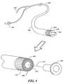
- Some of the ultrasonic imaging catheters currently in useare “side viewing” devices which produce B-mode images in a plane which is perpendicular to the longitudinal axis of the catheter and passes through the transducer. That plane can be referred to as the B-mode lateral plane and is illustrated in FIG. 1 .
- Other forward viewing devicesproduce a B-mode image in a plane that extends in a forward direction from the transducer and parallel to the axis of the catheter. That plane is referred to as the B-mode forward plane and is illustrated in FIG. 3 .
- the forward viewing devicesare particularly advantageous in that they allow the physician to see what is in front of the catheter, and they also allow imaging in areas which cannot be crossed with the catheter.
- FIGS. 1–3are isometric views showing different imaging planes generated by an ultrasonic catheter tip.
- FIG. 4is a drawing of one embodiment an ultrasonic imaging catheter with a guide wire and central distal lumen utilizing a ultrasonic transducer array assembly according to the present invention.
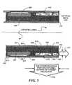
- FIG. 5is a side elevational view, partly broken away, showing one embodiment of an ultrasonic imaging catheter incorporating the invention.
- FIG. 6is an enlarged sectional view of one embodiment of an ultrasonic transducer element in accordance with the invention.
- FIG. 7is a side cross-sectional view of an alternate embodiment of a transducer element interconnection technique in accordance with the invention.
- FIG. 8is a diagram of an ultrasonic transducer array assembly shown during manufacturing in its flat state in accordance with the invention.
- FIG. 9shows a block diagram of an ultrasound system in accordance with the present invention.
- FIGS. 10–11are diagrams showing the orientation of one C-mode image vector and a description of the initialization of the element stepping around the array necessary for the assembly of the vector in the image.
- a catheter 400 for intravascular usehas an elongated flexible body 402 with an axially extending lumen 404 through which a guide wire 406 , fluids, and/or various therapeutic devices or other instruments can be passed.
- the inventionis not, however, limited to use with a catheter, and it can be utilized with any suitable catheter, guide wire, probe, etc.
- An ultrasonic imaging transducer assembly 408is provided at the distal end 410 of the catheter, with a connector 424 located at the proximal end of the catheter.
- This transducer 408comprises a plurality of transducer elements 412 that are preferably arranged in a cylindrical array centered about the longitudinal axis 414 of the catheter for transmitting and receiving ultrasonic energy.
- the transducer elements 412are mounted on the inner wall of a cylindrical substrate 416 which, in the embodiment illustrated, consists of a flexible circuit material that has been rolled into the form of a tube.
- the end portions 420 of the transducer elements 412are shown at the distal portion of the transducer assembly.
- a transducer backing material 422 with the proper acoustical propertiessurrounds the transducer elements 412 .
- An end cap 418which isolates the ends of the transducer elements, is attached to the transducer assembly.
- the end portions 420 of the transducer elements 412can be covered with nonconductive adhesive in order to insulate them from external fluids (e.g., blood).
- FIG. 5there is shown a cross-sectional view of the transducer assembly 408 cut in half and showing both sides.
- Integrated circuits 502 for interfacing with the transducer elementsare mounted on the substrate 416 and interconnections between the circuits 502 and the transducer elements are made by electrically conductive traces 508 and 522 on the surface of the substrate and buried within it.
- Conductive trace 508provides the “hot” conductor and interconnects the IC 502 to a transducer 412 .
- Conductive trace 522provides the ground conductor between the IC 502 and transducer 412 .
- Interconnection vias 516 , 518 and 524provide electrical connections between the conductive traces 508 , 510 and IC 502 and transducer element 512 .
- the transducer regionhas a central core that comprises a metal marker tube 504 and plastic members 506 and 418 , one acting as a lining 506 to the lumen, and the other one is the end-cap piece 422 that acts both to protect the end of the catheter and to act as a type of acoustic coupling enhancement for ultrasound transmission out the end of the array.
- an acoustic absorbing material 422Between the central core of the catheter and the peripherally arranged array elements there is an acoustic absorbing material 422 .
- the corehas a cylindrical body with an annular end wall at its distal end and an axially extending opening that is aligned with the lumen in the catheter.
- a sleeve of metal 504 or other suitable radiopaque materialis disposed coaxially about the core for use in locating the tip of the catheter within the body.
- Each of the transducer elements 412comprises an elongated body of PZT or other suitable piezoelectric material.
- the elementsextend longitudinally on the cylindrical substrate and parallel to the axis of the catheter.
- Each elementhas a rectangular cross-section, with a generally flat surface at the distal end thereof
- the transducer elementsare piezoelectrically poled in one direction along their entire length as highlighted.
- a transversely extending notch 520 of generally triangular cross-sectionis formed in each of the transducer elements.
- the notchopens through the inner surface of the transducer element and extends almost all the way through to the outer surface.
- the notch 520has a vertical sidewall on the distal side and an inclined sidewall on the proximal side.
- the vertical wallis perpendicular to the longitudinal axis of the catheter, and the inclined wall is inclined at an angle on the order of 60° to the axis.
- the notchwhich exists in all the array transducer elements, can be filled with a stable non-conductive material 526 .
- An example of a material that can be used to fill notch 520is a non-conductive epoxy having low acoustic impedance.
- conductive materials having low acoustic impedancemay also be used to fill notch 520 . If a conductive material is used as the notch filler, it could avoid having to metalize the top portion to interconnect both portions of the transducer elements as required if a nonconductive material is utilized. Conductive materials are not the preferred notch filler given that they have an affect on the E-fields generated by the transducer elements.
- the transducer arrayprovides for a forward looking elevation aperture for 10 mega Hertz (MHz) ultrasound transmit and receive 514 , and a side looking elevation aperture 512 for 20 MHz ultrasound transmit and receive.
- MHzmega Hertz
- the inner and outer surfaces of the transducer elementsare metallized to form electrodes 528 , 530 .
- a secondary metalizationis formed over the insulated notch area 520 to create a continuous electrical connection of the electrode 530 between its proximal and distal ends.
- Outer electrodeserves as a ground electrode 530 and is connected by means of metal via 518 to trace 522 , which is buried in the substrate.
- Inner electrode 528extends along the walls of notch 520 , wraps around the proximal end of the element and is connected directly to trace 508 on the surface of the substrate.
- the transducer metallizationconsists of a layer of gold over a layer of chrome, with the chrome serving as an adhesion layer for the gold. Those skilled in the art will realize that other metalization materials can be utilized.
- the transducer arrayis manufactured by electrically and mechanically bonding a poled, metallized block of the piezoelectric material 412 to the flexible circuit substrate 416 with the substrate in its unrolled or flat condition as shown in FIG. 8 .
- the transducer blockexists, as a piezoelectrically poled state where the thickness-axis poling is generally uniform in distribution and in the same axis throughout the entire block of material.
- Notch 520is then formed across the entire piezoelectric block, e.g. by cutting it with a dicing saw.
- Each of the individual notches 520is filled with a material 526 such as plastic and a metallization 804 is applied to the top of the notch to form a continuous transducer inner electrode with metallization 806 .
- the blockis then cut lengthwise to form the individual elements that are isolated from each other both electrically and mechanically, with kerfs 808 formed between the elements.
- Cable wire attachment terminals 802are provided on the substrate which allow microcables that are electrically connected to an external ultrasound system to connect with the transducer assembly in order to control the transducers.
- the integrated circuits 502are installed on the substrate 416 , and the substrate is then rolled into its cylindrical shape, with the transducer elements on the inner side of the cylinder.
- the sleeve of radiopaque materialis mounted on the core, the core is positioned within the cylinder, and the acoustic absorbing material is introduced into the volume between the core and the transducer elements. In the event that a radiopaque marker is not required for a particular application, it can be omitted.
- the transducer elements 412can be operated to preferentially transmit and receive ultrasonic energy in either a thickness extensional TE) mode (k 33 operation) or a length extensional (LE) mode (k 31 operation).
- the frequency of excitation for the TE modeis determined by the thickness of the transducer elements in the radial direction
- the frequency for the LE modeis determined by the length of the body between distal end surface 614 and the vertical wall 610 of notch 520 .
- the thickness TE modeis resonant at a frequency whose half wavelength in the piezoelectric material is equal to the thickness of the element.
- the LE modeis resonant at a frequency whose half wavelength in the piezoelectric material is equal to the distance between the distal end and the notch.
- Each transducer elementis capable of individually operating to transmit and receive ultrasound energy in either mode, with the selection of the desired mode (i.e. “side”, or “forward”) being dependent upon; a) an electronically selected frequency band of interest, b) a transducer design that spatially isolates the echo beam patterns between the two modes, and c) image plane specific beamforming weights and delays for a particular desired image plane to reconstruct using synthetic aperture beamforming techniques, where echo timing incoherence between the “side” and “forward” beam patterns will help maintain modal isolation.
- the distance 604 between the notch 520 which forms an acoustical discontinuity and the distal end of each transducer element, also referred to as the first portion of the transducer element,is made equal to approximately twice the thickness 608 of the element, resulting in a resonant frequency for the TE mode that is approximately twice the resonant frequency for the LE mode.
- the TE frequencyshould be at least 1.5 times the LE frequency, and preferably at least twice.
- the steep wall 610 or sharp cut on the distal side of the notchprovides an abrupt end to the acoustic transmission path in the piezoelectric material and facilitates a half wave resonant condition at the LE frequency of operation.
- the transducer element segment or second portion 606 which is between the notch 520 and the proximal end 612 of the elementwill also be able to resonate in an LE mode, but the design, through careful selection of this segment length, can be made to place this resonant frequency (and its harmonics) at a low (or high) enough frequency to create a reasonable modal dispersion characteristic.
- the LE mode acoustic coupling for this segment to the “end” of the arraywill also be quite poor, and aid in attenuating its undesired response.
- Any element in the arraycan also be selectively used as a receiver of ultrasonic energy in either the TE or the LE mode of operation by the ultrasound system that is connected to the ultrasound assembly.
- FIG. 7there is shown an alternate interconnection technique used to interconnect between the IC 502 and the individual transducer elements 412 .
- a solder or other conductive materialsuch as a metal-epoxy 702 is used to connect ground trace 510 with the ground electrode of the transducer element.
- An insulating separation layer 708 between the ground and “hot” electrodesis located at the proximal end of the transducer element 412 .
- epoxy insulation 704is used in order to connect the “hot” conductive trace or runner 508 to its corresponding electrode on the transducer element.
- the top of the epoxy insulationis then metallized 706 in order to electrically interconnect the trace or runner 508 to its corresponding electrode prior to dicing the transducer block into discrete elements.
- a piezoelectric transducerwhen properly excited, will perform a translation of electrical energy to mechanical energy, and as well, mechanical to electrical.
- the effectiveness of these translationsdepends largely on the fundamental transduction efficiency of the transducer assembly taken as a whole.
- the transduceris a three dimensional electro-mechanical device though, and as such is always capable of some degree of electro-mechanical coupling in all possible resonate modes, with one or several modes dominating.
- an imaging transducer designseeks to create a single dominate mode of electro-mechanical coupling, suppressing all other coupling modes as “spurious.”
- the common method used to accomplish a transducer design with a single dominate mode of electro-mechanical couplingusually rests in the creation of a single, efficient mechanical coupling “port” to the medium outside of the transducer.
- the single portis created by mounting the transducer such that the most efficient resonant mode of transducer operation faces that mechanical coupling port, with all other modes suppressed by means of mechanical dispersion attained by transducer dimensional control and dampening materials.
- the transducer designutilizes the fact that a transducer can be effective in two principal electro-mechanical coupling modes, each mode using a different frequency of operation, acoustic “port”, and electro-mechanical coupling efficiency.
- One portis the “side looking” port that is used in the cross-sectional view image as shown in FIG. 1 .
- the other portis the “end”, or, “forward looking” port of the array.
- the present inventionallows the two electro-mechanical coupling modes (i.e. “side” 512 and “forward” 514 ) to be always active, without any mechanical switching necessary to choose one mode exclusive of the other.
- the design of this inventionalso assures that echoes of any image target in the “side looking” plane (see FIG. 1 ) do not interfere with the target reconstruction in the “forward looking” planes (see FIGS. 2 and 3 ), and reciprocally, image targets from the “forward looking” do not interfere with the target reconstruction in the “side looking” planes.
- the design methods listed beloware used to maintain sufficient isolation between the two modes of operation.
- the “side looking” portis designed for approximately twice the frequency of the “forward looking” port in accordance with the preferred embodiment.
- the transducer dimensional designis such that the “high frequency and side looking” transducer port sensitivity to low frequency signals, and as well the “low frequency and forward looking” transducer port to high frequency signals, is very low.
- the transmit and receive acoustic “beam” directions of the two modes 512 and 514are at approximately right angles to each other and this feature offers an additional isolation with respect to image target identification.
- the echo collection process in “forward” beam reconstructionuses an intentional physical separation of transmitting and receiving transducer elements of preferably 10 elements or more in the circular array annulus. This physical separation aids in preventing “spurious” transmit echoes from the “high frequency side looking” port from contaminating the receiving element listening to “forward only” echoes at the its lower frequency of operation.
- the two modes of operationare operated at center frequencies that differ by about a factor of two.
- This design featureallows for additional isolation between the two modes through the use of band pass filters in the host system that is processing the echo signals received from the catheter. Additionally, if one or both of the two modes is operated in a low fractional bandwidth design (i.e. ⁇ 30%), the bandpass filters will be even more effective in the maintenance of very high modal isolation.
- Synthetic aperture beam reconstructionis used for all image modes.
- the beam formation processwill preferentially focus only on image targets that are coherently imaged in a particular image plane.
- image reconstructionis forming an image in, for example, the “side looking” plane
- targets that may have contaminated the echoes from the “forward looking” planeswill be generally incoherent and will be suppressed as a type of background noise.
- the reciprocalis also true: “side looking” echoes contaminants will be generally incoherent in “forward looking” imaging and will be suppressed through the process of synthetic aperture reconstruction.
- a flexible digital image reconstruction systemis required for the creation of multiple image planes on demand.
- the preferred method of assembling multiple image planesutilizes a synthetic aperture reconstruction approach.
- the “side looking” image shown in FIG. 1can be reconstructed using sampled transducer element apertures as large as for example 14 contiguous transducer elements in a 64 total transducer element circular array.
- the transmit-receive echo collection for aperture reconstructioncan be continuously shifted around the circular array, sampling all transmit-receive cross-product terms to be used in a particular aperture reconstruction.
- Within any 14-element aperturethere can be 105 independent transmit-receive echo cross products used to construct the image synthetically.
- “Forward looking” images shown in FIGS. 2 and 3can be reconstructed using sampled apertures that consist of selected transducer elements arranged on the annulus end of the circular array.
- all elementsmay contribute to a complete data set capture (this would consist of 64 by 32 independent transmit-receive element cross-products) to form a “forward looking” image in either C-mode or B-mode.
- a reduced number of independent transmit-receive element cross-productsare used to adequately formulate the image.
- the transmit-receive echo collection for aperture reconstructioncan be continuously shifted around the circular array, sampling all transmit-receive element cross-products to be used in a particular aperture reconstruction.
- Special signal processingmay be advantageous, especially in the “forward looking” imaging modes that use a less efficient transducer coupling coefficient (k 31 ) and as well may suffer from additional diffraction loss not experienced in the “side looking” mode of synthetic aperture imaging.
- a “forward looking” C-mode image planeas an example, a low noise bandwidth can be achieved by using a high number of transmit pulses and a narrow bandpass echo filter in the processing system.
- a matched filter implementation from the use of correlation processingmay be used to improve the echo signal-to-noise ratio.
- This cross-sectional B-mode operation of the catheter imaging deviceis in its ability to see an image at great depth in the radial dimension from the catheter, and at high image resolution. This depth of view can help aid the user of the catheter to position the device correctly prior to electronically switching to a “forward viewing” mode of operation.
- Image targets moving quickly in a path generally parallel to the long axis of the cathetercan be detected and displayed as a colored region in this mode; this information can be used to compare and confirm moving target information from the “forward viewing” mode of operation of the catheter to enhance the usefulness of the imaging tool.
- the transducer in this “primary” modeoperates in the thickness extensional (TE) resonance, utilizing the k 33 electro-mechanical coupling coefficient to describe the coupling efficiency.
- This “thickness resonance”refers to a quarter wave or half wave (depending on the acoustic impedance of the transducer backing formulation) resonance in the transducer dimension that is in alignment with the polarization direction of the transducer, and also the sensed or applied electric field.
- This TE modeutilizes a typically high frequency thickness resonance developed in the transducer short dimension following either electric field excitation to generate ultrasound acoustic transmit echoes, or, in reception mode following acoustic excitation to generate an electric field in the transducer.
- the TE modeis used for generating a cross-sectional B-mode image.
- This cross-section imagecuts through the array elements in an orthogonal plane to the long axis of the transducer elements. Echo information gathered from sequential transducer element sampling around the array allows for the synthetically derived apertures of various sizes around the array.
- a contiguous group of transducer elements in the arrayare sequentially used in a way to fully sample all the echo-independent transmit-receive element pairs from the aperture.
- This sequencing of elements to fully sample an apertureusually involves the transmission of echo information from one or more contiguous elements in the aperture and the reception of echo information on the same or other elements, proceeding until all the echo independent transmit-receive pairs are collected.
- the small notch ( 520 ) forming an acoustical discontinuity in the middle of the arraywill have a minor, but insignificant effect on the TE mode transmission or reception beam pattern for that element.
- the small notchwill be a non-active region for the TE mode resonance and therefore contribute to a “hole” in the very near field beam pattern for each element.
- the important beam characteristics however, such as the main lobe effective beam width and amplitude,will not be substantially effected, and except for a very minor rise in the transducer elevation side lobes, reasonable beam characteristics will be preserved as if the entire length of the transducer element was uniformly active.
- the TE mode transducer operationwill exist with other resonant modes simultaneously.
- the efficiency of electro-mechanical energy coupling however for each mode thoughdepends on primarily these factors: a) the k coefficient that describes the energy efficiency of transduction for a given resonance node, b) the acoustic coupling path to the desired insonification medium, and c) the echo transmission-reception signal bandwidth matching to the transducer resonance for that particular mode.
- a transducer designis created to optimize the factors above for only the TE resonance, while the other resonant modes within a transducer are to be ignored through the design which suppresses the undesired resonances by minimizing the energy coupling factors mentioned above.
- the proposed transducer designwhich features a high efficiency TE mode coupling for desired echoes and frequency dispersion of the unwanted resonances and echoes, along with the other modal isolation reasons stated in an earlier section, constitutes a means for high quality TE echo energy transduction for only those desired in-plane echoes used in the creation of the B-mode cross-sectional image plane.
- the host ultrasound processing system shown in FIG. 9controls the ultrasound array 408 element selection and stepping process whereby a single element 412 or multiple elements will transmit and the same or other elements will receive the return echo information.
- the elements in the array that participate in a given aperturewill be sampled sequentially so that all essential cross product transmit-receive terms needed in the beam forming sum are obtained.
- the host processing system or computer 914 and reconstruction controller 918will control the transmit pulse timing provided to wideband pulser/receiver 902 , the use of any matched filter 910 via control line 916 to perform echo pulse compression.
- the echo band pass filter (BPF) processing paths in the systemare selected using control signal 906 to select between either the 10 MHz 904 or 20 MHz 936 center frequency BPF paths.
- the amplified and processed analog echo informationis digitized using ADC 908 with enough bits to preserve the dynamic range of the echo signals, and passed to the beamformer processing section via signal 912 .
- the beam former section under the control of reconstruction controller 918uses stored echo data from all the transmit-receive element pairs that exist in an aperture of interest.
- All element group aperturesare “reconstructed” using well known synthetic aperture reconstruction techniques to form beamformed vectors of weighted and summed echo data that radially emanate from the catheter surface using beamformer memory array 922 , devices 924 and summation unit 926 .
- Memory control signal 920controls switch bank 924 which selects which memory array to store the incoming data.
- the vector echo datais processed through envelope detection of the echo data and rejection of the RF carrier using vector processor 928 . Finally a process of coordinate conversion is done to map the radial vector lines of echo data to raster scan data using scan converter 930 for video display using display 932 .
- This processing systemmay also accomplish a blood velocity detection by tracking the blood cells through the elevation length of the transducer beams.
- the tracking schemeinvolves a modification of the element echo sampling sequencing and the use of the beamformer section of the host processing system.
- the blood velocity informationmay be displayed as a color on the video display; this blood velocity color information is superimposed on the image display to allow the user to see simultaneous anatomical information and blood movement information.
- a “forward” C-mode planeproduces a cross-sectional view similar to the standard B-mode cross-sectional view, and so can offer comparable image interpretation for the user, and as well this forward image plane is made more useful because the user can see the presence of image targets at the center of the image, otherwise obscured in the standard cross-sectional view by the catheter itself.
- This forward viewallows also the ideal acoustic beam positioning for the detection and color image display of Doppler echo signals from targets moving generally in parallel with the long axis of the catheter device.
- the transducer in this “secondary” modeoperates in the length extensional (LE) resonance, utilizing the k 31 electro-mechanical coupling coefficient to describe the coupling efficiency.
- the poling direction of the transducer element and the sensed or applied electric field in the transducerare in alignment, but the acoustic resonance is at 90 degrees to the electric field and poling direction.
- This “length resonance”refers fundamentally to a half wave resonance in the transducer element's length dimension that is at 90 degrees with the polarization direction of the transducer.
- the LE mode of resonancewhich is typically much lower in resonant frequency than the TE mode because the element length is normally much longer than the thickness dimension, always exists to some extent in a typical transducer array element, but is usually suppressed through a frequency dispersive design.
- the preferred embodiment of the present inventionutilizes an abrupt physical discontinuity (a notch 520 ) in the transducer element to allow a half wave LE resonance to manifest itself at a desired frequency, in the case of the preferred embodiment, at about one half the frequency of the TE mode resonance.
- a unique feature of this inventionis a mechanically fixed transducer design that allows two resonant modes to operate at reasonably high efficiencies, while the “selection” of a desired mode (i.e.
- sideis a function of a) an electronically selected frequency band of interest, b) a transducer design that spatially isolates the echo beam patterns between the two modes, and c) image plane specific beamforming weights and delays for a particular desired image plane to reconstruct using synthetic aperture beamforming techniques, where echo timing incoherence between the “side” and “forward” beam patterns will help maintain modal isolation.
- a resonant mode in a transducer designcan be made efficient in electro-mechanical energy coupling if at least the three fundamental factors effecting coupling merit are optimized, namely a) the k coefficient (in this case it is the k 31 electro-mechanical coupling coefficient) that describes the energy efficiency of transduction for a given resonance node, b) the acoustic coupling path to the desired insonification medium, and c) the echo transmission-reception signal bandwidth matching to the transducer resonance for that particular mode.
- the inventionallows for reasonable optimization of these factors for the LE mode of resonance, although the LE mode coupling efficiency is lower than that of the TE mode coupling.
- the k 31 coupling factor, used in describing LE mode efficiencyis typically one half that of k 33 , the coupling factor that describes the TE mode efficiency.
- the abrupt acoustical discontinuity in the transducer elementis created at a step in the assembly of the array.
- a dicing saw cutcan be made the entire length of the transducer material block, creating the notch.
- the notch depthshould be deep enough in the transducer material to create an abrupt discontinuity in the distal portion of the transducer material to allow for a high efficiency LE mode half wave resonance to exist in this end of the transducer element.
- the saw cutshould not be so deep as to sever the ground electrode trace on the transducer block side bonded to the flex circuit.
- the cutshould ideally have a taper on the proximal side to allow for acoustically emitted energy to be reflected up into the backing material area and become absorbed.
- the distal transducer region LE mode half wave resonancewill exist at 10 MHz in PZT (Motorola 3203HD) for a length of about 170 microns between the distal end of the transducer element and the notch.
- the proximal transducer region LE mode resonancewill exist at a frequency considered out of band (approximately 6 MHz) in the two embodiments shown in FIGS. 5 and 7 so as to minimally interfere with the desired operating frequencies (in this case 10 MHz LE mode resonance in the distal region for “forward” acoustic propagation, and 20 MHz TE mode resonance in the entire active field length of the transducer).
- the desired acoustic energy coupling port of the distal transducer LE resonant mode regionis at the distal end of the catheter array.
- an end cap made of polyurethanecould be used, or alternatively, a uniform coating of adhesive material would suffice.
- the beam pattern produced by this acoustic portmust be broad enough to insonify a large area that covers intended extent of the image plane to be formed. To this end, the beam pattern must typically be at least 60 degrees wide as a “cone shaped” beam measured in the plane to be formed at the half-maximum intensity angles for 2-way (transmitted and received) echoes.
- the preferred design of the arrayhas 64 or more elements, and a transducer sawing pitch equal to pi times the catheter array diameter divided by the number of elements in the array.
- the pitchis 0.055 mm.
- Using two consecutive array elements as a “single” effective LE mode acoustic portcan provide an adequate, uniform beam pattern that produces the required 60-degree full-width half maximum (“FWHM”) figure of merit.
- the aperture of this “single” forward looking portis then approximately 0.080 mm by 0.085 mm (where 0.085 mm is twice the pitch dimension minus the kerf width of 0.025 mm).
- the transducer designmay also include a version where no notch is needed in the transducer block.
- the driven electrodecan exist all along one surface of the transducer element, and the ground or reference electrode can exist all along the opposite side of the element.
- the long axis length of the transducerwill resonate at a half wavelength in LE mode, and the thickness dimension will allow the production of a TE mode resonance in that thickness dimension.
- the LE and TE mode resonant frequencieswill be quite different in order to maintain the proper TE mode elevation beam focus.
- the element lengthshould be approximately 0.5 mm long.
- the resulting half wave resonance frequency in LE modethen will be about 3 MHz.
- This designcan be used for dual-mode imaging, but will not offer the focusing benefits that 10 MHz imaging can offer for the forward looking image planes.
- Other designsare possible, where the forward frequency is maintained near 10 MHz, but the required frequency for the side-looking mode will rise dramatically, and although this can be useful in itself, will complicate the design by requiring a concomitant increase in the number of elements and/or a reduction in the array element pitch dimension.
- the host processing systemwill control the array element selection and stepping process whereby one element, a two element pair, or other multiple elements in combination, will transmit and the same or other elements will receive the return echo information.
- the intended array operational modeis the LE resonant mode to send and receive echo information in a forward direction from the end of the catheter array.
- the LE mode echoes producedmay be isolated from the TE mode echoes through primarily frequency band limitations (both by transducer structural design and by electrical band selection filters), and through the beamforming reconstruction process itself as a kind of echo selection filter.
- the entire array diameterwill be used as the maximum aperture dimension. This means that, in general, element echo sampling will take place at element locations throughout the whole array in preferably a sparse sampling mode of operation to gather the necessary minimum number of cross-product echoes needed to create image resolution of high quality everywhere in the reconstructed plane.
- the FWHM main beam resolutionwill be close to the 20 MHz resolution of the “side looking” cross-sectional image. This is due to the fact that although the “forward looking” echo frequency is about one half as much as the “side looking” frequency, the usable aperture for the forward looking mode is about 1.6 times that of the largest side looking aperture (i.e. the largest side looking aperture is about 0.7 mm, and the forward aperture is about 1.15 mm). For a 10 MHz forward looking design, the FWHM main lobe resolution in an image plane reconstructed at a depth of 3 mm will be approximately 0.39 mm, and 0.65 mm resolution at 5 mm distance.
- a “complete data set”e.g. 64 ⁇ 32
- a sparse samplinge.g. less than 64 ⁇ 32
- the C-mode image diameter that can be reconstructed and displayed with a high level of resolution from echo contributions throughout the whole arraywill be related to the distance between the reconstructed C-mode image plane and the distal end of the catheter.
- the C-mode image diameterwill be about 2.3 mm, at 5 mm distance the image diameter will be 4.6 mm, and at 7 mm distance the image diameter will be 6.9 mm.
- the host processing systemin addition to the control of the transducer element selection and stepping around the array, will control the transmit pulse timing, the use of any matched filter to perform echo pulse compression, and the echo band pass filter processing path in the system.
- the amplified and processed analog echo informationis digitized with enough bits to preserve the dynamic range of the echo signals, and passed to the beamformer processing section.
- the beam former sectionuses stored echo data from the sparse array sampling (or alternatively the whole complete array echo data set of 64 ⁇ 32 of transmit-receive element pairs) that exist in an aperture of interest. As the element echo sampling continues sequentially around the circular array 1108 as shown in FIGS.
- FIG. 11view “A” 1004 of FIG. 10 is shown which is a superposition of the distal catheter array and the forward looking image.
- Transducer elements # 1 and # 2 shown as item 1102show the start location for the transmit (Tx) transducer elements.
- Transducer elements # 12 and # 13 shown as item 1106is the start location for the Rx transducer elements.
- the steppingcontinues by stepping the Rx back around after the Tx has been incremented in the same “rotate” direction.
- Tx-Rx termsare collected.
- the vector echo datais processed through envelope detection of the echo data and rejection of the RF carrier. Finally a process of coordinate conversion is done to map the radial vector lines of echo data to raster scan data for video display.
- This processing systemmay also accomplish “forward looking” target (such as blood cells) velocity detection by either correlation-tracking the targets along the “forward looking” direction (with processing as earlier discussed with the “side looking” approach), or by standard Doppler processing of echo frequency shifts that correspond to target movement in directions parallel with the “forward looking” echo paths.
- the target (e.g. blood) velocity informationmay be displayed as a color on the video display; this velocity color information is superimposed on the image display to allow the user to see simultaneous anatomical information and target movement information.
- “Forward” B-mode plane imagingproduces a cross-sectional planar “sector” view (see FIG. 3 ) that can exist in any plane parallel to the catheter central axis and distal to the end of the catheter array.
- This imaging modemay be used, in addition, to produce image “sector” views that are tilted slightly out of plane (see FIG. 3 ), and as well, may produce individual or sets of image “sectors” rotated generally about the catheter axis to allow the user to see a multitude of forward image slices in a format that shows clearly the multidimensional aspects of the forward target region of interest.
- This forward B-mode imaging(as with C-mode plane imaging) utilizes the ideal acoustic beam positioning for the detection and color image display of Doppler echo signals from targets moving generally in parallel with the long axis of the catheter device.
- the transducer operation in creating the “forward looking” B-mode image formatis virtually the same as discussed earlier for creating the “forward looking” C-mode image.
- the transducer in this “secondary” modeoperates in the length extensional (LE) resonance, utilizing the k 31 electro-mechanical coupling coefficient to describe the coupling efficiency.
- Llength extensional
- the number of elements used at any time to form a wide beam pointing in the “forward” directionare selected to produce a required 60 degree FWHM beam width performance; the modal isolation techniques mentioned earlier against the higher frequency TE resonances are valid as well for this forward B-mode imaging method.
- the “forward” C-mode imagingwith high bandwidth echo signals (low bandwidth echo signals can also be used, but with some minor loss in image resolution)
- the lateral resolution in the “forward” B-mode imageis determined (as the C-mode image plane resolution) by the aperture (diameter of the array) used for the image reconstruction. The lateral resolution performance will be as stated earlier (i.e. from the description of the C-mode imaging case) for various depths from the catheter distal end.
- the host processing system as shown in FIG. 9will control the array element selection and stepping process whereby one element, a two element pair, or other multiple elements in combination, will transmit and the same or other elements will receive the return echo information.
- the intended array operational modeis the LE resonant mode to send and receive echo information in a forward direction from the end of the catheter array.
- the LE mode echoes producedmay be isolated from the TE mode echoes through primarily frequency band limitations (both by transducer structural design and by electrical band selection filters), and through the beamforming reconstruction process itself as a kind of echo selection filter.
- the entire array diameterwill be used as the maximum aperture dimension.
- element echo samplingwill take place at element locations throughout the whole array in preferably a sparse sampling mode of operation to gather the necessary minimum number of cross-product echoes needed to create image resolution of high quality everywhere in the reconstructed plane.
- transmit-receive echo contributions collected from elements throughout the whole catheter arrayusing either a “complete data set” (e.g. 64 ⁇ 32), or a sparse sampling (e.g.
- the FWHM main beam lateral resolution in the B-mode planewill be close to the 20 MHz resolution of the “side looking” cross-sectional image.
- the FW main lobe lateral resolution in the image plane reconstructed at a depth of 3 mmwill be approximately 0.39 mm, and 0.65 mm resolution at 5 mm distance.
- the B-mode sector image width that can be reconstructed and displayed with a high level of resolution from echo contributions throughout the whole arraywill be related to the distance between the reconstructed B-mode target depth in the image sector and the distal end of the catheter.
- the B-mode image sector widthwill be about 2.3 mm, at 5 mm distance the image sector width will be 4.6 mm, and at 7 mm distance the image sector width will be 6.9 mm.
- the host processing systemin addition to the control of the transducer element selection and stepping around the array, will control the transmit pulse timing, the use of any matched filter to perform echo pulse compression, and the echo band pass filter processing path in the system.
- the amplified and processed analog echo informationis digitized with enough bits to preserve the dynamic range of the echo signals, and passed to the beamformer processing section.
- the beam former sectionuses stored echo data from the sparse array sampling (or alternatively the whole complete array echo data-set of 64 ⁇ 32 of transmit-receive element pairs) that exist in an aperture of interest.
- the method used for the creation of a single “forward looking” sagittal B-mode image planemay be expanded to create multiple rotated sagittal planes around an axis either congruent with the catheter central axis, or itself slightly tilted off the catheter central axis. If enough rotated planes are collected, the beamforming system could then possess a capability to construct and display arbitrary oblique “slices” through this multidimensional volume, with B-mode or C-mode visualization in either a 2-D sector format, a 2-D circular format, or, other multidimensional formats.
- the echo data volumemay also be off-loaded to a conventional 3-D graphics engine that could create the desired image format and feature rendering that would enable improved visualization.
- the vector echo datais processed through envelope detection of the echo data and rejection of the RF carrier. Finally a process of coordinate conversion is done to map the radial vector lines of echo data to a video sector-format display of the “forward looking” B-mode image.
- This processing systemmay also accomplish “forward looking” target (such as blood cells) velocity detection by either correlation-tracking the targets along the “forward looking” direction (with processing as earlier discussed with the “side looking” approach), or by standard Doppler processing of echo frequency shifts that correspond to target movement in directions parallel with the “forward looking” echo paths in the “forward looking” B-mode plane.
- the target (e.g. blood) velocity informationmay be displayed as a color on the video display; this velocity color information is superimposed on the image display to allow the user to see simultaneous anatomical information and target movement information.
- the inventionhas a number of important features and advantages. It provides an ultrasonic imaging transducer and method that can be used for imaging tissue in multiple planes without any moving parts. It can operate in both forward and side imaging modes, and it permits imaging to be done while procedures are being carried out. Thus, for example, it can operate in a forward looking C-mode, while at the same time a therapeutic device such as a laser fiber-bundle can be used to treat tissue (e.g. an uncrossable arterial occlusion) ahead of the catheter tip either by tissue ablation, or, tissue photochemotherapy.
- the laser pulsesmay be timed with the ultrasound transmit-receive process so that the high frequency laser induced tissue reverberations can be seen in the ultrasound image plane simultaneously. In this way the invention can dynamically guide the operator's vision during a microsurgical procedure.
- the present inventioncan also be used in a biopsy or atherectomy procedure to allow the operator to perform a tissue identification prior to tissue excision; the advantage being that the catheter or biopsy probe device can be literally pointing in the general direction of the target tissue and thus aid significantly in the stereotaxic orientation necessary to excise the proper tissue sample.
- the inventioncan also be used for the proper positioning of a radiotherapy core wire in the treatment of target tissue that exists well beyond the distal extent of the catheter.
Landscapes
- Health & Medical Sciences (AREA)
- Life Sciences & Earth Sciences (AREA)
- Engineering & Computer Science (AREA)
- Heart & Thoracic Surgery (AREA)
- Molecular Biology (AREA)
- Biophysics (AREA)
- Nuclear Medicine, Radiotherapy & Molecular Imaging (AREA)
- Pathology (AREA)
- Radiology & Medical Imaging (AREA)
- Biomedical Technology (AREA)
- Veterinary Medicine (AREA)
- Medical Informatics (AREA)
- Physics & Mathematics (AREA)
- Surgery (AREA)
- Animal Behavior & Ethology (AREA)
- General Health & Medical Sciences (AREA)
- Public Health (AREA)
- Mechanical Engineering (AREA)
- Gynecology & Obstetrics (AREA)
- Ultra Sonic Daignosis Equipment (AREA)
- Transducers For Ultrasonic Waves (AREA)
- Apparatuses For Generation Of Mechanical Vibrations (AREA)
Abstract
Description
Claims (19)
Priority Applications (1)
| Application Number | Priority Date | Filing Date | Title |
|---|---|---|---|
| US10/243,823US7736317B2 (en) | 2000-02-09 | 2002-09-13 | Method and apparatus for delivering therapy in and association with an intravascular ultrasound device |
Applications Claiming Priority (3)
| Application Number | Priority Date | Filing Date | Title |
|---|---|---|---|
| US09/501,106US6457365B1 (en) | 2000-02-09 | 2000-02-09 | Method and apparatus for ultrasonic imaging |
| US10/174,412US6780157B2 (en) | 2000-02-09 | 2002-06-18 | Method and apparatus for ultrasonic imaging |
| US10/243,823US7736317B2 (en) | 2000-02-09 | 2002-09-13 | Method and apparatus for delivering therapy in and association with an intravascular ultrasound device |
Related Parent Applications (1)
| Application Number | Title | Priority Date | Filing Date |
|---|---|---|---|
| US10/174,412ContinuationUS6780157B2 (en) | 2000-02-09 | 2002-06-18 | Method and apparatus for ultrasonic imaging |
Publications (2)
| Publication Number | Publication Date |
|---|---|
| US20030015037A1 US20030015037A1 (en) | 2003-01-23 |
| US7736317B2true US7736317B2 (en) | 2010-06-15 |
Family
ID=23992162
Family Applications (3)
| Application Number | Title | Priority Date | Filing Date |
|---|---|---|---|
| US09/501,106Expired - LifetimeUS6457365B1 (en) | 2000-02-09 | 2000-02-09 | Method and apparatus for ultrasonic imaging |
| US10/174,412Expired - LifetimeUS6780157B2 (en) | 2000-02-09 | 2002-06-18 | Method and apparatus for ultrasonic imaging |
| US10/243,823Expired - Fee RelatedUS7736317B2 (en) | 2000-02-09 | 2002-09-13 | Method and apparatus for delivering therapy in and association with an intravascular ultrasound device |
Family Applications Before (2)
| Application Number | Title | Priority Date | Filing Date |
|---|---|---|---|
| US09/501,106Expired - LifetimeUS6457365B1 (en) | 2000-02-09 | 2000-02-09 | Method and apparatus for ultrasonic imaging |
| US10/174,412Expired - LifetimeUS6780157B2 (en) | 2000-02-09 | 2002-06-18 | Method and apparatus for ultrasonic imaging |
Country Status (6)
| Country | Link |
|---|---|
| US (3) | US6457365B1 (en) |
| EP (1) | EP1261436A1 (en) |
| JP (1) | JP4612263B2 (en) |
| AU (1) | AU2001236717A1 (en) |
| CA (1) | CA2395631A1 (en) |
| WO (1) | WO2001058601A1 (en) |
Cited By (153)
| Publication number | Priority date | Publication date | Assignee | Title |
|---|---|---|---|---|
| US20120095335A1 (en)* | 2010-10-18 | 2012-04-19 | CardioSonic Ltd. | Ultrasound transducer and uses thereof |
| WO2014100397A1 (en) | 2012-12-21 | 2014-06-26 | Jason Spencer | Catheter orienting markers |
| US8880185B2 (en) | 2010-06-11 | 2014-11-04 | Boston Scientific Scimed, Inc. | Renal denervation and stimulation employing wireless vascular energy transfer arrangement |
| US8939970B2 (en) | 2004-09-10 | 2015-01-27 | Vessix Vascular, Inc. | Tuned RF energy and electrical tissue characterization for selective treatment of target tissues |
| US8951251B2 (en) | 2011-11-08 | 2015-02-10 | Boston Scientific Scimed, Inc. | Ostial renal nerve ablation |
| US8974451B2 (en) | 2010-10-25 | 2015-03-10 | Boston Scientific Scimed, Inc. | Renal nerve ablation using conductive fluid jet and RF energy |
| US9023034B2 (en) | 2010-11-22 | 2015-05-05 | Boston Scientific Scimed, Inc. | Renal ablation electrode with force-activatable conduction apparatus |
| US9028417B2 (en) | 2010-10-18 | 2015-05-12 | CardioSonic Ltd. | Ultrasound emission element |
| US9028472B2 (en) | 2011-12-23 | 2015-05-12 | Vessix Vascular, Inc. | Methods and apparatuses for remodeling tissue of or adjacent to a body passage |
| US9028485B2 (en) | 2010-11-15 | 2015-05-12 | Boston Scientific Scimed, Inc. | Self-expanding cooling electrode for renal nerve ablation |
| US9050106B2 (en) | 2011-12-29 | 2015-06-09 | Boston Scientific Scimed, Inc. | Off-wall electrode device and methods for nerve modulation |
| US9060761B2 (en) | 2010-11-18 | 2015-06-23 | Boston Scientific Scime, Inc. | Catheter-focused magnetic field induced renal nerve ablation |
| US9079000B2 (en) | 2011-10-18 | 2015-07-14 | Boston Scientific Scimed, Inc. | Integrated crossing balloon catheter |
| WO2014099797A3 (en)* | 2012-12-20 | 2015-07-16 | Jeremy Stigall | Catheter assembly with a shortened tip |
| US9084609B2 (en) | 2010-07-30 | 2015-07-21 | Boston Scientific Scime, Inc. | Spiral balloon catheter for renal nerve ablation |
| WO2015108941A1 (en) | 2014-01-14 | 2015-07-23 | Volcano Corporation | Devices and methods for forming vascular access |
| US9089350B2 (en) | 2010-11-16 | 2015-07-28 | Boston Scientific Scimed, Inc. | Renal denervation catheter with RF electrode and integral contrast dye injection arrangement |
| US9119600B2 (en) | 2011-11-15 | 2015-09-01 | Boston Scientific Scimed, Inc. | Device and methods for renal nerve modulation monitoring |
| US9119632B2 (en) | 2011-11-21 | 2015-09-01 | Boston Scientific Scimed, Inc. | Deflectable renal nerve ablation catheter |
| US9125667B2 (en) | 2004-09-10 | 2015-09-08 | Vessix Vascular, Inc. | System for inducing desirable temperature effects on body tissue |
| US9125666B2 (en) | 2003-09-12 | 2015-09-08 | Vessix Vascular, Inc. | Selectable eccentric remodeling and/or ablation of atherosclerotic material |
| US9155589B2 (en) | 2010-07-30 | 2015-10-13 | Boston Scientific Scimed, Inc. | Sequential activation RF electrode set for renal nerve ablation |
| US9162046B2 (en) | 2011-10-18 | 2015-10-20 | Boston Scientific Scimed, Inc. | Deflectable medical devices |
| US9173696B2 (en) | 2012-09-17 | 2015-11-03 | Boston Scientific Scimed, Inc. | Self-positioning electrode system and method for renal nerve modulation |
| US9186209B2 (en) | 2011-07-22 | 2015-11-17 | Boston Scientific Scimed, Inc. | Nerve modulation system having helical guide |
| US9186210B2 (en) | 2011-10-10 | 2015-11-17 | Boston Scientific Scimed, Inc. | Medical devices including ablation electrodes |
| US9192790B2 (en) | 2010-04-14 | 2015-11-24 | Boston Scientific Scimed, Inc. | Focused ultrasonic renal denervation |
| US9192435B2 (en) | 2010-11-22 | 2015-11-24 | Boston Scientific Scimed, Inc. | Renal denervation catheter with cooled RF electrode |
| US9220558B2 (en) | 2010-10-27 | 2015-12-29 | Boston Scientific Scimed, Inc. | RF renal denervation catheter with multiple independent electrodes |
| US9220561B2 (en) | 2011-01-19 | 2015-12-29 | Boston Scientific Scimed, Inc. | Guide-compatible large-electrode catheter for renal nerve ablation with reduced arterial injury |
| US9265969B2 (en) | 2011-12-21 | 2016-02-23 | Cardiac Pacemakers, Inc. | Methods for modulating cell function |
| US9277955B2 (en) | 2010-04-09 | 2016-03-08 | Vessix Vascular, Inc. | Power generating and control apparatus for the treatment of tissue |
| US9283033B2 (en) | 2012-06-30 | 2016-03-15 | Cibiem, Inc. | Carotid body ablation via directed energy |
| US9286673B2 (en) | 2012-10-05 | 2016-03-15 | Volcano Corporation | Systems for correcting distortions in a medical image and methods of use thereof |
| US9292918B2 (en) | 2012-10-05 | 2016-03-22 | Volcano Corporation | Methods and systems for transforming luminal images |
| US9297845B2 (en) | 2013-03-15 | 2016-03-29 | Boston Scientific Scimed, Inc. | Medical devices and methods for treatment of hypertension that utilize impedance compensation |
| US9295447B2 (en) | 2011-08-17 | 2016-03-29 | Volcano Corporation | Systems and methods for identifying vascular borders |
| US9301687B2 (en) | 2013-03-13 | 2016-04-05 | Volcano Corporation | System and method for OCT depth calibration |
| US9307926B2 (en) | 2012-10-05 | 2016-04-12 | Volcano Corporation | Automatic stent detection |
| US9324141B2 (en) | 2012-10-05 | 2016-04-26 | Volcano Corporation | Removal of A-scan streaking artifact |
| US9327100B2 (en) | 2008-11-14 | 2016-05-03 | Vessix Vascular, Inc. | Selective drug delivery in a lumen |
| US9326751B2 (en) | 2010-11-17 | 2016-05-03 | Boston Scientific Scimed, Inc. | Catheter guidance of external energy for renal denervation |
| US9360630B2 (en) | 2011-08-31 | 2016-06-07 | Volcano Corporation | Optical-electrical rotary joint and methods of use |
| US9358365B2 (en) | 2010-07-30 | 2016-06-07 | Boston Scientific Scimed, Inc. | Precision electrode movement control for renal nerve ablation |
| US9364284B2 (en) | 2011-10-12 | 2016-06-14 | Boston Scientific Scimed, Inc. | Method of making an off-wall spacer cage |
| US9367965B2 (en) | 2012-10-05 | 2016-06-14 | Volcano Corporation | Systems and methods for generating images of tissue |
| US9383263B2 (en) | 2012-12-21 | 2016-07-05 | Volcano Corporation | Systems and methods for narrowing a wavelength emission of light |
| US9408661B2 (en) | 2010-07-30 | 2016-08-09 | Patrick A. Haverkost | RF electrodes on multiple flexible wires for renal nerve ablation |
| US9420955B2 (en) | 2011-10-11 | 2016-08-23 | Boston Scientific Scimed, Inc. | Intravascular temperature monitoring system and method |
| US9433760B2 (en) | 2011-12-28 | 2016-09-06 | Boston Scientific Scimed, Inc. | Device and methods for nerve modulation using a novel ablation catheter with polymeric ablative elements |
| US9463062B2 (en) | 2010-07-30 | 2016-10-11 | Boston Scientific Scimed, Inc. | Cooled conductive balloon RF catheter for renal nerve ablation |
| US9478940B2 (en) | 2012-10-05 | 2016-10-25 | Volcano Corporation | Systems and methods for amplifying light |
| US9486143B2 (en) | 2012-12-21 | 2016-11-08 | Volcano Corporation | Intravascular forward imaging device |
| US9486355B2 (en) | 2005-05-03 | 2016-11-08 | Vessix Vascular, Inc. | Selective accumulation of energy with or without knowledge of tissue topography |
| US9486270B2 (en) | 2002-04-08 | 2016-11-08 | Medtronic Ardian Luxembourg S.A.R.L. | Methods and apparatus for bilateral renal neuromodulation |
| US9566456B2 (en) | 2010-10-18 | 2017-02-14 | CardioSonic Ltd. | Ultrasound transceiver and cooling thereof |
| US9579030B2 (en) | 2011-07-20 | 2017-02-28 | Boston Scientific Scimed, Inc. | Percutaneous devices and methods to visualize, target and ablate nerves |
| US9596993B2 (en) | 2007-07-12 | 2017-03-21 | Volcano Corporation | Automatic calibration systems and methods of use |
| US9612105B2 (en) | 2012-12-21 | 2017-04-04 | Volcano Corporation | Polarization sensitive optical coherence tomography system |
| US9622706B2 (en) | 2007-07-12 | 2017-04-18 | Volcano Corporation | Catheter for in vivo imaging |
| US9649156B2 (en) | 2010-12-15 | 2017-05-16 | Boston Scientific Scimed, Inc. | Bipolar off-wall electrode device for renal nerve ablation |
| US9668811B2 (en) | 2010-11-16 | 2017-06-06 | Boston Scientific Scimed, Inc. | Minimally invasive access for renal nerve ablation |
| US9687166B2 (en) | 2013-10-14 | 2017-06-27 | Boston Scientific Scimed, Inc. | High resolution cardiac mapping electrode array catheter |
| US9693821B2 (en) | 2013-03-11 | 2017-07-04 | Boston Scientific Scimed, Inc. | Medical devices for modulating nerves |
| US9709379B2 (en) | 2012-12-20 | 2017-07-18 | Volcano Corporation | Optical coherence tomography system that is reconfigurable between different imaging modes |
| US9707036B2 (en) | 2013-06-25 | 2017-07-18 | Boston Scientific Scimed, Inc. | Devices and methods for nerve modulation using localized indifferent electrodes |
| US9713730B2 (en) | 2004-09-10 | 2017-07-25 | Boston Scientific Scimed, Inc. | Apparatus and method for treatment of in-stent restenosis |
| US9730613B2 (en) | 2012-12-20 | 2017-08-15 | Volcano Corporation | Locating intravascular images |
| US9770172B2 (en) | 2013-03-07 | 2017-09-26 | Volcano Corporation | Multimodal segmentation in intravascular images |
| US9770606B2 (en) | 2013-10-15 | 2017-09-26 | Boston Scientific Scimed, Inc. | Ultrasound ablation catheter with cooling infusion and centering basket |
| US9808311B2 (en) | 2013-03-13 | 2017-11-07 | Boston Scientific Scimed, Inc. | Deflectable medical devices |
| US9808300B2 (en) | 2006-05-02 | 2017-11-07 | Boston Scientific Scimed, Inc. | Control of arterial smooth muscle tone |
| WO2017198800A1 (en) | 2016-05-20 | 2017-11-23 | Koninklijke Philips N.V. | Devices and methods for stratification of patients for renal denervation based on intravascular pressure and cross-sectional lumen measurements |
| US9827039B2 (en) | 2013-03-15 | 2017-11-28 | Boston Scientific Scimed, Inc. | Methods and apparatuses for remodeling tissue of or adjacent to a body passage |
| US9833283B2 (en) | 2013-07-01 | 2017-12-05 | Boston Scientific Scimed, Inc. | Medical devices for renal nerve ablation |
| US9858668B2 (en) | 2012-10-05 | 2018-01-02 | Volcano Corporation | Guidewire artifact removal in images |
| US9867530B2 (en) | 2006-08-14 | 2018-01-16 | Volcano Corporation | Telescopic side port catheter device with imaging system and method for accessing side branch occlusions |
| US9895194B2 (en) | 2013-09-04 | 2018-02-20 | Boston Scientific Scimed, Inc. | Radio frequency (RF) balloon catheter having flushing and cooling capability |
| US9907609B2 (en) | 2014-02-04 | 2018-03-06 | Boston Scientific Scimed, Inc. | Alternative placement of thermal sensors on bipolar electrode |
| US9925001B2 (en) | 2013-07-19 | 2018-03-27 | Boston Scientific Scimed, Inc. | Spiral bipolar electrode renal denervation balloon |
| US9943365B2 (en) | 2013-06-21 | 2018-04-17 | Boston Scientific Scimed, Inc. | Renal denervation balloon catheter with ride along electrode support |
| US9955946B2 (en) | 2014-03-12 | 2018-05-01 | Cibiem, Inc. | Carotid body ablation with a transvenous ultrasound imaging and ablation catheter |
| US9956033B2 (en) | 2013-03-11 | 2018-05-01 | Boston Scientific Scimed, Inc. | Medical devices for modulating nerves |
| US9962223B2 (en) | 2013-10-15 | 2018-05-08 | Boston Scientific Scimed, Inc. | Medical device balloon |
| US9974607B2 (en) | 2006-10-18 | 2018-05-22 | Vessix Vascular, Inc. | Inducing desirable temperature effects on body tissue |
| US10022182B2 (en) | 2013-06-21 | 2018-07-17 | Boston Scientific Scimed, Inc. | Medical devices for renal nerve ablation having rotatable shafts |
| US10058284B2 (en) | 2012-12-21 | 2018-08-28 | Volcano Corporation | Simultaneous imaging, monitoring, and therapy |
| US10070827B2 (en) | 2012-10-05 | 2018-09-11 | Volcano Corporation | Automatic image playback |
| US10085799B2 (en) | 2011-10-11 | 2018-10-02 | Boston Scientific Scimed, Inc. | Off-wall electrode device and methods for nerve modulation |
| US10166003B2 (en) | 2012-12-21 | 2019-01-01 | Volcano Corporation | Ultrasound imaging with variable line density |
| US10191220B2 (en) | 2012-12-21 | 2019-01-29 | Volcano Corporation | Power-efficient optical circuit |
| US10219780B2 (en) | 2007-07-12 | 2019-03-05 | Volcano Corporation | OCT-IVUS catheter for concurrent luminal imaging |
| US10219887B2 (en) | 2013-03-14 | 2019-03-05 | Volcano Corporation | Filters with echogenic characteristics |
| US10226597B2 (en) | 2013-03-07 | 2019-03-12 | Volcano Corporation | Guidewire with centering mechanism |
| US10238367B2 (en) | 2012-12-13 | 2019-03-26 | Volcano Corporation | Devices, systems, and methods for targeted cannulation |
| US10251606B2 (en) | 2014-01-14 | 2019-04-09 | Volcano Corporation | Systems and methods for evaluating hemodialysis arteriovenous fistula maturation |
| US10265122B2 (en) | 2013-03-15 | 2019-04-23 | Boston Scientific Scimed, Inc. | Nerve ablation devices and related methods of use |
| US10271898B2 (en) | 2013-10-25 | 2019-04-30 | Boston Scientific Scimed, Inc. | Embedded thermocouple in denervation flex circuit |
| US10292677B2 (en) | 2013-03-14 | 2019-05-21 | Volcano Corporation | Endoluminal filter having enhanced echogenic properties |
| US10293190B2 (en) | 2002-04-08 | 2019-05-21 | Medtronic Ardian Luxembourg S.A.R.L. | Thermally-induced renal neuromodulation and associated systems and methods |
| US10321946B2 (en) | 2012-08-24 | 2019-06-18 | Boston Scientific Scimed, Inc. | Renal nerve modulation devices with weeping RF ablation balloons |
| US10332228B2 (en) | 2012-12-21 | 2019-06-25 | Volcano Corporation | System and method for graphical processing of medical data |
| US10335280B2 (en) | 2000-01-19 | 2019-07-02 | Medtronic, Inc. | Method for ablating target tissue of a patient |
| US10342609B2 (en) | 2013-07-22 | 2019-07-09 | Boston Scientific Scimed, Inc. | Medical devices for renal nerve ablation |
| US10357304B2 (en) | 2012-04-18 | 2019-07-23 | CardioSonic Ltd. | Tissue treatment |
| US10398464B2 (en) | 2012-09-21 | 2019-09-03 | Boston Scientific Scimed, Inc. | System for nerve modulation and innocuous thermal gradient nerve block |
| US10413357B2 (en) | 2013-07-11 | 2019-09-17 | Boston Scientific Scimed, Inc. | Medical device with stretchable electrode assemblies |
| US10413317B2 (en) | 2012-12-21 | 2019-09-17 | Volcano Corporation | System and method for catheter steering and operation |
| WO2019174984A1 (en) | 2018-03-15 | 2019-09-19 | Koninklijke Philips N.V. | Variable intraluminal ultrasound transmit pulse generation and control devices, systems, and methods |
| US10420530B2 (en) | 2012-12-21 | 2019-09-24 | Volcano Corporation | System and method for multipath processing of image signals |
| US10426590B2 (en) | 2013-03-14 | 2019-10-01 | Volcano Corporation | Filters with echogenic characteristics |
| WO2020002061A1 (en) | 2018-06-27 | 2020-01-02 | Koninklijke Philips N.V. | Dynamic resource reconfiguration for patient interface module (pim) in intraluminal medical ultrasound imaging |
| US10543037B2 (en) | 2013-03-15 | 2020-01-28 | Medtronic Ardian Luxembourg S.A.R.L. | Controlled neuromodulation systems and methods of use |
| US10549127B2 (en) | 2012-09-21 | 2020-02-04 | Boston Scientific Scimed, Inc. | Self-cooling ultrasound ablation catheter |
| US10568586B2 (en) | 2012-10-05 | 2020-02-25 | Volcano Corporation | Systems for indicating parameters in an imaging data set and methods of use |
| US10589130B2 (en) | 2006-05-25 | 2020-03-17 | Medtronic, Inc. | Methods of using high intensity focused ultrasound to form an ablated tissue area containing a plurality of lesions |
| US10595820B2 (en) | 2012-12-20 | 2020-03-24 | Philips Image Guided Therapy Corporation | Smooth transition catheters |
| WO2020070021A1 (en) | 2018-10-04 | 2020-04-09 | Koninklijke Philips N.V. | Fluid flow detection for ultrasound imaging devices, systems, and methods |
| US10638939B2 (en) | 2013-03-12 | 2020-05-05 | Philips Image Guided Therapy Corporation | Systems and methods for diagnosing coronary microvascular disease |
| US10660703B2 (en) | 2012-05-08 | 2020-05-26 | Boston Scientific Scimed, Inc. | Renal nerve modulation devices |
| US10660698B2 (en) | 2013-07-11 | 2020-05-26 | Boston Scientific Scimed, Inc. | Devices and methods for nerve modulation |
| US10687832B2 (en) | 2013-11-18 | 2020-06-23 | Koninklijke Philips N.V. | Methods and devices for thrombus dispersal |
| US10695124B2 (en) | 2013-07-22 | 2020-06-30 | Boston Scientific Scimed, Inc. | Renal nerve ablation catheter having twist balloon |
| US10722300B2 (en) | 2013-08-22 | 2020-07-28 | Boston Scientific Scimed, Inc. | Flexible circuit having improved adhesion to a renal nerve modulation balloon |
| US10724082B2 (en) | 2012-10-22 | 2020-07-28 | Bio-Rad Laboratories, Inc. | Methods for analyzing DNA |
| US10758207B2 (en) | 2013-03-13 | 2020-09-01 | Philips Image Guided Therapy Corporation | Systems and methods for producing an image from a rotational intravascular ultrasound device |
| US10835305B2 (en) | 2012-10-10 | 2020-11-17 | Boston Scientific Scimed, Inc. | Renal nerve modulation devices and methods |
| US10874409B2 (en) | 2014-01-14 | 2020-12-29 | Philips Image Guided Therapy Corporation | Methods and systems for clearing thrombus from a vascular access site |
| US10933259B2 (en) | 2013-05-23 | 2021-03-02 | CardioSonic Ltd. | Devices and methods for renal denervation and assessment thereof |
| US10942022B2 (en) | 2012-12-20 | 2021-03-09 | Philips Image Guided Therapy Corporation | Manual calibration of imaging system |
| US10939826B2 (en) | 2012-12-20 | 2021-03-09 | Philips Image Guided Therapy Corporation | Aspirating and removing biological material |
| US10945786B2 (en) | 2013-10-18 | 2021-03-16 | Boston Scientific Scimed, Inc. | Balloon catheters with flexible conducting wires and related methods of use and manufacture |
| US10952790B2 (en) | 2013-09-13 | 2021-03-23 | Boston Scientific Scimed, Inc. | Ablation balloon with vapor deposited cover layer |
| US10967160B2 (en) | 2010-10-18 | 2021-04-06 | CardioSonic Ltd. | Tissue treatment |
| WO2021069216A1 (en) | 2019-10-10 | 2021-04-15 | Koninklijke Philips N.V. | Vascular tissue characterization devices, systems, and methods |
| US10993694B2 (en) | 2012-12-21 | 2021-05-04 | Philips Image Guided Therapy Corporation | Rotational ultrasound imaging catheter with extended catheter body telescope |
| US11000679B2 (en) | 2014-02-04 | 2021-05-11 | Boston Scientific Scimed, Inc. | Balloon protection and rewrapping devices and related methods of use |
| US11026591B2 (en) | 2013-03-13 | 2021-06-08 | Philips Image Guided Therapy Corporation | Intravascular pressure sensor calibration |
| US11040140B2 (en) | 2010-12-31 | 2021-06-22 | Philips Image Guided Therapy Corporation | Deep vein thrombosis therapeutic methods |
| US11141063B2 (en) | 2010-12-23 | 2021-10-12 | Philips Image Guided Therapy Corporation | Integrated system architectures and methods of use |
| US11154313B2 (en) | 2013-03-12 | 2021-10-26 | The Volcano Corporation | Vibrating guidewire torquer and methods of use |
| US11202671B2 (en) | 2014-01-06 | 2021-12-21 | Boston Scientific Scimed, Inc. | Tear resistant flex circuit assembly |
| US11246654B2 (en) | 2013-10-14 | 2022-02-15 | Boston Scientific Scimed, Inc. | Flexible renal nerve ablation devices and related methods of use and manufacture |
| US11260160B2 (en) | 2014-01-14 | 2022-03-01 | Philips Image Guided Therapy Corporation | Systems and methods for improving an AV access site |
| US11272845B2 (en) | 2012-10-05 | 2022-03-15 | Philips Image Guided Therapy Corporation | System and method for instant and automatic border detection |
| US11318331B2 (en) | 2017-03-20 | 2022-05-03 | Sonivie Ltd. | Pulmonary hypertension treatment |
| US11357447B2 (en) | 2012-05-31 | 2022-06-14 | Sonivie Ltd. | Method and/or apparatus for measuring renal denervation effectiveness |
| US11406498B2 (en) | 2012-12-20 | 2022-08-09 | Philips Image Guided Therapy Corporation | Implant delivery system and implants |
| US11445998B2 (en) | 2013-03-14 | 2022-09-20 | Philips Image Guided Therapy Corporation | System and method of adventitial tissue characterization |
| US11596469B2 (en) | 2012-12-21 | 2023-03-07 | Philips Image Guided Therapy Corporation | Device, system, and method for imaging and tissue characterization of ablated tissue |
| US11890025B2 (en) | 2013-11-18 | 2024-02-06 | Philips Image Guided Therapy Corporation | Guided thrombus dispersal catheter |
| US12201477B2 (en) | 2012-10-05 | 2025-01-21 | Philips Image Guided Therapy Corporation | Methods and systems for establishing parameters for three-dimensional imaging |
| US12343198B2 (en) | 2013-03-14 | 2025-07-01 | Philips Image Guided Therapy Corporation | Delivery catheter having imaging capabilities |
Families Citing this family (93)
| Publication number | Priority date | Publication date | Assignee | Title |
|---|---|---|---|---|
| US6551337B1 (en) | 1999-10-05 | 2003-04-22 | Omnisonics Medical Technologies, Inc. | Ultrasonic medical device operating in a transverse mode |
| US20040097996A1 (en) | 1999-10-05 | 2004-05-20 | Omnisonics Medical Technologies, Inc. | Apparatus and method of removing occlusions using an ultrasonic medical device operating in a transverse mode |
| US6524251B2 (en) | 1999-10-05 | 2003-02-25 | Omnisonics Medical Technologies, Inc. | Ultrasonic device for tissue ablation and sheath for use therewith |
| US6457365B1 (en)* | 2000-02-09 | 2002-10-01 | Endosonics Corporation | Method and apparatus for ultrasonic imaging |
| JP2003180697A (en)* | 2001-12-18 | 2003-07-02 | Olympus Optical Co Ltd | Ultrasonic diagnostic equipment |
| CA2478085C (en)* | 2002-03-08 | 2013-05-28 | University Of Virginia Patent Foundation | An intuitive ultrasonic imaging system and related method thereof |
| US6558331B1 (en)* | 2002-05-29 | 2003-05-06 | Koninklijke Philips Electronics N.V. | Apparatus and method for harmonic imaging using an array transducer operated in the k31 mode |
| US7396332B2 (en) | 2002-06-10 | 2008-07-08 | Scimed Life Systems, Inc. | Transducer with multiple resonant frequencies for an imaging catheter |
| US7771372B2 (en)* | 2003-01-03 | 2010-08-10 | Ekos Corporation | Ultrasonic catheter with axial energy field |
| US7314448B2 (en)* | 2003-03-28 | 2008-01-01 | Scimed Life Systems, Inc. | Imaging transducer assembly |
| US8335555B2 (en) | 2003-05-30 | 2012-12-18 | Lawrence Livermore National Security, Llc | Radial reflection diffraction tomography |
| US20040254471A1 (en)* | 2003-06-13 | 2004-12-16 | Andreas Hadjicostis | Miniature ultrasonic phased array for intracardiac and intracavity applications |
| US20050043627A1 (en)* | 2003-07-17 | 2005-02-24 | Angelsen Bjorn A.J. | Curved ultrasound transducer arrays manufactured with planar technology |
| US7077808B2 (en)* | 2003-07-31 | 2006-07-18 | Boston Scientific Scimed. Inc. | Ultrasonic imaging catheter |
| US20050070796A1 (en)* | 2003-09-30 | 2005-03-31 | Fuji Photo Film Co., Ltd. | Ultrasonic diagnosing apparatus |
| US7275547B2 (en)* | 2003-10-08 | 2007-10-02 | Boston Scientific Scimed, Inc. | Method and system for determining the location of a medical probe using a reference transducer array |
| US20050251127A1 (en)* | 2003-10-15 | 2005-11-10 | Jared Brosch | Miniature ultrasonic transducer with focusing lens for intracardiac and intracavity applications |
| US7951081B2 (en) | 2003-10-20 | 2011-05-31 | Boston Scientific Scimed, Inc. | Transducer/sensor assembly |
| US7244234B2 (en) | 2003-11-11 | 2007-07-17 | Soma Development Llc | Ultrasound guided probe device and method of using same |
| US7460435B2 (en)* | 2004-01-08 | 2008-12-02 | Schlumberger Technology Corporation | Acoustic transducers for tubulars |
| US7364007B2 (en)* | 2004-01-08 | 2008-04-29 | Schlumberger Technology Corporation | Integrated acoustic transducer assembly |
| US20080051660A1 (en)* | 2004-01-16 | 2008-02-28 | The University Of Houston System | Methods and apparatuses for medical imaging |
| JP4602993B2 (en)* | 2004-01-16 | 2010-12-22 | ボストン サイエンティフィック リミテッド | Method and apparatus for medical imaging |
| US20050277836A1 (en)* | 2004-02-05 | 2005-12-15 | Proulx Timothy L | Transesophageal ultrasound transducer probe |
| US7794414B2 (en) | 2004-02-09 | 2010-09-14 | Emigrant Bank, N.A. | Apparatus and method for an ultrasonic medical device operating in torsional and transverse modes |
| US20050203416A1 (en)* | 2004-03-10 | 2005-09-15 | Angelsen Bjorn A. | Extended, ultrasound real time 2D imaging probe for insertion into the body |
| US20090247879A1 (en)* | 2004-03-09 | 2009-10-01 | Angelsen Bjorn A J | Extended ultrasound imaging probe for insertion into the body |
| US7854733B2 (en) | 2004-03-24 | 2010-12-21 | Biosense Webster, Inc. | Phased-array for tissue treatment |
| EP1738407B1 (en)* | 2004-04-20 | 2014-03-26 | Visualsonics Inc. | Arrayed ultrasonic transducer |
| US20070222339A1 (en)* | 2004-04-20 | 2007-09-27 | Mark Lukacs | Arrayed ultrasonic transducer |
| JP4621452B2 (en)* | 2004-08-20 | 2011-01-26 | 富士フイルム株式会社 | Ultrasound endoscope and ultrasound endoscope apparatus |
| EP2668906B1 (en)* | 2004-09-16 | 2014-12-03 | Olympus Medical Systems Corp. | Ultrasonic probe |
| JP4364096B2 (en)* | 2004-09-21 | 2009-11-11 | オリンパス株式会社 | Ultrasonic transducer |
| JP4792467B2 (en)* | 2004-10-14 | 2011-10-12 | コーニンクレッカ フィリップス エレクトロニクス エヌ ヴィ | Ablation apparatus and method with ultrasound imaging |
| WO2006040972A1 (en)* | 2004-10-15 | 2006-04-20 | Olympus Medical Systems Corp. | Electronic radial type ultrasonic vibrator, and ultrasonic endoscope and its manufacturing method |
| US7567016B2 (en)* | 2005-02-04 | 2009-07-28 | Siemens Medical Solutions Usa, Inc. | Multi-dimensional ultrasound transducer array |
| US20060253028A1 (en)* | 2005-04-20 | 2006-11-09 | Scimed Life Systems, Inc. | Multiple transducer configurations for medical ultrasound imaging |
| US7544166B2 (en)* | 2005-06-03 | 2009-06-09 | Scimed Life Systems, Inc. | Systems and methods for imaging with deployable imaging devices |
| DE102005027951A1 (en)* | 2005-06-16 | 2007-01-04 | Siemens Ag | Medical system for introducing a catheter into a vessel |
| US8568317B1 (en) | 2005-09-27 | 2013-10-29 | Nuvasive, Inc. | System and methods for nerve monitoring |
| US20080084137A1 (en)* | 2005-10-05 | 2008-04-10 | Olympus Medical Systems Corp. | Electronic Radial Type Ultrasonic Transducer, Ultrasonic Endoscope and Its Production Method |
| US8047996B2 (en) | 2005-10-31 | 2011-11-01 | Volcano Corporation | System and method for reducing angular geometric distortion in an imaging device |
| EP1952175B1 (en) | 2005-11-02 | 2013-01-09 | Visualsonics, Inc. | Digital transmit beamformer for an arrayed ultrasound transducer system |
| US9387515B2 (en)* | 2005-11-15 | 2016-07-12 | The Brigham And Women's Hospital, Inc. | Impedance matching for ultrasound phased array elements |
| DE102006013220B3 (en)* | 2006-03-22 | 2007-08-02 | Fraunhofer-Gesellschaft zur Förderung der angewandten Forschung e.V. | Ultrasound converter with phased-array strip-form piezo-elements, has sound-radiating surface curved along given direction of curvature |
| US7785286B2 (en)* | 2006-03-30 | 2010-08-31 | Volcano Corporation | Method and system for imaging, diagnosing, and/or treating an area of interest in a patient's body |
| US7612773B2 (en) | 2006-05-22 | 2009-11-03 | Magnin Paul A | Apparatus and method for rendering for display forward-looking image data |
| EP2056713A4 (en)* | 2006-08-14 | 2009-12-02 | Novelis Inc | IMAGING DEVICE, IMAGING SYSTEM, AND IMAGING METHODS |
| US7542273B2 (en)* | 2006-08-25 | 2009-06-02 | Laycock Larry R | Music display and collaboration system |
| JP4881112B2 (en)* | 2006-09-19 | 2012-02-22 | 株式会社東芝 | Ultrasonic diagnostic apparatus and image data generation method |
| US20080228231A1 (en)* | 2007-01-19 | 2008-09-18 | University Of Southern California | Acoustic Back-Scattering Sensing Screw for Preventing Spine Surgery Complications |
| WO2008089429A2 (en)* | 2007-01-19 | 2008-07-24 | University Of Southern California | Acoustic back-scattering sensing screw for preventing spine surgery complications |
| US20080221448A1 (en)* | 2007-03-07 | 2008-09-11 | Khuri-Yakub Butrus T | Image-guided delivery of therapeutic tools duing minimally invasive surgeries and interventions |
| EP2142921B1 (en)* | 2007-04-13 | 2020-01-01 | Centre Hospitalier De L'Universite de Montreal | Method of ultrasound scatterer characterization |
| US8172757B2 (en)* | 2007-06-18 | 2012-05-08 | Sunnybrook Health Sciences Centre | Methods and devices for image-guided manipulation or sensing or anatomic structures |
| US8197413B2 (en)* | 2008-06-06 | 2012-06-12 | Boston Scientific Scimed, Inc. | Transducers, devices and systems containing the transducers, and methods of manufacture |
| EP2345066B1 (en) | 2008-09-18 | 2018-10-31 | FUJIFILM SonoSite, Inc. | Methods for manufacturing ultrasound transducers and other components |
| US9184369B2 (en) | 2008-09-18 | 2015-11-10 | Fujifilm Sonosite, Inc. | Methods for manufacturing ultrasound transducers and other components |
| US9173047B2 (en) | 2008-09-18 | 2015-10-27 | Fujifilm Sonosite, Inc. | Methods for manufacturing ultrasound transducers and other components |
| US8761862B2 (en) | 2009-10-09 | 2014-06-24 | Stephen F. Ridley | Ultrasound guided probe device and sterilizable shield for same |
| CN102665569B (en)* | 2009-10-12 | 2015-05-13 | 硅谷医疗器械有限公司 | Intravascular ultrasound system for co-registered imaging |
| US20110118603A1 (en)* | 2009-11-19 | 2011-05-19 | Sean Suh | Spinous Navigation System and Associated Methods |
| US9585631B2 (en) | 2010-06-01 | 2017-03-07 | The Trustees Of Columbia University In The City Of New York | Devices, methods, and systems for measuring elastic properties of biological tissues using acoustic force |
| US8801617B2 (en)* | 2011-03-22 | 2014-08-12 | Boston Scientific Scimed Inc. | Far-field and near-field ultrasound imaging device |
| JP5736621B2 (en)* | 2011-03-31 | 2015-06-17 | 国立大学法人金沢大学 | Catheter having imaging function and intravascular observation system using the same |
| CN107398415B (en) | 2011-09-20 | 2020-04-21 | 新宁研究院 | Ultrasound transducer and method of making an ultrasound transducer |
| US9070865B1 (en) | 2011-10-19 | 2015-06-30 | Trs Technologies, Inc. | Transverse mode multi-resonant single crystal transducer |
| CA2856426A1 (en) | 2011-12-08 | 2013-06-13 | Volcano Corporation | Devices, systems, and methods for visualizing an occluded vessel |
| JP5347087B1 (en)* | 2012-02-01 | 2013-11-20 | オリンパスメディカルシステムズ株式会社 | Ultrasonic diagnostic equipment |
| US20150141833A1 (en)* | 2012-06-01 | 2015-05-21 | North Carolina State University | Catheter device implementing high frequency, contrast imaging ultrasound transducer, and associated method |
| US9233015B2 (en) | 2012-06-15 | 2016-01-12 | Trivascular, Inc. | Endovascular delivery system with an improved radiopaque marker scheme |
| US20140180072A1 (en)* | 2012-12-21 | 2014-06-26 | Volcano Corporation | System and Method for Precisely Locating an Intravascular Device |
| EP2964100B1 (en)* | 2013-03-06 | 2018-06-20 | Muffin Incorporated | Echolucent guidewire tip |
| US20140276015A1 (en)* | 2013-03-14 | 2014-09-18 | Volcano Corporation | Devices and methods for imaging and crossing occluded vessels |
| US10363123B2 (en) | 2013-03-15 | 2019-07-30 | Volcano Corporation | Distal protection systems and methods with pressure and ultrasound features |
| JP6221582B2 (en)* | 2013-09-30 | 2017-11-01 | セイコーエプソン株式会社 | Ultrasonic device and probe, electronic apparatus and ultrasonic imaging apparatus |
| US20150297807A1 (en) | 2014-01-30 | 2015-10-22 | Volcano Corporation | Devices and methods for treating fistulas |
| KR102236545B1 (en)* | 2014-02-18 | 2021-04-07 | 마이크로파인 머티리얼즈 테크날로지즈 피티이 엘티디 | Ultra broadband sound and ultrasonic transducer |
| WO2015156945A1 (en)* | 2014-04-11 | 2015-10-15 | Jeremy Stigall | Imaging and treatment device |
| US9789515B2 (en) | 2014-05-30 | 2017-10-17 | Fujifilm Dimatix, Inc. | Piezoelectric transducer device with lens structures |
| US10022751B2 (en)* | 2014-05-30 | 2018-07-17 | Fujifilm Dimatix, Inc. | Piezoelectric transducer device for configuring a sequence of operational modes |
| US10107645B2 (en)* | 2014-05-30 | 2018-10-23 | Fujifilm Dimatix, Inc. | Piezoelectric transducer device with flexible substrate |
| JP2017528263A (en) | 2014-09-24 | 2017-09-28 | コーニンクレッカ フィリップス エヌ ヴェKoninklijke Philips N.V. | Intraluminal filter with improved echogenic properties |
| US11369337B2 (en) | 2015-12-11 | 2022-06-28 | Acist Medical Systems, Inc. | Detection of disturbed blood flow |
| WO2017143151A1 (en)* | 2016-02-18 | 2017-08-24 | Boston Scientific Scimed, Inc. | Systems with sonic visualization capability |
| JP2019509852A (en)* | 2016-03-30 | 2019-04-11 | コーニンクレッカ フィリップス エヌ ヴェKoninklijke Philips N.V. | Phased array intravascular device, system and method utilizing photoacoustic and ultrasonic techniques |
| JP6998317B2 (en)* | 2016-03-30 | 2022-01-18 | コーニンクレッカ フィリップス エヌ ヴェ | Conductive Support Members and Related Devices, Systems and Methods for Intravascular Imaging Devices |
| TWI743411B (en)* | 2017-11-08 | 2021-10-21 | 美商富士膠片索諾聲公司 | Ultrasound system with high frequency detail |
| US12053194B2 (en)* | 2018-10-04 | 2024-08-06 | Sunnybrook Research Institute | Systems and methods for treating vascular occlusions with catheter based ultrasound |
| US20200268345A1 (en)* | 2019-02-22 | 2020-08-27 | Koninklijke Philips N.V. | Ultrasound pulse sequences for controllable frame rates and associated devices, systems, and methods |
| US11024034B2 (en) | 2019-07-02 | 2021-06-01 | Acist Medical Systems, Inc. | Image segmentation confidence determination |
| KR20220106762A (en)* | 2019-10-30 | 2022-07-29 | 워세스터 폴리테크닉 인스티튜트 | Ring-array ultrasound imaging |
| CN112657817B (en)* | 2020-11-20 | 2022-03-04 | 深圳皓影医疗科技有限公司 | Array type ultrasonic transducer and manufacturing method thereof |
Citations (16)
| Publication number | Priority date | Publication date | Assignee | Title |
|---|---|---|---|---|
| US4484569A (en)* | 1981-03-13 | 1984-11-27 | Riverside Research Institute | Ultrasonic diagnostic and therapeutic transducer assembly and method for using |
| US4747192A (en)* | 1983-12-28 | 1988-05-31 | Kabushiki Kaisha Toshiba | Method of manufacturing an ultrasonic transducer |
| US5385148A (en)* | 1993-07-30 | 1995-01-31 | The Regents Of The University Of California | Cardiac imaging and ablation catheter |
| US5507294A (en) | 1995-01-17 | 1996-04-16 | Hewlett Packard Company | Ultrasound diagnostic probe having non-rotating acoustic imaging waveguide |
| US5588432A (en)* | 1988-03-21 | 1996-12-31 | Boston Scientific Corporation | Catheters for imaging, sensing electrical potentials, and ablating tissue |
| US5606975A (en) | 1994-09-19 | 1997-03-04 | The Board Of Trustees Of The Leland Stanford Junior University | Forward viewing ultrasonic imaging catheter |
| US5824023A (en)* | 1995-10-12 | 1998-10-20 | The General Hospital Corporation | Radiation-delivery device |
| US5876340A (en)* | 1997-04-17 | 1999-03-02 | Irvine Biomedical, Inc. | Ablation apparatus with ultrasonic imaging capabilities |
| US5935108A (en) | 1997-11-14 | 1999-08-10 | Reflow, Inc. | Recanalization apparatus and devices for use therein and method |
| US5938671A (en) | 1997-11-14 | 1999-08-17 | Reflow, Inc. | Recanalization apparatus and devices for use therein and method |
| US5967984A (en)* | 1995-06-30 | 1999-10-19 | Boston Scientific Corporation | Ultrasound imaging catheter with a cutting element |
| US6004269A (en)* | 1993-07-01 | 1999-12-21 | Boston Scientific Corporation | Catheters for imaging, sensing electrical potentials, and ablating tissue |
| US6019724A (en)* | 1995-02-22 | 2000-02-01 | Gronningsaeter; Aage | Method for ultrasound guidance during clinical procedures |
| US6024703A (en)* | 1997-05-07 | 2000-02-15 | Eclipse Surgical Technologies, Inc. | Ultrasound device for axial ranging |
| US6241744B1 (en) | 1998-08-14 | 2001-06-05 | Fox Hollow Technologies, Inc. | Apparatus for deploying a guidewire across a complex lesion |
| US20020157472A1 (en)* | 2000-02-09 | 2002-10-31 | Jomed Inc. | Method and apparatus for ultrasonic imaging |
Family Cites Families (20)
| Publication number | Priority date | Publication date | Assignee | Title |
|---|---|---|---|---|
| JPS62152441A (en) | 1985-12-26 | 1987-07-07 | 株式会社東芝 | Intrabody ultrasound probe |
| JPH074364B2 (en)* | 1986-01-28 | 1995-01-25 | 株式会社東芝 | Ultrasonic diagnostic equipment |
| US4841977A (en)* | 1987-05-26 | 1989-06-27 | Inter Therapy, Inc. | Ultra-thin acoustic transducer and balloon catheter using same in imaging array subassembly |
| US5400788A (en)* | 1989-05-16 | 1995-03-28 | Hewlett-Packard | Apparatus that generates acoustic signals at discrete multiple frequencies and that couples acoustic signals into a cladded-core acoustic waveguide |
| JPH04347147A (en)* | 1991-05-23 | 1992-12-02 | Fujitsu Ltd | Ultrasound diagnostic equipment |
| DE69226371T2 (en)* | 1991-11-08 | 1999-04-22 | Baxter International Inc., Deerfield, Ill. 60015 | TRANSPORT CATHETER AND ULTRASONIC PROBE FOR USE WITH THE SAME |
| JPH05285131A (en)* | 1992-04-09 | 1993-11-02 | Hitachi Ltd | Ultrasonic device |
| US5335663A (en)* | 1992-12-11 | 1994-08-09 | Tetrad Corporation | Laparoscopic probes and probe sheaths useful in ultrasonic imaging applications |
| US5368037A (en)* | 1993-02-01 | 1994-11-29 | Endosonics Corporation | Ultrasound catheter |
| US5453575A (en)* | 1993-02-01 | 1995-09-26 | Endosonics Corporation | Apparatus and method for detecting blood flow in intravascular ultrasonic imaging |
| JPH07136164A (en)* | 1993-11-12 | 1995-05-30 | Olympus Optical Co Ltd | Ultrasonic probe |
| EP0696435A3 (en)* | 1994-08-10 | 1997-03-12 | Hewlett Packard Co | Utrasonic probe |
| JPH0889505A (en)* | 1994-09-27 | 1996-04-09 | Toshiba Corp | Ultrasonic probe manufacturing method |
| US5797849A (en)* | 1995-03-28 | 1998-08-25 | Sonometrics Corporation | Method for carrying out a medical procedure using a three-dimensional tracking and imaging system |
| US5651336A (en)* | 1995-12-26 | 1997-07-29 | Chrysler Corporation | Variable valve timing and lift mechanism |
| US5757727A (en) | 1996-04-24 | 1998-05-26 | Acuson Corporation | Two-dimensional acoustic array and method for the manufacture thereof |
| DE19635593C1 (en)* | 1996-09-02 | 1998-04-23 | Siemens Ag | Ultrasound transducer for diagnostic and therapeutic use |
| US5857974A (en) | 1997-01-08 | 1999-01-12 | Endosonics Corporation | High resolution intravascular ultrasound transducer assembly having a flexible substrate |
| US5876345A (en) | 1997-02-27 | 1999-03-02 | Acuson Corporation | Ultrasonic catheter, system and method for two dimensional imaging or three-dimensional reconstruction |
| US5906580A (en)* | 1997-05-05 | 1999-05-25 | Creare Inc. | Ultrasound system and method of administering ultrasound including a plurality of multi-layer transducer elements |
- 2000
- 2000-02-09USUS09/501,106patent/US6457365B1/ennot_activeExpired - Lifetime
- 2001
- 2001-02-07CACA002395631Apatent/CA2395631A1/ennot_activeAbandoned
- 2001-02-07EPEP01908904Apatent/EP1261436A1/ennot_activeWithdrawn
- 2001-02-07WOPCT/US2001/003894patent/WO2001058601A1/enactiveSearch and Examination
- 2001-02-07AUAU2001236717Apatent/AU2001236717A1/ennot_activeAbandoned
- 2001-02-07JPJP2001557697Apatent/JP4612263B2/ennot_activeExpired - Fee Related
- 2002
- 2002-06-18USUS10/174,412patent/US6780157B2/ennot_activeExpired - Lifetime
- 2002-09-13USUS10/243,823patent/US7736317B2/ennot_activeExpired - Fee Related
Patent Citations (17)
| Publication number | Priority date | Publication date | Assignee | Title |
|---|---|---|---|---|
| US4484569A (en)* | 1981-03-13 | 1984-11-27 | Riverside Research Institute | Ultrasonic diagnostic and therapeutic transducer assembly and method for using |
| US4747192A (en)* | 1983-12-28 | 1988-05-31 | Kabushiki Kaisha Toshiba | Method of manufacturing an ultrasonic transducer |
| US5588432A (en)* | 1988-03-21 | 1996-12-31 | Boston Scientific Corporation | Catheters for imaging, sensing electrical potentials, and ablating tissue |
| US6004269A (en)* | 1993-07-01 | 1999-12-21 | Boston Scientific Corporation | Catheters for imaging, sensing electrical potentials, and ablating tissue |
| US5385148A (en)* | 1993-07-30 | 1995-01-31 | The Regents Of The University Of California | Cardiac imaging and ablation catheter |
| US5606975A (en) | 1994-09-19 | 1997-03-04 | The Board Of Trustees Of The Leland Stanford Junior University | Forward viewing ultrasonic imaging catheter |
| US5651366A (en) | 1994-09-19 | 1997-07-29 | Board Of Trustees Of The Leland Stanford Junior University | Forward viewing ultrasonic imaging catheter |
| US5507294A (en) | 1995-01-17 | 1996-04-16 | Hewlett Packard Company | Ultrasound diagnostic probe having non-rotating acoustic imaging waveguide |
| US6019724A (en)* | 1995-02-22 | 2000-02-01 | Gronningsaeter; Aage | Method for ultrasound guidance during clinical procedures |
| US5967984A (en)* | 1995-06-30 | 1999-10-19 | Boston Scientific Corporation | Ultrasound imaging catheter with a cutting element |
| US5824023A (en)* | 1995-10-12 | 1998-10-20 | The General Hospital Corporation | Radiation-delivery device |
| US5876340A (en)* | 1997-04-17 | 1999-03-02 | Irvine Biomedical, Inc. | Ablation apparatus with ultrasonic imaging capabilities |
| US6024703A (en)* | 1997-05-07 | 2000-02-15 | Eclipse Surgical Technologies, Inc. | Ultrasound device for axial ranging |
| US5938671A (en) | 1997-11-14 | 1999-08-17 | Reflow, Inc. | Recanalization apparatus and devices for use therein and method |
| US5935108A (en) | 1997-11-14 | 1999-08-10 | Reflow, Inc. | Recanalization apparatus and devices for use therein and method |
| US6241744B1 (en) | 1998-08-14 | 2001-06-05 | Fox Hollow Technologies, Inc. | Apparatus for deploying a guidewire across a complex lesion |
| US20020157472A1 (en)* | 2000-02-09 | 2002-10-31 | Jomed Inc. | Method and apparatus for ultrasonic imaging |
Cited By (192)
| Publication number | Priority date | Publication date | Assignee | Title |
|---|---|---|---|---|
| US10335280B2 (en) | 2000-01-19 | 2019-07-02 | Medtronic, Inc. | Method for ablating target tissue of a patient |
| US10293190B2 (en) | 2002-04-08 | 2019-05-21 | Medtronic Ardian Luxembourg S.A.R.L. | Thermally-induced renal neuromodulation and associated systems and methods |
| US9486270B2 (en) | 2002-04-08 | 2016-11-08 | Medtronic Ardian Luxembourg S.A.R.L. | Methods and apparatus for bilateral renal neuromodulation |
| US9510901B2 (en) | 2003-09-12 | 2016-12-06 | Vessix Vascular, Inc. | Selectable eccentric remodeling and/or ablation |
| US9125666B2 (en) | 2003-09-12 | 2015-09-08 | Vessix Vascular, Inc. | Selectable eccentric remodeling and/or ablation of atherosclerotic material |
| US10188457B2 (en) | 2003-09-12 | 2019-01-29 | Vessix Vascular, Inc. | Selectable eccentric remodeling and/or ablation |
| US9713730B2 (en) | 2004-09-10 | 2017-07-25 | Boston Scientific Scimed, Inc. | Apparatus and method for treatment of in-stent restenosis |
| US9125667B2 (en) | 2004-09-10 | 2015-09-08 | Vessix Vascular, Inc. | System for inducing desirable temperature effects on body tissue |
| US8939970B2 (en) | 2004-09-10 | 2015-01-27 | Vessix Vascular, Inc. | Tuned RF energy and electrical tissue characterization for selective treatment of target tissues |
| US9486355B2 (en) | 2005-05-03 | 2016-11-08 | Vessix Vascular, Inc. | Selective accumulation of energy with or without knowledge of tissue topography |
| US9808300B2 (en) | 2006-05-02 | 2017-11-07 | Boston Scientific Scimed, Inc. | Control of arterial smooth muscle tone |
| US10589130B2 (en) | 2006-05-25 | 2020-03-17 | Medtronic, Inc. | Methods of using high intensity focused ultrasound to form an ablated tissue area containing a plurality of lesions |
| US9867530B2 (en) | 2006-08-14 | 2018-01-16 | Volcano Corporation | Telescopic side port catheter device with imaging system and method for accessing side branch occlusions |
| US12161392B2 (en) | 2006-10-18 | 2024-12-10 | Boston Scientific Scimed, Inc. | System for inducing desirable temperature effects on body tissue |
| US10413356B2 (en) | 2006-10-18 | 2019-09-17 | Boston Scientific Scimed, Inc. | System for inducing desirable temperature effects on body tissue |
| US9974607B2 (en) | 2006-10-18 | 2018-05-22 | Vessix Vascular, Inc. | Inducing desirable temperature effects on body tissue |
| US10213252B2 (en) | 2006-10-18 | 2019-02-26 | Vessix, Inc. | Inducing desirable temperature effects on body tissue |
| US9622706B2 (en) | 2007-07-12 | 2017-04-18 | Volcano Corporation | Catheter for in vivo imaging |
| US10219780B2 (en) | 2007-07-12 | 2019-03-05 | Volcano Corporation | OCT-IVUS catheter for concurrent luminal imaging |
| US9596993B2 (en) | 2007-07-12 | 2017-03-21 | Volcano Corporation | Automatic calibration systems and methods of use |
| US11350906B2 (en) | 2007-07-12 | 2022-06-07 | Philips Image Guided Therapy Corporation | OCT-IVUS catheter for concurrent luminal imaging |
| US9327100B2 (en) | 2008-11-14 | 2016-05-03 | Vessix Vascular, Inc. | Selective drug delivery in a lumen |
| US9277955B2 (en) | 2010-04-09 | 2016-03-08 | Vessix Vascular, Inc. | Power generating and control apparatus for the treatment of tissue |
| US9192790B2 (en) | 2010-04-14 | 2015-11-24 | Boston Scientific Scimed, Inc. | Focused ultrasonic renal denervation |
| US8880185B2 (en) | 2010-06-11 | 2014-11-04 | Boston Scientific Scimed, Inc. | Renal denervation and stimulation employing wireless vascular energy transfer arrangement |
| US9084609B2 (en) | 2010-07-30 | 2015-07-21 | Boston Scientific Scime, Inc. | Spiral balloon catheter for renal nerve ablation |
| US9358365B2 (en) | 2010-07-30 | 2016-06-07 | Boston Scientific Scimed, Inc. | Precision electrode movement control for renal nerve ablation |
| US9155589B2 (en) | 2010-07-30 | 2015-10-13 | Boston Scientific Scimed, Inc. | Sequential activation RF electrode set for renal nerve ablation |
| US9408661B2 (en) | 2010-07-30 | 2016-08-09 | Patrick A. Haverkost | RF electrodes on multiple flexible wires for renal nerve ablation |
| US9463062B2 (en) | 2010-07-30 | 2016-10-11 | Boston Scientific Scimed, Inc. | Cooled conductive balloon RF catheter for renal nerve ablation |
| US10967160B2 (en) | 2010-10-18 | 2021-04-06 | CardioSonic Ltd. | Tissue treatment |
| US11730506B2 (en) | 2010-10-18 | 2023-08-22 | Sonivie Ltd. | Ultrasound transducer and uses thereof |
| US8585601B2 (en) | 2010-10-18 | 2013-11-19 | CardioSonic Ltd. | Ultrasound transducer |
| US20120095335A1 (en)* | 2010-10-18 | 2012-04-19 | CardioSonic Ltd. | Ultrasound transducer and uses thereof |
| US8696581B2 (en)* | 2010-10-18 | 2014-04-15 | CardioSonic Ltd. | Ultrasound transducer and uses thereof |
| US9326786B2 (en) | 2010-10-18 | 2016-05-03 | CardioSonic Ltd. | Ultrasound transducer |
| US12364501B2 (en) | 2010-10-18 | 2025-07-22 | Sonivie Ltd. | Ultrasound transducer and uses thereof |
| US10368893B2 (en) | 2010-10-18 | 2019-08-06 | CardioSonic Ltd. | Ultrasound transducer and uses thereof |
| US9028417B2 (en) | 2010-10-18 | 2015-05-12 | CardioSonic Ltd. | Ultrasound emission element |
| US9566456B2 (en) | 2010-10-18 | 2017-02-14 | CardioSonic Ltd. | Ultrasound transceiver and cooling thereof |
| US8974451B2 (en) | 2010-10-25 | 2015-03-10 | Boston Scientific Scimed, Inc. | Renal nerve ablation using conductive fluid jet and RF energy |
| US9220558B2 (en) | 2010-10-27 | 2015-12-29 | Boston Scientific Scimed, Inc. | RF renal denervation catheter with multiple independent electrodes |
| US9028485B2 (en) | 2010-11-15 | 2015-05-12 | Boston Scientific Scimed, Inc. | Self-expanding cooling electrode for renal nerve ablation |
| US9848946B2 (en) | 2010-11-15 | 2017-12-26 | Boston Scientific Scimed, Inc. | Self-expanding cooling electrode for renal nerve ablation |
| US9668811B2 (en) | 2010-11-16 | 2017-06-06 | Boston Scientific Scimed, Inc. | Minimally invasive access for renal nerve ablation |
| US9089350B2 (en) | 2010-11-16 | 2015-07-28 | Boston Scientific Scimed, Inc. | Renal denervation catheter with RF electrode and integral contrast dye injection arrangement |
| US9326751B2 (en) | 2010-11-17 | 2016-05-03 | Boston Scientific Scimed, Inc. | Catheter guidance of external energy for renal denervation |
| US9060761B2 (en) | 2010-11-18 | 2015-06-23 | Boston Scientific Scime, Inc. | Catheter-focused magnetic field induced renal nerve ablation |
| US9023034B2 (en) | 2010-11-22 | 2015-05-05 | Boston Scientific Scimed, Inc. | Renal ablation electrode with force-activatable conduction apparatus |
| US9192435B2 (en) | 2010-11-22 | 2015-11-24 | Boston Scientific Scimed, Inc. | Renal denervation catheter with cooled RF electrode |
| US9649156B2 (en) | 2010-12-15 | 2017-05-16 | Boston Scientific Scimed, Inc. | Bipolar off-wall electrode device for renal nerve ablation |
| US11141063B2 (en) | 2010-12-23 | 2021-10-12 | Philips Image Guided Therapy Corporation | Integrated system architectures and methods of use |
| US11040140B2 (en) | 2010-12-31 | 2021-06-22 | Philips Image Guided Therapy Corporation | Deep vein thrombosis therapeutic methods |
| US9220561B2 (en) | 2011-01-19 | 2015-12-29 | Boston Scientific Scimed, Inc. | Guide-compatible large-electrode catheter for renal nerve ablation with reduced arterial injury |
| US9579030B2 (en) | 2011-07-20 | 2017-02-28 | Boston Scientific Scimed, Inc. | Percutaneous devices and methods to visualize, target and ablate nerves |
| US9186209B2 (en) | 2011-07-22 | 2015-11-17 | Boston Scientific Scimed, Inc. | Nerve modulation system having helical guide |
| US9295447B2 (en) | 2011-08-17 | 2016-03-29 | Volcano Corporation | Systems and methods for identifying vascular borders |
| US9360630B2 (en) | 2011-08-31 | 2016-06-07 | Volcano Corporation | Optical-electrical rotary joint and methods of use |
| US9186210B2 (en) | 2011-10-10 | 2015-11-17 | Boston Scientific Scimed, Inc. | Medical devices including ablation electrodes |
| US9420955B2 (en) | 2011-10-11 | 2016-08-23 | Boston Scientific Scimed, Inc. | Intravascular temperature monitoring system and method |
| US10085799B2 (en) | 2011-10-11 | 2018-10-02 | Boston Scientific Scimed, Inc. | Off-wall electrode device and methods for nerve modulation |
| US9364284B2 (en) | 2011-10-12 | 2016-06-14 | Boston Scientific Scimed, Inc. | Method of making an off-wall spacer cage |
| US9162046B2 (en) | 2011-10-18 | 2015-10-20 | Boston Scientific Scimed, Inc. | Deflectable medical devices |
| US9079000B2 (en) | 2011-10-18 | 2015-07-14 | Boston Scientific Scimed, Inc. | Integrated crossing balloon catheter |
| US8951251B2 (en) | 2011-11-08 | 2015-02-10 | Boston Scientific Scimed, Inc. | Ostial renal nerve ablation |
| US9119600B2 (en) | 2011-11-15 | 2015-09-01 | Boston Scientific Scimed, Inc. | Device and methods for renal nerve modulation monitoring |
| US9119632B2 (en) | 2011-11-21 | 2015-09-01 | Boston Scientific Scimed, Inc. | Deflectable renal nerve ablation catheter |
| US9265969B2 (en) | 2011-12-21 | 2016-02-23 | Cardiac Pacemakers, Inc. | Methods for modulating cell function |
| US9072902B2 (en) | 2011-12-23 | 2015-07-07 | Vessix Vascular, Inc. | Methods and apparatuses for remodeling tissue of or adjacent to a body passage |
| US9402684B2 (en) | 2011-12-23 | 2016-08-02 | Boston Scientific Scimed, Inc. | Methods and apparatuses for remodeling tissue of or adjacent to a body passage |
| US9037259B2 (en) | 2011-12-23 | 2015-05-19 | Vessix Vascular, Inc. | Methods and apparatuses for remodeling tissue of or adjacent to a body passage |
| US9174050B2 (en) | 2011-12-23 | 2015-11-03 | Vessix Vascular, Inc. | Methods and apparatuses for remodeling tissue of or adjacent to a body passage |
| US9028472B2 (en) | 2011-12-23 | 2015-05-12 | Vessix Vascular, Inc. | Methods and apparatuses for remodeling tissue of or adjacent to a body passage |
| US9592386B2 (en) | 2011-12-23 | 2017-03-14 | Vessix Vascular, Inc. | Methods and apparatuses for remodeling tissue of or adjacent to a body passage |
| US9186211B2 (en) | 2011-12-23 | 2015-11-17 | Boston Scientific Scimed, Inc. | Methods and apparatuses for remodeling tissue of or adjacent to a body passage |
| US9433760B2 (en) | 2011-12-28 | 2016-09-06 | Boston Scientific Scimed, Inc. | Device and methods for nerve modulation using a novel ablation catheter with polymeric ablative elements |
| US9050106B2 (en) | 2011-12-29 | 2015-06-09 | Boston Scientific Scimed, Inc. | Off-wall electrode device and methods for nerve modulation |
| US10357304B2 (en) | 2012-04-18 | 2019-07-23 | CardioSonic Ltd. | Tissue treatment |
| US10660703B2 (en) | 2012-05-08 | 2020-05-26 | Boston Scientific Scimed, Inc. | Renal nerve modulation devices |
| US12201444B2 (en) | 2012-05-31 | 2025-01-21 | Sonivie Ltd. | Method and/or apparatus for measuring renal denervation effectiveness |
| US11357447B2 (en) | 2012-05-31 | 2022-06-14 | Sonivie Ltd. | Method and/or apparatus for measuring renal denervation effectiveness |
| US9283033B2 (en) | 2012-06-30 | 2016-03-15 | Cibiem, Inc. | Carotid body ablation via directed energy |
| US10321946B2 (en) | 2012-08-24 | 2019-06-18 | Boston Scientific Scimed, Inc. | Renal nerve modulation devices with weeping RF ablation balloons |
| US9173696B2 (en) | 2012-09-17 | 2015-11-03 | Boston Scientific Scimed, Inc. | Self-positioning electrode system and method for renal nerve modulation |
| US10398464B2 (en) | 2012-09-21 | 2019-09-03 | Boston Scientific Scimed, Inc. | System for nerve modulation and innocuous thermal gradient nerve block |
| US10549127B2 (en) | 2012-09-21 | 2020-02-04 | Boston Scientific Scimed, Inc. | Self-cooling ultrasound ablation catheter |
| US11510632B2 (en) | 2012-10-05 | 2022-11-29 | Philips Image Guided Therapy Corporation | Systems for indicating parameters in an imaging data set and methods of use |
| US9307926B2 (en) | 2012-10-05 | 2016-04-12 | Volcano Corporation | Automatic stent detection |
| US9478940B2 (en) | 2012-10-05 | 2016-10-25 | Volcano Corporation | Systems and methods for amplifying light |
| US11890117B2 (en) | 2012-10-05 | 2024-02-06 | Philips Image Guided Therapy Corporation | Systems for indicating parameters in an imaging data set and methods of use |
| US9367965B2 (en) | 2012-10-05 | 2016-06-14 | Volcano Corporation | Systems and methods for generating images of tissue |
| US11864870B2 (en) | 2012-10-05 | 2024-01-09 | Philips Image Guided Therapy Corporation | System and method for instant and automatic border detection |
| US9324141B2 (en) | 2012-10-05 | 2016-04-26 | Volcano Corporation | Removal of A-scan streaking artifact |
| US11272845B2 (en) | 2012-10-05 | 2022-03-15 | Philips Image Guided Therapy Corporation | System and method for instant and automatic border detection |
| US9858668B2 (en) | 2012-10-05 | 2018-01-02 | Volcano Corporation | Guidewire artifact removal in images |
| US12201477B2 (en) | 2012-10-05 | 2025-01-21 | Philips Image Guided Therapy Corporation | Methods and systems for establishing parameters for three-dimensional imaging |
| US9286673B2 (en) | 2012-10-05 | 2016-03-15 | Volcano Corporation | Systems for correcting distortions in a medical image and methods of use thereof |
| US9292918B2 (en) | 2012-10-05 | 2016-03-22 | Volcano Corporation | Methods and systems for transforming luminal images |
| US10070827B2 (en) | 2012-10-05 | 2018-09-11 | Volcano Corporation | Automatic image playback |
| US10568586B2 (en) | 2012-10-05 | 2020-02-25 | Volcano Corporation | Systems for indicating parameters in an imaging data set and methods of use |
| US10835305B2 (en) | 2012-10-10 | 2020-11-17 | Boston Scientific Scimed, Inc. | Renal nerve modulation devices and methods |
| US10724082B2 (en) | 2012-10-22 | 2020-07-28 | Bio-Rad Laboratories, Inc. | Methods for analyzing DNA |
| US10238367B2 (en) | 2012-12-13 | 2019-03-26 | Volcano Corporation | Devices, systems, and methods for targeted cannulation |
| US11406498B2 (en) | 2012-12-20 | 2022-08-09 | Philips Image Guided Therapy Corporation | Implant delivery system and implants |
| US9709379B2 (en) | 2012-12-20 | 2017-07-18 | Volcano Corporation | Optical coherence tomography system that is reconfigurable between different imaging modes |
| US11892289B2 (en) | 2012-12-20 | 2024-02-06 | Philips Image Guided Therapy Corporation | Manual calibration of imaging system |
| WO2014099797A3 (en)* | 2012-12-20 | 2015-07-16 | Jeremy Stigall | Catheter assembly with a shortened tip |
| US9730613B2 (en) | 2012-12-20 | 2017-08-15 | Volcano Corporation | Locating intravascular images |
| US10595820B2 (en) | 2012-12-20 | 2020-03-24 | Philips Image Guided Therapy Corporation | Smooth transition catheters |
| US10942022B2 (en) | 2012-12-20 | 2021-03-09 | Philips Image Guided Therapy Corporation | Manual calibration of imaging system |
| US10939826B2 (en) | 2012-12-20 | 2021-03-09 | Philips Image Guided Therapy Corporation | Aspirating and removing biological material |
| US11141131B2 (en) | 2012-12-20 | 2021-10-12 | Philips Image Guided Therapy Corporation | Smooth transition catheters |
| US10058284B2 (en) | 2012-12-21 | 2018-08-28 | Volcano Corporation | Simultaneous imaging, monitoring, and therapy |
| US9383263B2 (en) | 2012-12-21 | 2016-07-05 | Volcano Corporation | Systems and methods for narrowing a wavelength emission of light |
| WO2014100397A1 (en) | 2012-12-21 | 2014-06-26 | Jason Spencer | Catheter orienting markers |
| US10332228B2 (en) | 2012-12-21 | 2019-06-25 | Volcano Corporation | System and method for graphical processing of medical data |
| US11253225B2 (en) | 2012-12-21 | 2022-02-22 | Philips Image Guided Therapy Corporation | System and method for multipath processing of image signals |
| US10993694B2 (en) | 2012-12-21 | 2021-05-04 | Philips Image Guided Therapy Corporation | Rotational ultrasound imaging catheter with extended catheter body telescope |
| US11596469B2 (en) | 2012-12-21 | 2023-03-07 | Philips Image Guided Therapy Corporation | Device, system, and method for imaging and tissue characterization of ablated tissue |
| US11786213B2 (en) | 2012-12-21 | 2023-10-17 | Philips Image Guided Therapy Corporation | System and method for multipath processing of image signals |
| US9612105B2 (en) | 2012-12-21 | 2017-04-04 | Volcano Corporation | Polarization sensitive optical coherence tomography system |
| US9486143B2 (en) | 2012-12-21 | 2016-11-08 | Volcano Corporation | Intravascular forward imaging device |
| US10413317B2 (en) | 2012-12-21 | 2019-09-17 | Volcano Corporation | System and method for catheter steering and operation |
| US10166003B2 (en) | 2012-12-21 | 2019-01-01 | Volcano Corporation | Ultrasound imaging with variable line density |
| US10191220B2 (en) | 2012-12-21 | 2019-01-29 | Volcano Corporation | Power-efficient optical circuit |
| US10420530B2 (en) | 2012-12-21 | 2019-09-24 | Volcano Corporation | System and method for multipath processing of image signals |
| US9770172B2 (en) | 2013-03-07 | 2017-09-26 | Volcano Corporation | Multimodal segmentation in intravascular images |
| US10226597B2 (en) | 2013-03-07 | 2019-03-12 | Volcano Corporation | Guidewire with centering mechanism |
| US9693821B2 (en) | 2013-03-11 | 2017-07-04 | Boston Scientific Scimed, Inc. | Medical devices for modulating nerves |
| US9956033B2 (en) | 2013-03-11 | 2018-05-01 | Boston Scientific Scimed, Inc. | Medical devices for modulating nerves |
| US10638939B2 (en) | 2013-03-12 | 2020-05-05 | Philips Image Guided Therapy Corporation | Systems and methods for diagnosing coronary microvascular disease |
| US11154313B2 (en) | 2013-03-12 | 2021-10-26 | The Volcano Corporation | Vibrating guidewire torquer and methods of use |
| US12350018B2 (en) | 2013-03-12 | 2025-07-08 | Philips Image Guided Therapy Corporation | Systems and methods for diagnosing coronary microvascular disease |
| US11026591B2 (en) | 2013-03-13 | 2021-06-08 | Philips Image Guided Therapy Corporation | Intravascular pressure sensor calibration |
| US9808311B2 (en) | 2013-03-13 | 2017-11-07 | Boston Scientific Scimed, Inc. | Deflectable medical devices |
| US9301687B2 (en) | 2013-03-13 | 2016-04-05 | Volcano Corporation | System and method for OCT depth calibration |
| US10758207B2 (en) | 2013-03-13 | 2020-09-01 | Philips Image Guided Therapy Corporation | Systems and methods for producing an image from a rotational intravascular ultrasound device |
| US12343198B2 (en) | 2013-03-14 | 2025-07-01 | Philips Image Guided Therapy Corporation | Delivery catheter having imaging capabilities |
| US10292677B2 (en) | 2013-03-14 | 2019-05-21 | Volcano Corporation | Endoluminal filter having enhanced echogenic properties |
| US11445998B2 (en) | 2013-03-14 | 2022-09-20 | Philips Image Guided Therapy Corporation | System and method of adventitial tissue characterization |
| US10426590B2 (en) | 2013-03-14 | 2019-10-01 | Volcano Corporation | Filters with echogenic characteristics |
| US10219887B2 (en) | 2013-03-14 | 2019-03-05 | Volcano Corporation | Filters with echogenic characteristics |
| US9827039B2 (en) | 2013-03-15 | 2017-11-28 | Boston Scientific Scimed, Inc. | Methods and apparatuses for remodeling tissue of or adjacent to a body passage |
| US10265122B2 (en) | 2013-03-15 | 2019-04-23 | Boston Scientific Scimed, Inc. | Nerve ablation devices and related methods of use |
| US10543037B2 (en) | 2013-03-15 | 2020-01-28 | Medtronic Ardian Luxembourg S.A.R.L. | Controlled neuromodulation systems and methods of use |
| US9297845B2 (en) | 2013-03-15 | 2016-03-29 | Boston Scientific Scimed, Inc. | Medical devices and methods for treatment of hypertension that utilize impedance compensation |
| US10933259B2 (en) | 2013-05-23 | 2021-03-02 | CardioSonic Ltd. | Devices and methods for renal denervation and assessment thereof |
| US9943365B2 (en) | 2013-06-21 | 2018-04-17 | Boston Scientific Scimed, Inc. | Renal denervation balloon catheter with ride along electrode support |
| US10022182B2 (en) | 2013-06-21 | 2018-07-17 | Boston Scientific Scimed, Inc. | Medical devices for renal nerve ablation having rotatable shafts |
| US9707036B2 (en) | 2013-06-25 | 2017-07-18 | Boston Scientific Scimed, Inc. | Devices and methods for nerve modulation using localized indifferent electrodes |
| US9833283B2 (en) | 2013-07-01 | 2017-12-05 | Boston Scientific Scimed, Inc. | Medical devices for renal nerve ablation |
| US10413357B2 (en) | 2013-07-11 | 2019-09-17 | Boston Scientific Scimed, Inc. | Medical device with stretchable electrode assemblies |
| US10660698B2 (en) | 2013-07-11 | 2020-05-26 | Boston Scientific Scimed, Inc. | Devices and methods for nerve modulation |
| US9925001B2 (en) | 2013-07-19 | 2018-03-27 | Boston Scientific Scimed, Inc. | Spiral bipolar electrode renal denervation balloon |
| US10695124B2 (en) | 2013-07-22 | 2020-06-30 | Boston Scientific Scimed, Inc. | Renal nerve ablation catheter having twist balloon |
| US10342609B2 (en) | 2013-07-22 | 2019-07-09 | Boston Scientific Scimed, Inc. | Medical devices for renal nerve ablation |
| US10722300B2 (en) | 2013-08-22 | 2020-07-28 | Boston Scientific Scimed, Inc. | Flexible circuit having improved adhesion to a renal nerve modulation balloon |
| US12167889B2 (en) | 2013-08-22 | 2024-12-17 | Boston Scientific Scimed, Inc. | Flexible circuit having improved adhesion to a renal nerve modulation balloon |
| US9895194B2 (en) | 2013-09-04 | 2018-02-20 | Boston Scientific Scimed, Inc. | Radio frequency (RF) balloon catheter having flushing and cooling capability |
| US10952790B2 (en) | 2013-09-13 | 2021-03-23 | Boston Scientific Scimed, Inc. | Ablation balloon with vapor deposited cover layer |
| US11246654B2 (en) | 2013-10-14 | 2022-02-15 | Boston Scientific Scimed, Inc. | Flexible renal nerve ablation devices and related methods of use and manufacture |
| US9687166B2 (en) | 2013-10-14 | 2017-06-27 | Boston Scientific Scimed, Inc. | High resolution cardiac mapping electrode array catheter |
| US9962223B2 (en) | 2013-10-15 | 2018-05-08 | Boston Scientific Scimed, Inc. | Medical device balloon |
| US9770606B2 (en) | 2013-10-15 | 2017-09-26 | Boston Scientific Scimed, Inc. | Ultrasound ablation catheter with cooling infusion and centering basket |
| US10945786B2 (en) | 2013-10-18 | 2021-03-16 | Boston Scientific Scimed, Inc. | Balloon catheters with flexible conducting wires and related methods of use and manufacture |
| US10271898B2 (en) | 2013-10-25 | 2019-04-30 | Boston Scientific Scimed, Inc. | Embedded thermocouple in denervation flex circuit |
| US11890025B2 (en) | 2013-11-18 | 2024-02-06 | Philips Image Guided Therapy Corporation | Guided thrombus dispersal catheter |
| US10687832B2 (en) | 2013-11-18 | 2020-06-23 | Koninklijke Philips N.V. | Methods and devices for thrombus dispersal |
| US11202671B2 (en) | 2014-01-06 | 2021-12-21 | Boston Scientific Scimed, Inc. | Tear resistant flex circuit assembly |
| US10251606B2 (en) | 2014-01-14 | 2019-04-09 | Volcano Corporation | Systems and methods for evaluating hemodialysis arteriovenous fistula maturation |
| US11260160B2 (en) | 2014-01-14 | 2022-03-01 | Philips Image Guided Therapy Corporation | Systems and methods for improving an AV access site |
| US10238816B2 (en) | 2014-01-14 | 2019-03-26 | Volcano Corporation | Devices and methods for forming vascular access |
| WO2015108941A1 (en) | 2014-01-14 | 2015-07-23 | Volcano Corporation | Devices and methods for forming vascular access |
| US10874409B2 (en) | 2014-01-14 | 2020-12-29 | Philips Image Guided Therapy Corporation | Methods and systems for clearing thrombus from a vascular access site |
| US11426534B2 (en) | 2014-01-14 | 2022-08-30 | Koninklijke Philips N.V. | Devices and methods for forming vascular access |
| US11234649B2 (en) | 2014-01-14 | 2022-02-01 | Philips Image Guided Therapy Corporation | Systems and methods for evaluating hemodialysis arteriovenous fistula maturation |
| US11000679B2 (en) | 2014-02-04 | 2021-05-11 | Boston Scientific Scimed, Inc. | Balloon protection and rewrapping devices and related methods of use |
| US9907609B2 (en) | 2014-02-04 | 2018-03-06 | Boston Scientific Scimed, Inc. | Alternative placement of thermal sensors on bipolar electrode |
| US9955946B2 (en) | 2014-03-12 | 2018-05-01 | Cibiem, Inc. | Carotid body ablation with a transvenous ultrasound imaging and ablation catheter |
| WO2017198800A1 (en) | 2016-05-20 | 2017-11-23 | Koninklijke Philips N.V. | Devices and methods for stratification of patients for renal denervation based on intravascular pressure and cross-sectional lumen measurements |
| US12251582B2 (en) | 2017-03-20 | 2025-03-18 | Sonivie Ltd. | Pulmonary hypertension treatment |
| US11318331B2 (en) | 2017-03-20 | 2022-05-03 | Sonivie Ltd. | Pulmonary hypertension treatment |
| US11517291B2 (en) | 2018-03-15 | 2022-12-06 | Philips Image Guided Therapy Corporation | Variable intraluminal ultrasound transmit pulse generation and control devices systems and methods |
| EP4275609A2 (en) | 2018-03-15 | 2023-11-15 | Koninklijke Philips N.V. | Variable intraluminal ultrasound transmit pulse generation and control devices, systems, and methods |
| US12171619B2 (en) | 2018-03-15 | 2024-12-24 | Philips Image Guided Therapy Corporation | Variable intraluminal ultrasound transmit pulse generation and control devices, systems, and methods |
| WO2019174984A1 (en) | 2018-03-15 | 2019-09-19 | Koninklijke Philips N.V. | Variable intraluminal ultrasound transmit pulse generation and control devices, systems, and methods |
| WO2020002061A1 (en) | 2018-06-27 | 2020-01-02 | Koninklijke Philips N.V. | Dynamic resource reconfiguration for patient interface module (pim) in intraluminal medical ultrasound imaging |
| US12310796B2 (en) | 2018-06-27 | 2025-05-27 | Philips Image Guided Therapy Corporation | Dynamic resource reconfiguration for patient interface module (PIM) in intraluminal medical ultrasound imaging |
| EP4386708A2 (en) | 2018-06-27 | 2024-06-19 | Koninklijke Philips N.V. | Dynamic resource reconfiguration for patient interface module (pim) in intraluminal medical ultrasound imaging |
| US11771405B2 (en) | 2018-06-27 | 2023-10-03 | Philips Image Guided Therapy Corporation | Dynamic resource reconfiguration for patient interface module (PIM) in intraluminal medical ultrasound imaging |
| WO2020070021A1 (en) | 2018-10-04 | 2020-04-09 | Koninklijke Philips N.V. | Fluid flow detection for ultrasound imaging devices, systems, and methods |
| WO2021069216A1 (en) | 2019-10-10 | 2021-04-15 | Koninklijke Philips N.V. | Vascular tissue characterization devices, systems, and methods |
Also Published As
| Publication number | Publication date |
|---|---|
| JP4612263B2 (en) | 2011-01-12 |
| CA2395631A1 (en) | 2001-08-16 |
| US20020157472A1 (en) | 2002-10-31 |
| EP1261436A1 (en) | 2002-12-04 |
| US6457365B1 (en) | 2002-10-01 |
| WO2001058601A1 (en) | 2001-08-16 |
| US6780157B2 (en) | 2004-08-24 |
| AU2001236717A1 (en) | 2001-08-20 |
| US20030015037A1 (en) | 2003-01-23 |
| JP2003522007A (en) | 2003-07-22 |
| WO2001058601A8 (en) | 2001-11-15 |
Similar Documents
| Publication | Publication Date | Title |
|---|---|---|
| US7736317B2 (en) | Method and apparatus for delivering therapy in and association with an intravascular ultrasound device | |
| US11000185B2 (en) | Devices, systems, and methods for visualizing an occluded vessel | |
| US20140180118A1 (en) | Catheter Assembly with a Shortened Tip | |
| US9486143B2 (en) | Intravascular forward imaging device | |
| AU643734B2 (en) | Ultrasound imaging probe | |
| JP2010502297A (en) | Low profile acoustic transducer assembly | |
| US20070016054A1 (en) | Medical imaging device having a forward looking flow detector | |
| JPH08229037A (en) | Method and equipment to connect ultrasonic wave energy by phased array in acoustic waveguide wire | |
| JP4382382B2 (en) | Ultrasonic diagnostic apparatus and ultrasonic probe | |
| US5515850A (en) | Apparatus for coupling acoustic waves with an acoustic waveguide | |
| Yen et al. | Real-time transrectal 3D ultrasound using synthetic aperture | |
| Chen | Novel beamforming with dual-layer array transducers for 3-D ultrasound imaging |
Legal Events
| Date | Code | Title | Description |
|---|---|---|---|
| AS | Assignment | Owner name:VOLCANO THERAPEUTICS, INC., CALIFORNIA Free format text:ASSIGNMENT OF ASSIGNORS INTEREST;ASSIGNOR:JOMED INC.;REEL/FRAME:014539/0729 Effective date:20030717 Owner name:VOLCANO THERAPEUTICS, INC.,CALIFORNIA Free format text:ASSIGNMENT OF ASSIGNORS INTEREST;ASSIGNOR:JOMED INC.;REEL/FRAME:014539/0729 Effective date:20030717 | |
| AS | Assignment | Owner name:VOLCANO CORPORATION,CALIFORNIA Free format text:ASSIGNMENT OF ASSIGNORS INTEREST;ASSIGNOR:VOLCANO THERAPEUTICS, INC.;REEL/FRAME:017759/0057 Effective date:20041021 Owner name:VOLCANO CORPORATION, CALIFORNIA Free format text:ASSIGNMENT OF ASSIGNORS INTEREST;ASSIGNOR:VOLCANO THERAPEUTICS, INC.;REEL/FRAME:017759/0057 Effective date:20041021 | |
| AS | Assignment | Owner name:VOLCANO CORPORATION A DELAWARE CORPORATION,CALIFOR Free format text:CHANGE OF NAME;ASSIGNOR:VOLCANO THERAPEUTICS, INC.;REEL/FRAME:017575/0094 Effective date:20041014 Owner name:VOLCANO CORPORATION A DELAWARE CORPORATION, CALIFO Free format text:CHANGE OF NAME;ASSIGNOR:VOLCANO THERAPEUTICS, INC.;REEL/FRAME:017575/0094 Effective date:20041014 | |
| STCF | Information on status: patent grant | Free format text:PATENTED CASE | |
| FPAY | Fee payment | Year of fee payment:4 | |
| MAFP | Maintenance fee payment | Free format text:PAYMENT OF MAINTENANCE FEE, 8TH YEAR, LARGE ENTITY (ORIGINAL EVENT CODE: M1552) Year of fee payment:8 | |
| FEPP | Fee payment procedure | Free format text:MAINTENANCE FEE REMINDER MAILED (ORIGINAL EVENT CODE: REM.); ENTITY STATUS OF PATENT OWNER: LARGE ENTITY | |
| LAPS | Lapse for failure to pay maintenance fees | Free format text:PATENT EXPIRED FOR FAILURE TO PAY MAINTENANCE FEES (ORIGINAL EVENT CODE: EXP.); ENTITY STATUS OF PATENT OWNER: LARGE ENTITY | |
| STCH | Information on status: patent discontinuation | Free format text:PATENT EXPIRED DUE TO NONPAYMENT OF MAINTENANCE FEES UNDER 37 CFR 1.362 | |
| FP | Lapsed due to failure to pay maintenance fee | Effective date:20220615 |