US7735684B2 - Pill bottle - Google Patents
Pill bottleDownload PDFInfo
- Publication number
- US7735684B2 US7735684B2US11/693,452US69345207AUS7735684B2US 7735684 B2US7735684 B2US 7735684B2US 69345207 AUS69345207 AUS 69345207AUS 7735684 B2US7735684 B2US 7735684B2
- Authority
- US
- United States
- Prior art keywords
- pill
- relation
- annular wall
- dial
- dosage
- Prior art date
- Legal status (The legal status is an assumption and is not a legal conclusion. Google has not performed a legal analysis and makes no representation as to the accuracy of the status listed.)
- Expired - Fee Related, expires
Links
Images


Classifications
- B—PERFORMING OPERATIONS; TRANSPORTING
- B65—CONVEYING; PACKING; STORING; HANDLING THIN OR FILAMENTARY MATERIAL
- B65D—CONTAINERS FOR STORAGE OR TRANSPORT OF ARTICLES OR MATERIALS, e.g. BAGS, BARRELS, BOTTLES, BOXES, CANS, CARTONS, CRATES, DRUMS, JARS, TANKS, HOPPERS, FORWARDING CONTAINERS; ACCESSORIES, CLOSURES, OR FITTINGS THEREFOR; PACKAGING ELEMENTS; PACKAGES
- B65D83/00—Containers or packages with special means for dispensing contents
- B65D83/04—Containers or packages with special means for dispensing contents for dispensing annular, disc-shaped, spherical or like small articles, e.g. tablets or pills
- B65D83/0409—Containers or packages with special means for dispensing contents for dispensing annular, disc-shaped, spherical or like small articles, e.g. tablets or pills the dispensing means being adapted for delivering one article, or a single dose, upon each actuation
- A—HUMAN NECESSITIES
- A61—MEDICAL OR VETERINARY SCIENCE; HYGIENE
- A61J—CONTAINERS SPECIALLY ADAPTED FOR MEDICAL OR PHARMACEUTICAL PURPOSES; DEVICES OR METHODS SPECIALLY ADAPTED FOR BRINGING PHARMACEUTICAL PRODUCTS INTO PARTICULAR PHYSICAL OR ADMINISTERING FORMS; DEVICES FOR ADMINISTERING FOOD OR MEDICINES ORALLY; BABY COMFORTERS; DEVICES FOR RECEIVING SPITTLE
- A61J1/00—Containers specially adapted for medical or pharmaceutical purposes
- A61J1/03—Containers specially adapted for medical or pharmaceutical purposes for pills or tablets
Definitions
- the present inventiongenerally relates to bottles suitable for dispensing medications and, more particularly to a pill bottle that provides senior-friendly access while meeting the standards for child-resistant entry, and that also provides for improved compound stability during shipment, storage, and dispensing of the medication.
- medicationse.g., pills, tablets, and capsules must often be dispensed over a prescribed number of consecutive days.
- medication dispensersare required by law to be child-resistant while at the same time being relatively easily opened by an elderly or infirm person.
- Child-resistant containersare known, such as screw-top bottles and flip-top bottles with locking mechanisms. These prior art bottles are often difficult for the elderly to open due to their diminishing manual dexterity.
- a traditional “amber” bottle closed by a child resistant mechanism incorporated into its cap or top of the bottlehas been developed for the dispensing of medication in pill form.
- a prior art amber bottletypically poses a nuisance for a user of limited dexterity. Often when using such prior art bottles, multiple pills will be handled and put back into the bottle because of difficulty in selecting one pill at a time. This inevitably leads to contamination of the remainder of the pills in the bottle from hand moisture or body oils, often leading to decreased effective shelf-life of the medication. Thus, these bottle often did not address completely or cure the issue of stability/integrity of the medication. Also, with a traditional amber bottle the user does not get any feedback as to whether or not a correct dose has been taken.
- Blister packsare also well known as offering a solution to some of the foregoing problems. They are typically formed of polymers or other flexible materials with a plurality of depressions or blisters that each receive and dispense a pill or capsule.
- One side of a conventional blister packis covered with a foil material to seal and secure the pill or capsule in place and so as to provide for compound stability during storage. When finger pressure is applied against a convex portion of the blister, the capsule breaks through the foil material thereby releasing it for consumption.
- the blister packoften ensured the stability of the medication by isolating and sealing the pill in a single compartment.
- blister packsdo not provide an adequate child-resistant dispenser. Also, the elderly user may have difficulty releasing the medication from the dispenser in the prescribed manner as a result of diminished finger strength or flexibility.
- a pill bottlein another embodiment, includes an annular wall disposed within an interior portion of the bottle that has an outer surface with a plurality of circumferentially spaced, vertically oriented ribs that project outwardly from the outer surface.
- An annular divideris disposed within an interior portion of the bottle in enclosing relation to the annular wall.
- the annular dividerhas an outer surface and an inner surface that undulate so as to define a series of troughs and ridges wherein an adjacent pair of the ribs is located in spaced confronting relation to each of the troughs so as to define a plurality of pill wells thereby allowing each pill to be stored resting upon a tip.
- a rotatable dial closureis disposed in overlying relation to the pill wells that defines a chimney through which successive ones of the pills are delivered upon incremental rotation of the dial closure.
- a removable closureis disposed in overlying relation to the rotatable dial closure.
- a pill bottlein a further embodiment, includes a first annular wall disposed within an interior portion of the bottle that has an outer surface with a plurality of circumferentially spaced, vertically oriented ribs that project outwardly from the outer surface.
- a second annular wallis disposed within an interior portion of the bottle in enclosing relation to the first annular wall.
- the second annular wallhas an outer surface and an inner surface that undulate so as to define series of troughs and ridges.
- An adjacent pair of the ribsis located in spaced confronting relation to each of the troughs so as to define a plurality of pill wells thereby allowing each pill to be stored resting upon a tip.
- FIG. 1is a perspective view of a pill bottle formed in accordance with the present invention
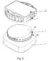
- FIG. 2is a partially-exploded perspective view of the pill bottle shown in FIG. 1 ;
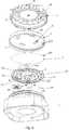
- FIG. 6is a top perspective view of a container formed in accordance with the present invention.
- FIG. 8is a cross-sectional view of the pill bottle shown in FIG. 1 , as taken along line 8 - 8 in FIG. 1 ;
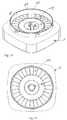
- FIG. 9is a top plan view of a container portion of a pill bottle formed in accordance with the present invention having a plurality of pills situated in pill wells within the container;
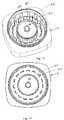
- FIG. 10is a top perspective view of a container formed in accordance with an alternative embodiment of the present invention.
- FIG. 11is a top plan view of the container shown in FIG. 10 ;
- FIG. 14is a top perspective view of a container formed in accordance with yet another alternative embodiment of the present invention.
- FIG. 15is a top plan view of the container shown in FIG. 14 ;
- FIGS. 16-19are each a top plan view of a pill bottle formed in accordance with one embodiment of the invention depicting a typical succession of steps for releasing a first and then a second pill from its respective pill well;
- FIG. 20is a cross-sectional view of a pill bottle formed in accordance with the present invention and illustrating a tablet-style pill arranged on its edge, ready for dispensing in accordance with the methods of the present invention.
- a senior-friendly, child-resistant pill bottle 1that combines the benefits of a conventional blister pack pill dispenser with a unit dose pill bottle, and includes a cap assembly 3 , a dial 9 , and a container 11 .
- Cap assembly 3includes a cap 4 having an enlarged outer diameter so as to be easily gripped and a child-resistant closure 5 ( FIGS. 4 and 5 ). These features are provided in pill bottle 1 to make the device more senior-friendly, while at the same time meeting the applicable child-resistance standards.
- a handle 12is provided on dial 9 that includes a dosage-access chimney or passageway 14 to allow the user to eject one pill at a time for ingestion.
- a peel-away foil seal 7sealingly engages the rim of container 11 , above dial 9 , so as to prevent contamination and guard compound stability during storage of pill bottle 1 .
- Peel-away foil seal 7must be removed before a user is able to access the rotatable dial 9 .
- each pill 13is preferably arranged and oriented “on-end” or “on-edge” within container 11 , so as to be arranged and oriented to rest within the pill bottle on either a tip end ( FIG. 9 ) or edge ( FIG. 20 ).
- Senior-friendly, child-resistant pill bottle 1ensures compound stability while providing easy and safe access to the stored medication by using the peel-away foil seal during initial shipping and storage and rotatable dial 9 after removal of the peel-away seal to allow for only one pill to be exposed to the environment at a time. This construction minimizes the possibility of contamination of yet undisturbed pills.
- Senior-friendly, child-resistant pill bottle 1also provides a benefit in the manufacturing of the prescription medication and its packaging.
- the arrangement of pill wells within the bottleis such that a conventional blister pack machine of the type currently in use by pharmaceutical packagers may be used with the present invention without need for modifications to the packaging machines or assembly process.
- the larger child-resistant capallows for a larger space for patient information, making it easier for the patient to read the information that is usually on the often rounded, vertically oriented face of a conventional pill bottle.
- enlarged cap 4 of cap assembly 3includes a brim 16 having an annular wall 18 projecting outwardly from a bottom surface 20 .
- Brim 16often includes a recess 22 that is sized and shaped to receive a label or other identifier of the type well known in the art.
- Bottom surface 20includes one or more integrally molded drive lugs 24 that are circularly disposed adjacent to the interior surface of annular wall 18 .
- Child-resistant closure 5comprises a circular base 27 and a peripheral annular wall 29 , and is complimentarily sized and shaped so as to be fitted within cap 4 .
- Circular base 27has an outer diameter that is less than the inner diameter of annular wall 18 of cap 4 .
- Annular wall 29projects downwardly from the peripheral edge of the bottom surface of circular base 27 .
- a plurality of ratchet lugs 30are integrally formed with, and circularly disposed about a top surface 32 of circular base 27 in complementary relation to drive lugs 24 on bottom surface 20 of cap 4 .
- the inner surface of annular wall 18often includes a thread or bayonet-type mount 23 .
- dial 9includes a shield 35 having a top surface 37 , a bottom surface 39 , and a central opening 40 .
- Handle 12comprises two diametrically opposed grips 41 a and 41 b that each project upwardly from top surface 37 , with central opening 40 disposed between them.
- Grip 41 adefines an opening 43 in a top surface 45 that communicates with a corresponding opening 46 in bottom surface 39 , through dosage access chimney 14 .
- a counter window 50is defined adjacent to a peripheral edge of dial 9 .
- An axle-tube 52projects downwardly from bottom surface 39 in coaxial annular relation to central opening 40 .
- a dial ratchet 54 and a dosage counter snap-tube 55each project downwardly from bottom surface 39 in substantially opposed spaced relation to one another about axle-tube 52 ( FIG. 5 ).
- Dosage-counter snap tube 55is central located within a dosage counter recess 58 formed in bottom surface 39 of dial 9 , which forms a corresponding prominence on top surface 37 of dial 9 .
- a dosage-counter disk 60is assembled to the under side of dial 9 .
- the top surface of dosage-counter disk 60has indicia 62 , e.g., numbers or letters, etc., that are representative of time period intervals such as days of the week or months of the year.
- a gear 64projects downwardly from the bottom surface of dosage-counter disk 60 , often in annular relation to the center of dosage-counter disk 60 .
- container 11includes a mouth 70 , an annular gear wall 72 , an annular divider 74 , an annular container wall 76 , and a base wall 77 .
- mouth 70is defined by an annular wall 80 that includes a rim 82 and an outer surface that often includes a thread or bayonet-type mount 83 that complements thread or bayonet-type mount 23 on the inner surface of annular wall 18 of enlarged cap 4 .
- a snap tube 85projects upwardly from a central portion of base wall 77 .
- Annular gear wall 72comprises an outer surface 88 and an inner surface 90 , and projects upwardly from base wall 77 in radially-spaced, coaxial relation to snap tube 85 .
- a plurality of circumferentially arranged dosage counter gear-teeth 96project inwardly from inner surface 90 of annular gear wall 72 and are positioned atop dial gear-teeth 94 .
- Each trough 102 defined by outer surface 98corresponds to a ridge 104 defined by inner surface 100
- each ridge 104 defined by outer surface 98corresponds to a trough 102 defined by inner surface 100
- Troughs 102 and ridges 104may define a smooth, sinusoidal curve or a more angular, saw tooth shape.
- a confronting pair of adjacent ribs 92 a , 92 bis located in spaced confronting relation to each of troughs 102 defined by inner surface 100 so as to define a plurality of pill wells 108 between annular gear wall 72 and annular divider 74 .
- annular divider 72may be formed as a series of annularly arranged, spaced barriers 105 or posts 106 instead of a continuous undulating wall ( FIGS. 10-15 ).
- a plurality of individual compartments 109may be formed in annular relation to snap tube 85 and annular gear wall 72 and into which pills 13 may be fed.
- pill wells 108 , 122combine to allow for the arrangement of a plurality of pills 13 so as to define a first circle of pills (located in pill wells 108 ) that is concentrically surrounded by a second circle of pills (located in pill wells 122 ) with the first circle of pills being angularly off-set with respect to the second circle of pills, i.e., clockwise or counter-clockwise, by an angular incremental amount, e.g., between about 3° and about 9°, with about 6° being preferred ( FIGS. 9 , and 16 - 19 ).
- This arrangement of pills 13 and dial closure 9 within senior-friendly, child-resistant pill bottle 1advantageously provides for a minimum exposure of yet to be dispensed pills during dispensing of a single pill.
- Senior-friendly, child-resistant pill bottle 1may be charged with medication by any number of conventional packaging machines and methods.
- senior-friendly, child-resistant pill bottle 1may be filled with pills 13 in a packaging machine of the type that has a portion suitable for separating a quantity of loose pills 13 into individualized compartments to thereby separately feed each pill 13 through a chute in an end-to-end orientation so as to be positioned such that each pill 13 may be individually positioned within a pill well 108 , 122 .
- Loose pills 13may also be separated into pairs or larger groupings for gang insertion into pill wells 108 , 122 .
- troughs 102 and ribs 92 , 120advantageously combine to allow for “on-end” storage of pills 13 within container 11 , i.e., pills that are arranged and oriented to rest within the pill bottle on a tip end so that each pill has its long axis aligned with a vertical orientation, that is often substantially parallel to annular divider 72 .
- This arrangement of pills 13advantageously provides for the minimum pill surface area to be exposed to outside environments during handling of container 11 .
- senior-friendly, child-resistant pill bottle 1may house and dispense a very wide variety of pills, tablets, and lozenges, i.e., any shaped cake of a fixed amount of a compressed powdered drug, usually intended to be swallowed whole or dissolved in the mouth, and of widely varying sizes, shapes, and compositions.
- dial 9may be assembled to container 11 .
- dial 9is oriented so that axle-tube 52 is aligned in confronting coaxial relation with snap tube 85 of container 11 . Once in this position, dial 9 is moved toward container 11 until snap tube 85 enters and securely engages an inner portion of axle-tube 52 . At the same time, dial ratchet 54 slips into operative engagement with one of the corresponding dial gear teeth 94 disposed upon inner surface 90 of annular gear wall 72 . As a result of this construction, when grips 41 a and 41 b are rotated clockwise, dial 9 freely rotates clockwise about snap tube 85 within container 11 , but is restrained from rotating counterclockwise by the operative engagement of dial ratchet 54 with one of the corresponding dial gear teeth 94 .
- peel-away foil seal 7is sealingly attached to rim 82 of container 11 thereby ensuring compound stability for the medications stored within container 11 .
- Peel-away foil seal 7often has a tab 95 extending from a peripheral portion to facilitate its removal from mouth 70 of container 11 .
- Cap assembly 3is then positioned above peel-away foil seal 7 and mouth 70 of container 11 so that circular base 27 of child-resistant closure 5 is aligned in confronting coaxial relation with mouth 70 of container 11 . In this position, plurality of ratchet lugs 30 are positioned in confronting adjacent relation to bottom surface 20 and drive lugs 24 of cap 4 .
- Cap assembly 3is then moved toward mouth 70 of container 11 until thread or bayonet-type mount 23 of child-resistant closure 5 engage corresponding complementary thread or bayonet-type mount 83 located on annular wall 80 of container 11 .
- dial 9has dosage-counter disk 60 positioned on dosage-counter snap tube 55 so that it may be selectively and incrementally rotated.
- gear 64 on the underside of dosage-counter disk 60slips into operative engagement with one of the corresponding dosage-counter gear teeth 96 disposed above dial gear-teeth 94 on annular gear wall 72 .
- dosage-counter disk 60may be advanced, i.e., rotated, a predetermined amount depending upon the interval between dosages of the medication delivered by pill 13 .
- the patientmerely rotates dial 9 with respect to container 11 in a clockwise motion an angular incremental amount, e.g., between about 2° and about 10° depending upon the size of the pills being stored, so as to position chimney 14 above a successive next pill 13 in. e.g., a next successive pill well 108 or 122 .
- the patientsimply checks counter window 50 to determine whether they have taken their medication on any given day. It should be understood that when pill wells 108 , 122 are fully charged with pills 13 , many days' dosage of medication may be supplied in a single pill bottle 1 , e.g., 28 days, 31 days, 40 days, 60 days, etc.
Landscapes
- Engineering & Computer Science (AREA)
- Mechanical Engineering (AREA)
- Closures For Containers (AREA)
- Containers Having Bodies Formed In One Piece (AREA)
Abstract
Description
Claims (15)
Priority Applications (3)
| Application Number | Priority Date | Filing Date | Title |
|---|---|---|---|
| US11/693,452US7735684B2 (en) | 2007-01-19 | 2007-03-29 | Pill bottle |
| PCT/US2008/051268WO2008089306A2 (en) | 2007-01-19 | 2008-01-17 | Pill bottle |
| US12/123,003US20080251531A1 (en) | 2007-01-19 | 2008-05-19 | Large capacity pill bottle with improved child resistance |
Applications Claiming Priority (2)
| Application Number | Priority Date | Filing Date | Title |
|---|---|---|---|
| US88573207P | 2007-01-19 | 2007-01-19 | |
| US11/693,452US7735684B2 (en) | 2007-01-19 | 2007-03-29 | Pill bottle |
Related Child Applications (1)
| Application Number | Title | Priority Date | Filing Date |
|---|---|---|---|
| US12/123,003Continuation-In-PartUS20080251531A1 (en) | 2007-01-19 | 2008-05-19 | Large capacity pill bottle with improved child resistance |
Publications (2)
| Publication Number | Publication Date |
|---|---|
| US20080173666A1 US20080173666A1 (en) | 2008-07-24 |
| US7735684B2true US7735684B2 (en) | 2010-06-15 |
Family
ID=39636697
Family Applications (1)
| Application Number | Title | Priority Date | Filing Date |
|---|---|---|---|
| US11/693,452Expired - Fee RelatedUS7735684B2 (en) | 2007-01-19 | 2007-03-29 | Pill bottle |
Country Status (2)
| Country | Link |
|---|---|
| US (1) | US7735684B2 (en) |
| WO (1) | WO2008089306A2 (en) |
Cited By (22)
| Publication number | Priority date | Publication date | Assignee | Title |
|---|---|---|---|---|
| US9345645B1 (en)* | 2015-04-07 | 2016-05-24 | Alex H. Chernyak | Bi-directional adaptive drug dispenser for managing divergence between pre-set regimen and actual performance |
| US9434528B2 (en) | 2013-12-16 | 2016-09-06 | Rosemary Ashbaugh | Pill dispenser |
| USD779955S1 (en) | 2015-09-10 | 2017-02-28 | Cvs Pharmacy, Inc. | Bottle |
| USD780589S1 (en) | 2015-09-10 | 2017-03-07 | Cvs Pharmacy, Inc. | Bottle |
| USD780588S1 (en) | 2015-09-10 | 2017-03-07 | Cvs Cvs Pharmacy, Inc. | Bottle |
| USD786086S1 (en) | 2015-08-31 | 2017-05-09 | Cvs Pharmacy, Inc. | Bottle with cap |
| USD786683S1 (en) | 2015-08-31 | 2017-05-16 | Cvs Pharmacy, Inc. | Bottle with cap |
| USD786674S1 (en) | 2015-08-31 | 2017-05-16 | Cvs Pharmacy, Inc. | Bottle cap |
| US9656796B1 (en)* | 2014-03-17 | 2017-05-23 | Michael Carl Cammarata | Pill dispensing bottle system |
| USD792233S1 (en) | 2015-08-31 | 2017-07-18 | Cvs Pharmacy, Inc. | Bottle with cap |
| US20170267440A1 (en)* | 2014-07-18 | 2017-09-21 | Donald T. Sanders | Combination Medicine Containers and Dispensers |
| US9908686B2 (en) | 2014-07-01 | 2018-03-06 | Ameizen Llc | Pill dispenser and system |
| US10073954B2 (en) | 2016-08-26 | 2018-09-11 | Changhai Chen | Dispenser system and methods for medication compliance |
| US10482703B2 (en)* | 2014-06-30 | 2019-11-19 | 3M Innovative Properties Company | Earplug dispenser with asymmetric mixing body |
| US10507957B2 (en) | 2014-09-18 | 2019-12-17 | Colgate-Palmolive Company | Flip-top cap |
| US10722431B2 (en) | 2016-08-26 | 2020-07-28 | Changhai Chen | Dispenser system and methods for medication compliance |
| US10872482B1 (en) | 2017-11-22 | 2020-12-22 | Alexander Montgomery Colton | Personalized lid for prescription bottles |
| USD917153S1 (en)* | 2019-11-18 | 2021-04-27 | Pillo, Inc. | Pill container |
| USD921354S1 (en)* | 2019-10-22 | 2021-06-08 | Phillips-Medisize A/S | Pill dispenser |
| US11246805B2 (en) | 2016-08-26 | 2022-02-15 | Changhai Chen | Dispenser system and methods for medication compliance |
| WO2023178351A1 (en)* | 2022-03-18 | 2023-09-21 | Dose Health, LLC | Systems and methods for dispensing medications using authentication mechanisms |
| US11912478B2 (en) | 2020-03-02 | 2024-02-27 | Twistwise LLC | Dosage reminder indicator for container lids |
Families Citing this family (27)
| Publication number | Priority date | Publication date | Assignee | Title |
|---|---|---|---|---|
| US20080251531A1 (en)* | 2007-01-19 | 2008-10-16 | One World Design & Manufacturing Group | Large capacity pill bottle with improved child resistance |
| US20090071864A1 (en)* | 2007-09-18 | 2009-03-19 | One World Design & Manufacturing Group Ltd. | Mechanism for Permanently Attaching a Blister Card within a Container |
| US20090084801A1 (en)* | 2007-09-27 | 2009-04-02 | One World Design & Manufacturing Group Ltd. | Child-resistant compliance pill bottle |
| US20090095649A1 (en)* | 2007-10-10 | 2009-04-16 | One World Design & Manufacturing Group Ltd. | Child-Resistant Container for Housing a Blister Card |
| US20090127157A1 (en)* | 2007-11-15 | 2009-05-21 | One World Design & Manufacturing Group, Ltd. | Pill bottle |
| US20090127156A1 (en)* | 2007-11-15 | 2009-05-21 | Yaotsung Tung | Child-Resistant Container for Housing a Blister Card |
| US20090184022A1 (en)* | 2008-01-18 | 2009-07-23 | One World Design And Manufacturing Group, Ltd. | Child resistant container for housing a blister card |
| US9046403B2 (en)* | 2010-02-01 | 2015-06-02 | Mallinckrodt Llc | Systems and methods for managing use of a medicament |
| US20120234852A1 (en)* | 2011-03-17 | 2012-09-20 | Peter George Guthrie | Automated storage and dispensing system |
| US10201479B2 (en) | 2014-11-05 | 2019-02-12 | Arthur Nazginov | Adjustable indicators for container assemblies |
| US10198975B2 (en) | 2014-11-05 | 2019-02-05 | Arthur Nazginov | Adjustable indicators for container assemblies |
| US10010486B2 (en)* | 2014-11-05 | 2018-07-03 | Arthur Nazginov | Adjustable indicators for container assemblies |
| CN104485056A (en)* | 2015-01-13 | 2015-04-01 | 谭翼翔 | Thin part delivery machine |
| US10247327B2 (en)* | 2016-01-08 | 2019-04-02 | Watts Regulator Co. | Boiler fill valve with fast-fill and non-oscilatting dial features |
| US11054129B2 (en) | 2016-01-08 | 2021-07-06 | Watts Water Technologies | Boiler fill valve with regulated fast-fill |
| WO2018126190A1 (en)* | 2016-12-30 | 2018-07-05 | Brady Robert Owen | Tablet and capsule dispensing assembly |
| WO2018183141A1 (en)* | 2017-03-30 | 2018-10-04 | Merck Sharp & Dohme Corp. | Dispensing device for micro-tablets |
| US11383922B2 (en) | 2018-02-05 | 2022-07-12 | Ecolab Usa Inc. | Packaging and docking system for non-contact chemical dispensing |
| PL3752281T3 (en) | 2018-02-13 | 2022-08-22 | Ecolab USA, Inc. | LAYOUT AND METHOD FOR DISSOLVING CHEMICAL SOLIDS AND GENERATING LIQUID SOLUTIONS |
| US20190328619A1 (en)* | 2018-04-27 | 2019-10-31 | Pilleve, Inc. | Pill dispensing system |
| SG11202108520XA (en) | 2019-02-05 | 2021-09-29 | Ecolab Usa Inc | Packaging and docking system for non-contact chemical dispensing |
| US11440709B2 (en)* | 2020-04-20 | 2022-09-13 | Dongguan Lk Tin Packaging Co., Ltd. | Container with security lock |
| CN112193562B (en)* | 2020-10-30 | 2024-12-13 | 陕西省第二人民医院 | Manual medicine dispensing bottle |
| CN112320098B (en)* | 2020-11-07 | 2024-06-11 | 安徽洁诺德塑胶包装有限公司 | Stop motion tooth subassembly, ration feeding mechanism and ration feeding jar |
| CN112660785A (en)* | 2020-12-30 | 2021-04-16 | 艾福玛医疗科技(常州)有限公司 | Flywheel and point medicine machine suitable for point medicine machine divides medicine |
| CN112918873B (en)* | 2021-04-12 | 2024-08-23 | 江苏慧安智远智能医疗科技有限公司 | Automatic medicine box |
| US11819473B1 (en)* | 2021-12-03 | 2023-11-21 | Felix Mawuli Anyomi | Access counting lid for a prescription pill bottle |
Citations (49)
| Publication number | Priority date | Publication date | Assignee | Title |
|---|---|---|---|---|
| US630452A (en)* | 1899-05-22 | 1899-08-08 | Harry L Dooley | Corn-planter. |
| US932983A (en)* | 1909-05-06 | 1909-08-31 | James R Grubb | Waste-proof-traveler magazine. |
| US2610100A (en)* | 1947-12-26 | 1952-09-09 | Vendorlator Mfg Company | Coin controlled vending machine |
| US2828005A (en)* | 1954-11-02 | 1958-03-25 | Maurine E Ricke | Dispenser |
| US3162287A (en)* | 1963-05-29 | 1964-12-22 | Lupovici David | Vending machine |
| US3227127A (en)* | 1964-07-15 | 1966-01-04 | Gayle Robert | Pill dispenser with indicating means |
| US3339798A (en)* | 1965-11-18 | 1967-09-05 | Katz Jacob | Article dispenser having a plurality of rotatably mounted sources with actuating means |
| US3394796A (en)* | 1967-07-25 | 1968-07-30 | Warren R. Jensen | Pill dispenser |
| US3495567A (en)* | 1968-02-20 | 1970-02-17 | Creative Packaging Inc | Pill dispenser with indicating dial |
| US3722739A (en) | 1970-03-23 | 1973-03-27 | M Blumberg | Pill dispenser having clockwork for periodic dispensing |
| US3895737A (en)* | 1974-03-07 | 1975-07-22 | Int Tools 1973 Ltd | Child-proof dispensing container and cover assembly |
| US3921806A (en) | 1974-06-10 | 1975-11-25 | Joyce L Wawracz | Pill dispenser |
| US3926335A (en) | 1974-03-18 | 1975-12-16 | Thomas C Dangles | Capsule or pill dispenser-sure way dial a pill |
| US4124143A (en)* | 1977-02-11 | 1978-11-07 | Ryder International Corporation | Pill dispenser |
| US4319690A (en)* | 1979-12-13 | 1982-03-16 | International Tools (1973) Limited | Child-resistant closure and container assembly including improved outer cap |
| US4454971A (en)* | 1982-08-09 | 1984-06-19 | Poehlmann Paul W | Projectile magazine |
| US4460106A (en)* | 1981-11-02 | 1984-07-17 | Moulding Jr Thomas S | Pill dispenser |
| US4572376A (en) | 1982-09-16 | 1986-02-25 | Wrennall Richard K | Dial pill box |
| US4572403A (en)* | 1984-02-01 | 1986-02-25 | Rafael Benaroya | Timed dispensing device for tablets, capsules, and the like |
| US4611727A (en)* | 1985-02-20 | 1986-09-16 | Graff James C | Solid oral dosage dispenser with safety, tamper-proof and sanitation features |
| US4838453A (en)* | 1988-02-16 | 1989-06-13 | Luckstead Jon D | Pill dispenser |
| US4939705A (en)* | 1988-11-23 | 1990-07-03 | Aprex Corporation | Drug dispensing event detector |
| US5005281A (en)* | 1990-08-20 | 1991-04-09 | Dynamics Systems International Inc. | Method of making rotor and stator pole assemblies by stamping magnetic plate |
| US5392952A (en)* | 1994-01-10 | 1995-02-28 | Bowden; James R. | Pill dispensisng device providing overdosage protection |
| US5575392A (en)* | 1989-05-26 | 1996-11-19 | Cutler; Paul A. | Pill dispenser |
| US5603429A (en)* | 1995-10-31 | 1997-02-18 | Cap Toys, Inc. | Motorized hand-held transportable dispenser for dispensing disc-shaped objects one at a time |
| US5664697A (en) | 1995-10-31 | 1997-09-09 | Ortho Pharmaceutical Corporation | Automatically advancing pill regimen device |
| US5678712A (en)* | 1995-05-26 | 1997-10-21 | Owens-Illnois Closure Inc. | Child resistant reminder closure |
| US6021918A (en)* | 1998-12-11 | 2000-02-08 | Medical Equipment Development Services | Programmable dispenser for medication |
| US6039208A (en)* | 1994-07-29 | 2000-03-21 | Ortho Pharmaceutical Corporation | Variable day start tablet dispenser |
| US6098835A (en) | 1998-09-03 | 2000-08-08 | Valley Design Inc. | Child resistant pill rotating disk dispenser |
| US6109252A (en)* | 1997-04-05 | 2000-08-29 | Stevens; Simon Benjamin | Projectile feed system |
| US6193103B1 (en) | 1996-06-14 | 2001-02-27 | Akzo Nobel N.V. | Pill dispenser |
| US6206216B1 (en)* | 1999-07-26 | 2001-03-27 | Top Seal Corporation | Child-resistant cap |
| US6234343B1 (en) | 1999-03-26 | 2001-05-22 | Papp Enterprises, Llc | Automated portable medication radial dispensing apparatus and method |
| USD451666S1 (en) | 2001-02-02 | 2001-12-11 | Carol M Zastrow | Pill organizer and dispenser |
| US6364155B1 (en)* | 2000-04-07 | 2002-04-02 | Owens-Illinois Closure Inc. | Child resistant pill dispensing package |
| US6415202B1 (en)* | 1998-06-19 | 2002-07-02 | Van Halfacre | Tamper resistant programmable medicine dispenser |
| USD460897S1 (en) | 2001-12-20 | 2002-07-30 | Admiralty Island Fisheries, Inc. | Shrimp ring tray |
| US6427865B1 (en)* | 1998-04-15 | 2002-08-06 | Kenneth Stillwell | Automatic pill dispenser |
| US6510668B2 (en)* | 2001-01-26 | 2003-01-28 | Jv Medi Co., Ltd. | Drum of medicine sharing and packing device |
| USD473786S1 (en) | 2002-03-26 | 2003-04-29 | Kenki (H.K.) Ltd. | Press-pill dispenser |
| US6805258B2 (en) | 2002-05-09 | 2004-10-19 | Dordan Manufacturing Co. | Capsule dispenser |
| USD502801S1 (en) | 2004-01-06 | 2005-03-15 | Elliot Baum | Combined pill dispenser and pill holder |
| US6874652B2 (en) | 2000-09-07 | 2005-04-05 | Bang & Olufsen Medicom A/S | Methods for dispensing of tablets from an apparatus, apparatuses for performing the methods and use of such apparatuses |
| US7100793B2 (en) | 2003-01-06 | 2006-09-05 | Elliot Baum | Pill dispenser |
| US7100797B2 (en) | 2003-07-09 | 2006-09-05 | Talisman Technologies, Llc | One dose at-a-time pill dispenser and container having same |
| US7104417B2 (en) | 2002-05-20 | 2006-09-12 | Comar, Inc. | Pill dispensing apparatus and system |
| US20060225383A1 (en)* | 2005-04-08 | 2006-10-12 | Jm Smith Corporation | Pharmaceutical singulation counting and dispensing system |
- 2007
- 2007-03-29USUS11/693,452patent/US7735684B2/ennot_activeExpired - Fee Related
- 2008
- 2008-01-17WOPCT/US2008/051268patent/WO2008089306A2/enactiveApplication Filing
Patent Citations (51)
| Publication number | Priority date | Publication date | Assignee | Title |
|---|---|---|---|---|
| US630452A (en)* | 1899-05-22 | 1899-08-08 | Harry L Dooley | Corn-planter. |
| US932983A (en)* | 1909-05-06 | 1909-08-31 | James R Grubb | Waste-proof-traveler magazine. |
| US2610100A (en)* | 1947-12-26 | 1952-09-09 | Vendorlator Mfg Company | Coin controlled vending machine |
| US2828005A (en)* | 1954-11-02 | 1958-03-25 | Maurine E Ricke | Dispenser |
| US3162287A (en)* | 1963-05-29 | 1964-12-22 | Lupovici David | Vending machine |
| US3227127A (en)* | 1964-07-15 | 1966-01-04 | Gayle Robert | Pill dispenser with indicating means |
| US3339798A (en)* | 1965-11-18 | 1967-09-05 | Katz Jacob | Article dispenser having a plurality of rotatably mounted sources with actuating means |
| US3394796A (en)* | 1967-07-25 | 1968-07-30 | Warren R. Jensen | Pill dispenser |
| US3495567A (en)* | 1968-02-20 | 1970-02-17 | Creative Packaging Inc | Pill dispenser with indicating dial |
| US3722739A (en) | 1970-03-23 | 1973-03-27 | M Blumberg | Pill dispenser having clockwork for periodic dispensing |
| US3895737A (en)* | 1974-03-07 | 1975-07-22 | Int Tools 1973 Ltd | Child-proof dispensing container and cover assembly |
| US3926335A (en) | 1974-03-18 | 1975-12-16 | Thomas C Dangles | Capsule or pill dispenser-sure way dial a pill |
| US3921806A (en) | 1974-06-10 | 1975-11-25 | Joyce L Wawracz | Pill dispenser |
| US4124143A (en)* | 1977-02-11 | 1978-11-07 | Ryder International Corporation | Pill dispenser |
| US4319690A (en)* | 1979-12-13 | 1982-03-16 | International Tools (1973) Limited | Child-resistant closure and container assembly including improved outer cap |
| US4460106A (en)* | 1981-11-02 | 1984-07-17 | Moulding Jr Thomas S | Pill dispenser |
| US4454971A (en)* | 1982-08-09 | 1984-06-19 | Poehlmann Paul W | Projectile magazine |
| US4572376A (en) | 1982-09-16 | 1986-02-25 | Wrennall Richard K | Dial pill box |
| US4572403A (en)* | 1984-02-01 | 1986-02-25 | Rafael Benaroya | Timed dispensing device for tablets, capsules, and the like |
| US4611727A (en)* | 1985-02-20 | 1986-09-16 | Graff James C | Solid oral dosage dispenser with safety, tamper-proof and sanitation features |
| US4838453A (en)* | 1988-02-16 | 1989-06-13 | Luckstead Jon D | Pill dispenser |
| US4939705A (en)* | 1988-11-23 | 1990-07-03 | Aprex Corporation | Drug dispensing event detector |
| US5575392A (en)* | 1989-05-26 | 1996-11-19 | Cutler; Paul A. | Pill dispenser |
| US5005281A (en)* | 1990-08-20 | 1991-04-09 | Dynamics Systems International Inc. | Method of making rotor and stator pole assemblies by stamping magnetic plate |
| US5392952A (en)* | 1994-01-10 | 1995-02-28 | Bowden; James R. | Pill dispensisng device providing overdosage protection |
| US6039208A (en)* | 1994-07-29 | 2000-03-21 | Ortho Pharmaceutical Corporation | Variable day start tablet dispenser |
| US5678712A (en)* | 1995-05-26 | 1997-10-21 | Owens-Illnois Closure Inc. | Child resistant reminder closure |
| US5664697A (en) | 1995-10-31 | 1997-09-09 | Ortho Pharmaceutical Corporation | Automatically advancing pill regimen device |
| US5664697B1 (en) | 1995-10-31 | 1998-09-15 | Ortho Pharma Corp | Automatically advancing pill regimen device |
| US5603429A (en)* | 1995-10-31 | 1997-02-18 | Cap Toys, Inc. | Motorized hand-held transportable dispenser for dispensing disc-shaped objects one at a time |
| US6193103B1 (en) | 1996-06-14 | 2001-02-27 | Akzo Nobel N.V. | Pill dispenser |
| US6109252A (en)* | 1997-04-05 | 2000-08-29 | Stevens; Simon Benjamin | Projectile feed system |
| US6427865B1 (en)* | 1998-04-15 | 2002-08-06 | Kenneth Stillwell | Automatic pill dispenser |
| US6415202B1 (en)* | 1998-06-19 | 2002-07-02 | Van Halfacre | Tamper resistant programmable medicine dispenser |
| US6098835A (en) | 1998-09-03 | 2000-08-08 | Valley Design Inc. | Child resistant pill rotating disk dispenser |
| US6021918A (en)* | 1998-12-11 | 2000-02-08 | Medical Equipment Development Services | Programmable dispenser for medication |
| US6234343B1 (en) | 1999-03-26 | 2001-05-22 | Papp Enterprises, Llc | Automated portable medication radial dispensing apparatus and method |
| US6206216B1 (en)* | 1999-07-26 | 2001-03-27 | Top Seal Corporation | Child-resistant cap |
| US6364155B1 (en)* | 2000-04-07 | 2002-04-02 | Owens-Illinois Closure Inc. | Child resistant pill dispensing package |
| US6502717B1 (en) | 2000-04-07 | 2003-01-07 | Owens-Illinois Closure Inc. | Child resistant pill dispensing package |
| US6874652B2 (en) | 2000-09-07 | 2005-04-05 | Bang & Olufsen Medicom A/S | Methods for dispensing of tablets from an apparatus, apparatuses for performing the methods and use of such apparatuses |
| US6510668B2 (en)* | 2001-01-26 | 2003-01-28 | Jv Medi Co., Ltd. | Drum of medicine sharing and packing device |
| USD451666S1 (en) | 2001-02-02 | 2001-12-11 | Carol M Zastrow | Pill organizer and dispenser |
| USD460897S1 (en) | 2001-12-20 | 2002-07-30 | Admiralty Island Fisheries, Inc. | Shrimp ring tray |
| USD473786S1 (en) | 2002-03-26 | 2003-04-29 | Kenki (H.K.) Ltd. | Press-pill dispenser |
| US6805258B2 (en) | 2002-05-09 | 2004-10-19 | Dordan Manufacturing Co. | Capsule dispenser |
| US7104417B2 (en) | 2002-05-20 | 2006-09-12 | Comar, Inc. | Pill dispensing apparatus and system |
| US7100793B2 (en) | 2003-01-06 | 2006-09-05 | Elliot Baum | Pill dispenser |
| US7100797B2 (en) | 2003-07-09 | 2006-09-05 | Talisman Technologies, Llc | One dose at-a-time pill dispenser and container having same |
| USD502801S1 (en) | 2004-01-06 | 2005-03-15 | Elliot Baum | Combined pill dispenser and pill holder |
| US20060225383A1 (en)* | 2005-04-08 | 2006-10-12 | Jm Smith Corporation | Pharmaceutical singulation counting and dispensing system |
Cited By (24)
| Publication number | Priority date | Publication date | Assignee | Title |
|---|---|---|---|---|
| US9434528B2 (en) | 2013-12-16 | 2016-09-06 | Rosemary Ashbaugh | Pill dispenser |
| US9656796B1 (en)* | 2014-03-17 | 2017-05-23 | Michael Carl Cammarata | Pill dispensing bottle system |
| US10482703B2 (en)* | 2014-06-30 | 2019-11-19 | 3M Innovative Properties Company | Earplug dispenser with asymmetric mixing body |
| US9908686B2 (en) | 2014-07-01 | 2018-03-06 | Ameizen Llc | Pill dispenser and system |
| US10479588B2 (en)* | 2014-07-18 | 2019-11-19 | Donald T. Sanders | Combination medicine containers and dispensers |
| US20170267440A1 (en)* | 2014-07-18 | 2017-09-21 | Donald T. Sanders | Combination Medicine Containers and Dispensers |
| US10507957B2 (en) | 2014-09-18 | 2019-12-17 | Colgate-Palmolive Company | Flip-top cap |
| US9345645B1 (en)* | 2015-04-07 | 2016-05-24 | Alex H. Chernyak | Bi-directional adaptive drug dispenser for managing divergence between pre-set regimen and actual performance |
| USD786674S1 (en) | 2015-08-31 | 2017-05-16 | Cvs Pharmacy, Inc. | Bottle cap |
| USD792233S1 (en) | 2015-08-31 | 2017-07-18 | Cvs Pharmacy, Inc. | Bottle with cap |
| USD786683S1 (en) | 2015-08-31 | 2017-05-16 | Cvs Pharmacy, Inc. | Bottle with cap |
| USD786086S1 (en) | 2015-08-31 | 2017-05-09 | Cvs Pharmacy, Inc. | Bottle with cap |
| USD780588S1 (en) | 2015-09-10 | 2017-03-07 | Cvs Cvs Pharmacy, Inc. | Bottle |
| USD837058S1 (en) | 2015-09-10 | 2019-01-01 | Cvs Pharmacy, Inc. | Bottle |
| USD780589S1 (en) | 2015-09-10 | 2017-03-07 | Cvs Pharmacy, Inc. | Bottle |
| USD779955S1 (en) | 2015-09-10 | 2017-02-28 | Cvs Pharmacy, Inc. | Bottle |
| US10073954B2 (en) | 2016-08-26 | 2018-09-11 | Changhai Chen | Dispenser system and methods for medication compliance |
| US10722431B2 (en) | 2016-08-26 | 2020-07-28 | Changhai Chen | Dispenser system and methods for medication compliance |
| US11246805B2 (en) | 2016-08-26 | 2022-02-15 | Changhai Chen | Dispenser system and methods for medication compliance |
| US10872482B1 (en) | 2017-11-22 | 2020-12-22 | Alexander Montgomery Colton | Personalized lid for prescription bottles |
| USD921354S1 (en)* | 2019-10-22 | 2021-06-08 | Phillips-Medisize A/S | Pill dispenser |
| USD917153S1 (en)* | 2019-11-18 | 2021-04-27 | Pillo, Inc. | Pill container |
| US11912478B2 (en) | 2020-03-02 | 2024-02-27 | Twistwise LLC | Dosage reminder indicator for container lids |
| WO2023178351A1 (en)* | 2022-03-18 | 2023-09-21 | Dose Health, LLC | Systems and methods for dispensing medications using authentication mechanisms |
Also Published As
| Publication number | Publication date |
|---|---|
| US20080173666A1 (en) | 2008-07-24 |
| WO2008089306A2 (en) | 2008-07-24 |
| WO2008089306A3 (en) | 2008-09-25 |
Similar Documents
| Publication | Publication Date | Title |
|---|---|---|
| US7735684B2 (en) | Pill bottle | |
| US20080251531A1 (en) | Large capacity pill bottle with improved child resistance | |
| US7621231B2 (en) | Dosage reminder cap | |
| US4984709A (en) | Non-reversing tablet dispenser with counter | |
| US5850919A (en) | Compliance closure | |
| US20090127157A1 (en) | Pill bottle | |
| US7100797B2 (en) | One dose at-a-time pill dispenser and container having same | |
| US6138866A (en) | Variable day start tablet dispenser | |
| AU728571B2 (en) | Variable day start tablet dispenser | |
| US20060124658A1 (en) | Pill dispenser with patient compliant indicating means | |
| US5348158A (en) | Dispenser pack for the successive dispensing of a drug | |
| EP1056659B1 (en) | Dosing dispenser | |
| US9815611B2 (en) | Device and method for singularized dispensing of solid portions | |
| US20090050514A1 (en) | Dual compartment medicine container | |
| US9241871B2 (en) | Container | |
| US20190185249A1 (en) | Rotable cap system for dispensing one or two tablets or capsules from a pharmacy vial | |
| US20110147252A1 (en) | Packages and inserts useful for dispensing medicines | |
| US20080000799A1 (en) | Container 389 | |
| US3245589A (en) | Medication dispenser | |
| US20110155757A1 (en) | Packages and inserts thereof with guide wall for dispensing medicinal units | |
| US7604124B1 (en) | Dispensing container and package for pelletized products | |
| KR200328700Y1 (en) | Dispenser for foods or medicines | |
| NZ328492A (en) | Circular table package for loading into a dispenser system for delivery of tablet |
Legal Events
| Date | Code | Title | Description |
|---|---|---|---|
| AS | Assignment | Owner name:ONE WORLD DESIGN & MANUFACTURING GROUP, NEW JERSEY Free format text:ASSIGNMENT OF ASSIGNORS INTEREST;ASSIGNORS:COE, MATTHEW;COSTA, RICHARD;MACH, HUNG;REEL/FRAME:020377/0250 Effective date:20070328 Owner name:ONE WORLD DESIGN & MANUFACTURING GROUP,NEW JERSEY Free format text:ASSIGNMENT OF ASSIGNORS INTEREST;ASSIGNORS:COE, MATTHEW;COSTA, RICHARD;MACH, HUNG;REEL/FRAME:020377/0250 Effective date:20070328 | |
| STCF | Information on status: patent grant | Free format text:PATENTED CASE | |
| CC | Certificate of correction | ||
| FPAY | Fee payment | Year of fee payment:4 | |
| FEPP | Fee payment procedure | Free format text:MAINTENANCE FEE REMINDER MAILED (ORIGINAL EVENT CODE: REM.) | |
| FEPP | Fee payment procedure | Free format text:7.5 YR SURCHARGE - LATE PMT W/IN 6 MO, SMALL ENTITY (ORIGINAL EVENT CODE: M2555) | |
| MAFP | Maintenance fee payment | Free format text:PAYMENT OF MAINTENANCE FEE, 8TH YR, SMALL ENTITY (ORIGINAL EVENT CODE: M2552) Year of fee payment:8 | |
| FEPP | Fee payment procedure | Free format text:MAINTENANCE FEE REMINDER MAILED (ORIGINAL EVENT CODE: REM.); ENTITY STATUS OF PATENT OWNER: SMALL ENTITY | |
| LAPS | Lapse for failure to pay maintenance fees | Free format text:PATENT EXPIRED FOR FAILURE TO PAY MAINTENANCE FEES (ORIGINAL EVENT CODE: EXP.); ENTITY STATUS OF PATENT OWNER: SMALL ENTITY | |
| STCH | Information on status: patent discontinuation | Free format text:PATENT EXPIRED DUE TO NONPAYMENT OF MAINTENANCE FEES UNDER 37 CFR 1.362 | |
| FP | Lapsed due to failure to pay maintenance fee | Effective date:20220615 |