US7735669B2 - Modular case assembly device - Google Patents
Modular case assembly deviceDownload PDFInfo
- Publication number
- US7735669B2 US7735669B2US11/358,125US35812506AUS7735669B2US 7735669 B2US7735669 B2US 7735669B2US 35812506 AUS35812506 AUS 35812506AUS 7735669 B2US7735669 B2US 7735669B2
- Authority
- US
- United States
- Prior art keywords
- assembly device
- case
- case assembly
- lower case
- modular
- Prior art date
- Legal status (The legal status is an assumption and is not a legal conclusion. Google has not performed a legal analysis and makes no representation as to the accuracy of the status listed.)
- Active, expires
Links
Images


Classifications
- G—PHYSICS
- G06—COMPUTING OR CALCULATING; COUNTING
- G06F—ELECTRIC DIGITAL DATA PROCESSING
- G06F1/00—Details not covered by groups G06F3/00 - G06F13/00 and G06F21/00
- G06F1/16—Constructional details or arrangements
- G06F1/18—Packaging or power distribution
- G06F1/181—Enclosures
Definitions
- the present inventionrelates to a modular case assembly device, and more particularly to a modular case designed for use in a computer to effectively provide convenient and fast assembly and disassembly of an upper case and lower case, and which increases stability when assembled.
- Taiwan utility model No. 090217902entitled “Connecting Device for a Cover of a Computer Host Case”, which although practical, however, because the number of fastener interfaces is limited, thus, stability of the fasteners is still inadequate when used on relatively large cases.
- the primary objective of the present inventionis to provide a modular case assembly device that increases stability of an assembled upper case and lower case, and effectively achieve convenient and fast assembly and disassembly of the modular case.
- FIG. 1shows an exploded elevational view of a lower case and an upper case according to the present invention.
- FIG. 2shows an exploded elevational view of the upper case according to the present invention.
- FIG. 3shows an exploded elevational view of the lower case according to the present invention.
- FIG. 4shows an assembled elevational view according to the present invention.
- FIG. 5shows a side view depicting assembly of the upper case and the lower case according to the present invention.
- FIG. 6shows a side view depicting assemblage of the upper case and the lower case according to the present invention.
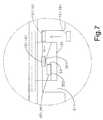
- FIG. 7shows an enlarged schematic view of area A of FIG. 6 .
- FIG. 8shows a cross-sectional view depicting a spring being resiliently deformed when pressed according to the present invention.
- FIGS. 1 , 2 , 3 and 4which show the modular case assembly device of the present invention comprising:
- a lower case 10(see FIG. 1 ), wherein a front wall 13 and a rear wall 14 protrude from a front end and a rear end of a bottom plate 12 respectively, a left wall 15 and a right wall 16 protrude from left and right sides of the bottom plate 12 respectively;
- an upper case 20structured from an upper plate 22 and left and right side wall plates 21 , ( 21 ), wherein rectangular depressions 23 , ( 23 ) are respectively defined on a top surface of the upper plate 22 , a through hole 24 is punched out of each of the rectangular depressions 23 , ( 23 ), and a longitudinally extended crosspiece 25 is formed on an edge of each of the through holes 24 ;
- resilient springs 30on a surface of each of which is formed a press portion 32 , a through hole 33 and a connecting portion 34 are further respectively formed on sides of the press portion 32 , a hook 35 extends from a side of the through hole 33 , and an arc-shaped protrusion 351 and a horizontal position fixing portion 352 are formed on an upper end of the hook 35 ; the connecting portion 34 affixes to a bottom surface of each of the depressions 23 , ( 23 ).
- Indentations 211are defined in the left and right side wall plates 21 , ( 21 ) and are positioned at an underside of each of the through holes 24 , and a clearance 28 is formed between the arc-shaped protrusion 351 and a top edge 212 of the indentation 211 (see FIG. 5 ).
- the protruding pieces 151 , 161 of the lower case 10transversally cross the clearances 28 and rest atop the position fixing portions 352 .
- At least more than one groove 27is positionally defined in the left and right side wall plates 21 , ( 21 ) of the upper case 20 , and a transverse position fixing groove 271 is formed in an interior of each of the grooves 27 , and an indentation 27 is formed on an exterior of each of the grooves 27 .
- Two or more joining holes 152 , 162are defined in the left and right walls 15 , 16 of the lower case 10 respectively, which are used to hold fast shafts 153 , 163 that embed into the grooves 27 .
- a lower protruding piece 201extends from an underside of a front end of the upper case 20 , and a groove 202 is formed between the lower protruding piece 201 and the upper plate 202 .
- a horizontally inwardly extending protruding plate 101is formed at a front end of the lower case 10 , which enables the lower protruding piece 201 to extend underneath the protruding plate 101 , thereby clasping the protruding piece 101 within the groove 202 .
- an outer cover 29covers and is affixed within each of the depressions 23 .
- Each of the outer covers 29is provided with a right through hole 291 that opens onto the through hole 24 of the depression 23 , ( 23 ).
- the through hole 33 defined in each of the springs 30provides for the crosspiece 25 to penetrate therethrough.
- the front and rear walls 13 , 14 of the lower case 10are provided with meshes 131 and 141 respectively.
- a surface of each of the press portions 32is a rough surface.
- each of the horizontal position fixing portions 352is formed at a side of each of the hooks 35 and is positioned at a rear side of the arc-shaped protrusion 351 .
- FIG. 5which shows a side schematic view of an upper case 20 being inserted into a lower case 10 according to the present invention, wherein a user first holds the upper case 20 and aligns indentations 272 of grooves 27 with shafts 153 , 163 in order to embed the shafts 153 , 163 into the respective grooves 27 .
- Holding grooves 215are formed between front ends of hooks 35 and edges of indentations 211 of side wall plates 21 , which enable disposition of protruding pieces 151 , 161 therein.
- Horizontal linear displacement of the upper case 20enables a protruding plate 101 to be clasped within a groove 202 , and the shafts 153 , 163 respectively displace into position fixing grooves 271 to form first clasp interfaces S 1 (see FIG. 6 ).
- the protruding pieces 151 , 161are horizontally displaced, thereby causing them to pass over clearances 28 .
- Each of the hooks 35is part of a spring 30 having flexible restoring characteristics, and thickness of each of the protruding pieces 151 , 161 can be less than or slightly greater than the width of the clearances 28 .
- each of the protruding pieces 151 , 161When the thickness of each of the protruding pieces 151 , 161 is less than the width of the clearances 28 , the hooks 35 will not deform. However, when the thickness of the protruding pieces 151 , 161 is slightly greater than the width of the clearances 28 , then the hooks 35 resiliently deform, thereby increasing the size of the clearances 28 to enable the relatively thicker protruding pieces 151 , 161 to cross over, whereafter the hooks 35 resiliently restore their original form, thereby enabling the clearances 28 to resume their original size.
- the protruding pieces 151 and 161are positioned on horizontal position fixing portions 352 (see FIG.
- FIG. 6which shows the upper case 20 and the lower case 10 assembled according to the present invention and provided with three clasp interfaces, including the first and third clasp interfaces S 1 , S 3 and a second clasp interface S 2 of the protruding plate 101 clasped into the groove 202 .
- a clasp positioning configuration of the three clasp interfaces S 1 , S 2 and S 3stability of the assembled upper case 20 and lower case 10 is increased and undue application of force will not result in the possibility of inappropriate displacement of the upper case 20 on the lower case 10 .
- the userwhen disassembling the upper case 20 from the lower case 10 , the user only needs to separately press portions 32 positioned within depressions 23 with his fingers to force down the press portions 32 and resiliently deform the springs 30 downward about fixed ends of connecting portions 34 connected to the depressions 23 , thereby causing the springs to form an angle with the upper case 20 .
- the springs 30In order to prevent too great a deformation in the springs 30 when pressed down, the springs 30 abut against crosspieces 25 upon reaching dead points.
- the clearances 28are enlarged after the springs 30 have been pressed down and resiliently deformed, and the user then holds a section of the upper case 20 with his other fingers to push and horizontally displace the upper case 20 towards the rear, thereby displacing the protruding pieces 151 , 161 from the corresponding clearances 28 , and causing them to be positioned within the holding grooves 215 , and the shafts 153 , 163 are positioned in the indentations 272 .
- the protruding plate 101separates from the groove 202 , then the entire upper case 20 can be smoothly and quickly removed from the lower case 10 . Pressure on the springs 30 is relieved after separating the upper case 20 from the lower case 10 , and the springs 30 rapidly reposition, thereby restoring the clearances 28 to their original state prior to the press portions 32 being pressed.
- Disposition of meshes 131 , 141 on front and rear walls 13 , 14 of the lower case 10improves ventilation and heat dissipation and enables airing of electronic components within the lower case 10 (not shown in the drawings).
- Each of the press portions 32is designed with a rough surface to prevent when being pressed by the fingers of the user or an implement.
- An outer cover 29covers each of the depressions 23 to improve regularity of the external appearance of the modular case.
- the present inventionachieves rapid and convenient assembly and disassembly of the upper case 20 and the lower case 10 , moreover, stability of the assemblage is improved, and practicability and advancement of the present invention clearly comply with essential elements as required for a new patent application. Accordingly, a new patent application is proposed herein.
Landscapes
- Engineering & Computer Science (AREA)
- Theoretical Computer Science (AREA)
- Computer Hardware Design (AREA)
- Power Engineering (AREA)
- Human Computer Interaction (AREA)
- Physics & Mathematics (AREA)
- General Engineering & Computer Science (AREA)
- General Physics & Mathematics (AREA)
- Casings For Electric Apparatus (AREA)
Abstract
Description
Claims (8)
Priority Applications (1)
| Application Number | Priority Date | Filing Date | Title |
|---|---|---|---|
| US11/358,125US7735669B2 (en) | 2006-02-22 | 2006-02-22 | Modular case assembly device |
Applications Claiming Priority (1)
| Application Number | Priority Date | Filing Date | Title |
|---|---|---|---|
| US11/358,125US7735669B2 (en) | 2006-02-22 | 2006-02-22 | Modular case assembly device |
Publications (2)
| Publication Number | Publication Date |
|---|---|
| US20070194021A1 US20070194021A1 (en) | 2007-08-23 |
| US7735669B2true US7735669B2 (en) | 2010-06-15 |
Family
ID=38427125
Family Applications (1)
| Application Number | Title | Priority Date | Filing Date |
|---|---|---|---|
| US11/358,125Active2029-04-07US7735669B2 (en) | 2006-02-22 | 2006-02-22 | Modular case assembly device |
Country Status (1)
| Country | Link |
|---|---|
| US (1) | US7735669B2 (en) |
Cited By (12)
| Publication number | Priority date | Publication date | Assignee | Title |
|---|---|---|---|---|
| US20110115349A1 (en)* | 2008-07-15 | 2011-05-19 | William Philip Dernier | Electronic apparatus and associated disassembly release tool |
| US20120113581A1 (en)* | 2010-11-04 | 2012-05-10 | International Business Machines Corporation | Implementing enhanced cover-mounted, auto-docking for multiple dasd configurations |
| US20130241372A1 (en)* | 2012-03-16 | 2013-09-19 | Wistron Corporation | Electronic device case |
| US8559174B2 (en)* | 2012-03-06 | 2013-10-15 | Aopen Incorporated | Computer case |
| US20150015130A1 (en)* | 2013-07-09 | 2015-01-15 | 3Y Power Technology (Taiwan), Inc. | Case |
| US9696769B1 (en)* | 2015-12-31 | 2017-07-04 | Lenovo Enterprise Solutions (Singapore) Pte. Ltd. | Compute chassis having a lid that secures and removes air baffles |
| US9986668B2 (en) | 2008-01-03 | 2018-05-29 | Apple Inc. | Metal retaining features for handheld electronic device casing |
| US11266035B1 (en)* | 2020-08-28 | 2022-03-01 | Quanta Computer Inc. | Expendable hassis lever |
| US11449110B2 (en)* | 2020-01-17 | 2022-09-20 | Hong Fu Jin Precision Industry (Wuhan) Co., Ltd. | Computer enclosure |
| US11533816B2 (en)* | 2020-05-19 | 2022-12-20 | Fulian Precision Electronics (Tianjin) Co., Ltd. | Locking device and server cabinet with same |
| US20240049402A1 (en)* | 2022-08-02 | 2024-02-08 | Abesta International Co., Ltd. | Structural improvement for solid state discs |
| US20250081368A1 (en)* | 2023-09-06 | 2025-03-06 | Dell Products L.P. | Fixture for use with vacuum hoist |
Families Citing this family (2)
| Publication number | Priority date | Publication date | Assignee | Title |
|---|---|---|---|---|
| US11700700B2 (en)* | 2018-07-25 | 2023-07-11 | Quanta Computer, Inc. | Composite latch cover |
| CN113721717B (en)* | 2020-05-20 | 2023-09-12 | 佛山市顺德区顺达电脑厂有限公司 | Server cabinet |
Citations (26)
| Publication number | Priority date | Publication date | Assignee | Title |
|---|---|---|---|---|
| US3506322A (en)* | 1967-10-31 | 1970-04-14 | Weston Instruments Inc | Fabricated frame and housing |
| US3950603A (en)* | 1975-01-23 | 1976-04-13 | Analog Devices, Incorporated | Enclosure case for potless immobilization of circuit components |
| US4585122A (en)* | 1985-01-28 | 1986-04-29 | Racal Data Communications, Inc. | Secure housing arrangement for electronic apparatus |
| US4652969A (en)* | 1985-07-05 | 1987-03-24 | Racal Data Communications Inc. | Secure universal housing arrangement for enclosing electronic circuits |
| US4717216A (en)* | 1985-08-13 | 1988-01-05 | General Datacomm, Inc. | Multi circuit board card enclosure |
| US4850657A (en)* | 1987-06-11 | 1989-07-25 | Ncr Corporation | Cabinet for housing an electronic terminal |
| US4901205A (en)* | 1988-09-02 | 1990-02-13 | Ncr Corporation | Housing for electronic components |
| US5013105A (en)* | 1990-01-19 | 1991-05-07 | E-Mu Systems, Inc. | Screwless electronic instrument enclosure |
| US5197789A (en)* | 1991-12-02 | 1993-03-30 | Lin Chung H | Connecting structure for a computer casing |
| US5207342A (en)* | 1991-07-25 | 1993-05-04 | Sony Corporation | Housing for electronic device |
| US5369549A (en)* | 1992-12-16 | 1994-11-29 | Hewlett-Packard Company | Casing for a device |
| US5398833A (en)* | 1991-03-13 | 1995-03-21 | Siemens Nixdorf Informationssysteme Aktiengesellschaft | Device for contact between a case bottom and cover of a closed housing |
| US5743606A (en)* | 1996-08-16 | 1998-04-28 | Dell U.S.A., L.P. | Computer cabinet latching mechanism |
| US5835346A (en)* | 1996-06-27 | 1998-11-10 | Digital Equipment Corporation | Low profile desk top computer |
| US6024426A (en)* | 1998-05-28 | 2000-02-15 | Intel Corporation | Chassis for electronic components |
| US6038126A (en)* | 1999-04-21 | 2000-03-14 | Shin Jiuh Corp. | Electrical power supply assembly |
| US6041956A (en)* | 1998-11-10 | 2000-03-28 | Kao; Ken | Network device case |
| US6373692B1 (en)* | 2000-09-22 | 2002-04-16 | Mace Tech Corp. | Screwless computer case mounting arrangement |
| US6661677B1 (en)* | 2002-08-12 | 2003-12-09 | Sun Microsystems, Inc. | Disc drive cage |
| US6726295B2 (en)* | 2001-07-10 | 2004-04-27 | Hewlett-Packard Development Company, L.P. | Configurable computer enclosure |
| US6909047B2 (en)* | 2003-05-24 | 2005-06-21 | Hon Hai Precision Ind. Co., Ltd. | Optical disc driver enclosure |
| US6968958B2 (en)* | 2002-11-07 | 2005-11-29 | Hewlett-Packard Development Company, L.P. | Stackable and detachably coupled electronic device modules |
| US7125272B1 (en)* | 2005-12-29 | 2006-10-24 | Super Micro Computer, Inc. | Modular case handle positioning device |
| US7179991B2 (en)* | 2005-01-07 | 2007-02-20 | Hon Hai Precision Industry Co., Ltd. | Case of electronic device and method for fabricating the same |
| US20070075613A1 (en)* | 2005-10-05 | 2007-04-05 | Lite-On Technology Corporation | Computer case retention structure |
| US7527163B2 (en)* | 2004-06-02 | 2009-05-05 | Funai Electric Co., Ltd. | Top cover fixing structure |
- 2006
- 2006-02-22USUS11/358,125patent/US7735669B2/enactiveActive
Patent Citations (26)
| Publication number | Priority date | Publication date | Assignee | Title |
|---|---|---|---|---|
| US3506322A (en)* | 1967-10-31 | 1970-04-14 | Weston Instruments Inc | Fabricated frame and housing |
| US3950603A (en)* | 1975-01-23 | 1976-04-13 | Analog Devices, Incorporated | Enclosure case for potless immobilization of circuit components |
| US4585122A (en)* | 1985-01-28 | 1986-04-29 | Racal Data Communications, Inc. | Secure housing arrangement for electronic apparatus |
| US4652969A (en)* | 1985-07-05 | 1987-03-24 | Racal Data Communications Inc. | Secure universal housing arrangement for enclosing electronic circuits |
| US4717216A (en)* | 1985-08-13 | 1988-01-05 | General Datacomm, Inc. | Multi circuit board card enclosure |
| US4850657A (en)* | 1987-06-11 | 1989-07-25 | Ncr Corporation | Cabinet for housing an electronic terminal |
| US4901205A (en)* | 1988-09-02 | 1990-02-13 | Ncr Corporation | Housing for electronic components |
| US5013105A (en)* | 1990-01-19 | 1991-05-07 | E-Mu Systems, Inc. | Screwless electronic instrument enclosure |
| US5398833A (en)* | 1991-03-13 | 1995-03-21 | Siemens Nixdorf Informationssysteme Aktiengesellschaft | Device for contact between a case bottom and cover of a closed housing |
| US5207342A (en)* | 1991-07-25 | 1993-05-04 | Sony Corporation | Housing for electronic device |
| US5197789A (en)* | 1991-12-02 | 1993-03-30 | Lin Chung H | Connecting structure for a computer casing |
| US5369549A (en)* | 1992-12-16 | 1994-11-29 | Hewlett-Packard Company | Casing for a device |
| US5835346A (en)* | 1996-06-27 | 1998-11-10 | Digital Equipment Corporation | Low profile desk top computer |
| US5743606A (en)* | 1996-08-16 | 1998-04-28 | Dell U.S.A., L.P. | Computer cabinet latching mechanism |
| US6024426A (en)* | 1998-05-28 | 2000-02-15 | Intel Corporation | Chassis for electronic components |
| US6041956A (en)* | 1998-11-10 | 2000-03-28 | Kao; Ken | Network device case |
| US6038126A (en)* | 1999-04-21 | 2000-03-14 | Shin Jiuh Corp. | Electrical power supply assembly |
| US6373692B1 (en)* | 2000-09-22 | 2002-04-16 | Mace Tech Corp. | Screwless computer case mounting arrangement |
| US6726295B2 (en)* | 2001-07-10 | 2004-04-27 | Hewlett-Packard Development Company, L.P. | Configurable computer enclosure |
| US6661677B1 (en)* | 2002-08-12 | 2003-12-09 | Sun Microsystems, Inc. | Disc drive cage |
| US6968958B2 (en)* | 2002-11-07 | 2005-11-29 | Hewlett-Packard Development Company, L.P. | Stackable and detachably coupled electronic device modules |
| US6909047B2 (en)* | 2003-05-24 | 2005-06-21 | Hon Hai Precision Ind. Co., Ltd. | Optical disc driver enclosure |
| US7527163B2 (en)* | 2004-06-02 | 2009-05-05 | Funai Electric Co., Ltd. | Top cover fixing structure |
| US7179991B2 (en)* | 2005-01-07 | 2007-02-20 | Hon Hai Precision Industry Co., Ltd. | Case of electronic device and method for fabricating the same |
| US20070075613A1 (en)* | 2005-10-05 | 2007-04-05 | Lite-On Technology Corporation | Computer case retention structure |
| US7125272B1 (en)* | 2005-12-29 | 2006-10-24 | Super Micro Computer, Inc. | Modular case handle positioning device |
Cited By (16)
| Publication number | Priority date | Publication date | Assignee | Title |
|---|---|---|---|---|
| US9986668B2 (en) | 2008-01-03 | 2018-05-29 | Apple Inc. | Metal retaining features for handheld electronic device casing |
| US8752911B2 (en)* | 2008-07-15 | 2014-06-17 | Thomson Licensing | Electronic apparatus and associated disassembly release tool |
| US20110115349A1 (en)* | 2008-07-15 | 2011-05-19 | William Philip Dernier | Electronic apparatus and associated disassembly release tool |
| US20120113581A1 (en)* | 2010-11-04 | 2012-05-10 | International Business Machines Corporation | Implementing enhanced cover-mounted, auto-docking for multiple dasd configurations |
| US8508929B2 (en)* | 2010-11-04 | 2013-08-13 | International Business Machines Corporation | Implementing enhanced cover-mounted, auto-docking for multiple DASD configurations |
| US8559174B2 (en)* | 2012-03-06 | 2013-10-15 | Aopen Incorporated | Computer case |
| US20130241372A1 (en)* | 2012-03-16 | 2013-09-19 | Wistron Corporation | Electronic device case |
| US8837129B2 (en)* | 2012-03-16 | 2014-09-16 | Wistron Corporation | Electronic device case |
| US20150015130A1 (en)* | 2013-07-09 | 2015-01-15 | 3Y Power Technology (Taiwan), Inc. | Case |
| US9696769B1 (en)* | 2015-12-31 | 2017-07-04 | Lenovo Enterprise Solutions (Singapore) Pte. Ltd. | Compute chassis having a lid that secures and removes air baffles |
| US11449110B2 (en)* | 2020-01-17 | 2022-09-20 | Hong Fu Jin Precision Industry (Wuhan) Co., Ltd. | Computer enclosure |
| US11533816B2 (en)* | 2020-05-19 | 2022-12-20 | Fulian Precision Electronics (Tianjin) Co., Ltd. | Locking device and server cabinet with same |
| US11266035B1 (en)* | 2020-08-28 | 2022-03-01 | Quanta Computer Inc. | Expendable hassis lever |
| US20240049402A1 (en)* | 2022-08-02 | 2024-02-08 | Abesta International Co., Ltd. | Structural improvement for solid state discs |
| US20250081368A1 (en)* | 2023-09-06 | 2025-03-06 | Dell Products L.P. | Fixture for use with vacuum hoist |
| US12389557B2 (en)* | 2023-09-06 | 2025-08-12 | Dell Products L.P. | Fixture for use with vacuum hoist |
Also Published As
| Publication number | Publication date |
|---|---|
| US20070194021A1 (en) | 2007-08-23 |
Similar Documents
| Publication | Publication Date | Title |
|---|---|---|
| US7735669B2 (en) | Modular case assembly device | |
| CN201025516Y (en) | Computer casing | |
| US9253915B2 (en) | Latch mechanism | |
| JPS6122996A (en) | Gripper for part piece | |
| CN206175423U (en) | Fastener device | |
| CN106468297A (en) | fastener with handle | |
| KR20180017328A (en) | Double Clips with Plug-in Handle | |
| US7606037B2 (en) | Fastener and heat-dissipating device having the fastener | |
| CN221766012U (en) | Cabinet for server | |
| CN2630916Y (en) | Expanding card fixing device | |
| CN2613805Y (en) | Extension card fixing device | |
| JP3422242B2 (en) | Display cabinet | |
| TW200930235A (en) | Mounting apparatus for circuit board | |
| CN2582170Y (en) | Radiator fastener | |
| CN2922122Y (en) | Memory cooling clip and assembly jig | |
| CN2651805Y (en) | Side-board buckle device of computer | |
| CN2626331Y (en) | Ring-shaped self-buckle combined ear fittings and combined cabinet body with the ear fittings | |
| CN2541952Y (en) | Integrated circuit heat sink buckle | |
| CN2810269Y (en) | Buckle device | |
| TWM310577U (en) | Fastening device of fan | |
| CN2563347Y (en) | Plastic spring nail for fixing | |
| CN2526976Y (en) | CPU cooler | |
| CN2802153Y (en) | Connecting device for plate sheets | |
| CN2501377Y (en) | Special purpose-made furniture panel functional section for laboratory | |
| JP3025510U (en) | Simple coupling device for heat sink of central processing unit |
Legal Events
| Date | Code | Title | Description |
|---|---|---|---|
| AS | Assignment | Owner name:SUPER MICRO COMPUTER, INC., CALIFORNIA Free format text:ASSIGNMENT OF ASSIGNORS INTEREST;ASSIGNOR:LIANG, CHIEN-FA;REEL/FRAME:017602/0491 Effective date:20051118 Owner name:ABLECOM TECHNOLOGY INC., TAIWAN Free format text:ASSIGNMENT OF ASSIGNORS INTEREST;ASSIGNOR:LIANG, CHIEN-FA;REEL/FRAME:017602/0491 Effective date:20051118 Owner name:SUPER MICRO COMPUTER, INC.,CALIFORNIA Free format text:ASSIGNMENT OF ASSIGNORS INTEREST;ASSIGNOR:LIANG, CHIEN-FA;REEL/FRAME:017602/0491 Effective date:20051118 Owner name:ABLECOM TECHNOLOGY INC.,TAIWAN Free format text:ASSIGNMENT OF ASSIGNORS INTEREST;ASSIGNOR:LIANG, CHIEN-FA;REEL/FRAME:017602/0491 Effective date:20051118 | |
| AS | Assignment | Owner name:SUPER MICRO COMPUTER, INC., CALIFORNIA Free format text:ASSIGNMENT OF ASSIGNORS INTEREST;ASSIGNOR:ABLECOM TECHNOLOGY, INC.;REEL/FRAME:018168/0031 Effective date:20030722 Owner name:SUPER MICRO COMPUTER, INC.,CALIFORNIA Free format text:ASSIGNMENT OF ASSIGNORS INTEREST;ASSIGNOR:ABLECOM TECHNOLOGY, INC.;REEL/FRAME:018168/0031 Effective date:20030722 | |
| AS | Assignment | Owner name:SUPER MICRO COMPUTER INC.,CALIFORNIA Free format text:ASSIGNMENT OF ASSIGNORS INTEREST;ASSIGNOR:LIANG, STEVE CHIEN-FA;REEL/FRAME:018218/0375 Effective date:20060905 Owner name:SUPER MICRO COMPUTER INC., CALIFORNIA Free format text:ASSIGNMENT OF ASSIGNORS INTEREST;ASSIGNOR:LIANG, STEVE CHIEN-FA;REEL/FRAME:018218/0375 Effective date:20060905 | |
| STCF | Information on status: patent grant | Free format text:PATENTED CASE | |
| FEPP | Fee payment procedure | Free format text:PAT HOLDER NO LONGER CLAIMS SMALL ENTITY STATUS, ENTITY STATUS SET TO UNDISCOUNTED (ORIGINAL EVENT CODE: STOL); ENTITY STATUS OF PATENT OWNER: LARGE ENTITY | |
| SULP | Surcharge for late payment | ||
| FPAY | Fee payment | Year of fee payment:4 | |
| MAFP | Maintenance fee payment | Free format text:PAYMENT OF MAINTENANCE FEE, 8TH YEAR, LARGE ENTITY (ORIGINAL EVENT CODE: M1552) Year of fee payment:8 | |
| AS | Assignment | Owner name:BANK OF AMERICA, N.A, AS ADMINSTRATIVE AGENT, CALI Free format text:SECURITY INTEREST;ASSIGNOR:SUPER MICRO COMPUTER, INC;REEL/FRAME:046029/0940 Effective date:20180419 | |
| MAFP | Maintenance fee payment | Free format text:PAYMENT OF MAINTENANCE FEE, 12TH YEAR, LARGE ENTITY (ORIGINAL EVENT CODE: M1553); ENTITY STATUS OF PATENT OWNER: LARGE ENTITY Year of fee payment:12 | |
| AS | Assignment | Owner name:SUPER MICRO COMPUTER, INC., CALIFORNIA Free format text:RELEASE BY SECURED PARTY;ASSIGNOR:BANK OF AMERICA, N.A., AS AGENT;REEL/FRAME:069436/0469 Effective date:20241119 |