US7735592B2 - Regulated output voltage generator-set applied to mobile equipment in the turf industry - Google Patents
Regulated output voltage generator-set applied to mobile equipment in the turf industryDownload PDFInfo
- Publication number
- US7735592B2 US7735592B2US12/020,854US2085408AUS7735592B2US 7735592 B2US7735592 B2US 7735592B2US 2085408 AUS2085408 AUS 2085408AUS 7735592 B2US7735592 B2US 7735592B2
- Authority
- US
- United States
- Prior art keywords
- speed range
- internal combustion
- combustion engine
- energy
- turf maintenance
- Prior art date
- Legal status (The legal status is an assumption and is not a legal conclusion. Google has not performed a legal analysis and makes no representation as to the accuracy of the status listed.)
- Active, expires
Links
- 230000001105regulatory effectEffects0.000titledescription2
- 238000012423maintenanceMethods0.000claimsabstractdescription65
- 238000002485combustion reactionMethods0.000claimsabstractdescription64
- 238000000034methodMethods0.000claimsabstractdescription20
- 238000004146energy storageMethods0.000claimsdescription22
- 230000008859changeEffects0.000claimsdescription14
- 239000000446fuelSubstances0.000claimsdescription7
- 238000004891communicationMethods0.000claimsdescription5
- 239000013589supplementSubstances0.000claimsdescription3
- 239000003990capacitorSubstances0.000claimsdescription2
- 230000003247decreasing effectEffects0.000claims2
- 230000005611electricityEffects0.000description17
- 238000005520cutting processMethods0.000description7
- 230000000153supplemental effectEffects0.000description6
- 244000025254Cannabis sativaSpecies0.000description4
- 230000001276controlling effectEffects0.000description3
- 230000008878couplingEffects0.000description2
- 238000010168coupling processMethods0.000description2
- 238000005859coupling reactionMethods0.000description2
- 230000009467reductionEffects0.000description2
- 230000005355Hall effectEffects0.000description1
- 230000001133accelerationEffects0.000description1
- 230000005540biological transmissionEffects0.000description1
- CRQQGFGUEAVUIL-UHFFFAOYSA-NchlorothalonilChemical compoundClC1=C(Cl)C(C#N)=C(Cl)C(C#N)=C1ClCRQQGFGUEAVUIL-UHFFFAOYSA-N0.000description1
- 230000007423decreaseEffects0.000description1
- 239000000463materialSubstances0.000description1
- 238000012986modificationMethods0.000description1
- 230000004048modificationEffects0.000description1
- 238000003825pressingMethods0.000description1
- 230000008569processEffects0.000description1
- 230000004044responseEffects0.000description1
- 239000002689soilSubstances0.000description1
Images


Classifications
- A—HUMAN NECESSITIES
- A01—AGRICULTURE; FORESTRY; ANIMAL HUSBANDRY; HUNTING; TRAPPING; FISHING
- A01D—HARVESTING; MOWING
- A01D34/00—Mowers; Mowing apparatus of harvesters
- A01D34/01—Mowers; Mowing apparatus of harvesters characterised by features relating to the type of cutting apparatus
- A01D34/412—Mowers; Mowing apparatus of harvesters characterised by features relating to the type of cutting apparatus having rotating cutters
- A01D34/42—Mowers; Mowing apparatus of harvesters characterised by features relating to the type of cutting apparatus having rotating cutters having cutters rotating about a horizontal axis, e.g. cutting-cylinders
- A01D34/56—Driving mechanisms for the cutters
- A01D34/58—Driving mechanisms for the cutters electric
- A—HUMAN NECESSITIES
- A01—AGRICULTURE; FORESTRY; ANIMAL HUSBANDRY; HUNTING; TRAPPING; FISHING
- A01D—HARVESTING; MOWING
- A01D34/00—Mowers; Mowing apparatus of harvesters
- A01D34/006—Control or measuring arrangements
- A—HUMAN NECESSITIES
- A01—AGRICULTURE; FORESTRY; ANIMAL HUSBANDRY; HUNTING; TRAPPING; FISHING
- A01D—HARVESTING; MOWING
- A01D69/00—Driving mechanisms or parts thereof for harvesters or mowers
- A01D69/02—Driving mechanisms or parts thereof for harvesters or mowers electric
- A01D69/025—Electric hybrid systems
- A—HUMAN NECESSITIES
- A01—AGRICULTURE; FORESTRY; ANIMAL HUSBANDRY; HUNTING; TRAPPING; FISHING
- A01D—HARVESTING; MOWING
- A01D75/00—Accessories for harvesters or mowers
- A01D75/28—Control mechanisms for harvesters or mowers when moving on slopes; Devices preventing lateral pull
- B—PERFORMING OPERATIONS; TRANSPORTING
- B60—VEHICLES IN GENERAL
- B60L—PROPULSION OF ELECTRICALLY-PROPELLED VEHICLES; SUPPLYING ELECTRIC POWER FOR AUXILIARY EQUIPMENT OF ELECTRICALLY-PROPELLED VEHICLES; ELECTRODYNAMIC BRAKE SYSTEMS FOR VEHICLES IN GENERAL; MAGNETIC SUSPENSION OR LEVITATION FOR VEHICLES; MONITORING OPERATING VARIABLES OF ELECTRICALLY-PROPELLED VEHICLES; ELECTRIC SAFETY DEVICES FOR ELECTRICALLY-PROPELLED VEHICLES
- B60L50/00—Electric propulsion with power supplied within the vehicle
- B60L50/10—Electric propulsion with power supplied within the vehicle using propulsion power supplied by engine-driven generators, e.g. generators driven by combustion engines
- B60L50/15—Electric propulsion with power supplied within the vehicle using propulsion power supplied by engine-driven generators, e.g. generators driven by combustion engines with additional electric power supply
- B—PERFORMING OPERATIONS; TRANSPORTING
- B60—VEHICLES IN GENERAL
- B60L—PROPULSION OF ELECTRICALLY-PROPELLED VEHICLES; SUPPLYING ELECTRIC POWER FOR AUXILIARY EQUIPMENT OF ELECTRICALLY-PROPELLED VEHICLES; ELECTRODYNAMIC BRAKE SYSTEMS FOR VEHICLES IN GENERAL; MAGNETIC SUSPENSION OR LEVITATION FOR VEHICLES; MONITORING OPERATING VARIABLES OF ELECTRICALLY-PROPELLED VEHICLES; ELECTRIC SAFETY DEVICES FOR ELECTRICALLY-PROPELLED VEHICLES
- B60L2200/00—Type of vehicles
- B60L2200/40—Working vehicles
- Y—GENERAL TAGGING OF NEW TECHNOLOGICAL DEVELOPMENTS; GENERAL TAGGING OF CROSS-SECTIONAL TECHNOLOGIES SPANNING OVER SEVERAL SECTIONS OF THE IPC; TECHNICAL SUBJECTS COVERED BY FORMER USPC CROSS-REFERENCE ART COLLECTIONS [XRACs] AND DIGESTS
- Y02—TECHNOLOGIES OR APPLICATIONS FOR MITIGATION OR ADAPTATION AGAINST CLIMATE CHANGE
- Y02P—CLIMATE CHANGE MITIGATION TECHNOLOGIES IN THE PRODUCTION OR PROCESSING OF GOODS
- Y02P90/00—Enabling technologies with a potential contribution to greenhouse gas [GHG] emissions mitigation
- Y02P90/60—Electric or hybrid propulsion means for production processes
- Y—GENERAL TAGGING OF NEW TECHNOLOGICAL DEVELOPMENTS; GENERAL TAGGING OF CROSS-SECTIONAL TECHNOLOGIES SPANNING OVER SEVERAL SECTIONS OF THE IPC; TECHNICAL SUBJECTS COVERED BY FORMER USPC CROSS-REFERENCE ART COLLECTIONS [XRACs] AND DIGESTS
- Y02—TECHNOLOGIES OR APPLICATIONS FOR MITIGATION OR ADAPTATION AGAINST CLIMATE CHANGE
- Y02T—CLIMATE CHANGE MITIGATION TECHNOLOGIES RELATED TO TRANSPORTATION
- Y02T10/00—Road transport of goods or passengers
- Y02T10/60—Other road transportation technologies with climate change mitigation effect
- Y02T10/7072—Electromobility specific charging systems or methods for batteries, ultracapacitors, supercapacitors or double-layer capacitors
Definitions
- the present disclosurerelates to mobile equipment in the turf industry and, more particularly, relates to a regulated output voltage generator-set applied to mobile equipment in the turf industry.
- Turf maintenance vehiclesare used for used for various tasks, such as cutting grass, fertilizing soil, and the like. These vehicles can include one or more electrically-powered subsystems. For instance, some mowers include electrically-powered ground traction subsystems for propelling the mower, electrically-powered cutting implement subsystems for cutting grass, electrically-powered steering subsystems for steering the vehicle, and/or electrically-powered accessory subsystems for illuminating headlamps, gauges, and the like. Turf maintenance vehicles of this type are disclosed, for instance, in U.S. Pat. No. 6,571,542, U.S. Pat. No. 6,938,400, U.S. Patent Publication No. 2005/0230168, U.S. Pat. No.
- ICEinternal combustion engine
- ECDenergy converting device
- the ICEcreates mechanical energy from combustion of fuel
- ECDconverts the mechanical energy from the engine to electrical energy.
- the electrical energy from the ECDis used to power one or more of the sub-systems of the vehicle.
- these vehiclesalso include a voltage regulator that regulates voltage from the ECD to maintain proper operation of the subsystems.
- the engine speed rangeremains constant (e.g., between 2700 RPM and 3100 RPM) regardless of the electrical demand of the subsystems.
- the ICEmay still operate at a relatively high speed.
- the ICEburns fuel excessively and the ICE makes excessive noise.
- the ICEmay operate at too low a speed, and the electrical demand may not be adequately met by the ECD.
- a turf maintenance vehicleincludes an internal combustion engine and an energy converting device operatively coupled to the internal combustion engine.
- the energy converting deviceconverts mechanical energy from the internal combustion engine to electric energy.
- the turf maintenance vehiclealso includes at least one subsystem powered by the electric energy from the energy converting device.
- the turf maintenance vehiclefurther includes a demand sensor that detects an electrical demand of the subsystem.
- the demand sensoroutputs an electrical demand signal correlating to the electrical demand of the subsystem.
- the turf maintenance vehicleadditionally includes a controller that receives the electrical demand signal and outputs a control signal that changes a speed range of the internal combustion engine based on the electric demand signal.
- the controllerchanges the speed range of the engine between a first speed range, which causes the energy converting device to produce electric energy within a first operating voltage range, and a second speed range, which causes the energy converting device to produce electric energy within a second operating voltage range.
- a method of controlling a turf maintenance vehicleincludes an internal combustion engine and an energy converting device operatively coupled to the internal combustion engine to convert mechanical energy from the internal combustion engine to electric energy.
- the methodincludes detecting an electrical demand of a subsystem of the turf maintenance vehicle.
- the methodadditionally includes changing a speed range of the internal combustion engine based on the electrical demand between a first speed range and a second speed range.
- the first speed rangecauses the energy converting device to produce electric energy within a first operating voltage range
- the second speed rangecauses the energy converting device to produce electric energy within a second operating voltage range.
- a turf maintenance vehiclewhich includes an internal combustion engine and an actuator system operatively coupled to the internal combustion engine to change a speed range of the internal combustion engine.
- the vehiclealso includes an energy converting device operatively coupled to the internal combustion engine to convert mechanical energy from the internal combustion engine to electric energy.
- the vehiclefurther includes a ground traction system powered by the electric energy from the energy converting device, a turf maintenance implement system powered by the electric energy from the energy converting device, a steering system powered by the electric energy from the energy converting device, an energy storage system, and an accessory system powered by the electric energy from the energy converting device.
- the vehiclealso includes a demand sensor that detects an electrical demand of the ground traction system, the turf maintenance implement system, the steering system, the energy storage system, and the accessory system.
- the demand sensoroutputs an electrical demand signal correlating to the electrical demand.
- the vehiclefurther includes a controller that receives the electrical demand signal and outputs a control signal to the actuator system to change the speed range of the internal combustion engine based on the electrical demand signal.
- the actuator systemdecreases the speed range from a first speed range to a second speed range when the electrical demand is below a predetermined level.
- the first speed rangecauses the energy converting device to produce electric energy within a first operating voltage range
- the second speed rangecauses the energy converting device to produce electric energy within a second operating voltage range.
- the actuator systemalso increases the speed range from the first speed range to a third speed range when the energy converting device recharges the energy storage system.
- the third speed rangecauses the energy converting device to produce electric energy within a third operating voltage range.
- FIG. 1is a schematic view of one embodiment of a turf maintenance vehicle according to the present disclosure
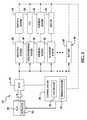
- FIG. 2is a schematic view of the turf maintenance vehicle of FIG. 1 ;
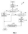
- FIG. 3is a flowchart illustrating a process of controlling the turf maintenance vehicle of FIG. 1 .
- a turf maintenance vehicle 10i.e., a grounds keeping vehicle
- the turf maintenance vehicle 10is a riding mower for cutting grass and other turf maintenance operations.
- the vehicle 10could be of any suitable type, including a walk-behind mower or any other type of turf maintenance vehicle, without departing from the scope of the present disclosure.
- the vehicle 10generally includes a frame 12 .
- the vehicle 10also includes a ground traction system 14 that supports the frame 12 and propels the vehicle 10 .
- the ground traction system 14includes a plurality of wheels 16 a , 16 b , 18 , including a left front wheel 16 a , a right front wheel 16 b , and a rear wheel 18 .
- the ground traction system 14could include any suitable configuration including any suitable number of wheels.
- the front wheels 16 a , 16 bprovide propulsion for the vehicle 10 . More specifically, the ground traction system 14 includes a left front propulsion motor 20 a and a right front propulsion motor 20 b .
- the left front propulsion motor 20 ais operatively connected to the left front wheel 16 a
- the right front propulsion motor 20 bis operatively connected to the right front wheel 16 b
- the propulsion motors 20 a , 20 bare electric motors powered by electricity as will be discussed in greater detail below. As such, when energy is delivered to the propulsion motors 20 a , 20 b , the propulsion motors 20 a , 20 b drivingly rotate the respective wheels 16 a , 16 b so as to propel the vehicle 10 .
- the propulsion motors 20 a , 20 bindependently drivingly rotate the respective wheels 16 a , 16 b ; however, the vehicle 10 could include an axle that rotatably couples the left front wheel 16 a and the right front wheel 16 b , and a single electric motor could drivingly rotate the axle to thereby propel the vehicle 10 .
- the vehicle 10could also include any suitable transmission for gear reduction purposes.
- the ground traction system 14further includes a speed control device 17 and a position sensor 19 .
- the speed control device 17can be of any suitable type, such as an accelerator pedal, a joystick, a lever, and the like.
- the operator(not shown) can actuate the speed control device 17 by foot to thereby change the speed of the vehicle 10 . For instance, pressing the speed control device 17 further forward increases the speed of the vehicle 10 .
- the vehicle 10could include any suitable accelerator input device other than a pedal, such as a hand-operated lever and the like.
- the position sensor 19detects a position of the speed control device 17 in order to change the power delivery to the propulsion motors 20 a , 20 b as will be described.
- the position sensor 19can be of any suitable type, such as a potentiometer, a Hall Effect sensor, and the like.
- the vehicle 10further includes a brake system (not shown) for reducing the ground speed of the vehicle 10 .
- the vehicle 10includes an operator seat 24 .
- the operator seat 24is mounted on the frame 12 and provides a place for the operator (not shown) to sit and operate the various subsystems of the vehicle 10 .
- the vehicle 10further includes a steering system, generally indicated at 26 .
- the steering system 26is a drive-by-wire system, and only the rear wheel 18 is steered.
- the vehicle 10could include any suitable steering system, including a steering system with mechanical couplings between the steering implement and the steered wheel.
- the vehicle 10could include any number of steered wheels.
- the steering system 26includes a steering wheel 28 provided in front of the operator seat 24 .
- the steering system 26also includes a shaft 30 rotatably fixed to the steering wheel 28 .
- the steering system 26additionally includes a steering angle sensor 32 operatively coupled to the shaft 30 for detecting a steering angle (i.e., a turning angle) of the shaft 30 and the steering wheel 28 .
- the steering system 26includes an actuator system 34 operatively coupled to the rear wheel 18 for changing the turning angle of the rear wheel 18 .
- the actuator system 34changes the turning angle of the rear wheel 18 based on the steering angle detected by the steering angle sensor 32 .
- the actuator system 34includes a motor 36 that outputs mechanical energy to change the steering angle of the rear wheel 18 .
- the actuator system 34can also include any appropriate gearing, linkages, and the like for operatively coupling the motor 36 and the rear wheel 18 .
- the motor 36 of the actuator system 34outputs energy to turn (i.e., steer) the rear wheel 18 depending on the steering angle detected by the steering angle sensor 32 .
- the motor 36 of the actuator system 34is an electric motor powered by electricity. It will also be appreciated that the steering system could include a hydraulic system for steering purposes or any other suitable components without departing from the scope of the present disclosure.
- the vehicle 10additionally includes a turf maintenance implement system, generally indicated at 38 .
- the turf maintenance implement system 38is generally used for turf maintenance purposes, such as grass cutting, fertilizing, material reduction, and the like.
- the turf maintenance implement system 38includes a plurality of cutting implements, namely a plurality of front cutters 40 a and a rear cutter 40 b .
- the cutters 40 a , 40 bare reel-type cutters; however, it will be appreciated that the cutters 40 a , 40 b could be of any suitable type without departing from the scope of the present disclosure.
- the turf maintenance implement system 38includes a plurality of cutter motors 42 , each operatively coupled to a respective cutter 40 a , 40 b .
- the cutter motors 42are each electric motors that are powered by electricity. When electric energy is delivered to the cutter motors 42 , the cutter motors 42 actuate the respective cutters 40 a , 40 b to drivingly rotate the respective cutter 40 a , 40 b.
- the turf maintenance implement system 38includes a plurality of lift motors 44 .
- Each of the lift motors 44is operatively coupled to a respective cutter 40 a , 40 b , to change a vertical position of the respective cutter 40 a , 40 b .
- the lift motors 44are electric motors powered by electricity.
- the lift motors 44actuate the respective cutter 40 a , 40 b , such that the cutters 40 a , 40 b can be lifted (e.g., for higher speed travel) or lowered (e.g., for cutting operations).
- the turf maintenance implement system 38further includes at least one power take-off switch 39 that selectively operates the cutter motors 42 and/or the lift motors 44 to thereby selectively operate the turf maintenance implement system 38 . More specifically, the operator (not shown) can turn the cutter motors 42 on and off and/or can turn the lift motors 44 on and off using the power take-off switch 39 . It will be appreciated that the vehicle 10 could include a plurality of power take-off switches 39 .
- the power take-off switch 39can be of any suitable known type.
- the turf maintenance vehicle 10additionally includes an accessory system 41 .
- the accessory system 41could include any number and any type of accessory that is indirectly related to turf maintenance purposes.
- the accessory system 41includes a head lamp 43 .
- the head lamp 43is fixed to the frame 12 at a forward position of the vehicle 10 , and the head lamp 43 illuminates the forward path of the vehicle 10 .
- the head lamp 43is an electric head lamp 43 and is powered by electricity.
- the accessory system 41includes a switch 45 .
- the switch 45is an on/off switch; however, it will be appreciated that the switch 45 could be of any suitable type.
- the switch 45can be manipulated by the operator in order to selectively turn the head lamp 43 on and off.
- the accessory system 41can also include one or more gauges, lights, and the like for displaying the status of the vehicle 10 to the operator.
- the vehicle 10includes a control system, generally indicated at 46 .
- the control system 46includes a controller 48 , which includes circuitry and programmed logic.
- the controller 48is the main controller for governing all operations of the vehicle 10 .
- the control system 46further includes a demand sensor 49 , which detects the electrical demand of the traction system 14 , the turf maintenance implement system 38 , the steering system 26 , and the accessory system 41 .
- the control system 46is in communication with the position sensor 19 , the power take-off switch 39 , the steering sensor 32 , and the switch 45 .
- the demand sensor 49 of the control system 46is able to detect an electrical demand of the traction system 14 , the turf maintenance implement system 38 , the steering system 26 , and the accessory system 41 , respectively, as will be described in greater detail below. More specifically, during operation, the position sensor 19 , the power take-off switch 39 , the steering sensor 32 , and/or the switch 45 transmit signals to the demand sensor 49 of the control system 46 , which correlate to electrical needs of these systems 14 , 38 , 26 , 41 .
- the controller 48causes power delivery to the traction system 14 , the turf maintenance implement system 38 , the steering system 26 , and/or the accessory system 41 to thereby meet the detected electrical demand.
- the controller 48relies on a signal feedback system for proper energy delivery to the systems 14 , 38 , 26 , 41 of the vehicle.
- the demand sensor 49could be configured to detect electrical demand of other systems of the vehicle 10 that are not illustrated without departing from the scope of the present disclosure.
- the vehicle 10further includes an internal combustion engine 50 .
- the internal combustion engine 50can be of any suitable known type, such as a gasoline or diesel engine.
- the vehicle 10includes an actuator system 52 , which is operatively coupled to the internal combustion engine 50 .
- the actuator system 52could be of any suitable known type for selectively changing the speed range of the engine 50 , such as a throttle system and/or a speed governor system.
- the actuator system 52can include an electromechanical actuator that is electrically driven by the controller 48 .
- the actuator system 52includes a butterfly valve or plate (not shown) on the carburetor of the engine 50 . As such, the actuator system 52 controls the amount by which the butterfly moves to expose the ports in the throat of the carburetor.
- a different actuator system 52can be used, for example, a mechanical linkage, together with a mechanical governor control arrangement in the case of a diesel engine. It will also be appreciated that the actuator system 52 could change the speed range of the engine 50 by selectively changing only the top speed or lowest speed (i.e., idle speed). Moreover, in some embodiments, the actuator system 52 changes the speed range of the engine 50 by changing air flow rate to the engine 50 , fuel flow to the engine 50 , and/or spark timing of the engine 50 . Furthermore, it will be appreciated that the speed range of the engine 50 could be selectively changed without an actuator system 52 , such as with an electrically-based (e.g., logic-based) system, for instance, for changing the spark timing of the engine 50 .
- an electrically-basede.g., logic-based
- the vehicle 10additionally includes an energy converting device 54 .
- the energy converting device 54is operatively coupled to the internal combustion engine 50 to convert mechanical energy from the internal combustion engine 50 to electric energy. More specifically, the internal combustion engine 50 includes an output shaft that is rotated due to combustion of fuel, and this mechanical energy is converted by the energy converting device 54 into electricity in a known manner.
- the energy converting device 54outputs current between 0-180 amps according to the electrical demand, in one embodiment.
- the energy converting device 54can be of any suitable type, including any known type of generator or alternator. As shown in FIG. 2 , the energy converting device 54 is in electrical communication with the traction system 14 , the turf maintenance implement system 38 , the steering system 26 , and the accessory system 41 .
- the systems 14 , 38 , 26 , 41are each powered by electric energy from the energy converting device 54 .
- each of the systems 14 , 38 , 26 , 41is electrically powered in the embodiment shown, it will be appreciated that less than all of the systems 14 , 38 , 26 , 41 of the vehicle 10 can be electrically powered. It will also be appreciated that other systems of the vehicle 10 that are not illustrated can be powered by the energy converting device 54 without departing from the scope of the present disclosure.
- the energy converting device 54outputs an amount of electricity based on the speed of the internal combustion engine 50 . Specifically, as the speed of the internal combustion engine 50 increases, the energy converting device 54 outputs a higher voltage, and as the internal combustion engine 50 reduces in speed, the energy converting device 54 outputs a lower voltage.
- control system 46changes the speed of the internal combustion engine 50 based on the electrical demand of the traction system 14 , turf maintenance implement system 38 , steering system 26 , accessory system 41 , and/or the energy storage system 56 , such that the electrical demand of the systems of vehicle 10 can be adequately met. More specifically, the demand sensor 49 detects the electrical demand of the traction system 14 via the position of the speed control device 17 detected by the position sensor 19 , the electrical demand of the turf maintenance implement system 38 via the configuration of the power take-off switch 39 , the electrical demand of the steering system 26 via steering signals from the steering sensor 32 , and the electrical demand of the accessory system 41 via the configuration of the switch 45 .
- the demand sensor 49outputs an electrical demand signal correlating to the detected electrical demand from each of the systems 14 , 38 , 26 , 41 .
- the controller 48receives the electrical demand signal and outputs a control signal, which causes the actuator system 52 to actuate to change the speed range of the internal combustion engine 50 based on the detected electrical demand. As a result, the operating voltage range of the energy converting device 54 changes to meet the detected electrical demand.
- the vehicle 10includes an energy storage device, generally indicated at 56 .
- the energy storage device 56includes at least one battery 58 .
- the vehicle 10includes a plurality of batteries 58 .
- the energy storage device 56includes a plurality of capacitors.
- the battery 58stores energy, and selectively outputs electricity to the traction system 14 , the turf maintenance implement system 38 , the steering system 26 and/or the accessory system 41 to supplement electricity output from the energy converting device 54 as will be described.
- the battery 58can be recharged by the energy converting device 54 . In other words, electricity from the energy converting device 54 can flow to the battery 58 to thereby recharge the battery 58 .
- the battery 58is automatically recharged by the energy converting device 54 when the battery 58 outputs supplemental energy to the systems 14 , 38 , 26 , 41 .
- the demand sensor 49is also in communication with the energy storage system 56 .
- the demand sensor 49detects when the battery 58 is being recharged by the energy converting device 54 to thereby detect an increased energy demand from the battery 58 as will be explained in greater detail below.
- the controller 48when electrical demand from the traction system 14 , turf maintenance implement system 38 , steering system 26 , accessory system 41 , and/or energy storage system 56 is low (e.g., when the vehicle 10 is at rest, the turf maintenance implement system 38 is off, etc.), the controller 48 causes the speed of the internal combustion engine 50 to reduce from a first speed range to a second speed range.
- the first speed rangei.e., normal operating speed range
- the second speed rangei.e., reduced operating speed range
- the second speed rangeis between approximately 1200 rpm and 1500 rpm, and for a gas engine, the second speed range has an average of approximately 2200 rpm with minimal fluctuation.
- the idle speed of the engine 50is reduced when the detected electrical demand is low.
- the operating voltage output from the energy converting device 54is reduced from a first operating voltage range to a second operating voltage range.
- the first operating voltage range (i.e., normal operating voltage range) of the energy converting device 54is between approximately 48 volts and 52 volts
- the second operating voltage rangei.e., reduced operating voltage rage
- the demand sensor 49detects a high electrical demand (e.g., when the vehicle 10 is traveling uphill, increased acceleration is detected from the position sensor 19 of the traction system 14 , the power take-off switch 39 is on such that the cutters 40 a , 40 b are operating, the power take-off switch 39 is set such that the lift motors 44 are operating, the steering sensor 32 indicates steering changes by the operator of the steering system 26 , and/or the switch 45 is set such that the head lamp 43 is on), then the controller 48 causes the internal combustion engine 50 to increase from a first speed range to a third speed range.
- a high electrical demande.g., when the vehicle 10 is traveling uphill, increased acceleration is detected from the position sensor 19 of the traction system 14 , the power take-off switch 39 is on such that the cutters 40 a , 40 b are operating, the power take-off switch 39 is set such that the lift motors 44 are operating, the steering sensor 32 indicates steering changes by the operator of the steering system 26 , and/or the switch 45 is set
- the first speed rangei.e., normal operating speed range
- the third speed rangei.e., increased speed range
- the first operating voltage rangeis between approximately 48 and 52 volts
- the third operating voltage rangeis between approximately 55 and 60 volts.
- the upper voltage limit of the third operating voltage rangeis limited by increasing the power output from the energy converting device 54 .
- the upper voltage limit from the energy converting device 54is limited to a maximum of 60 volts by increasing the amperage to approximately 180 amps.
- the battery 58selectively outputs electricity to supplement the electric energy from the energy converting device 54 when the demand sensor 49 detects a high energy demand from the systems 14 , 38 , 26 , 41 .
- the energy converting device 54is able to output approximately 5.5 kW, and the battery 58 outputs supplemental electricity when the electrical demand from the systems 14 , 38 , 26 , 41 exceeds the capacity of the energy converting device 54 .
- the controller 48outputs a control signal to the energy storage system to selectively cause the battery 58 to output supplemental electricity.
- the control system 46causes the energy converting device 54 to output energy to the battery 58 to recharge the battery 58 .
- the energy converting device 54immediately beings recharging the battery 58 once the battery 58 begins outputting supplemental electricity.
- the energy storage system 56includes a charge sensor (not shown), and the energy converting device 54 begins outputting energy to recharge the battery 58 when the charge sensor detects that the charge of the battery 58 falls below a predetermined level.
- the controller 48when the electrical demand is high, then the controller 48 causes the internal combustion engine 50 to increase from the first speed range to the third speed range.
- the controller 48increases the speed range of the engine 50 from the first speed range to the third speed range.
- the energy converting device 54meets the electrical demand of the systems 14 , 38 , 26 , 41 as well as the recharging needs of the battery 58 .
- the method 80begins at 82 , in which the demand sensor 49 detects the electrical demand of the traction system 14 , the turf maintenance implement system 38 , the steering system 26 , the accessory system 41 and/or the energy storage system 56 .
- decision block 84it is determined whether the detected demand is below a predetermined level X. If the detected demand is below the predetermined level X, the method 80 continues at 86 , in which the speed range of the internal combustion engine 50 is reduced as described above. However, if the electrical demand is not below the predetermined level X, the method 80 moves to decision block 88 , in which it is determined whether the electrical demand is above the predetermined level Y.
- the method 80ends; however, if the detected demand is above the predetermined level Y, the method 80 moves to 90 .
- the controller 48causes the battery 58 to output supplemental electricity to the systems 14 , 38 , 26 , 41 of the vehicle 10 .
- the controller 48increases the speed range of the internal combustion engine 50 to increase and causes the energy converting device 54 to output energy to the battery 58 to thereby recharge the battery 58 in addition to outputting energy to the systems 14 , 38 , 26 , 41 of the vehicle 10 .
- the performance and efficiency of the vehicle 10can be improved using the method 80 and the control system 46 described above.
- the engine speedcan be reduced to thereby reduce fuel consumption and reduce operating noise while still meeting the electrical demand of the vehicle 10 .
- the speed of the internal combustion engine 50can be increased selectively to meet the increased electrical demand of the vehicle 10 .
- Response time for this systemcan be relatively low as well (e.g., approximately 0.25 seconds) for improved performance of the vehicle 10 .
- control system 46changed the speed range of the engine 50 between three ranges, the control system 46 could change the speed range of the engine 50 between any number of ranges. It will also be appreciated that the control system 46 could change the operating voltage output from the energy converting device 54 between any number of ranges. Furthermore, it will be appreciated that the speed ranges of the engine 50 and the operating voltages output by the energy converting device 54 could have any suitable numerical range.
- the demand sensor 49can detect electrical demand from the systems 14 , 38 , 26 , 41 , 58 in any suitable fashion. For instance, instead of detecting energy demand from the steering system 26 via the steering sensor 32 , the demand sensor 49 could detect energy demand via the steering motor 36 .
Landscapes
- Life Sciences & Earth Sciences (AREA)
- Environmental Sciences (AREA)
- Engineering & Computer Science (AREA)
- Power Engineering (AREA)
- Transportation (AREA)
- Mechanical Engineering (AREA)
- Control Of Vehicle Engines Or Engines For Specific Uses (AREA)
- Control Of Charge By Means Of Generators (AREA)
- Electric Propulsion And Braking For Vehicles (AREA)
- Harvester Elements (AREA)
- Hybrid Electric Vehicles (AREA)
Abstract
Description
Claims (21)
Priority Applications (3)
| Application Number | Priority Date | Filing Date | Title |
|---|---|---|---|
| US12/020,854US7735592B2 (en) | 2008-01-28 | 2008-01-28 | Regulated output voltage generator-set applied to mobile equipment in the turf industry |
| EP08253571.7AEP2082641B1 (en) | 2008-01-28 | 2008-10-31 | Turf maintenance vehicle with electrical demand sensor and method of operation |
| JP2009013656AJP5337503B2 (en) | 2008-01-28 | 2009-01-23 | Regulated output voltage generator applied to mobile equipment in the lawn industry |
Applications Claiming Priority (1)
| Application Number | Priority Date | Filing Date | Title |
|---|---|---|---|
| US12/020,854US7735592B2 (en) | 2008-01-28 | 2008-01-28 | Regulated output voltage generator-set applied to mobile equipment in the turf industry |
Publications (2)
| Publication Number | Publication Date |
|---|---|
| US20090188227A1 US20090188227A1 (en) | 2009-07-30 |
| US7735592B2true US7735592B2 (en) | 2010-06-15 |
Family
ID=40612957
Family Applications (1)
| Application Number | Title | Priority Date | Filing Date |
|---|---|---|---|
| US12/020,854Active2029-01-11US7735592B2 (en) | 2008-01-28 | 2008-01-28 | Regulated output voltage generator-set applied to mobile equipment in the turf industry |
Country Status (3)
| Country | Link |
|---|---|
| US (1) | US7735592B2 (en) |
| EP (1) | EP2082641B1 (en) |
| JP (1) | JP5337503B2 (en) |
Cited By (22)
| Publication number | Priority date | Publication date | Assignee | Title |
|---|---|---|---|---|
| US20110061355A1 (en)* | 2009-09-16 | 2011-03-17 | Griffin Randall J | Grass mowing machine with engine speed and voltage limiter |
| US8621833B2 (en)* | 2010-01-13 | 2014-01-07 | Ihi Corporation | Lawn mowing vehicle with a control unit for the motor |
| US20140283492A1 (en)* | 2013-03-15 | 2014-09-25 | The Toro Company | Hybrid electric turf mower with power shed and power boost |
| US20140331630A1 (en)* | 2013-05-10 | 2014-11-13 | Deere & Company | End of cut speed control system |
| US20150120148A1 (en)* | 2013-10-31 | 2015-04-30 | Deere & Company | Electric implement power management system |
| US9499199B1 (en) | 2014-04-23 | 2016-11-22 | Hydro-Gear Limited Partnership | Hybrid vehicle |
| US9872438B2 (en) | 2013-03-15 | 2018-01-23 | Mtd Products Inc | Battery-electric and internal-combustion engine assist hybrid propulsion and implement drive work systems |
| US10063097B2 (en) | 2015-10-16 | 2018-08-28 | Kohler Co. | Segmented waveform converter on controlled field variable speed generator |
| US10148207B2 (en) | 2015-10-16 | 2018-12-04 | Kohler Co. | Segmented waveform converter on controlled field variable speed generator |
| US10148202B2 (en) | 2015-10-16 | 2018-12-04 | Kohler Co. | Hybrid device with segmented waveform converter |
| US10778123B2 (en) | 2015-10-16 | 2020-09-15 | Kohler Co. | Synchronous inverter |
| US11014549B1 (en) | 2016-01-04 | 2021-05-25 | Hydro-Gear Limited Partnership | Regeneration power control |
| US20220408648A1 (en)* | 2021-06-25 | 2022-12-29 | Nanjing Chervon Industry Co., Ltd. | Outdoor walking equipment |
| US11547042B2 (en) | 2020-02-26 | 2023-01-10 | Deere & Company | Adaptive engine speed control system |
| US11591978B1 (en)* | 2022-05-13 | 2023-02-28 | Caterpillar Inc. | Speed control for a mobile machine |
| US20230122499A1 (en)* | 2019-10-11 | 2023-04-20 | Ariens Company | Power source and control system for a lawn mower |
| US11641795B2 (en) | 2018-09-27 | 2023-05-09 | Nanjing Chervon Industry Co., Ltd. | Lawn mower |
| USD987691S1 (en) | 2018-09-27 | 2023-05-30 | Nanjing Chervon Industry Co., Ltd. | Mower blade assembly |
| USD995569S1 (en) | 2019-04-18 | 2023-08-15 | Nanjing Chervon Industry Co., Ltd. | Mower blade assembly |
| US11910752B2 (en) | 2017-12-28 | 2024-02-27 | Nanjing Chervon Industry Co., Ltd. | Electric riding lawn mower |
| US12342761B2 (en) | 2017-12-28 | 2025-07-01 | Nanjing Chervon Industry Co., Ltd. | Outdoor moving device |
| US12439854B2 (en) | 2021-06-25 | 2025-10-14 | Nanjing Chervon Industry Co., Ltd. | Outdoor walking equipment |
Families Citing this family (10)
| Publication number | Priority date | Publication date | Assignee | Title |
|---|---|---|---|---|
| JP5783678B2 (en)* | 2010-01-13 | 2015-09-24 | 株式会社Ihi | Lawn mower |
| JP5658880B2 (en)* | 2010-01-13 | 2015-01-28 | 株式会社Ihi | Lawn mower |
| JP5829794B2 (en)* | 2010-01-13 | 2015-12-09 | 株式会社Ihi | Lawn mower |
| JP5771356B2 (en)* | 2010-01-13 | 2015-08-26 | 株式会社Ihi | Riding lawn mower |
| CN104663110A (en)* | 2014-12-03 | 2015-06-03 | 宁波大叶园林设备有限公司 | Lawn mower with engine with LPG (liquid propane gas) fuel tank unit and production method of LPG fuel tank unit |
| CN104541738A (en)* | 2014-12-04 | 2015-04-29 | 宁波大叶园林设备有限公司 | Lawn mower using engine with LPG (Liquefied Petroleum Gas) fuel tank |
| JP7201203B2 (en)* | 2018-06-27 | 2023-01-10 | 株式会社ササキコーポレーション | Self-propelled work machine and control system for self-propelled work machine |
| WO2023196856A2 (en)* | 2022-04-05 | 2023-10-12 | Ariens Company | Multi-configuration work vehicle |
| US12297742B2 (en) | 2022-05-31 | 2025-05-13 | Huaneng Taiyuan Dongshan Gas Turbine Cogeneration Co., Ltd | Safety control method and system for generator of gas turbine power plant |
| CN114696691B (en)* | 2022-05-31 | 2022-09-02 | 华能太原东山燃机热电有限责任公司 | Safety control method and system for generator of gas turbine power plant |
Citations (12)
| Publication number | Priority date | Publication date | Assignee | Title |
|---|---|---|---|---|
| US5417193A (en) | 1994-01-25 | 1995-05-23 | Textron Inc. | Engine speed control system and method |
| US5497604A (en)* | 1994-02-03 | 1996-03-12 | The Toro Company | Supervisor switch for turf mower |
| US5549089A (en) | 1995-08-08 | 1996-08-27 | Textron Inc. | Engine maximum speed limiter |
| US5794422A (en) | 1995-11-13 | 1998-08-18 | Ransomes America Corporation | Electric drive mower with motor generator set |
| US5934051A (en) | 1997-02-06 | 1999-08-10 | Textron, Inc. | Solid state mow system for electrically powered mower |
| US6082084A (en) | 1995-11-13 | 2000-07-04 | Ransomes America Corporation | Electric riding mower with electric steering system |
| US6138528A (en)* | 1999-05-18 | 2000-10-31 | Kubota Corporation | Agricultural tractor |
| US6571542B1 (en) | 1999-03-25 | 2003-06-03 | Textron Inc. | Electric drive mower with interchangeable power sources |
| EP0959660B1 (en) | 1996-02-09 | 2003-06-25 | The Toro Company | Electric drive riding mower |
| US6591593B1 (en)* | 2000-10-23 | 2003-07-15 | Dennis Brandon | Electric riding lawn mower powered by an internal combustion engine and generator system |
| US6892517B2 (en)* | 2003-02-12 | 2005-05-17 | Tecumseh Products Company | Blade and ground speed control system |
| US7367173B2 (en)* | 2005-03-02 | 2008-05-06 | Textron Inc. | Greens mower data display and controller |
Family Cites Families (6)
| Publication number | Priority date | Publication date | Assignee | Title |
|---|---|---|---|---|
| JPH08308020A (en)* | 1995-05-02 | 1996-11-22 | Hino Motors Ltd | Auxiliary accelerator and auxiliary braking device |
| JP2001090572A (en)* | 1999-09-28 | 2001-04-03 | Yamaha Motor Co Ltd | Series hybrid electric-powered vehicle |
| JP4090704B2 (en)* | 2001-04-27 | 2008-05-28 | 株式会社神戸製鋼所 | Power control device for hybrid type work machine |
| JP4085767B2 (en)* | 2002-10-07 | 2008-05-14 | 日産自動車株式会社 | Control device for vehicle generator |
| US6948299B2 (en)* | 2002-11-22 | 2005-09-27 | Honda Motor Company, Ltd. | Hybrid power equipment |
| JP4578434B2 (en)* | 2006-05-24 | 2010-11-10 | 本田技研工業株式会社 | Self-propelled work machine load control mechanism |
- 2008
- 2008-01-28USUS12/020,854patent/US7735592B2/enactiveActive
- 2008-10-31EPEP08253571.7Apatent/EP2082641B1/enactiveActive
- 2009
- 2009-01-23JPJP2009013656Apatent/JP5337503B2/ennot_activeExpired - Fee Related
Patent Citations (19)
| Publication number | Priority date | Publication date | Assignee | Title |
|---|---|---|---|---|
| US5417193A (en) | 1994-01-25 | 1995-05-23 | Textron Inc. | Engine speed control system and method |
| US5497604A (en)* | 1994-02-03 | 1996-03-12 | The Toro Company | Supervisor switch for turf mower |
| US5549089A (en) | 1995-08-08 | 1996-08-27 | Textron Inc. | Engine maximum speed limiter |
| US6644004B2 (en) | 1995-11-13 | 2003-11-11 | Textron Inc. | Electric riding mower with motor generator set and noise abatement |
| US5794422A (en) | 1995-11-13 | 1998-08-18 | Ransomes America Corporation | Electric drive mower with motor generator set |
| US6082084A (en) | 1995-11-13 | 2000-07-04 | Ransomes America Corporation | Electric riding mower with electric steering system |
| US6857253B2 (en) | 1995-11-13 | 2005-02-22 | Ransomes America Corporation | Electric riding mower with motor generator set and noise abatement |
| US6449934B1 (en) | 1995-11-13 | 2002-09-17 | Ransomes America Corporation | Electric riding mower with motor generator set and noise abatement |
| EP0959660B1 (en) | 1996-02-09 | 2003-06-25 | The Toro Company | Electric drive riding mower |
| US5934051A (en) | 1997-02-06 | 1999-08-10 | Textron, Inc. | Solid state mow system for electrically powered mower |
| US6571542B1 (en) | 1999-03-25 | 2003-06-03 | Textron Inc. | Electric drive mower with interchangeable power sources |
| US6729114B2 (en) | 1999-03-25 | 2004-05-04 | Textron Inc. | Electric drive mower with trailed auxiliary power source |
| US6938400B2 (en) | 1999-03-25 | 2005-09-06 | Textron Inc. | Electric drive mower with trailed auxiliary power source |
| US20050230168A1 (en) | 1999-03-25 | 2005-10-20 | Fillman Alan R | Electric drive mower with trailed auxiliary power source |
| US6138528A (en)* | 1999-05-18 | 2000-10-31 | Kubota Corporation | Agricultural tractor |
| US6591593B1 (en)* | 2000-10-23 | 2003-07-15 | Dennis Brandon | Electric riding lawn mower powered by an internal combustion engine and generator system |
| US6892517B2 (en)* | 2003-02-12 | 2005-05-17 | Tecumseh Products Company | Blade and ground speed control system |
| US7275355B2 (en)* | 2003-02-12 | 2007-10-02 | Tecumseh Products Company | Blade and ground speed control system |
| US7367173B2 (en)* | 2005-03-02 | 2008-05-06 | Textron Inc. | Greens mower data display and controller |
Cited By (52)
| Publication number | Priority date | Publication date | Assignee | Title |
|---|---|---|---|---|
| US20110061355A1 (en)* | 2009-09-16 | 2011-03-17 | Griffin Randall J | Grass mowing machine with engine speed and voltage limiter |
| US8621833B2 (en)* | 2010-01-13 | 2014-01-07 | Ihi Corporation | Lawn mowing vehicle with a control unit for the motor |
| US8839598B2 (en) | 2010-01-13 | 2014-09-23 | Ihi Corporation | Lawn mowing vehicle with a control unit for elevating mechanisms |
| US9084391B2 (en) | 2010-01-13 | 2015-07-21 | Ihi Corporation | Lawn mowing vehicle with a control unit for elevating mechanisms and for rotating a blade depending on grass condition |
| US9113596B2 (en)* | 2013-03-15 | 2015-08-25 | The Toro Company | Hybrid electric turf mower with power shed and power boost |
| US20140283492A1 (en)* | 2013-03-15 | 2014-09-25 | The Toro Company | Hybrid electric turf mower with power shed and power boost |
| US9872438B2 (en) | 2013-03-15 | 2018-01-23 | Mtd Products Inc | Battery-electric and internal-combustion engine assist hybrid propulsion and implement drive work systems |
| US9179596B2 (en)* | 2013-05-10 | 2015-11-10 | Deere & Company | End of cut speed control system |
| US20140331630A1 (en)* | 2013-05-10 | 2014-11-13 | Deere & Company | End of cut speed control system |
| US9475497B2 (en)* | 2013-10-31 | 2016-10-25 | Deere & Company | Electric implement power management system |
| US20150120148A1 (en)* | 2013-10-31 | 2015-04-30 | Deere & Company | Electric implement power management system |
| US10577019B1 (en) | 2014-04-23 | 2020-03-03 | Hydro-Gear Limited Partnership | Hybrid vehicle |
| US9499199B1 (en) | 2014-04-23 | 2016-11-22 | Hydro-Gear Limited Partnership | Hybrid vehicle |
| US11938997B1 (en) | 2014-04-23 | 2024-03-26 | Hydro-Gear Limited Partnership | Vehicle having electric drive and operator platform |
| US11001299B1 (en) | 2014-04-23 | 2021-05-11 | Hydro-Gear Limited Partnership | Vehicle having electric drive and operator platform |
| US10150503B1 (en) | 2014-04-23 | 2018-12-11 | Hydro-Gear Limited Partnership | Hybrid vehicle |
| US10148202B2 (en) | 2015-10-16 | 2018-12-04 | Kohler Co. | Hybrid device with segmented waveform converter |
| US10148207B2 (en) | 2015-10-16 | 2018-12-04 | Kohler Co. | Segmented waveform converter on controlled field variable speed generator |
| US10903764B2 (en) | 2015-10-16 | 2021-01-26 | Kohler, Co. | Synchronous inverter |
| US10063097B2 (en) | 2015-10-16 | 2018-08-28 | Kohler Co. | Segmented waveform converter on controlled field variable speed generator |
| US10778123B2 (en) | 2015-10-16 | 2020-09-15 | Kohler Co. | Synchronous inverter |
| US12368399B2 (en) | 2015-10-16 | 2025-07-22 | Discovery Energy, Llc | Synchronous inverter |
| US11014549B1 (en) | 2016-01-04 | 2021-05-25 | Hydro-Gear Limited Partnership | Regeneration power control |
| US11679753B1 (en) | 2016-01-04 | 2023-06-20 | Hydro-Gear Limited Partnership | Regeneration power control |
| US12179739B1 (en) | 2016-01-04 | 2024-12-31 | Hydro-Gear Limited Partnership | Regeneration power control |
| US12364202B2 (en) | 2017-12-28 | 2025-07-22 | Nanjing Chervon Industry Co., Ltd. | Electric riding lawn mower |
| US12356892B2 (en) | 2017-12-28 | 2025-07-15 | Nanjing Chervon Industry Co., Ltd. | Electric riding lawn mower |
| US12342761B2 (en) | 2017-12-28 | 2025-07-01 | Nanjing Chervon Industry Co., Ltd. | Outdoor moving device |
| US12364201B2 (en) | 2017-12-28 | 2025-07-22 | Nanjing Chervon Industry Co., Ltd. | Electric riding lawn mower |
| US12317778B2 (en) | 2017-12-28 | 2025-06-03 | Nanjing Chervon Industry Co., Ltd. | Electric riding lawn mower |
| US11910752B2 (en) | 2017-12-28 | 2024-02-27 | Nanjing Chervon Industry Co., Ltd. | Electric riding lawn mower |
| USD987691S1 (en) | 2018-09-27 | 2023-05-30 | Nanjing Chervon Industry Co., Ltd. | Mower blade assembly |
| US11641795B2 (en) | 2018-09-27 | 2023-05-09 | Nanjing Chervon Industry Co., Ltd. | Lawn mower |
| USD996471S1 (en) | 2018-09-27 | 2023-08-22 | Nanjing Chervon Industry Co., Ltd. | Mower blade assembly |
| USD997998S1 (en) | 2018-09-27 | 2023-09-05 | Nanjing Chervon Industry Co., Ltd. | Mower blade |
| USD995567S1 (en) | 2018-09-27 | 2023-08-15 | Nanjing Chervon Industry Co., Ltd. | Mower blade assembly |
| US12408584B2 (en) | 2018-09-27 | 2025-09-09 | Nanjing Chervon Industry Co., Ltd. | Dual blade assembly for a lawn mower |
| US11917939B2 (en) | 2018-09-27 | 2024-03-05 | Nanjing Chervon Industry Co., Ltd. | Blade assembly for a lawn mower |
| US11937545B2 (en) | 2018-09-27 | 2024-03-26 | Nanjing Chervon Industry Co., Ltd. | Blade assembly for a lawn mower |
| USD995568S1 (en) | 2018-09-27 | 2023-08-15 | Nanjing Chervon Industry Co., Ltd. | Mower blade assembly |
| US11997944B2 (en) | 2018-09-27 | 2024-06-04 | Nanjing Chervon Industry Co., Ltd. | Blade assembly for a lawn mower |
| US12041874B2 (en) | 2018-09-27 | 2024-07-23 | Nanjing Chervon Industry Co., Ltd. | Blade assembly for a lawn mower |
| USD996470S1 (en) | 2018-09-27 | 2023-08-22 | Nanjing Chervon Industry Co., Ltd. | Mower blade assembly |
| USD995569S1 (en) | 2019-04-18 | 2023-08-15 | Nanjing Chervon Industry Co., Ltd. | Mower blade assembly |
| US20230182612A1 (en)* | 2019-10-11 | 2023-06-15 | Accelerated Systems, Inc. | Power source and control system for a lawn mower |
| US20230122499A1 (en)* | 2019-10-11 | 2023-04-20 | Ariens Company | Power source and control system for a lawn mower |
| US11547042B2 (en) | 2020-02-26 | 2023-01-10 | Deere & Company | Adaptive engine speed control system |
| US20220408648A1 (en)* | 2021-06-25 | 2022-12-29 | Nanjing Chervon Industry Co., Ltd. | Outdoor walking equipment |
| US11917945B2 (en) | 2021-06-25 | 2024-03-05 | Nanjing Chervon Industry Co., Ltd. | Outdoor moving device |
| US12433198B2 (en)* | 2021-06-25 | 2025-10-07 | Nanjing Chervon Industry Co., Ltd. | Outdoor walking equipment |
| US12439854B2 (en) | 2021-06-25 | 2025-10-14 | Nanjing Chervon Industry Co., Ltd. | Outdoor walking equipment |
| US11591978B1 (en)* | 2022-05-13 | 2023-02-28 | Caterpillar Inc. | Speed control for a mobile machine |
Also Published As
| Publication number | Publication date |
|---|---|
| JP2009174539A (en) | 2009-08-06 |
| US20090188227A1 (en) | 2009-07-30 |
| JP5337503B2 (en) | 2013-11-06 |
| EP2082641B1 (en) | 2017-04-19 |
| EP2082641A2 (en) | 2009-07-29 |
| EP2082641A3 (en) | 2016-03-23 |
Similar Documents
| Publication | Publication Date | Title |
|---|---|---|
| US7735592B2 (en) | Regulated output voltage generator-set applied to mobile equipment in the turf industry | |
| US7975786B2 (en) | Electric ground working vehicle | |
| US7017327B2 (en) | Hybrid electric tool carrier | |
| US6857253B2 (en) | Electric riding mower with motor generator set and noise abatement | |
| US6948299B2 (en) | Hybrid power equipment | |
| US4199037A (en) | Electric automobile | |
| US20080234096A1 (en) | Hybrid Utility Vehicle | |
| US20090000839A1 (en) | Riding lawn mower | |
| US7100312B2 (en) | Working machine | |
| US20100056326A1 (en) | Steering systems and methods for hybrid vehicles | |
| US20230202288A1 (en) | Crawler vehicle, control method and computer program of said vehicle | |
| EP1205338A2 (en) | Control elements for regulating engine speed, vehicle ground speed and power take-off (PTO) speed | |
| US6977473B2 (en) | Travel control method of electric vehicle | |
| US12179739B1 (en) | Regeneration power control | |
| US6968265B2 (en) | Travel control method of electric vehicle | |
| WO2019180850A1 (en) | Work machine | |
| GB2390837A (en) | Snowmobiles | |
| JP3528966B2 (en) | Work machine | |
| US12286181B2 (en) | Apparatus and system for seat replacements with multiple driving mode capabilities |
Legal Events
| Date | Code | Title | Description |
|---|---|---|---|
| AS | Assignment | Owner name:TEXTRON INC., RHODE ISLAND Free format text:ASSIGNMENT OF ASSIGNORS INTEREST;ASSIGNORS:BELLOT, CARLOS A.;CARLSON, MARTIN M.;WILSON, KENNETH R.;REEL/FRAME:020636/0658;SIGNING DATES FROM 20080303 TO 20080306 Owner name:TEXTRON INC.,RHODE ISLAND Free format text:ASSIGNMENT OF ASSIGNORS INTEREST;ASSIGNORS:BELLOT, CARLOS A.;CARLSON, MARTIN M.;WILSON, KENNETH R.;SIGNING DATES FROM 20080303 TO 20080306;REEL/FRAME:020636/0658 | |
| AS | Assignment | Owner name:TEXTRON INNOVATIONS INC., RHODE ISLAND Free format text:ASSIGNMENT OF ASSIGNORS INTEREST;ASSIGNORS:TEXTRON INC.;TEXTRON RHODE ISLAND;REEL/FRAME:023012/0526 Effective date:20090529 Owner name:TEXTRON INNOVATIONS INC.,RHODE ISLAND Free format text:ASSIGNMENT OF ASSIGNORS INTEREST;ASSIGNORS:TEXTRON INC.;TEXTRON RHODE ISLAND;REEL/FRAME:023012/0526 Effective date:20090529 | |
| STCF | Information on status: patent grant | Free format text:PATENTED CASE | |
| FPAY | Fee payment | Year of fee payment:4 | |
| MAFP | Maintenance fee payment | Free format text:PAYMENT OF MAINTENANCE FEE, 8TH YEAR, LARGE ENTITY (ORIGINAL EVENT CODE: M1552) Year of fee payment:8 | |
| MAFP | Maintenance fee payment | Free format text:PAYMENT OF MAINTENANCE FEE, 12TH YEAR, LARGE ENTITY (ORIGINAL EVENT CODE: M1553); ENTITY STATUS OF PATENT OWNER: LARGE ENTITY Year of fee payment:12 |