US7735493B2 - System and method for delivering a left atrial appendage containment device - Google Patents
System and method for delivering a left atrial appendage containment deviceDownload PDFInfo
- Publication number
- US7735493B2 US7735493B2US10/642,384US64238403AUS7735493B2US 7735493 B2US7735493 B2US 7735493B2US 64238403 AUS64238403 AUS 64238403AUS 7735493 B2US7735493 B2US 7735493B2
- Authority
- US
- United States
- Prior art keywords
- implant
- distal
- proximal
- axially moveable
- guide tube
- Prior art date
- Legal status (The legal status is an assumption and is not a legal conclusion. Google has not performed a legal analysis and makes no representation as to the accuracy of the status listed.)
- Active, expires
Links
- 210000005248left atrial appendageAnatomy0.000titleclaimsabstractdescription95
- 238000000034methodMethods0.000titledescription42
- 230000033001locomotionEffects0.000claimsabstractdescription63
- 239000007943implantSubstances0.000claimsdescription305
- 239000000463materialSubstances0.000claimsdescription21
- 230000003073embolic effectEffects0.000claimsdescription3
- 230000002829reductive effectEffects0.000abstractdescription24
- 230000013011matingEffects0.000description43
- 238000002347injectionMethods0.000description42
- 239000007924injectionSubstances0.000description42
- 239000003550markerSubstances0.000description24
- 230000004888barrier functionEffects0.000description21
- 239000012528membraneSubstances0.000description18
- 229940039231contrast mediaDrugs0.000description16
- 239000002872contrast mediaSubstances0.000description16
- 238000002594fluoroscopyMethods0.000description15
- 239000002131composite materialSubstances0.000description14
- 238000011068loading methodMethods0.000description13
- 206010003658Atrial FibrillationDiseases0.000description12
- 239000003381stabilizerSubstances0.000description12
- 230000006835compressionEffects0.000description11
- 238000007906compressionMethods0.000description11
- 230000008878couplingEffects0.000description11
- 238000010168coupling processMethods0.000description11
- 238000005859coupling reactionMethods0.000description11
- 239000004698PolyethyleneSubstances0.000description10
- 208000007536ThrombosisDiseases0.000description10
- 239000012530fluidSubstances0.000description9
- 229910052751metalInorganic materials0.000description9
- 239000002184metalSubstances0.000description9
- 229910001000nickel titaniumInorganic materials0.000description9
- 238000010276constructionMethods0.000description8
- 229920000295expanded polytetrafluoroethylenePolymers0.000description8
- 238000002513implantationMethods0.000description8
- 239000010935stainless steelSubstances0.000description8
- 229910001220stainless steelInorganic materials0.000description8
- 238000012800visualizationMethods0.000description8
- 239000000853adhesiveSubstances0.000description7
- 230000001070adhesive effectEffects0.000description7
- 238000005452bendingMethods0.000description7
- 238000003698laser cuttingMethods0.000description7
- 238000012360testing methodMethods0.000description7
- 208000006011StrokeDiseases0.000description6
- 230000004323axial lengthEffects0.000description6
- 230000007246mechanismEffects0.000description6
- 230000036961partial effectEffects0.000description6
- -1polyethylenePolymers0.000description6
- HZEWFHLRYVTOIW-UHFFFAOYSA-N[Ti].[Ni]Chemical compound[Ti].[Ni]HZEWFHLRYVTOIW-UHFFFAOYSA-N0.000description5
- 230000001746atrial effectEffects0.000description5
- 230000015572biosynthetic processEffects0.000description5
- 238000004891communicationMethods0.000description5
- 229920000573polyethylenePolymers0.000description5
- 230000000087stabilizing effectEffects0.000description5
- 238000005520cutting processMethods0.000description4
- 239000004744fabricSubstances0.000description4
- 238000004519manufacturing processMethods0.000description4
- 230000005012migrationEffects0.000description4
- 238000013508migrationMethods0.000description4
- 230000004048modificationEffects0.000description4
- 238000012986modificationMethods0.000description4
- HLXZNVUGXRDIFK-UHFFFAOYSA-Nnickel titaniumChemical compound[Ti].[Ti].[Ti].[Ti].[Ti].[Ti].[Ti].[Ti].[Ti].[Ti].[Ti].[Ni].[Ni].[Ni].[Ni].[Ni].[Ni].[Ni].[Ni].[Ni].[Ni].[Ni].[Ni].[Ni].[Ni]HLXZNVUGXRDIFK-UHFFFAOYSA-N0.000description4
- 239000004033plasticSubstances0.000description4
- 229920003023plasticPolymers0.000description4
- 229920000642polymerPolymers0.000description4
- 230000002792vascularEffects0.000description4
- 238000003466weldingMethods0.000description4
- FAPWRFPIFSIZLT-UHFFFAOYSA-MSodium chlorideChemical compound[Na+].[Cl-]FAPWRFPIFSIZLT-UHFFFAOYSA-M0.000description3
- 210000003484anatomyAnatomy0.000description3
- 239000008280bloodSubstances0.000description3
- 210000004369bloodAnatomy0.000description3
- 230000001413cellular effectEffects0.000description3
- 230000006870functionEffects0.000description3
- 210000005246left atriumAnatomy0.000description3
- 239000011148porous materialSubstances0.000description3
- 230000009467reductionEffects0.000description3
- 238000007789sealingMethods0.000description3
- 239000011780sodium chlorideSubstances0.000description3
- 239000007787solidSubstances0.000description3
- 238000013112stability testMethods0.000description3
- 206010014498Embolic strokeDiseases0.000description2
- 229920002614Polyether block amidePolymers0.000description2
- 239000000560biocompatible materialSubstances0.000description2
- 230000017531blood circulationEffects0.000description2
- 238000005219brazingMethods0.000description2
- 230000000747cardiac effectEffects0.000description2
- 210000000038chestAnatomy0.000description2
- 230000000295complement effectEffects0.000description2
- 239000004035construction materialSubstances0.000description2
- 238000013461designMethods0.000description2
- 229940079593drugDrugs0.000description2
- 239000003814drugSubstances0.000description2
- 238000002592echocardiographyMethods0.000description2
- 230000023597hemostasisEffects0.000description2
- 238000003780insertionMethods0.000description2
- 230000037431insertionEffects0.000description2
- 230000014759maintenance of locationEffects0.000description2
- 238000010079rubber tappingMethods0.000description2
- 238000004904shorteningMethods0.000description2
- 238000001356surgical procedureMethods0.000description2
- 210000002620vena cava superiorAnatomy0.000description2
- 208000005189EmbolismDiseases0.000description1
- 239000004812Fluorinated ethylene propyleneSubstances0.000description1
- 239000004696Poly ether ether ketoneSubstances0.000description1
- 208000012287ProlapseDiseases0.000description1
- 208000025747Rheumatic diseaseDiseases0.000description1
- 229910045601alloyInorganic materials0.000description1
- 239000000956alloySubstances0.000description1
- 238000004873anchoringMethods0.000description1
- 206010003119arrhythmiaDiseases0.000description1
- 230000006793arrhythmiaEffects0.000description1
- 238000010009beatingMethods0.000description1
- 230000009286beneficial effectEffects0.000description1
- 230000008901benefitEffects0.000description1
- JUPQTSLXMOCDHR-UHFFFAOYSA-Nbenzene-1,4-diol;bis(4-fluorophenyl)methanoneChemical compoundOC1=CC=C(O)C=C1.C1=CC(F)=CC=C1C(=O)C1=CC=C(F)C=C1JUPQTSLXMOCDHR-UHFFFAOYSA-N0.000description1
- 230000000903blocking effectEffects0.000description1
- 238000007675cardiac surgeryMethods0.000description1
- 230000010261cell growthEffects0.000description1
- 239000000919ceramicSubstances0.000description1
- 230000000739chaotic effectEffects0.000description1
- 238000003759clinical diagnosisMethods0.000description1
- 230000001010compromised effectEffects0.000description1
- 230000008602contractionEffects0.000description1
- 238000007796conventional methodMethods0.000description1
- 230000003247decreasing effectEffects0.000description1
- 238000006073displacement reactionMethods0.000description1
- 230000000694effectsEffects0.000description1
- 230000005489elastic deformationEffects0.000description1
- 229910000701elgiloys (Co-Cr-Ni Alloy)Inorganic materials0.000description1
- 230000008030eliminationEffects0.000description1
- 238000003379elimination reactionMethods0.000description1
- 238000001125extrusionMethods0.000description1
- 210000003191femoral veinAnatomy0.000description1
- 238000011049fillingMethods0.000description1
- 210000003811fingerAnatomy0.000description1
- 238000011010flushing procedureMethods0.000description1
- 239000003292glueSubstances0.000description1
- PCHJSUWPFVWCPO-UHFFFAOYSA-NgoldChemical compound[Au]PCHJSUWPFVWCPO-UHFFFAOYSA-N0.000description1
- 239000010931goldSubstances0.000description1
- 229910052737goldInorganic materials0.000description1
- 210000004013groinAnatomy0.000description1
- 230000035876healingEffects0.000description1
- 230000002439hemostatic effectEffects0.000description1
- 238000003384imaging methodMethods0.000description1
- 238000001727in vivoMethods0.000description1
- 238000001802infusionMethods0.000description1
- 230000002401inhibitory effectEffects0.000description1
- 238000001746injection mouldingMethods0.000description1
- 230000002452interceptive effectEffects0.000description1
- 238000007917intracranial administrationMethods0.000description1
- 230000001788irregularEffects0.000description1
- 230000000302ischemic effectEffects0.000description1
- 238000003475laminationMethods0.000description1
- 238000002483medicationMethods0.000description1
- 230000008384membrane barrierEffects0.000description1
- 210000004115mitral valveAnatomy0.000description1
- 238000000465mouldingMethods0.000description1
- 230000007935neutral effectEffects0.000description1
- 239000002245particleSubstances0.000description1
- 230000000149penetrating effectEffects0.000description1
- 238000011422pharmacological therapyMethods0.000description1
- 230000000704physical effectEffects0.000description1
- 229920002530polyetherether ketonePolymers0.000description1
- 229920000139polyethylene terephthalatePolymers0.000description1
- 239000005020polyethylene terephthalateSubstances0.000description1
- 239000002861polymer materialSubstances0.000description1
- 229920002635polyurethanePolymers0.000description1
- 239000004814polyurethaneSubstances0.000description1
- 238000002360preparation methodMethods0.000description1
- 238000003825pressingMethods0.000description1
- 230000008569processEffects0.000description1
- 210000003492pulmonary veinAnatomy0.000description1
- 238000005086pumpingMethods0.000description1
- 230000003014reinforcing effectEffects0.000description1
- 230000004044responseEffects0.000description1
- 230000000717retained effectEffects0.000description1
- 230000002441reversible effectEffects0.000description1
- 230000000552rheumatic effectEffects0.000description1
- 229910000679solderInorganic materials0.000description1
- 238000005476solderingMethods0.000description1
- 230000009861stroke preventionEffects0.000description1
- 239000013589supplementSubstances0.000description1
- 238000007910systemic administrationMethods0.000description1
- 229920001169thermoplasticPolymers0.000description1
- 239000004416thermosoftening plasticSubstances0.000description1
- 210000003813thumbAnatomy0.000description1
- WFKWXMTUELFFGS-UHFFFAOYSA-NtungstenChemical compound[W]WFKWXMTUELFFGS-UHFFFAOYSA-N0.000description1
- 229910052721tungstenInorganic materials0.000description1
- 239000010937tungstenSubstances0.000description1
- 230000002861ventricularEffects0.000description1
- 238000007794visualization techniqueMethods0.000description1
- PJVWKTKQMONHTI-UHFFFAOYSA-NwarfarinChemical compoundOC=1C2=CC=CC=C2OC(=O)C=1C(CC(=O)C)C1=CC=CC=C1PJVWKTKQMONHTI-UHFFFAOYSA-N0.000description1
- 229960005080warfarinDrugs0.000description1
Images


Classifications
- A—HUMAN NECESSITIES
- A61—MEDICAL OR VETERINARY SCIENCE; HYGIENE
- A61B—DIAGNOSIS; SURGERY; IDENTIFICATION
- A61B17/00—Surgical instruments, devices or methods
- A61B17/0057—Implements for plugging an opening in the wall of a hollow or tubular organ, e.g. for sealing a vessel puncture or closing a cardiac septal defect
- A—HUMAN NECESSITIES
- A61—MEDICAL OR VETERINARY SCIENCE; HYGIENE
- A61B—DIAGNOSIS; SURGERY; IDENTIFICATION
- A61B17/00—Surgical instruments, devices or methods
- A61B17/12—Surgical instruments, devices or methods for ligaturing or otherwise compressing tubular parts of the body, e.g. blood vessels or umbilical cord
- A61B17/12022—Occluding by internal devices, e.g. balloons or releasable wires
- A61B17/12099—Occluding by internal devices, e.g. balloons or releasable wires characterised by the location of the occluder
- A61B17/12122—Occluding by internal devices, e.g. balloons or releasable wires characterised by the location of the occluder within the heart
- A—HUMAN NECESSITIES
- A61—MEDICAL OR VETERINARY SCIENCE; HYGIENE
- A61B—DIAGNOSIS; SURGERY; IDENTIFICATION
- A61B17/00—Surgical instruments, devices or methods
- A61B17/12—Surgical instruments, devices or methods for ligaturing or otherwise compressing tubular parts of the body, e.g. blood vessels or umbilical cord
- A61B17/12022—Occluding by internal devices, e.g. balloons or releasable wires
- A61B17/12131—Occluding by internal devices, e.g. balloons or releasable wires characterised by the type of occluding device
- A61B17/12168—Occluding by internal devices, e.g. balloons or releasable wires characterised by the type of occluding device having a mesh structure
- A61B17/12172—Occluding by internal devices, e.g. balloons or releasable wires characterised by the type of occluding device having a mesh structure having a pre-set deployed three-dimensional shape
- A—HUMAN NECESSITIES
- A61—MEDICAL OR VETERINARY SCIENCE; HYGIENE
- A61B—DIAGNOSIS; SURGERY; IDENTIFICATION
- A61B17/00—Surgical instruments, devices or methods
- A61B17/34—Trocars; Puncturing needles
- A61B17/3417—Details of tips or shafts, e.g. grooves, expandable, bendable; Multiple coaxial sliding cannulas, e.g. for dilating
- A61B17/3421—Cannulas
- A61B17/3431—Cannulas being collapsible, e.g. made of thin flexible material
- A—HUMAN NECESSITIES
- A61—MEDICAL OR VETERINARY SCIENCE; HYGIENE
- A61B—DIAGNOSIS; SURGERY; IDENTIFICATION
- A61B17/00—Surgical instruments, devices or methods
- A61B17/00234—Surgical instruments, devices or methods for minimally invasive surgery
- A61B2017/00349—Needle-like instruments having hook or barb-like gripping means, e.g. for grasping suture or tissue
- A—HUMAN NECESSITIES
- A61—MEDICAL OR VETERINARY SCIENCE; HYGIENE
- A61B—DIAGNOSIS; SURGERY; IDENTIFICATION
- A61B17/00—Surgical instruments, devices or methods
- A61B17/0057—Implements for plugging an opening in the wall of a hollow or tubular organ, e.g. for sealing a vessel puncture or closing a cardiac septal defect
- A61B2017/00575—Implements for plugging an opening in the wall of a hollow or tubular organ, e.g. for sealing a vessel puncture or closing a cardiac septal defect for closure at remote site, e.g. closing atrial septum defects
- A61B2017/00579—Barbed implements
- A—HUMAN NECESSITIES
- A61—MEDICAL OR VETERINARY SCIENCE; HYGIENE
- A61B—DIAGNOSIS; SURGERY; IDENTIFICATION
- A61B17/00—Surgical instruments, devices or methods
- A61B17/0057—Implements for plugging an opening in the wall of a hollow or tubular organ, e.g. for sealing a vessel puncture or closing a cardiac septal defect
- A61B2017/00575—Implements for plugging an opening in the wall of a hollow or tubular organ, e.g. for sealing a vessel puncture or closing a cardiac septal defect for closure at remote site, e.g. closing atrial septum defects
- A61B2017/00592—Elastic or resilient implements
- A—HUMAN NECESSITIES
- A61—MEDICAL OR VETERINARY SCIENCE; HYGIENE
- A61B—DIAGNOSIS; SURGERY; IDENTIFICATION
- A61B17/00—Surgical instruments, devices or methods
- A61B17/0057—Implements for plugging an opening in the wall of a hollow or tubular organ, e.g. for sealing a vessel puncture or closing a cardiac septal defect
- A61B2017/00575—Implements for plugging an opening in the wall of a hollow or tubular organ, e.g. for sealing a vessel puncture or closing a cardiac septal defect for closure at remote site, e.g. closing atrial septum defects
- A61B2017/00615—Implements with an occluder on one side of the opening and holding means therefor on the other
- A—HUMAN NECESSITIES
- A61—MEDICAL OR VETERINARY SCIENCE; HYGIENE
- A61B—DIAGNOSIS; SURGERY; IDENTIFICATION
- A61B17/00—Surgical instruments, devices or methods
- A61B17/0057—Implements for plugging an opening in the wall of a hollow or tubular organ, e.g. for sealing a vessel puncture or closing a cardiac septal defect
- A61B2017/00575—Implements for plugging an opening in the wall of a hollow or tubular organ, e.g. for sealing a vessel puncture or closing a cardiac septal defect for closure at remote site, e.g. closing atrial septum defects
- A61B2017/00619—Locking means for locking the implement in expanded state
- A—HUMAN NECESSITIES
- A61—MEDICAL OR VETERINARY SCIENCE; HYGIENE
- A61B—DIAGNOSIS; SURGERY; IDENTIFICATION
- A61B17/00—Surgical instruments, devices or methods
- A61B17/0057—Implements for plugging an opening in the wall of a hollow or tubular organ, e.g. for sealing a vessel puncture or closing a cardiac septal defect
- A61B2017/00575—Implements for plugging an opening in the wall of a hollow or tubular organ, e.g. for sealing a vessel puncture or closing a cardiac septal defect for closure at remote site, e.g. closing atrial septum defects
- A61B2017/00623—Introducing or retrieving devices therefor
- A—HUMAN NECESSITIES
- A61—MEDICAL OR VETERINARY SCIENCE; HYGIENE
- A61B—DIAGNOSIS; SURGERY; IDENTIFICATION
- A61B17/00—Surgical instruments, devices or methods
- A61B17/0057—Implements for plugging an opening in the wall of a hollow or tubular organ, e.g. for sealing a vessel puncture or closing a cardiac septal defect
- A61B2017/00575—Implements for plugging an opening in the wall of a hollow or tubular organ, e.g. for sealing a vessel puncture or closing a cardiac septal defect for closure at remote site, e.g. closing atrial septum defects
- A61B2017/00632—Occluding a cavity, i.e. closing a blind opening
- A—HUMAN NECESSITIES
- A61—MEDICAL OR VETERINARY SCIENCE; HYGIENE
- A61B—DIAGNOSIS; SURGERY; IDENTIFICATION
- A61B17/00—Surgical instruments, devices or methods
- A61B2017/00831—Material properties
- A61B2017/00867—Material properties shape memory effect
- A—HUMAN NECESSITIES
- A61—MEDICAL OR VETERINARY SCIENCE; HYGIENE
- A61B—DIAGNOSIS; SURGERY; IDENTIFICATION
- A61B17/00—Surgical instruments, devices or methods
- A61B17/12—Surgical instruments, devices or methods for ligaturing or otherwise compressing tubular parts of the body, e.g. blood vessels or umbilical cord
- A61B17/12022—Occluding by internal devices, e.g. balloons or releasable wires
- A61B2017/1205—Introduction devices
- A61B2017/12054—Details concerning the detachment of the occluding device from the introduction device
- A61B2017/12095—Threaded connection
- A—HUMAN NECESSITIES
- A61—MEDICAL OR VETERINARY SCIENCE; HYGIENE
- A61B—DIAGNOSIS; SURGERY; IDENTIFICATION
- A61B90/00—Instruments, implements or accessories specially adapted for surgery or diagnosis and not covered by any of the groups A61B1/00 - A61B50/00, e.g. for luxation treatment or for protecting wound edges
- A61B90/03—Automatic limiting or abutting means, e.g. for safety
- A61B2090/037—Automatic limiting or abutting means, e.g. for safety with a frangible part, e.g. by reduced diameter
- A—HUMAN NECESSITIES
- A61—MEDICAL OR VETERINARY SCIENCE; HYGIENE
- A61B—DIAGNOSIS; SURGERY; IDENTIFICATION
- A61B90/00—Instruments, implements or accessories specially adapted for surgery or diagnosis and not covered by any of the groups A61B1/00 - A61B50/00, e.g. for luxation treatment or for protecting wound edges
- A61B90/39—Markers, e.g. radio-opaque or breast lesions markers
- A61B2090/3933—Liquid markers
- A—HUMAN NECESSITIES
- A61—MEDICAL OR VETERINARY SCIENCE; HYGIENE
- A61B—DIAGNOSIS; SURGERY; IDENTIFICATION
- A61B90/00—Instruments, implements or accessories specially adapted for surgery or diagnosis and not covered by any of the groups A61B1/00 - A61B50/00, e.g. for luxation treatment or for protecting wound edges
- A61B90/39—Markers, e.g. radio-opaque or breast lesions markers
- A—HUMAN NECESSITIES
- A61—MEDICAL OR VETERINARY SCIENCE; HYGIENE
- A61F—FILTERS IMPLANTABLE INTO BLOOD VESSELS; PROSTHESES; DEVICES PROVIDING PATENCY TO, OR PREVENTING COLLAPSING OF, TUBULAR STRUCTURES OF THE BODY, e.g. STENTS; ORTHOPAEDIC, NURSING OR CONTRACEPTIVE DEVICES; FOMENTATION; TREATMENT OR PROTECTION OF EYES OR EARS; BANDAGES, DRESSINGS OR ABSORBENT PADS; FIRST-AID KITS
- A61F2/00—Filters implantable into blood vessels; Prostheses, i.e. artificial substitutes or replacements for parts of the body; Appliances for connecting them with the body; Devices providing patency to, or preventing collapsing of, tubular structures of the body, e.g. stents
- A61F2/01—Filters implantable into blood vessels
- A61F2/0105—Open ended, i.e. legs gathered only at one side
- A—HUMAN NECESSITIES
- A61—MEDICAL OR VETERINARY SCIENCE; HYGIENE
- A61F—FILTERS IMPLANTABLE INTO BLOOD VESSELS; PROSTHESES; DEVICES PROVIDING PATENCY TO, OR PREVENTING COLLAPSING OF, TUBULAR STRUCTURES OF THE BODY, e.g. STENTS; ORTHOPAEDIC, NURSING OR CONTRACEPTIVE DEVICES; FOMENTATION; TREATMENT OR PROTECTION OF EYES OR EARS; BANDAGES, DRESSINGS OR ABSORBENT PADS; FIRST-AID KITS
- A61F2/00—Filters implantable into blood vessels; Prostheses, i.e. artificial substitutes or replacements for parts of the body; Appliances for connecting them with the body; Devices providing patency to, or preventing collapsing of, tubular structures of the body, e.g. stents
- A61F2/01—Filters implantable into blood vessels
- A61F2/0108—Both ends closed, i.e. legs gathered at both ends
- A—HUMAN NECESSITIES
- A61—MEDICAL OR VETERINARY SCIENCE; HYGIENE
- A61F—FILTERS IMPLANTABLE INTO BLOOD VESSELS; PROSTHESES; DEVICES PROVIDING PATENCY TO, OR PREVENTING COLLAPSING OF, TUBULAR STRUCTURES OF THE BODY, e.g. STENTS; ORTHOPAEDIC, NURSING OR CONTRACEPTIVE DEVICES; FOMENTATION; TREATMENT OR PROTECTION OF EYES OR EARS; BANDAGES, DRESSINGS OR ABSORBENT PADS; FIRST-AID KITS
- A61F2/00—Filters implantable into blood vessels; Prostheses, i.e. artificial substitutes or replacements for parts of the body; Appliances for connecting them with the body; Devices providing patency to, or preventing collapsing of, tubular structures of the body, e.g. stents
- A61F2/01—Filters implantable into blood vessels
- A61F2002/018—Filters implantable into blood vessels made from tubes or sheets of material, e.g. by etching or laser-cutting
- A—HUMAN NECESSITIES
- A61—MEDICAL OR VETERINARY SCIENCE; HYGIENE
- A61F—FILTERS IMPLANTABLE INTO BLOOD VESSELS; PROSTHESES; DEVICES PROVIDING PATENCY TO, OR PREVENTING COLLAPSING OF, TUBULAR STRUCTURES OF THE BODY, e.g. STENTS; ORTHOPAEDIC, NURSING OR CONTRACEPTIVE DEVICES; FOMENTATION; TREATMENT OR PROTECTION OF EYES OR EARS; BANDAGES, DRESSINGS OR ABSORBENT PADS; FIRST-AID KITS
- A61F2230/00—Geometry of prostheses classified in groups A61F2/00 - A61F2/26 or A61F2/82 or A61F9/00 or A61F11/00 or subgroups thereof
- A61F2230/0002—Two-dimensional shapes, e.g. cross-sections
- A61F2230/0004—Rounded shapes, e.g. with rounded corners
- A61F2230/0006—Rounded shapes, e.g. with rounded corners circular
- A—HUMAN NECESSITIES
- A61—MEDICAL OR VETERINARY SCIENCE; HYGIENE
- A61F—FILTERS IMPLANTABLE INTO BLOOD VESSELS; PROSTHESES; DEVICES PROVIDING PATENCY TO, OR PREVENTING COLLAPSING OF, TUBULAR STRUCTURES OF THE BODY, e.g. STENTS; ORTHOPAEDIC, NURSING OR CONTRACEPTIVE DEVICES; FOMENTATION; TREATMENT OR PROTECTION OF EYES OR EARS; BANDAGES, DRESSINGS OR ABSORBENT PADS; FIRST-AID KITS
- A61F2230/00—Geometry of prostheses classified in groups A61F2/00 - A61F2/26 or A61F2/82 or A61F9/00 or A61F11/00 or subgroups thereof
- A61F2230/0063—Three-dimensional shapes
- A61F2230/0071—Three-dimensional shapes spherical
- A—HUMAN NECESSITIES
- A61—MEDICAL OR VETERINARY SCIENCE; HYGIENE
- A61F—FILTERS IMPLANTABLE INTO BLOOD VESSELS; PROSTHESES; DEVICES PROVIDING PATENCY TO, OR PREVENTING COLLAPSING OF, TUBULAR STRUCTURES OF THE BODY, e.g. STENTS; ORTHOPAEDIC, NURSING OR CONTRACEPTIVE DEVICES; FOMENTATION; TREATMENT OR PROTECTION OF EYES OR EARS; BANDAGES, DRESSINGS OR ABSORBENT PADS; FIRST-AID KITS
- A61F2230/00—Geometry of prostheses classified in groups A61F2/00 - A61F2/26 or A61F2/82 or A61F9/00 or A61F11/00 or subgroups thereof
- A61F2230/0063—Three-dimensional shapes
- A61F2230/0073—Quadric-shaped
- A61F2230/0076—Quadric-shaped ellipsoidal or ovoid
Definitions
- Embolic strokeis the nation's third leading killer for adults, and is a major cause of disability. There are over 700,000 strokes per year in the United States alone. Of these, roughly 100,000 are hemoragic, and 600,000 are ischemic (either due to vessel narrowing or to embolism). The most common cause of embolic stroke emanating from the heart is thrombus formation due to atrial fibrillation. Approximately 80,000 strokes per year are attributable to atrial fibrillation. Atrial fibrillation is an arrhythmia of the heart that results in a rapid and chaotic heartbeat that produces lower cardiac output and irregular and turbulent blood flow in the vascular system. There are over five million people worldwide with atrial fibrillation, with about four hundred thousand new cases reported each year. Atrial fibrillation is associated with a 500 percent greater risk of stroke due to the condition. A patient with atrial fibrillation typically has a significantly decreased quality of life due, in part, to the fear of a stroke, and the pharmaceutical regimen necessary to reduce that risk.
- LAAleft atrial appendage
- the LAAis a cavity which looks like a small finger or windsock and which is connected to the lateral wall of the left atrium between the mitral valve and the root of the left pulmonary vein.
- the LAAnormally contracts with the rest of the left atrium during a normal heart cycle, thus keeping blood from becoming stagnant therein, but often fails to contract with any vigor in patients experiencing atrial fibrillation due to the discoordinate electrical signals associated with AF.
- thrombus formationis predisposed to form in the stagnant blood within the LAA.
- the deviceincludes a frame that is expandable from a reduced cross section to an enlarged cross section.
- the frameextends between a proximal hub and a distal hub.
- the devicealso includes a slider assembly coupled to the distal hub of the frame.
- the slider assemblyincludes a guide tube and a nut.
- the guide tubehas a channel that extends proximally away from the distal hub.
- the nutis longitudinally moveable within the channel of the guide tube over a predetermined distance relative to the guide tube.
- the nutis operable to be releasably coupled with an elongate core. Movement of the nut relative to the guide tube is at least partially limited by interference between a portion of the nut and a portion of the guide tube.
- the guide tubeincludes a slot extending at least partially along a length thereof.
- the nutincludes a flange extending into the slot, wherein movement of the nut within the slot is at least partially limited by interference between the slot and the flange.
- the nutincludes a mating surface adapted to couple with a corresponding mating surface of the elongate core.
- the nutis internally threaded, and in another embodiment, the proximal hub includes a pin adapted to engage a control line.
- the devicealso includes a barrier on the frame to contain embolic material.
- the implantadapted to be positioned within an opening inside the body of a patient.
- the implantincludes a frame having a proximal end and a distal end, and a slider assembly connected to a portion of the frame.
- the slider assemblyincludes a receiving portion adapted to releasably engage a delivery device, the receiving portion being moveable relative to the frame to allow limited motion of the delivery device without substantially affecting the position of the implant while the receiving portion is releasably engaged with the delivery device.
- the receiving portionis an internally threaded surface adapted to receive an axially moveable core that extends through the frame.
- the slider assemblycomprises an outer tube.
- the slider assemblyalso includes an inner member slideable relative to the outer tube.
- the inner memberincludes the receiving portion, and in another embodiment, the inner member is a nut slideable within the outer tube.
- the outer tubeis connected to the distal end of the frame. In another embodiment, the frame is enlargeable from a collapsed configuration to an expanded configuration.
- the methodincludes providing a frame that is expandable from a reduced cross section to an enlarged cross section.
- the frameextends between a proximal hub and a distal hub, and is releasably coupled near its proximal hub to a control line extending proximally away from the proximal hub.
- the methodalso includes providing a slider assembly connected to the frame, the slider assembly including a guide tube extending proximally from the distal hub and an inner member slideably received within the guide tube.
- the inner memberis releasably coupled to an elongate core that extends proximally through the proximal hub, wherein movement of the inner member relative to the frame is at least partially limited by interference between a portion of the inner member and a portion of the guide tube.
- the methodalso includes delivering the implant to the left atrial appendage of the patient and expanding the frame within the left atrial appendage.
- the expandingis achieved by providing relative movement between the control line and the elongate core, wherein the elongate core is moveable relative to the implant while coupled to the inner member when the frame is positioned within the left atrial appendage without substantially affecting the position of the implant.
- the methodalso includes releasing the elongate core from the inner member and the control line from the implant, and removing the elongate core and the control line from the patient.
- the methodfurther includes, after expanding the frame within the left atrial appendage, testing the implant for at least one clinically significant characteristic.
- the testing the implantcomprises evaluating a characteristic selected from the group consisting of residual compression of the implant, implant location, engagement of the implant in the left atrial appendage, sealing of the implant in the left atrial appendage and stability of the implant.
- the elongate coreis releasably coupled to the inner member through external threading of a distal portion of the elongate core and internal threading of the inner member.
- the inner memberis a nut that slides over a limited distance within the guide tube.
- the guide tubeincludes a slot extending at least partially along a length thereof, and the inner member includes a flange extending into the slot, wherein movement of the inner member within the slot is at least partially limited by interference between the slot and the flange.
- the methodincludes providing an implant having a proximal end and a distal end. In one embodiment, the method also includes delivering the implant to the desired location, the implant being at least partially carried to the desired location by an elongate core operably connected to and extending proximally from the implant. In one embodiment, the method also includes allowing movement of the elongate core relative to the implant at least while the implant is positioned at the desired location and while the elongate core remains operably connected to the implant without said movement substantially affecting the position of the implant. In one embodiment, the method also includes releasing the elongate core from the implant.
- the implantis delivered to a left atrial appendage of a patient.
- the implantis expandable within an opening of the left atrial appendage of the patient.
- the elongate coreis operably connected to the implant through a slider assembly connected to the implant.
- the slider assemblyincludes a guide tube extending proximally from the distal end of the implant, and an inner member slideable within the guide tube and has a mating surface adapted to releasably engage a distal portion of the elongate core.
- the inner memberis internally threaded.
- the elongate coreis moveable over a range of about 3 to 35 mm relative to the implant while the elongate core remains operably connected to the implant.
- the systemincludes an axially moveable core having a proximal end and a distal end, an implant having a proximal end and a distal end, and a slider assembly positioned within the implant.
- the slider assemblyincludes a guide tube extending proximally from the distal end of the implant, and a nut slideably received and substantially coaxially aligned within the guide tube, the nut being operable to releasably engage a distal portion of the axially moveable core.
- movement of the axially moveable core when engaged with the nutallows the nut to slide within the guide tube without substantially affecting the position of the implant.
- the guide tubeincludes a slot extending at least partially along a length thereof.
- the nutincludes a flange extending into the slot, wherein movement of the nut within the slot is at least partially limited by interference between the slot and the flange.
- the slothas a length of between about 3 to 35 mm.
- the implantis enlargeable from a collapsed configuration to an expanded configuration.
- the implantcomprises a frame extending between a proximal hub and a distal hub.
- the axially moveable coreis adapted to extend through the proximal hub and into the guide tube.
- systemfurther includes a control line adapted to engage the proximal hub, and wherein the implant is enlarged by causing relative movement between the axially moveable core and the control line.
- the distal portion of the axially moveable coreis externally threaded to mate with an internally threaded surface of the nut.
- the systemincludes an elongate body having a proximal end and a distal end, the proximal end adapted to be positioned outside of a patient's body and the distal end adapted to be positioned within a patient's body.
- the systemalso includes an implant adapted to be positioned within an opening inside the patient's body.
- the systemalso includes a slider assembly connected to a portion of the implant, the slider assembly adapted to releasably engage a distal portion of the elongate body, the slider assembly when engaged with the elongate body permits longitudinal movement of the elongate body over a predetermined range without substantially affecting the position of the implant.
- the implantis enlargeable from a collapsed configuration to an expanded configuration.
- the slider assemblyincludes an outer tube fixed relatively to the implant and an inner member slideably received within the outer tube adapted to releasably engage a distal portion of the elongate body.
- the elongate body when engaged with the slider assemblyprevents rotational movement between the elongate body and the slider assembly.
- the medical device deployment systemincludes an implant adapted to be positioned within an opening inside a patient's body, an elongate body adapted to releasably engage at least portion of the implant, and an outer tube adapted to slideably receive at least a portion of the elongate body therein.
- the elongate bodyis relatively moveable within the outer tube over a predetermined distance without substantially affecting the position of the implant.
- the outer tubeis part of the implant and is connected thereto.
- the elongate bodyhas a distal portion adapted to releasably engage the outer tube.
- the elongate bodyreleasably engages the outer tube through a sliding member within the outer tube.
- the implantis enlargeable from a collapsed configuration to an expanded configuration.
- the elongate bodyhas a proximal end extending outside the body of the patient.
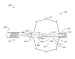
- FIG. 1is a perspective view of a containment device in accordance with the present invention
- FIG. 2is a side elevational view of the containment device shown in FIG. 1 ;
- FIG. 3is a perspective view of a containment device in accordance with an alternate embodiment of the present invention.
- FIG. 4is a side elevational view of the embodiment shown in FIG. 3 ;
- FIG. 5is a perspective view of a containment device in accordance with a further embodiment of the present invention.
- FIG. 6is a side elevational view of the embodiment of FIG. 5 ;
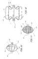
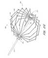
- FIG. 7is a perspective view of a support structure for a containment device in accordance with a further embodiment of the present invention.
- FIG. 7Ais a side elevational view of the device of FIG. 7 ;
- FIG. 7Bis an end view taken along the line 7 B- 7 B of FIG. 7A ;
- FIG. 8is a schematic illustration of an inflatable balloon positioned within the containment device of FIG. 7 ;
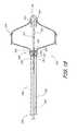
- FIG. 9is a schematic view of a pull string deployment embodiment of the containment device of FIG. 7 ;
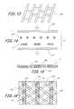
- FIGS. 10 and 11are side elevational schematic representations of partial and complete barrier layers on the containment device of FIG. 7 ;
- FIG. 12is a side elevational schematic view of an alternate containment device in accordance with another embodiment of the present invention.
- FIG. 13is a schematic view of a bonding layer mesh for use in forming a composite barrier membrane in accordance with an embodiment of the present invention
- FIG. 14is an exploded cross sectional view of the components of a composite barrier member in accordance with an embodiment of the present invention.
- FIG. 15is a cross sectional view through a composite barrier formed from the components illustrated in FIG. 14 ;
- FIG. 16is a top plan view of the composite barrier illustrated in FIG. 15 ;
- FIG. 17is a schematic view of a deployment system in accordance with one embodiment of the present invention.
- FIG. 17Ais an enlarged view of the deployment system of FIG. 17 , showing a releasable lock in an engaged configuration
- FIG. 17Bis an enlarged view as in FIG. 17A , with a core axially retracted to release the implant;
- FIG. 18is a perspective view of a flexible guide tube for use in the configurations of FIG. 17 and/or FIG. 19 ;
- FIG. 19is a schematic view of an alternate deployment system in accordance with one embodiment of the present invention.
- FIGS. 19A-19Billustrate a removal sequence for an implanted device in accordance with one embodiment of the present invention
- FIG. 20is a schematic cross sectional view through the distal end of a retrieval catheter having a containment device removably connected thereto;
- FIG. 20Ais a schematic cross sectional view of the system illustrated in FIG. 20 , with the containment device axially elongated and radially reduced;
- FIG. 20Bis a cross sectional schematic view as in FIG. 20A , with the containment device drawn part way into the delivery catheter;
- FIG. 20Cis a schematic view as in FIG. 20B , with the containment device and delivery catheter drawn into a transseptal sheath;
- FIG. 21is a schematic cross sectional view of a distal portion of an adjustable implant deployment system
- FIG. 21Ais a schematic cross sectional view of a slider assembly for use with the adjustable implant deployment system of FIG. 21 ;
- FIG. 21Bis a cross sectional view of the slider assembly of FIG. 21A taken along cut line 21 B- 21 B;
- FIG. 21Cis a perspective view of the slider assembly of FIG. 21 shown coupled to an axially moveable core;
- FIG. 21Dis a partial cut away view of the slider assembly of FIG. 21C showing the position of the axially moveable core with respect to the slider nut of the slider assembly;
- FIG. 21Eis a partial cut away view of the slider assembly of FIG. 21 shown coupled to the frame of a detachable implant;
- FIG. 22is a schematic cross sectional view of a distal portion of another embodiment of an adjustable implant deployment system
- FIG. 22Ais a schematic cross sectional view of a slider assembly for use with the adjustable implant deployment system of FIG. 22 ;
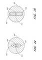
- FIG. 23is a schematic cross sectional view of another embodiment of a slider assembly
- FIGS. 24 and 25are alternative cross sectional views taken along cut line A-A of FIG. 23 ;
- FIG. 26is a schematic cross sectional view of another slider assembly for use with the adjustable implant deployment system of FIG. 21 ;
- FIG. 26Ais a schematic cross sectional view of another slider assembly for use with the adjustable implant deployment system of FIG. 21 ;
- FIG. 27is a cross sectional view taken along cut line 27 - 27 of FIG. 26 ;
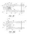
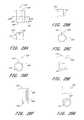
- FIG. 28is a schematic cross sectional view of a slider assembly incorporating quick-disconnect functionality
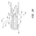
- FIG. 29is a schematic cross sectional view of another slider assembly incorporating quick-disconnect functionality, constructed in accordance with another embodiment of the present invention.
- FIG. 29Ais a side elevational view of a bayonet mount coupling the guide tube of the slider assembly of an implant to an axial moveable core, in accordance with one embodiment of the present invention
- FIG. 29Bis a side elevational view of the axially moveable core of FIG. 29A ;
- FIG. 29Cis an end view of the axially moveable core of FIG. 29A ;
- FIG. 29Dis an end view of the guide tube of the slider assembly of the implant of FIG. 29A ;
- FIG. 29Eis a side elevational view of one embodiment of a maze-type slotted guide tube in accordance with one embodiment of the present invention.
- FIG. 29Fis a side elevational view of another embodiment of a maze-type slotted guide tube in accordance with one embodiment of the present invention.
- FIG. 29Gis an end view of an axially moveable core in accodance with another embodiment of the present invention.
- FIG. 29His one embodiment of a key mount coupling a first and second portion of an axially moveable core in accordance with one embodiment of the present invention.
- FIG. 29Iis a schematic cross sectional view of the key mount of FIG. 29H taken along cut line 29 I- 29 I;
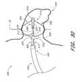
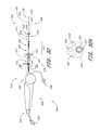
- FIG. 30is a schematic view of a deployment system delivering an implantable containment device to the left atrial appendage;
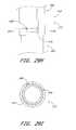
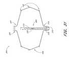
- FIG. 31is a schematic cross sectional view of an implantable containment device built in accordance with one embodiment of the present invention.
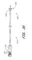
- FIG. 32is a schematic view of a delivery system constructed in accordance with one embodiment of the present invention.
- FIG. 32Ais a cross sectional view of a deployment catheter as shown in FIG. 32 , taken along cut line 32 A- 32 A.
- FIG. 33is a schematic view of the delivery system of FIG. 32 , shown attached to an implantable containment device;
- FIGS. 34A and 34Bare a schematic cross sectional view and an end view, respectively, of a loading collar used in the system of FIG. 32 ;
- FIG. 35is a schematic view of a recapture sheath used in the system of FIG. 32 ;
- FIG. 36is an enlarged partial cross sectional view of the deployment system of FIG. 32 ;
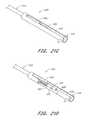
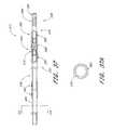
- FIG. 37is a partial cross sectional view of an axially moveable core used in the system of FIG. 32 ;
- FIG. 37Ais a cross sectional view of the axially moveable core of FIG. 37 taken along cut line 37 A- 37 A;
- FIGS. 38A-Care a schematic view of a transseptal sheath used in combination with the system of FIG. 32 .
- FIGS. 1 and 2there is illustrated one embodiment of an occlusion or containment device 10 in accordance with the present invention.
- the present inventionwill be described primarily in the context of an occlusion device, the present inventors also contemplate omitting the fabric cover or enlarging the pore size to produce implantable filters or other devices which are enlargeable at a remote implantation site.
- the terms “occlusion device” or “containment device”are intended to encompass all such devices.
- the occlusion device 10comprises an occluding member 11 comprising a frame 14 and a barrier 15 .
- the frame 14comprises a plurality of radially outwardly extending spokes 17 each having a length within the range of from about 0.5 cm to about 2 cm from a hub 16 .
- the spokeshave an axial length of about 1.5 cm.
- anywhere within the range of from about 3 spokes to about 40 spokesmay be utilized. In some embodiments, anywhere from about 12 to about 24 spokes are utilized, and, 18 spokes are utilized in one embodiment.
- the spokesare advanceable from a generally axially extending orientation such as to fit within a tubular introduction catheter to a radially inclined orientation as illustrated in FIG. 1 and FIG. 2 following deployment from the catheter.
- the spokesare biased radially outwardly such that the occlusion member expands to its enlarged, implantation cross-section under its own bias following deployment from the catheter.
- the occlusion membermay be enlarged using any of a variety of enlargement structures such as an inflatable balloon, or a catheter for axially shortening the occlusion member, as is discussed further below.
- the spokescomprise a metal such as stainless steel, nitinol, Elgiloy, or others which can be determined through routine experimentation by those of skill in the art.
- Wires having a circular or rectangular cross-sectionmay be utilized depending upon the manufacturing technique.
- rectangular cross section spokesare cut such as by known laser cutting techniques from tube stock, a portion of which forms the hub 16 .
- the barrier 15may comprise any of a variety of materials which facilitate cellular in-growth, such as ePTFE. The suitability of alternate materials for barrier 15 can be determined through routine experimentation by those of skill in the art.
- the barrier 15may be provided on either one or both axially facing sides of the occlusion member.
- the barrier 15comprises two layers, with one layer on each side of the frame 14 .
- the two layersmay be bonded to each other around the spokes 17 in any of a variety of ways, such as by heat bonding with or without an intermediate bonding layer such as polyethylene or FEP, adhesives, sutures, and other techniques which will be apparent to those of skill in the art in view of the disclosure herein.
- the barrier 15preferably has a thickness of no more than about 0.003′′ and a porosity within the range of from about 5 ⁇ m to about 60 ⁇ m.
- the barrier 15in one embodiment preferably is securely attached to the frame 14 and retains a sufficient porosity to facilitate cellular ingrowth and/or attachment.
- a bonding layer 254preferably comprises a mesh or other porous structure having an open surface area within the range of from about 10% to about 90%.
- the open surface area of the meshis within the range of from about 30% to about 60%.
- the opening or pore size of the bonding layer 254is preferably within the range of from about 0.005 inches to about 0.050 inches, and, in one embodiment, is about 0.020 inches.
- the thickness of the bonding layer 254can be varied widely, and is generally within the range of from about 0.0005 inches to about 0.005 inches. In a preferred embodiment, the bonding layer 254 has a thickness of about 0.001 to about 0.002 inches.
- One suitable polyethylene bonding meshis available from Smith and Nephew, under the code SN9.
- the bonding layer 254is preferably placed adjacent one or both sides of a spoke or other frame element 14 .
- the bonding layer 254 and frame 14 layersare then positioned in-between a first membrane 250 and a second membrane 252 to provide a composite membrane stack.
- the first membrane 250 and second membrane 252may comprise any of a variety of materials and thicknesses, depending upon the desired functional result.
- the membranehas a thickness within the range of from about 0.0005 inches to about 0.010 inches.
- the membranes 250 and 252each have a thickness on the order of from about 0.001 inches to about 0.002 inches, and comprise porous ePTFE, having a porosity within the range of from about 10 microns to about 100 microns.
- the composite stackis heated to a temperature of from about 200° F. to about 300° F., for about 1 minute to about 5 minutes under pressure to provide a finished composite membrane assembly with an embedded frame 14 as illustrated schematically in FIG. 15 .
- the final composite membranehas a thickness within the range of from about 0.001 inches to about 0.010 inches, and, preferably, is about 0.002 to about 0.003 inches in thickness.
- the thicknesses and process parameters of the foregoingmay be varied considerably, depending upon the materials of the bonding layer 254 the first layer 250 and the second layer 252 .
- the resulting finished composite membranehas a plurality of “unbonded” windows or areas 256 suitable for cellular attachment and/or ingrowth.
- the attachment areas 256are bounded by the frame 14 struts, and the cross-hatch or other wall pattern formed by the bonding layer 254 .
- a regular window 256 patternis produced in the bonding layer 254 .
- the foregoing procedureallows the bonding mesh to flow into the first and second membranes 250 and 252 and gives the composite membrane 15 greater strength (both tensile and tear strength) than the components without the bonding mesh.
- the compositeallows uniform bonding while maintaining porosity of the membrane 15 , to facilitate tissue attachment.
- By flowing the thermoplastic bonding layer into the pores of the outer mesh layers 250 and 252the composite flexibility is preserved and the overall composite layer thickness can be minimized.
- the occlusion device 10may be further provided with a bulking element or stabilizer 194 .
- the stabilizer 194may be spaced apart along an axis from the occluding member 11 .
- a distal end 190 and a proximal end 192are identified for reference.
- the designation proximal or distalis not intended to indicate any particular anatomical orientation or deployment orientation within the deployment catheter.
- the stabilizer 194is spaced distally apart from the occluding member 11 .
- the occluding member 11has an expanded diameter within the range of from about 1 cm to about 5 cm, and, in one embodiment, about 3 cm.
- the axial length of the occluding member 11 in an expanded, unstressed orientation from the distal end 192 to the hub 16is on the order of about 1 cm.
- the overall length of the occlusion device 10 from the distal end 192 to the proximal end 190is within the range of from about 1.5 cm to about 4 cm and, in one embodiment, about 2.5 cm.
- the axial length of the stabilizer 194 between distal hub 191 and proximal hub 16is within the range of from about 0.5 cm to about 2 cm, and, in one embodiment, about 1 cm.
- the expanded diameter of the stabilizer 194is within the range of from about 0.5 cm to about 2.5 cm, and, in one embodiment, about 1.4 cm.
- the outside diameter of the distal hub 191 and proximal hub 16is about 2.5 mm.
- the occlusion device 10is provided with one or more retention structures for retaining the device in the left atrial appendage or other body cavity or lumen.
- a plurality of barbs or other anchors 195are provided, for engaging adjacent tissue to retain the occlusion device 10 in its implanted position and to limit relative movement between the tissue and the occlusion device.
- the illustrated anchorsare provided on one or more of the spokes 17 , or other portion of frame 14 .
- every spoke, every second spoke or every third spokeare provided with one or two or more anchors each.
- the illustrated anchoris in the form of a barb, with one on each spoke for extending into tissue at or near the opening of the LAA.
- two or three barbsmay alternatively be desired on each spoke.
- each barbis inclined in a proximal direction. This is to inhibit proximal migration of the implant out of the left atrial appendage.
- distalrefers to the direction into the left atrial appendage
- proximalrefers to the direction from the left atrial appendage into the heart.
- one or more barbsmay face distally, to inhibit distal migration of the occlusion device deeper into the LAA.
- the implantmay be provided with at least one proximally facing barb and at least one distally facing barb.
- a proximal plurality of barbsmay be inclined in a first direction
- a distal plurality of barbsmay be inclined in a second direction, to anchor the implant against both proximal and distal migration.
- anchors 195may also be provided on the stabilizer 194 , such that it assists not only in orienting the occlusion device 10 and resisting compression of the LAA, but also in retaining the occlusion device 10 within the LAA.
- Any of a wide variety of structuresmay be utilized for anchor 195 , either on the occluding member 11 or the stabilizer 194 or both, such as hooks, barbs, pins, sutures, adhesives, ingrowth surfaces and others which will be apparent to those of skill in the art in view of the disclosure herein.
- the occlusion device 10is preferably positioned within a tubular anatomical structure to be occluded such as the left atrial appendage.
- the occluding member 11is positioned across or near the opening to the LAA and the stabilizer 194 is positioned within the LAA.
- the stabilizer 194assists in the proper location and orientation of the occluding member 11 , as well as resists compression of the LAA behind the occluding member 11 .
- the present inventorshave determined that following deployment of an occluding member 111 without a stabilizer 194 or other bulking structure to resist compression of the LAA, normal operation of the heart may cause compression and resulting volume changes in the LAA, thereby forcing fluid past the occluding member 11 and inhibiting or preventing a complete seal. Provision of a stabilizer 194 dimensioned to prevent the collapse or pumping of the LAA thus minimizes leakage, and provision of the barbs facilitates endothelialization or other cell growth across the occluding member 11 .
- the stabilizer 194is preferably movable between a reduced cross-sectional profile for transluminal advancement into the left atrial appendage, and an enlarged cross-sectional orientation as illustrated to fill or to substantially fill a cross-section through the LAA.
- the stabilizing membermay enlarge to a greater cross section than the (pre-stretched) anatomical cavity, to ensure a tight fit and minimize the likelihood of compression.
- One convenient constructionincludes a plurality of elements 196 which are radially outwardly expandable in response to axial compression of a distal hub 191 towards a proximal hub 16 .
- Elements 196each comprise a distal segment 198 and a proximal segment 202 connected by a bend 200 .
- the elements 196may be provided with a bias in the direction of the radially enlarged orientation as illustrated in FIG. 2 , or may be radially expanded by applying an expansion force such as an axially compressive force between distal hub 191 and proximal hub 16 or a radial expansion force such as might be applied by an inflatable balloon.
- Elements 196may conveniently be formed by laser cutting the same tube stock as utilized to construct the distal hub 191 , proximal hub 16 and frame 14 , as will be apparent to those of skill in the art in view of the disclosure herein.
- the various components of the occlusion device 10may be separately fabricated or fabricated in subassemblies and secured together during manufacturing.
- a radiopaque dye or other visualizeable mediamay be introduced on one side or the other of the occlusion device, to permit visualization of any escaped blood or other fluid past the occlusion device.
- the occlusion devicemay be provided with a central lumen or other capillary tube or aperture which permits introduction of a visualizeable dye from the deployment catheter through the occlusion device and into the entrapped space on the distal side of the occlusion device.
- dyemay be introduced into the entrapped space distal to the occlusion device such as by advancing a small gauge needle from the deployment catheter through the barrier 15 on the occlusion device, to introduce dye.
- the occlusion device 10comprises an occlusion member 11 and a stabilizing member 194 as previously discussed.
- each of the distal segments 198inclines radially outwardly in the proximal direction and terminates in a proximal end 204 .
- the proximal end 204may be provided with an atraumatic configuration, for pressing against, but not penetrating, the wall of the left atrial appendage or other tubular body structure.
- Three or more distal segments 198are preferably provided, and generally anywhere within the range of from about 6 to about 20 distal segments 198 may be used. In one embodiment, 9 distal segments 198 are provided.
- three of the distal segments 198have an axial length of about 5 mm, and 6 of the distal segments 198 have an axial length of about 1 cm. Staggering the lengths of the distal segments 198 may axially elongate the zone in the left atrial appendage against which the proximal ends 204 provide anchoring support for the occlusion device.
- the occlusion device 10 illustrated in FIGS. 3 and 4is additionally provided with a hinge 206 to allow the longitudinal axis of the occlusion member 11 to be angularly oriented with respect to the longitudinal axis of the stabilizing member 194 .
- the hinge 206is a helical coil, although any of a variety of hinge structures can be utilized.
- the illustrated embodimentmay be conveniently formed by laser cutting a helical slot through a section of the tube from which the principal structural components of the occlusion device 10 are formed.
- an annular band 208connects the hinge 206 to a plurality of axially extending struts 210 .
- Axial struts 210are provided, spaced equilaterally around the circumference of the body.
- Axial struts 210may be formed from a portion of the wall of the original tube stock, which portion is left in its original axial orientation following formation of the distal segments 198 such as by laser cutting from the tubular wall.
- the occlusion member 11is provided with a proximal zone 212 on each of the spokes 17 .
- Proximal zone 212has an enhanced degree of flexibility, to accommodate the fit between the occlusion member 11 and the wall of the left atrial appendage.
- Proximal section 212may be formed by reducing the cross sectional area of each of the spokes 17 , which may be provided with a wave pattern as illustrated.
- Proximal point 214may be contained within layers of the barrier 15 , or may extend through or beyond the barrier 15 such as to engage adjacent tissue and assist in retaining the occlusion device 10 at the deployment site.
- the occlusion device 10is provided with a proximal face 216 on the occlusion member 11 , instead of the open and proximally concave face on the embodiment of FIGS. 1 and 2 .
- the proximal face 216is formed by providing a proximal spoke 218 which connects at an apex 220 to some or all of the distal spokes 17 .
- the proximal spoke 218 , and corresponding apex 220 and distal spoke 17may be an integral structure, such as a single ribbon or wire, or element cut from a tube stock as has been discussed.
- Proximal spokes 218are each attached to a hub 222 at the proximal end 192 of the occlusion device 10 .
- the barrier 15may surround either the proximal face or the distal face or both on the occlusion member 11 .
- provision of a proximal spoke 218 connected by an apex 220 to a distal spoke 17provides a greater radial force than a distal spoke 17 alone, which will provide an increased resistance to compression if the occlusion member 11 is positioned with the LAA.
- the occlusion device 10comprises an occluding member but does not include a distinct stabilizing member as has been illustrated in connection with previous embodiments. Any of the embodiments previously disclosed herein may also be constructed using the occluding member only, and omitting the stabilizing member as will be apparent to those of skill in the art in view of the disclosure herein.
- the occluding device 10comprises a proximal end 192 , a distal end 190 , and a longitudinal axis extending therebetween.
- a plurality of supports 228extend between a proximal hub 222 and a distal hub 191 . At least two or three supports 228 are provided, and preferably at least about ten. In one embodiment, sixteen supports 228 are provided. However, the precise number of supports 228 can be modified, depending upon the desired physical properties of the occlusion device 10 as will be apparent to those of skill in the art in view of the disclosure herein, without departing from the present invention.
- Each support 228comprises a proximal spoke portion 218 , a distal spoke portion 17 , and an apex 220 as has been discussed.
- Each of the proximal spoke portion 218 , distal spoke portion 17 and apex 220may be a region on an integral support 228 , such as a continuous rib or frame member which extends in a generally curved configuration as illustrated with a concavity facing towards the longitudinal axis of the occlusion device 10 .
- no distinct point or hinge at apex 220is necessarily provided.
- each support 228is provided with one or two or more barbs 195 .
- the occlusion device 10is in its enlarged orientation, such as for occluding a left atrial appendage or other body cavity or lumen.
- each of the barbs 195projects generally radially outwardly from the longitudinal axis, and is inclined in the proximal direction.
- One or more barbsmay also be inclined distally, as is discussed elsewhere herein.
- the barbs 195 and corresponding support 228are cut from a single ribbon, sheet or tube stock, the barb 195 will incline radially outwardly at approximately a tangent to the curve formed by the support 228 .
- the occlusion device 10 constructed from the frame illustrated in FIG. 7may be constructed in any of a variety of ways, as will become apparent to those of skill in the art in view of the disclosure herein.
- the occlusion device 10is constructed by laser cutting a piece of tube stock to provide a plurality of axially extending slots in-between adjacent supports 228 .
- each barb 195can be laser cut from the corresponding support 228 or space in-between adjacent supports 228 .
- the generally axially extending slots which separate adjacent supports 228end a sufficient distance from each of the proximal end 192 and distal end 190 to leave a proximal hub 222 and a distal hub 191 to which each of the supports 228 will attach.
- an integral cage structuremay be formed.
- each of the components of the cage structuremay be separately formed and attached together such as through soldering, brazing, heat bonding, adhesives, and other fastening techniques which are known in the art.
- a further method of manufacturing the occlusion device 10is to laser cut a slot pattern on a flat sheet of appropriate material, such as a flexible metal or polymer, as has been discussed in connection with previous embodiments. The flat sheet may thereafter be rolled about an axis and opposing edges bonded together to form a tubular structure.
- the apex portion 220 which carries the barb 195may be advanced from a low profile orientation in which each of the supports 228 extend generally parallel to the longitudinal axis, to an implanted orientation as illustrated, in which the apex 220 and the barb 195 are positioned radially outwardly from the longitudinal axis.
- the support 228may be biased towards the enlarged orientation, or may be advanced to the enlarged orientation under positive force following positioning within the tubular anatomical structure, in any of a variety of manners.
- an inflatable balloon 230is positioned within the occlusion device 10 .
- Inflatable balloon 230is connected by way of a removable coupling 232 to an inflation catheter 234 .
- Inflation catheter 234is provided with an inflation lumen for providing communication between an inflation media source 236 outside of the patient and the balloon 230 .
- the balloon 230is inflated, thereby engaging barbs 195 with the surrounding tissue.
- the inflation catheter 234is thereafter removed, by decoupling the removable coupling 232 , and the inflation catheter 234 is thereafter removed.
- the balloon 230may be either left in place within the occlusion device 10 , or deflated and removed by the inflation catheter 234 .
- the supports 228are radially enlarged such as through the use of a deployment catheter 238 .
- Deployment catheter 238comprises a lumen for movably receiving a deployment element such as a flexible line 240 .
- Deployment line 240extends in a loop 244 formed by an aperture or slip knot 242 .
- proximal retraction on the deployment line 240 while resisting proximal movement of proximal hub 222such as by using the distal end of the catheter 238 will cause the distal hub 191 to be drawn towards the proximal hub 222 , thereby radially enlarging the cross-sectional area of the occlusion device 10 .
- the supports 228will retain the radially enlarged orientation by elastic deformation, or may be retained in the enlarged orientation such as by securing the slip knot 242 immovably to the deployment line 240 at the fully radially enlarged orientation. This may be accomplished in any of a variety of ways, using additional knots, clips, adhesives, or other techniques known in the art.
- a pull wire 240may be removably attached to the distal hub 191 or other distal point of attachment on the occlusion device 10 . Proximal retraction of the pull wire 240 while resisting proximal motion of the proximal hub 222 such as by using the distal end of the catheter 238 will cause enlargement of the occlusion device 10 as has been discussed.
- the pull wire 240may then be locked with respect to the proximal hub 222 and severed or otherwise detached to enable removal of the deployment catheter 238 and proximal extension of the pull wire 240 . Locking of the pull wire with respect to the proximal hub 222 may be accomplished in any of a variety of ways, such as by using interference fit or friction fit structures, adhesives, a knot or other technique depending upon the desired catheter design.
- the occlusion device 10may be provided with a barrier 15 such as a mesh or fabric as has been previously discussed.
- Barrier 15may be provided on only one hemisphere such as proximal face 216 , or may be carried by the entire occlusion device 10 from proximal end 192 to distal end 190 .
- the barriermay be secured to the radially inwardly facing surface of the supports 228 , as illustrated in FIG. 11 , or may be provided on the radially outwardly facing surfaces of supports 228 , or both.
- FIG. 12A further embodiment of the occlusion device 10 is illustrated in FIG. 12 , in which the apex 220 is elongated in an axial direction to provide additional contact area between the occlusion device 10 and the wall of the tubular structure.
- one or two or three or more anchors 195may be provided on each support 228 , depending upon the desired clinical performance.
- the occlusion device 10 illustrated in FIG. 12may also be provided with any of a variety of other features discussed herein, such as a partial or complete barrier 15 .
- the occlusion device 10 illustrated in FIG. 12may be enlarged using any of the techniques disclosed elsewhere herein.
- An adjustable implant deployment system 300comprises generally a catheter 302 for placing a detachable implant 304 within a body cavity or lumen, as has been discussed.
- the catheter 302comprises an elongate flexible tubular body 306 , extending between a proximal end 308 and a distal end 310 .
- the catheteris shown in highly schematic form, for the purpose of illustrating the functional aspects thereof.
- the catheter bodywill have a sufficient length and diameter to permit percutaneous entry into the vascular system, and transluminal advancement through the vascular system to the desired deployment site.
- the catheter 302will have a length within the range of from about 50 cm to about 150 cm, and a diameter of generally no more than about 15 French. Further dimensions and physical characteristics of catheters for navigation to particular sites within the body are well understood in the art and will not be further described herein.
- the tubular body 306is further provided with a handle 309 generally on the proximal end 308 of the catheter 302 .
- the handle 309permits manipulation of the various aspects of the implant deployment system 300 , as will be discussed below.
- Handle 309may be manufactured in any of a variety of ways, typically by injection molding or otherwise forming a handpiece for single-hand operation, using materials and construction techniques well known in the medical device arts.
- the implant 304may be in the form of any of those described previously herein, as modified below.
- the implantis movable from a reduced crossing profile to an enlarged crossing profile, such that it may be positioned within a body structure and advanced from its reduced to its enlarged crossing profile to obstruct blood flow or perform other functions while anchored therein.
- the implant 304may be biased in the direction of the enlarged crossing profile, may be neutrally biased or may be biased in the direction of the reduced crossing profile. Any modifications to the device and deployment system to accommodate these various aspects of the implant 304 may be readily accomplished by those of skill in the art in view of the disclosure herein.
- the distal end 314 of the implant 304is provided with an implant plug 316 .
- Implant plug 316provides a stopping surface 317 for contacting an axially movable core 312 .
- the core 312extends axially throughout the length of the catheter body 302 , and is attached at its proximal end to a core control 332 on the handle 309 .
- the core 312may comprise any of a variety of structures which has sufficient lateral flexibility to permit navigation of the vascular system, and sufficient axial column strength to enable reduction of the implant 304 to its reduced crossing profile. Any of a variety of structures such as hypotube, solid core wire, “bottomed out” coil spring structures, or combinations thereof may be used, depending upon the desired performance of the finished device.
- the core 312comprises stainless steel tubing.
- the distal end of core 312is positioned within a recess or lumen 322 defined by a proximally extending guide tube 320 .
- the guide tube 320is a section of tubing such as metal hypotube, which is attached at the distal end 314 of the implant and extends proximally within the implant 304 .
- the guide tube 320preferably extends a sufficient distance in the proximal direction to inhibit buckling or prolapse of the core 312 when distal pressure is applied to the core control 332 to reduce the profile of the implant 304 .
- the guide tube 320should not extend proximally a sufficient distance to interfere with the opening of the implant 304 .
- the guide tube 320may operate as a limit on distal axial advancement of the proximal end 324 of implant 304 .
- the guide tube 320preferably does not extend sufficiently far proximally from the distal end 314 to interfere with optimal opening of the implant 304 .
- the specific dimensionsare therefore relative, and will be optimized to suit a particular intended application.
- the implant 304has an implanted outside diameter within the range of from about 5 mm to about 45 mm, and an axial implanted length within the range of from about 5 mm to about 45 mm.
- the guide tube 320has an overall length of about 3 mm to about 35 mm, and an outside diameter of about 0.095 inches.
- FIG. 18An alternate guide tube 320 is schematically illustrated in FIG. 18 .
- the guide tube 320comprises a plurality of tubular segments 321 spaced apart by an intervening space 323 .
- Thisallows increased flexibility of the guide tube 320 , which may be desirable during the implantation step, while retaining the ability of the guide tube 320 to maintain linearity of the core 312 while under axial pressure.
- three segments 321are illustrated in FIG. 18 , as many as 10 or 20 or more segments 321 may be desirable depending upon the desired flexibility of the resulting implant.
- each adjacent pair of segments 321may be joined by a hinge element 325 which permits lateral flexibility.
- the hinge element 325comprises an axially extending strip or spine, which provides column strength along a first side of the guide tube 320 .
- the guide tube 320may therefore be curved by compressing a second side of the guide tube 320 which is generally offset from the spine 325 by about 180°.
- a limit on the amount of curvaturemay be set by adjusting the axial length of the space 323 between adjacent segments 321 .
- each axial spine 325may be rotationally offset from the next adjacent axial spine 325 to enable flexibility of the overall guide tube 320 throughout a 360° angular range of motion.
- each adjacent segment 321may be provided by cutting a spiral groove or plurality of parallel grooves in a tubular element in between what will then become each adjacent pair of segments 321 .
- each tubular element 321will be separated by an integral spring like structure, which can permit flexibility.
- the entire length of the guide tube 320may comprise a spring.
- Each of the forgoing embodimentsmay be readily constructed by laser cutting or other cutting from a piece of tube stock, to produce a one piece guide tube 320 .
- the guide tube 320may be assembled from separate components and fabricated together using any of a variety of bonding techniques which are appropriate for the construction material selected for the tube 320 .
- the distal implant plug 316extends within the implant 304 and is attached to the distal end of the guide tube 320 .
- the implant plug 316may be secured to the guide tube 320 and implant 304 in any of a variety of ways, depending upon the various construction materials. For example, any of a variety of metal bonding techniques such as a welding, brazing, interference fit such as threaded fit or snap fit, may be utilized. Alternatively, any of a variety of bonding techniques for dissimilar materials may be utilized, such as adhesives, and various molding techniques.
- the implant plug 316comprises a molded polyethylene cap, and is held in place utilizing a distal cross pin 318 which extends through the implant 304 , the guide tube 320 and the implant plug 316 to provide a secure fit against axial displacement.
- the proximal end 324 of the implant 304is provided with a releasable lock 326 for attachment to a release element such as pull wire 328 .
- Pull wire 328extends proximally throughout the length of the tubular body 306 to a proximal pull wire control 330 on the handle 309 .
- the term pull wireis intended to include any of a wide variety of structures which are capable of transmitting axial tension or compression such as a pushing or pulling force with or without rotation from the proximal end 308 to the distal end 310 of the catheter 302 .
- monofilament or multifilament metal or polymeric rods or wires, woven or braided structuresmay be utilized.
- tubular elementssuch as a concentric tube positioned within the outer tubular body 306 may also be used as will be apparent to those of skill in the art.
- the pull wire 328is releasably connected to the proximal end 324 of the implant 304 .
- Thispermits proximal advancement of the proximal end of the implant 304 , which cooperates with a distal retention force provided by the core 312 against the distal end of the implant to axially elongate the implant 304 thereby reducing it from its implanted configuration to its reduced profile for implantation.
- the proximal end of the pull wire 328may be connected to any of a variety of pull wire controls 330 , including rotational knobs, levers and slider switches, depending upon the design preference.
- the proximal end 324 of the implant 304is thus preferably provided with a releasable lock 326 for attachment of the pull wire 328 to the deployment catheter.
- the releasable lockis formed by advancing the pull wire distally around a cross pin 329 , and providing an eye or loop which extends around the core 312 . As long as the core 312 is in position within the implant 304 , proximal retraction of the pull wire 328 will advance the proximal end 324 of the implant 304 in a proximal direction. See FIG. 17A .
- proximal retraction of the core 312such as by manipulation of the core control 332 will pull the distal end of the core 312 through the loop on the distal end of the pull wire 328 .
- the pull wire 328may then be freely proximally removed from the implant 304 , thereby enabling detachment of the implant 304 from the deployment system 300 within a treatment site. See FIG. 17B .
- the implant deployment system 300thus permits the implant 304 to be maintained in a low crossing profile configuration, to enable transluminal navigation to a deployment site. Following positioning at or about the desired deployment site, proximal retraction of the core 312 enables the implant 304 to radially enlarge under its own bias to fit the surrounding tissue structure. Alternatively, the implant can be enlarged under positive force, such as by inflation of a balloon or by a mechanical mechanism as is discussed elsewhere herein. Once the clinician is satisfied with the position of the implant 304 , such as by injection of dye and visualization using conventional techniques, the core 312 is proximally retracted thereby releasing the lock 326 and enabling detachment of the implant 304 from the deployment system 300 .
- the present inventionpermits the implant 304 to be enlarged or reduced by the clinician to permit repositioning and/or removal of the implant 304 as may be desired.
- the implantmay be radially enlarged or reduced by rotating a torque element extending throughout the deployment catheter.
- the elongate flexible tubular body 306 of the deployment catheter 302includes a rotatable torque rod 340 extending axially therethrough.
- the proximal end of the torque rod 340may be connected at a proximal manifold to a manual rotation device such as a hand crank, thumb wheel, rotatable knob or the like.
- the torque rod 340may be connected to a power driven source of rotational energy such as a motor drive or air turbine.
- the distal end of the torque rod 340is integral with or is connected to a rotatable core 342 which extends axially through the implant 304 .
- a distal end 344 of the rotatable core 342is positioned within a cavity 322 as has been discussed.
- torque rod or torque elementare intended to include any of a wide variety of structures which are capable of transmitting a rotational torque throughout the length of a catheter body.
- solid core elementssuch as stainless steel, nitinol or other nickel titanium alloys, or polymeric materials may be utilized.
- the torque rod 340is preferably provided with an axially extending central guidewire lumen. This may be accomplished by constructing the torque rod 340 from a section of hypodermic needle tubing, having an inside diameter of from about 0.001 inches to about 0.005 inches or more greater than the outside diameter of the intended guidewire.
- Tubular torque rods 340may also be fabricated or constructed utilizing any of a wide variety of polymeric constructions which include woven or braided reinforcing layers in the wall. Torque transmitting tubes and their methods of construction are well understood in the intracranial access and rotational atherectomy catheter arts, among others, and are not described in greater detail herein. Use of a tubular torque rod 340 also provides a convenient infusion lumen for injection of contrast media within the implant 304 , such as through a port 343 .
- the proximal end 324 of the implant 304is provided with a threaded aperture 346 through which the core 342 is threadably engaged.
- rotation of the threaded core 342 in a first direction relative to the proximal end 324 of the implant 304will cause the rotatable core 342 to advance distally. This distal advancement will result in an axial elongation and radial reduction of the implantable device 304 .
- Rotation of the rotatable core 342 in a reverse directionwill cause a proximal retraction of the rotatable core 342 , thus enabling a radial enlargement and axial shortening of the implantable device 304 .
- the deployment catheter 302is further provided with an antirotation lock 348 between a distal end 350 of the tubular body 306 and the proximal end 324 of the implant 304 .
- the rotational lock 348may be conveniently provided by cooperation between a first surface 352 on the distal end 350 of the deployment catheter 302 , which engages a second surface 354 on the proximal end 324 of the implantable device 304 , to rotationally link the deployment catheter 302 and the implantable device 304 .
- Any of a variety of complementary surface structuresmay be provided, such as an axial extension on one of the first and second surfaces for coupling with a corresponding recess on the other of the first and second surfaces.
- Such extensions and recessesmay be positioned laterally offset from the axis of the catheter. Alternatively, they may be provided on the longitudinal axis with any of a variety of axially releasable anti-rotational couplings having at least one flat such as a hexagonal or other multifaceted cross sectional configuration.
- one or more projections 356 on the first surface 352may engage a corresponding recess 358 on the second surface 354 .
- Any of a variety of alternative complementary surface structuresmay also be provided, as will be apparent to those of skill in the art in view of the disclosure herein.
- the projection 356is in the form of an axially extending pin for engaging a complimentary recess 358 on the proximal end 324 of the implant 304 .
- FIG. 19Billustrates an axially extending spline 356 for receipt within a complimentary axially extending recess 358 .
- the various pin, spline and other structuresmay be reversed between the distal end of tubular body 306 and the proximal end 324 of the implant 304 as will be apparent to those of skill in the art in view of the disclosure herein.
- the torque rod 340Upon placement of the implantable device 304 at the desired implantation site, the torque rod 340 is rotated in a direction that produces an axial proximal retraction. This allows radial enlargement of the radially outwardly biased implantable device 304 at the implantation site. Continued rotation of the torque rod 340 will cause the threaded core 342 to exit proximally through the threaded aperture 346 . At that point, the deployment catheter 302 may be proximally retracted from the patient, leaving the implanted device 304 in place.
- the rotatable core 342may be left within the implantable device 304 , as may be desired depending upon the intended deployment mechanism.
- the distal end of the core 342may be rotatably locked within the end cap 326 , such as by including complimentary radially outwardly or inwardly extending flanges and grooves on the distal end of the core 342 and inside surface of the cavity 322 .
- proximal retraction of the core 342 by rotation thereof relative to the implantable device 304will pull the end cap 326 in a proximal direction under positive force. This may be desirable as a supplement to or instead of a radially enlarging bias built into the implantable device 304 .
- the distal end of the tubular body 306may be provided with a zone or point of enhanced lateral flexibility. This may be desirable in order allow the implant to seat in the optimal orientation within the left atrial appendage, and not be restrained by a lack of flexibility in the tubular body 306 . This may be accomplished in any of a variety of ways, such as providing the distal most one or two or three centimeters or more of the tubular body 306 with a spring coil configuration. In this manner, the distal end of the tubular body 306 will be sufficiently flexible to allow the implant 304 to properly seat within the LAA.
- This distal flex zone on the tubular body 306may be provided in any of a variety of ways, such as by cutting a spiral slot in the distal end of the tubular body 306 using laser cutting or other cutting techniques.
- the components within the tubular body 306such as torque rod 340 may similarly be provided with a zone of enhanced flexibility in the distal region of the tubular body 306 .
- the implantable device 304may also be retrieved and removed from the body in accordance with a further aspect of the present invention.
- One manner of retrieval and removalwill be understood in connection with FIGS. 20 through 20C .
- a previously implanted device 304is illustrated as releasably coupled to the distal end of the tubular body 306 , as has been previously discussed. Coupling may be accomplished by aligning the tubular body 306 with the proximal end 324 of the deployed implant 304 , under fluoroscopic visualization, and distally advancing a rotatable core 342 through the threaded aperture 346 . Threadable engagement between the rotatable core 342 and aperture 346 may thereafter be achieved, and distal advancement of core 342 will axially elongate and radially reduce the implant 304 .
- the tubular body 306is axially movably positioned within an outer tubular delivery or retrieval catheter 360 .
- Catheter 360extends from a proximal end (not illustrated) to a distal end 362 .
- the distal end 362is preferably provided with a flared opening, such as by constructing a plurality of petals 364 for facilitating proximal retraction of the implant 304 as will become apparent.
- Petals 364may be constructed in a variety of ways, such as by providing axially extending slits in the distal end 362 of the delivery catheter 360 . In this manner, preferably at least about three, and generally at least about four or five or six petals or more will be provided on the distal end 362 of the delivery catheter 360 . Petals 364 manufactured in this manner would reside in a first plane, transverse to the longitudinal axis of the delivery catheter 360 , if each of such petals 364 were inclined at 90 degrees to the longitudinal axis of the delivery catheter 360 .
- a second layer of petals 365are provided, which would lie in a second, adjacent plane if the petals 365 were inclined at 90 degrees to the longitudinal axis of the delivery catheter 360 .
- the second plane of petals 365is rotationally offset from the first plane of petals 364 , such that the second petals 365 cover the spaces 367 formed between each adjacent pair of petals 365 .
- the use of two or more layers of staggered petals 364 and 365has been found to be useful in retrieving implants 304 , particularly when the implant 304 carries a plurality of tissue anchors 195 .
- the petals 364 and 365may be manufactured from any of a variety of polymer materials useful in constructing medical device components such as the delivery catheter 360 . This includes, for example, polyethylene, PET, PEEK, PEBAX, and others well known in the art.
- the second petals 365may be constructed in any of a variety of ways. In one convenient construction, a section of tubing which concentrically fits over the delivery catheter 360 is provided with a plurality of axially extending slots in the same manner as discussed above. The tubing with a slotted distal end may be concentrically positioned on the catheter 360 , and rotated such that the space between adjacent petals 365 is offset from the space between adjacent petals 364 .
- the hub of the petals 365may thereafter be bonded to the catheter 360 , such as by heat shrinking, adhesives, or other bonding techniques known in the art.
- the radially reduced implant 304is proximally retracted part way into the delivery catheter 360 . This can be accomplished by proximally retracting the tubular body 306 and/or distally advancing the catheter 360 . As illustrated in FIG. 20 b , the tubular body 306 having the implant 304 attached thereto is proximally retracted a sufficient distance to position the tissue anchors 195 within the petals 364 . The entire assembly of the tubular body 306 , within the delivery catheter 360 may then be proximally retracted within the transseptal sheath 366 or other tubular body as illustrated in FIG. 20 c .
- the collapsed petals 364allow this to occur while preventing engagement of the tissue anchors 195 with the distal end of the transseptal sheath 366 or body tissue.
- the entire assembly having the implantable device 304 contained thereinmay thereafter be proximally withdrawn from or repositioned within the patient.
- Adjustable implant deployment system 300comprises catheter 302 and detachable implant 304 having a frame 506 and anchors or barbs 195 , as discussed in greater detail above with respect to FIG. 17 and other figures.
- the deployment system 300also includes a slider assembly 400 .
- slider assembly 400includes a guide tube 320 extending proximally from the distal end or distal hub 314 of the implant, and a slider nut 402 slidably received in a channel 430 of the guide tube 320 .
- Slider nut 402preferably includes a flange 404 operable to travel within a longitudinal slot 410 that extends at least partially along the length of guide tube 320 .
- the flange 404 of the slider nut 402has a proximal surface 406 and a distal surface 408 .
- Slot 410has a proximal surface 412 , and in one embodiment, extends through the distal end of the guide tube 320 .
- Slot 410may have a generally rectangular shape.
- proximal movement of the flange 404 within the slot 410is limited by interference between the proximal surfaces 406 , 412 , of flange 404 and guide tube 320 , respectively, as slider nut 402 is moved in the proximal direction.
- distal movement of the flange 404 within the slot 410is limited by interference between the axially moveable core 312 and the cross pin 318 , as described in greater detail with reference to FIG. 21A below.
- flange 404prevents slider nut 402 from rotating within guide tube 320 due to the interference between flange 404 and the side walls of the slot 410 .
- the slot 410 of the guide tube 320is laser-cut, and has a length in the range between about 3 mm and 35 mm, and a width in the range between about 0.5 mm and 2 mm. In one embodiment, the length of the guide tube 320 slot 410 is in the range between about 0.4 in and about 0.826 in. In one embodiment, the width of the guide tube 320 slot 410 is in the range between about 0.02 in and about 0.04 in.
- the slider nut 402is a keyed polymer extrusion, and is sized so that it fits and slides at least partially within the guide tube 320 . Such material is advantageous in that it provides a reduced friction interface between the slider nut 402 and the guide tube 320 .
- the slider nut 402is made from plastic, metal, or ceramic. In another embodiment, the slider nut 402 is made from PEBAX, polyethylene, polyurethane, nickel titanium, or stainless steel. Flange 404 may be integrally formed with the slider nut 402 , or may be attached to it. In one embodiment, flange 404 is made from plastic, and is sized so that it fits and slides within the slot 410 of the guide tube 320 . The exact length of the flange 404 is selected based upon the dimensions of the slot 410 , and will vary based upon the clinical parameters of the particular treatment.
- FIGS. 21A-21ESeveral views of one embodiment of the adjustable implant deployment system 300 of FIG. 21 are shown in FIGS. 21A-21E .
- FIG. 21Aillustrates the distal end 344 of an axially moveable core 312 similar to that described above, releasably coupled to a slider assembly 400 .
- Slider assembly 400includes guide tube 320 and slider nut 402 , as described above.
- Slider nut 402includes a flange 404 as described above and a mating surface 420 for receiving the distal end 344 of axially moveable core 312 .
- mating surface 420 of nut 402is an internally threaded surface.
- Mating surface 420 of nut 402engages mating surface 422 of axially moveable core 312 to provide axial coupling between the movement of the axially moveable core 312 and the slider nut 402 .
- mating surface 422 of axially moveable core 312is an externally threaded surface on a distal section of the axially moveable core which terminates proximal to the very distal tip of the axially moveable core 312 .
- the axially moveable core 312includes a proximal shaft 576 , a flexible core section 564 , and a distal shaft 578 as described in greater detail below with reference to FIG. 37 .
- the distal shaft 578includes a mating surface 584 (as shown on FIG. 37 ), which corresponds to the mating surface 422 of the axially moveable core 312 as shown on FIG. 21A .
- the mating surface 422 of axially moveable core 312preferably is a threaded surface to facilitate releasable attachment to the mating surface 420 of the slider nut 402 .
- the mating surface 422provides self-tapping functionality to the axially moveable core 312 .
- the mating surface 422 of the axially moveable core 312includes threads, and is self-tapping as it is inserted into the slider nut 402 of the slider assembly 400 .
- the slider nut 402contains a central lumen extending axially therethrough.
- the mating surface 420 of the slider nut 402does not contain threads, but is tapped (e.g., mating threads are created), as the axially moveable core 312 is inserted into, and rotated with respect to the slider nut 402 .
- the axially moveable core 312preferably is attached to the slider nut 402 by rotating the axially moveable core 312 such that the threads of the mating surface 422 of axially moveable core 312 engage threads of the mating surface 420 of nut 402 .
- axially moveable core 312is detached or decoupled from the slider nut 402 of the slider assembly 400 by rotating the axially moveable core 312 in the opposite direction.
- the threads of the mating surface 422 of axially moveable core 312disengage the threads of the mating surface 420 of nut 402 , thereby releasing the axially moveable core 312 from the slider nut 402 , slider assembly 400 , and implant 304 . Additional description of the axially moveable core 312 and contemplated alternative embodiments are provided below, including the illustration and discussion related to FIG. 37 .
- the axially moveable core 312releasably coupled to the slider nut 402 of the slider assembly 400 of an implant 304 .
- the mating surface 422 of axially moveable core 312is coupled with the mating surface 420 of nut 402 such that the distal end surface 429 of the axially moveable core 312 and a marker 431 reside distal the slider nut 402 of the slider assembly 400 .
- the axially moveable core 312is coupled to the slider nut 402 such that the marker 431 resides approximately 1 to 3 mm distal the distal surface 418 of slider nut 402 .
- the axially moveable core 312is coupled to the slider nut 402 of the slider assembly 400 such that the distal surface 429 of the axially moveable core 312 and/or the marker 431 reside within slider nut 402 . Examples of such embodiments are provided in greater detail below with reference to FIGS. 22A , 23 , and 26 .
- axially moveable core 312also includes a lumen 426 .
- the lumen 426preferably allows visualization dye to flow through the lumen 426 of the axially moveable core 312 , through the lumen 428 of the implant plug 316 , and into the left atrial appendage.
- visualization dyeis useful for clinical diagnosis and testing of the position of the implant 304 within the left atrial appendage or other body opening, as described in greater detail below.
- marker 431as shown in FIGS. 21A , 21 C and 21 D advantageously assists in locating the position of the distal end 344 of the axially moveable core 312 .
- marker 431comprises a radiopaque band press fit onto the distal end 344 of the axially moveable core 312 .
- Marker 431preferably is made from a material readily identified after insertion into a patient's body by using visualization techniques that are well known to those of skill in the art.
- the marker 431is made from gold, or tungsten, or any such suitable material, as is well known to those of skill in the art.
- marker 431is welded, soldered, or glued onto the distal end 344 of the axially moveable core 312 .
- marker 431is an annular band and surrounds the circumference of the axially moveable core 312 .
- the marker 431does surround the circumference of the axially moveable core 312 .
- marker 431includes evenly or unevenly spaced marker segments. In one embodiment, the use of marker segments is useful to discern the radial orientation of the implant 304 within the body.
- the axially moveable core 312 and the slider nut 402may be moved proximally until the proximal surface 406 of flange 404 interferes with the proximal surface 412 of slot 410 , without substantially affecting the shape or position of the implant 304 .
- the axially moveable core 312 and slider nut 402may be moved distally back until the distal surface 429 of the axially moveable core 312 interferes with the cross pin 318 , or implant plug 316 , without substantially affecting the shape or position of the implant 304 .
- controllable axial decoupling between the movement of the axially moveable core 312 and the implant 304is useful during delivery and expansion of the implant 304 .
- controllable axial decouplingis useful for testing the seal between the implant 304 and the left atrial appendage once the implant 304 has been delivered, but before releasing the implant 304 from the catheter 302 .
- Axial decouplingassures that movement of the axially moveable core 312 , as well as other components of the adjustable implant deployment system 300 that are coupled to the axially moveable core 312 (for example, but not limited to the deployment handle 538 and the catheter 302 , described further below), do not substantially affect the shape or position of the implant 304 .
- Such axial decouplingprevents inadvertent movement of the axially moveable core 312 or deployment handle 538 from affecting the shape or position of implant 304 .
- axial decouplingalso preferably prevents the motion of a beating heart from translating into movement of the axially moveable core 312 , the catheter 302 , and the components coupled to the axially moveable core 312 and catheter 302 , including the deployment handle.
- Adjustable implant deployment system 300comprises catheter 302 and detachable implant 304 as discussed in greater detail above with respect to FIG. 17 .
- the system 300also includes a slider assembly 400 having a guide tube 320 and slider nut 402 slidably received therein.
- Slider nut 402preferably includes a flange 404 operable to travel within the longitudinal slot 410 of the guide tube 320 .
- the flange 404 of the slider nut 402has a proximal surface 406 and a distal surface 408 .
- Slot 410has a proximal surface 412 and distal surface 414 , and does not extend through the distal end of the guide tube 320 .
- Slot 410in one embodiment has a generally rectangular shape.
- the slider assembly 400 of FIG. 22functions in a similar manner to that illustrated and described with reference to FIGS. 21-21E .
- the axially moveable core 312 and slider nut 402may be moved distally until the distal surface 408 of flange 404 interferes with the distal surface 414 of slot 410 and/or the distal surface of slider nut 402 interferes with cross pin 318 , without substantially affecting the shape or position of the implant 304 .
- the axially moveable core 312 of FIG. 22Ais similar to that of FIG. 21A , except for the location of mating surface 422 .
- the mating surface 422 of axially moveable core 312extends to the distal surface 429 of axially moveable core 312 .
- the mating surface 422 of axially moveable core 312preferably is contained within the slider nut 402 of the slider assembly 400 , as illustrated in FIG. 22A .
- the marker 431(not shown in FIG.
- the axially moveable core 312preferably is attached to the axially moveable core 312 such that it does not interfere with the coupling of the mating surface 420 of nut 402 and mating surface 422 of axially moveable core 312 .
- marker 431is pressed, welded, soldered, glued or plated onto the lumen 426 of the axially moveable core 312 , the distal surface 429 of axially moveable core 312 , or circumferentially around or partially circumferentially around the axially moveable core 312 such that interference between mating surfaces 420 , 422 does not occur.
- the distal end 344 of axially moveable core 312preferably is positioned within the slider nut 402 of the slider assembly 400 , and does not extend past the distal surface 418 of slider nut 402 .
- slider nut 402includes a lumen 424 extending distally of core 312 that allows visualization dye to flow from the lumen 426 of axially moveable core 312 through to the lumen 428 of the implant plug 316 and into the left atrial appendage.
- visualization dyeis described in greater detail below.
- FIG. 23illustrates the distal end 344 of axially moveable core 312 coupled to a slider assembly 400 similar to that described above.
- slider assembly 400includes a guide tube 320 and a slider nut 402 .
- Guide tube 320includes a channel 430 in which slider nut 402 travels as axially moveable core 312 is moved proximally or distally. Proximal movement of the slider nut 402 is limited by interference between proximal surface 416 of slider nut 402 and proximal ridge 432 of guide tube 320 .
- Distal movement of the slider nut 402is limited by interference between distal surface 418 of slider nut 402 and the distal ridge 434 of guide tube 320 .
- distal movement of the slider nut 402can be limited by interference between the distal surface 418 of slider nut 402 and the cross pin 318 , or the implant plug 316 , as shown in greater detail with reference to FIG. 22 .
- the cross-sectional shape of the channel 430 and slider nut 402may have a non-circular shape. Examples of non-circular cross-sectional shapes of slider nut 402 are illustrated with reference to FIG. 24 and FIG. 25 .
- FIG. 24illustrates one implementation in which the slider nut 402 and channel 430 have an elliptical cross-sectional shape.
- FIG. 25illustrates another implementation in which the slider nut 402 and the channel 430 have a rounded-rectangular cross-sectional shape. It is well understood by those skilled in the art that the slider nut 402 and channel 430 may have any non-circular shape so as to prevent rotation of slider nut 402 within the guide tube 320 .
- FIG. 26illustrates the distal end 344 of axially moveable core 312 removably coupled to a slider assembly 400 .
- proximal movement of slider nut 402is limited by interference between proximal surface 416 of slider nut 402 and proximal ridge 432 of guide tube 320 .
- Distal movement of slider nut 402is limited by interference between distal surface 429 of axially moveable core 312 and cross pin 318 .
- the distal end 344 of the axially moveable core 312is shown having a first diameter 433 , a second diameter 435 , and a step 437 therebetween.
- the distal end 344 of the axially moveable core 312does not include such first diameter 433 , second diameter 435 , and step 437 .
- the axially moveable core 312is screwed into the slider nut 402 of the slider assembly 400 until the proximal surface 416 of slider nut 402 interferes with the step 437 of the axially moveable core 312 .
- the axially moveable core 312is advanced distally into the slider nut 402 of the slider assembly 400 as far as the mating surface 420 of nut 402 and mating surface 422 of axially moveable core 312 permit.
- Axial rotation of slider nut 402 with respect to the guide tube 320may be limited by providing slider nut 402 with a non-circular cross-sectional shape, as described in greater detail above.
- An example of slider nut 402 having a non-circular cross-sectional shapeis illustrated in FIG. 27 .
- FIG. 27shows the sectional view along cut line 27 - 27 of FIG. 26 .
- a slider assembly 400does not include a slider nut 402 .
- the distal end 600 of an axially moveable core 312includes an externally threaded, enlarged diameter, distal portion 602
- the proximal end 604 of a guide tube 320includes an internally threaded, reduced diameter, proximal portion 606 .
- the axially moveable core 312is coupled to the guide tube 320 of the implant 304 by screwing the externally threaded, enlarged diameter, distal portion 602 of the axially moveable core 312 into the internally threaded, reduced diameter, proximal portion 606 of the guide tube 320 .
- the implant 304is delivered to the desired deployment site within the patient as described in further detail herein.
- the axially moveable core 312is then further manipulated (e.g., rotated in a clockwise direction), until the externally threaded, enlarged diameter, distal portion 602 of the axially moveable core 312 enters the guide tube 320 of the implant 304 , and becomes decoupled from the internally threaded, reduced diameter, proximal portion 606 of the guide tube 320 , as shown in FIG. 26A .
- proximal movement of the axially moveable core 312 with respect to the implant 304is limited by interference between a proximal surface 608 of the external threads of the enlarged diameter, distal portion 602 of the axially moveable core 312 , and a distal surface 610 of the internal threads of the reduced diameter, proximal portion 606 of the guide tube 320 .
- Distal movement of the axially moveable core 312 with respect to the implant 304is limited by interference between a distal surface 612 of the external threads of the enlarged diameter, distal portion 602 of the axially moveable core 312 , and a cross pin 318 , as described in greater detail herein.
- distal movement of the axially moveable core 312 with respect to the implant 304can be limited by interference between the distal surface 429 of axially moveable core 312 and the cross pin 318 , as described in greater detail herein.
- the axially moveable core 312is moved proximally with respect to the implant 304 and manipulated (e.g., rotated counter-clockwise), until the external threads of the enlarged diameter, distal portion 602 of the axially moveable core 312 engage the internal threads of the reduced diameter, proximal portion 606 of the guide tube 320 .
- the axially moveable core 312is then further manipulated (e.g., rotated counter-clockwise), until the external threads of the enlarged diameter, distal portion 602 of the axially moveable core 312 disengage the internal threads of the reduced diameter, proximal portion 606 of the guide tube 320 such that the axially moveable core 312 may thereafter be removed from the patient while leaving the implant 304 in place.
- transverse movement of at least a portion of the axially moveable core 312 with respect to the guide tube 320 and the implant 304is decoupled over a limited range. As illustrated, transverse movement is permitted by the outside diameter of the axially moveable core 312 being substantially smaller than the inside diameter of the proximal portion of the guide tube 320 . This permits the core 312 to move transversely within the space defined by the proximal portion of the guide tube.
- transverse movementis permitted by controlling the relative dimensions of the inside diameter of the guide tube 320 , the inside diameter of the proximal portion of the guide tube 320 , the outside diameter of the axially moveable core 312 , the outside diameter of the slider nut 402 , or a combination of any of the above, to provide space between corresponding parts of the device. It will be appreciated by those of skill in the art that transverse movement may be provided with any of the embodiments described herein, including those that incorporate a slider nut 402 as part of the slider assembly 400 .
- the axially moveable core 312can also be positioned at an angle with respect to the longitudinal axis of the guide tube 320 and implant 304 .
- FIG. 28illustrates another implementation of a slider assembly 400 .
- the slider assembly 400provides quick-disconnect functionality, and the ability to release the axially moveable core 312 from the guide tube 320 without using rotational forces.
- Such configurationis advantageous in that rotational forces applied to the axially moveable core 312 to unscrew it from the guide tube 320 can, in some clinical situations, cause the implant 304 to rotate within or dislodge from the left atrial appendage.
- quick-disconnect functionalitysuch as that illustrated in the embodiment of FIG. 28 , the operator may decouple the axially moveable core 312 from the guide tube 320 of the slider assembly 400 by applying axial force instead of rotational force.
- An axial forcemay be particularly advantageous because in certain embodiments, the anchors 195 of the implant may provide greater resistance to axial movement than to rotational movement, and thus be better able to withstand axial decoupling of the axially moveable core 312 from the slider assembly 400 than rotation decoupling.
- slider assembly 400includes a guide tube 320 , shown coupled to an axially moveable core 312 .
- Guide tube 320includes a slot 410 , as described in greater detail above with reference to FIG. 21 .
- Axially moveable core 312is preferably hollow and includes a bending plug 436 near its distal end, a port 440 provided in the core 312 adjacent plug 436 , with a retractable lock 438 extending through the lumen of the core 312 . After axially moveable core 312 is inserted into the guide tube 320 , retractable lock 438 is advanced distally relative to the core 312 until it is guided by bending plug 436 through the port 440 of axially moveable core 312 .
- a distal tip 442 of retractable lock 438When properly positioned, a distal tip 442 of retractable lock 438 extends into the slot 410 of the guide tube 320 .
- the distal tip 442 of retractable lock 438limits axial movement of the axially moveable core 312 relative to the guide tube 320 by interference between the distal tip 442 of retractable lock 438 and the proximal and distal surfaces 412 , 414 of slot 410 .
- Retractable lock 438is made from a material or materials flexible enough to bend as provided by bending plug 436 , yet stiff enough to limit the motion of the axially moveable core 312 by interfering with proximal and distal surfaces 412 , 414 of slot 410 .
- retractable lock 438includes a spiral cut, transverse slots, or changes in material or thickness to control flexibility.
- the distal tip 442 of retractable lock 438comprises a material that is stiffer, or less flexible than the retractable lock 438 .
- the retractable lock 438is made from a flexible wire, such as a nickel titanium or stainless steel.
- retractable lock 438is made from metal hypotube, plastic, or other biocompatible material.
- bending plug 436is made from metal, such as nickel titanium or stainless steel.
- bending plug 436is made from plastic, or other biocompatible material.
- FIG. 29An alternative embodiment of a slider assembly 400 is shown in FIG. 29 .
- the slider assembly 400 of FIG. 29also provides quick-disconnect functionality for release of axially moveable core 312 from guide tube 320 by using non-rotational forces.
- slider assembly 400includes a guide tube 320 , which comprises at least one slot 410 .
- Two opposing slots 410are shown in the embodiment of FIG. 29 .
- Axially moveable core 312is coupled to guide tube 320 by quick-disconnect functionality.
- Axially moveable core 312 in this embodimentincludes a retractable lock 438 in the form of an elongate key 439 extending through the lumen of the core 312 , and two opposing ports 440 in axially moveable core 312 through which two tabs 444 extend.
- the distal tip 442 of the key 439includes a contact surface 446 operable to engage contact surfaces 448 of the tabs 444 .
- the key 439is moveable relative to the axially moveable core 312 , and can be moved distally such that contact surface 446 engages contact surfaces 448 of tabs 444 , translating into radial movement of tabs 444 .
- tabs 444Radial movement of tabs 444 causes them to project into slots 410 of the guide tube 320 by bending radially outwardly, and extending in a substantially radial direction.
- the key 439is secured in place relative to the axially moveable core 312 , so that the tabs 444 remain projected into the slots 410 of the guide tube 320 .
- axial movement of axially moveable core 312preferably is limited by interference between the tabs 444 and the proximal and distal surfaces 412 , 414 of guide tube 320 .
- the key 439is made from an elongate wire, rod, or tube flexible enough for delivery through the adjustable implant deployment system 300 described above, and strong enough to apply enough force to tabs 444 to achieve the functionality described above.
- the key 439is made from stainless steel.
- the key 439preferably is locked in place relative to the axially moveable core 312 by using a control, such as a thumbswitch or other such device as is well known to those of skill in the art.
- the axially moveable core 312is secured to the proximal portion of a deployment handle (not shown) such that the position of the axially moveable core 312 is fixed with respect to the deployment handle.
- a key 439preferably is inserted inside of the axially moveable core 312 such that it may slide axially within the axially moveable core 312 .
- the proximal portion of the key 439preferably is coupled to a control, such as, for example, a thumbswitch.
- the thumbswitchpreferably is provided such that it may slide axially with respect to the deployment handle (and therefore with respect to the axially moveable core 312 ) over a predetermined range.
- the key 439may be locked in place with respect to the axially moveable core 312 .
- switches, levers, buttons, dials, and similar devices well known to those of skill in the artmay be used instead of a thumbswitch as the control for the retractable lock 438 .
- retractable lock 438is released by moving key 439 proximally relative to axially moveable core 312 , thereby removing radial forces from contact surfaces 448 of tabs 444 .
- tabs 444are biased to bend inward upon the removal of the radial forces from their contact surfaces 448 .
- tabs 444preferably are constructed from a spring material, or a shape memory metal, such as, for example, nickel titanium.
- key 439is moved distally to decouple axially moveable core 312 from the guide tube 320 .
- key 439includes a cutout, notch, or slot along at least a portion of its distal end.
- the cutout, notch, or slotis moved such that it engages the tabs 444 , allowing them to flex inwardly preferably under their own bias.
- tabs 444are biased to bend outward upon removal of a radial force from a contact surface 448 , and bend inward upon application of a radial force to contact surface 448 .
- the key 439preferably is advanced distally to apply force on a contact surface 448 such that tabs 444 are directed inward.
- the key 439is advanced proximally to apply force on a contact surface 448 such that tabs 444 are directed inward.
- the mating surface 420 of nut 402 and mating surface 422 of axially moveable core 312may include at least one slot and at least one pin, respectively, such that axially moveable core 312 couples with the slider nut 402 by a bayonet mount.
- axially moveable core 312is proximally advanced until the at least one slot of its mating surface 422 receives the at least one pin of the mating surface 420 of the nut 402 .
- Axially moveable core 312is subsequently rotated to lock the axially moveable core 312 with respect to the slider nut 402 .
- Axially moveable core 312may be decoupled from slider nut 402 by rotating it in the opposite direction.
- the axially moveable core 312is coupled to the guide tube 320 of the slider assembly 400 with a bayonet mount 450 .
- the bayonet mount 450includes a guide tube 320 , which includes an un-threaded channel 430 , and a maze-type slot 452 .
- the maze-type slot 452includes at least one entry portion 454 extending in an axial direction, and at least one keyed portion 456 extending at least partially in a non-axial direction.
- the maze-type slot 452extends from the proximal edge 458 of the guide tube 320 in the distal direction, then extends in a direction substantially transverse the axis of the guide tube 320 , and then extends axially, either in the proximal or distal direction, or both, such as shown for example, in FIGS. 29E and 29F .
- the mating surface 422 of the axially moveable core 312includes a flange 460 , pin, or equivalent structure, which engages the maze-type slot 452 of the guide tube 320 .
- An example of one such flange 460is illustrated in FIG. 29B .
- the axially moveable core 312may be coupled to the detachable implant 304 .
- the shape of the maze-type slot 452may provide limited axial decoupling between the axially moveable core 312 and the detachable implant 304 along the keyed portion 456 of the maze-type slot 452 , such as described above with respect to the slider assembly 400 of FIGS. 21-21E .
- the maze-type slot 452 of the bayonet mount 450is provided on the axially moveable core 312
- the flange 460 of the bayonet mount 450is provided on the guide tube 320 of the slider assembly 400 .
- the flange 460may extend in a radial outward direction, such as shown in FIG. 29C , or may extend in a radial inward direction, such as shown in FIG. 29G . In another embodiment, the flange 460 extends in both radial outward and radial inward directions.
- an axially moveable coremay include two concentric or axially aligned tubes, slidably moveable with respect to one another, such as, for example, an outer tube and an inner tube.
- the outer tubemay include a mating surface on or near its distal end to engage a mating surface on the distal hub, or elsewhere on the implant.
- the outer tubeslidably engages an inner tube, which enters the outer tube at the outer tube's proximal end.
- a solid coreis used instead of an inner tube. Relative proximal and distal movement of the inner and outer tube is preferably limited by a motion limit.
- the motion limitincludes at least one cross pin. In other embodiments, the motion limit includes at least one flare, annular ring, bump, or other suitable mechanism as is well known to those of skill in the art.
- the inner tubeextends preferably to a handle as described above for operating the axially moveable core. The engagement of the outer tube and the inner tube of the axially moveable core may occur anywhere between the handle and the implant along the length of the core.
- the inner tubeincludes a mating surface on its distal end to engage a mating surface on the distal hub of the implant.
- the inner tubeslidably engages an outer tube, which at least partially covers the inner tube at the inner tube's proximal end. Relative proximal and distal movement of the inner and outer tube is preferably limited by a motion limit as described above, with the outer tube extending outside of the patient and operably connected to a handle.
- a first portion 462 of the axially moveable core 312 , and a second portion 464 of the axially moveable core 312are coupled to one another with a key mount 462 .
- the second portion 464includes a flange 468 , pin, or equivalent structure, which engages a maze-type slot 470 of the first portion 462 of the axially moveable core 312 .
- the first portion 462comprises a proximal portion of the axially moveable core 312
- the second portion 464comprises a distal portion of the axially moveable core 312
- the first portion 462comprises a distal portion of the axially moveable core 312
- the second portion 464comprises a proximal portion of the axially moveable core 312
- the flange 468extends in an outward radial direction, such as shown in FIG. 29I .
- the flange 468extends in an inward radial direction, or in both, radially outward and inward directions.
- a slider assemblycan be provided as part of a deployment handle.
- the distal portion of an axially moveable coreincludes a mating surface to engage a mating surface of the distal hub of the implant.
- the deployment handlecan include a guide tube and an internally slideable nut, or other slider assembly such as described above, for receiving the proximal end of the axially moveable core.
- FIG. 30illustrates a deployment system 300 , having an implant 304 and a delivery system 500 , in accordance with one embodiment of the present invention.
- the implant 304is a transluminally delivered device designed to occlude or contain particles within the left atrial appendage 502 (LAA 502 ) and prevent thrombus from forming in, and emboli from originating from, the LAA 502 .
- the deployment system as described hereinincorporates a slider assembly 400 such as described with respect to FIGS. 21-21E above.
- the delivery system 500preferably may be used to deliver the implant 304 to occlude or block the LAA 502 in a patient with atrial fibrillation.
- the delivery system 500preferably is compatible for use with a transseptal sheath 504 , shown in FIGS. 38A-38C .
- the delivery system 500 and implant 304preferably are designed to allow the implant 304 to be positioned, repositioned, and retrieved from the LAA 502 if necessary.
- Injection ports 546 , 548as shown in FIGS. 32 and 33 , preferably are provided in the delivery system 500 to allow contrast injection proximally and distally of the implant 304 to facilitate in-vivo assessment of the positioning and seal quality of the implant 304 .
- the implant 304preferably is available in a range of sizes to accommodate the anatomy of a patient's LAA 502 .
- the implant 304preferably comprises a frame 506 and a membrane (not shown) on a proximal face of the implant, such as described above.
- the frame 506preferably is constructed of self-expanding nitinol supports.
- the membranepreferably is constructed of a fabric covering, such as one made of ePTFE, or an ePTFE/PE laminate.
- a PE meshpreferably is placed against the supports, with one sheet of ePTFE preferably placed over the PE mesh and another sheet of ePTFE preferably placed on an opposite side of the supports.
- the membranepreferably is heated on both sides causing the PE to melt into both sheets of ePTFE, thereby surrounding a portion of the frame 506 .
- the nitinol supportsallow the implant 304 to self-expand in the appendage 502 , covering the orifice with the laminated fabric.
- the porous ePTFE/PE laminationfacilitates rapid endothelialization and healing.
- the implant 304preferably extends from a proximal end or hub 324 to a distal end or hub 314 .
- the proximal hub 324is coupled with a crosspin 329 as described above.
- the distal hub 314is coupled with a slider assembly 400 as described above.
- the distal hub 314preferably is coupled with an implant plug 316 .
- the implant plug 316comprises an atraumatic tip, such that contact between the atraumatic tip and the inside surface of the LAA 502 does not cause significant damage to the LAA 502 .
- the implant 304preferably is expandable and collapsible.
- the implant 304preferably comprises anchors 195 that extend from the frame 506 when the implant 304 is expanded as described above.
- the delivery system 500preferably comprises a peel-away sheath 512 , a recapture sheath 514 , a deployment catheter 516 , and an axially moveable core 312 , each described further below.
- FIG. 32illustrates the deployment system without a loading collar 510
- FIG. 33illustrates the deployment system with a loading collar 510 , with the system operably connected to an implant 304 .
- the deployment catheter 516which is analogous to deployment catheter 302 described above, preferably comprises a deployment handle 538 and a multi-lumen shaft 540 .
- the deployment handle 538preferably comprises a control knob 542 , a release knob 544 , a proximal injection port 546 and a distal injection port 548 .
- the multi-lumen shaft 540preferably comprises a four-lumen shaft shown in FIG. 32A .
- the multi-lumen shaft 540preferably comprises a core lumen 550 for holding an axially moveable core 312 , a control line lumen 552 and two proximal injection lumens 554 in communication with proximal injection port 546 .
- An axially moveable core 312preferably extends from the deployment handle 538 through the core lumen 550 of the catheter 516 and couples the implant 304 to the delivery system 500 through a slider assembly 400 as described above.
- a control line 328(referred to previously as a pull wire 328 ) preferably extends through the control line lumen 552 and preferably couples a proximal hub 324 of the implant 304 to the deployment handle control knob 542 , allowing for implant 304 expansion and collapse.
- the control line 328preferably extends around a portion of the axially movable core 312 near the proximal hub 324 of the implant 304 , and is coupled to the implant 304 by crosspin 329 , as described above.
- the deployment catheter 516preferably comprises a flexible catheter section 562 at its distal end, which in some embodiments is a spiral cut tubular section housed in a polymer sleeve 566 .
- the flexible catheter section 562may be coupled to a distal end of multilumen shaft 540 .
- the axially moveable core 312preferably includes a hollow proximal shaft 576 and a hollow distal shaft 578 with a flexible hollow core section 564 therebetween, all co-axially aligned and connected.
- the proximal end of the distal shaft 578is attached to the distal end of the flexible core section 564
- the proximal end of the flexible core section 564is attached to the distal end of the proximal shaft 576 .
- the flexible core section 564has a spring coil section 568 housed in a polymer sleeve 570 , the spring coil section 568 preferably coupled with the shafts 576 and 578 on first and second ends 572 , 574 .
- the axially moveable core 312preferably is disposed within the deployment catheter 516 such that the flexible core section 564 may be linearly co-located with the flexible catheter section 562 at a distal portion 560 of the delivery system 500 during appropriate times during a procedure, as shown in FIG. 36 .
- the sectionspreferably cooperate to form a delivery system flexible segment 558 .
- the delivery system flexible segment 558preferably is located toward a distal end 560 of the delivery system 500 .
- the distal shaft 578 , flexible core section 564 , and proximal shaft 576are attached by welding.
- Small windows 580may be provided to allow welding materials to flow between the shafts 564 , 576 and 578 and provide stronger bonding therebetween.
- solder, glue, or press-fittingis used to attach shafts 564 , 576 , and 578 to one another, as is well known to those of skill in the art.
- the shafts 564 , 576 and 578are formed from a single tube, for example, a laser-cut tube. In other embodiments, more than one tube may be used to form each of the shafts 564 , 576 and 578 .
- FIG. 37illustrates proximal shaft 576 comprising two tubes connected by welding such as described above.
- distal contrast mediapreferably can be injected through a lumen 582 in the shafts 576 and 578 for determining the placement of the implant 304 .
- This lumenmay be in fluid communication with distal injection port 548 , shown in FIGS. 32 and 33 .
- the distal shaft 578preferably comprises a mating surface 584 and a radiopaque marker 586 , such as described above.
- the mating surface 584is a threaded surface.
- the distal shaft 578preferably is releasably coupled through the implant 304 with the slider assembly 400 , such as described above.
- the recapture sheath 514is preferably loaded over the deployment catheter 516 , distal to the handle 538 , as shown in FIGS. 32 and 33 .
- the recapture sheath 514preferably is designed to allow recapture of the implant 304 prior to its final release such as described with respect to retrieval catheter 360 above.
- Recapture petals or flares 528preferably are provided on the distal end 530 of the recapture sheath 514 to cover the anchors 195 of the implant 304 during retrieval into the transseptal sheath 504 , as described above with respect to FIGS. 20A-20C , and further below.
- a Touhy-Borst adapter or valve 532preferably is attached to the proximal end 534 of the recapture sheath 514 .
- the recapture sheath 514preferably comprises a radiopaque marker 536 on its distal end 530 near the recapture flares 528 .
- the recapture sheath 514preferably comprises a recapture sheath injection port 588 for delivering fluid proximal the implant 304 .
- the peel-away sheath 512preferably is provided over a portion of the recapture sheath 514 , between Touhy-Borst valve 532 and recapture flares 528 .
- the peel-away sheath 512preferably is used to introduce the delivery system 500 into a transseptal sheath 504 shown in FIGS. 38A-38C , described below.
- the peel-away sheath 512preferably comprises a locking collar 522 , a peel-away section 524 , and a reinforced section 526 .
- the locking collarcan be unlocked relative to peel-away section 524 , and preferably includes a threaded hub 523 that releasably engages tabs 525 of the peel-away section 524 .
- the loading collar 510preferably is located over a portion of the peel-away sheath 512 and a portion of the recapture sheath 514 with its proximal end being located over the peel-away sheath 512 at its distal end loaded over recapture sheath 514 .
- the loading collar 510preferably accommodates loading a collapsed implant 304 into the peel-away sheath 512 as described below.
- the loading collar 510preferably comprises a first end portion 518 adapted to receive and extend over a collapsed implant 304 , and a second end portion 520 configured to guide the collapsed implant 304 into the peel-away sheath 512 .
- the loading collar 510preferably is made of stainless steel.
- the axially movable core 312 and control line 328preferably are fed into the multi-lumen shaft 540 of the deployment catheter 516 .
- the multi-lumen shaft 540preferably is then coupled with components of the deployment handle 538 and the injection port components 546 , 548 .
- the peel-away sheath 512 and the loading collar 510preferably are slid onto the recapture sheath 514 , and the recapture sheath 514 is slid onto the deployment catheter 516 .
- the implant 304preferably is then loaded on an end of the axially movable core 312 and coupled with the control line 328 .
- the implant 304is loaded on an end of the axially movable core 312 by screwing the axially movable core 312 into the slider nut 402 of the slider assembly 400 .
- the control knob 542 and outer casing of the deployment handle 538preferably are then coupled with the system.
- the deployment system 300preferably is used in connection with a transseptal sheath 504 to advance the implant 304 for deployment in a patient.
- the transseptal sheath 504is a tubular device that in one embodiment can be advanced over a guidewire (not shown) for accessing the LAA 502 of a patient.
- Transseptal sheath 504in one embodiment has a permanent bend 594 , as shown in the views of FIGS. 38A and 38B .
- a hemostasis valve 596is provided at the proximal end of transseptal sheath.
- a fluid injection port 598is also provided at the proximal end to delivery fluid such as contrast media through the transseptal sheath.
- the system and methodpreferably allows for access and assessment of the LAA 502 .
- a guidewire(not shown) preferably is used to access the superior vena cava through groin access.
- a transseptal sheath 504preferably is advanced over the guidewire and into the superior vena cava.
- the guidewirepreferably is removed and replaced with a transseptal needle (not shown).
- the transseptal sheath 504preferably is retracted inferiorly so that the bend 594 in transseptal sheath directs the distal tip of the transseptal sheath toward the fossa ovalis.
- the needlepreferably is advanced to puncture the fossa ovalis.
- the transseptal sheath 504preferably is advanced to establish access to the LAA 502 and the needle preferably is retracted. Further details or disclosure are provided in copending U.S. patent application Ser. Nos. 09/435,562 and 10/033,371, the entireties of which are hereby incorporated by reference.
- the size of the neck diameter and morphology of the LAA 502preferably is determined by advancing the transseptal sheath 504 to the distal portion of the LAA 502 and injecting contrast media to obtain an initial left atrial appendogram.
- the neck diameterpreferably is measured approximately 5 mm in from the ostium of the LAA 502 at end diastole.
- a deployment system 300preferably comprises an implant 304 of an appropriate size for placement in a patient.
- the implant 304preferably is in an expanded configuration, with axially moveable core 312 engaging slider assembly 400 , as described above.
- the recapture sheath 514preferably is positioned so it covers and supports the flexible segment 558 of the delivery system 500 , wherein the flexible catheter section 562 of deployment catheter 302 and flexible core section 564 of axially moveable core 312 are aligned.
- the Touhy-Borst valve 532preferably is tightened over the deployment catheter 516 to prevent relative movement between recapture sheath 514 and deployment catheter 516 .
- the loading collar 510 and peel-away sheath 512preferably are positioned so they are at the base of the recapture flares 528 , proximal thereto.
- the delivery system 500preferably is loaded by rotating the control knob 542 counterclockwise until the implant 304 is fully collapsed.
- at least a portion of the control line 328is coupled with the control knob 542 such that rotation of the control knob 542 in the counterclockwise direction retracts at least a portion of the control line 328 .
- Retraction of the control line 328preferably places tension on the proximal hub 324 of the implant 304 , because a portion of the control line 328 preferably is coupled with the proximal hub 324 by a pin 329 .
- tension in the control line 328preferably causes the proximal hub 324 of the implant 304 to move proximally relative the axially moveable core 312 , thereby collapsing the implant 304 .
- the diameter of the implant 304preferably is reduced to approximately 1 ⁇ 3 rd or less of its original diameter when collapsed.
- the loading collar 510 and peel-away sheath 512are then advanced distally over the flares 528 and implant 304 until the distal tip of the implant 304 is aligned with the distal end of the peel-away sheath 512 and the distal end of the loading collar is about 1.5 cm from the distal tip of the implant At this point, the flares 528 partially cover the implant.
- the loading collar 510preferably is removed and discarded.
- the entire systempreferably is flushed with sterile heparinized saline after attaching stopcocks to the recapture sheath injection port 588 , the proximal injection port 546 and distal injection port 548 of the delivery system 500 .
- the recapture sheath 514 and the Touhy-Borst valve 532are first thoroughly flushed through port 588 . Then the distal injection port 548 and the proximal injection port 546 of the deployment handle 538 are preferably flushed through.
- the distal injection port 548is in fluid communication with lumen 426 of axially moveable core 312
- proximal injection port 546is in fluid communication with injection lumens 554 of multilumen shaft 540 .
- the transseptal sheath 504 placementpreferably is reconfirmed using fluoroscopy and contrast media injection.
- the delivery system 500as described above, with implant 304 inserted therein, preferably is then inserted into the proximal end of the transseptal sheath 504 .
- a continual, slow flush of sterile heparinized salinepreferably is applied through the proximal injection port 546 of the deployment handle 538 to the distal end of the deployment catheter 516 until the tip of the peel-away sheath 512 has been inserted into, and stops in, the hemostatic valve of the transseptal sheath 504 .
- the distal tip of the peel-away sheath 512is inserted approximately 5 mm relative to the proximal end of the transseptal sheath 504 .
- the recapture sheath 514 and deployment catheter 516preferably are advanced, relative to the peel-away sheath 512 , approximately 20-30 cm from the proximal end of the transseptal sheath, and the system 500 preferably is evaluated for trapped air.
- the peel-away sheath 512is preferably not advanced into the transseptal sheath 504 due to the hemostasis valve 596 blocking its passage. If air is present in the system 500 , it may be removed by aspirating through the distal injection port 548 , recapture sheath injection port 588 , or proximal injection port 546 .
- the deployment catheter 516 and recapture sheath 514preferably are moved proximally and the delivery system 500 preferably is removed from the transseptal sheath 504 . All air preferably is aspirated and the flushing/introduction procedure preferably is repeated.
- the peel-away sheath 512preferably is manually slid proximally to the proximal end 534 of the recapture sheath 514 .
- the Touhy-Borst valve 532preferably is loosened and the deployment catheter 516 preferably is advanced distally relative to the recapture sheath 514 until the deployment handle 538 is within about 2 cm of the Touhy-Borst valve 532 of the recapture sheath 514 .
- Thiscauses the implant 304 to be advanced distally within the transseptal sheath 504 such that the recapture sheath 514 no longer covers the implant 304 or the flexible section 558 .
- the Touhy-Borst valve 53 . 2preferably is tightened to secure the deployment catheter 516 to fix relative movement between the deployment catheter 516 and recapture sheath 514 .
- the implant 304preferably is advanced to the tip of the transseptal sheath 504 by distal movement of the delivery catheter 302 .
- the distal hub 314 of implant 304preferably is aligned with a transseptal sheath tip radiopaque marker 590 .
- the sheath 504 positioning within the LAA 502preferably is confirmed with a distal contrast media injection.
- the position of the implant 304preferably is maintained by holding the deployment handle 538 stable.
- the transseptal sheath 504preferably is withdrawn proximally until its tip radiopaque marker 590 is aligned with the distal end of the deployment catheter flexible segment 558 . This preferably exposes the implant 304 .
- the implant 304Under fluoroscopy, the implant 304 preferably is expanded by rotating the control knob 542 clockwise until it stops. Rotating the control knob 542 preferably releases tension on the control line 328 , preferably allowing the implant 304 to expand.
- the implant 304preferably is self-expanding. After expansion, any tension on the LAA 502 preferably is removed by carefully retracting the deployment handle 538 under fluoroscopy until the radiopaque marker 586 on the axially movable core 312 moves proximally approximately 1-2 mm in the guide tube 320 .
- the position of the implant 304 relative the LAA 502preferably is not altered because the axially movable core 312 preferably is coupled with the slider assembly 400 allowing for relative movement between the implant 304 and the axially movable core 312 .
- the slider assembly 400preferably allows for the distal portion of the axially movable core 312 to be slightly retracted proximally from the distal hub 314 of the implant 304 , thereby removing any axial tension that may be acting on the implant 304 through the axially movable core 312 .
- the radiopaque marker 586preferably is about 1-2 mm proximal from the implant 304 distal hub 314
- the transseptal sheath 592 tippreferably is about 2-3 mm proximal from the implant proximal hub 324 , thereby indicating a neutral position.
- the expanded diameter ( ⁇ in FIG. 30 ) of the implant 304preferably is measured in at least two views to assess the position of the implant within the LAA 502 .
- the measured implant diameter ⁇preferably is compared to the maximum expanded diameter.
- the labeled proximal and distal injection ports 546 , 548 of the deployment handle 538 shown in FIG. 32correlate with the proximal and distal contrast media injections.
- the proximal contrast media injectionsare delivered through the delivery catheter lumen 554 to a location proximal to the implant 304 .
- the distal contrast media injectionsare delivered through the axially movable core 312 to a location distal to the implant 304 .
- Proximal contrast media injectionspreferably are completed in two views. If the injection rate is insufficient, the recapture sheath injection port 588 may be used independently or in conjunction with the proximal injection port 546 to deliver fluid to a location proximal to the implant 304 .
- any transverse tension on the LAA 502preferably is released by exposing the flexible segment 558 of the delivery system 500 .
- the flexible catheter section 562 and the flexible core section 564preferably are linearly co-located to cooperate as the flexible segment 558 of the delivery system 500 . This preferably is accomplished by retracting the transseptal sheath 504 proximally approximately 2 cm to expose the flexible segment.
- the flexible segment 558preferably will flex to allow the implant 304 to sit within the LAA 502 free from transverse forces that may be created, for example, by contractions of the heart acting against the transseptal sheath 504 or deployment catheter 516 .
- distal contrast media injectionspreferably are completed in at least two views to verify proper positioning of the implant 304 .
- a flush of salinepreferably is used as needed between injections to clear the contrast media from the LAA 502 .
- the transseptal sheath 504preferably is advanced distally to cover the flexible segment 558 .
- the implant 304preferably may be collapsed and repositioned in the LAA 502 .
- the deployment handle 538preferably is advanced distally to place the radiopaque marker 586 of the axially moveable core 312 at the distal hub 314 of the implant 304 .
- the distal end of the transseptal sheath 504preferably is aligned with the distal end of the flexible segment 558 .
- the control knob 542preferably is rotated until the implant 304 has been collapsed to approximately 1 ⁇ 3 rd or less of its expanded diameter.
- the control knob 542preferably acts on the control line 328 to place tension on the proximal hub 324 of the implant 304 , pulling the proximal hub 324 of the implant 304 proximally relative the distal hub 314 of the implant 304 to collapse the implant 304 .
- the implant 304preferably can be repositioned and re-expanded.
- the stability of the implant 304preferably is verified in several views. Stability tests preferably are preformed in the following manner.
- a contrast media filled syringepreferably is connected to the distal injection port 548 of the deployment handle 538 . Under fluoroscopy, at least about a 10 mm gap between the tip of the transseptal sheath 504 and the proximal hub 222 of the implant 304 is preferably confirmed.
- the stability of the implant 304 in the LAA 502preferably is evaluated using fluoroscopy and echocardiography.
- the recapture sheath Touhy-Borst valve 532preferably is loosened.
- the deployment handle 538preferably is alternately retracted and advanced about 5-10 mm while maintaining the position of the transseptal sheath 504 and simultaneously injecting contrast media through the distal injection port 548 . This tests how well the implant is held within the LAA 502 .
- the implant 304preferably may be collapsed and repositioned as described above. If repositioning the implant 304 does not achieve an acceptable result, the implant 304 preferably may be collapsed and recaptured as described further below.
- the implant 304preferably meets the following acceptance criteria, associated with the assessment techniques listed below, prior to being released.
- the assessment techniques to be evaluatedpreferably include 1) residual compression; 2) implant location; 3) anchor engagement; 4) seal quality; and 5) stability.
- the implant diameter ⁇as measured by fluoroscopic imaging, preferably is less than the maximum expanded diameter of the implant 304 .
- the proximal sealing surface of the implant 304preferably is positioned between the LAA 502 ostium and sources of thrombus formation (pectinates, secondary lobes, etc.) (preferably imaged in at least two views).
- the implant frame 506preferably is positioned within the LAA 502 so as to completely engage a middle row of anchors 195 in an LAA 502 wall (preferably imaged in at least two views).
- the contrast injectionspreferably show leakage rated no worse than mild (preferably defined as a flow of contrast media, well defined, and filling one-third of the LAA 502 during a proximal injection over a period of up to about five ventricular beats, preferably imaged in at least two views).
- the implant 304preferably is fully collapsed as described above. Once the implant 304 is collapsed, the locking collar 522 of the peel away sheath 512 preferably is unlocked. The peel-away portion 524 of the peel-away sheath 512 preferably is split up to the reinforced section 526 and removed. The reinforced section 526 of the peel-away sheath 512 preferably is slid proximally to the hub of the recapture sheath 514 .
- the Touhy-Borst valve 532 on the proximal end of the recapture sheath 514preferably is slightly loosened to allow smooth movement of the sheath 514 over deployment catheter 516 without allowing air to enter past the Touhy-Borst valve 532 seal.
- the recapture sheath 514can now be advanced further distally relative to the transseptal sheath.
- the recapture sheath 514preferably is advanced distally into the transseptal sheath 504 until a half marker band 536 on the recapture sheath 514 is aligned with a full marker band 590 on the transseptal sheath 504 . This preferably exposes the recapture flares 528 outside the transseptal sheath.
- the collapsed implant 304preferably is retracted into the recapture sheath 514 by simultaneously pulling the deployment handle 538 and maintaining the position of the recapture sheath 514 until approximately half the implant 304 is seated in the recapture sheath 514 .
- the Touhy-Borst valve 532 on the recapture sheath 514preferably is tightened over the deployment catheter 516 .
- the recapture sheath 514 and implant 304preferably are retracted into the transseptal sheath 504 by pulling on the recapture sheath 514 while maintaining the position of the transseptal sheath 504 , preferably maintaining left atrial access.
- the recapture flares 528 of the recapture sheath 514preferably cover at least some of the anchor elements 195 on the implant 304 as the implant is retracted proximally into the transseptal sheath 504 . Further details are described above with respect to FIGS. 20A-20C .
- the implant 304preferably is released from the delivery system 500 .
- the transseptal sheath 504preferably is advanced to the proximal hub 324 of the implant 304 for support.
- the release knob 544 on the proximal end of the deployment handle 538preferably is rotated to release the implant 304 .
- Rotating the release knob 544preferably causes a threaded portion 584 of the distal shaft 578 of the axially movable core 312 to rotate with respect to the slider assembly 400 such that the threaded section 584 preferably is decoupled from the slider assembly 400 .
- the release knob 544preferably is retracted until the distal end 578 of the axially movable core 312 is at least about 2 cm within the transseptal sheath 504 .
- the delivery system 500preferably is retracted and removed through the transseptal sheath 504 .
- the transseptal sheath 504 positionpreferably is verified to be approximately 1 cm away from the face of the implant 304 .
- fluoroscopy and/or echocardiographypreferably may be used to confirm proper positioning and delivery of the implant 304 and containment of the LAA 502 .
- the transseptal sheath 504preferably is withdrawn.
- implant and occlusion devicehave been used.
- One of ordinary skill in the artwill appreciate that all of the disclosures herein are applicable to a wide variety of structures that include both implants that may or may not also be occlusion devices. Routine experimentation will demonstrate those limited circumstances under which certain disclosures and combinations thereof are not beneficial.
Landscapes
- Health & Medical Sciences (AREA)
- Surgery (AREA)
- Life Sciences & Earth Sciences (AREA)
- Medical Informatics (AREA)
- Animal Behavior & Ethology (AREA)
- Engineering & Computer Science (AREA)
- Biomedical Technology (AREA)
- Heart & Thoracic Surgery (AREA)
- Veterinary Medicine (AREA)
- Molecular Biology (AREA)
- Nuclear Medicine, Radiotherapy & Molecular Imaging (AREA)
- General Health & Medical Sciences (AREA)
- Public Health (AREA)
- Reproductive Health (AREA)
- Vascular Medicine (AREA)
- Cardiology (AREA)
- Prostheses (AREA)
- Surgical Instruments (AREA)
- Chain Conveyers (AREA)
Abstract
Description
Claims (2)
Priority Applications (5)
| Application Number | Priority Date | Filing Date | Title |
|---|---|---|---|
| US10/642,384US7735493B2 (en) | 2003-08-15 | 2003-08-15 | System and method for delivering a left atrial appendage containment device |
| PCT/US2004/026414WO2005016189A2 (en) | 2003-08-15 | 2004-08-13 | System and method for delivering a left atrial appendage blood clot barrier device |
| EP04781145AEP1659988B1 (en) | 2003-08-15 | 2004-08-13 | System and method for delivering a left atrial appendage blood clot barrier device |
| AT04781145TATE457687T1 (en) | 2003-08-15 | 2004-08-13 | SYSTEM AND METHOD FOR PROVIDING A DEVICE FOR HOLDING A LEFT SATRIAL ATTACHMENT |
| DE602004025589TDE602004025589D1 (en) | 2003-08-15 | 2004-08-13 | SYSTEM AND METHOD FOR DISTRIBUTING A DEVICE FOR HOLDING A LEFT-ANAL ANHANG |
Applications Claiming Priority (1)
| Application Number | Priority Date | Filing Date | Title |
|---|---|---|---|
| US10/642,384US7735493B2 (en) | 2003-08-15 | 2003-08-15 | System and method for delivering a left atrial appendage containment device |
Publications (2)
| Publication Number | Publication Date |
|---|---|
| US20050038470A1 US20050038470A1 (en) | 2005-02-17 |
| US7735493B2true US7735493B2 (en) | 2010-06-15 |
Family
ID=34136551
Family Applications (1)
| Application Number | Title | Priority Date | Filing Date |
|---|---|---|---|
| US10/642,384Active2026-04-08US7735493B2 (en) | 2003-08-15 | 2003-08-15 | System and method for delivering a left atrial appendage containment device |
Country Status (5)
| Country | Link |
|---|---|
| US (1) | US7735493B2 (en) |
| EP (1) | EP1659988B1 (en) |
| AT (1) | ATE457687T1 (en) |
| DE (1) | DE602004025589D1 (en) |
| WO (1) | WO2005016189A2 (en) |
Cited By (68)
| Publication number | Priority date | Publication date | Assignee | Title |
|---|---|---|---|---|
| US20080319387A1 (en)* | 2005-02-14 | 2008-12-25 | Shai Amisar | Method and Apparatus for Inserting a Catheter Device |
| US20110288626A1 (en)* | 2010-05-20 | 2011-11-24 | Helmut Straubinger | Catheter system for introducing an expandable heart valve stent into the body of a patient, insertion system with a catheter system and medical device for treatment of a heart valve defect |
| US20130289618A1 (en)* | 2004-05-07 | 2013-10-31 | W.L. Gore & Associates, Inc. | Catching Mechanisms for Tubular Septal Occluder |
| US8679150B1 (en) | 2013-03-15 | 2014-03-25 | Insera Therapeutics, Inc. | Shape-set textile structure based mechanical thrombectomy methods |
| US8690907B1 (en) | 2013-03-15 | 2014-04-08 | Insera Therapeutics, Inc. | Vascular treatment methods |
| US8715317B1 (en) | 2013-07-29 | 2014-05-06 | Insera Therapeutics, Inc. | Flow diverting devices |
| US8834519B2 (en) | 1998-11-06 | 2014-09-16 | Artritech, Inc. | Method and device for left atrial appendage occlusion |
| US9034007B2 (en) | 2007-09-21 | 2015-05-19 | Insera Therapeutics, Inc. | Distal embolic protection devices with a variable thickness microguidewire and methods for their use |
| US20160022464A1 (en)* | 2001-08-27 | 2016-01-28 | Boston Scientific Scimed, Inc. | Positioning tools and methods for implanting medical devices |
| US9314249B2 (en) | 2004-05-04 | 2016-04-19 | Covidien Lp | System and method for delivering a left atrial appendage containment device |
| US9314324B2 (en) | 2013-03-15 | 2016-04-19 | Insera Therapeutics, Inc. | Vascular treatment devices and methods |
| US9375218B2 (en) | 2006-05-03 | 2016-06-28 | Datascope Corp. | Systems and methods of tissue closure |
| US9474516B2 (en) | 2011-11-08 | 2016-10-25 | Boston Scientific Scimed, Inc. | Handle assembly for a left atrial appendage occlusion device |
| US9554804B2 (en) | 2012-02-21 | 2017-01-31 | Cardia, Inc. | Redeployable left atrial appendage occlusion device |
| US9554786B2 (en) | 2000-12-07 | 2017-01-31 | Integrated Vascular Systems, Inc. | Closure device and methods for making and using them |
| US20170049568A1 (en)* | 2010-05-20 | 2017-02-23 | Jenavalve Technology, Inc. | Catheter system for introducing an expandable heart valve stent into the body of a patient, insertion system with a catheter system and medical device for treatment of a heart valve defect |
| US9592058B2 (en)* | 2012-02-21 | 2017-03-14 | Cardia, Inc. | Left atrial appendage occlusion device |
| US9770232B2 (en) | 2011-08-12 | 2017-09-26 | W. L. Gore & Associates, Inc. | Heart occlusion devices |
| US9808230B2 (en) | 2014-06-06 | 2017-11-07 | W. L. Gore & Associates, Inc. | Sealing device and delivery system |
| US9861346B2 (en) | 2003-07-14 | 2018-01-09 | W. L. Gore & Associates, Inc. | Patent foramen ovale (PFO) closure device with linearly elongating petals |
| US9949728B2 (en) | 2007-04-05 | 2018-04-24 | W.L. Gore & Associates, Inc. | Septal closure device with centering mechanism |
| US10076335B2 (en) | 2005-12-01 | 2018-09-18 | Atritech, Inc. | Apparatus for delivering an implant without bias to a left atrial appendage |
| US10201340B2 (en) | 2002-02-21 | 2019-02-12 | Integrated Vascular Systems, Inc. | Sheath apparatus and methods for delivering a closure device |
| US10278705B2 (en) | 2008-03-07 | 2019-05-07 | W. L. Gore & Associates, Inc. | Heart occlusion devices |
| US10349948B2 (en) | 2014-03-31 | 2019-07-16 | Jitmed Sp. Z. O.O. | Left atrial appendage occlusion device |
| US10390926B2 (en) | 2013-07-29 | 2019-08-27 | Insera Therapeutics, Inc. | Aspiration devices and methods |
| US10426589B2 (en) | 2003-12-04 | 2019-10-01 | Boston Scientific Scimed, Inc. | System and method for delivering a left atrial appendage containment device |
| US10485545B2 (en) | 2013-11-19 | 2019-11-26 | Datascope Corp. | Fastener applicator with interlock |
| US10603020B2 (en) | 2012-10-09 | 2020-03-31 | Boston Scientific Sciemed, Inc. | Centered balloon for the left atrial appendage |
| US10617425B2 (en) | 2014-03-10 | 2020-04-14 | Conformal Medical, Inc. | Devices and methods for excluding the left atrial appendage |
| US10667896B2 (en) | 2015-11-13 | 2020-06-02 | Cardiac Pacemakers, Inc. | Bioabsorbable left atrial appendage closure with endothelialization promoting surface |
| US10722240B1 (en) | 2019-02-08 | 2020-07-28 | Conformal Medical, Inc. | Devices and methods for excluding the left atrial appendage |
| US10792025B2 (en) | 2009-06-22 | 2020-10-06 | W. L. Gore & Associates, Inc. | Sealing device and delivery system |
| US10806437B2 (en) | 2009-06-22 | 2020-10-20 | W. L. Gore & Associates, Inc. | Sealing device and delivery system |
| US10828019B2 (en) | 2013-01-18 | 2020-11-10 | W.L. Gore & Associates, Inc. | Sealing device and delivery system |
| US10993805B2 (en) | 2008-02-26 | 2021-05-04 | Jenavalve Technology, Inc. | Stent for the positioning and anchoring of a valvular prosthesis in an implantation site in the heart of a patient |
| US11026695B2 (en) | 2016-10-27 | 2021-06-08 | Conformal Medical, Inc. | Devices and methods for excluding the left atrial appendage |
| US11065138B2 (en) | 2016-05-13 | 2021-07-20 | Jenavalve Technology, Inc. | Heart valve prosthesis delivery system and method for delivery of heart valve prosthesis with introducer sheath and loading system |
| US11185405B2 (en) | 2013-08-30 | 2021-11-30 | Jenavalve Technology, Inc. | Radially collapsible frame for a prosthetic valve and method for manufacturing such a frame |
| US11197754B2 (en) | 2017-01-27 | 2021-12-14 | Jenavalve Technology, Inc. | Heart valve mimicry |
| US11234706B2 (en) | 2018-02-14 | 2022-02-01 | Boston Scientific Scimed, Inc. | Occlusive medical device |
| US11284871B2 (en) | 2017-06-16 | 2022-03-29 | Cardia, Inc. | Uncoupled LAA device |
| US11331140B2 (en) | 2016-05-19 | 2022-05-17 | Aqua Heart, Inc. | Heated vapor ablation systems and methods for treating cardiac conditions |
| US11337800B2 (en) | 2015-05-01 | 2022-05-24 | Jenavalve Technology, Inc. | Device and method with reduced pacemaker rate in heart valve replacement |
| US11357624B2 (en) | 2007-04-13 | 2022-06-14 | Jenavalve Technology, Inc. | Medical device for treating a heart valve insufficiency |
| US11399842B2 (en) | 2013-03-13 | 2022-08-02 | Conformal Medical, Inc. | Devices and methods for excluding the left atrial appendage |
| US11426172B2 (en) | 2016-10-27 | 2022-08-30 | Conformal Medical, Inc. | Devices and methods for excluding the left atrial appendage |
| US11517319B2 (en) | 2017-09-23 | 2022-12-06 | Universität Zürich | Medical occluder device |
| US11517431B2 (en) | 2005-01-20 | 2022-12-06 | Jenavalve Technology, Inc. | Catheter system for implantation of prosthetic heart valves |
| US11540838B2 (en) | 2019-08-30 | 2023-01-03 | Boston Scientific Scimed, Inc. | Left atrial appendage implant with sealing disk |
| US11564794B2 (en) | 2008-02-26 | 2023-01-31 | Jenavalve Technology, Inc. | Stent for the positioning and anchoring of a valvular prosthesis in an implantation site in the heart of a patient |
| US11589920B2 (en) | 2008-10-06 | 2023-02-28 | Santa Anna Tech Llc | Catheter with a double balloon structure to generate and apply an ablative zone to tissue |
| US11589981B2 (en) | 2010-05-25 | 2023-02-28 | Jenavalve Technology, Inc. | Prosthetic heart valve and transcatheter delivered endoprosthesis comprising a prosthetic heart valve and a stent |
| US11653928B2 (en) | 2018-03-28 | 2023-05-23 | Datascope Corp. | Device for atrial appendage exclusion |
| US11717303B2 (en) | 2013-03-13 | 2023-08-08 | Conformal Medical, Inc. | Devices and methods for excluding the left atrial appendage |
| US11903589B2 (en) | 2020-03-24 | 2024-02-20 | Boston Scientific Scimed, Inc. | Medical system for treating a left atrial appendage |
| US11944314B2 (en) | 2019-07-17 | 2024-04-02 | Boston Scientific Scimed, Inc. | Left atrial appendage implant with continuous covering |
| US11944315B2 (en) | 2019-09-26 | 2024-04-02 | Universität Zürich | Left atrial appendage occlusion devices |
| US12121461B2 (en) | 2015-03-20 | 2024-10-22 | Jenavalve Technology, Inc. | Heart valve prosthesis delivery system and method for delivery of heart valve prosthesis with introducer sheath |
| US12144508B2 (en) | 2019-02-08 | 2024-11-19 | Conformal Medical, Inc. | Devices and methods for excluding the left atrial appendage |
| US12171658B2 (en) | 2022-11-09 | 2024-12-24 | Jenavalve Technology, Inc. | Catheter system for sequential deployment of an expandable implant |
| US12318092B2 (en) | 2021-06-22 | 2025-06-03 | Boston Scientific Scimed, Inc. | Left atrial appendage implant |
| US12329500B2 (en) | 2020-11-30 | 2025-06-17 | Boston Scientific Scimed, Inc. | Implantable passive mean pressure sensor |
| US12349918B2 (en) | 2021-09-08 | 2025-07-08 | Boston Scientific Scimed, Inc. | Multi-sharpness split top soft tissue anchors |
| US12364537B2 (en) | 2016-05-02 | 2025-07-22 | Santa Anna Tech Llc | Catheter with a double balloon structure to generate and apply a heated ablative zone to tissue |
| US12383201B2 (en) | 2021-02-03 | 2025-08-12 | Boston Scientific Scimed, Inc. | Medical system for treating a left atrial appendage |
| US12383278B2 (en) | 2021-07-08 | 2025-08-12 | Boston Scientific Scimed, Inc. | Left atrial appendage closure device |
| US12402885B2 (en) | 2017-09-23 | 2025-09-02 | Universität Zürich | Medical occlusion device |
Families Citing this family (147)
| Publication number | Priority date | Publication date | Assignee | Title |
|---|---|---|---|---|
| US8845711B2 (en) | 2007-10-19 | 2014-09-30 | Coherex Medical, Inc. | Medical device for modification of left atrial appendage and related systems and methods |
| EP1685808B1 (en) | 1998-01-30 | 2016-09-14 | St.Jude Medical ATG, Inc. | Device for use in closing septal defects and an installation assembly for such device |
| US8388672B2 (en)* | 1999-08-09 | 2013-03-05 | Cardiokinetix, Inc. | System for improving cardiac function by sealing a partitioning membrane within a ventricle |
| US10307147B2 (en) | 1999-08-09 | 2019-06-04 | Edwards Lifesciences Corporation | System for improving cardiac function by sealing a partitioning membrane within a ventricle |
| US7674222B2 (en)* | 1999-08-09 | 2010-03-09 | Cardiokinetix, Inc. | Cardiac device and methods of use thereof |
| US8529430B2 (en) | 2002-08-01 | 2013-09-10 | Cardiokinetix, Inc. | Therapeutic methods and devices following myocardial infarction |
| US9694121B2 (en) | 1999-08-09 | 2017-07-04 | Cardiokinetix, Inc. | Systems and methods for improving cardiac function |
| US8500795B2 (en)* | 1999-08-09 | 2013-08-06 | Cardiokinetix, Inc. | Retrievable devices for improving cardiac function |
| US9332993B2 (en) | 2004-08-05 | 2016-05-10 | Cardiokinetix, Inc. | Devices and methods for delivering an endocardial device |
| US10064696B2 (en) | 2000-08-09 | 2018-09-04 | Edwards Lifesciences Corporation | Devices and methods for delivering an endocardial device |
| US7762943B2 (en) | 2004-03-03 | 2010-07-27 | Cardiokinetix, Inc. | Inflatable ventricular partitioning device |
| US7399271B2 (en)* | 2004-01-09 | 2008-07-15 | Cardiokinetix, Inc. | Ventricular partitioning device |
| US8398537B2 (en)* | 2005-06-10 | 2013-03-19 | Cardiokinetix, Inc. | Peripheral seal for a ventricular partitioning device |
| US9332992B2 (en) | 2004-08-05 | 2016-05-10 | Cardiokinetix, Inc. | Method for making a laminar ventricular partitioning device |
| US9078660B2 (en)* | 2000-08-09 | 2015-07-14 | Cardiokinetix, Inc. | Devices and methods for delivering an endocardial device |
| US20080109030A1 (en)* | 2001-04-24 | 2008-05-08 | Houser Russell A | Arteriotomy closure devices and techniques |
| US8992567B1 (en) | 2001-04-24 | 2015-03-31 | Cardiovascular Technologies Inc. | Compressible, deformable, or deflectable tissue closure devices and method of manufacture |
| US20090143808A1 (en)* | 2001-04-24 | 2009-06-04 | Houser Russell A | Guided Tissue Cutting Device, Method of Use and Kits Therefor |
| US8961541B2 (en)* | 2007-12-03 | 2015-02-24 | Cardio Vascular Technologies Inc. | Vascular closure devices, systems, and methods of use |
| US7338514B2 (en)* | 2001-06-01 | 2008-03-04 | St. Jude Medical, Cardiology Division, Inc. | Closure devices, related delivery methods and tools, and related methods of use |
| US7976564B2 (en)* | 2002-05-06 | 2011-07-12 | St. Jude Medical, Cardiology Division, Inc. | PFO closure devices and related methods of use |
| US8372112B2 (en) | 2003-04-11 | 2013-02-12 | St. Jude Medical, Cardiology Division, Inc. | Closure devices, related delivery methods, and related methods of use |
| US20040267306A1 (en)* | 2003-04-11 | 2004-12-30 | Velocimed, L.L.C. | Closure devices, related delivery methods, and related methods of use |
| US20090259236A2 (en) | 2003-07-28 | 2009-10-15 | Baronova, Inc. | Gastric retaining devices and methods |
| US9700450B2 (en)* | 2003-07-28 | 2017-07-11 | Baronova, Inc. | Devices and methods for gastrointestinal stimulation |
| US9498366B2 (en)* | 2003-07-28 | 2016-11-22 | Baronova, Inc. | Devices and methods for pyloric anchoring |
| US8409219B2 (en) | 2004-06-18 | 2013-04-02 | Medtronic, Inc. | Method and system for placement of electrical lead inside heart |
| CA2881760C (en) | 2005-11-10 | 2017-06-13 | Arshad Quadri | Balloon-expandable, self-expanding, vascular prosthesis connecting stent |
| US7722636B2 (en)* | 2005-11-30 | 2010-05-25 | Codman & Shurtleff, Inc. | Embolic device delivery system with torque fracture characteristic |
| US20070123927A1 (en)* | 2005-11-30 | 2007-05-31 | Farnan Robert C | Embolic device delivery system |
| US8052715B2 (en)* | 2005-12-01 | 2011-11-08 | Atritech, Inc. | Method and apparatus for recapturing an implant from the left atrial appendage |
| US9034006B2 (en)* | 2005-12-01 | 2015-05-19 | Atritech, Inc. | Method and apparatus for retrieving an embolized implant |
| US8142470B2 (en)* | 2005-12-01 | 2012-03-27 | Atritech, Inc. | Method for accessing the left atrial appendage with a balloon-tipped transeptal sheath |
| EP1959873B1 (en) | 2005-12-13 | 2015-05-20 | Codman & Shurtleff, Inc. | Detachment actuator for use with medical device deployment systems |
| US20070265655A1 (en)* | 2006-05-09 | 2007-11-15 | Boston Scientific Scimed, Inc. | Embolic protection filter with enhanced stability within a vessel |
| DE102006025253A1 (en)* | 2006-05-22 | 2007-11-29 | Sommoggy und Erdödy, Stefan von, Prof. Dr. med. | Stent, for interventional applications, in particular for varicosis treatment and for the treatment of chronic venous insufficiency (CVI) |
| US8062325B2 (en) | 2006-07-31 | 2011-11-22 | Codman & Shurtleff, Inc. | Implantable medical device detachment system and methods of using the same |
| US8366720B2 (en) | 2006-07-31 | 2013-02-05 | Codman & Shurtleff, Inc. | Interventional medical device system having an elongation retarding portion and method of using the same |
| CN101662999B (en)* | 2006-09-28 | 2016-01-20 | 心叶科技公司 | Delivery tools for percutaneous delivery of prostheses |
| US8066725B2 (en)* | 2006-10-17 | 2011-11-29 | Ams Research Corporation | Anastomosis device having improved safety features |
| US8784469B2 (en) | 2011-06-30 | 2014-07-22 | Ghassan S. Kassab | Devices, systems, and methods for inverting and closing the left atrial appendage |
| US20090182371A1 (en)* | 2007-07-26 | 2009-07-16 | William Cook Europe Aps | Implantable vascular filters, apparatus and methods of implantation |
| BRPI0815437A2 (en) | 2007-09-07 | 2015-02-18 | Baronova Inc | "DEVICE TO INTERMITTENTLY OBSERVE A GASTRIC OPENING" |
| WO2010022180A1 (en)* | 2008-08-19 | 2010-02-25 | Micro Therapeutics, Inc. | Detachable tip microcatheter |
| US9138233B2 (en)* | 2011-03-17 | 2015-09-22 | Micokoll Inc. | Apparatus and method for tissue adhesion |
| EP2346414A2 (en)* | 2008-09-20 | 2011-07-27 | Steven Craig Anderson | Apparatus and method for tissue adhesion |
| CN102292053A (en) | 2008-09-29 | 2011-12-21 | 卡迪尔克阀门技术公司 | Heart valve |
| WO2010081039A1 (en) | 2009-01-08 | 2010-07-15 | Coherex Medical, Inc. | Medical device for modification of left atrial appendage and related systems and methods |
| US20100274227A1 (en) | 2009-02-13 | 2010-10-28 | Alexander Khairkhahan | Delivery catheter handle cover |
| WO2010104795A1 (en)* | 2009-03-10 | 2010-09-16 | Boston Scientific Scimed, Inc. | Apparatus for recapturing an ablation balloon |
| EP2416711A4 (en) | 2009-04-09 | 2017-06-07 | Cardiovascular Technologies, Inc. | Tissue closure devices, device and systems for delivery, kits and methods therefor |
| CA2961053C (en) | 2009-04-15 | 2019-04-30 | Edwards Lifesciences Cardiaq Llc | Vascular implant and delivery system |
| US10631969B2 (en) | 2009-06-17 | 2020-04-28 | Coherex Medical, Inc. | Medical device for modification of left atrial appendage and related systems and methods |
| CA2765682C (en)* | 2009-06-17 | 2018-07-24 | Coherex Medical, Inc. | Medical device for modification of left atrial appendage and related systems and methods |
| US9351716B2 (en) | 2009-06-17 | 2016-05-31 | Coherex Medical, Inc. | Medical device and delivery system for modification of left atrial appendage and methods thereof |
| US9649115B2 (en) | 2009-06-17 | 2017-05-16 | Coherex Medical, Inc. | Medical device for modification of left atrial appendage and related systems and methods |
| US10064628B2 (en) | 2009-06-17 | 2018-09-04 | Coherex Medical, Inc. | Medical device for modification of left atrial appendage and related systems and methods |
| US9693781B2 (en) | 2009-06-17 | 2017-07-04 | Coherex Medical, Inc. | Medical device for modification of left atrial appendage and related systems and methods |
| US9381006B2 (en)* | 2009-06-22 | 2016-07-05 | W. L. Gore & Associates, Inc. | Sealing device and delivery system |
| JP5562583B2 (en)* | 2009-06-24 | 2014-07-30 | カール シュトルツ ゲゼルシャフト ミット ベシュレンクテル ハフツング ウント コンパニー コマンディートゲゼルシャフト | Medical robot system |
| US20110071490A1 (en)* | 2009-09-18 | 2011-03-24 | Kassab Interventional Devices, Llc ("Kids") | System and procedure for placing a medical device proximate an ostial lesion using a catheter assembly |
| US9730790B2 (en) | 2009-09-29 | 2017-08-15 | Edwards Lifesciences Cardiaq Llc | Replacement valve and method |
| US8652203B2 (en) | 2010-09-23 | 2014-02-18 | Cardiaq Valve Technologies, Inc. | Replacement heart valves, delivery devices and methods |
| US8790242B2 (en) | 2009-10-26 | 2014-07-29 | Cardiokinetix, Inc. | Ventricular volume reduction |
| SG181658A1 (en)* | 2009-12-17 | 2012-07-30 | Univ Nanyang Tech | Occlusion device for closing anatomical defects |
| DE102009060770A1 (en)* | 2009-12-30 | 2011-07-07 | Bentley Surgical GmbH, 72379 | Medical implant for closing vascular openings |
| EP2353521B1 (en)* | 2010-02-07 | 2016-07-06 | V.V.T. Medical Ltd. | Intravascular devices for treating blood vessels |
| US8579964B2 (en) | 2010-05-05 | 2013-11-12 | Neovasc Inc. | Transcatheter mitral valve prosthesis |
| EP2579789A2 (en) | 2010-06-10 | 2013-04-17 | Jeffrey W. Chambers | Systems for preventing formation of blood clots in the left atrium |
| US9186152B2 (en)* | 2010-11-12 | 2015-11-17 | W. L. Gore & Associates, Inc. | Left atrial appendage occlusive devices |
| WO2012071224A1 (en)* | 2010-11-24 | 2012-05-31 | Cook Medical Technologies Llc | Dome-shaped vascular filter |
| EP2672927A4 (en)* | 2011-02-10 | 2014-08-20 | Atrial Innovations Inc | EARLY APPENDIX OCCLUSION AND TREATMENT OF ARRHYTHMIA |
| US9744033B2 (en) | 2011-04-01 | 2017-08-29 | W.L. Gore & Associates, Inc. | Elastomeric leaflet for prosthetic heart valves |
| US9308087B2 (en) | 2011-04-28 | 2016-04-12 | Neovasc Tiara Inc. | Sequentially deployed transcatheter mitral valve prosthesis |
| US9554897B2 (en) | 2011-04-28 | 2017-01-31 | Neovasc Tiara Inc. | Methods and apparatus for engaging a valve prosthesis with tissue |
| SG10201906559QA (en)* | 2011-07-15 | 2019-08-27 | Univ Nanyang Tech | Occlusion device for closing anatomical defects |
| US9554806B2 (en)* | 2011-09-16 | 2017-01-31 | W. L. Gore & Associates, Inc. | Occlusive devices |
| US9782282B2 (en) | 2011-11-14 | 2017-10-10 | W. L. Gore & Associates, Inc. | External steerable fiber for use in endoluminal deployment of expandable devices |
| US9877858B2 (en) | 2011-11-14 | 2018-01-30 | W. L. Gore & Associates, Inc. | External steerable fiber for use in endoluminal deployment of expandable devices |
| CA2861336C (en)* | 2012-01-26 | 2020-06-16 | Endoshape, Inc. | Systems, devices, and methods for delivering a lumen occlusion device using distal and/or proximal control |
| US9375308B2 (en) | 2012-03-13 | 2016-06-28 | W. L. Gore & Associates, Inc. | External steerable fiber for use in endoluminal deployment of expandable devices |
| US9345573B2 (en) | 2012-05-30 | 2016-05-24 | Neovasc Tiara Inc. | Methods and apparatus for loading a prosthesis onto a delivery system |
| US10124087B2 (en) | 2012-06-19 | 2018-11-13 | Covidien Lp | Detachable coupling for catheter |
| US10039536B2 (en)* | 2012-11-16 | 2018-08-07 | W. L. Gore & Associates, Inc. | Implantable medical device deployment system |
| US10307240B2 (en) | 2012-12-11 | 2019-06-04 | Alan Zajarias | Methods and apparatus for capturing embolic debris during endovascular procedures |
| US10583002B2 (en) | 2013-03-11 | 2020-03-10 | Neovasc Tiara Inc. | Prosthetic valve with anti-pivoting mechanism |
| US9730791B2 (en) | 2013-03-14 | 2017-08-15 | Edwards Lifesciences Cardiaq Llc | Prosthesis for atraumatically grasping intralumenal tissue and methods of delivery |
| US9681951B2 (en) | 2013-03-14 | 2017-06-20 | Edwards Lifesciences Cardiaq Llc | Prosthesis with outer skirt and anchors |
| AU2014235521B2 (en) | 2013-03-15 | 2018-01-04 | Baronova, Inc. | Locking gastric obstruction device and method of use |
| US9572665B2 (en) | 2013-04-04 | 2017-02-21 | Neovasc Tiara Inc. | Methods and apparatus for delivering a prosthetic valve to a beating heart |
| US11911258B2 (en) | 2013-06-26 | 2024-02-27 | W. L. Gore & Associates, Inc. | Space filling devices |
| WO2015013666A1 (en) | 2013-07-26 | 2015-01-29 | Cardiaq Valve Technologies, Inc. | Systems and methods for sealing openings in an anatomical wall |
| USD755384S1 (en) | 2014-03-05 | 2016-05-03 | Edwards Lifesciences Cardiaq Llc | Stent |
| US11154302B2 (en) | 2014-03-31 | 2021-10-26 | DePuy Synthes Products, Inc. | Aneurysm occlusion device |
| US11076860B2 (en) | 2014-03-31 | 2021-08-03 | DePuy Synthes Products, Inc. | Aneurysm occlusion device |
| US10130372B2 (en) | 2014-04-30 | 2018-11-20 | Cerus Endovascular Limited | Occlusion Device |
| KR20170066470A (en) | 2014-09-28 | 2017-06-14 | 카디오키네틱스 인크. | Apparatuses for treating cardiac dysfunction |
| GB2531019A (en)* | 2014-10-07 | 2016-04-13 | Cook Medical Technologies Llc | Implantable medical device with improved orientation |
| DE102015104785A1 (en)* | 2015-03-27 | 2016-09-29 | Pfm Medical Ag | Device for closing a cardiac ear |
| CA2986047C (en) | 2015-05-14 | 2020-11-10 | W. L. Gore & Associates, Inc. | Devices and methods for occlusion of an atrial appendage |
| EP4011303B1 (en) | 2015-12-07 | 2024-06-12 | Cerus Endovascular Limited | Occlusion device |
| WO2017153603A1 (en) | 2016-03-11 | 2017-09-14 | Cerus Endovascular Limited | Occlusion device |
| EP3457954A4 (en)* | 2016-05-18 | 2020-01-08 | Microvention, Inc. | EMBOLIC INCLUSION |
| GB2566222B (en)* | 2016-06-13 | 2022-04-06 | Singapore Health Serv Pte Ltd | Device for cardiac valve repair and method of implanting the same |
| CN207721935U (en)* | 2016-07-29 | 2018-08-14 | 上海沃比医疗科技有限公司 | Implantation material transport system |
| WO2018053314A1 (en) | 2016-09-16 | 2018-03-22 | Greg Mirigian | Occlusive implants with fiber-based release structures |
| US10576099B2 (en) | 2016-10-21 | 2020-03-03 | Covidien Lp | Injectable scaffold for treatment of intracranial aneurysms and related technology |
| AU2018200129A1 (en)* | 2017-02-21 | 2018-09-06 | Coherex Medical, Inc. | Medical device for modification of left atrial appendage and related systems and methods |
| CN110545739A (en) | 2017-02-23 | 2019-12-06 | 德普伊新特斯产品公司 | aneurysm devices and delivery systems |
| CA3055567C (en) | 2017-03-08 | 2021-11-23 | W. L. Gore & Associates, Inc. | Steering wire attach for angulation |
| AU2018239680A1 (en)* | 2017-03-24 | 2019-10-10 | Artio Medical, Inc. | Medical devices comprising detachable balloons and methods of manufacturing and use |
| US10898330B2 (en) | 2017-03-28 | 2021-01-26 | Edwards Lifesciences Corporation | Positioning, deploying, and retrieving implantable devices |
| ES2966897T3 (en)* | 2017-05-05 | 2024-04-24 | Prodeon Medical Corp | Devices and implant procedures to treat benign prostatic hyperplasia (BPH) and associated lower urinary tract symptoms (LUTS) |
| JP7414710B2 (en) | 2017-08-21 | 2024-01-16 | シーラス エンドバスキュラー リミテッド | occlusion device |
| US11173023B2 (en) | 2017-10-16 | 2021-11-16 | W. L. Gore & Associates, Inc. | Medical devices and anchors therefor |
| US10905430B2 (en) | 2018-01-24 | 2021-02-02 | DePuy Synthes Products, Inc. | Aneurysm device and delivery system |
| US11058430B2 (en) | 2018-05-25 | 2021-07-13 | DePuy Synthes Products, Inc. | Aneurysm device and delivery system |
| US11596412B2 (en) | 2018-05-25 | 2023-03-07 | DePuy Synthes Products, Inc. | Aneurysm device and delivery system |
| US10939915B2 (en) | 2018-05-31 | 2021-03-09 | DePuy Synthes Products, Inc. | Aneurysm device and delivery system |
| US11083492B2 (en)* | 2018-06-06 | 2021-08-10 | Lifetech Scientific (Shenzhen) Co., Ltd | Method for implanting an interventional medical device |
| US11051825B2 (en) | 2018-08-08 | 2021-07-06 | DePuy Synthes Products, Inc. | Delivery system for embolic braid |
| AU2018439076B2 (en) | 2018-08-31 | 2022-07-07 | W. L. Gore & Associates, Inc. | Apparatus, system, and method for steering an implantable medical device |
| US11123077B2 (en) | 2018-09-25 | 2021-09-21 | DePuy Synthes Products, Inc. | Intrasaccular device positioning and deployment system |
| CN110960292A (en)* | 2018-09-29 | 2020-04-07 | 江苏风和医疗器材股份有限公司 | Gas injection valve and puncture outfit |
| US11076861B2 (en) | 2018-10-12 | 2021-08-03 | DePuy Synthes Products, Inc. | Folded aneurysm treatment device and delivery method |
| WO2020081814A1 (en)* | 2018-10-17 | 2020-04-23 | W. L. Gore & Associates, Inc. | Embolic filter with flexible coupling |
| US11406392B2 (en) | 2018-12-12 | 2022-08-09 | DePuy Synthes Products, Inc. | Aneurysm occluding device for use with coagulating agents |
| US11272939B2 (en) | 2018-12-18 | 2022-03-15 | DePuy Synthes Products, Inc. | Intrasaccular flow diverter for treating cerebral aneurysms |
| DE102019100531B4 (en)* | 2019-01-10 | 2021-08-19 | Qatna Medical GmbH | Occluder delivery system and delivery unit |
| US11134953B2 (en) | 2019-02-06 | 2021-10-05 | DePuy Synthes Products, Inc. | Adhesive cover occluding device for aneurysm treatment |
| US11337706B2 (en) | 2019-03-27 | 2022-05-24 | DePuy Synthes Products, Inc. | Aneurysm treatment device |
| US11602350B2 (en) | 2019-12-05 | 2023-03-14 | DePuy Synthes Products, Inc. | Intrasaccular inverting braid with highly flexible fill material |
| US11672542B2 (en) | 2019-05-21 | 2023-06-13 | DePuy Synthes Products, Inc. | Aneurysm treatment with pushable ball segment |
| US11607226B2 (en) | 2019-05-21 | 2023-03-21 | DePuy Synthes Products, Inc. | Layered braided aneurysm treatment device with corrugations |
| US11497504B2 (en) | 2019-05-21 | 2022-11-15 | DePuy Synthes Products, Inc. | Aneurysm treatment with pushable implanted braid |
| US11413046B2 (en) | 2019-05-21 | 2022-08-16 | DePuy Synthes Products, Inc. | Layered braided aneurysm treatment device |
| US11278292B2 (en) | 2019-05-21 | 2022-03-22 | DePuy Synthes Products, Inc. | Inverting braided aneurysm treatment system and method |
| US10653425B1 (en) | 2019-05-21 | 2020-05-19 | DePuy Synthes Products, Inc. | Layered braided aneurysm treatment device |
| US11369355B2 (en) | 2019-06-17 | 2022-06-28 | Coherex Medical, Inc. | Medical device and system for occluding a tissue opening and method thereof |
| WO2021010229A1 (en)* | 2019-07-18 | 2021-01-21 | グンゼ株式会社 | Medical material |
| WO2021092618A1 (en) | 2019-11-04 | 2021-05-14 | Covidien Lp | Devices, systems, and methods for treatment of intracranial aneurysms |
| US11457926B2 (en) | 2019-12-18 | 2022-10-04 | DePuy Synthes Products, Inc. | Implant having an intrasaccular section and intravascular section |
| US11406404B2 (en) | 2020-02-20 | 2022-08-09 | Cerus Endovascular Limited | Clot removal distal protection methods |
| CN111419302B (en)* | 2020-06-10 | 2020-09-01 | 上海介入医疗器械有限公司 | Left atrial appendage plugging device with adjustable distance and left atrial appendage plugging system |
| US12127743B2 (en) | 2020-09-23 | 2024-10-29 | DePuy Synthes Products, Inc. | Inverting braided aneurysm implant with dome feature |
| US11812969B2 (en) | 2020-12-03 | 2023-11-14 | Coherex Medical, Inc. | Medical device and system for occluding a tissue opening and method thereof |
| JP2025064015A (en)* | 2023-10-05 | 2025-04-17 | 株式会社八光 | Medical elastic sheet and medical device using same |
Citations (149)
| Publication number | Priority date | Publication date | Assignee | Title |
|---|---|---|---|---|
| US3402710A (en) | 1966-06-27 | 1968-09-24 | Hydra Power Corp | Self-closing valve device for implantation in the human body |
| US3540431A (en) | 1968-04-04 | 1970-11-17 | Kazi Mobin Uddin | Collapsible filter for fluid flowing in closed passageway |
| US3548824A (en)* | 1967-12-11 | 1970-12-22 | Sterling Drug Inc | Plunger extension for disposable ampoules |
| US3638652A (en) | 1970-06-01 | 1972-02-01 | James L Kelley | Surgical instrument for intraluminal anastomosis |
| US3844302A (en) | 1970-09-14 | 1974-10-29 | Telesco Brophey Ltd | Collapsible umbrella |
| US3874388A (en) | 1973-02-12 | 1975-04-01 | Ochsner Med Found Alton | Shunt defect closure system |
| US4007743A (en) | 1975-10-20 | 1977-02-15 | American Hospital Supply Corporation | Opening mechanism for umbrella-like intravascular shunt defect closure device |
| US4309776A (en) | 1980-05-13 | 1982-01-12 | Ramon Berguer | Intravascular implantation device and method of using the same |
| US4341218A (en) | 1978-05-30 | 1982-07-27 | University Of California | Detachable balloon catheter |
| US4603693A (en) | 1977-05-26 | 1986-08-05 | United States Surgical Corporation | Instrument for circular surgical stapling of hollow body organs and disposable cartridge therefor |
| US4611594A (en) | 1984-04-11 | 1986-09-16 | Northwestern University | Medical instrument for containment and removal of calculi |
| US4665906A (en) | 1983-10-14 | 1987-05-19 | Raychem Corporation | Medical devices incorporating sim alloy elements |
| US4681588A (en) | 1983-10-20 | 1987-07-21 | Vettivetpillai Ketharanathan | Biomaterial |
| US4710192A (en) | 1985-12-30 | 1987-12-01 | Liotta Domingo S | Diaphragm and method for occlusion of the descending thoracic aorta |
| US4832055A (en) | 1988-07-08 | 1989-05-23 | Palestrant Aubrey M | Mechanically locking blood clot filter |
| US4917089A (en) | 1988-08-29 | 1990-04-17 | Sideris Eleftherios B | Buttoned device for the transvenous occlusion of intracardiac defects |
| US4921484A (en) | 1988-07-25 | 1990-05-01 | Cordis Corporation | Mesh balloon catheter device |
| US5041090A (en) | 1988-01-12 | 1991-08-20 | Scheglov Viktor I | Occluding device |
| US5042707A (en) | 1990-10-16 | 1991-08-27 | Taheri Syde A | Intravascular stapler, and method of operating same |
| US5064435A (en) | 1990-06-28 | 1991-11-12 | Schneider (Usa) Inc. | Self-expanding prosthesis having stable axial length |
| US5071407A (en) | 1990-04-12 | 1991-12-10 | Schneider (U.S.A.) Inc. | Radially expandable fixation member |
| US5078736A (en) | 1990-05-04 | 1992-01-07 | Interventional Thermodynamics, Inc. | Method and apparatus for maintaining patency in the body passages |
| US5098440A (en) | 1990-08-14 | 1992-03-24 | Cordis Corporation | Object retrieval method and apparatus |
| US5108418A (en) | 1990-03-28 | 1992-04-28 | Lefebvre Jean Marie | Device implanted in a vessel with lateral legs provided with antagonistically oriented teeth |
| US5108420A (en) | 1991-02-01 | 1992-04-28 | Temple University | Aperture occlusion device |
| US5122136A (en) | 1990-03-13 | 1992-06-16 | The Regents Of The University Of California | Endovascular electrolytically detachable guidewire tip for the electroformation of thrombus in arteries, veins, aneurysms, vascular malformations and arteriovenous fistulas |
| US5171259A (en) | 1990-04-02 | 1992-12-15 | Kanji Inoue | Device for nonoperatively occluding a defect |
| US5176692A (en) | 1991-12-09 | 1993-01-05 | Wilk Peter J | Method and surgical instrument for repairing hernia |
| US5192301A (en) | 1989-01-17 | 1993-03-09 | Nippon Zeon Co., Ltd. | Closing plug of a defect for medical use and a closing plug device utilizing it |
| US5234458A (en) | 1990-06-15 | 1993-08-10 | Antheor | Filter device intended to prevent embolisms |
| US5258000A (en) | 1991-11-25 | 1993-11-02 | Cook Incorporated | Tissue aperture repair device |
| US5258042A (en) | 1991-12-16 | 1993-11-02 | Henry Ford Health System | Intravascular hydrogel implant |
| US5284488A (en) | 1992-12-23 | 1994-02-08 | Sideris Eleftherios B | Adjustable devices for the occlusion of cardiac defects |
| US5304184A (en) | 1992-10-19 | 1994-04-19 | Indiana University Foundation | Apparatus and method for positive closure of an internal tissue membrane opening |
| US5306234A (en) | 1993-03-23 | 1994-04-26 | Johnson W Dudley | Method for closing an atrial appendage |
| US5334217A (en) | 1992-01-21 | 1994-08-02 | Regents Of The University Of Minnesota | Septal defect closure device |
| US5350399A (en) | 1991-09-23 | 1994-09-27 | Jay Erlebacher | Percutaneous arterial puncture seal device and insertion tool therefore |
| US5350398A (en) | 1991-05-13 | 1994-09-27 | Dusan Pavcnik | Self-expanding filter for percutaneous insertion |
| US5375612A (en) | 1992-04-07 | 1994-12-27 | B. Braun Celsa | Possibly absorbable blood filter |
| US5417699A (en) | 1992-12-10 | 1995-05-23 | Perclose Incorporated | Device and method for the percutaneous suturing of a vascular puncture site |
| US5425744A (en) | 1991-11-05 | 1995-06-20 | C. R. Bard, Inc. | Occluder for repair of cardiac and vascular defects |
| US5433727A (en) | 1994-08-16 | 1995-07-18 | Sideris; Eleftherios B. | Centering buttoned device for the occlusion of large defects for occluding |
| US5443478A (en) | 1992-09-02 | 1995-08-22 | Board Of Regents, The University Of Texas System | Multi-element intravascular occlusion device |
| US5443454A (en) | 1992-12-09 | 1995-08-22 | Terumo Kabushiki Kaisha | Catheter for embolectomy |
| US5451235A (en) | 1991-11-05 | 1995-09-19 | C.R. Bard, Inc. | Occluder and method for repair of cardiac and vascular defects |
| US5464408A (en) | 1991-06-14 | 1995-11-07 | Duc; Jerome | Transluminal implantation or extraction device |
| US5490856A (en) | 1993-12-14 | 1996-02-13 | Untied States Surgical Corporation | Purse string stapler |
| US5522836A (en) | 1994-06-27 | 1996-06-04 | Target Therapeutics, Inc. | Electrolytically severable coil assembly with movable detachment point |
| US5522790A (en) | 1991-05-29 | 1996-06-04 | Origin Medsystems, Inc. | Retraction apparatus and methods for endoscopic surgery |
| US5527322A (en) | 1993-11-08 | 1996-06-18 | Perclose, Inc. | Device and method for suturing of internal puncture sites |
| US5527338A (en) | 1992-09-02 | 1996-06-18 | Board Of Regents, The University Of Texas System | Intravascular device |
| US5569204A (en) | 1993-06-24 | 1996-10-29 | Schneider (Europe) A.G. | Aspiration catheter arrangement |
| US5614204A (en) | 1995-01-23 | 1997-03-25 | The Regents Of The University Of California | Angiographic vascular occlusion agents and a method for hemostatic occlusion |
| US5634942A (en) | 1994-04-21 | 1997-06-03 | B. Braun Celsa | Assembly comprising a blood filter for temporary or definitive use and a device for implanting it |
| US5634936A (en) | 1995-02-06 | 1997-06-03 | Scimed Life Systems, Inc. | Device for closing a septal defect |
| US5643292A (en) | 1995-01-10 | 1997-07-01 | Applied Medical Resources Corporation | Percutaneous suturing device |
| US5643282A (en) | 1994-08-22 | 1997-07-01 | Kieturakis; Maciej J. | Surgical instrument and method for removing tissue from an endoscopic workspace |
| US5669933A (en) | 1996-07-17 | 1997-09-23 | Nitinol Medical Technologies, Inc. | Removable embolus blood clot filter |
| US5702421A (en) | 1995-01-11 | 1997-12-30 | Schneidt; Bernhard | Closure device for closing a vascular opening, such as patent ductus arteriosus |
| US5709224A (en) | 1995-06-07 | 1998-01-20 | Radiotherapeutics Corporation | Method and device for permanent vessel occlusion |
| US5709707A (en) | 1995-10-30 | 1998-01-20 | Children's Medical Center Corporation | Self-centering umbrella-type septal closure device |
| US5725552A (en) | 1994-07-08 | 1998-03-10 | Aga Medical Corporation | Percutaneous catheter directed intravascular occlusion devices |
| US5725568A (en) | 1995-06-27 | 1998-03-10 | Scimed Life Systems, Inc. | Method and device for recanalizing and grafting arteries |
| US5733294A (en) | 1996-02-28 | 1998-03-31 | B. Braun Medical, Inc. | Self expanding cardiovascular occlusion device, method of using and method of making the same |
| US5735290A (en) | 1993-02-22 | 1998-04-07 | Heartport, Inc. | Methods and systems for performing thoracoscopic coronary bypass and other procedures |
| US5749894A (en) | 1996-01-18 | 1998-05-12 | Target Therapeutics, Inc. | Aneurysm closure method |
| US5749880A (en) | 1995-03-10 | 1998-05-12 | Impra, Inc. | Endoluminal encapsulated stent and methods of manufacture and endoluminal delivery |
| US5766219A (en) | 1995-04-20 | 1998-06-16 | Musc Foundation For Research Development | Anatomically shaped vasoocclusive device and method for deploying same |
| US5776097A (en) | 1996-12-19 | 1998-07-07 | University Of California At Los Angeles | Method and device for treating intracranial vascular aneurysms |
| US5782860A (en) | 1997-02-11 | 1998-07-21 | Biointerventional Corporation | Closure device for percutaneous occlusion of puncture sites and tracts in the human body and method |
| US5800457A (en) | 1997-03-05 | 1998-09-01 | Gelbfish; Gary A. | Intravascular filter and associated methodology |
| US5830228A (en) | 1996-05-29 | 1998-11-03 | Urosurge, Inc. | Methods and systems for deployment of a detachable balloon at a target site in vivo |
| US5843118A (en) | 1995-12-04 | 1998-12-01 | Target Therapeutics, Inc. | Fibered micro vaso-occlusive devices |
| US5849005A (en) | 1995-06-07 | 1998-12-15 | Heartport, Inc. | Method and apparatus for minimizing the risk of air embolism when performing a procedure in a patient's thoracic cavity |
| US5853422A (en) | 1996-03-22 | 1998-12-29 | Scimed Life Systems, Inc. | Apparatus and method for closing a septal defect |
| US5865791A (en) | 1995-06-07 | 1999-02-02 | E.P. Technologies Inc. | Atrial appendage stasis reduction procedure and devices |
| US5879366A (en) | 1996-12-20 | 1999-03-09 | W.L. Gore & Associates, Inc. | Self-expanding defect closure device and method of making and using |
| US5891558A (en) | 1994-11-22 | 1999-04-06 | Tissue Engineering, Inc. | Biopolymer foams for use in tissue repair and reconstruction |
| US5904680A (en) | 1992-09-25 | 1999-05-18 | Ep Technologies, Inc. | Multiple electrode support structures having optimal bio-mechanical characteristics |
| US5906207A (en) | 1996-04-04 | 1999-05-25 | Merck & Co., Inc. | Method for simulating heart failure |
| US5911734A (en) | 1997-05-08 | 1999-06-15 | Embol-X, Inc. | Percutaneous catheter and guidewire having filter and medical device deployment capabilities |
| US5925074A (en) | 1996-12-03 | 1999-07-20 | Atrium Medical Corporation | Vascular endoprosthesis and method |
| US5925075A (en) | 1993-08-18 | 1999-07-20 | W. L. Gore & Associates, Inc. | Intraluminal stent graft |
| US5928260A (en) | 1997-07-10 | 1999-07-27 | Scimed Life Systems, Inc. | Removable occlusion system for aneurysm neck |
| US5935148A (en) | 1998-06-24 | 1999-08-10 | Target Therapeutics, Inc. | Detachable, varying flexibility, aneurysm neck bridge |
| US5961545A (en) | 1997-01-17 | 1999-10-05 | Meadox Medicals, Inc. | EPTFE graft-stent composite device |
| US5993483A (en) | 1997-07-17 | 1999-11-30 | Schneider (Usa) Inc | Stent and method of manufacturing same |
| US6004348A (en) | 1995-03-10 | 1999-12-21 | Impra, Inc. | Endoluminal encapsulated stent and methods of manufacture and endoluminal delivery |
| US6007557A (en) | 1998-04-29 | 1999-12-28 | Embol-X, Inc. | Adjustable blood filtration system |
| US6063070A (en) | 1997-08-05 | 2000-05-16 | Target Therapeutics, Inc. | Detachable aneurysm neck bridge (II) |
| US6076012A (en) | 1996-12-19 | 2000-06-13 | Ep Technologies, Inc. | Structures for supporting porous electrode elements |
| US6079414A (en) | 1993-02-22 | 2000-06-27 | Heartport, Inc. | Method for thoracoscopic intracardiac procedures including septal defect |
| US6096053A (en) | 1996-05-03 | 2000-08-01 | Scimed Life Systems, Inc. | Medical retrieval basket |
| US6110243A (en) | 1996-07-11 | 2000-08-29 | Gore Enterprise Holdings, Inc. | Cleanable filter bag assembly |
| US6139573A (en) | 1997-03-05 | 2000-10-31 | Scimed Life Systems, Inc. | Conformal laminate stent device |
| US6152144A (en) | 1998-11-06 | 2000-11-28 | Appriva Medical, Inc. | Method and device for left atrial appendage occlusion |
| US6156055A (en) | 1999-03-23 | 2000-12-05 | Nitinol Medical Technologies Inc. | Gripping device for implanting, repositioning or extracting an object within a body vessel |
| US6171329B1 (en) | 1994-12-19 | 2001-01-09 | Gore Enterprise Holdings, Inc. | Self-expanding defect closure device and method of making and using |
| WO2001008743A1 (en) | 1999-07-30 | 2001-02-08 | Incept Llc | Vascular device for emboli, thrombus and foreign body removal and methods of use |
| WO2001015629A1 (en) | 1999-08-27 | 2001-03-08 | Microvena Corporation | Slideable vascular filter |
| US6214029B1 (en) | 2000-04-26 | 2001-04-10 | Microvena Corporation | Septal defect occluder |
| WO2001030266A1 (en) | 1999-10-27 | 2001-05-03 | Atritech, Inc. | Filter apparatus for ostium of left atrial appendage |
| WO2001030267A1 (en) | 1999-10-27 | 2001-05-03 | Atritech, Inc. | Barrier device for covering the ostium of left atrial appendage |
| WO2001030268A1 (en) | 1999-10-27 | 2001-05-03 | Atritech, Inc. | Barrier device for ostium of left atrial appendage |
| US6231561B1 (en) | 1999-09-20 | 2001-05-15 | Appriva Medical, Inc. | Method and apparatus for closing a body lumen |
| US6231589B1 (en) | 1999-03-22 | 2001-05-15 | Microvena Corporation | Body vessel filter |
| US6245012B1 (en) | 1999-03-19 | 2001-06-12 | Nmt Medical, Inc. | Free standing filter |
| US6258115B1 (en) | 1997-04-23 | 2001-07-10 | Artemis Medical, Inc. | Bifurcated stent and distal protection system |
| US6270530B1 (en) | 1997-05-01 | 2001-08-07 | C.R. Bard, Inc. | Prosthetic repair fabric |
| US6270902B1 (en) | 1997-04-23 | 2001-08-07 | C. R. Bard, Inc. | Method of improving the adherence of certain crosslinked polymer coatings containing PEO or PVP to a substrate |
| US20010020181A1 (en) | 1999-02-02 | 2001-09-06 | Richard Layne | Partial encapsulation of stents using strips and bands |
| US6290708B1 (en) | 1994-09-29 | 2001-09-18 | Bard Asdi Inc. | Hernia mesh patch with seal stiffener |
| US20010037141A1 (en) | 1997-11-14 | 2001-11-01 | Yee Carl E. | Multi-sheath delivery catheter |
| US6346116B1 (en) | 1999-08-03 | 2002-02-12 | Medtronic Ave, Inc. | Distal protection device |
| US20020022860A1 (en) | 2000-08-18 | 2002-02-21 | Borillo Thomas E. | Expandable implant devices for filtering blood flow from atrial appendages |
| US20020035374A1 (en) | 2000-09-21 | 2002-03-21 | Borillo Thomas E. | Apparatus for implanting devices in atrial appendages |
| US6368338B1 (en) | 1999-03-05 | 2002-04-09 | Board Of Regents, The University Of Texas | Occlusion method and apparatus |
| US6371971B1 (en) | 1999-11-15 | 2002-04-16 | Scimed Life Systems, Inc. | Guidewire filter and methods of use |
| US20020045931A1 (en) | 1996-09-26 | 2002-04-18 | David Sogard | Support structure/membrane composite medical device |
| US6391044B1 (en) | 1997-02-03 | 2002-05-21 | Angioguard, Inc. | Vascular filter system |
| US20020062133A1 (en) | 1999-05-07 | 2002-05-23 | Paul Gilson | Embolic protection device |
| US6398803B1 (en) | 1999-02-02 | 2002-06-04 | Impra, Inc., A Subsidiary Of C.R. Bard, Inc. | Partial encapsulation of stents |
| US6402779B1 (en) | 1999-07-26 | 2002-06-11 | Endomed, Inc. | Balloon-assisted intraluminal stent graft |
| US6402746B1 (en) | 1996-12-19 | 2002-06-11 | Ep Technologies, Inc. | Branched structures for supporting multiple electrode elements |
| US20020099439A1 (en) | 2000-09-29 | 2002-07-25 | Schwartz Robert S. | Venous valvuloplasty device and method |
| US20020111647A1 (en) | 1999-11-08 | 2002-08-15 | Khairkhahan Alexander K. | Adjustable left atrial appendage occlusion device |
| US6440152B1 (en) | 2000-07-28 | 2002-08-27 | Microvena Corporation | Defect occluder release assembly and method |
| US6443972B1 (en) | 1997-11-19 | 2002-09-03 | Cordis Europa N.V. | Vascular filter |
| US6447530B1 (en) | 1996-11-27 | 2002-09-10 | Scimed Life Systems, Inc. | Atraumatic anchoring and disengagement mechanism for permanent implant device |
| WO2002071977A2 (en) | 2001-03-08 | 2002-09-19 | Atritech, Inc. | Atrial filter implants |
| US20020138094A1 (en) | 1999-02-12 | 2002-09-26 | Thomas Borillo | Vascular filter system |
| US6468291B2 (en) | 1999-07-16 | 2002-10-22 | Baff Llc | Emboli filtration system having integral strut arrangement and methods of use |
| US6468301B1 (en) | 2000-03-27 | 2002-10-22 | Aga Medical Corporation | Repositionable and recapturable vascular stent/graft |
| US20020169457A1 (en) | 2001-05-11 | 2002-11-14 | Radius International Limited Partnership | Blood vessel catheter |
| US20020183787A1 (en) | 2001-06-01 | 2002-12-05 | Velocimed, L.L.C. | Closure devices, related delivery methods and tools, and related methods of use |
| US20030017775A1 (en) | 2001-06-11 | 2003-01-23 | Scimed Life Systems. Inc.. | Composite ePTFE/textile prosthesis |
| US6511496B1 (en) | 2000-09-12 | 2003-01-28 | Advanced Cardiovascular Systems, Inc. | Embolic protection device for use in interventional procedures |
| US20030023266A1 (en) | 2001-07-19 | 2003-01-30 | Borillo Thomas E. | Individually customized atrial appendage implant device |
| US20030023262A1 (en) | 2001-07-18 | 2003-01-30 | Jeffrey Welch | Cardiac implant device tether system and method |
| US20030028235A1 (en) | 2001-07-31 | 2003-02-06 | Mcintosh Winnette S. | Rapid exchange delivery system for self-expanding stent |
| US20030028213A1 (en) | 2001-08-01 | 2003-02-06 | Microvena Corporation | Tissue opening occluder |
| US20030060871A1 (en) | 2001-09-25 | 2003-03-27 | Scimed Life Systems, Inc. | ePTFE covering for endovascular prostheses and method of manufacture |
| US6551344B2 (en) | 2000-04-26 | 2003-04-22 | Ev3 Inc. | Septal defect occluder |
| US6558405B1 (en) | 2000-08-29 | 2003-05-06 | Advanced Cardiovascular Systems, Inc. | Embolic filter |
| US6562058B2 (en) | 2001-03-02 | 2003-05-13 | Jacques Seguin | Intravascular filter system |
| US6599308B2 (en) | 1994-07-08 | 2003-07-29 | Aga Medical Corporation | Intravascular occlusion devices |
| US20030181942A1 (en) | 2002-01-25 | 2003-09-25 | Sutton Gregg S. | Atrial appendage blood filtration systems |
| US6666861B1 (en) | 2000-10-05 | 2003-12-23 | James R. Grabek | Atrial appendage remodeling device and method |
| US6837901B2 (en) | 2001-04-27 | 2005-01-04 | Intek Technology L.L.C. | Methods for delivering, repositioning and/or retrieving self-expanding stents |
Family Cites Families (1)
| Publication number | Priority date | Publication date | Assignee | Title |
|---|---|---|---|---|
| WO2004082532A1 (en)* | 2003-03-17 | 2004-09-30 | Ev3 Sunnyvale, Inc. | Thin film composite lamination |
- 2003
- 2003-08-15USUS10/642,384patent/US7735493B2/enactiveActive
- 2004
- 2004-08-13DEDE602004025589Tpatent/DE602004025589D1/ennot_activeExpired - Lifetime
- 2004-08-13ATAT04781145Tpatent/ATE457687T1/ennot_activeIP Right Cessation
- 2004-08-13EPEP04781145Apatent/EP1659988B1/ennot_activeExpired - Lifetime
- 2004-08-13WOPCT/US2004/026414patent/WO2005016189A2/enactiveApplication Filing
Patent Citations (177)
| Publication number | Priority date | Publication date | Assignee | Title |
|---|---|---|---|---|
| US3402710A (en) | 1966-06-27 | 1968-09-24 | Hydra Power Corp | Self-closing valve device for implantation in the human body |
| US3548824A (en)* | 1967-12-11 | 1970-12-22 | Sterling Drug Inc | Plunger extension for disposable ampoules |
| US3540431A (en) | 1968-04-04 | 1970-11-17 | Kazi Mobin Uddin | Collapsible filter for fluid flowing in closed passageway |
| US3638652A (en) | 1970-06-01 | 1972-02-01 | James L Kelley | Surgical instrument for intraluminal anastomosis |
| US3844302A (en) | 1970-09-14 | 1974-10-29 | Telesco Brophey Ltd | Collapsible umbrella |
| US3874388A (en) | 1973-02-12 | 1975-04-01 | Ochsner Med Found Alton | Shunt defect closure system |
| US4007743A (en) | 1975-10-20 | 1977-02-15 | American Hospital Supply Corporation | Opening mechanism for umbrella-like intravascular shunt defect closure device |
| US4603693A (en) | 1977-05-26 | 1986-08-05 | United States Surgical Corporation | Instrument for circular surgical stapling of hollow body organs and disposable cartridge therefor |
| US4341218A (en) | 1978-05-30 | 1982-07-27 | University Of California | Detachable balloon catheter |
| US4309776A (en) | 1980-05-13 | 1982-01-12 | Ramon Berguer | Intravascular implantation device and method of using the same |
| US4665906A (en) | 1983-10-14 | 1987-05-19 | Raychem Corporation | Medical devices incorporating sim alloy elements |
| US4681588A (en) | 1983-10-20 | 1987-07-21 | Vettivetpillai Ketharanathan | Biomaterial |
| US4611594A (en) | 1984-04-11 | 1986-09-16 | Northwestern University | Medical instrument for containment and removal of calculi |
| US4710192A (en) | 1985-12-30 | 1987-12-01 | Liotta Domingo S | Diaphragm and method for occlusion of the descending thoracic aorta |
| US5041090A (en) | 1988-01-12 | 1991-08-20 | Scheglov Viktor I | Occluding device |
| US4832055A (en) | 1988-07-08 | 1989-05-23 | Palestrant Aubrey M | Mechanically locking blood clot filter |
| US4921484A (en) | 1988-07-25 | 1990-05-01 | Cordis Corporation | Mesh balloon catheter device |
| US4917089A (en) | 1988-08-29 | 1990-04-17 | Sideris Eleftherios B | Buttoned device for the transvenous occlusion of intracardiac defects |
| US5192301A (en) | 1989-01-17 | 1993-03-09 | Nippon Zeon Co., Ltd. | Closing plug of a defect for medical use and a closing plug device utilizing it |
| US5122136A (en) | 1990-03-13 | 1992-06-16 | The Regents Of The University Of California | Endovascular electrolytically detachable guidewire tip for the electroformation of thrombus in arteries, veins, aneurysms, vascular malformations and arteriovenous fistulas |
| US5108418A (en) | 1990-03-28 | 1992-04-28 | Lefebvre Jean Marie | Device implanted in a vessel with lateral legs provided with antagonistically oriented teeth |
| US5171259A (en) | 1990-04-02 | 1992-12-15 | Kanji Inoue | Device for nonoperatively occluding a defect |
| US5071407A (en) | 1990-04-12 | 1991-12-10 | Schneider (U.S.A.) Inc. | Radially expandable fixation member |
| US5078736A (en) | 1990-05-04 | 1992-01-07 | Interventional Thermodynamics, Inc. | Method and apparatus for maintaining patency in the body passages |
| US5234458A (en) | 1990-06-15 | 1993-08-10 | Antheor | Filter device intended to prevent embolisms |
| US5064435A (en) | 1990-06-28 | 1991-11-12 | Schneider (Usa) Inc. | Self-expanding prosthesis having stable axial length |
| US5098440A (en) | 1990-08-14 | 1992-03-24 | Cordis Corporation | Object retrieval method and apparatus |
| US5042707A (en) | 1990-10-16 | 1991-08-27 | Taheri Syde A | Intravascular stapler, and method of operating same |
| US5108420A (en) | 1991-02-01 | 1992-04-28 | Temple University | Aperture occlusion device |
| US5350398A (en) | 1991-05-13 | 1994-09-27 | Dusan Pavcnik | Self-expanding filter for percutaneous insertion |
| US5522790A (en) | 1991-05-29 | 1996-06-04 | Origin Medsystems, Inc. | Retraction apparatus and methods for endoscopic surgery |
| US5464408A (en) | 1991-06-14 | 1995-11-07 | Duc; Jerome | Transluminal implantation or extraction device |
| US5350399A (en) | 1991-09-23 | 1994-09-27 | Jay Erlebacher | Percutaneous arterial puncture seal device and insertion tool therefore |
| US5451235A (en) | 1991-11-05 | 1995-09-19 | C.R. Bard, Inc. | Occluder and method for repair of cardiac and vascular defects |
| US5425744A (en) | 1991-11-05 | 1995-06-20 | C. R. Bard, Inc. | Occluder for repair of cardiac and vascular defects |
| US5258000A (en) | 1991-11-25 | 1993-11-02 | Cook Incorporated | Tissue aperture repair device |
| US5176692A (en) | 1991-12-09 | 1993-01-05 | Wilk Peter J | Method and surgical instrument for repairing hernia |
| US5258042A (en) | 1991-12-16 | 1993-11-02 | Henry Ford Health System | Intravascular hydrogel implant |
| US5334217A (en) | 1992-01-21 | 1994-08-02 | Regents Of The University Of Minnesota | Septal defect closure device |
| US5375612A (en) | 1992-04-07 | 1994-12-27 | B. Braun Celsa | Possibly absorbable blood filter |
| US5443478A (en) | 1992-09-02 | 1995-08-22 | Board Of Regents, The University Of Texas System | Multi-element intravascular occlusion device |
| US5693067A (en) | 1992-09-02 | 1997-12-02 | Board Of Regents, The University Of Texas System | Intravascular device |
| US5527338A (en) | 1992-09-02 | 1996-06-18 | Board Of Regents, The University Of Texas System | Intravascular device |
| US5904680A (en) | 1992-09-25 | 1999-05-18 | Ep Technologies, Inc. | Multiple electrode support structures having optimal bio-mechanical characteristics |
| US5304184A (en) | 1992-10-19 | 1994-04-19 | Indiana University Foundation | Apparatus and method for positive closure of an internal tissue membrane opening |
| US5443454A (en) | 1992-12-09 | 1995-08-22 | Terumo Kabushiki Kaisha | Catheter for embolectomy |
| US5417699A (en) | 1992-12-10 | 1995-05-23 | Perclose Incorporated | Device and method for the percutaneous suturing of a vascular puncture site |
| US5284488A (en) | 1992-12-23 | 1994-02-08 | Sideris Eleftherios B | Adjustable devices for the occlusion of cardiac defects |
| US6079414A (en) | 1993-02-22 | 2000-06-27 | Heartport, Inc. | Method for thoracoscopic intracardiac procedures including septal defect |
| US5735290A (en) | 1993-02-22 | 1998-04-07 | Heartport, Inc. | Methods and systems for performing thoracoscopic coronary bypass and other procedures |
| US5306234A (en) | 1993-03-23 | 1994-04-26 | Johnson W Dudley | Method for closing an atrial appendage |
| US5569204A (en) | 1993-06-24 | 1996-10-29 | Schneider (Europe) A.G. | Aspiration catheter arrangement |
| US5925075A (en) | 1993-08-18 | 1999-07-20 | W. L. Gore & Associates, Inc. | Intraluminal stent graft |
| US20020082675A1 (en) | 1993-08-18 | 2002-06-27 | Myers David J. | Intraluminal stent graft |
| US5527322A (en) | 1993-11-08 | 1996-06-18 | Perclose, Inc. | Device and method for suturing of internal puncture sites |
| US5490856A (en) | 1993-12-14 | 1996-02-13 | Untied States Surgical Corporation | Purse string stapler |
| US5634942A (en) | 1994-04-21 | 1997-06-03 | B. Braun Celsa | Assembly comprising a blood filter for temporary or definitive use and a device for implanting it |
| US5522836A (en) | 1994-06-27 | 1996-06-04 | Target Therapeutics, Inc. | Electrolytically severable coil assembly with movable detachment point |
| US5725552A (en) | 1994-07-08 | 1998-03-10 | Aga Medical Corporation | Percutaneous catheter directed intravascular occlusion devices |
| US6599308B2 (en) | 1994-07-08 | 2003-07-29 | Aga Medical Corporation | Intravascular occlusion devices |
| US5433727A (en) | 1994-08-16 | 1995-07-18 | Sideris; Eleftherios B. | Centering buttoned device for the occlusion of large defects for occluding |
| US5643282A (en) | 1994-08-22 | 1997-07-01 | Kieturakis; Maciej J. | Surgical instrument and method for removing tissue from an endoscopic workspace |
| US6290708B1 (en) | 1994-09-29 | 2001-09-18 | Bard Asdi Inc. | Hernia mesh patch with seal stiffener |
| US5891558A (en) | 1994-11-22 | 1999-04-06 | Tissue Engineering, Inc. | Biopolymer foams for use in tissue repair and reconstruction |
| US6171329B1 (en) | 1994-12-19 | 2001-01-09 | Gore Enterprise Holdings, Inc. | Self-expanding defect closure device and method of making and using |
| US5643292A (en) | 1995-01-10 | 1997-07-01 | Applied Medical Resources Corporation | Percutaneous suturing device |
| US5702421A (en) | 1995-01-11 | 1997-12-30 | Schneidt; Bernhard | Closure device for closing a vascular opening, such as patent ductus arteriosus |
| US5614204A (en) | 1995-01-23 | 1997-03-25 | The Regents Of The University Of California | Angiographic vascular occlusion agents and a method for hemostatic occlusion |
| US5634936A (en) | 1995-02-06 | 1997-06-03 | Scimed Life Systems, Inc. | Device for closing a septal defect |
| US6004348A (en) | 1995-03-10 | 1999-12-21 | Impra, Inc. | Endoluminal encapsulated stent and methods of manufacture and endoluminal delivery |
| US6124523A (en) | 1995-03-10 | 2000-09-26 | Impra, Inc. | Encapsulated stent |
| US5749880A (en) | 1995-03-10 | 1998-05-12 | Impra, Inc. | Endoluminal encapsulated stent and methods of manufacture and endoluminal delivery |
| US5766219A (en) | 1995-04-20 | 1998-06-16 | Musc Foundation For Research Development | Anatomically shaped vasoocclusive device and method for deploying same |
| US5849005A (en) | 1995-06-07 | 1998-12-15 | Heartport, Inc. | Method and apparatus for minimizing the risk of air embolism when performing a procedure in a patient's thoracic cavity |
| US5865791A (en) | 1995-06-07 | 1999-02-02 | E.P. Technologies Inc. | Atrial appendage stasis reduction procedure and devices |
| US5709224A (en) | 1995-06-07 | 1998-01-20 | Radiotherapeutics Corporation | Method and device for permanent vessel occlusion |
| US6132438A (en) | 1995-06-07 | 2000-10-17 | Ep Technologies, Inc. | Devices for installing stasis reducing means in body tissue |
| US5725568A (en) | 1995-06-27 | 1998-03-10 | Scimed Life Systems, Inc. | Method and device for recanalizing and grafting arteries |
| US5709707A (en) | 1995-10-30 | 1998-01-20 | Children's Medical Center Corporation | Self-centering umbrella-type septal closure device |
| US5843118A (en) | 1995-12-04 | 1998-12-01 | Target Therapeutics, Inc. | Fibered micro vaso-occlusive devices |
| US5749894A (en) | 1996-01-18 | 1998-05-12 | Target Therapeutics, Inc. | Aneurysm closure method |
| US5733294A (en) | 1996-02-28 | 1998-03-31 | B. Braun Medical, Inc. | Self expanding cardiovascular occlusion device, method of using and method of making the same |
| US5853422A (en) | 1996-03-22 | 1998-12-29 | Scimed Life Systems, Inc. | Apparatus and method for closing a septal defect |
| US6024756A (en) | 1996-03-22 | 2000-02-15 | Scimed Life Systems, Inc. | Method of reversibly closing a septal defect |
| US5906207A (en) | 1996-04-04 | 1999-05-25 | Merck & Co., Inc. | Method for simulating heart failure |
| US6096053A (en) | 1996-05-03 | 2000-08-01 | Scimed Life Systems, Inc. | Medical retrieval basket |
| US5830228A (en) | 1996-05-29 | 1998-11-03 | Urosurge, Inc. | Methods and systems for deployment of a detachable balloon at a target site in vivo |
| US6110243A (en) | 1996-07-11 | 2000-08-29 | Gore Enterprise Holdings, Inc. | Cleanable filter bag assembly |
| US5669933A (en) | 1996-07-17 | 1997-09-23 | Nitinol Medical Technologies, Inc. | Removable embolus blood clot filter |
| US5836968A (en) | 1996-07-17 | 1998-11-17 | Nitinol Medical Technologies, Inc. | Removable embolus blood clot filter |
| US20020045931A1 (en) | 1996-09-26 | 2002-04-18 | David Sogard | Support structure/membrane composite medical device |
| US20020138097A1 (en) | 1996-11-27 | 2002-09-26 | Scimed Life Systems, Inc. | Atraumatic anchoring and disengagement mechanism for permanent implant device |
| US6447530B1 (en) | 1996-11-27 | 2002-09-10 | Scimed Life Systems, Inc. | Atraumatic anchoring and disengagement mechanism for permanent implant device |
| US5925074A (en) | 1996-12-03 | 1999-07-20 | Atrium Medical Corporation | Vascular endoprosthesis and method |
| US6076012A (en) | 1996-12-19 | 2000-06-13 | Ep Technologies, Inc. | Structures for supporting porous electrode elements |
| US6402746B1 (en) | 1996-12-19 | 2002-06-11 | Ep Technologies, Inc. | Branched structures for supporting multiple electrode elements |
| US5776097A (en) | 1996-12-19 | 1998-07-07 | University Of California At Los Angeles | Method and device for treating intracranial vascular aneurysms |
| US20010034537A1 (en) | 1996-12-20 | 2001-10-25 | Shaw Edward E. | Self-expanding defect closure device and method of making and using |
| US6080182A (en) | 1996-12-20 | 2000-06-27 | Gore Enterprise Holdings, Inc. | Self-expanding defect closure device and method of making and using |
| US5879366A (en) | 1996-12-20 | 1999-03-09 | W.L. Gore & Associates, Inc. | Self-expanding defect closure device and method of making and using |
| US5961545A (en) | 1997-01-17 | 1999-10-05 | Meadox Medicals, Inc. | EPTFE graft-stent composite device |
| US6391044B1 (en) | 1997-02-03 | 2002-05-21 | Angioguard, Inc. | Vascular filter system |
| US5782860A (en) | 1997-02-11 | 1998-07-21 | Biointerventional Corporation | Closure device for percutaneous occlusion of puncture sites and tracts in the human body and method |
| US5800457A (en) | 1997-03-05 | 1998-09-01 | Gelbfish; Gary A. | Intravascular filter and associated methodology |
| US6139573A (en) | 1997-03-05 | 2000-10-31 | Scimed Life Systems, Inc. | Conformal laminate stent device |
| US20020178570A1 (en) | 1997-03-05 | 2002-12-05 | Scimed Liffe Systems, Inc. | Conformal laminate stent device |
| US6258115B1 (en) | 1997-04-23 | 2001-07-10 | Artemis Medical, Inc. | Bifurcated stent and distal protection system |
| US6270902B1 (en) | 1997-04-23 | 2001-08-07 | C. R. Bard, Inc. | Method of improving the adherence of certain crosslinked polymer coatings containing PEO or PVP to a substrate |
| US6270530B1 (en) | 1997-05-01 | 2001-08-07 | C.R. Bard, Inc. | Prosthetic repair fabric |
| US5911734A (en) | 1997-05-08 | 1999-06-15 | Embol-X, Inc. | Percutaneous catheter and guidewire having filter and medical device deployment capabilities |
| US5928260A (en) | 1997-07-10 | 1999-07-27 | Scimed Life Systems, Inc. | Removable occlusion system for aneurysm neck |
| US5993483A (en) | 1997-07-17 | 1999-11-30 | Schneider (Usa) Inc | Stent and method of manufacturing same |
| US6063070A (en) | 1997-08-05 | 2000-05-16 | Target Therapeutics, Inc. | Detachable aneurysm neck bridge (II) |
| US6589251B2 (en) | 1997-11-14 | 2003-07-08 | Scimed Life Systems, Inc. | Multi-sheath delivery catheter |
| US20010037141A1 (en) | 1997-11-14 | 2001-11-01 | Yee Carl E. | Multi-sheath delivery catheter |
| US6443972B1 (en) | 1997-11-19 | 2002-09-03 | Cordis Europa N.V. | Vascular filter |
| US6007557A (en) | 1998-04-29 | 1999-12-28 | Embol-X, Inc. | Adjustable blood filtration system |
| US5935148A (en) | 1998-06-24 | 1999-08-10 | Target Therapeutics, Inc. | Detachable, varying flexibility, aneurysm neck bridge |
| US6152144A (en) | 1998-11-06 | 2000-11-28 | Appriva Medical, Inc. | Method and device for left atrial appendage occlusion |
| US6398803B1 (en) | 1999-02-02 | 2002-06-04 | Impra, Inc., A Subsidiary Of C.R. Bard, Inc. | Partial encapsulation of stents |
| US20010020181A1 (en) | 1999-02-02 | 2001-09-06 | Richard Layne | Partial encapsulation of stents using strips and bands |
| US20020138094A1 (en) | 1999-02-12 | 2002-09-26 | Thomas Borillo | Vascular filter system |
| US6368338B1 (en) | 1999-03-05 | 2002-04-09 | Board Of Regents, The University Of Texas | Occlusion method and apparatus |
| US6245012B1 (en) | 1999-03-19 | 2001-06-12 | Nmt Medical, Inc. | Free standing filter |
| US6231589B1 (en) | 1999-03-22 | 2001-05-15 | Microvena Corporation | Body vessel filter |
| US6156055A (en) | 1999-03-23 | 2000-12-05 | Nitinol Medical Technologies Inc. | Gripping device for implanting, repositioning or extracting an object within a body vessel |
| US20020062133A1 (en) | 1999-05-07 | 2002-05-23 | Paul Gilson | Embolic protection device |
| US6468291B2 (en) | 1999-07-16 | 2002-10-22 | Baff Llc | Emboli filtration system having integral strut arrangement and methods of use |
| US6402779B1 (en) | 1999-07-26 | 2002-06-11 | Endomed, Inc. | Balloon-assisted intraluminal stent graft |
| WO2001008743A1 (en) | 1999-07-30 | 2001-02-08 | Incept Llc | Vascular device for emboli, thrombus and foreign body removal and methods of use |
| US6346116B1 (en) | 1999-08-03 | 2002-02-12 | Medtronic Ave, Inc. | Distal protection device |
| WO2001015629A1 (en) | 1999-08-27 | 2001-03-08 | Microvena Corporation | Slideable vascular filter |
| US6419669B1 (en) | 1999-09-20 | 2002-07-16 | Appriva Medical, Inc. | Method and apparatus for patching a tissue opening |
| US6290674B1 (en) | 1999-09-20 | 2001-09-18 | Appriva Medical, Inc. | Method and apparatus for closing intracardiac septal defects |
| US6328727B1 (en) | 1999-09-20 | 2001-12-11 | Appriva Medical, Inc. | Transluminal anastomosis method and apparatus |
| US6231561B1 (en) | 1999-09-20 | 2001-05-15 | Appriva Medical, Inc. | Method and apparatus for closing a body lumen |
| WO2001030266A1 (en) | 1999-10-27 | 2001-05-03 | Atritech, Inc. | Filter apparatus for ostium of left atrial appendage |
| WO2001030268A1 (en) | 1999-10-27 | 2001-05-03 | Atritech, Inc. | Barrier device for ostium of left atrial appendage |
| WO2001030267A1 (en) | 1999-10-27 | 2001-05-03 | Atritech, Inc. | Barrier device for covering the ostium of left atrial appendage |
| US20030191526A1 (en) | 1999-10-27 | 2003-10-09 | Atritech, Inc. | Barrier device for ostium of left atrial appendage |
| US6730108B2 (en) | 1999-10-27 | 2004-05-04 | Atritech, Inc. | Barrier device for ostium of left atrial appendage |
| US6689150B1 (en) | 1999-10-27 | 2004-02-10 | Atritech, Inc. | Filter apparatus for ostium of left atrial appendage |
| US20030120337A1 (en) | 1999-10-27 | 2003-06-26 | Atritech, Inc. | Barrier device for ostium of left atrial appendage |
| US20040049210A1 (en) | 1999-10-27 | 2004-03-11 | Vantassel Robert A. | Filter apparatus for ostium of left atrial appendage |
| US6652555B1 (en) | 1999-10-27 | 2003-11-25 | Atritech, Inc. | Barrier device for covering the ostium of left atrial appendage |
| US6652556B1 (en) | 1999-10-27 | 2003-11-25 | Atritech, Inc. | Filter apparatus for ostium of left atrial appendage |
| US6551303B1 (en) | 1999-10-27 | 2003-04-22 | Atritech, Inc. | Barrier device for ostium of left atrial appendage |
| US20020111647A1 (en) | 1999-11-08 | 2002-08-15 | Khairkhahan Alexander K. | Adjustable left atrial appendage occlusion device |
| US7044134B2 (en)* | 1999-11-08 | 2006-05-16 | Ev3 Sunnyvale, Inc | Method of implanting a device in the left atrial appendage |
| US6371971B1 (en) | 1999-11-15 | 2002-04-16 | Scimed Life Systems, Inc. | Guidewire filter and methods of use |
| US6468301B1 (en) | 2000-03-27 | 2002-10-22 | Aga Medical Corporation | Repositionable and recapturable vascular stent/graft |
| US6214029B1 (en) | 2000-04-26 | 2001-04-10 | Microvena Corporation | Septal defect occluder |
| US6551344B2 (en) | 2000-04-26 | 2003-04-22 | Ev3 Inc. | Septal defect occluder |
| US6440152B1 (en) | 2000-07-28 | 2002-08-27 | Microvena Corporation | Defect occluder release assembly and method |
| US20020022860A1 (en) | 2000-08-18 | 2002-02-21 | Borillo Thomas E. | Expandable implant devices for filtering blood flow from atrial appendages |
| WO2002015793A2 (en) | 2000-08-18 | 2002-02-28 | Atritech, Inc. | Expandable implant devices for filtering blood flow from atrial appendages |
| US6558405B1 (en) | 2000-08-29 | 2003-05-06 | Advanced Cardiovascular Systems, Inc. | Embolic filter |
| US6511496B1 (en) | 2000-09-12 | 2003-01-28 | Advanced Cardiovascular Systems, Inc. | Embolic protection device for use in interventional procedures |
| WO2002024106A2 (en) | 2000-09-21 | 2002-03-28 | Atritech, Inc. | Apparatus for implanting devices in atrial appendages |
| US20020035374A1 (en) | 2000-09-21 | 2002-03-21 | Borillo Thomas E. | Apparatus for implanting devices in atrial appendages |
| US20020099439A1 (en) | 2000-09-29 | 2002-07-25 | Schwartz Robert S. | Venous valvuloplasty device and method |
| US6666861B1 (en) | 2000-10-05 | 2003-12-23 | James R. Grabek | Atrial appendage remodeling device and method |
| US6562058B2 (en) | 2001-03-02 | 2003-05-13 | Jacques Seguin | Intravascular filter system |
| US20030057156A1 (en) | 2001-03-08 | 2003-03-27 | Dean Peterson | Atrial filter implants |
| WO2002071977A2 (en) | 2001-03-08 | 2002-09-19 | Atritech, Inc. | Atrial filter implants |
| US6837901B2 (en) | 2001-04-27 | 2005-01-04 | Intek Technology L.L.C. | Methods for delivering, repositioning and/or retrieving self-expanding stents |
| US20020169457A1 (en) | 2001-05-11 | 2002-11-14 | Radius International Limited Partnership | Blood vessel catheter |
| US20020183787A1 (en) | 2001-06-01 | 2002-12-05 | Velocimed, L.L.C. | Closure devices, related delivery methods and tools, and related methods of use |
| US20030017775A1 (en) | 2001-06-11 | 2003-01-23 | Scimed Life Systems. Inc.. | Composite ePTFE/textile prosthesis |
| WO2003008030A2 (en) | 2001-07-18 | 2003-01-30 | Atritech, Inc. | Implantation catheter with tether system |
| US20030023262A1 (en) | 2001-07-18 | 2003-01-30 | Jeffrey Welch | Cardiac implant device tether system and method |
| WO2003007825A1 (en) | 2001-07-19 | 2003-01-30 | Atritech, Inc. | Individually customized device for covering the ostium of left atrial appendage |
| US20030023266A1 (en) | 2001-07-19 | 2003-01-30 | Borillo Thomas E. | Individually customized atrial appendage implant device |
| US20030028235A1 (en) | 2001-07-31 | 2003-02-06 | Mcintosh Winnette S. | Rapid exchange delivery system for self-expanding stent |
| US20030028213A1 (en) | 2001-08-01 | 2003-02-06 | Microvena Corporation | Tissue opening occluder |
| US20030060871A1 (en) | 2001-09-25 | 2003-03-27 | Scimed Life Systems, Inc. | ePTFE covering for endovascular prostheses and method of manufacture |
| US20030181942A1 (en) | 2002-01-25 | 2003-09-25 | Sutton Gregg S. | Atrial appendage blood filtration systems |
Non-Patent Citations (1)
| Title |
|---|
| International Search Report and Written Opinion, Mar. 20, 2007, PCT/US2004/026414. |
Cited By (157)
| Publication number | Priority date | Publication date | Assignee | Title |
|---|---|---|---|---|
| US8834519B2 (en) | 1998-11-06 | 2014-09-16 | Artritech, Inc. | Method and device for left atrial appendage occlusion |
| US10245013B2 (en) | 2000-12-07 | 2019-04-02 | Integrated Vascular Systems, Inc. | Closure device and methods for making and using them |
| US9585646B2 (en) | 2000-12-07 | 2017-03-07 | Integrated Vascular Systems, Inc. | Closure device and methods for making and using them |
| US9554786B2 (en) | 2000-12-07 | 2017-01-31 | Integrated Vascular Systems, Inc. | Closure device and methods for making and using them |
| US9844453B2 (en)* | 2001-08-27 | 2017-12-19 | Boston Scientific Scimed, Inc. | Positioning tools and methods for implanting medical devices |
| US20160022464A1 (en)* | 2001-08-27 | 2016-01-28 | Boston Scientific Scimed, Inc. | Positioning tools and methods for implanting medical devices |
| US10201340B2 (en) | 2002-02-21 | 2019-02-12 | Integrated Vascular Systems, Inc. | Sheath apparatus and methods for delivering a closure device |
| US11375988B2 (en) | 2003-07-14 | 2022-07-05 | W. L. Gore & Associates, Inc. | Patent foramen ovale (PFO) closure device with linearly elongating petals |
| US9861346B2 (en) | 2003-07-14 | 2018-01-09 | W. L. Gore & Associates, Inc. | Patent foramen ovale (PFO) closure device with linearly elongating petals |
| US10426589B2 (en) | 2003-12-04 | 2019-10-01 | Boston Scientific Scimed, Inc. | System and method for delivering a left atrial appendage containment device |
| US9314249B2 (en) | 2004-05-04 | 2016-04-19 | Covidien Lp | System and method for delivering a left atrial appendage containment device |
| US9545247B2 (en)* | 2004-05-07 | 2017-01-17 | W.L. Gore & Associates, Inc. | Catching mechanisms for tubular septal occluder |
| US20130289618A1 (en)* | 2004-05-07 | 2013-10-31 | W.L. Gore & Associates, Inc. | Catching Mechanisms for Tubular Septal Occluder |
| US11517431B2 (en) | 2005-01-20 | 2022-12-06 | Jenavalve Technology, Inc. | Catheter system for implantation of prosthetic heart valves |
| US20080319387A1 (en)* | 2005-02-14 | 2008-12-25 | Shai Amisar | Method and Apparatus for Inserting a Catheter Device |
| US10898198B2 (en) | 2005-12-01 | 2021-01-26 | Atritech, Inc. | Apparatus for delivering an implant without bias to a left atrial appendage |
| US10076335B2 (en) | 2005-12-01 | 2018-09-18 | Atritech, Inc. | Apparatus for delivering an implant without bias to a left atrial appendage |
| US9375218B2 (en) | 2006-05-03 | 2016-06-28 | Datascope Corp. | Systems and methods of tissue closure |
| US10595861B2 (en) | 2006-05-03 | 2020-03-24 | Datascope Corp. | Systems and methods of tissue closure |
| US11992211B2 (en) | 2006-05-03 | 2024-05-28 | Datascope Corp. | Systems and methods of tissue closure |
| US11369374B2 (en) | 2006-05-03 | 2022-06-28 | Datascope Corp. | Systems and methods of tissue closure |
| US10485525B2 (en) | 2007-04-05 | 2019-11-26 | W.L. Gore & Associates, Inc. | Septal closure device with centering mechanism |
| US12059140B2 (en) | 2007-04-05 | 2024-08-13 | W. L. Gore & Associates, Inc. | Septal closure device with centering mechanism |
| US9949728B2 (en) | 2007-04-05 | 2018-04-24 | W.L. Gore & Associates, Inc. | Septal closure device with centering mechanism |
| US11357624B2 (en) | 2007-04-13 | 2022-06-14 | Jenavalve Technology, Inc. | Medical device for treating a heart valve insufficiency |
| US9034007B2 (en) | 2007-09-21 | 2015-05-19 | Insera Therapeutics, Inc. | Distal embolic protection devices with a variable thickness microguidewire and methods for their use |
| US10993805B2 (en) | 2008-02-26 | 2021-05-04 | Jenavalve Technology, Inc. | Stent for the positioning and anchoring of a valvular prosthesis in an implantation site in the heart of a patient |
| US11564794B2 (en) | 2008-02-26 | 2023-01-31 | Jenavalve Technology, Inc. | Stent for the positioning and anchoring of a valvular prosthesis in an implantation site in the heart of a patient |
| US11154398B2 (en) | 2008-02-26 | 2021-10-26 | JenaValve Technology. Inc. | Stent for the positioning and anchoring of a valvular prosthesis in an implantation site in the heart of a patient |
| US12232957B2 (en) | 2008-02-26 | 2025-02-25 | Jenavalve Technology, Inc. | Stent for the positioning and anchoring of a valvular prosthesis in an implantation site in the heart of a patient |
| US10278705B2 (en) | 2008-03-07 | 2019-05-07 | W. L. Gore & Associates, Inc. | Heart occlusion devices |
| US11589920B2 (en) | 2008-10-06 | 2023-02-28 | Santa Anna Tech Llc | Catheter with a double balloon structure to generate and apply an ablative zone to tissue |
| US10792025B2 (en) | 2009-06-22 | 2020-10-06 | W. L. Gore & Associates, Inc. | Sealing device and delivery system |
| US12082795B2 (en) | 2009-06-22 | 2024-09-10 | W. L. Gore & Associates, Inc. | Sealing device and delivery system |
| US12383248B2 (en) | 2009-06-22 | 2025-08-12 | W. L. Gore & Associates, Inc. | Sealing device and delivery system |
| US12201286B2 (en) | 2009-06-22 | 2025-01-21 | W. L. Gore & Associates, Inc. | Sealing device and delivery system |
| US10806437B2 (en) | 2009-06-22 | 2020-10-20 | W. L. Gore & Associates, Inc. | Sealing device and delivery system |
| US11564672B2 (en) | 2009-06-22 | 2023-01-31 | W. L. Gore & Associates, Inc. | Sealing device and delivery system |
| US11596391B2 (en) | 2009-06-22 | 2023-03-07 | W. L. Gore & Associates, Inc. | Sealing device and delivery system |
| US11589853B2 (en) | 2009-06-22 | 2023-02-28 | W. L. Gore & Associates, Inc. | Sealing device and delivery system |
| US10856978B2 (en)* | 2010-05-20 | 2020-12-08 | Jenavalve Technology, Inc. | Catheter system |
| US20110288626A1 (en)* | 2010-05-20 | 2011-11-24 | Helmut Straubinger | Catheter system for introducing an expandable heart valve stent into the body of a patient, insertion system with a catheter system and medical device for treatment of a heart valve defect |
| US12414854B2 (en) | 2010-05-20 | 2025-09-16 | Jenavalve Technology, Inc. | Catheter system for introducing an expandable stent into the body of a patient |
| US20170049568A1 (en)* | 2010-05-20 | 2017-02-23 | Jenavalve Technology, Inc. | Catheter system for introducing an expandable heart valve stent into the body of a patient, insertion system with a catheter system and medical device for treatment of a heart valve defect |
| US11278406B2 (en)* | 2010-05-20 | 2022-03-22 | Jenavalve Technology, Inc. | Catheter system for introducing an expandable heart valve stent into the body of a patient, insertion system with a catheter system and medical device for treatment of a heart valve defect |
| US11589981B2 (en) | 2010-05-25 | 2023-02-28 | Jenavalve Technology, Inc. | Prosthetic heart valve and transcatheter delivered endoprosthesis comprising a prosthetic heart valve and a stent |
| US9770232B2 (en) | 2011-08-12 | 2017-09-26 | W. L. Gore & Associates, Inc. | Heart occlusion devices |
| US9474516B2 (en) | 2011-11-08 | 2016-10-25 | Boston Scientific Scimed, Inc. | Handle assembly for a left atrial appendage occlusion device |
| US9554804B2 (en) | 2012-02-21 | 2017-01-31 | Cardia, Inc. | Redeployable left atrial appendage occlusion device |
| US9592058B2 (en)* | 2012-02-21 | 2017-03-14 | Cardia, Inc. | Left atrial appendage occlusion device |
| US10603020B2 (en) | 2012-10-09 | 2020-03-31 | Boston Scientific Sciemed, Inc. | Centered balloon for the left atrial appendage |
| US12262882B2 (en) | 2013-01-18 | 2025-04-01 | W. L. Gore & Associates, Inc. | Sealing device and delivery system |
| US10828019B2 (en) | 2013-01-18 | 2020-11-10 | W.L. Gore & Associates, Inc. | Sealing device and delivery system |
| US11771408B2 (en) | 2013-01-18 | 2023-10-03 | W. L. Gore & Associates, Inc. | Sealing device and delivery system |
| US12376861B2 (en) | 2013-03-13 | 2025-08-05 | Conformal Medical, Inc. | Devices and methods for excluding the left atrial appendage |
| US11399842B2 (en) | 2013-03-13 | 2022-08-02 | Conformal Medical, Inc. | Devices and methods for excluding the left atrial appendage |
| US12082820B2 (en) | 2013-03-13 | 2024-09-10 | Conformal Medical, Inc. | Devices and methods for excluding the left atrial appendage |
| US11717303B2 (en) | 2013-03-13 | 2023-08-08 | Conformal Medical, Inc. | Devices and methods for excluding the left atrial appendage |
| US8904914B2 (en) | 2013-03-15 | 2014-12-09 | Insera Therapeutics, Inc. | Methods of using non-cylindrical mandrels |
| US8852227B1 (en) | 2013-03-15 | 2014-10-07 | Insera Therapeutics, Inc. | Woven radiopaque patterns |
| US8733618B1 (en) | 2013-03-15 | 2014-05-27 | Insera Therapeutics, Inc. | Methods of coupling parts of vascular treatment systems |
| US9833251B2 (en) | 2013-03-15 | 2017-12-05 | Insera Therapeutics, Inc. | Variably bulbous vascular treatment devices |
| US9592068B2 (en) | 2013-03-15 | 2017-03-14 | Insera Therapeutics, Inc. | Free end vascular treatment systems |
| US9314324B2 (en) | 2013-03-15 | 2016-04-19 | Insera Therapeutics, Inc. | Vascular treatment devices and methods |
| US9901435B2 (en) | 2013-03-15 | 2018-02-27 | Insera Therapeutics, Inc. | Longitudinally variable vascular treatment devices |
| US9179995B2 (en) | 2013-03-15 | 2015-11-10 | Insera Therapeutics, Inc. | Methods of manufacturing slotted vascular treatment devices |
| US9179931B2 (en) | 2013-03-15 | 2015-11-10 | Insera Therapeutics, Inc. | Shape-set textile structure based mechanical thrombectomy systems |
| US8747432B1 (en) | 2013-03-15 | 2014-06-10 | Insera Therapeutics, Inc. | Woven vascular treatment devices |
| US8753371B1 (en) | 2013-03-15 | 2014-06-17 | Insera Therapeutics, Inc. | Woven vascular treatment systems |
| US10251739B2 (en) | 2013-03-15 | 2019-04-09 | Insera Therapeutics, Inc. | Thrombus aspiration using an operator-selectable suction pattern |
| US8910555B2 (en) | 2013-03-15 | 2014-12-16 | Insera Therapeutics, Inc. | Non-cylindrical mandrels |
| US10335260B2 (en) | 2013-03-15 | 2019-07-02 | Insera Therapeutics, Inc. | Methods of treating a thrombus in a vein using cyclical aspiration patterns |
| US10342655B2 (en) | 2013-03-15 | 2019-07-09 | Insera Therapeutics, Inc. | Methods of treating a thrombus in an artery using cyclical aspiration patterns |
| US8783151B1 (en) | 2013-03-15 | 2014-07-22 | Insera Therapeutics, Inc. | Methods of manufacturing vascular treatment devices |
| US8789452B1 (en) | 2013-03-15 | 2014-07-29 | Insera Therapeutics, Inc. | Methods of manufacturing woven vascular treatment devices |
| US8721676B1 (en) | 2013-03-15 | 2014-05-13 | Insera Therapeutics, Inc. | Slotted vascular treatment devices |
| US8895891B2 (en) | 2013-03-15 | 2014-11-25 | Insera Therapeutics, Inc. | Methods of cutting tubular devices |
| US10463468B2 (en) | 2013-03-15 | 2019-11-05 | Insera Therapeutics, Inc. | Thrombus aspiration with different intensity levels |
| US8882797B2 (en) | 2013-03-15 | 2014-11-11 | Insera Therapeutics, Inc. | Methods of embolic filtering |
| US8721677B1 (en) | 2013-03-15 | 2014-05-13 | Insera Therapeutics, Inc. | Variably-shaped vascular devices |
| US9750524B2 (en) | 2013-03-15 | 2017-09-05 | Insera Therapeutics, Inc. | Shape-set textile structure based mechanical thrombectomy systems |
| US11298144B2 (en) | 2013-03-15 | 2022-04-12 | Insera Therapeutics, Inc. | Thrombus aspiration facilitation systems |
| US8715314B1 (en) | 2013-03-15 | 2014-05-06 | Insera Therapeutics, Inc. | Vascular treatment measurement methods |
| US8679150B1 (en) | 2013-03-15 | 2014-03-25 | Insera Therapeutics, Inc. | Shape-set textile structure based mechanical thrombectomy methods |
| US8715315B1 (en) | 2013-03-15 | 2014-05-06 | Insera Therapeutics, Inc. | Vascular treatment systems |
| US8690907B1 (en) | 2013-03-15 | 2014-04-08 | Insera Therapeutics, Inc. | Vascular treatment methods |
| US8863631B1 (en) | 2013-07-29 | 2014-10-21 | Insera Therapeutics, Inc. | Methods of manufacturing flow diverting devices |
| US8872068B1 (en) | 2013-07-29 | 2014-10-28 | Insera Therapeutics, Inc. | Devices for modifying hypotubes |
| US8866049B1 (en) | 2013-07-29 | 2014-10-21 | Insera Therapeutics, Inc. | Methods of selectively heat treating tubular devices |
| US8735777B1 (en) | 2013-07-29 | 2014-05-27 | Insera Therapeutics, Inc. | Heat treatment systems |
| US8859934B1 (en) | 2013-07-29 | 2014-10-14 | Insera Therapeutics, Inc. | Methods for slag removal |
| US8870901B1 (en) | 2013-07-29 | 2014-10-28 | Insera Therapeutics, Inc. | Two-way shape memory vascular treatment systems |
| US10751159B2 (en) | 2013-07-29 | 2020-08-25 | Insera Therapeutics, Inc. | Systems for aspirating thrombus during neurosurgical procedures |
| US8715317B1 (en) | 2013-07-29 | 2014-05-06 | Insera Therapeutics, Inc. | Flow diverting devices |
| US8932320B1 (en) | 2013-07-29 | 2015-01-13 | Insera Therapeutics, Inc. | Methods of aspirating thrombi |
| US8845679B1 (en) | 2013-07-29 | 2014-09-30 | Insera Therapeutics, Inc. | Variable porosity flow diverting devices |
| US8932321B1 (en) | 2013-07-29 | 2015-01-13 | Insera Therapeutics, Inc. | Aspiration systems |
| US8784446B1 (en) | 2013-07-29 | 2014-07-22 | Insera Therapeutics, Inc. | Circumferentially offset variable porosity devices |
| US8715316B1 (en) | 2013-07-29 | 2014-05-06 | Insera Therapeutics, Inc. | Offset vascular treatment devices |
| US8845678B1 (en) | 2013-07-29 | 2014-09-30 | Insera Therapeutics Inc. | Two-way shape memory vascular treatment methods |
| US8790365B1 (en) | 2013-07-29 | 2014-07-29 | Insera Therapeutics, Inc. | Fistula flow disruptor methods |
| US8728116B1 (en) | 2013-07-29 | 2014-05-20 | Insera Therapeutics, Inc. | Slotted catheters |
| US8870910B1 (en) | 2013-07-29 | 2014-10-28 | Insera Therapeutics, Inc. | Methods of decoupling joints |
| US8869670B1 (en) | 2013-07-29 | 2014-10-28 | Insera Therapeutics, Inc. | Methods of manufacturing variable porosity devices |
| US8795330B1 (en) | 2013-07-29 | 2014-08-05 | Insera Therapeutics, Inc. | Fistula flow disruptors |
| US8828045B1 (en) | 2013-07-29 | 2014-09-09 | Insera Therapeutics, Inc. | Balloon catheters |
| US8816247B1 (en) | 2013-07-29 | 2014-08-26 | Insera Therapeutics, Inc. | Methods for modifying hypotubes |
| US8813625B1 (en) | 2013-07-29 | 2014-08-26 | Insera Therapeutics, Inc. | Methods of manufacturing variable porosity flow diverting devices |
| US8803030B1 (en) | 2013-07-29 | 2014-08-12 | Insera Therapeutics, Inc. | Devices for slag removal |
| US10390926B2 (en) | 2013-07-29 | 2019-08-27 | Insera Therapeutics, Inc. | Aspiration devices and methods |
| US8728117B1 (en) | 2013-07-29 | 2014-05-20 | Insera Therapeutics, Inc. | Flow disrupting devices |
| US11185405B2 (en) | 2013-08-30 | 2021-11-30 | Jenavalve Technology, Inc. | Radially collapsible frame for a prosthetic valve and method for manufacturing such a frame |
| US12318281B2 (en) | 2013-08-30 | 2025-06-03 | Jenavalve Technology, Inc. | Radially collapsible frame for a prosthetic valve and method for manufacturing such a frame |
| US10485545B2 (en) | 2013-11-19 | 2019-11-26 | Datascope Corp. | Fastener applicator with interlock |
| US11564689B2 (en) | 2013-11-19 | 2023-01-31 | Datascope Corp. | Fastener applicator with interlock |
| US12396729B2 (en) | 2013-11-19 | 2025-08-26 | Datascope Corporation | Fastener applicator with interlock |
| US10617425B2 (en) | 2014-03-10 | 2020-04-14 | Conformal Medical, Inc. | Devices and methods for excluding the left atrial appendage |
| US10349948B2 (en) | 2014-03-31 | 2019-07-16 | Jitmed Sp. Z. O.O. | Left atrial appendage occlusion device |
| US11298116B2 (en) | 2014-06-06 | 2022-04-12 | W. L. Gore & Associates, Inc. | Sealing device and delivery system |
| US10368853B2 (en) | 2014-06-06 | 2019-08-06 | W. L. Gore & Associates, Inc. | Sealing device and delivery system |
| US9808230B2 (en) | 2014-06-06 | 2017-11-07 | W. L. Gore & Associates, Inc. | Sealing device and delivery system |
| US12121461B2 (en) | 2015-03-20 | 2024-10-22 | Jenavalve Technology, Inc. | Heart valve prosthesis delivery system and method for delivery of heart valve prosthesis with introducer sheath |
| US11337800B2 (en) | 2015-05-01 | 2022-05-24 | Jenavalve Technology, Inc. | Device and method with reduced pacemaker rate in heart valve replacement |
| US12343255B2 (en) | 2015-05-01 | 2025-07-01 | Jenavalve Technology, Inc. | Device and method with reduced pacemaker rate in heart valve replacement |
| US10667896B2 (en) | 2015-11-13 | 2020-06-02 | Cardiac Pacemakers, Inc. | Bioabsorbable left atrial appendage closure with endothelialization promoting surface |
| US12364537B2 (en) | 2016-05-02 | 2025-07-22 | Santa Anna Tech Llc | Catheter with a double balloon structure to generate and apply a heated ablative zone to tissue |
| US11065138B2 (en) | 2016-05-13 | 2021-07-20 | Jenavalve Technology, Inc. | Heart valve prosthesis delivery system and method for delivery of heart valve prosthesis with introducer sheath and loading system |
| US12137969B2 (en) | 2016-05-19 | 2024-11-12 | Aqua Heart, Inc. | Heated vapor ablation systems and methods for treating cardiac conditions |
| US11331140B2 (en) | 2016-05-19 | 2022-05-17 | Aqua Heart, Inc. | Heated vapor ablation systems and methods for treating cardiac conditions |
| US12256938B2 (en) | 2016-10-27 | 2025-03-25 | Conformal Medical, Inc. | Devices and methods for excluding the left atrial appendage |
| US11426172B2 (en) | 2016-10-27 | 2022-08-30 | Conformal Medical, Inc. | Devices and methods for excluding the left atrial appendage |
| US11786256B2 (en) | 2016-10-27 | 2023-10-17 | Conformal Medical, Inc. | Devices and methods for excluding the left atrial appendage |
| US12167856B2 (en) | 2016-10-27 | 2024-12-17 | Conformal Medical, Inc. | Devices and methods for excluding the left atrial appendage |
| US11026695B2 (en) | 2016-10-27 | 2021-06-08 | Conformal Medical, Inc. | Devices and methods for excluding the left atrial appendage |
| US12433745B2 (en) | 2017-01-27 | 2025-10-07 | Jenavalve Technology, Inc. | Heart valve mimicry |
| US11197754B2 (en) | 2017-01-27 | 2021-12-14 | Jenavalve Technology, Inc. | Heart valve mimicry |
| US11284871B2 (en) | 2017-06-16 | 2022-03-29 | Cardia, Inc. | Uncoupled LAA device |
| US11517319B2 (en) | 2017-09-23 | 2022-12-06 | Universität Zürich | Medical occluder device |
| US12402885B2 (en) | 2017-09-23 | 2025-09-02 | Universität Zürich | Medical occlusion device |
| US11234706B2 (en) | 2018-02-14 | 2022-02-01 | Boston Scientific Scimed, Inc. | Occlusive medical device |
| US11653928B2 (en) | 2018-03-28 | 2023-05-23 | Datascope Corp. | Device for atrial appendage exclusion |
| US11116510B2 (en) | 2019-02-08 | 2021-09-14 | Conformal Medical, Inc. | Devices and methods for excluding the left atrial appendage |
| US12144508B2 (en) | 2019-02-08 | 2024-11-19 | Conformal Medical, Inc. | Devices and methods for excluding the left atrial appendage |
| US10722240B1 (en) | 2019-02-08 | 2020-07-28 | Conformal Medical, Inc. | Devices and methods for excluding the left atrial appendage |
| US12268394B2 (en) | 2019-02-08 | 2025-04-08 | Conformal Medical, Inc. | Devices and methods for excluding the left atrial appendage |
| US11944314B2 (en) | 2019-07-17 | 2024-04-02 | Boston Scientific Scimed, Inc. | Left atrial appendage implant with continuous covering |
| US11540838B2 (en) | 2019-08-30 | 2023-01-03 | Boston Scientific Scimed, Inc. | Left atrial appendage implant with sealing disk |
| US11944315B2 (en) | 2019-09-26 | 2024-04-02 | Universität Zürich | Left atrial appendage occlusion devices |
| US12426887B2 (en) | 2019-09-26 | 2025-09-30 | Universität Zürich | Left atrial appendage occlusion devices |
| US11903589B2 (en) | 2020-03-24 | 2024-02-20 | Boston Scientific Scimed, Inc. | Medical system for treating a left atrial appendage |
| US12329500B2 (en) | 2020-11-30 | 2025-06-17 | Boston Scientific Scimed, Inc. | Implantable passive mean pressure sensor |
| US12383201B2 (en) | 2021-02-03 | 2025-08-12 | Boston Scientific Scimed, Inc. | Medical system for treating a left atrial appendage |
| US12318092B2 (en) | 2021-06-22 | 2025-06-03 | Boston Scientific Scimed, Inc. | Left atrial appendage implant |
| US12336715B2 (en) | 2021-06-22 | 2025-06-24 | Boston Scientific Scimed, Inc. | Left atrial appendage implant |
| US12383278B2 (en) | 2021-07-08 | 2025-08-12 | Boston Scientific Scimed, Inc. | Left atrial appendage closure device |
| US12349918B2 (en) | 2021-09-08 | 2025-07-08 | Boston Scientific Scimed, Inc. | Multi-sharpness split top soft tissue anchors |
| US12171658B2 (en) | 2022-11-09 | 2024-12-24 | Jenavalve Technology, Inc. | Catheter system for sequential deployment of an expandable implant |
Also Published As
| Publication number | Publication date |
|---|---|
| US20050038470A1 (en) | 2005-02-17 |
| WO2005016189A3 (en) | 2007-05-10 |
| EP1659988B1 (en) | 2010-02-17 |
| DE602004025589D1 (en) | 2010-04-01 |
| EP1659988A2 (en) | 2006-05-31 |
| ATE457687T1 (en) | 2010-03-15 |
| WO2005016189A2 (en) | 2005-02-24 |
Similar Documents
| Publication | Publication Date | Title |
|---|---|---|
| US7735493B2 (en) | System and method for delivering a left atrial appendage containment device | |
| US10426589B2 (en) | System and method for delivering a left atrial appendage containment device | |
| US10898198B2 (en) | Apparatus for delivering an implant without bias to a left atrial appendage | |
| US8287563B2 (en) | Implant retrieval system | |
| US7713282B2 (en) | Detachable atrial appendage occlusion balloon | |
| US7597704B2 (en) | Left atrial appendage occlusion device with active expansion | |
| US8052715B2 (en) | Method and apparatus for recapturing an implant from the left atrial appendage |
Legal Events
| Date | Code | Title | Description |
|---|---|---|---|
| AS | Assignment | Owner name:EV3 SUNNYVALE, INC., CALIFORNIA Free format text:ASSIGNMENT OF ASSIGNORS INTEREST;ASSIGNORS:VAN DER BURG, ERIK J.;KHAIRKHAHAN, ALEXANDER K.;KLENK, ALAN R.;AND OTHERS;REEL/FRAME:014978/0550;SIGNING DATES FROM 20040209 TO 20040211 Owner name:EV3 SUNNYVALE, INC.,CALIFORNIA Free format text:ASSIGNMENT OF ASSIGNORS INTEREST;ASSIGNORS:VAN DER BURG, ERIK J.;KHAIRKHAHAN, ALEXANDER K.;KLENK, ALAN R.;AND OTHERS;SIGNING DATES FROM 20040209 TO 20040211;REEL/FRAME:014978/0550 | |
| AS | Assignment | Owner name:EV3 ENDOVASCULAR, INC.,MINNESOTA Free format text:ASSIGNMENT OF ASSIGNORS INTEREST;ASSIGNOR:EV3 SUNNYVALE, INC.;REEL/FRAME:018026/0660 Effective date:20060712 Owner name:EV3 ENDOVASCULAR, INC., MINNESOTA Free format text:ASSIGNMENT OF ASSIGNORS INTEREST;ASSIGNOR:EV3 SUNNYVALE, INC.;REEL/FRAME:018026/0660 Effective date:20060712 | |
| AS | Assignment | Owner name:ATRITECH, INC., MINNESOTA Free format text:ASSIGNMENT OF ASSIGNORS INTEREST;ASSIGNOR:EV3 ENDOVASCULAR, INC.;REEL/FRAME:019714/0631 Effective date:20070615 Owner name:ATRITECH, INC.,MINNESOTA Free format text:ASSIGNMENT OF ASSIGNORS INTEREST;ASSIGNOR:EV3 ENDOVASCULAR, INC.;REEL/FRAME:019714/0631 Effective date:20070615 | |
| STCF | Information on status: patent grant | Free format text:PATENTED CASE | |
| FEPP | Fee payment procedure | Free format text:PAYOR NUMBER ASSIGNED (ORIGINAL EVENT CODE: ASPN); ENTITY STATUS OF PATENT OWNER: LARGE ENTITY | |
| FEPP | Fee payment procedure | Free format text:PAT HOLDER NO LONGER CLAIMS SMALL ENTITY STATUS, ENTITY STATUS SET TO UNDISCOUNTED (ORIGINAL EVENT CODE: STOL); ENTITY STATUS OF PATENT OWNER: LARGE ENTITY | |
| FPAY | Fee payment | Year of fee payment:4 | |
| AS | Assignment | Owner name:BOSTON SCIENTIFIC SCIMED, INC., MINNESOTA Free format text:ASSIGNMENT OF ASSIGNORS INTEREST;ASSIGNOR:ATRITECH, INC.;REEL/FRAME:042285/0428 Effective date:20110302 | |
| MAFP | Maintenance fee payment | Free format text:PAYMENT OF MAINTENANCE FEE, 8TH YEAR, LARGE ENTITY (ORIGINAL EVENT CODE: M1552) Year of fee payment:8 | |
| MAFP | Maintenance fee payment | Free format text:PAYMENT OF MAINTENANCE FEE, 12TH YEAR, LARGE ENTITY (ORIGINAL EVENT CODE: M1553); ENTITY STATUS OF PATENT OWNER: LARGE ENTITY Year of fee payment:12 |