US7735217B2 - Device for assembling pins onto a circuit board background - Google Patents
Device for assembling pins onto a circuit board backgroundDownload PDFInfo
- Publication number
- US7735217B2 US7735217B2US11/819,380US81938007AUS7735217B2US 7735217 B2US7735217 B2US 7735217B2US 81938007 AUS81938007 AUS 81938007AUS 7735217 B2US7735217 B2US 7735217B2
- Authority
- US
- United States
- Prior art keywords
- pins
- circuit board
- onto
- bushings
- assembly
- Prior art date
- Legal status (The legal status is an assumption and is not a legal conclusion. Google has not performed a legal analysis and makes no representation as to the accuracy of the status listed.)
- Active, expires
Links
- 238000003780insertionMethods0.000claimsabstractdescription6
- 230000037431insertionEffects0.000claimsabstractdescription6
- 125000006850spacer groupChemical group0.000claimsdescription9
- 238000000034methodMethods0.000abstractdescription8
- 238000005476solderingMethods0.000abstractdescription7
- 230000004323axial lengthEffects0.000description2
- 239000000463materialSubstances0.000description2
- 229910000679solderInorganic materials0.000description2
- 230000004308accommodationEffects0.000description1
- 230000001419dependent effectEffects0.000description1
- 238000006073displacement reactionMethods0.000description1
- 230000000694effectsEffects0.000description1
- 238000009434installationMethods0.000description1
- 238000004519manufacturing processMethods0.000description1
- 210000002105tongueAnatomy0.000description1
- 230000007704transitionEffects0.000description1
- 230000032258transportEffects0.000description1
Images


Classifications
- H—ELECTRICITY
- H05—ELECTRIC TECHNIQUES NOT OTHERWISE PROVIDED FOR
- H05K—PRINTED CIRCUITS; CASINGS OR CONSTRUCTIONAL DETAILS OF ELECTRIC APPARATUS; MANUFACTURE OF ASSEMBLAGES OF ELECTRICAL COMPONENTS
- H05K13/00—Apparatus or processes specially adapted for manufacturing or adjusting assemblages of electric components
- H05K13/06—Wiring by machine
- H—ELECTRICITY
- H05—ELECTRIC TECHNIQUES NOT OTHERWISE PROVIDED FOR
- H05K—PRINTED CIRCUITS; CASINGS OR CONSTRUCTIONAL DETAILS OF ELECTRIC APPARATUS; MANUFACTURE OF ASSEMBLAGES OF ELECTRICAL COMPONENTS
- H05K13/00—Apparatus or processes specially adapted for manufacturing or adjusting assemblages of electric components
- H05K13/04—Mounting of components, e.g. of leadless components
- H05K13/0478—Simultaneously mounting of different components
- H—ELECTRICITY
- H05—ELECTRIC TECHNIQUES NOT OTHERWISE PROVIDED FOR
- H05K—PRINTED CIRCUITS; CASINGS OR CONSTRUCTIONAL DETAILS OF ELECTRIC APPARATUS; MANUFACTURE OF ASSEMBLAGES OF ELECTRICAL COMPONENTS
- H05K3/00—Apparatus or processes for manufacturing printed circuits
- H05K3/30—Assembling printed circuits with electric components, e.g. with resistor
- H05K3/306—Lead-in-hole components, e.g. affixing or retention before soldering, spacing means
- H—ELECTRICITY
- H05—ELECTRIC TECHNIQUES NOT OTHERWISE PROVIDED FOR
- H05K—PRINTED CIRCUITS; CASINGS OR CONSTRUCTIONAL DETAILS OF ELECTRIC APPARATUS; MANUFACTURE OF ASSEMBLAGES OF ELECTRICAL COMPONENTS
- H05K2201/00—Indexing scheme relating to printed circuits covered by H05K1/00
- H05K2201/10—Details of components or other objects attached to or integrated in a printed circuit board
- H05K2201/10227—Other objects, e.g. metallic pieces
- H05K2201/10295—Metallic connector elements partly mounted in a hole of the PCB
- H05K2201/10303—Pin-in-hole mounted pins
- H—ELECTRICITY
- H05—ELECTRIC TECHNIQUES NOT OTHERWISE PROVIDED FOR
- H05K—PRINTED CIRCUITS; CASINGS OR CONSTRUCTIONAL DETAILS OF ELECTRIC APPARATUS; MANUFACTURE OF ASSEMBLAGES OF ELECTRICAL COMPONENTS
- H05K2201/00—Indexing scheme relating to printed circuits covered by H05K1/00
- H05K2201/10—Details of components or other objects attached to or integrated in a printed circuit board
- H05K2201/10227—Other objects, e.g. metallic pieces
- H05K2201/10424—Frame holders
- H—ELECTRICITY
- H05—ELECTRIC TECHNIQUES NOT OTHERWISE PROVIDED FOR
- H05K—PRINTED CIRCUITS; CASINGS OR CONSTRUCTIONAL DETAILS OF ELECTRIC APPARATUS; MANUFACTURE OF ASSEMBLAGES OF ELECTRICAL COMPONENTS
- H05K2203/00—Indexing scheme relating to apparatus or processes for manufacturing printed circuits covered by H05K3/00
- H05K2203/01—Tools for processing; Objects used during processing
- H05K2203/0195—Tool for a process not provided for in H05K3/00, e.g. tool for handling objects using suction, for deforming objects, for applying local pressure
- H—ELECTRICITY
- H05—ELECTRIC TECHNIQUES NOT OTHERWISE PROVIDED FOR
- H05K—PRINTED CIRCUITS; CASINGS OR CONSTRUCTIONAL DETAILS OF ELECTRIC APPARATUS; MANUFACTURE OF ASSEMBLAGES OF ELECTRICAL COMPONENTS
- H05K2203/00—Indexing scheme relating to apparatus or processes for manufacturing printed circuits covered by H05K3/00
- H05K2203/08—Treatments involving gases
- H05K2203/082—Suction, e.g. for holding solder balls or components
- Y—GENERAL TAGGING OF NEW TECHNOLOGICAL DEVELOPMENTS; GENERAL TAGGING OF CROSS-SECTIONAL TECHNOLOGIES SPANNING OVER SEVERAL SECTIONS OF THE IPC; TECHNICAL SUBJECTS COVERED BY FORMER USPC CROSS-REFERENCE ART COLLECTIONS [XRACs] AND DIGESTS
- Y10—TECHNICAL SUBJECTS COVERED BY FORMER USPC
- Y10T—TECHNICAL SUBJECTS COVERED BY FORMER US CLASSIFICATION
- Y10T29/00—Metal working
- Y10T29/53—Means to assemble or disassemble
- Y10T29/5313—Means to assemble electrical device
- Y10T29/53174—Means to fasten electrical component to wiring board, base, or substrate
- Y10T29/53178—Chip component
- Y—GENERAL TAGGING OF NEW TECHNOLOGICAL DEVELOPMENTS; GENERAL TAGGING OF CROSS-SECTIONAL TECHNOLOGIES SPANNING OVER SEVERAL SECTIONS OF THE IPC; TECHNICAL SUBJECTS COVERED BY FORMER USPC CROSS-REFERENCE ART COLLECTIONS [XRACs] AND DIGESTS
- Y10—TECHNICAL SUBJECTS COVERED BY FORMER USPC
- Y10T—TECHNICAL SUBJECTS COVERED BY FORMER US CLASSIFICATION
- Y10T29/00—Metal working
- Y10T29/53—Means to assemble or disassemble
- Y10T29/5313—Means to assemble electrical device
- Y10T29/53174—Means to fasten electrical component to wiring board, base, or substrate
- Y10T29/53183—Multilead component
- Y—GENERAL TAGGING OF NEW TECHNOLOGICAL DEVELOPMENTS; GENERAL TAGGING OF CROSS-SECTIONAL TECHNOLOGIES SPANNING OVER SEVERAL SECTIONS OF THE IPC; TECHNICAL SUBJECTS COVERED BY FORMER USPC CROSS-REFERENCE ART COLLECTIONS [XRACs] AND DIGESTS
- Y10—TECHNICAL SUBJECTS COVERED BY FORMER USPC
- Y10T—TECHNICAL SUBJECTS COVERED BY FORMER US CLASSIFICATION
- Y10T29/00—Metal working
- Y10T29/53—Means to assemble or disassemble
- Y10T29/5313—Means to assemble electrical device
- Y10T29/53191—Means to apply vacuum directly to position or hold work part
- Y—GENERAL TAGGING OF NEW TECHNOLOGICAL DEVELOPMENTS; GENERAL TAGGING OF CROSS-SECTIONAL TECHNOLOGIES SPANNING OVER SEVERAL SECTIONS OF THE IPC; TECHNICAL SUBJECTS COVERED BY FORMER USPC CROSS-REFERENCE ART COLLECTIONS [XRACs] AND DIGESTS
- Y10—TECHNICAL SUBJECTS COVERED BY FORMER USPC
- Y10T—TECHNICAL SUBJECTS COVERED BY FORMER US CLASSIFICATION
- Y10T29/00—Metal working
- Y10T29/53—Means to assemble or disassemble
- Y10T29/5313—Means to assemble electrical device
- Y10T29/532—Conductor
- Y10T29/53209—Terminal or connector
- Y10T29/53213—Assembled to wire-type conductor
Definitions
- the inventionrelates to a device for assembling pins arranged in at least one row, spaced apart from each other, serving as electrical contacts, onto a circuit board, in accordance with the preamble of claim 1 .
- plug-in connectorsamong other things, in which contact pins are disposed in one or several rows.
- these pins of the plug-in connectorwhich serve as electrical contacts, are assembled onto the circuit board.
- THT technologythrough-hole assembly
- SMD technologysurface mounting
- the pinsare held in an electrically insulating body in the form of a pin strip, and this body holds the pins at the spacing desired for the plug-in connector.
- FIGS. 16 to 20examples of this known device are shown in FIGS. 16 to 20 .
- FIGS. 16 to 18show an assembly device using the through-hole or push-through method.
- the pin striphas an insulating body 10 made of plastic, into which pins 12 are inserted at a predetermined raster distance.
- a small suction plate 14pick-and-place pad
- the automated assembly devicegrasps the pin strip at the small suction plate 14 with its suction head, and positions the pin strip on a circuit board 16 .
- FIG. 17shows the small suction plate 14 as pulled off, as shown in FIG. 17 .
- FIG. 18shows the pin strip as assembled onto the, circuit board 16 , using through-hole technology, in a partial sectional view.
- FIGS. 19 and 20show a corresponding pin strip, in which the pins 12 are angled away at the ends where they are to be set onto the circuit board 16 , SO that surface assembly of the pin strip onto the circuit board 16 is enabled, as shown in FIG. 20 .
- Such a device for assembling a pin strip onto a circuit boardis known, for example, from U.S. Pat. No. 6,224,399 B1.
- This inventionis based on the task of making the assembly of the pins onto the circuit board more cost-advantageous and simpler.
- This taskis accomplished, according to the invention, by means of a device having the characteristics of claim 1 .
- the inventionis based on the idea of combining the body that accommodates and positions the pins and the small suction plate for the automated assembly device in a single plastic part.
- this single plastic partforms a body that holds the pins, positions them with the predetermined spacing, and aligns them axially parallel.
- this bodycan serve as a suction surface for the automated assembly device. This is possible because the body grasps the pins at their end facing away from the circuit board, so that the suction surface can be configured at the back of the body, i.e. on its surface facing away from the pins. Since, according to the invention, only a single plastic piece is required both for holding and positioning the pins and for handling by an automated assembly device, the material requirement and the production effort are reduced.
- the bodyAfter assembly of the pins onto the circuit board and soldering the pins onto the circuit board, the body is pulled off the pins, so that the pins are arranged on the circuit board without any additional connecting insulating body.
- a plug-in connection having a lesser heightcan be achieved, so that the space requirement for the plug-in connection is reduced and the plug-in connection can be integrated into the entire installation situation in a more advantageous manner.
- the bodyFor the body to be able to fulfill the required functions of positioning and alignment of the pins, the body is configured in a manner such that it grasps the ends of the pins with respect to the axis of the pins, in a force-fit manner and in a form-fitting manner to prevent tilting of the axis of the pins.
- the pinscan be held in the body in their axial position for the assembly process, with the force-fitted holding device allowing the body to be subsequently pulled off after the soldering process.
- the form-fitting holding devicewhich prevents the axis of the pins from tilting, assures the axially parallel orientation of the pins in the body, thereby ensuring that, when they are set down onto the circuit board during assembly, the ends of the pins that come into contact with the circuit board have precisely the same spacing as the opposite ends of the pins that are positioned in the body.
- the axially force fitting and radially form-fitting hold of the pins in the bodyis preferably achieved in that the pins are held in the body as clamped in a bushing shaped receptacle.
- the receptaclecan be configured as a bushing that is split axially, which projects away from the body coaxial with the pin.
- the bodywhich is preferably a plastic injection-molded part, extends over the entire length of the row of pins, so that it can accommodate and position all of the pins of the row.
- the width of the body crosswise to the row of pinsmerely has to be sufficient to allow reliable accommodation and holding of the pins. If this width is not sufficient for suctioning by the suction head of the automated assembly device, the width can be increased in the region of the suction surface. A material saving is possible by limiting the widening to the region of the suction surface.
- the axial position of the pins with respect to the circuit boardis determined by a stop during assembly.
- This stopcan be determined by the shape of the pins. In case of the configuration as through-hole pins, this stop can be formed by means of a radial shoulder on the pins. In the case of surface mounting of the pins, the stop results from setting the pins onto the circuit board, or respectively onto the solder pads of the circuit board. If the axial position of the pins with respect to the circuit board is determined by the shape of the pins, tolerances in the axial positioning can be balanced out in that the pins are held in the body with a free path behind the end of the pins that is contained in the body. Axial tolerance errors are then compensated for when the pins are set onto the circuit board in that the pins are pressed axially into this free path to a different extent until all of the pins sit on the circuit board with their stop, in axially precise manner.
- the stop for the axial positioning of the pins in the circuit boardcan also be configured on the body, e.g. by means of spacers that project from the body against the circuit board, parallel to the pins.
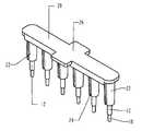
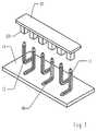
- FIG. 1the device in a first embodiment in perspective
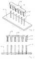
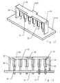
- FIG. 2the device, in perspective, after assembly onto a circuit board
- FIG. 3a side view of FIG. 2 with a partial vertical section
- FIG. 4a second embodiment of the device, in perspective
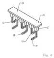
- FIG. 5the device after it has been set onto the circuit board, in perspective
- FIG. 6a side view of FIG. 5 , with a partial vertical section
- FIG. 7a representation corresponding to FIG. 5 , after the body has been pulled off
- FIG. 8a perspective view of a third embodiment of the device
- FIG. 9the device after it has been set onto the circuit board, in perspective
- FIG. 10the device after the body has been pulled off, in perspective
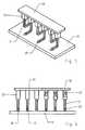
- FIG. 11a fourth embodiment of the device, in perspective,
- FIG. 12the device after it has been set onto the circuit board, in perspective
- FIG. 13a side view, of FIG. 12 with a partial vertical section
- FIG. 14the device after the body has been pulled off, in perspective
- FIG. 15a side view of FIG. 15 , with a partial vertical section
- FIGS. 16 to 20the embodiments of the device according to the state of the art, as described initially.
- FIGS. 1 to 3show a first example embodiment of the invention.
- electrically conductive pins 12are inserted into the circuit board 16 , which pins, in the example embodiment shown, are disposed in a row, with identical spacings between them. In the example embodiment shown, six pins 12 are disposed in a row. It is readily evident that, depending on the configuration of the plug-in connector, a different number of pins 12 can also be provided and/or that the pins 12 can also be arranged in two or more rows.
- the pins 12are intended for through-hole assembly or push-through assembly. Accordingly, the pins 12 are configured as straight rods, e.g. having a circular cross-section. At their end that is to be inserted into the holes of the circuit board 16 , the pins 12 are configured with a reduced diameter, so that a radial contact shoulder 18 is formed at the transition to the full cross-section of the pins 12 . Such a radial contact shoulder 18 can also be formed by an outer collar of the pin 12 .
- a body 20 made of electrically insulating plastichas the shape of a flat bar whose length corresponds to the length of the row of pins 12 .
- bushings 22are formed on in one piece; their number and mutual spacing corresponds to the number and the spacing of the pins 12 .
- the bushings 22project away from the bottom surface of the body 20 at a right angle.
- the axial length of the hollow bushings 22corresponds approximately to at least one-third of the axial length of the pins 12 ; preferably, the length amounts to approximately 1 ⁇ 2 to 2 ⁇ 3 of the length of the pins 12 .
- the bushings 22are slit axially, preferably over their entire length, by means of a diametrally continuous slit 24 .
- the wall of the bushings 22forms two tongues that are slightly elastically deformable.
- the clear inside cross-section of the bushings 22corresponds to the outside cross-section of the pins 12 .
- the width of the body 20 transverse to the row of the pins 12essentially corresponds to the outer diameter of the bushings 22 .
- its surface lying opposite the bushings 22has a widened region which forms a suction surface 26 .
- the width of this suction surface 26 and its length in the direction of the longitudinal extent of the body 20are dimensioned so that a suction surface 26 is formed, which is sufficient for the suction head of an automated assembly device to pick it up.
- the bodies 20 with the pins 12 set into the bushings 22 and held in them by a friction fitare supplied as a pre-assembled component by a feed magazine of the automated assembly device.
- the suction head of the automated assembly devicepicks up the component at the suction surface 26 , transports it to a circuit board 16 , and sets the component onto the circuit board 16 SO that the pins 12 are inserted into the holes of the circuit board 16 .
- the pins 12are inserted into the holes of the circuit board 16 until they rest against the circuit board 16 with their contact shoulder 18 .
- the inserted pins 12are soldered to the conductive paths of the circuit board 16 . After this soldering process, the body 20 is pulled off the pins, which have now been fixed in place in the circuit board 16 , counter to the clamping effect of the bushings 22 , as shown in FIGS. 2 and 3 .
- the pins 12are inserted into the circuit board 16 in a freestanding manner, without any additional component holding the pins 12 , as is the case for the body 10 of the embodiment according to the state of the art shown in FIGS. 16 to 20 .
- FIGS. 4 to 7show a second embodiment of the device. To the extent that this embodiment agrees with the first embodiment, the same reference numbers are used, and reference is made to the above description.
- the pins 12are configured for surface mounting (SMD technology.
- the pins 12which in this case have a multi-sided, particularly a four-sided cross-section, have a lower end 28 that is bent at right angles, with which the pins 12 are placed onto the circuit board 16 , in order to be soldered onto the circuit board.
- the bushings 22are also configured with a four-sided cross-section.
- the bushings 22are not slit axially; instead, the inside cross-section of the bushings 22 is dimensioned so that the pins 12 fit into the bushings 22 with a friction fit.
- the top of the entire body 20is configured with a constant width having the required size for engaging the suction head of the automated assembly device. It is therefore not necessary to configure the suction surface 26 separately.
- the component consisting of the body 20 with the inserted pins 12is set onto the circuit board 16 in the manner described above by means of the automated assembly device, as shown in FIGS. 5 and 6 .
- the pins 12are inserted into the bushings 22 so that a free path 30 remains in the bushing 22 behind the end of the pin 12 .
- This free path 30makes it possible for the pins 12 to be pressed into the respective bushings 22 to different depths when the pins 12 are set onto the circuit board 16 .
- tolerances in the axial positioning of the pins 12 with regard to the circuit board 16can be compensated for, and it is assured that the angled ends 28 of all of the pins 12 sit reliably on the circuit board so that they can be properly soldered.
- the body 20is pulled off the pins 12 , as shown in FIG. 7 .
- the pins 12 for the plug-in connectionstand freely on the circuit board 16 , without any additional auxiliary body.
- FIGS. 8 to 10show a third embodiment. To the extent that this agrees with the embodiments described above, the same reference numbers are used, and reference is made to the above description.
- the pins 12are configured for surface assembly. Accordingly, the pins 12 have a lower foot 32 with a wider diameter, with which they are set onto the solder pads of the circuit board 16 in order to be soldered to it as shown in FIG. 9 . After the soldering process, the body 20 is pulled off, as FIG. 10 shows.
- FIGS. 11 to 15A fourth embodiment is shown in FIGS. 11 to 15 .
- the same reference numbersare used for corresponding parts, and reference is made to the above description.
- the fourth embodimentagrees with the first example embodiment with regard to the configuration of the body 20 having bushings 22 and the suction surface 26 .
- the pins 12which are intended for through-hole assembly, do not have a contact shoulder in order to limit the insertion depth of the pins 12 into the holes of the circuit board 16 .
- the insertion depth of the pins 12 into the holes of the circuit board 16is limited in that a spacer 34 is formed onto each of the two ends of the body 20 , in one piece.
- the spacers 34are crosspieces directed against the circuit board at a right angle from the body 20 , i.e. parallel to the bushings 22 .
- the spacers 34extend beyond the bushings 22 in the axial direction, while the pins 12 inserted into the bushings 22 extend axially beyond the spacers in the axial direction.
- the pins 12penetrate into the holes of the circuit board 16 until the spacers 34 make contact with the circuit board 16 , as shown in FIGS. 12 and 13 .
- the insertion depth of the pins 12 into the circuit board 16is defined thereby.
- the body 20is pulled off the pins 12 , which have now been fixed in place in the circuit board 16 , in an upward direction, as shown in FIGS. 14 and 15 .
Landscapes
- Engineering & Computer Science (AREA)
- Manufacturing & Machinery (AREA)
- Microelectronics & Electronic Packaging (AREA)
- Coupling Device And Connection With Printed Circuit (AREA)
- Manufacturing Of Electrical Connectors (AREA)
Abstract
Description
- 10 body
- 12 pins
- 14 small suction plate
- 16 circuit board
- 18 contact shoulder
- 20 body
- 22 bushings
- 24 slit
- 26 suction surface
- 28 angled end
- 30 free path
- 32 foot
- 34 spacer
Claims (8)
Applications Claiming Priority (3)
| Application Number | Priority Date | Filing Date | Title |
|---|---|---|---|
| DE102006030135ADE102006030135B4 (en) | 2006-06-28 | 2006-06-28 | Device for mounting pins on a printed circuit board |
| DE102006030135 | 2006-06-28 | ||
| DE102006030135.8 | 2006-06-28 |
Publications (2)
| Publication Number | Publication Date |
|---|---|
| US20080000078A1 US20080000078A1 (en) | 2008-01-03 |
| US7735217B2true US7735217B2 (en) | 2010-06-15 |
Family
ID=38776930
Family Applications (1)
| Application Number | Title | Priority Date | Filing Date |
|---|---|---|---|
| US11/819,380Active2027-07-25US7735217B2 (en) | 2006-06-28 | 2007-06-27 | Device for assembling pins onto a circuit board background |
Country Status (2)
| Country | Link |
|---|---|
| US (1) | US7735217B2 (en) |
| DE (1) | DE102006030135B4 (en) |
Cited By (64)
| Publication number | Priority date | Publication date | Assignee | Title |
|---|---|---|---|---|
| US10123706B2 (en) | 2016-07-27 | 2018-11-13 | Align Technology, Inc. | Intraoral scanner with dental diagnostics capabilities |
| US10130445B2 (en) | 2014-09-19 | 2018-11-20 | Align Technology, Inc. | Arch expanding appliance |
| US20190046297A1 (en)* | 2017-08-11 | 2019-02-14 | Align Technology, Inc. | Devices and systems for creation of attachments for use with dental appliances and changeable shaped attachments |
| US10248883B2 (en) | 2015-08-20 | 2019-04-02 | Align Technology, Inc. | Photograph-based assessment of dental treatments and procedures |
| US10327872B2 (en) | 2014-08-15 | 2019-06-25 | Align Technology, Inc. | Field curvature model for confocal imaging apparatus with curved focal surface |
| US10383705B2 (en) | 2016-06-17 | 2019-08-20 | Align Technology, Inc. | Orthodontic appliance performance monitor |
| US10390913B2 (en) | 2018-01-26 | 2019-08-27 | Align Technology, Inc. | Diagnostic intraoral scanning |
| US10413385B2 (en) | 2004-02-27 | 2019-09-17 | Align Technology, Inc. | Method and system for providing dynamic orthodontic assessment and treatment profiles |
| US10421152B2 (en) | 2011-09-21 | 2019-09-24 | Align Technology, Inc. | Laser cutting |
| US10449016B2 (en) | 2014-09-19 | 2019-10-22 | Align Technology, Inc. | Arch adjustment appliance |
| US10456043B2 (en) | 2017-01-12 | 2019-10-29 | Align Technology, Inc. | Compact confocal dental scanning apparatus |
| US10470847B2 (en) | 2016-06-17 | 2019-11-12 | Align Technology, Inc. | Intraoral appliances with sensing |
| US10504386B2 (en) | 2015-01-27 | 2019-12-10 | Align Technology, Inc. | Training method and system for oral-cavity-imaging-and-modeling equipment |
| US10507087B2 (en) | 2016-07-27 | 2019-12-17 | Align Technology, Inc. | Methods and apparatuses for forming a three-dimensional volumetric model of a subject's teeth |
| US10517482B2 (en) | 2017-07-27 | 2019-12-31 | Align Technology, Inc. | Optical coherence tomography for orthodontic aligners |
| US10524881B2 (en) | 2010-04-30 | 2020-01-07 | Align Technology, Inc. | Patterned dental positioning appliance |
| US10537405B2 (en) | 2014-11-13 | 2020-01-21 | Align Technology, Inc. | Dental appliance with cavity for an unerupted or erupting tooth |
| US10543064B2 (en) | 2008-05-23 | 2020-01-28 | Align Technology, Inc. | Dental implant positioning |
| US10548700B2 (en) | 2016-12-16 | 2020-02-04 | Align Technology, Inc. | Dental appliance etch template |
| US10595966B2 (en) | 2016-11-04 | 2020-03-24 | Align Technology, Inc. | Methods and apparatuses for dental images |
| US10610332B2 (en) | 2012-05-22 | 2020-04-07 | Align Technology, Inc. | Adjustment of tooth position in a virtual dental model |
| US10613515B2 (en) | 2017-03-31 | 2020-04-07 | Align Technology, Inc. | Orthodontic appliances including at least partially un-erupted teeth and method of forming them |
| US10639134B2 (en) | 2017-06-26 | 2020-05-05 | Align Technology, Inc. | Biosensor performance indicator for intraoral appliances |
| US10758321B2 (en) | 2008-05-23 | 2020-09-01 | Align Technology, Inc. | Smile designer |
| US10772506B2 (en) | 2014-07-07 | 2020-09-15 | Align Technology, Inc. | Apparatus for dental confocal imaging |
| US10779718B2 (en) | 2017-02-13 | 2020-09-22 | Align Technology, Inc. | Cheek retractor and mobile device holder |
| US10813720B2 (en) | 2017-10-05 | 2020-10-27 | Align Technology, Inc. | Interproximal reduction templates |
| US10842601B2 (en) | 2008-06-12 | 2020-11-24 | Align Technology, Inc. | Dental appliance |
| US10885521B2 (en) | 2017-07-17 | 2021-01-05 | Align Technology, Inc. | Method and apparatuses for interactive ordering of dental aligners |
| US10893918B2 (en) | 2012-03-01 | 2021-01-19 | Align Technology, Inc. | Determining a dental treatment difficulty |
| US10919209B2 (en) | 2009-08-13 | 2021-02-16 | Align Technology, Inc. | Method of forming a dental appliance |
| US10980613B2 (en) | 2017-12-29 | 2021-04-20 | Align Technology, Inc. | Augmented reality enhancements for dental practitioners |
| US10993783B2 (en) | 2016-12-02 | 2021-05-04 | Align Technology, Inc. | Methods and apparatuses for customizing a rapid palatal expander |
| US11026831B2 (en) | 2016-12-02 | 2021-06-08 | Align Technology, Inc. | Dental appliance features for speech enhancement |
| US11026768B2 (en) | 1998-10-08 | 2021-06-08 | Align Technology, Inc. | Dental appliance reinforcement |
| US11045283B2 (en) | 2017-06-09 | 2021-06-29 | Align Technology, Inc. | Palatal expander with skeletal anchorage devices |
| US11083545B2 (en) | 2009-03-19 | 2021-08-10 | Align Technology, Inc. | Dental wire attachment |
| US11096763B2 (en) | 2017-11-01 | 2021-08-24 | Align Technology, Inc. | Automatic treatment planning |
| US11103330B2 (en) | 2015-12-09 | 2021-08-31 | Align Technology, Inc. | Dental attachment placement structure |
| US11116605B2 (en) | 2017-08-15 | 2021-09-14 | Align Technology, Inc. | Buccal corridor assessment and computation |
| US11123156B2 (en) | 2017-08-17 | 2021-09-21 | Align Technology, Inc. | Dental appliance compliance monitoring |
| US11213368B2 (en) | 2008-03-25 | 2022-01-04 | Align Technology, Inc. | Reconstruction of non-visible part of tooth |
| US11219506B2 (en) | 2017-11-30 | 2022-01-11 | Align Technology, Inc. | Sensors for monitoring oral appliances |
| US11273011B2 (en) | 2016-12-02 | 2022-03-15 | Align Technology, Inc. | Palatal expanders and methods of expanding a palate |
| US11376101B2 (en) | 2016-12-02 | 2022-07-05 | Align Technology, Inc. | Force control, stop mechanism, regulating structure of removable arch adjustment appliance |
| US11419702B2 (en) | 2017-07-21 | 2022-08-23 | Align Technology, Inc. | Palatal contour anchorage |
| US11426259B2 (en) | 2012-02-02 | 2022-08-30 | Align Technology, Inc. | Identifying forces on a tooth |
| US11432908B2 (en) | 2017-12-15 | 2022-09-06 | Align Technology, Inc. | Closed loop adaptive orthodontic treatment methods and apparatuses |
| US11436191B2 (en) | 2007-11-08 | 2022-09-06 | Align Technology, Inc. | Systems and methods for anonymizing patent images in relation to a clinical data file |
| US11471252B2 (en) | 2008-10-08 | 2022-10-18 | Align Technology, Inc. | Dental positioning appliance having mesh portion |
| US11534268B2 (en) | 2017-10-27 | 2022-12-27 | Align Technology, Inc. | Alternative bite adjustment structures |
| US11534974B2 (en) | 2017-11-17 | 2022-12-27 | Align Technology, Inc. | Customized fabrication of orthodontic retainers based on patient anatomy |
| US11554000B2 (en) | 2015-11-12 | 2023-01-17 | Align Technology, Inc. | Dental attachment formation structure |
| US11564777B2 (en) | 2018-04-11 | 2023-01-31 | Align Technology, Inc. | Releasable palatal expanders |
| US11576752B2 (en) | 2017-10-31 | 2023-02-14 | Align Technology, Inc. | Dental appliance having selective occlusal loading and controlled intercuspation |
| US11596502B2 (en) | 2015-12-09 | 2023-03-07 | Align Technology, Inc. | Dental attachment placement structure |
| US11612454B2 (en) | 2010-04-30 | 2023-03-28 | Align Technology, Inc. | Individualized orthodontic treatment index |
| US11633268B2 (en) | 2017-07-27 | 2023-04-25 | Align Technology, Inc. | Tooth shading, transparency and glazing |
| US11717384B2 (en) | 2007-05-25 | 2023-08-08 | Align Technology, Inc. | Dental appliance with eruption tabs |
| US11931222B2 (en) | 2015-11-12 | 2024-03-19 | Align Technology, Inc. | Dental attachment formation structures |
| US11937991B2 (en) | 2018-03-27 | 2024-03-26 | Align Technology, Inc. | Dental attachment placement structure |
| US11996181B2 (en) | 2017-06-16 | 2024-05-28 | Align Technology, Inc. | Automatic detection of tooth type and eruption status |
| US12090020B2 (en) | 2017-03-27 | 2024-09-17 | Align Technology, Inc. | Apparatuses and methods assisting in dental therapies |
| US12171575B2 (en) | 2017-10-04 | 2024-12-24 | Align Technology, Inc. | Intraoral systems and methods for sampling soft-tissue |
Families Citing this family (8)
| Publication number | Priority date | Publication date | Assignee | Title |
|---|---|---|---|---|
| DE102008057764A1 (en) | 2008-11-17 | 2010-05-20 | Wilo Se | Connecting support for solder pins |
| DE102009017523A1 (en)* | 2009-04-17 | 2010-10-28 | Phoenix Contact Gmbh & Co. Kg | Device for mounting pin on printed circuit board, has insulating body with receiving element for receiving region of pin, where receiving element with longitudinal axis is arranged at angle to suction surface of body |
| US8691075B2 (en)* | 2009-12-30 | 2014-04-08 | Roche Diagnostics Operations, Inc. | Method for measuring analyte concentration in a liquid sample |
| US9276337B2 (en) | 2012-12-21 | 2016-03-01 | Continental Automotive Systems, Inc. | Dynamically stable surface mount post header |
| JP6896381B2 (en) | 2015-07-10 | 2021-06-30 | 花王株式会社 | Hair cosmetics |
| CN106667389A (en)* | 2017-01-13 | 2017-05-17 | 常熟市亿盛日用品有限公司 | Mop head body assembling mechanism for mop head big plate assembly |
| CN114012384B (en)* | 2021-11-12 | 2023-01-17 | 昆山派胜智能科技有限公司 | Crossed roller assembling device and method |
| CN117219522B (en)* | 2023-10-17 | 2024-08-02 | 深圳市同和光电科技有限公司 | Production method of multiple detection type high-qualification rate infrared receiving chip |
Citations (13)
| Publication number | Priority date | Publication date | Assignee | Title |
|---|---|---|---|---|
| US2877441A (en)* | 1955-04-06 | 1959-03-10 | Malco Tool & Mfg Co | Terminal pin |
| US4046445A (en)* | 1976-08-23 | 1977-09-06 | International Telephone And Telegraph Corporation | Spring bushing for conductive back-plane connection |
| US4620757A (en)* | 1984-12-26 | 1986-11-04 | Brintec Systems Corporation | Connector socket |
| US4892449A (en)* | 1988-03-01 | 1990-01-09 | Northrop Corporation | Releasable fastener with gauge, and method |
| US5147209A (en) | 1990-04-16 | 1992-09-15 | Mckenzie Socket Technology, Inc. | Intermediary adapter-connector |
| US5373626A (en)* | 1993-01-06 | 1994-12-20 | Elco Corporation | Removable pin carrier |
| DE4422787A1 (en) | 1993-06-29 | 1995-01-12 | Autosplice Inc | Pins attached to the surface of printed circuit boards |
| GB2284948A (en) | 1993-12-02 | 1995-06-21 | Whitaker Corp | Surface mount connector and method of making same |
| US5439400A (en) | 1993-07-01 | 1995-08-08 | Methode Electronics, Inc. | Disposable electrical connector header |
| US5509192A (en)* | 1993-03-30 | 1996-04-23 | Ando Electric Co., Ltd. | Apparatus for press-fitting connectors into printed boards |
| US5571022A (en)* | 1994-04-11 | 1996-11-05 | The Whitaker Corporation | Electrical connector suction platform for facilitating picking |
| US5643016A (en)* | 1995-07-28 | 1997-07-01 | The Whitaker Corporation | Electrical connector assembly with contact retention and removal system |
| US5655930A (en)* | 1994-12-14 | 1997-08-12 | Molex Incorporated | Electrical pin field on a printed circuit board |
- 2006
- 2006-06-28DEDE102006030135Apatent/DE102006030135B4/enactiveActive
- 2007
- 2007-06-27USUS11/819,380patent/US7735217B2/enactiveActive
Patent Citations (13)
| Publication number | Priority date | Publication date | Assignee | Title |
|---|---|---|---|---|
| US2877441A (en)* | 1955-04-06 | 1959-03-10 | Malco Tool & Mfg Co | Terminal pin |
| US4046445A (en)* | 1976-08-23 | 1977-09-06 | International Telephone And Telegraph Corporation | Spring bushing for conductive back-plane connection |
| US4620757A (en)* | 1984-12-26 | 1986-11-04 | Brintec Systems Corporation | Connector socket |
| US4892449A (en)* | 1988-03-01 | 1990-01-09 | Northrop Corporation | Releasable fastener with gauge, and method |
| US5147209A (en) | 1990-04-16 | 1992-09-15 | Mckenzie Socket Technology, Inc. | Intermediary adapter-connector |
| US5373626A (en)* | 1993-01-06 | 1994-12-20 | Elco Corporation | Removable pin carrier |
| US5509192A (en)* | 1993-03-30 | 1996-04-23 | Ando Electric Co., Ltd. | Apparatus for press-fitting connectors into printed boards |
| DE4422787A1 (en) | 1993-06-29 | 1995-01-12 | Autosplice Inc | Pins attached to the surface of printed circuit boards |
| US5439400A (en) | 1993-07-01 | 1995-08-08 | Methode Electronics, Inc. | Disposable electrical connector header |
| GB2284948A (en) | 1993-12-02 | 1995-06-21 | Whitaker Corp | Surface mount connector and method of making same |
| US5571022A (en)* | 1994-04-11 | 1996-11-05 | The Whitaker Corporation | Electrical connector suction platform for facilitating picking |
| US5655930A (en)* | 1994-12-14 | 1997-08-12 | Molex Incorporated | Electrical pin field on a printed circuit board |
| US5643016A (en)* | 1995-07-28 | 1997-07-01 | The Whitaker Corporation | Electrical connector assembly with contact retention and removal system |
Cited By (91)
| Publication number | Priority date | Publication date | Assignee | Title |
|---|---|---|---|---|
| US11026768B2 (en) | 1998-10-08 | 2021-06-08 | Align Technology, Inc. | Dental appliance reinforcement |
| US10413385B2 (en) | 2004-02-27 | 2019-09-17 | Align Technology, Inc. | Method and system for providing dynamic orthodontic assessment and treatment profiles |
| US11717384B2 (en) | 2007-05-25 | 2023-08-08 | Align Technology, Inc. | Dental appliance with eruption tabs |
| US11436191B2 (en) | 2007-11-08 | 2022-09-06 | Align Technology, Inc. | Systems and methods for anonymizing patent images in relation to a clinical data file |
| US11213368B2 (en) | 2008-03-25 | 2022-01-04 | Align Technology, Inc. | Reconstruction of non-visible part of tooth |
| US10543064B2 (en) | 2008-05-23 | 2020-01-28 | Align Technology, Inc. | Dental implant positioning |
| US10758321B2 (en) | 2008-05-23 | 2020-09-01 | Align Technology, Inc. | Smile designer |
| US10842601B2 (en) | 2008-06-12 | 2020-11-24 | Align Technology, Inc. | Dental appliance |
| US11471252B2 (en) | 2008-10-08 | 2022-10-18 | Align Technology, Inc. | Dental positioning appliance having mesh portion |
| US11083545B2 (en) | 2009-03-19 | 2021-08-10 | Align Technology, Inc. | Dental wire attachment |
| US10919209B2 (en) | 2009-08-13 | 2021-02-16 | Align Technology, Inc. | Method of forming a dental appliance |
| US11612454B2 (en) | 2010-04-30 | 2023-03-28 | Align Technology, Inc. | Individualized orthodontic treatment index |
| US10524881B2 (en) | 2010-04-30 | 2020-01-07 | Align Technology, Inc. | Patterned dental positioning appliance |
| US10421152B2 (en) | 2011-09-21 | 2019-09-24 | Align Technology, Inc. | Laser cutting |
| US10828719B2 (en) | 2011-09-21 | 2020-11-10 | Align Technology, Inc. | Laser cutting |
| US11426259B2 (en) | 2012-02-02 | 2022-08-30 | Align Technology, Inc. | Identifying forces on a tooth |
| US10893918B2 (en) | 2012-03-01 | 2021-01-19 | Align Technology, Inc. | Determining a dental treatment difficulty |
| US10610332B2 (en) | 2012-05-22 | 2020-04-07 | Align Technology, Inc. | Adjustment of tooth position in a virtual dental model |
| US11369271B2 (en) | 2014-07-07 | 2022-06-28 | Align Technology, Inc. | Apparatus for dental imaging |
| US10772506B2 (en) | 2014-07-07 | 2020-09-15 | Align Technology, Inc. | Apparatus for dental confocal imaging |
| US10835128B2 (en) | 2014-07-07 | 2020-11-17 | Align Technology, Inc. | Apparatus for dental confocal imaging |
| US10507088B2 (en) | 2014-08-15 | 2019-12-17 | Align Technology, Inc. | Imaging apparatus with simplified optical design |
| US10507089B2 (en) | 2014-08-15 | 2019-12-17 | Align Technology, Inc. | Imaging apparatus with simplified optical design |
| US10327872B2 (en) | 2014-08-15 | 2019-06-25 | Align Technology, Inc. | Field curvature model for confocal imaging apparatus with curved focal surface |
| US10624720B1 (en) | 2014-08-15 | 2020-04-21 | Align Technology, Inc. | Imaging apparatus with temperature compensation |
| US10952827B2 (en) | 2014-08-15 | 2021-03-23 | Align Technology, Inc. | Calibration of an intraoral scanner |
| US11638629B2 (en) | 2014-09-19 | 2023-05-02 | Align Technology, Inc. | Arch expanding appliance |
| US10130445B2 (en) | 2014-09-19 | 2018-11-20 | Align Technology, Inc. | Arch expanding appliance |
| US11744677B2 (en) | 2014-09-19 | 2023-09-05 | Align Technology, Inc. | Arch adjustment appliance |
| US10449016B2 (en) | 2014-09-19 | 2019-10-22 | Align Technology, Inc. | Arch adjustment appliance |
| US10537405B2 (en) | 2014-11-13 | 2020-01-21 | Align Technology, Inc. | Dental appliance with cavity for an unerupted or erupting tooth |
| US11037466B2 (en) | 2015-01-27 | 2021-06-15 | Align Technology, Inc. | Training method and system for oral-cavity-imaging-and-modeling equipment |
| US10504386B2 (en) | 2015-01-27 | 2019-12-10 | Align Technology, Inc. | Training method and system for oral-cavity-imaging-and-modeling equipment |
| US10248883B2 (en) | 2015-08-20 | 2019-04-02 | Align Technology, Inc. | Photograph-based assessment of dental treatments and procedures |
| US11042774B2 (en) | 2015-08-20 | 2021-06-22 | Align Technology, Inc. | Photograph-based assessment of dental treatments and procedures |
| US11931222B2 (en) | 2015-11-12 | 2024-03-19 | Align Technology, Inc. | Dental attachment formation structures |
| US11554000B2 (en) | 2015-11-12 | 2023-01-17 | Align Technology, Inc. | Dental attachment formation structure |
| US11596502B2 (en) | 2015-12-09 | 2023-03-07 | Align Technology, Inc. | Dental attachment placement structure |
| US11103330B2 (en) | 2015-12-09 | 2021-08-31 | Align Technology, Inc. | Dental attachment placement structure |
| US10470847B2 (en) | 2016-06-17 | 2019-11-12 | Align Technology, Inc. | Intraoral appliances with sensing |
| US10383705B2 (en) | 2016-06-17 | 2019-08-20 | Align Technology, Inc. | Orthodontic appliance performance monitor |
| US11612455B2 (en) | 2016-06-17 | 2023-03-28 | Align Technology, Inc. | Orthodontic appliance performance monitor |
| US10888396B2 (en) | 2016-06-17 | 2021-01-12 | Align Technology, Inc. | Intraoral appliances with proximity and contact sensing |
| US10606911B2 (en) | 2016-07-27 | 2020-03-31 | Align Technology, Inc. | Intraoral scanner with dental diagnostics capabilities |
| US10888400B2 (en) | 2016-07-27 | 2021-01-12 | Align Technology, Inc. | Methods and apparatuses for forming a three-dimensional volumetric model of a subject's teeth |
| US10123706B2 (en) | 2016-07-27 | 2018-11-13 | Align Technology, Inc. | Intraoral scanner with dental diagnostics capabilities |
| US10507087B2 (en) | 2016-07-27 | 2019-12-17 | Align Technology, Inc. | Methods and apparatuses for forming a three-dimensional volumetric model of a subject's teeth |
| US10528636B2 (en) | 2016-07-27 | 2020-01-07 | Align Technology, Inc. | Methods for dental diagnostics |
| US10585958B2 (en) | 2016-07-27 | 2020-03-10 | Align Technology, Inc. | Intraoral scanner with dental diagnostics capabilities |
| US10509838B2 (en) | 2016-07-27 | 2019-12-17 | Align Technology, Inc. | Methods and apparatuses for forming a three-dimensional volumetric model of a subject's teeth |
| US10380212B2 (en) | 2016-07-27 | 2019-08-13 | Align Technology, Inc. | Methods and apparatuses for forming a three-dimensional volumetric model of a subject's teeth |
| US11191617B2 (en) | 2016-11-04 | 2021-12-07 | Align Technology, Inc. | Methods and apparatuses for dental images |
| US10595966B2 (en) | 2016-11-04 | 2020-03-24 | Align Technology, Inc. | Methods and apparatuses for dental images |
| US10932885B2 (en) | 2016-11-04 | 2021-03-02 | Align Technology, Inc. | Methods and apparatuses for dental images |
| US11273011B2 (en) | 2016-12-02 | 2022-03-15 | Align Technology, Inc. | Palatal expanders and methods of expanding a palate |
| US11026831B2 (en) | 2016-12-02 | 2021-06-08 | Align Technology, Inc. | Dental appliance features for speech enhancement |
| US11376101B2 (en) | 2016-12-02 | 2022-07-05 | Align Technology, Inc. | Force control, stop mechanism, regulating structure of removable arch adjustment appliance |
| US10993783B2 (en) | 2016-12-02 | 2021-05-04 | Align Technology, Inc. | Methods and apparatuses for customizing a rapid palatal expander |
| US10548700B2 (en) | 2016-12-16 | 2020-02-04 | Align Technology, Inc. | Dental appliance etch template |
| US10918286B2 (en) | 2017-01-12 | 2021-02-16 | Align Technology, Inc. | Compact confocal dental scanning apparatus |
| US11712164B2 (en) | 2017-01-12 | 2023-08-01 | Align Technology, Inc. | Intraoral scanner with moveable opto-mechanical module |
| US10456043B2 (en) | 2017-01-12 | 2019-10-29 | Align Technology, Inc. | Compact confocal dental scanning apparatus |
| US10779718B2 (en) | 2017-02-13 | 2020-09-22 | Align Technology, Inc. | Cheek retractor and mobile device holder |
| US12090020B2 (en) | 2017-03-27 | 2024-09-17 | Align Technology, Inc. | Apparatuses and methods assisting in dental therapies |
| US10613515B2 (en) | 2017-03-31 | 2020-04-07 | Align Technology, Inc. | Orthodontic appliances including at least partially un-erupted teeth and method of forming them |
| US11045283B2 (en) | 2017-06-09 | 2021-06-29 | Align Technology, Inc. | Palatal expander with skeletal anchorage devices |
| US11996181B2 (en) | 2017-06-16 | 2024-05-28 | Align Technology, Inc. | Automatic detection of tooth type and eruption status |
| US10639134B2 (en) | 2017-06-26 | 2020-05-05 | Align Technology, Inc. | Biosensor performance indicator for intraoral appliances |
| US10885521B2 (en) | 2017-07-17 | 2021-01-05 | Align Technology, Inc. | Method and apparatuses for interactive ordering of dental aligners |
| US11419702B2 (en) | 2017-07-21 | 2022-08-23 | Align Technology, Inc. | Palatal contour anchorage |
| US10842380B2 (en) | 2017-07-27 | 2020-11-24 | Align Technology, Inc. | Methods and systems for imaging orthodontic aligners |
| US11633268B2 (en) | 2017-07-27 | 2023-04-25 | Align Technology, Inc. | Tooth shading, transparency and glazing |
| US10517482B2 (en) | 2017-07-27 | 2019-12-31 | Align Technology, Inc. | Optical coherence tomography for orthodontic aligners |
| US12274597B2 (en)* | 2017-08-11 | 2025-04-15 | Align Technology, Inc. | Dental attachment template tray systems |
| US20190046297A1 (en)* | 2017-08-11 | 2019-02-14 | Align Technology, Inc. | Devices and systems for creation of attachments for use with dental appliances and changeable shaped attachments |
| US11116605B2 (en) | 2017-08-15 | 2021-09-14 | Align Technology, Inc. | Buccal corridor assessment and computation |
| US11123156B2 (en) | 2017-08-17 | 2021-09-21 | Align Technology, Inc. | Dental appliance compliance monitoring |
| US12171575B2 (en) | 2017-10-04 | 2024-12-24 | Align Technology, Inc. | Intraoral systems and methods for sampling soft-tissue |
| US10813720B2 (en) | 2017-10-05 | 2020-10-27 | Align Technology, Inc. | Interproximal reduction templates |
| US11534268B2 (en) | 2017-10-27 | 2022-12-27 | Align Technology, Inc. | Alternative bite adjustment structures |
| US11576752B2 (en) | 2017-10-31 | 2023-02-14 | Align Technology, Inc. | Dental appliance having selective occlusal loading and controlled intercuspation |
| US11096763B2 (en) | 2017-11-01 | 2021-08-24 | Align Technology, Inc. | Automatic treatment planning |
| US11534974B2 (en) | 2017-11-17 | 2022-12-27 | Align Technology, Inc. | Customized fabrication of orthodontic retainers based on patient anatomy |
| US11219506B2 (en) | 2017-11-30 | 2022-01-11 | Align Technology, Inc. | Sensors for monitoring oral appliances |
| US11432908B2 (en) | 2017-12-15 | 2022-09-06 | Align Technology, Inc. | Closed loop adaptive orthodontic treatment methods and apparatuses |
| US10980613B2 (en) | 2017-12-29 | 2021-04-20 | Align Technology, Inc. | Augmented reality enhancements for dental practitioners |
| US10813727B2 (en) | 2018-01-26 | 2020-10-27 | Align Technology, Inc. | Diagnostic intraoral tracking |
| US10390913B2 (en) | 2018-01-26 | 2019-08-27 | Align Technology, Inc. | Diagnostic intraoral scanning |
| US11013581B2 (en) | 2018-01-26 | 2021-05-25 | Align Technology, Inc. | Diagnostic intraoral methods and apparatuses |
| US11937991B2 (en) | 2018-03-27 | 2024-03-26 | Align Technology, Inc. | Dental attachment placement structure |
| US11564777B2 (en) | 2018-04-11 | 2023-01-31 | Align Technology, Inc. | Releasable palatal expanders |
Also Published As
| Publication number | Publication date |
|---|---|
| DE102006030135A1 (en) | 2008-01-03 |
| DE102006030135B4 (en) | 2008-05-08 |
| US20080000078A1 (en) | 2008-01-03 |
Similar Documents
| Publication | Publication Date | Title |
|---|---|---|
| US7735217B2 (en) | Device for assembling pins onto a circuit board background | |
| US7448901B2 (en) | Surface mount poke-in connector | |
| US5607313A (en) | Surface mounted holes for printed circuit boards | |
| US9520666B2 (en) | Contact carrier with a tolerance-compensating portion | |
| US5062024A (en) | Modular connector for printed circuit boards | |
| US20110201222A1 (en) | Connector with floating terminals | |
| US20090213563A1 (en) | Interconnecting device and method used to electrically mount a daughter board to a motherboard | |
| US9246253B1 (en) | Connector with stabilization members and method of assembly | |
| US7532484B1 (en) | Electronic component assembly | |
| CN100468872C (en) | Conductive plug connector | |
| US7402066B2 (en) | Low insertion force socket with lead-in mechanism background of the invention | |
| JPH07201401A (en) | Mounting connector | |
| KR20220076520A (en) | Electronics housings for automated assembly | |
| EP1473802B1 (en) | Tab terminal | |
| JP2001217025A (en) | Terminal adapter of pcb (printed-circuit board) | |
| US6135784A (en) | LIF PGA socket | |
| KR20060126356A (en) | LIF socket connector | |
| US6843662B2 (en) | Electric connector housing supporting a plurality of solder balls and including a plurality of protruding blocks respectively supporting the plurality of solder balls | |
| CN101242039A (en) | Printed circuit board plug connecting device for tow parallel printed circuit boards | |
| JPH0622111B2 (en) | Substrate mounting light bulb and manufacturing method thereof | |
| JP2006526251A (en) | Electrical connector using conductive terminal and conductive terminal | |
| CN212011336U (en) | plug connector | |
| WO2014085558A1 (en) | Mechanical spacer with non-spring electrical connections for a multiple printed circuit board assembly | |
| US6095857A (en) | Electrical component for surface-mounting on a circuit board | |
| JP6804926B2 (en) | Electronic component module |
Legal Events
| Date | Code | Title | Description |
|---|---|---|---|
| AS | Assignment | Owner name:MC TECHNOLOGY GMBH, GERMANY Free format text:ASSIGNMENT OF ASSIGNORS INTEREST;ASSIGNOR:BORST, JOACHIM;REEL/FRAME:019534/0786 Effective date:20070614 Owner name:MC TECHNOLOGY GMBH,GERMANY Free format text:ASSIGNMENT OF ASSIGNORS INTEREST;ASSIGNOR:BORST, JOACHIM;REEL/FRAME:019534/0786 Effective date:20070614 | |
| STCF | Information on status: patent grant | Free format text:PATENTED CASE | |
| FEPP | Fee payment procedure | Free format text:PAYOR NUMBER ASSIGNED (ORIGINAL EVENT CODE: ASPN); ENTITY STATUS OF PATENT OWNER: LARGE ENTITY | |
| FPAY | Fee payment | Year of fee payment:4 | |
| MAFP | Maintenance fee payment | Free format text:PAYMENT OF MAINTENANCE FEE, 8TH YEAR, LARGE ENTITY (ORIGINAL EVENT CODE: M1552) Year of fee payment:8 | |
| MAFP | Maintenance fee payment | Free format text:PAYMENT OF MAINTENANCE FEE, 12TH YEAR, LARGE ENTITY (ORIGINAL EVENT CODE: M1553); ENTITY STATUS OF PATENT OWNER: LARGE ENTITY Year of fee payment:12 |