US7735164B1 - Disposable patient transfer mattress - Google Patents
Disposable patient transfer mattressDownload PDFInfo
- Publication number
- US7735164B1 US7735164B1US11/999,738US99973807AUS7735164B1US 7735164 B1US7735164 B1US 7735164B1US 99973807 AUS99973807 AUS 99973807AUS 7735164 B1US7735164 B1US 7735164B1
- Authority
- US
- United States
- Prior art keywords
- mattress
- receptacle
- air
- sheet
- top sheet
- Prior art date
- Legal status (The legal status is an assumption and is not a legal conclusion. Google has not performed a legal analysis and makes no representation as to the accuracy of the status listed.)
- Active, expires
Links
- 239000000463materialSubstances0.000claimsabstractdescription45
- 238000003466weldingMethods0.000claimsabstractdescription24
- 239000004744fabricSubstances0.000claimsabstractdescription17
- 239000004677NylonSubstances0.000claimsdescription12
- 229920001778nylonPolymers0.000claimsdescription12
- 239000004800polyvinyl chlorideSubstances0.000claimsdescription10
- 229920000915polyvinyl chloridePolymers0.000claimsdescription8
- 229920000728polyesterPolymers0.000claimsdescription6
- 230000002093peripheral effectEffects0.000claimsdescription5
- 229920001634CopolyesterPolymers0.000claimsdescription4
- 238000005304joiningMethods0.000claimsdescription3
- 239000004676acrylonitrile butadiene styreneSubstances0.000claimsdescription2
- 239000012779reinforcing materialSubstances0.000claims4
- XECAHXYUAAWDEL-UHFFFAOYSA-Nacrylonitrile butadiene styreneChemical compoundC=CC=C.C=CC#N.C=CC1=CC=CC=C1XECAHXYUAAWDEL-UHFFFAOYSA-N0.000claims1
- 229920000122acrylonitrile butadiene styrenePolymers0.000claims1
- 230000003213activating effectEffects0.000claims1
- 238000012423maintenanceMethods0.000claims1
- 238000000034methodMethods0.000description17
- 238000004140cleaningMethods0.000description6
- 230000000694effectsEffects0.000description5
- 239000000356contaminantSubstances0.000description4
- 238000005339levitationMethods0.000description4
- 238000005096rolling processMethods0.000description4
- 238000009826distributionMethods0.000description3
- 238000004519manufacturing processMethods0.000description3
- 239000002245particleSubstances0.000description3
- 208000008589ObesityDiseases0.000description2
- 238000011109contaminationMethods0.000description2
- 229920000515polycarbonatePolymers0.000description2
- 239000004417polycarbonateSubstances0.000description2
- 238000009877renderingMethods0.000description2
- 238000001356surgical procedureMethods0.000description2
- 229920004142LEXAN™Polymers0.000description1
- 208000002847Surgical WoundDiseases0.000description1
- WYTGDNHDOZPMIW-RCBQFDQVSA-NalstonineNatural productsC1=CC2=C3C=CC=CC3=NC2=C2N1C[C@H]1[C@H](C)OC=C(C(=O)OC)[C@H]1C2WYTGDNHDOZPMIW-RCBQFDQVSA-N0.000description1
- 230000000845anti-microbial effectEffects0.000description1
- 239000004599antimicrobialSubstances0.000description1
- 230000000903blocking effectEffects0.000description1
- 239000011248coating agentSubstances0.000description1
- 238000000576coating methodMethods0.000description1
- 208000012696congenital leptin deficiencyDiseases0.000description1
- 238000012864cross contaminationMethods0.000description1
- 238000006073displacement reactionMethods0.000description1
- 229920005839ecoflex®Polymers0.000description1
- 238000010438heat treatmentMethods0.000description1
- 238000003384imaging methodMethods0.000description1
- 238000003780insertionMethods0.000description1
- 230000037431insertionEffects0.000description1
- 238000002595magnetic resonance imagingMethods0.000description1
- 239000012528membraneSubstances0.000description1
- 229910052751metalInorganic materials0.000description1
- 239000002184metalSubstances0.000description1
- 150000002739metalsChemical class0.000description1
- 208000001022morbid obesityDiseases0.000description1
- 230000000474nursing effectEffects0.000description1
- 235000020824obesityNutrition0.000description1
- 239000002861polymer materialSubstances0.000description1
- 238000007789sealingMethods0.000description1
- 238000003860storageMethods0.000description1
Images


Classifications
- A—HUMAN NECESSITIES
- A61—MEDICAL OR VETERINARY SCIENCE; HYGIENE
- A61G—TRANSPORT, PERSONAL CONVEYANCES, OR ACCOMMODATION SPECIALLY ADAPTED FOR PATIENTS OR DISABLED PERSONS; OPERATING TABLES OR CHAIRS; CHAIRS FOR DENTISTRY; FUNERAL DEVICES
- A61G7/00—Beds specially adapted for nursing; Devices for lifting patients or disabled persons
- A61G7/10—Devices for lifting patients or disabled persons, e.g. special adaptations of hoists thereto
- A61G7/1013—Lifting of patients by
- A61G7/1021—Inflatable cushions
- A—HUMAN NECESSITIES
- A61—MEDICAL OR VETERINARY SCIENCE; HYGIENE
- A61G—TRANSPORT, PERSONAL CONVEYANCES, OR ACCOMMODATION SPECIALLY ADAPTED FOR PATIENTS OR DISABLED PERSONS; OPERATING TABLES OR CHAIRS; CHAIRS FOR DENTISTRY; FUNERAL DEVICES
- A61G7/00—Beds specially adapted for nursing; Devices for lifting patients or disabled persons
- A61G7/10—Devices for lifting patients or disabled persons, e.g. special adaptations of hoists thereto
- A61G7/1025—Lateral movement of patients, e.g. horizontal transfer
- A61G7/1026—Sliding sheets or mats
- A—HUMAN NECESSITIES
- A61—MEDICAL OR VETERINARY SCIENCE; HYGIENE
- A61G—TRANSPORT, PERSONAL CONVEYANCES, OR ACCOMMODATION SPECIALLY ADAPTED FOR PATIENTS OR DISABLED PERSONS; OPERATING TABLES OR CHAIRS; CHAIRS FOR DENTISTRY; FUNERAL DEVICES
- A61G2200/00—Information related to the kind of patient or his position
- A61G2200/30—Specific positions of the patient
- A61G2200/32—Specific positions of the patient lying
- A—HUMAN NECESSITIES
- A61—MEDICAL OR VETERINARY SCIENCE; HYGIENE
- A61G—TRANSPORT, PERSONAL CONVEYANCES, OR ACCOMMODATION SPECIALLY ADAPTED FOR PATIENTS OR DISABLED PERSONS; OPERATING TABLES OR CHAIRS; CHAIRS FOR DENTISTRY; FUNERAL DEVICES
- A61G2203/00—General characteristics of devices
- A61G2203/70—General characteristics of devices with special adaptations, e.g. for safety or comfort
- A61G2203/90—General characteristics of devices with special adaptations, e.g. for safety or comfort biodegradable
Definitions
- the present inventionrelates generally to an apparatus for transferring bed patients, and more particularly to a disposable inflatable mattress for moving a patient on a cushion of air, and to a system including an inflatable mattress connected to an air supply by a quick release connector.
- Non-ambulatory patients who must be supported and moved in a patient facility such as a hospital or a nursing homepresent substantial challenges when a course of treatment for such patients calls for movement from one location to another.
- a patientmay need to be moved from a hospital bed, which must remain in the patient's room, to a stretcher and then from the stretcher to a treatment location such as a surgical table in an operating room.
- the reverse patient handling sequencemust occur; i.e., the patient must be moved from the surgical table, which remains in the operating room, to a stretcher which travels to the patient's hospital room, and then from the stretcher back onto the bed in the hospital room.
- the patientIn a very large percentage of such occurrences the patient must be handled in a fashion which requires only a minimum of movement of the patient with respect to a supporting surface. In the case of a patient being returned to a hospital room following surgery, for example, the patient's body may not be able to withstand the stresses and strains of being lifted from a stretcher to the bed when one or even several hospital personnel combine their efforts to make such a transfer.
- the staffmust perform the task of lifting and/or sliding such a patient because in nearly all instances the patient, due to the physical condition of obesity and/or illness, simply cannot personally do the task.
- the manipulation of such a personrequires a plurality of hospital staff since such manipulation is impossible to perform by a single person such as a floor nurse assigned to the patient's room.
- Such transfersmust be planned in advance for a specific time and a number of hospital staff must be notified and arrange their schedules so that all staff will be available at the same time.
- many hospital staffare females and many of these persons are rather slight of stature. As a result, a half dozen or more such persons may need to be assembled.
- an air mattressonto which the patient is placed while in his bed and which is then placed onto a wheeler.
- a problem common to all such devicesis that invariably the air mattress has the general characteristic of a balloon, in the sense that when one area is indented another remote area will bulge, thus creating an unstable condition. If for example a stretcher carrying an obese person makes a sharp turn during a trip to or from a treatment location, such an obese person will tend to roll toward the outside of the turn due to the instability of such a conventional mattress. The more the patient rolls, the more the mattress portion toward which the rolling movement occurs will depress, and the greater will be the expansion of the mattress on the other side of the patient.
- the conventional mattressreinforces the undesirable rolling movement and is unstable. Since much of the time the patient is incapable of stopping the rolling action by himself, the patient may roll off the stretcher onto the floor with disastrous consequences. Indeed, even in the instance of a patient who is capable of moving himself to some degree about his longitudinal body axis the same disastrous result may occur because the displacement of air from one edge portion of the mattress to the opposite edge portion creates in effect a tipping cradle. Only if the patient lies perfectly flat and perfectly still on the stretcher, and no roadway depressions or blocking objects, such as excess hospital beds stored in a hallway, are encountered can the probabilities of an accident be lessened.
- a still further problem with prior art apparatusis control of contamination. Often, a tedious cleaning protocol follows after such use to avoid cross-contamination. Cleaning is particularly difficult because contaminant particles can penetrate into the mattress material, and when the mattress is inflated, contaminant particles may be expelled into the air. The high cost of many prior art air cushions requires their re-use.
- a still further problem with prior art systemsis the difficulty of connecting and disconnecting an air supply from the air mattress.
- some prior art air mattressesrequire inserting an air supply hose into a fabric sleeve in the air mattress in order to inflate the mattress. This requires finding the sleeve in the uninflated mattress, separating the fabric to open up the sleeve and then inserting the hose far enough into the sleeve for the connection to be effective.
- a disposable patient transfer mattresscomprises: a rectangular top sheet; a rectangular bottom sheet; internal baffles; and a receptacle configured to receive a connector for supplying air to inflate the mattress.
- the bottom sheetcorresponds to the top sheet, dud the periphery of the bottom sheet is joined to the periphery of the top sheet.
- the internal bafflesextend between the top sheet and the bottom sheet.
- Each baffleis a rectangular sheet with first and second parallel edges, and each baffle is joined to the top sheet along the first edge and to the bottom sheet along the second edge.
- the bafflesare configured to divide the internal volume of the mattress into a plurality of connected chambers and impart structural integrity and rigidity to the mattress.
- the bottom sheethas a plurality of holes configured to provide a continuous cushion of air under the mattress when the mattress is inflated.
- the receptacleis integrated into the top sheet.
- the top sheet, bottom sheet, and internal bafflesare made of fabric backed with a thermally weldable material, where the thermally weldable material faces the interior of the mattress for facilitating thermal welding of the baffles to the top surface and the bottom surface.
- the thermal welding processis preferably ultrasonic welding.
- An example of the fabric and backingis 70 dernier nylon fabric backed with polyvinylchloride (PVC), where the nylon fabric provides strength and the PVC allows for air tight joining by thermal welding.
- the receptaclemay be made of rubberized nylon and can be thermally welded to the top sheet. Due to the low cost of materials and manufacturing, the air mattress of the invention is viable as a single use—disposable—air mattress.
- the disposable air mattress described hereinare made of biodegradable materials.
- the thermally weldable material used in the top and bottom sheets and the bafflesmay be made of aliphatic aromatic copolyesters.
- a patient transfer systemcomprises: an inflatable mattress having a bottom surface with a plurality of holes configured to provide a continuous cushion of air under the mattress when the mattress is inflated; a receptacle integrated into the mattress; an air supply cart for inflating the mattress; and a connector attached to the air supply cart by a flexible hose, where the connector and receptacle are configured for ease of connecting and disconnecting the air supply from the air mattress.
- the receptacleis made of a rubber-like material, and comprises: a disc with a centrally positioned opening through which air can be pumped into the mattress; a U-shaped groove on the upper surface of the disc, centered on the opening; and a slot positioned on the perimeter of the disc at the center of the open part of the U in the U-shaped groove.
- the connectoris made of a rigid material, and comprises: a tube; a rim at one end of the tube, where the rim extends radially out from the end of the tube; and a key on the periphery of the rim.
- the connectoris mated to the receptacle by sliding the rim into the groove until the key is in the slot.
- the key and the slotare configured so that when the key is in the slot the upper surface of the receptacle and the rim of the connector are kept in contact while air is pumped into the mattress.
- FIG. 1illustrates a patient transfer system according to the present invention as applied to a stretcher.
- FIG. 2illustrates an air supply cart according to the present invention.
- FIG. 3illustrates patient movement between beds using the patient transfer system according to the present invention.
- FIG. 4illustrates a top view of an air mattress according to the present invention.
- FIG. 5illustrates a bottom view of the air mattress of FIG. 4 .
- FIG. 6is a cross-sectional view of the air mattress of FIGS. 4 and 5 .
- FIG. 7illustrates a connector for attaching an air supply hose to the mattress.
- FIG. 8illustrates a receptacle on the mattress for receiving the connector of FIG. 7 .
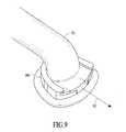
- FIG. 9illustrates the connector of FIG. 7 mated with the receptacle of FIG. 8 .
- FIG. 1An embodiment of the present invention is illustrated generally in FIG. 1 as applied to a planar item 12 , which in this case is represented as a stretcher.
- a portable air supply cart 20is provided for supplying air to an air mattress 11 .
- the portable air supply cart 20is connected to the air mattress 11 by means of a flexible hose 28 with a connector 70 which is received by a receptacle 80 integrated into the air mattress 11 .
- the term “air” as used in the present disclosurerefers to air or any other gas that can be used to inflate an inflatable mattress. “Air mattress” therefore refers to a mattress that can be inflated with any such gas.
- the planar item 12can be any type of bed/surface for supporting a patient, such as a stretcher or hospital bed, and will be referred to herein as a bed apparatus.
- the inflatable air mattress 11can be positioned on a firm surface such as planar item 12 illustrated in FIG. 1 , or alternatively the air mattress 11 can be placed either on top of or under a non-inflatable mattress. These alternative configurations are shown and discussed in reference to FIG. 3 .
- the air mattressis moved using handles 13 .
- the receptacle 80is shown in FIG. 1 as being positioned in the top surface of the mattress 11 ; this position is preferred, although the receptacle may be positioned elsewhere.
- the portable air supply cart 20includes air supply system 21 , compartment 22 for storage of one or more uninflated, hermetically packaged, air mattresses 23 , and a structural frame 24 to which wheels 25 and a handle 26 are attached.
- the frame 24supports the air supply system 21 and the compartment 22 , and the handle 26 allows a user to conveniently maneuver the cart.
- the air supply system 21includes a gas/air blower 27 (the housing of the air supply system has been cut-away to show the blower), a gas/air hose 28 attached to the blower at one end, a power supply 29 including a rechargeable battery, and a power cord 291 .
- the cord 291can be plugged into an AC outlet for running the blower, and/or for charging the battery.
- the blowercan be operated from the battery without the need to plug the cord into an outlet, providing the battery is sufficiently charged.
- the supply 29also includes an on-off switch 292 , and, in some embodiments, a display/indicator 293 for showing the degree of charge stored in the battery.
- the hose 28has a connector 70 on a distal end for connection to a receptacle 80 on the air mattress 11 .
- an auxiliary power switch 294is integrated into the connector 70 .
- the power switch 294may be a rocker-type on-off switch, or a membrane switch. When the switch 294 is positioned in the connector 70 , an electrical cable (not shown) runs along the hose 28 , making electrical connection between the switch 294 and the supply 29 .
- various portions of the cart 20may be coated in part, or completely, with an antimicrobial coating, indicated symbolically with dots on a portion 201 .
- FIG. 3illustrates a system of the present invention in operation.
- a patient 31is on a first bed apparatus 32 , and is to be moved onto an adjacent second bed apparatus 33 .
- the patient 31has been placed on an inflatable mattress 11 for providing an air cushion 34 .
- the supply system 21has a flexible hose 28 connected to the air mattress 11 and is supplying a gas, a portion of which is forced out of exit holes 51 , causing the air mattress 11 to float on a cushion of air/gas 34 .
- the cushion of air/gas 34must be continuous under the mattress 11 .
- An attendantcan at this stage, move the patient on said air mattress 11 over onto the bed 33 .
- FIG. 3also illustrates placing the air mattress either above or below a non-inflatable mattress.
- Dashed outline 35illustrates a non-inflatable mattress on which air mattress 11 is placed.
- a similar non-inflatable mattress 36can also be placed on bed 33 .
- the air mattress 11can be placed under a non-inflatable mattress 37 upon which the patient 31 is placed.
- Any combination of inflatable air mattresses as described herein with non-inflatable mattresses on any of the various beds described in the present disclosureare included in the present invention.
- the air mattress 11is comprised of corresponding continuous rectangular top and bottom sheets, joined at their edges.
- the air mattress 11is made in a variety of sizes, to suit the needs of hospitals, care providers, etc. Some examples of typical air mattress dimensions (when properly inflated) are: 203 cm long ⁇ 89 cm wide ⁇ 19 cm deep; 203 cm long ⁇ 99 cm wide ⁇ 19 cm deep; 203 cm long ⁇ 122 cm wide ⁇ 19 cm deep.
- FIGS. 4 and 5show the top and bottom views, respectively, of the air mattress 11 .
- the air mattress' top sheet 40is shown in FIG. 4 .
- a receptacle 80is shown integrated into the top sheet 40 , for connecting to an air supply such as portable air supply 20 . (See FIG.
- Welding seams 41 and 42are shown on the top sheet 40 . These particular seams are created when (1) internal baffles 60 (see FIG. 6 ) are welded in place (seams 42 ) and (2) the top and bottom sheets of the mattress are welded together at the perimeter (seam 41 ).
- the welding processis a thermal welding process which relies on heating the material sufficiently to form an air tight joint. For ease of manufacture, the thermal welding process is preferably an ultrasonic welding process.
- the baffles 60have the effect of controlling the flow of air through the mattress and help to maintain the functionality of the mattress, as a levitating device, when loaded with a heavy body.
- baffles 60are shown as being equally spaced and indicated as running straight across the air mattress (parallel to the short sides of the rectangular mattress), but the baffles may also be serpentine, run along the length of the mattress (i.e. perpendicular to the direction shown in FIGS. 4 and 5 ), or have some other efficacious configuration. (The baffles are discussed in more detail below and are shown in cross-section in FIG. 6 .) Having welded, rather than stitched, seams, where the baffles 60 are joined to the top and bottom sheets of the mattress, helps to reduce artifacts in x-ray images.
- MRImagnetic resonance imaging
- FIG. 5the air mattress' bottom sheet 50 is shown.
- Welding seams 41 and 42are shown on the bottom sheet 50 . These seams are due to (1) welding the internal baffles to the bottom sheet (seams 42 ) and (2) sealing of the top and bottom sheets around the perimeter (seams 41 ). These seams correspond to the seams on the top sheet 40 , as shown in FIG. 4 .
- the holes for exit of gas/airare indicated as items 51 . For convenience of illustration, not all of the holes 51 are shown.
- the air mattress 11is constructed with small holes in the bottom sheet 50 to allow gas to exit from inside the mattress 11 so as to create an air cushion for levitating the air mattress. (See FIG. 3 for an illustration of levitation.)
- the mattress 11is shown in cross-section to illustrate the configuration of internal baffles 60 .
- the baffles 60divide the interior volume of the mattress 11 into a plurality of connected chambers 61 . These chambers 61 allow for air flow within the mattress.
- the baffles 60are configured to provide stability and to help ensure uniform levitation of the mattress. In the particular embodiment shown, there are 10 baffles spaced approximately 180 mm apart.
- the holes 51 in bottom sheet 50 for exit of gas/airare, for purposes of illustration, shown at a lower density than in the actual mattress.
- the baffles 60are rectangular sheets. Each baffle is joined to the top sheet 40 along a first long edge and to the bottom sheet along the second long edge (parallel to the first edge when the mattress is fully inflated).
- the baffles 60are attached to the top sheet and bottom sheet using a low-cost thermal welding technique, preferably sonic welding.
- the holes 51are 0.8 mm in diameter and are arranged in groups 52 , ranging in size from 5 to 60 holes.
- the groups 52are arranged in bands 53 lying between the baffles 60 .
- the groupsare spaced approximately 40 mm apart and the holes are spaced approximately 15 mm apart within each group.
- bands 54the holes are arranged into groups as follows, where the groups are listed from top to bottom and are given as no. holes in column x no. holes in row: 6 ⁇ 5, 1 ⁇ 5, 10 ⁇ 5, 5 ⁇ 5, 10 ⁇ 5, 1 ⁇ 5 and 6 ⁇ 5.
- the holesare arranged into groups as follows, where the groups are listed from top to bottom and are given as no. holes in column x no. holes in row: 6 ⁇ 6, 1 ⁇ 6, 10 ⁇ 6, 5 ⁇ 6, 10 ⁇ 6, 1 ⁇ 6 and 6 ⁇ 6.
- the groups of holesare arranged so that the highest density of holes is in the generally central area of the mattress so as to accommodate the typical weight distribution of a patient lying on the mattress. (The heaviest parts of a patient are typically positioned over central regions of the mattress.) Furthermore, there are no holes around the periphery. In a typical embodiment there are no holes in the bottom sheet within 11 cm of the long edges of the mattress and within 27 cm of the short edges of the mattress.
- the baffles 60do not extend to the edges of the mattress 11 . In typical embodiments the baffles extend only to approximately 9 cm from the edge of the mattress 11 . (See FIGS.
- the portable air supply cartneed only provide gas under a pressure of approximately 1 pound per square inch in order to levitate a patient with a weight in excess of 300 pounds.
- the groups of holesmay be varied in there position, the number of holes in a group may be varied, and the size of the holes may be varied, providing: (1) the overall distribution of holes is effective in accommodating the weight distribution of the patient lying on the mattress; (2) there is sufficient air pressure to levitate the patient; and (3) the holes are sufficiently well distributed so as to ensure the mattress is levitated over the entire bottom surface.
- the mattress' top sheet 40is preferably a very light color, even white, for easy observation of contamination by operating personnel.
- the bottom sheet 50may be marked to indicate that it must be placed facing downward.
- the bottom sheetmay be colored dark blue and the top sheet may be white, in which case the bottom surface is readily identifiable.
- a substantial portion of the air mattress 11is preferably constructed of polyvinylchloride (PVC), nylon, polyester and other inexpensive polymer materials.
- PVCpolyvinylchloride
- Typical embodimentshave top and bottom sheets and internal baffles made of nylon fabric backed with PVC, where the nylon fabric is preferably 70 denier.
- the 70 denier nylon backed with PVCis approx. 0.2 mm thick, with the PVC surface facing the inside of the mattress. It is the PVC material surfaces that are welded together to form the welding seams 41 and 42 .
- Other materialsmay be used for the top and bottom sheets and the baffles.
- other suitable materials for the top and bottom sheetsmay be combinations of materials, where a first material is used for its strength, a second material is used for its ability to form air tight joins using a thermal welding technique, and the two materials are
- Polyester webbingmay be used to reinforce the welding seam 41 around the periphery of the mattress. (See FIGS. 4-6 .) The polyester webbing wraps over the edge of the mattress and is stitched to the peripheral welding seam 41 .
- the handles 13are made of polyester webbing and are attached to the edge of the mattress by stitching. (See FIG. 1 .) Other materials may be used to reinforce the edges and make the handles—for example, strong fabrics and synthetic woven materials that can readily be stitched to the edge of the mattress.
- the air mattress of the inventionis viable as a single use—disposable—air mattress.
- the low cost, disposable air mattress of the present inventionis a major improvement in sanitation for an inflatable air mattress, since contaminant particles can become embedded in the air mattress material which makes cleaning difficult. This is a particular problem for inflatable air mattresses because when an air mattress is inflated the gas pressure forces contaminants from the material, making them air borne.
- the mattress of the inventionmay take advantage of inexpensive materials for which a cleaning protocol does not exist, such as PVC.
- biodegradable materialsare used for the upper and lower sheets and the baffles.
- a biodegradable materialcan be used which comprises aliphatic aromatic copolyesters (available from BASF under the tradename Ecoflex®.) Such materials are suitable for thermal welding.
- aliphatic aromatic copolyestersshould be bonded to a biodegradable fabric with the requisite strength.
- the process of forcing air out of the small holes 51 in the bottom sheet 50 of the air mattress 11results in an enlargement of the holes over time, rendering them less effective in levitating the mattress and its load.
- the consequence of poor levitationis an increase in resistance for lateral transfer and repositioning of the mattress and its load.
- a disposable mattresshas the advantage that it can easily be engineered to operate effectively without such concerns. This is because the total time for which a single use mattress will be used can be fairly accurately estimated and then the mattress can be designed to operate effectively over the calculated time period. In contrast, the total time for which a non-disposable mattress will be used is much more difficult to correctly estimate, thus presenting a more demanding design problem.
- FIGS. 7 and 8provide a more detailed view of the receptacle 80 and connector 70 .
- the connector 70is a generally cylindrical tube 71 at the end of which is a rim 72 extending radially outwards. There is a key 73 attached to the edge of the rim and an annular protrusion 74 on the bottom surface of the rim 72 . Air is delivered from the air supply module 21 , through flexible hose 28 and out of aperture 75 at the end of tube 71 .
- the receptacle 80is a disc 82 with a central opening 83 , through which air passes into the mattress 11 .
- a flange 81extends radially outwards from the disc 82 , providing a surface for joining the receptacle 80 to the top sheet 40 of the mattress 11 .
- the receptacle 80has a U-shaped groove 84 on the upper surface of the disc 82 which is centered on the central opening 83 .
- the groove 84mates with the flat rim 72 of connector 70 —the rim 72 easily slides in to the groove 84 .
- the groove 84has a depth of 166 thousandths of an inch where the connector is first inserted at the open end of the U of the U-shaped groove, narrowing to 120 thousandths of an inch at the bottom of the U of the U-shaped groove.
- the narrowing of the grooveis designed to allow easy insertion of the connector 70 into the receptacle 80 , and yet provide a sufficiently snug fit to allow for an air-tight seal.
- the sealis enhanced by an annular protrusion 74 on the surface of the rim 72 of connector 70 .
- connector 70is made of a rigid material and that receptacle 80 is made of a rubber-like material, the protrusion pushes into the readily deformable top surface of disc 82 to form an air-tight seal.
- the key 73fits into slot 85 and stops the flexible disc 82 from distorting. This is important during operation of the air mattress so as to avoid an air leak if the flexible disc 82 were to distort and no longer be in close contact with rim 72 of the connector 70 .
- the rim 72is wider where the key 73 is positioned and the width of the U of the U-shaped groove 84 uniformly narrows from the open end of the U to the bottom of the U.
- the mated receptacle 80 and connector 70are shown in FIG. 9 .
- the reverse procedureis used to mate the connector 70 to the receptacle 80 —rim 72 is slid into groove 84 until key 73 engages in slot 85 .
- the connector 70may also have a power switch 294 integrated into tube 71 .
- the switchoperates the air blower 27 .
- the switchis positioned on the connector for operator convenience.
- the connector 70is made of a rigid, shatter-proof material with a nonporous surface, such as acrylonitrile butadiene styrene (ABS).
- a nonporous surfacesuch as acrylonitrile butadiene styrene (ABS).
- suitable materialsmay include polycarbonates, such as Lexan® polycarbonates available from GE.
- the non-porous surfaceallows for easy cleaning of the attachment in order to maintain the sanitary conditions required in a hospital environment.
- the receptacle 80is made of rubberized nylon.
- the flange 81 of the receptacle 80is thermally welded to the PVC layer of the top sheet 40 of the mattress 11 .
- the welding processis preferably an ultrasonic welding process.
- Other materialsmay be used for the receptacle. For example, materials that have the following characteristics: (1) low cost; (2) soft, flexible and strong; (3) moldable; (4) thermally weldable to the fabric of the top sheet of the
Landscapes
- Health & Medical Sciences (AREA)
- Nursing (AREA)
- Life Sciences & Earth Sciences (AREA)
- Animal Behavior & Ethology (AREA)
- General Health & Medical Sciences (AREA)
- Public Health (AREA)
- Veterinary Medicine (AREA)
- Invalid Beds And Related Equipment (AREA)
Abstract
Description
Claims (33)
Priority Applications (1)
| Application Number | Priority Date | Filing Date | Title |
|---|---|---|---|
| US11/999,738US7735164B1 (en) | 2005-01-14 | 2007-12-05 | Disposable patient transfer mattress |
Applications Claiming Priority (3)
| Application Number | Priority Date | Filing Date | Title |
|---|---|---|---|
| US11/036,413US7114204B2 (en) | 2005-01-14 | 2005-01-14 | Method and apparatus for transferring patients |
| US11/538,211US8276222B1 (en) | 2005-01-14 | 2006-10-03 | Patient transfer kit |
| US11/999,738US7735164B1 (en) | 2005-01-14 | 2007-12-05 | Disposable patient transfer mattress |
Related Parent Applications (1)
| Application Number | Title | Priority Date | Filing Date |
|---|---|---|---|
| US11/538,211Continuation-In-PartUS8276222B1 (en) | 2005-01-14 | 2006-10-03 | Patient transfer kit |
Publications (1)
| Publication Number | Publication Date |
|---|---|
| US7735164B1true US7735164B1 (en) | 2010-06-15 |
Family
ID=42237455
Family Applications (1)
| Application Number | Title | Priority Date | Filing Date |
|---|---|---|---|
| US11/999,738Active2025-11-21US7735164B1 (en) | 2005-01-14 | 2007-12-05 | Disposable patient transfer mattress |
Country Status (1)
| Country | Link |
|---|---|
| US (1) | US7735164B1 (en) |
Cited By (46)
| Publication number | Priority date | Publication date | Assignee | Title |
|---|---|---|---|---|
| US20070266494A1 (en)* | 2006-05-08 | 2007-11-22 | Stryker Corporation | Air bearing pallet |
| US20090271923A1 (en)* | 2008-04-30 | 2009-11-05 | Lewis Randall J | Patient lifter with intra operative controlled temperature air delivery system |
| US20100071127A1 (en)* | 2008-09-19 | 2010-03-25 | Diacor, Inc. | Systems for patient transfer, devices for movement of a patient, and methods for transfering a patient for treatment |
| US20100229298A1 (en)* | 2009-03-13 | 2010-09-16 | Woodlark Circle, Inc. | Transfer mattress with inflatable foot rest |
| US20110056017A1 (en)* | 2009-09-04 | 2011-03-10 | Stryker Corporation | Patient transfer device |
| US20110167559A1 (en)* | 2008-09-01 | 2011-07-14 | Jasani Yogen J | Patient Transfer Mattresses |
| US8006331B1 (en)* | 2010-05-03 | 2011-08-30 | William J. Scarleski | Active mattress spinner |
| EP2018110B1 (en)* | 2006-04-11 | 2012-03-14 | Woodlark Circle, Inc. | Single patient, personal use air mattress having a single perimeter seam |
| US20120079656A1 (en)* | 2008-04-30 | 2012-04-05 | Lewis Randall J | Patient lifter with intraoperative controlled temperature air delivery system |
| US20120131746A1 (en)* | 2009-08-06 | 2012-05-31 | Gray Tek Llc | Low pressure fluidized horizontal and vertical movement device |
| US20130212806A1 (en)* | 2012-02-21 | 2013-08-22 | Qfix Systems, Llc | Novel Air Bearing Device And Method For Transferring Patients |
| US8959675B2 (en) | 2010-05-03 | 2015-02-24 | Levitation Sciences Llc | Passive mattress spinner |
| US20150089749A1 (en)* | 2008-04-15 | 2015-04-02 | Hill-Rom Services, Inc. | Person support systems |
| US9021630B2 (en) | 2010-05-03 | 2015-05-05 | Levitation Sciences Llc | Bedmaker |
| US20150342810A1 (en)* | 2013-02-18 | 2015-12-03 | U.S. Pacific Nonwovens Industry Limited | Lifting Sling Device |
| US9381127B2 (en)* | 2010-02-26 | 2016-07-05 | Matthew T. Scholz | Patient support systems and methods for transferring patients and controlling patient temperature |
| US20170049648A1 (en)* | 2015-08-18 | 2017-02-23 | Sage Products, Llc | Pump Apparatus and Associated System and Method |
| US9596946B2 (en) | 2013-10-04 | 2017-03-21 | Levitation Sciences Llc | Active mattress encasement |
| US9814324B2 (en) | 2013-10-04 | 2017-11-14 | Levitation Sciences Llc | Passive mattress encasement |
| USD803894S1 (en) | 2016-07-25 | 2017-11-28 | Sage Products, Llc | Pump |
| US20170340132A1 (en)* | 2013-10-04 | 2017-11-30 | Levitation Sciences Llc | Active mattress encasement |
| US9849053B2 (en) | 2015-08-18 | 2017-12-26 | Sage Products, Llc | Apparatus and system for boosting, transferring, turning and positioning a patient |
| US9913767B2 (en) | 2015-06-30 | 2018-03-13 | G2C Technologies | Portable, inflatable mattress for lifting and transporting corpses |
| US10092470B2 (en) | 2008-04-30 | 2018-10-09 | Randall J. Lewis | Patient lifter with intraoperative controlled temperature air delivery system |
| US10123630B2 (en) | 2010-05-03 | 2018-11-13 | Levitation Sciences Llc | Single cover passive mattress spinner |
| US10327562B2 (en) | 2010-05-03 | 2019-06-25 | Levitation Sciences Llc | Four-in-one mattress management system |
| US10376430B2 (en)* | 2017-08-08 | 2019-08-13 | Caremed Supply Inc. | Inflatable stretcher |
| US10441483B2 (en)* | 2016-07-20 | 2019-10-15 | Stryker Corporation | Emergency patient motion system |
| US10765576B2 (en) | 2015-08-18 | 2020-09-08 | Sage Products, Llc | Apparatus and system for boosting, transferring, turning and positioning a patient |
| US10772778B2 (en) | 2017-04-25 | 2020-09-15 | Medline Industries, Inc. | Patient repositioning sheet and sling |
| US10828216B2 (en) | 2017-03-03 | 2020-11-10 | Medline Industries, Inc. | Inflatable patient repositioning sheet |
| US10871005B2 (en) | 2015-06-30 | 2020-12-22 | Inger Olivo | Portable, inflatable mattress with tent attachment |
| US10987267B2 (en)* | 2016-05-13 | 2021-04-27 | Sage Products, Llc | Patient transport apparatus |
| US11206928B2 (en)* | 2016-09-26 | 2021-12-28 | Medline Industries, Lp | Mattress air supply |
| US11311116B2 (en) | 2013-10-04 | 2022-04-26 | Levitation Sciences Llc | Passive mattress encasement |
| US11331235B2 (en) | 2019-09-13 | 2022-05-17 | Medline Industries, Lp | Patient repositioning sheet, system, and method |
| US11400002B2 (en) | 2020-05-06 | 2022-08-02 | Pgl 2020 Slat | Patient lifter having interlocking design with intraoperative controlled temperature air delivery system |
| US11470981B2 (en) | 2010-05-03 | 2022-10-18 | Levitation Sciences Llc | Four-in-one mattress management system |
| WO2022250644A1 (en)* | 2021-05-24 | 2022-12-01 | Qfix Systems, Llc | Mri compatible air management system |
| US11549514B2 (en) | 2017-11-27 | 2023-01-10 | Intex Marketing Ltd. | Manual inflation and deflation adjustment structure for a pump |
| US11642267B2 (en)* | 2017-06-13 | 2023-05-09 | Sage Products, Llc | Patient positioning and support system |
| US11668310B2 (en) | 2017-11-15 | 2023-06-06 | Intex Marketing Ltd. | Multichannel air pump |
| US12064385B1 (en) | 2021-04-06 | 2024-08-20 | Sage Products, Llc | Patient transfer device |
| US12377006B2 (en) | 2018-08-21 | 2025-08-05 | Sage Products, Llc | Systems and methods for lifting and positioning a patient |
| US12390383B2 (en) | 2013-11-27 | 2025-08-19 | Sage Products, Llc | Apparatus and system for turning and positioning a patient |
| US12409086B2 (en) | 2021-04-30 | 2025-09-09 | Sage Products, Llc | Method and device for turning and positioning a patient using fillable chambers |
Citations (41)
| Publication number | Priority date | Publication date | Assignee | Title |
|---|---|---|---|---|
| US1970502A (en) | 1933-10-17 | 1934-08-14 | Morris F Hamza | Mattress |
| US2265268A (en)* | 1939-11-10 | 1941-12-09 | Culligan Zeolite Co | Connector |
| US3667073A (en)* | 1970-12-18 | 1972-06-06 | Hiram H Renfroe | Patient transporter |
| US3705429A (en) | 1969-01-09 | 1972-12-12 | Walter P Nail | Inflatable load supporting structures |
| US3739407A (en) | 1971-01-18 | 1973-06-19 | Cornell Aeronautical Labor Inc | Invalid transfer apparatus |
| US3760899A (en) | 1971-05-06 | 1973-09-25 | Goodyear Aerospace Corp | Inflated air bearing |
| US3948344A (en) | 1974-10-03 | 1976-04-06 | Johnson Raynor A | Low cost planar air pallet material handling system |
| US3959835A (en) | 1975-10-06 | 1976-06-01 | Lawrence Peska Associates, Inc. | Inflatable air mattress |
| US4272856A (en) | 1979-08-28 | 1981-06-16 | Jack Wegener | Disposable air-bearing patient mover and a valve employed therein |
| US4528704A (en) | 1984-05-22 | 1985-07-16 | American Industrial Research, Inc. | Semi-rigid air pallet type patient mover |
| US4686719A (en) | 1984-05-22 | 1987-08-18 | American Industrial Research, Inc. | Semi-rigid air pallet type patient mover |
| US4837872A (en) | 1985-05-07 | 1989-06-13 | Nova Technologies, Inc. | Patient transfer arrangement |
| US4860395A (en) | 1988-05-24 | 1989-08-29 | Smith Michael G | Water-cooled lounging pad |
| US4944060A (en) | 1989-03-03 | 1990-07-31 | Peery John R | Mattress assembly for the prevention and treatment of decubitus ulcers |
| US4962552A (en) | 1988-05-09 | 1990-10-16 | Hasty Charles E | Air-operated body support device |
| US5044030A (en)* | 1990-06-06 | 1991-09-03 | Fabrico Manufacturing Corporation | Multiple layer fluid-containing cushion |
| US5048134A (en) | 1989-04-21 | 1991-09-17 | Dennill Wayne R | Restraining device |
| US5065464A (en) | 1990-07-30 | 1991-11-19 | Ssi Medical Services, Inc. | Apparatus for transferring a patient between patient support surfaces |
| US5067189A (en) | 1990-04-11 | 1991-11-26 | Weedling Robert E | Air chamber type patient mover air pallet with multiple control features |
| US5090077A (en) | 1991-01-07 | 1992-02-25 | Health Products, Inc. | Cellular patient support for therapeutic air beds |
| US5235713A (en) | 1990-11-06 | 1993-08-17 | Bio Clinic Corporation | Fluid filled flotation mattress |
| US5487196A (en) | 1994-01-10 | 1996-01-30 | Span America Medical Systems, Inc. | Automated pressure relief mattress support system |
| US5561873A (en) | 1994-07-15 | 1996-10-08 | Patient Transfer Systems, Inc. | Air chamber-type patient mover air pallet with multiple control features |
| US5742958A (en) | 1996-03-28 | 1998-04-28 | Solazzo; Anthony | Inflatable patient transfer roller mattress |
| US5788291A (en)* | 1996-07-19 | 1998-08-04 | Williams; Jack R. | Detachable hose assembly with debris cavity |
| US5860174A (en) | 1996-12-03 | 1999-01-19 | Hausted, Inc. | Patient transfer mattress system |
| US5960497A (en) | 1997-08-22 | 1999-10-05 | Kci-Rik Acquisition, Corp. | Pressure relieving pad with graduated pillars |
| US5996150A (en) | 1996-04-24 | 1999-12-07 | Blevins; Jerry L. | Cantilevered mobile bed/chair apparatus for safety patient transfer |
| US6021533A (en) | 1997-08-25 | 2000-02-08 | Hill-Rom, Inc. | Mattress apparatus having a siderail down sensor |
| US6073291A (en) | 1997-02-21 | 2000-06-13 | Davis; David T. | Inflatable medical patient transfer apparatus |
| US6073284A (en) | 1997-11-07 | 2000-06-13 | Hill-Rom, Inc. | Surgical table |
| US6427270B1 (en) | 1997-04-11 | 2002-08-06 | Jerry L. Blevins | Cantilevered mobile bed/chair apparatus for safety patient transfer |
| US6467106B1 (en) | 1999-06-14 | 2002-10-22 | Hill-Rom Services, Inc. | Patient transfer apparatus |
| US20020166168A1 (en) | 2001-05-11 | 2002-11-14 | Weedling Robert E. | Patient transfer device having inflatable air mattress |
| US6484334B1 (en) | 1997-11-07 | 2002-11-26 | Hill-Rom Services, Inc. | Surgical table |
| US20030159212A1 (en) | 2002-02-25 | 2003-08-28 | Patrick James E. | Pneumatic support and transfer system for bed patients |
| US6775868B1 (en)* | 2000-05-03 | 2004-08-17 | Trlby Innovative Llc | Inflatable mattress systems and method of manufacture thereof |
| US6898809B2 (en)* | 2003-08-11 | 2005-05-31 | Woodlark Circle, Inc. | Air mattress with single perimeter seam |
| US6922863B2 (en)* | 2001-03-07 | 2005-08-02 | Gualtiero G. Giori | Adjustable foam mattress |
| US7114204B2 (en)* | 2005-01-14 | 2006-10-03 | Smart Medical Technology, Inc. | Method and apparatus for transferring patients |
| US7314238B2 (en)* | 2004-05-28 | 2008-01-01 | American Sterilizer Company | Fluid connection |
- 2007
- 2007-12-05USUS11/999,738patent/US7735164B1/enactiveActive
Patent Citations (46)
| Publication number | Priority date | Publication date | Assignee | Title |
|---|---|---|---|---|
| US1970502A (en) | 1933-10-17 | 1934-08-14 | Morris F Hamza | Mattress |
| US2265268A (en)* | 1939-11-10 | 1941-12-09 | Culligan Zeolite Co | Connector |
| US3705429A (en) | 1969-01-09 | 1972-12-12 | Walter P Nail | Inflatable load supporting structures |
| US3667073A (en)* | 1970-12-18 | 1972-06-06 | Hiram H Renfroe | Patient transporter |
| US3739407A (en) | 1971-01-18 | 1973-06-19 | Cornell Aeronautical Labor Inc | Invalid transfer apparatus |
| US3760899A (en) | 1971-05-06 | 1973-09-25 | Goodyear Aerospace Corp | Inflated air bearing |
| US3948344A (en) | 1974-10-03 | 1976-04-06 | Johnson Raynor A | Low cost planar air pallet material handling system |
| US3959835A (en) | 1975-10-06 | 1976-06-01 | Lawrence Peska Associates, Inc. | Inflatable air mattress |
| US4272856A (en) | 1979-08-28 | 1981-06-16 | Jack Wegener | Disposable air-bearing patient mover and a valve employed therein |
| US4686719A (en) | 1984-05-22 | 1987-08-18 | American Industrial Research, Inc. | Semi-rigid air pallet type patient mover |
| US4528704A (en) | 1984-05-22 | 1985-07-16 | American Industrial Research, Inc. | Semi-rigid air pallet type patient mover |
| US4837872A (en) | 1985-05-07 | 1989-06-13 | Nova Technologies, Inc. | Patient transfer arrangement |
| US4962552A (en) | 1988-05-09 | 1990-10-16 | Hasty Charles E | Air-operated body support device |
| US4860395A (en) | 1988-05-24 | 1989-08-29 | Smith Michael G | Water-cooled lounging pad |
| US4944060A (en) | 1989-03-03 | 1990-07-31 | Peery John R | Mattress assembly for the prevention and treatment of decubitus ulcers |
| US5048134A (en) | 1989-04-21 | 1991-09-17 | Dennill Wayne R | Restraining device |
| US5067189A (en) | 1990-04-11 | 1991-11-26 | Weedling Robert E | Air chamber type patient mover air pallet with multiple control features |
| US5044030A (en)* | 1990-06-06 | 1991-09-03 | Fabrico Manufacturing Corporation | Multiple layer fluid-containing cushion |
| US5065464A (en) | 1990-07-30 | 1991-11-19 | Ssi Medical Services, Inc. | Apparatus for transferring a patient between patient support surfaces |
| US5235713A (en) | 1990-11-06 | 1993-08-17 | Bio Clinic Corporation | Fluid filled flotation mattress |
| US5090077A (en) | 1991-01-07 | 1992-02-25 | Health Products, Inc. | Cellular patient support for therapeutic air beds |
| US5487196A (en) | 1994-01-10 | 1996-01-30 | Span America Medical Systems, Inc. | Automated pressure relief mattress support system |
| US5561873A (en) | 1994-07-15 | 1996-10-08 | Patient Transfer Systems, Inc. | Air chamber-type patient mover air pallet with multiple control features |
| US5742958A (en) | 1996-03-28 | 1998-04-28 | Solazzo; Anthony | Inflatable patient transfer roller mattress |
| US5996150A (en) | 1996-04-24 | 1999-12-07 | Blevins; Jerry L. | Cantilevered mobile bed/chair apparatus for safety patient transfer |
| US5788291A (en)* | 1996-07-19 | 1998-08-04 | Williams; Jack R. | Detachable hose assembly with debris cavity |
| US5860174A (en) | 1996-12-03 | 1999-01-19 | Hausted, Inc. | Patient transfer mattress system |
| US6073291A (en) | 1997-02-21 | 2000-06-13 | Davis; David T. | Inflatable medical patient transfer apparatus |
| US6427270B1 (en) | 1997-04-11 | 2002-08-06 | Jerry L. Blevins | Cantilevered mobile bed/chair apparatus for safety patient transfer |
| US5960497A (en) | 1997-08-22 | 1999-10-05 | Kci-Rik Acquisition, Corp. | Pressure relieving pad with graduated pillars |
| US6021533A (en) | 1997-08-25 | 2000-02-08 | Hill-Rom, Inc. | Mattress apparatus having a siderail down sensor |
| US6295675B1 (en) | 1997-08-25 | 2001-10-02 | Hill-Rom Services, Inc. | Mattress assembly |
| US20020029423A1 (en) | 1997-08-25 | 2002-03-14 | Ellis Craig D. | Mattress assembly |
| US20030019042A1 (en) | 1997-08-25 | 2003-01-30 | Ellis Craig D. | Mattress assembly |
| US6467113B2 (en) | 1997-08-25 | 2002-10-22 | Hill-Rom Services, Inc. | Mattress assembly |
| US6484334B1 (en) | 1997-11-07 | 2002-11-26 | Hill-Rom Services, Inc. | Surgical table |
| US6073284A (en) | 1997-11-07 | 2000-06-13 | Hill-Rom, Inc. | Surgical table |
| US6467106B1 (en) | 1999-06-14 | 2002-10-22 | Hill-Rom Services, Inc. | Patient transfer apparatus |
| US20030070226A1 (en) | 1999-06-14 | 2003-04-17 | Heimbrock Richard H. | Patient transfer apparatus |
| US6775868B1 (en)* | 2000-05-03 | 2004-08-17 | Trlby Innovative Llc | Inflatable mattress systems and method of manufacture thereof |
| US6922863B2 (en)* | 2001-03-07 | 2005-08-02 | Gualtiero G. Giori | Adjustable foam mattress |
| US20020166168A1 (en) | 2001-05-11 | 2002-11-14 | Weedling Robert E. | Patient transfer device having inflatable air mattress |
| US20030159212A1 (en) | 2002-02-25 | 2003-08-28 | Patrick James E. | Pneumatic support and transfer system for bed patients |
| US6898809B2 (en)* | 2003-08-11 | 2005-05-31 | Woodlark Circle, Inc. | Air mattress with single perimeter seam |
| US7314238B2 (en)* | 2004-05-28 | 2008-01-01 | American Sterilizer Company | Fluid connection |
| US7114204B2 (en)* | 2005-01-14 | 2006-10-03 | Smart Medical Technology, Inc. | Method and apparatus for transferring patients |
Non-Patent Citations (4)
| Title |
|---|
| Dionne, Michael, "Bariatric Ergonomics," Treating the Bariatric Patient, (Jan. 6, 2003), Gainesville, GA. |
| Hovermatt, "A Cushion of Air That Makes Transferring our Patients a Breeze." (Date Unknown). |
| Hovermatt, A D.T. Davis Enterprise, "Patient Handling Technologies, Specializing in Patient Handling & Workers Comp. Reduction Programs," (Oct. 1, 2000), Allentown, PA. |
| Plexus Medical, "Low Air Loss/APM Therapy System Operating Instructions," (Feb. 2002). |
Cited By (92)
| Publication number | Priority date | Publication date | Assignee | Title |
|---|---|---|---|---|
| EP2018110B1 (en)* | 2006-04-11 | 2012-03-14 | Woodlark Circle, Inc. | Single patient, personal use air mattress having a single perimeter seam |
| US7861335B2 (en)* | 2006-05-08 | 2011-01-04 | Stryker Corporation | Air bearing pallet |
| US20070266494A1 (en)* | 2006-05-08 | 2007-11-22 | Stryker Corporation | Air bearing pallet |
| US20150089749A1 (en)* | 2008-04-15 | 2015-04-02 | Hill-Rom Services, Inc. | Person support systems |
| US9526348B2 (en)* | 2008-04-15 | 2016-12-27 | Hill-Rom Services, Inc. | Person support systems |
| US8555440B2 (en)* | 2008-04-30 | 2013-10-15 | Randall J. Lewis | Patient lifter with intra operative controlled temperature air delivery system |
| US20120079656A1 (en)* | 2008-04-30 | 2012-04-05 | Lewis Randall J | Patient lifter with intraoperative controlled temperature air delivery system |
| US20090271923A1 (en)* | 2008-04-30 | 2009-11-05 | Lewis Randall J | Patient lifter with intra operative controlled temperature air delivery system |
| US10092470B2 (en) | 2008-04-30 | 2018-10-09 | Randall J. Lewis | Patient lifter with intraoperative controlled temperature air delivery system |
| US20110167559A1 (en)* | 2008-09-01 | 2011-07-14 | Jasani Yogen J | Patient Transfer Mattresses |
| US8302222B2 (en)* | 2008-09-01 | 2012-11-06 | Jasani Yogen J | Patient transfer mattresses |
| US20100071127A1 (en)* | 2008-09-19 | 2010-03-25 | Diacor, Inc. | Systems for patient transfer, devices for movement of a patient, and methods for transfering a patient for treatment |
| US8640279B2 (en) | 2008-09-19 | 2014-02-04 | Diacor, Inc. | Systems for patient transfer, devices for movement of a patient, and methods for transferring a patient |
| US8490226B2 (en)* | 2008-09-19 | 2013-07-23 | Diacor, Inc. | Systems for patient transfer, devices for movement of a patient, and methods for transferring a patient for treatment |
| US9693921B2 (en) | 2008-09-19 | 2017-07-04 | Diacor, Inc. | Systems for patient transfer, devices for movement of a patient, and methods for transferring a patient |
| US20100229298A1 (en)* | 2009-03-13 | 2010-09-16 | Woodlark Circle, Inc. | Transfer mattress with inflatable foot rest |
| US20120131746A1 (en)* | 2009-08-06 | 2012-05-31 | Gray Tek Llc | Low pressure fluidized horizontal and vertical movement device |
| US8893324B2 (en)* | 2009-08-06 | 2014-11-25 | Gray Tek Llc | Low pressure fluidized horizontal and vertical movement device |
| US8234727B2 (en)* | 2009-09-04 | 2012-08-07 | Stryker Corporation | Patient transfer device |
| US20110056017A1 (en)* | 2009-09-04 | 2011-03-10 | Stryker Corporation | Patient transfer device |
| US9381127B2 (en)* | 2010-02-26 | 2016-07-05 | Matthew T. Scholz | Patient support systems and methods for transferring patients and controlling patient temperature |
| US10327562B2 (en) | 2010-05-03 | 2019-06-25 | Levitation Sciences Llc | Four-in-one mattress management system |
| US9408476B2 (en)* | 2010-05-03 | 2016-08-09 | Levitation Sciences Llc | Active mattress spinner |
| US8959675B2 (en) | 2010-05-03 | 2015-02-24 | Levitation Sciences Llc | Passive mattress spinner |
| US8863326B2 (en) | 2010-05-03 | 2014-10-21 | Levitation Sciences Llc | Active mattress spinner |
| US9021630B2 (en) | 2010-05-03 | 2015-05-05 | Levitation Sciences Llc | Bedmaker |
| US20150128355A1 (en)* | 2010-05-03 | 2015-05-14 | Levitation Sciences Llc | Active Mattress Spinner |
| US20150208816A1 (en)* | 2010-05-03 | 2015-07-30 | Levitation Sciences Llc | Bedmaker |
| US20150000043A1 (en)* | 2010-05-03 | 2015-01-01 | Levitation Sciences Llc | Active mattress spinner |
| US8549681B2 (en) | 2010-05-03 | 2013-10-08 | Levitation Sciences Llc | Active mattress spinner |
| US9968201B2 (en)* | 2010-05-03 | 2018-05-15 | Levitation Sciences Llc | Active mattress spinner |
| US11389007B2 (en) | 2010-05-03 | 2022-07-19 | Levitation Sciences Llc | Active mattress spinner |
| US11470981B2 (en) | 2010-05-03 | 2022-10-18 | Levitation Sciences Llc | Four-in-one mattress management system |
| US8006331B1 (en)* | 2010-05-03 | 2011-08-30 | William J. Scarleski | Active mattress spinner |
| US10827847B2 (en)* | 2010-05-03 | 2020-11-10 | Levitation Sciences Llc | Bedmaker |
| US8510880B2 (en) | 2010-05-03 | 2013-08-20 | Levitation Sciences Llc | Passive mattress spinner |
| US10123630B2 (en) | 2010-05-03 | 2018-11-13 | Levitation Sciences Llc | Single cover passive mattress spinner |
| US8246706B2 (en) | 2010-05-03 | 2012-08-21 | Levitation Sciences Llc | Active mattress spinner |
| US11490739B2 (en) | 2010-05-03 | 2022-11-08 | Levitation Sciences Llc | Bedmaker |
| US11980295B2 (en) | 2010-05-03 | 2024-05-14 | Levitation Sciences Llc | Four-in-one mattress management system |
| US10166160B2 (en)* | 2012-02-21 | 2019-01-01 | Qfix Systems, Llc | Air bearing device and method for transferring patients |
| US20130212806A1 (en)* | 2012-02-21 | 2013-08-22 | Qfix Systems, Llc | Novel Air Bearing Device And Method For Transferring Patients |
| US10350123B2 (en)* | 2013-02-18 | 2019-07-16 | U.S. Pacific Nonwovens Industry Limited | Lifting sling device |
| US20150342810A1 (en)* | 2013-02-18 | 2015-12-03 | U.S. Pacific Nonwovens Industry Limited | Lifting Sling Device |
| US12268307B2 (en) | 2013-10-04 | 2025-04-08 | Levitation Sciences Llc | Active mattress encasement |
| US9814324B2 (en) | 2013-10-04 | 2017-11-14 | Levitation Sciences Llc | Passive mattress encasement |
| US20170105543A1 (en)* | 2013-10-04 | 2017-04-20 | Levitation Sciences Llc | Active mattress encasement |
| US9596946B2 (en) | 2013-10-04 | 2017-03-21 | Levitation Sciences Llc | Active mattress encasement |
| US20170340132A1 (en)* | 2013-10-04 | 2017-11-30 | Levitation Sciences Llc | Active mattress encasement |
| US11311116B2 (en) | 2013-10-04 | 2022-04-26 | Levitation Sciences Llc | Passive mattress encasement |
| US11672357B2 (en) | 2013-10-04 | 2023-06-13 | Levitation Sciences Llc | Active mattress encasement |
| US12390383B2 (en) | 2013-11-27 | 2025-08-19 | Sage Products, Llc | Apparatus and system for turning and positioning a patient |
| US9913767B2 (en) | 2015-06-30 | 2018-03-13 | G2C Technologies | Portable, inflatable mattress for lifting and transporting corpses |
| US10871005B2 (en) | 2015-06-30 | 2020-12-22 | Inger Olivo | Portable, inflatable mattress with tent attachment |
| US10836002B2 (en) | 2015-08-18 | 2020-11-17 | Sage Products, Llc | Pump apparatus and associated system and method |
| US10064773B2 (en) | 2015-08-18 | 2018-09-04 | Sage Products, Llc | Apparatus and system for boosting, transferring, turning and positioning a patient |
| US11696862B2 (en) | 2015-08-18 | 2023-07-11 | Sage Products, Llc | Apparatus and system for boosting, transferring, turning and positioning a patient |
| US10765576B2 (en) | 2015-08-18 | 2020-09-08 | Sage Products, Llc | Apparatus and system for boosting, transferring, turning and positioning a patient |
| US10632575B2 (en) | 2015-08-18 | 2020-04-28 | Sage Products, Llc | Pump apparatus, hose cover, and associated system and method |
| US10905247B2 (en)* | 2015-08-18 | 2021-02-02 | Sage Products, Llc | Pump apparatus and associated system and method |
| US9861544B2 (en) | 2015-08-18 | 2018-01-09 | Sage Products, Llc | Apparatus and system for boosting, transferring, turning and positioning a patient |
| US9849053B2 (en) | 2015-08-18 | 2017-12-26 | Sage Products, Llc | Apparatus and system for boosting, transferring, turning and positioning a patient |
| US12220366B2 (en) | 2015-08-18 | 2025-02-11 | Sage Products, Llc | Apparatus and system for boosting, transferring, turning and positioning a patient |
| US11478086B2 (en) | 2015-08-18 | 2022-10-25 | Sage Products, Llc | Pump apparatus and associated system and method |
| US10561556B2 (en) | 2015-08-18 | 2020-02-18 | Sage Products, Llc | Apparatus and system for boosting, transferring, turning and positioning a patient |
| US20170049648A1 (en)* | 2015-08-18 | 2017-02-23 | Sage Products, Llc | Pump Apparatus and Associated System and Method |
| US12295897B2 (en) | 2015-08-18 | 2025-05-13 | Sage Products, Llc | Apparatus and system for boosting, transferring, turning and positioning a patient |
| US11266557B2 (en)* | 2016-05-13 | 2022-03-08 | Sage Products, Llc | Patient transport apparatus |
| US12042455B2 (en) | 2016-05-13 | 2024-07-23 | Sage Products, Llc | Patient transport apparatus |
| US10987267B2 (en)* | 2016-05-13 | 2021-04-27 | Sage Products, Llc | Patient transport apparatus |
| US10441483B2 (en)* | 2016-07-20 | 2019-10-15 | Stryker Corporation | Emergency patient motion system |
| USD803894S1 (en) | 2016-07-25 | 2017-11-28 | Sage Products, Llc | Pump |
| US20220071406A1 (en)* | 2016-09-26 | 2022-03-10 | Medline Industries, Lp | Mattress Air Supply |
| US11937704B2 (en)* | 2016-09-26 | 2024-03-26 | Medline Industries, Lp | Mattress air supply |
| US11206928B2 (en)* | 2016-09-26 | 2021-12-28 | Medline Industries, Lp | Mattress air supply |
| US10828216B2 (en) | 2017-03-03 | 2020-11-10 | Medline Industries, Inc. | Inflatable patient repositioning sheet |
| US10772778B2 (en) | 2017-04-25 | 2020-09-15 | Medline Industries, Inc. | Patient repositioning sheet and sling |
| US11642267B2 (en)* | 2017-06-13 | 2023-05-09 | Sage Products, Llc | Patient positioning and support system |
| US12329701B2 (en) | 2017-06-13 | 2025-06-17 | Sage Products, Llc | Patient positioning and support system |
| US10376430B2 (en)* | 2017-08-08 | 2019-08-13 | Caremed Supply Inc. | Inflatable stretcher |
| US11668310B2 (en) | 2017-11-15 | 2023-06-06 | Intex Marketing Ltd. | Multichannel air pump |
| US12215703B2 (en) | 2017-11-27 | 2025-02-04 | Intex Marketing Ltd. | Manual inflation and deflation adjustment structure for a pump |
| US11913462B2 (en) | 2017-11-27 | 2024-02-27 | Intex Marketing Ltd. | Manual inflation and deflation adjustment structure for a pump |
| US11549514B2 (en) | 2017-11-27 | 2023-01-10 | Intex Marketing Ltd. | Manual inflation and deflation adjustment structure for a pump |
| US12377006B2 (en) | 2018-08-21 | 2025-08-05 | Sage Products, Llc | Systems and methods for lifting and positioning a patient |
| US12208044B2 (en) | 2019-09-13 | 2025-01-28 | Medline Industries, Lp | Patient repositioning sheet, system, and method |
| US11331235B2 (en) | 2019-09-13 | 2022-05-17 | Medline Industries, Lp | Patient repositioning sheet, system, and method |
| US11400002B2 (en) | 2020-05-06 | 2022-08-02 | Pgl 2020 Slat | Patient lifter having interlocking design with intraoperative controlled temperature air delivery system |
| US12064385B1 (en) | 2021-04-06 | 2024-08-20 | Sage Products, Llc | Patient transfer device |
| US12409086B2 (en) | 2021-04-30 | 2025-09-09 | Sage Products, Llc | Method and device for turning and positioning a patient using fillable chambers |
| WO2022250644A1 (en)* | 2021-05-24 | 2022-12-01 | Qfix Systems, Llc | Mri compatible air management system |
| JP2024522245A (en)* | 2021-05-24 | 2024-06-11 | キューフィックス システムズ, エルエルシー | MRI compatible air management system |
Similar Documents
| Publication | Publication Date | Title |
|---|---|---|
| US7735164B1 (en) | Disposable patient transfer mattress | |
| US8887326B2 (en) | Patient transfer kit | |
| US7114204B2 (en) | Method and apparatus for transferring patients | |
| US9241580B2 (en) | Body transport apparatus with integrated handles | |
| US9314388B2 (en) | Body transport apparatus | |
| US20240350343A1 (en) | Patient positioning and support system | |
| CA2930146C (en) | Body transport apparatus with integrated handles | |
| US12377006B2 (en) | Systems and methods for lifting and positioning a patient | |
| US11266557B2 (en) | Patient transport apparatus | |
| US20030159212A1 (en) | Pneumatic support and transfer system for bed patients | |
| US12023288B2 (en) | Patient handling apparatus and method of use | |
| US7096524B1 (en) | Cover with integrated patient transfer device |
Legal Events
| Date | Code | Title | Description |
|---|---|---|---|
| AS | Assignment | Owner name:SMART MEDICAL TECHNOLOGY, INC.,ILLINOIS Free format text:ASSIGNMENT OF ASSIGNORS INTEREST;ASSIGNOR:PATRICK, JAMES E.;REEL/FRAME:020622/0198 Effective date:20080306 | |
| STCF | Information on status: patent grant | Free format text:PATENTED CASE | |
| FPAY | Fee payment | Year of fee payment:4 | |
| FEPP | Fee payment procedure | Free format text:PAT HOLDER NO LONGER CLAIMS SMALL ENTITY STATUS, ENTITY STATUS SET TO UNDISCOUNTED (ORIGINAL EVENT CODE: STOL); ENTITY STATUS OF PATENT OWNER: LARGE ENTITY | |
| AS | Assignment | Owner name:SAGE PRODUCTS, LLC, ILLINOIS Free format text:ASSIGNMENT OF ASSIGNORS INTEREST;ASSIGNOR:SMART MEDICAL TECHNOLOGY, INC.;REEL/FRAME:035117/0066 Effective date:20150126 | |
| MAFP | Maintenance fee payment | Free format text:PAYMENT OF MAINTENANCE FEE, 8TH YEAR, LARGE ENTITY (ORIGINAL EVENT CODE: M1552) Year of fee payment:8 | |
| MAFP | Maintenance fee payment | Free format text:PAYMENT OF MAINTENANCE FEE, 12TH YEAR, LARGE ENTITY (ORIGINAL EVENT CODE: M1553); ENTITY STATUS OF PATENT OWNER: LARGE ENTITY Year of fee payment:12 |