US7734778B2 - Distributed intelligent virtual server - Google Patents
Distributed intelligent virtual serverDownload PDFInfo
- Publication number
- US7734778B2 US7734778B2US10/116,511US11651102AUS7734778B2US 7734778 B2US7734778 B2US 7734778B2US 11651102 AUS11651102 AUS 11651102AUS 7734778 B2US7734778 B2US 7734778B2
- Authority
- US
- United States
- Prior art keywords
- server
- client
- server unit
- data
- virtual
- Prior art date
- Legal status (The legal status is an assumption and is not a legal conclusion. Google has not performed a legal analysis and makes no representation as to the accuracy of the status listed.)
- Expired - Fee Related, expires
Links
- 238000004891communicationMethods0.000claimsabstractdescription49
- 238000000034methodMethods0.000claimsdescription12
- 238000013507mappingMethods0.000claimsdescription9
- 230000004044responseEffects0.000claimsdescription8
- 230000008878couplingEffects0.000claimsdescription3
- 238000010168coupling processMethods0.000claimsdescription3
- 238000005859coupling reactionMethods0.000claimsdescription3
- 101150012579ADSL geneProteins0.000claimsdescription2
- 102100020775Adenylosuccinate lyaseHuman genes0.000claimsdescription2
- 108700040193Adenylosuccinate lyasesProteins0.000claimsdescription2
- 230000008569processEffects0.000claimsdescription2
- 238000012544monitoring processMethods0.000claims3
- 238000013500data storageMethods0.000claims2
- 230000003287optical effectEffects0.000description7
- 238000010586diagramMethods0.000description6
- 239000000835fiberSubstances0.000description5
- 230000005540biological transmissionEffects0.000description3
- 238000012545processingMethods0.000description2
- 230000003068static effectEffects0.000description2
- HRANPRDGABOKNQ-ORGXEYTDSA-N(1r,3r,3as,3br,7ar,8as,8bs,8cs,10as)-1-acetyl-5-chloro-3-hydroxy-8b,10a-dimethyl-7-oxo-1,2,3,3a,3b,7,7a,8,8a,8b,8c,9,10,10a-tetradecahydrocyclopenta[a]cyclopropa[g]phenanthren-1-yl acetateChemical compoundC1=C(Cl)C2=CC(=O)[C@@H]3C[C@@H]3[C@]2(C)[C@@H]2[C@@H]1[C@@H]1[C@H](O)C[C@@](C(C)=O)(OC(=O)C)[C@@]1(C)CC2HRANPRDGABOKNQ-ORGXEYTDSA-N0.000description1
- 241000195940BryophytaSpecies0.000description1
- RYGMFSIKBFXOCR-UHFFFAOYSA-NCopperChemical compound[Cu]RYGMFSIKBFXOCR-UHFFFAOYSA-N0.000description1
- 238000002716delivery methodMethods0.000description1
- 238000005516engineering processMethods0.000description1
- 230000007257malfunctionEffects0.000description1
- 238000007726management methodMethods0.000description1
- 230000007246mechanismEffects0.000description1
- 235000011929mousseNutrition0.000description1
- 230000006855networkingEffects0.000description1
- 238000013341scale-upMethods0.000description1
- 238000012549trainingMethods0.000description1
- 238000012546transferMethods0.000description1
Images


Classifications
- H—ELECTRICITY
- H04—ELECTRIC COMMUNICATION TECHNIQUE
- H04L—TRANSMISSION OF DIGITAL INFORMATION, e.g. TELEGRAPHIC COMMUNICATION
- H04L67/00—Network arrangements or protocols for supporting network services or applications
- H04L67/01—Protocols
- H04L67/10—Protocols in which an application is distributed across nodes in the network
- H04L67/1097—Protocols in which an application is distributed across nodes in the network for distributed storage of data in networks, e.g. transport arrangements for network file system [NFS], storage area networks [SAN] or network attached storage [NAS]
- H—ELECTRICITY
- H04—ELECTRIC COMMUNICATION TECHNIQUE
- H04L—TRANSMISSION OF DIGITAL INFORMATION, e.g. TELEGRAPHIC COMMUNICATION
- H04L67/00—Network arrangements or protocols for supporting network services or applications
- H04L67/01—Protocols
- H04L67/10—Protocols in which an application is distributed across nodes in the network
- H04L67/1001—Protocols in which an application is distributed across nodes in the network for accessing one among a plurality of replicated servers
- H04L67/1004—Server selection for load balancing
- H04L67/1008—Server selection for load balancing based on parameters of servers, e.g. available memory or workload
- H—ELECTRICITY
- H04—ELECTRIC COMMUNICATION TECHNIQUE
- H04L—TRANSMISSION OF DIGITAL INFORMATION, e.g. TELEGRAPHIC COMMUNICATION
- H04L67/00—Network arrangements or protocols for supporting network services or applications
- H04L67/01—Protocols
- H04L67/10—Protocols in which an application is distributed across nodes in the network
- H04L67/1001—Protocols in which an application is distributed across nodes in the network for accessing one among a plurality of replicated servers
- H04L67/1034—Reaction to server failures by a load balancer
- H—ELECTRICITY
- H04—ELECTRIC COMMUNICATION TECHNIQUE
- H04L—TRANSMISSION OF DIGITAL INFORMATION, e.g. TELEGRAPHIC COMMUNICATION
- H04L69/00—Network arrangements, protocols or services independent of the application payload and not provided for in the other groups of this subclass
- H04L69/30—Definitions, standards or architectural aspects of layered protocol stacks
- H04L69/32—Architecture of open systems interconnection [OSI] 7-layer type protocol stacks, e.g. the interfaces between the data link level and the physical level
- H04L69/322—Intralayer communication protocols among peer entities or protocol data unit [PDU] definitions
- H04L69/329—Intralayer communication protocols among peer entities or protocol data unit [PDU] definitions in the application layer [OSI layer 7]
Definitions
- the present inventionrelates generally to distributed virtual server, and more particularly to distributed intelligent virtual server.
- the distributed intelligent virtual serverwill consist at least one distribution control station and more than one actual server units. This forms a virtual server pool by connecting distribution control station, multiple actual server units, and client system through routers/switches. (See FIG. 1A ) These server units can either be individual NAS, SAN, PC, or any form of physical computer units such as midrange or mainframe computer.
- the distributed virtual serverwill be managed and controlled by the software infrastructure created by this invention, which is running mainly on distribution control station and part of it will run on each individual server units. (See FIG. 2A for the layered software infrastructure).
- the invented intelligent virtual serversupports and manifests the following features:
- the example of such distributed virtual serverwould be distributed video server, virtual SAN, and others.
- the traditional network management systemdo not distribute the computing power.
- the traditional distributed computingis limited in a centralized location such as SMP or MPP system.
- the current Web based serversdo not have concept of the virtual server and hence is not intelligent enough to provide automatic fault handling etc.
- FIG. 1Ashows an example simplified block diagram of an embodiment of a distributed virtual server including NAS, SAN or other server units according to the present invention
- FIG. 1Bshows an example block diagram of an embodiment of an NAS, SAN or other server unit
- FIG. 2Ashows the layered software infrastructure in the example distributed virtual server of FIG. 1A .
- FIG. 2Bshows another data flow in the example distributed virtual server of FIG. 1A ;
- FIG. 3Ashown an example flowchart of the steps of obtaining and maintaining server unit data information
- FIG. 3Bshows an example flowchart of an embodiment of the steps of providing data service according to the present invention
- FIG. 3Cshows an example flowchart of an embodiment of the steps of providing data service according to the present invention
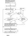
- FIG. 4shows an example flowchart of an embodiment of the steps of fault tolerance in a intelligent virtual server according to the present invention.
- FIG. 5shows another example block diagram of the intelligent virtual server of FIG. 1A with a more details of the distribution control.
- FIG. 1Ashows a simplified block diagram of a distributed intelligent virtual server ( 10 ) according to this present invention.
- the distributed virtual server ( 10 )comprises one or more server units ( 12 ) connected to a distribution control station ( 14 ) via one or more switches or routers ( 16 ).
- One or more client devicese.g., personal computers ( 18 ) are connected to the distribution control station ( 14 ) via a communication network ( 17 ).
- Each server unit ( 12 )stores data ( 13 ) for accessing by clients ( 18 ), wherein the distribution control station ( 14 ) maintain a list ( 15 ) ( FIG. 2B ) of information ( 13 ) from each sever units ( 12 ).
- the distribution control station ( 14 )hosts a virtual block data server (SAN) Web site to perform administration tasks and distribute client's disk volumes requests to specific server units ( 12 ) up to the maximum concurrent client volume requests that each block data server unit ( 12 ) can handle.
- SANvirtual block data server
- the distribution control station ( 14 )maintains a list ( 15 ) of information ( 13 ) from each SAN units ( 12 ), which will be the list of volumes with specific type, size, address of the block data as well as the IP address of each block data server units.
- the distribution control station ( 14 )hosts a virtual video server Web site to perform administration tasks and distribute client's video requests to specific video server units ( 12 ) up to the maximum concurrent client video requests that each video server unit ( 12 ) can handle.
- the distribution control station ( 14 )maintains a list ( 15 ) of video files information ( 13 ) from each server units ( 12 ).
- a server unit ( 12 )comprises a system including one or more storage media such as disk drives ( 25 ), and network interface ( 23 ) such as Gigabits or 100 BT Ethernet card for user access to storage media ( 25 ).
- a server unit ( 12 )also contains a simplified and dedicated computer system, which including processor ( 27 ) and memory ( 28 ) to provide specialized services such as e.g. used for file server, email server, or Web server. Due to its simplicity and specialized operating system ( 30 ) environment that provides specialized service, a server unit ( 12 ) can provide users a more efficient and affective way to access data than a typical computer system.
- the service software modules ( 26 )provide the dedicated service and deliver data streams to client ( 18 ).
- the software service modules ( 26 )also provide server unit ( 12 ) configuration information to distribution control station ( 14 ).
- the network infrastructure ( 17 )can comprise e.g. the Internet or LAN/WAN (Local Area Network/Wide Area Network) infrastructure between the clients ( 18 ) and the virtual server system ( 10 ).
- LAN/WANLocal Area Network/Wide Area Network
- a client system ( 18 ) located in Franceis connected to the virtual server ( 10 ) in U.S.A. by a LAN/WAN network infrastructure ( 17 ) (e.g., Internet).
- the distribution control station ( 14 )upon receiving requests for data volume from clients ( 18 ), maps a fixed number of clients ( 18 ) to each specific server units ( 12 ) and allows each server units ( 12 ) to deliver data streams directly to the corresponding group of clients ( 18 ).
- the server units ( 12 )are clustered together by switches or routers ( 16 ). Each server units ( 12 ) runs independently and as such there is no need for communication between the server units ( 12 ).
- the distributed virtual block data server (SAN) ( 10 )provides a virtual data volume pool ( 15 ) ( FIG. 2B ) for several host clients.
- the distribution control station ( 14 )collects reservations of up to 1000 Tera Bytes of data pool from each individual block data server units (SAN boxes) ( 12 ).
- Each server units ( 12 )can provide multiple data volumes to multiple clients ( 18 ).
- the distribution control station ( 14 )assigns maximum number of clients ( 18 ) to each server units ( 12 ) based on the maximum number of data volumes each server units ( 12 ) can deliver.
- the distribution control station ( 14 )can dynamically add more server units ( 12 ) under its control if client ( 18 ) requests for data volume exceeded 1000 Tera Bytes of data limit in pool due to all volumes have be assigned to other client ( 18 ).
- FIG. 2Ashows a layered software infrastructure.
- the client ( 18 )initially accesses the virtual server ( 10 ) through client interface modules ( 22 ) on distribution control station ( 14 ).
- the client interface modules ( 22 )send client information to virtual server software module ( 24 ) on distribution station ( 14 ).
- the virtual server software module ( 24 )get mapping information for all server units ( 12 ) in virtual server ( 10 ) via network and communicating to the server service software modules ( 26 ) on server unit ( 12 ).
- the virtual server software module ( 24 )selects and provides mapping information of a specific server unit ( 12 ) to client interface modules ( 22 ).
- the client interface modules ( 22 )sends the mapping information to client ( 18 ).
- the client ( 18 )then establishes the communication channel directly to a specific server unit ( 12 ) within virtual server ( 10 ).
- the server units ( 12 )consists dedicated server service software module ( 26 ) ( FIG. 1B ) to provide the required service and deliver the data streams to client ( 18 ).
- server service software module ( 26 )FIG. 1B
- FIG. 2Bshows an example data flow diagram between the distributed virtual server ( 10 ) and the clients ( 18 ), wherein data flow is shown in dashed lines.
- the virtual server ( 10 )includes client interface modules ( 22 ) on distribution control station ( 14 ) which accepts requests from clients ( 18 ) via Web and passes client requests to a virtual server module ( 24 ) on distribution control station ( 14 ).
- the software virtual server module ( 24 ) in the distribution control station ( 14 )monitors status of one or more server units ( 12 ) and selectively provides mapping between each requesting client ( 18 ) to a server unit ( 12 ).
- a server service module ( 26 ) in each server units ( 12 )provides service for delivering served data from/to the server unit ( 12 ) through the network by the requested client ( 18 ) (e.g., streaming, or block data)
- Each server unit ( 12 )can provide essentially the same data stream rate (throughput) to the assigned clients ( 12 ).
- Each thread, which handling client request in the server unit ( 12 )can share equal amount of data bandwidth provided by the server unit ( 12 ) as other threads, which handling similar client requests in that server unit ( 12 ).
- Suitable server unitssuch as NAS, SAN, or PC and computers ( 12 ) for use in the present invention provide concurrent data streams.
- server units ( 12 )can be used in e.g. supporting applications such as providing block data to host system, providing video or audio application of online movie theatre, online educational training class, video on demand (VoD) etc. to end users on client ( 18 ).
- applicationssuch as providing block data to host system, providing video or audio application of online movie theatre, online educational training class, video on demand (VoD) etc. to end users on client ( 18 ).
- a single block data server ( 12 )may have 800 Gbyets of capacity, which may be suitable for host's needs.
- a network attached storage ( 12 )may require 300 GB volume to host 200 hours 3 Mbits/sec movie etc.
- the distribution control station ( 14 )“hides” the server units ( 12 ) from the clients ( 18 ), whereby the clients interface to the distribution control station ( 14 ) and are transparently and selectively provided with requested data service streams from the multiple server units ( 12 ).
- the clients ( 18 )access only one point, the distribution control station ( 14 ), and based on client requests the distribution control station ( 14 ) selectively assigns different server units ( 12 ) to different clients ( 18 ).
- the distribution control station ( 14 )maintains a list ( 15 ) of data information ( 13 ) such as volumes information or video contents stored on each server units ( 12 ), and selectively provide the information of a appropriate server unit to a client ( 18 ).
- the clients ( 18 )communicate with the distribution control station ( 14 ), and the distribution control station maps clients to appropriate server unit ( 12 ) (via the switches/routers), wherein each server unit ( 12 ) provides data streams to one or more mapped clients ( 18 ) independent of other server units ( 12 ) (e.g., FIG. 2B ).
- the distribution control station ( 14 )can be exposed to the clients ( 18 ) through a Web browse. As such, the distribution control station ( 14 ) provides infrastructure to organize all server units ( 12 ) to form a distributed virtual server ( 10 ).
- FIGS. 3-4example flowcharts of an embodiment of the steps of content delivery according to the present invention is shown.
- the distribution control station ( 14 )is configured to perform said steps.
- the server units ( 12 )are interconnected to the distribution control station ( 14 ), and data are stored in each server units ( 12 ) (step 30 ).
- Each server units ( 12 ) that comes on lineis detected (step 32 ), and identification information for the server unit (e.g., IP address) is obtained and entered into the server unit list ( 15 ) (step 34 ).
- identification information for the server unite.g., IP address
- step 34If data information for an server unit ( 12 ) is not in the server unit list (step 36 ), then an information request is sent to the server unit ( 12 ) for data information (step 38 ).
- the data information received from each server units ( 12 )is stored in the server unit list ( 15 ) on distribution control station for the corresponding server unit ( 12 ) (step 40 ). Further, if new data information is added to a server unit ( 10 ), the server unit list ( 15 ) on distribution station ( 14 ) is updated accordingly (step 42 ).
- the server unit list ( 15 ) on distribution control station ( 14 )is checked for the requested data (step 46 ). If a server unit ( 12 ) with the requested data is not found, the client ( 18 ) is informed that the requested data is currently unavailable (step 48 ). Otherwise, if such a server unit ( 12 ) is found (step 50 ), it is optionally determined if the found server unit ( 12 ) is faulty (step 52 ). If so, fault handling is performed (described further below), otherwise, the requesting client ( 18 ) is mapped to the found server unit, and the server unit streams the requested data directly to that client ( 18 ) (step 54 ).
- datae.g., video content, or specific size of volume
- the distribution control station ( 14 )maintains the server unit list ( 15 ), a list of server units ( 12 ), list of data information on each server unit ( 12 ), and list of clients currently mapped/assigned to each server units ( 12 ) for streaming (step 56 ).
- the requestis continually assigned to that identified server unit, and client identification added to the client list for that server unit ( 12 ) (step 70 ). Otherwise, either the request is rejected, or optionally after a time period the ability of said identified server unit ( 12 ) is checked to assign the request to (step 72 ). As described hereinbelow, the assigned server unit ( 12 ) can optionally authenticate the client before providing the requested data information via a data stream (step 74 ). Further, optionally, after a server unit ( 12 ) finishes streaming to a client ( 18 ), the client is removed from the server unit list ( 15 ) as assigned to that server unit (step 76 ).
- each server units ( 12 )authenticates a token from a client ( 18 ) assigned to that server unit ( 12 ).
- the tokenis the IP address of the client ( 18 ), but it can be any other unique identifying information, which provide by distribution control station ( 14 ) to server unit ( 12 ) after receiving client ( 18 ) request.
- the distribution control station ( 14 )optionally sends back to that client ( 18 ) a token (a ticket) indicating which server unit ( 12 ) the distribution control station ( 14 ) has mapped/assigned the client ( 18 ) to for receiving streaming data information from the assigned server unit ( 12 ).
- the distribution control station ( 14 )also send a token to server unit ( 12 ) to indicate which client can be authorized to that server unit ( 12 ).
- each server unit ( 12 )upon communication with the assigned client ( 18 ), each server unit ( 12 ) receives a token from that client ( 18 ), and authenticates by using authentication information previously provided to the server unit ( 12 ) by the distribution control station ( 14 ) as to the identity of that client ( 18 ).
- each assigned client ( 18 )automatically starts to retrieve data stream based on the token received.
- Each server units ( 12 )authenticates the assigned client ( 18 ) based on the information received from distribution control station ( 14 ), and delivers data streams directly to the client ( 18 ) upon authentication.
- the distributed virtual server ( 10 )can further provide fault handling.
- Each individual server units ( 12 ), including several disk drives ( 25 ),can be configured with e.g. RAID1 or RAID5 etc. This provides data protection at the disk level in each server units, against fault of a single disk.
- one or more spare server units ( 12 )may store same data information as one or more servers units ( 12 ), whereby the virtual server ( 10 ) provides server unit's fault handling (e.g. due to a server unit network fault or a IO control card fault, or other).
- the distribution control station ( 14 )monitors all server units ( 12 ) operations (step 80 ), and upon detecting an server unit failure (step 82 ), determines the data information provided to clients mapped to the faulty/failed server unit (step 84 ), utilizes a spare server unit ( 12 ) that includes the same data information (step 86 ) to take the assigned workload off a faulty server unit ( 12 ) and provide data information to the client assigned to the faulty server unit (step 88 ).
- the ratio between the number of spare server units ( 12 ) and the total number of server units ( 12 )is selected based on cost and level of fault tolerance desired.
- a distributed virtual server ( 10 )is scalable by dynamically adding or removing server units ( 12 ) without stop the normal virtual server's ( 10 ) operation depending on data bandwidth, data rate and data throughput requirements. This allows the virtual server ( 10 ) to support a wide range of needs and clients ( 18 ) from small to large, and provide a scalable distributed virtual server for virtually unlimited number data streams.
- Each server units ( 12 )uses a network interface for communication with the distribution control station ( 14 ) and the clients ( 18 ) via a communication network ( 17 ).
- An exampleis IP/Ethernet connection, wherein the IP switches/routers ( 16 ) are used to deliver the data streams from the server units ( 12 ) to clients ( 18 ) such as personal computers via the Internet (IP Internet connection).
- IP Internet connectionIP Internet connection
- Other suitable connectioninclude e.g. Ethernet to ADSL router to deliver the data stream from server units ( 12 ) to TV units with a set Top box via e.g. cable.
- Other network interfacessuch Fiber optical interface for Fiber Channel are possible and contemplated by the present invention.
- the number of server units ( 12 ) and switches/routers ( 16 )depends on the bandwidth required of the virtual server ( 10 ). For example, in a switch ( 16 ) connected to a 1-Gitabit Internet port for client connection, and to eight or twelve 100-bit of server unit ports, each server units ( 12 ) is configured with 100-bits/sec Ethernet card. A data transfer forwarder sends information to the corresponding 100-bits port for each server units ( 12 ).
- the number and type of switches ( 16 )further depends on the number of server units ( 12 ) connected to each switch ( 16 ), and data streaming bandwidth and rate requirements.
- the example switches or routersare manufactured by CiscoTM and 3 ComTM.
- server units ( 12 )are used scalably to efficiently deliver data streams to clients ( 18 ), under the control of one (or more for fault handling) distribution controls station ( 14 ) that preferably provide a single point of contact/interface to the clients ( 18 ) via the network ( 17 ). As more bandwidth and data streams are required, more server units ( 12 ) and routers/switches ( 17 ) are added to the virtual server ( 10 ) to deliver more data streams. Because each server unit ( 12 ) operates independent of other server units ( 12 ) without sharing internal resources, there is no resource contention in a virtual server ( 10 ) according to the present invention that exists in conventional servers such as those utilizing SMP, or MPP machines.
- each individual server unit ( 12 ) in a virtual server ( 10 )has no geometric restriction each individual server unit ( 12 ) can be placed in a single rack mounted cabinet or in a room, or cross the region or continental. This allows saving network bandwidth effectively.
- the per data stream priceis low, specially for delivering a large number of streams to end users when using low cost NAS.
- the distributed virtual serverhas more independently operated network cards and 10 cards, therefore, in case of a single card broken will not bring the entire virtual server malfunction, instead, majority part of the virtual server can still operating normally. Besides, the automatic fault handling can be provided.
- FIG. 5shows a more detailed block diagram of the virtual server ( 10 ) of FIG. 1A , connected to client ( 18 ) via the network ( 17 ).
- the distribution control station ( 14 )can comprise a computer system with computation and communication capacity depending on the number of data streams requests it can handle.
- Such a computer systemis configured software to assigns/map clients ( 18 ) and server units ( 12 ) as described herein, whereby each server units ( 12 ) transparently delivers a data stream to an assigned/corresponding client ( 18 ).
- Web server technologyprovides data streaming link between each server units ( 12 ) and corresponding client ( 18 ).
- the distribution control station ( 14 )comprises a computer system which includes a bus ( 102 ) or other communication mechanism for communicating information, and a processor (CPU) ( 104 ) coupled with the bus ( 102 ) for processing information.
- the computer system ( 14 )also includes a main memory ( 106 ), such as a random access memory (RAM) or other dynamic storage device, coupled to the bus ( 102 ) for storing information and program instructions to be executed by the processor ( 104 ).
- the main memory ( 106 )also may be used for storing temporary variables or other intermediate information during execution or instructions to be executed by the processor ( 104 ).
- the computer system ( 14 )further includes a read only memory (ROM) ( 108 ) or other static storage device coupled to the bus ( 102 ) for storing static information and instructions for the processor ( 104 ).
- the bus ( 102 )may contain, for example, thirty-two address lines for addressing video memory or main memory ( 106 ).
- the bus ( 102 )can also include, for example, a 32-bit data bus for transferring data between and among the components, such as the CPU 104 , the main memory 106 , video memory and the storage media ( 110 ). Alternatively, multiplex data/address lines may be used instead of separate data and address lines.
- the CPU ( 104 )comprises a microprocessor manufactured by Motorola®, such as the 680 ⁇ 0 processor or a microprocessor manufactured by Intel®, such as the 80 ⁇ 86, or Pentium® processor, or a SPARC® microprocessor from Sun Microsystems®.
- the main memory ( 106 )can comprise dynamic random access memory (DRAM).
- video memory(not shown) can comprise a dual-ported video random access memory.
- the computer system ( 14 )may be coupled via the bus ( 102 ) to a display ( 112 ), such as a cathode ray tube (CRT), for displaying information to a computer user.
- a displaysuch as a cathode ray tube (CRT)
- An input device ( 114 )is coupled to the bus ( 102 ) for communicating information and command selections to the processor ( 104 ).
- cursor control116
- cursor controlsuch as a mousse, a trackball, or cursor direction keys
- This input devicetypically has two degrees of freedom in two axes, a first axis (e.g., x) and a second axis (e.g., y) that allows the device to specify positions in a plane.
- the steps of the processes of the present inventionis provided by computer systems ( 14 ) in response to the processor ( 104 ) executing one or more sequences of one or more instructions contained in the main memory ( 106 ).
- Such instructionsmay be read into the main memory ( 106 ) from another computer-readable medium, such as the storage device ( 110 ).
- Execution of the sequences of instructions contained in the main memory ( 106 )causes the processor ( 104 ) to perform the process steps described herein.
- processors in a multi-processing arrangementmay also be employed to execute the sequences of instructions contained in the main memory ( 106 ).
- hard-wired circuitrysuch as Application Specific Integrated Circuit (ASIC) may be used in place of or in combination with software instructions to implement the invention.
- ASICApplication Specific Integrated Circuit
- Non-volatile mediaincludes, for example, optical or magnetic disks, such as the storage device ( 110 ).
- Volatile mediaincludes dynamic memory, such as the main memory ( 106 ).
- Transmission mediaincludes coaxial cables, copper wire and fiber optics, including the wires that comprise the bus ( 102 ). Transmission media can also take the form of acoustic or light waves, such as those generated during radio wave and infrared data communications.
- Computer-readable mediainclude, for example, a floppy disk, a flexible disk, hard disk, magnetic tape, or any other magnetic medium, a CD-ROM, any other optical medium, punch cards, paper tape, any other physical medium with patterns of holes, a RAM, a PROM, an EPROM, a FLASH-EPROM, any other memory chip or cartridge, a carrier wave as described hereinafter, or any other medium from which a computer can read.
- Various forms of computer readable mediamay be involved in carrying one or more sequences of one or more instructions to the processor ( 104 ) for execution.
- the instructionsmay initially be carried on a magnetic disk of a remote computer.
- the remote computercan load the instructions into its dynamic memory and send the instructions over a telephone line using a modem.
- a modem local to the computer system ( 14 )can receive the data on the telephone line and use an infrared transmitter to convert the data to an infrared signal.
- An infrared detector coupled to the bus ( 102 )can receive the data carried in the infrared signal and place the data on the bus ( 102 ).
- the bus ( 102 )carries the data to the main memory ( 106 ), from which the processor ( 104 ) retrieves and executes the instructions.
- the instructions received from the main memory ( 106 )may optionally be stored on the storage device ( 110 ) either before or after execution by the processor ( 104 ).
- the computer system ( 14 )also includes a communication interface ( 118 ) coupled to bus the ( 102 ).
- the communication interface ( 118 )provides a two-way data communication coupling to a network link ( 120 ) that is connected to routers ( 16 ).
- the communication interface ( 118 )may be an integrated services digital network (ISDN) card or a modern to provide a data communication connection to a corresponding type of telephone line, which can comprise part of the network link ( 120 ).
- the communication interface ( 118 )may be a local area network (LAN) card to provide a data communication connection to a compatible LAN.
- LANlocal area network
- Wireless linksmay also be implemented.
- the communication interface ( 118 )sends and receives electrical electromagnetic or optical signals that carry digital data streams representing various types of information.
- the network link ( 120 )typically provides data communication through one or more networks to other data devices.
- the network link ( 120 )may provide a connection through a local network to a host/server computer or to data equipment operated by an Internet Service Provider (ISP) ( 126 ) via switched ( 16 ).
- the ISP ( 126 )in turn provides data communication services through the world wide packet data communication network now commonly referred to as the “Internet” ( 128 ).
- the Internet ( 128 )uses electrical electromagnetic or optical signals that carry digital data streams.
- the computer system ( 14 )further includes web server ( 11 ) for providing e.g. a user interface to the clients ( 18 ) for requesting data streams from the virtual server ( 10 ).
- said user interfacecan include a list of available video content files in the virtual video server ( 10 ) and ways of selecting content files for viewing, including optionally payment terms.
- the computer system ( 14 )can send messages and receive data, including program code, through the communication interface ( 118 ).
- clients ( 18 )can transmit code (e.g., program instructions, HTML, etc.) for an application program through the Internet ( 128 ), the ISP ( 126 ), and communication interface ( 118 ).
- the example versions of the invention described hereincan be implemented as logical operations in a distribution control station ( 14 ).
- the logical operations of the present inventioncan be implemented as a sequence of steps executing on distribution control station ( 14 ).
- the implementationis a matter of choice and can depend on performance of the distribution control station ( 14 ) implementing the invention.
- the logical operations constituting said example versions of the inventionare referred to for e.g. as operations, steps or modules.
Landscapes
- Engineering & Computer Science (AREA)
- Computer Networks & Wireless Communication (AREA)
- Signal Processing (AREA)
- Computer Hardware Design (AREA)
- General Engineering & Computer Science (AREA)
- Computer Security & Cryptography (AREA)
- Information Retrieval, Db Structures And Fs Structures Therefor (AREA)
- Computer And Data Communications (AREA)
Abstract
Description
- Disk Drive: Provide computer host system with block data through special cable access such as IDE or SCSI cable depends on type of disk drive.
- SAN: a storage system comprises multi-disk drives and provides computer host system with block data through Fiber optical for Fiber Channel accessing or Ethernet cable for TCP/IP/UDP accessing.
- NAS: A dedicated storage system, which comprises multiple disk drives and configured to provide specialized services such as file server, Web server, video server etc. to end user system through network media.
b) The Traditional Server: - Currently there are two types of servers on the market one is SMP based and another is MPP based.
- SMP Based Server:
- This type of system has one operating system (OS) running on top of multiple processors (CPU). Each processor may need to compete certain system resources with other processor in order to perform a task. Therefore, It may introduce certain delay for each processor to execute a task.
- MPP Based Server:
- Other conventional servers utilize multi-node massively parallel processor (MPP) machines including a clustering together of processors that do not share resources such as memory (i.e., each CPU has its own memory). Each processor has its own operating system (OS) or part of OS. Though the CPUs do not share common memory, the node may commonly support a distributed file system on top of a group of nodes, wherein the contents are stored on the file system. This requires complex coordination between the nodes through intra-node communication channel. Hence, this will introduce delay in term of task executing by a processor. Even there is MPP clustering system do not support distributed file system, each processor on the system often still support coordinate each other to perform a portion of the task.
- All of these types of servers are very expensive and geometrically limited in a centralized location. In addition, the current the servers on Internet such as Web server, proxy server, and Web cache server are not intelligent enough such that they do not provide automatic fault handling hence they do not have the concept of virtual server.
- The distribution control station will accept requests from clients and assign them to each individual server unit for service. After a client is assigned to a server unit by distribution control station, the server unit will serve the client directly without interference of the distribution control station. Since each server units does not share resources such as memory, system buses, networking card, and IO control card, the throughput will be higher than the conventional SMP and MPP server.
- The virtual server does not limited by the geometry location like SMP or MPP clustering system does. Each individual server units such as NAS, SAN box could be in a place of a rack mounted Cabinet, in a room, or even crossing the different regions and continentals, depending on the business's needs.
- The virtual server is more fault tolerant than the conventional server due to it has more individual operated network card and IO control card on each server units. Therefore, when a fault occurred on an individual network card or IO control card on a server unit, the rest of server units on the virtual server system still can server the majority client requests. In addition, distribution control station can provide the automatic fault handling by replacing a fault server unit with a hot spare server unit for continue operation.
- The capacity of the virtual server can be scale up by dynamically adding more server units without interrupt the operation of the virtual server. The scalability of the virtual server can meet the ever increasing demand from huge number of clients.
- Due to the virtual server unit do not have geometry limit, it can effectively save the network bandwidth. For example, to overcome the network's bandwidth limitation in delivering the video contents by using NAS, each individual NAS can be placed at different network domain, or crossing the regions and continentals. This will allow a single centralized copy of video content be replicated to these limited NAS first and all massive video requests could be distributed to these distributed NAS for video accessing.
- The cost of such virtual server could be lower than the conventional server due to often the off the shelf, lower cost NAS or SAN or other can be used.
Claims (39)
Priority Applications (3)
| Application Number | Priority Date | Filing Date | Title |
|---|---|---|---|
| US10/116,511US7734778B2 (en) | 2002-04-05 | 2002-04-05 | Distributed intelligent virtual server |
| US12/487,976US20100242099A1 (en) | 2002-04-05 | 2009-06-19 | Method and apparatus of UI design for web-based computer user working environment |
| US12/756,412US8645542B2 (en) | 2002-04-05 | 2010-04-08 | Distributed intelligent virtual server |
Applications Claiming Priority (1)
| Application Number | Priority Date | Filing Date | Title |
|---|---|---|---|
| US10/116,511US7734778B2 (en) | 2002-04-05 | 2002-04-05 | Distributed intelligent virtual server |
Related Child Applications (2)
| Application Number | Title | Priority Date | Filing Date |
|---|---|---|---|
| US11/374,302Continuation-In-PartUS7945652B2 (en) | 2002-04-05 | 2004-07-02 | Display multi-layers list item in web-browser with supporting of concurrent multi-users |
| US12/756,412ContinuationUS8645542B2 (en) | 2002-04-05 | 2010-04-08 | Distributed intelligent virtual server |
Publications (2)
| Publication Number | Publication Date |
|---|---|
| US20030191838A1 US20030191838A1 (en) | 2003-10-09 |
| US7734778B2true US7734778B2 (en) | 2010-06-08 |
Family
ID=28673998
Family Applications (2)
| Application Number | Title | Priority Date | Filing Date |
|---|---|---|---|
| US10/116,511Expired - Fee RelatedUS7734778B2 (en) | 2002-04-05 | 2002-04-05 | Distributed intelligent virtual server |
| US12/756,412Expired - Fee RelatedUS8645542B2 (en) | 2002-04-05 | 2010-04-08 | Distributed intelligent virtual server |
Family Applications After (1)
| Application Number | Title | Priority Date | Filing Date |
|---|---|---|---|
| US12/756,412Expired - Fee RelatedUS8645542B2 (en) | 2002-04-05 | 2010-04-08 | Distributed intelligent virtual server |
Country Status (1)
| Country | Link |
|---|---|
| US (2) | US7734778B2 (en) |
Cited By (5)
| Publication number | Priority date | Publication date | Assignee | Title |
|---|---|---|---|---|
| US20090265361A1 (en)* | 2008-04-17 | 2009-10-22 | Akihisa Nagami | Master management system, master management method, and master management program |
| US20100218014A1 (en)* | 2009-02-26 | 2010-08-26 | Bozek James J | Power Management To Maximize Reduced Power State For Virtual Machine Platforms |
| US20130332583A1 (en)* | 2006-01-09 | 2013-12-12 | Telecommunication Systems, Inc. | Virtual Location Aware Content Using Presence Information Data Formation with Location Object (PIDF-LO) |
| US8825752B1 (en)* | 2012-05-18 | 2014-09-02 | Netapp, Inc. | Systems and methods for providing intelligent automated support capable of self rejuvenation with respect to storage systems |
| CN103686196B (en)* | 2013-12-31 | 2017-03-01 | 北京中科大洋科技发展股份有限公司 | A kind of seamless switch-over system ensureing the normal broadcast of video and audio and method |
Families Citing this family (52)
| Publication number | Priority date | Publication date | Assignee | Title |
|---|---|---|---|---|
| US7165103B2 (en)* | 2002-06-26 | 2007-01-16 | Microsoft Corporation | Method and system for matching network clients and servers under matching constraints |
| US7240365B2 (en)* | 2002-09-13 | 2007-07-03 | Sun Microsystems, Inc. | Repositing for digital content access control |
| US20040054629A1 (en)* | 2002-09-13 | 2004-03-18 | Sun Microsystems, Inc., A Delaware Corporation | Provisioning for digital content access control |
| US7398557B2 (en) | 2002-09-13 | 2008-07-08 | Sun Microsystems, Inc. | Accessing in a rights locker system for digital content access control |
| US7512972B2 (en) | 2002-09-13 | 2009-03-31 | Sun Microsystems, Inc. | Synchronizing for digital content access control |
| US20040059939A1 (en)* | 2002-09-13 | 2004-03-25 | Sun Microsystems, Inc., A Delaware Corporation | Controlled delivery of digital content in a system for digital content access control |
| US7380280B2 (en)* | 2002-09-13 | 2008-05-27 | Sun Microsystems, Inc. | Rights locker for digital content access control |
| US20040083370A1 (en)* | 2002-09-13 | 2004-04-29 | Sun Microsystems, Inc., A Delaware Corporation | Rights maintenance in a rights locker system for digital content access control |
| US20040059913A1 (en)* | 2002-09-13 | 2004-03-25 | Sun Microsystems, Inc., A Delaware Corporation | Accessing for controlled delivery of digital content in a system for digital content access control |
| US7913312B2 (en)* | 2002-09-13 | 2011-03-22 | Oracle America, Inc. | Embedded content requests in a rights locker system for digital content access control |
| WO2005008448A2 (en)* | 2003-07-18 | 2005-01-27 | Remote Meeting Technologies, Inc. | Browser-based video meeting system |
| US7243089B2 (en)* | 2003-11-25 | 2007-07-10 | International Business Machines Corporation | System, method, and service for federating and optionally migrating a local file system into a distributed file system while preserving local access to existing data |
| US8583770B2 (en)* | 2005-02-16 | 2013-11-12 | Red Hat, Inc. | System and method for creating and managing virtual services |
| US20060190532A1 (en)* | 2005-02-23 | 2006-08-24 | Kalyana Chadalavada | Apparatus and methods for multiple user remote connections to an information handling system via a remote access controller |
| US20070204266A1 (en)* | 2006-02-28 | 2007-08-30 | International Business Machines Corporation | Systems and methods for dynamically managing virtual machines |
| US20080016192A1 (en)* | 2006-07-13 | 2008-01-17 | International Business Machines Corporation | System and Method for Performing an Administrative Task upon the Occurrence of a Triggering Event |
| US8312120B2 (en)* | 2006-08-22 | 2012-11-13 | Citrix Systems, Inc. | Systems and methods for providing dynamic spillover of virtual servers based on bandwidth |
| US8493858B2 (en)* | 2006-08-22 | 2013-07-23 | Citrix Systems, Inc | Systems and methods for providing dynamic connection spillover among virtual servers |
| US20090144130A1 (en)* | 2007-07-13 | 2009-06-04 | Grouf Nicholas A | Methods and systems for predicting future data |
| US8959516B2 (en) | 2007-07-30 | 2015-02-17 | International Business Machines Corporation | Methods and systems for coordinated financial transactions in distributed and parallel environments |
| WO2010002407A1 (en)* | 2008-07-02 | 2010-01-07 | Hewlett-Packard Development Company, L.P. | Performing administrative tasks associated with a network-attached storage system at a client |
| US20100031253A1 (en)* | 2008-07-29 | 2010-02-04 | Electronic Data Systems Corporation | System and method for a virtualization infrastructure management environment |
| US9910708B2 (en)* | 2008-08-28 | 2018-03-06 | Red Hat, Inc. | Promotion of calculations to cloud-based computation resources |
| US20110153751A1 (en)* | 2009-12-18 | 2011-06-23 | David Rice | Content management systems and methods |
| US8265973B2 (en) | 2010-03-11 | 2012-09-11 | International Business Machines Corporation | Analytic-based scaling of information technology resources |
| US9342368B2 (en) | 2010-08-31 | 2016-05-17 | International Business Machines Corporation | Modular cloud computing system |
| US9003014B2 (en) | 2010-08-31 | 2015-04-07 | International Business Machines Corporation | Modular cloud dynamic application assignment |
| KR20120101609A (en)* | 2011-03-04 | 2012-09-14 | 삼성전자주식회사 | Server, system and method for offering distributed service |
| GB2489915A (en)* | 2011-04-04 | 2012-10-17 | Intragen Ltd | Management system for processing data |
| US8914478B2 (en)* | 2011-05-19 | 2014-12-16 | International Business Machines Corporation | Automated deployment of software for managed hardware in a storage area network |
| US9191355B2 (en)* | 2011-09-12 | 2015-11-17 | Crytek Gmbh | Computer-implemented method for posting messages about future events to users of a social network, computer system and computer-readable medium thereof |
| US9001696B2 (en) | 2011-12-01 | 2015-04-07 | International Business Machines Corporation | Distributed dynamic virtual machine configuration service |
| US10282221B2 (en)* | 2011-12-09 | 2019-05-07 | International Business Machines Corporation | Controlling usage of virtual disks before their attachment to virtual machines |
| US8863141B2 (en) | 2011-12-14 | 2014-10-14 | International Business Machines Corporation | Estimating migration costs for migrating logical partitions within a virtualized computing environment based on a migration cost history |
| US8694995B2 (en) | 2011-12-14 | 2014-04-08 | International Business Machines Corporation | Application initiated negotiations for resources meeting a performance parameter in a virtualized computing environment |
| US9229901B1 (en) | 2012-06-08 | 2016-01-05 | Google Inc. | Single-sided distributed storage system |
| US8825851B2 (en)* | 2012-08-17 | 2014-09-02 | Vmware, Inc. | Management of a virtual machine in a storage area network environment |
| US9058122B1 (en) | 2012-08-30 | 2015-06-16 | Google Inc. | Controlling access in a single-sided distributed storage system |
| US8862561B1 (en) | 2012-08-30 | 2014-10-14 | Google Inc. | Detecting read/write conflicts |
| US8676851B1 (en) | 2012-08-30 | 2014-03-18 | Google Inc. | Executing transactions in distributed storage systems |
| US9164702B1 (en) | 2012-09-07 | 2015-10-20 | Google Inc. | Single-sided distributed cache system |
| US8924443B2 (en)* | 2012-10-05 | 2014-12-30 | Gary Robin Maze | Document management systems and methods |
| US9049265B1 (en) | 2012-12-26 | 2015-06-02 | Google Inc. | Serving remote access to storage resources |
| CN103401938B (en)* | 2013-08-07 | 2016-11-09 | 西安电子科技大学 | Resource allocation system and method based on business characteristics under distributed cloud architecture |
| US9313274B2 (en) | 2013-09-05 | 2016-04-12 | Google Inc. | Isolating clients of distributed storage systems |
| US20150100670A1 (en)* | 2013-10-04 | 2015-04-09 | International Business Machines Corporation | Transporting multi-destination networking traffic by sending repetitive unicast |
| WO2016182587A1 (en)* | 2015-05-08 | 2016-11-17 | Hewlett Packard Enterprise Development Lp | Heterogeneous hot spare server pool |
| US10911225B2 (en)* | 2015-06-05 | 2021-02-02 | Nutanix, Inc. | Optimizable full-path encryption in a virtualization environment |
| CN106330986B (en)* | 2015-06-15 | 2020-11-20 | 中兴通讯股份有限公司 | Message transmission method and device |
| US11272005B1 (en)* | 2018-09-25 | 2022-03-08 | Amazon Technologies, Inc. | Communicating state information in a distributed storage environment |
| WO2020227985A1 (en)* | 2019-05-15 | 2020-11-19 | Alibaba Group Holding Limited | Real-time fault detection on network devices and circuits based on traffic volume statistics |
| CN112835537A (en)* | 2021-03-12 | 2021-05-25 | 东莞中国科学院云计算产业技术创新与育成中心 | Distributed data access method, apparatus and computer equipment |
Citations (9)
| Publication number | Priority date | Publication date | Assignee | Title |
|---|---|---|---|---|
| US6108703A (en)* | 1998-07-14 | 2000-08-22 | Massachusetts Institute Of Technology | Global hosting system |
| US20010052016A1 (en)* | 1999-12-13 | 2001-12-13 | Skene Bryan D. | Method and system for balancing load distrubution on a wide area network |
| US6449647B1 (en)* | 1997-08-01 | 2002-09-10 | Cisco Systems, Inc. | Content-aware switching of network packets |
| US6654807B2 (en)* | 1998-02-10 | 2003-11-25 | Cable & Wireless Internet Services, Inc. | Internet content delivery network |
| US6816905B1 (en)* | 2000-11-10 | 2004-11-09 | Galactic Computing Corporation Bvi/Bc | Method and system for providing dynamic hosted service management across disparate accounts/sites |
| US6857012B2 (en)* | 2000-10-26 | 2005-02-15 | Intel Corporation | Method and apparatus for initializing a new node in a network |
| US7047300B1 (en)* | 1998-02-10 | 2006-05-16 | Sprint Communications Company L.P. | Survivable and scalable data system and method for computer networks |
| US7068597B1 (en)* | 2000-11-27 | 2006-06-27 | 3Com Corporation | System and method for automatic load balancing in a data-over-cable network |
| US7225464B2 (en)* | 2002-04-03 | 2007-05-29 | Yodlee.Com, Inc. | Method for verifying the identity of a user for session authentication purposes during Web navigation |
Family Cites Families (6)
| Publication number | Priority date | Publication date | Assignee | Title |
|---|---|---|---|---|
| US6408336B1 (en) | 1997-03-10 | 2002-06-18 | David S. Schneider | Distributed administration of access to information |
| US6664987B1 (en) | 1997-11-17 | 2003-12-16 | International Business Machines Corporation | System for displaying a computer managed network layout with transient display of user selected attributes of displayed network objects |
| US6690400B1 (en) | 1999-09-29 | 2004-02-10 | Flash Vos, Inc. | Graphic user interface for resources management of super operating system based computers |
| US6490619B1 (en) | 1999-12-07 | 2002-12-03 | International Business Machines Corporation | Method and system for managing multiple lightweight directory access protocol directory servers |
| US7082521B1 (en) | 2000-08-24 | 2006-07-25 | Veritas Operating Corporation | User interface for dynamic computing environment using allocateable resources |
| US6971101B1 (en) | 2000-09-12 | 2005-11-29 | Motorola, Inc. | Managing asynchronous requests for user interface resources in an information system |
- 2002
- 2002-04-05USUS10/116,511patent/US7734778B2/ennot_activeExpired - Fee Related
- 2010
- 2010-04-08USUS12/756,412patent/US8645542B2/ennot_activeExpired - Fee Related
Patent Citations (9)
| Publication number | Priority date | Publication date | Assignee | Title |
|---|---|---|---|---|
| US6449647B1 (en)* | 1997-08-01 | 2002-09-10 | Cisco Systems, Inc. | Content-aware switching of network packets |
| US6654807B2 (en)* | 1998-02-10 | 2003-11-25 | Cable & Wireless Internet Services, Inc. | Internet content delivery network |
| US7047300B1 (en)* | 1998-02-10 | 2006-05-16 | Sprint Communications Company L.P. | Survivable and scalable data system and method for computer networks |
| US6108703A (en)* | 1998-07-14 | 2000-08-22 | Massachusetts Institute Of Technology | Global hosting system |
| US20010052016A1 (en)* | 1999-12-13 | 2001-12-13 | Skene Bryan D. | Method and system for balancing load distrubution on a wide area network |
| US6857012B2 (en)* | 2000-10-26 | 2005-02-15 | Intel Corporation | Method and apparatus for initializing a new node in a network |
| US6816905B1 (en)* | 2000-11-10 | 2004-11-09 | Galactic Computing Corporation Bvi/Bc | Method and system for providing dynamic hosted service management across disparate accounts/sites |
| US7068597B1 (en)* | 2000-11-27 | 2006-06-27 | 3Com Corporation | System and method for automatic load balancing in a data-over-cable network |
| US7225464B2 (en)* | 2002-04-03 | 2007-05-29 | Yodlee.Com, Inc. | Method for verifying the identity of a user for session authentication purposes during Web navigation |
Cited By (8)
| Publication number | Priority date | Publication date | Assignee | Title |
|---|---|---|---|---|
| US20130332583A1 (en)* | 2006-01-09 | 2013-12-12 | Telecommunication Systems, Inc. | Virtual Location Aware Content Using Presence Information Data Formation with Location Object (PIDF-LO) |
| US9148491B2 (en)* | 2006-01-09 | 2015-09-29 | Telecommunication Systems, Inc. | Virtual location aware content using presence information data formation with location object (PIDF-LO) |
| US20090265361A1 (en)* | 2008-04-17 | 2009-10-22 | Akihisa Nagami | Master management system, master management method, and master management program |
| US7917533B2 (en)* | 2008-04-17 | 2011-03-29 | Hitachi, Ltd. | Master management system, master management method, and master management program |
| US20100218014A1 (en)* | 2009-02-26 | 2010-08-26 | Bozek James J | Power Management To Maximize Reduced Power State For Virtual Machine Platforms |
| US8327169B2 (en)* | 2009-02-26 | 2012-12-04 | International Business Machines Corporation | Power management to maximize reduced power state for virtual machine platforms |
| US8825752B1 (en)* | 2012-05-18 | 2014-09-02 | Netapp, Inc. | Systems and methods for providing intelligent automated support capable of self rejuvenation with respect to storage systems |
| CN103686196B (en)* | 2013-12-31 | 2017-03-01 | 北京中科大洋科技发展股份有限公司 | A kind of seamless switch-over system ensureing the normal broadcast of video and audio and method |
Also Published As
| Publication number | Publication date |
|---|---|
| US20110093740A1 (en) | 2011-04-21 |
| US20030191838A1 (en) | 2003-10-09 |
| US8645542B2 (en) | 2014-02-04 |
Similar Documents
| Publication | Publication Date | Title |
|---|---|---|
| US7734778B2 (en) | Distributed intelligent virtual server | |
| US20030079016A1 (en) | Using NAS appliance to build a non-conventional distributed video server | |
| US7562110B2 (en) | File switch and switched file system | |
| CN104011701B (en) | Content delivery network system and method operable in a content delivery network | |
| US10992739B2 (en) | Integrated application-aware load balancer incorporated within a distributed-service-application-controlled distributed computer system | |
| US7222150B1 (en) | Network server card and method for handling requests received via a network interface | |
| CN101460907B (en) | Systems and methods for managing execution of programs | |
| US6922727B2 (en) | Method and system for managing parallel data transfer through multiple sockets to provide scalability to a computer network | |
| US6718392B1 (en) | Queue pair partitioning in distributed computer system | |
| US7962609B2 (en) | Adaptive storage block data distribution | |
| US7103626B1 (en) | Partitioning in distributed computer system | |
| US6597956B1 (en) | Method and apparatus for controlling an extensible computing system | |
| US20080222267A1 (en) | Method and system for web cluster server | |
| US7401114B1 (en) | Method and apparatus for making a computational service highly available | |
| EP1908251A1 (en) | Method and system for dynamically rebalancing client sessions within a cluster of servers connected to a network | |
| JP2006510976A5 (en) | ||
| US7895264B2 (en) | Storage cluster server network | |
| CN108063813A (en) | The method and system of cryptographic service network parallelization under a kind of cluster environment | |
| US20040093390A1 (en) | Connected memory management | |
| US7627650B2 (en) | Short-cut response for distributed services | |
| JP4864210B2 (en) | Work group server implementation method and apparatus | |
| WO2001063402A2 (en) | Method and apparatus for making a computational service highly available | |
| KR20020021415A (en) | Method for Internet Broadcast-Purpose Audio/Video Streaming Accelerator and Its System | |
| CN115174361A (en) | Information transmission method, system and device based on authentication gateway | |
| CN117785459A (en) | A control system for load balancing method |
Legal Events
| Date | Code | Title | Description |
|---|---|---|---|
| AS | Assignment | Owner name:TSAO, SHENG (TED) TAI, CALIFORNIA Free format text:ASSIGNMENT OF ASSIGNORS INTEREST;ASSIGNOR:TSAO, SHENG (TED) TAI;REEL/FRAME:013459/0414 Effective date:20020322 Owner name:TSAO, SHENG (TED) TAI,CALIFORNIA Free format text:ASSIGNMENT OF ASSIGNORS INTEREST;ASSIGNOR:TSAO, SHENG (TED) TAI;REEL/FRAME:013459/0414 Effective date:20020322 | |
| AS | Assignment | Owner name:RPX CORPORATION, CALIFORNIA Free format text:LICENSE;ASSIGNOR:TSAO, SHENG TAI (TED);REEL/FRAME:025053/0669 Effective date:20100928 | |
| AS | Assignment | Owner name:RPX CORPORATION, CALIFORNIA Free format text:ASSIGNMENT OF ASSIGNORS INTEREST;ASSIGNOR:TSAO, SHENG TAI;REEL/FRAME:025161/0511 Effective date:20100928 | |
| FEPP | Fee payment procedure | Free format text:PAT HOLDER NO LONGER CLAIMS SMALL ENTITY STATUS, ENTITY STATUS SET TO UNDISCOUNTED (ORIGINAL EVENT CODE: STOL); ENTITY STATUS OF PATENT OWNER: LARGE ENTITY | |
| FPAY | Fee payment | Year of fee payment:4 | |
| FEPP | Fee payment procedure | Free format text:MAINTENANCE FEE REMINDER MAILED (ORIGINAL EVENT CODE: REM.) | |
| AS | Assignment | Owner name:JEFFERIES FINANCE LLC, NEW YORK Free format text:SECURITY INTEREST;ASSIGNOR:RPX CORPORATION;REEL/FRAME:046486/0433 Effective date:20180619 | |
| LAPS | Lapse for failure to pay maintenance fees | Free format text:PATENT EXPIRED FOR FAILURE TO PAY MAINTENANCE FEES (ORIGINAL EVENT CODE: EXP.) | |
| STCH | Information on status: patent discontinuation | Free format text:PATENT EXPIRED DUE TO NONPAYMENT OF MAINTENANCE FEES UNDER 37 CFR 1.362 | |
| FP | Lapsed due to failure to pay maintenance fee | Effective date:20180608 | |
| AS | Assignment | Owner name:RPX CORPORATION, CALIFORNIA Free format text:RELEASE BY SECURED PARTY;ASSIGNOR:JEFFERIES FINANCE LLC;REEL/FRAME:054486/0422 Effective date:20201023 |