US7734466B2 - Reduced complexity recursive least square lattice structure adaptive filter by means of limited recursion of the backward and forward error prediction squares - Google Patents
Reduced complexity recursive least square lattice structure adaptive filter by means of limited recursion of the backward and forward error prediction squaresDownload PDFInfo
- Publication number
- US7734466B2 US7734466B2US11/399,907US39990706AUS7734466B2US 7734466 B2US7734466 B2US 7734466B2US 39990706 AUS39990706 AUS 39990706AUS 7734466 B2US7734466 B2US 7734466B2
- Authority
- US
- United States
- Prior art keywords
- adaptive filter
- error prediction
- filter
- squares
- backward
- Prior art date
- Legal status (The legal status is an assumption and is not a legal conclusion. Google has not performed a legal analysis and makes no representation as to the accuracy of the status listed.)
- Expired - Fee Related, expires
Links
- 230000003044adaptive effectEffects0.000titleclaimsabstractdescription95
- 230000002829reductive effectEffects0.000titledescription7
- 238000000034methodMethods0.000claimsabstractdescription24
- 230000000670limiting effectEffects0.000claimsdescription4
- 238000001914filtrationMethods0.000claims1
- 238000004891communicationMethods0.000description13
- 238000010586diagramMethods0.000description12
- 230000008569processEffects0.000description11
- 230000003111delayed effectEffects0.000description3
- 230000007246mechanismEffects0.000description3
- 230000003190augmentative effectEffects0.000description2
- 238000004364calculation methodMethods0.000description2
- 230000001413cellular effectEffects0.000description2
- 230000006872improvementEffects0.000description2
- 230000000135prohibitive effectEffects0.000description2
- 230000004044responseEffects0.000description2
- 230000008901benefitEffects0.000description1
- 238000006243chemical reactionMethods0.000description1
- 230000008094contradictory effectEffects0.000description1
- 230000007423decreaseEffects0.000description1
- 230000003247decreasing effectEffects0.000description1
- 230000006870functionEffects0.000description1
- 238000005259measurementMethods0.000description1
- 230000009467reductionEffects0.000description1
Images


Classifications
- H—ELECTRICITY
- H03—ELECTRONIC CIRCUITRY
- H03H—IMPEDANCE NETWORKS, e.g. RESONANT CIRCUITS; RESONATORS
- H03H21/00—Adaptive networks
- H03H21/0012—Digital adaptive filters
- H03H21/0014—Lattice filters
- H—ELECTRICITY
- H03—ELECTRONIC CIRCUITRY
- H03H—IMPEDANCE NETWORKS, e.g. RESONANT CIRCUITS; RESONATORS
- H03H21/00—Adaptive networks
- H03H21/0012—Digital adaptive filters
- H03H21/0043—Adaptive algorithms
- H—ELECTRICITY
- H03—ELECTRONIC CIRCUITRY
- H03H—IMPEDANCE NETWORKS, e.g. RESONANT CIRCUITS; RESONATORS
- H03H21/00—Adaptive networks
- H03H21/0012—Digital adaptive filters
- H03H21/0043—Adaptive algorithms
- H03H2021/0049—Recursive least squares algorithm
- H—ELECTRICITY
- H03—ELECTRONIC CIRCUITRY
- H03H—IMPEDANCE NETWORKS, e.g. RESONANT CIRCUITS; RESONATORS
- H03H21/00—Adaptive networks
- H03H21/0012—Digital adaptive filters
- H03H2021/007—Computation saving measures; Accelerating measures
- H—ELECTRICITY
- H03—ELECTRONIC CIRCUITRY
- H03H—IMPEDANCE NETWORKS, e.g. RESONANT CIRCUITS; RESONATORS
- H03H21/00—Adaptive networks
- H03H21/0012—Digital adaptive filters
- H03H2021/007—Computation saving measures; Accelerating measures
- H03H2021/0072—Measures relating to the coefficients
- H03H2021/0074—Reduction of the update frequency
Definitions
- the present inventionrelates in general to adaptive filters and, more particularly to a reduced complexity recursive least square lattice structure adaptive filter.
- Adaptive filtersare found in a wide range of applications and come in a wide variety of configurations each with distinctive properties.
- a particular configuration chosenmay depend on specific properties needed for a target application. These properties, which include among others, rate of convergence, mis-adjustment, tracking, and computational requirements, are evaluated and weighed against each other to determine the appropriate configuration for the target application.
- a recursive least squares (RLS) algorithmis generally a good tool for the non-stationary signal environment due to its fast convergence rate and low level of mis-adjustment.
- One particular form of the RLS algorithmis a recursive least squares lattice (RLSL) algorithm.
- the initial RLSL algorithmwas introduced by Simon Haykin, and can be found in the “Adaptive Filter Theory Third Edition” book.
- the RLS class of adaptive filtersexhibit fast convergence rates and are relatively insensitive to variations in an eigenvalue spread. Eigenvalues are a measure of correlation properties of the reference signal and the eigenvalue spread is typically defined as a ratio of the highest eigenvalue to the lowest eigenvalue. A large eigenvalue spread significantly slows down the rate of convergence for most adaptive algorithms.
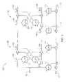
- FIGS. 1 a - 1 dillustrate four schematic diagrams of applications employing an adaptive filter
- FIG. 2is a block diagram of a RLSL structure adaptive filter according to the invention.
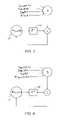
- FIG. 3is a block diagram of a backward reflection coefficient update of the adaptive filter of FIG. 2 ;
- FIG. 4is a block diagram of a forward reflection coefficient update of the adaptive filter of FIG. 2 ;
- FIG. 5is a graph illustrating backward error prediction squares for fifty samples of an input signal
- FIG. 6is a graph illustrating forward error prediction squares for fifty samples of the input signal
- FIG. 7is a graph illustrating echo return loss enhancements (ERLE) sing limited recursion for backward prediction
- FIG. 8is a graph illustrating a performance of the adaptive filter of FIG. 2 versus a number of recursions of backward error prediction squares updates.
- FIG. 9is a graph illustrating measured timing requirements versus a number of forward and backward error prediction updates
- FIG. 10is a graph illustrating measured timing requirements versus a number of forward and backward error prediction updates.
- FIG. 11is a block diagram of a communication device employing an adaptive filter.
- a method for reducing a computational complexity of an m-stage adaptive filteris provided by updating recursively forward and backward error prediction square terms for a first portion of a length of the adaptive filter, and keeping the updated forward and backward error prediction square terms constant for a second portion of the length of the adaptive filter.
- FIGS. 1 a - 1 dillustrate four schematic diagrams of filter circuits 90 employing an adaptive filter 10 .
- the filter circuits 90in general and the adaptive filter 10 may be constructed in any suitable manner.
- the adaptive filter 10may be formed using electrical components such as digital and analog integrated circuits.
- the adaptive filter 10is formed using a digital signal processor (DSP) operating in response to stored program code and data maintained in a memory.
- DSPdigital signal processor
- the DSP and memorymay be integrated in a single component such as an integrated circuit, or may be maintained separately. Further, the DSP and memory may be components of another system, such as a speech processing system or a communication device.
- an input signal u(n)is supplied to the filter circuit 90 and to the adaptive filter 10 .
- the adaptive filter 10may be configured in a multitude of arrangements between a system input and a system output. It is intended that the improvements described herein may be applied to the widest variety of applications for the adaptive filter 10 .
- the filter circuit 90includes an adaptive filter 10 , a plant 14 and a summer.
- the plant 14may be any suitable signal source being monitored.
- the input signal u(n) received at an input 12and is supplied to the adaptive filter 10 and to a signal processing plant 14 from a system input 16 .
- a filtered signal y(n) 18 produced at an output by adaptive filter 10is subtracted from a signal d(n) 20 supplied by plant 14 at an output to produce an error signal e(n) 22 .
- the error signal e(n) 22is fed back to the adaptive filter 10 .
- signal d(n) 20also represents an output signal of the system output 24 .
- the filter circuit 100includes an adaptive filter 10 , a plant 14 , a summer and a delay process 26 .
- an input signal originating from system input 16is transformed into the input signal u(n) 12 of the adaptive filter 10 by plant 14 , and converted into signal d(n) 20 by a delay process 26 .
- Filtered signal y(n) 18 of the adaptive filter 10is subtracted from signal d(n) 20 to produce error signal e(n) 22 , that is fed back to the adaptive filter 10 .
- FIG. 1 ca prediction type application of the adaptive filter 10 is shown.
- the filter circuit 100includes an adaptive filter 10 , a summer and a delay process 26 .
- adaptive filter 10 and delay process 26are arranged in series between system input 16 , now supplying a random signal input 28 , and the system output 24 .
- the random signal input 28is subtracted as signal d(n) 20 from filtered signal y(n) 18 to produce error signal e(n) 22 , that is fed back to the adaptive filter 10 .
- error signal e(n) 22also represents the output signal supplied by system output 24 .
- FIG. 1 dan interference canceling type application of the adaptive filter 10 is shown.
- the filter circuit 100includes an adaptive filter 10 and a summer.
- a reference signal 30 and a primary signal 32are provided as input signal u(n) 12 and as signal d(n) 20 , respectively.
- primary signal 32is subtracted as signal d(n) 20 from filtered signal y(n) 18 to produce error signal e(n) 22 , that is fed back to the adaptive filter 10 .
- error signal e(n) 22also represents the output signal supplied the system output 24 .
- the adaptive filter 100includes a plurality of stages including a first stage 120 and an m-th stage 122 .
- Each stage (m)may be characterized by a forward prediction error ⁇ m (n) 102 , a forward prediction error ⁇ m ⁇ 1 (n) 103 , a forward reflection coefficient K f,m ⁇ 1 (n ⁇ 1) 104 , a delayed backward prediction error ⁇ m ⁇ 1 (n) 105 , a backward prediction error ⁇ (n) 106 , a backward reflection coefficient K b,m ⁇ 1 (n ⁇ 1) 107 , an a priori estimation error backward ⁇ m (n) 108 , an a priori estimation error backward ⁇ m ⁇ 1 (n) 109 and a joint process regression coefficient K m ⁇ 1 (n ⁇ 1) 110 .
- This m-stage adaptive RLSL filter 100is shown with filter coefficients updates indicated by arrows drawn through each coefficient block. These filter coefficient updates are recursively computed for each stage (m) of a filter length of the RLSL 100 and for each sample time (n) of the input signal u(n) 12 .
- Equation 1An RLSL algorithm for the RLSL 100 is defined below in terms of Equation 1 through Equation 8.
- filter coefficient updatesare defined as follows:
- the RLSL 100is supplied by signals u(n) 12 and d(n) 20 .
- the above defined filter coefficient updatesare recursively computed.
- the forward prediction error ⁇ (n) 102is the forward prediction error ⁇ m ⁇ 1 (n) 103 of stage m ⁇ 1 augmented by a combination of the forward reflection coefficient Kf,m ⁇ 1(n ⁇ 1) 104 with the delayed backward prediction error ⁇ m ⁇ 1 (n) 105 .
- the backward prediction error ⁇ m (n) 106is the backward prediction error ⁇ m ⁇ 1 (n) 105 of stage m ⁇ 1 augmented by a combination of the backward reflection coefficient Kb,m(n ⁇ 1) 107 with the delayed forward prediction error ⁇ m ⁇ 1 (n) 103 .
- a-priori estimation error backward ⁇ m+1(n) 108for stage m at time n, is the a priori estimation error backward ⁇ m (n) 109 of stage m ⁇ 1 reduced by a combination of the joint process regression coefficient Km ⁇ 1(n ⁇ 1) 110 , of stage m ⁇ 1 at time n ⁇ 1, with the backward forward prediction error ⁇ m ⁇ 1 (n) 105 .
- the adaptive filter 100may be implemented using any suitable component or combination of components.
- the adaptive filteris implemented using a DSP in combination with instructions and data stored in an associated memory.
- the DSP and memorymay be part of any suitable system for speech processing or manipulation.
- the DSP and memorycan be a stand-alone system or embedded in another system.
- This RLSL algorithmrequires extensive computational resources and can be prohibitive for embedded systems.
- a mechanism for reducing the computational requirements of an RLSL adaptive filter 100is obtained by reducing a number of calculated updates of the forward error prediction squares Fm(n) from backward error prediction squares Bm (n).
- processorsare substantially efficient at adding, subtracting and multiplying, but not necessarily at dividing.
- Most processorsuse a successive approximation technique to implement a divide instruction and may require multiple clock cycles to produce a result.
- a total number of computations in the filter coefficient updatesmay need to be reduced as well as a number of divides that are required in the calculations of the filter coefficient updates.
- the RLSL algorithm filter coefficient updatesare transformed to consolidate the divides.
- the time (n) and order (m) indices of the RLSL algorithmare translated to form Equation 9 through Equation 17.
- B m ′ ⁇ ( n )B m ′ ⁇ ( n - 1 ) ⁇ + B m ′ ⁇ ( n - 1 ) ⁇ ⁇ m ⁇ ( n ) ⁇ ⁇ ⁇ m ⁇ ( n ) ⁇ 2 Equation ⁇ ⁇ 21
- FIG. 3a block diagram of the backward reflection coefficient update Kb,m(n) 30 as evaluated in Equation 25 is shown.
- the block diagram of FIG. 3is representative of, for example, a DSP operation or group of operations.
- the backward reflection coefficient update Kb,m(n) 30is supplied to a delay 32 and the output of delay 32 Kb,m(n ⁇ 1) is summed to a product of the forward error prediction squares F′m (n) with the backward prediction error ⁇ m(n), the forward prediction error ⁇ m ⁇ 1(n), and the conversion factor ⁇ m(n ⁇ 1).
- FIG. 4a block diagram of the forward reflection coefficient update Kf,m(n) 40 as evaluated in Equation 28 is shown. Similar to FIG. 3 , the block diagram of FIG. 4 is representative of, for example, a DSP operation or group of operations.
- the backward reflection coefficient update Kb,m(n) 40is supplied to a delay 42 .
- the output of delay 42 Kf,m(n ⁇ 1)is summed to a product of the backward error prediction squares B′m ⁇ 1 (n ⁇ 1) with the backward prediction error ⁇ m ⁇ 1(n), the forward prediction error ⁇ m(n), and the conversion faction ⁇ m ⁇ 1(n ⁇ 1).
- the forward and backward error prediction squares, Fm (n) and Bm(n)are plotted against the length of the filter for 50 samples of input signal u(n) 12 during a condition of high convergence. These plots clearly indicate that the error prediction squares Fm (n) and Bm(n), ramp up quickly and then flatten out for the higher order taps of the adaptive filter 10 . As such, one can infer that most of the information is substantially contained in the first few recursions of the RLSL algorithm and that a reduction in the number of coefficient updates can achieve acceptable filter performance.
- a good mechanism for trading performance with computational requirementsis to reduce the number of recursions or updates performed on the forward and backward error prediction squares, Fm (n) and Bm(n), to a predefined portion of the filter length. Then, the error prediction squares are held constant for the remainder of the filter tap updates.
- Fm (n) and Bm(n)forward and backward error prediction squares
- FIG. 8illustrates graphically the loss in performance of a 360 tap filter when the forward and backward error prediction squares, Fm (n) and Bm(n), are held constant after only 100 updates of the filter.
- This graphshows the echo return loss enhancement (ERLE) in dB of the filter for a 360 tap filter for both the full filter update and one with the error prediction updates calculated for only the first 100 taps of the 360 tap filter.
- ERLEecho return loss enhancement
- this process of limiting updates performed on the forward and backward error prediction squares, Fm (n) and Bm(n), to a predefined portion of the filter lengthwas repeated for different limits applied to the number of error prediction updates and plotted against the ERLE of the adaptive filter 10 .
- This plot of FIG. 9shows how the filter performance degrades as the number of error prediction updates is reduced.
- this FIG. 9 plotindicates that there is minimal improvement in filter performance in updating the error prediction squares beyond about 180 (half) filter taps.
- FIG. 10a graph illustrating measured timing requirements versus a number of forward and backward error prediction updates, Fm (n) and Bm(n).
- This FIG. 10 graphis included to serve as an aide in determining the proper trade-off between computational requirements and peak filter performance.
- This graphplots the measured timing requirements of the RLSL filter 10 vs. the number of forward and backward error prediction squares updated for a 360 tap length filter. These values reflect measurements taken on a real-time hardware implementation. As expected the timing decreases linearly as the number of updates is reduced.
- the recursion loopis broken into two parts.
- the first partis the full set of updates as shown in Equation 22 through Equation 30. These updates are performed as normal up to a predefined number of taps of the filter. The exact number of taps needed of course is determined by the trade off analysis between real time and filter performance.
- the second part of the optimized RLSL algorithmis given by Equation 31 through Equation 37. In these series of recursive updates, the forward and backward error prediction squares, Fm (n) and Bm(n), are held constant at the last value calculated from the first part of the optimized algorithm.
- the forward error prediction square term (Fc)remains constant and is used in Equation 32 to update the backward reflection coefficient Kb,m(n).
- the backward error prediction square term (Bc)remains constant for the remainder of the filter updates and is used in Equation 34 to update the forward reflection coefficient Kf,m(n).
- FIG. 11is a block diagram of a communication device 1100 employing an adaptive filter.
- the communication device 1100includes a DSP 1102 , a microphone 1104 , a speaker 1106 , an analog signal processor 1108 and a network connection 1110 .
- the DSP 1102may be any processing device including a commercially available digital signal processor adapted to process audio and other information.
- the communication device 1100includes a microphone 1104 and speaker 1106 and analog signal processor 1108 .
- the microphone 1104converts sound waves impressed thereon to electrical signals.
- the speaker 1106converts electrical signals to audible sound waves.
- the analog signal processor 1108serves as an interface between the DSP, which operates on digital data representative of the electrical signals, and the electrical signals useful to the microphone 1104 and 1106 .
- the analog signal processor 1108may be integrated with the DSP 1102 .
- the network connection 1110provides communication of data and other information between the communication device 1100 and other components. This communication may be over a wire line, over a wireless link, or a combination of the two.
- the communication device 1100may be embodied as a cellular telephone and the adaptive filter 1112 operates to process audio information for the user of the cellular telephone.
- the network connection 1110is formed by the radio interface circuit that communicates with a remote base station.
- the communication device 1100is embodied as a hands-free, in-vehicle audio system and the adaptive filter 1112 is operative to serve as part of a double-talk detector of the system.
- the network connection 1110is formed by a wire line connection over a communication bus of the vehicle.
- the DSP 1102includes data and instructions to implement an adaptive filter 1112 , a memory 1114 for storing data and instructions and a processor 1116 .
- the adaptive filter 1112 in this embodimentis an RLSL adaptive filter of the type generally described herein.
- the adaptive filter 1112is enhanced to reduce the number of calculations required to implement the RLSL algorithm as described herein.
- the adaptive filter 1112may include additional enhancements and capabilities beyond those expressly described herein.
- the processor 1116operates in response to the data and instructions implementing the adaptive filter 1112 and other data and instructions stored in the memory 1114 to process audio and other information of the communication device 1100 .
- the adaptive filter 1112receives an input signal from a source and provides a filtered signal as an output.
- the DSP 1102receives digital data from either the analog signal processor 1108 or the network interface 1110 .
- the analog signal processor 1108 and the network interface 1110thus form means for receiving an input signal.
- the digital datais representative of a time-varying signal and forms the input signal.
- the processor 1116 of DSP 1102implements the adaptive filter 1112 .
- the data forming the input signalis provided to the instructions and data forming the adaptive filter.
- the adaptive filter 1112produces an output signal in the form of output data.
- the output datamay be further processed by the DSP 1102 or passed to the analog signal processor 1108 or the network interface 1110 for further processing.
- the communication device 1100may be modified and adapted to other embodiments as well.
- the embodiments shown and described hereinare intended to be exemplary only.
Landscapes
- Filters That Use Time-Delay Elements (AREA)
Abstract
Description
- Fm(n) Weighted sum of forward prediction error squares for stage m at time n.
- Bm(n) Weighted sum of backward prediction error squares for stage m at time n.
- ηm(n) Forward prediction error.
- βm(n) Backward prediction error.
- Kb,m(n) Backward reflection coefficient for stage m at time n.
- Kf,m(n) Forward reflection coefficient for stage m at time n.
- Km(n) Joint process regression coefficient for stage m at time n.
- γm(n) Conversion factor for stage m at time n.
- ξm(n) A priori estimation error for stage m at time n.
- λ Exponential weighting factor or gain factor.
βm(n)=βm−1(n−1)+Kb,m(n−1)ηm−1(n) Equation 31
Kb,m(n)=Kb,m(n−1)−γm−1(n−1)ηm−1(n)βm(n)Fc Equation 32
ηm(n)=ηm−1(n)+Kf,m(n−1)βm−1(n−1) Equation 33
Kf,m(n)=Kf,m(n−1)−γm−1(n−1)βm−1(n−1)ηm(n)Bc Equation 34
ξm(n)=ξm−1(n)−Km−1(n−1)βm−1(n)
Km(n)=Km(n−1)+γm(n)βm(n)ξm+1(n)Bc Equation 36
γm(n)=γm−1(n)−γ2m−1(n)|βm−1(n)|2Bc Equation 37
Claims (11)
Priority Applications (3)
| Application Number | Priority Date | Filing Date | Title |
|---|---|---|---|
| US11/399,907US7734466B2 (en) | 2005-06-20 | 2006-04-07 | Reduced complexity recursive least square lattice structure adaptive filter by means of limited recursion of the backward and forward error prediction squares |
| CN2006800218486ACN101496001B (en) | 2005-06-20 | 2006-06-08 | Reduced Complexity Recursive Least Squares Lattice Adaptive Filters via Finite Recursion of Squared Backward and Forward Error Prediction |
| PCT/US2006/022286WO2007001786A2 (en) | 2005-06-20 | 2006-06-08 | A reduced complexity recursive least square lattice structure adaptive filter by means of limited recursion of the backward and forward error prediction squares |
Applications Claiming Priority (4)
| Application Number | Priority Date | Filing Date | Title |
|---|---|---|---|
| US69234505P | 2005-06-20 | 2005-06-20 | |
| US69223605P | 2005-06-20 | 2005-06-20 | |
| US69234705P | 2005-06-20 | 2005-06-20 | |
| US11/399,907US7734466B2 (en) | 2005-06-20 | 2006-04-07 | Reduced complexity recursive least square lattice structure adaptive filter by means of limited recursion of the backward and forward error prediction squares |
Publications (2)
| Publication Number | Publication Date |
|---|---|
| US20060288066A1 US20060288066A1 (en) | 2006-12-21 |
| US7734466B2true US7734466B2 (en) | 2010-06-08 |
Family
ID=37574651
Family Applications (1)
| Application Number | Title | Priority Date | Filing Date |
|---|---|---|---|
| US11/399,907Expired - Fee RelatedUS7734466B2 (en) | 2005-06-20 | 2006-04-07 | Reduced complexity recursive least square lattice structure adaptive filter by means of limited recursion of the backward and forward error prediction squares |
Country Status (1)
| Country | Link |
|---|---|
| US (1) | US7734466B2 (en) |
Cited By (3)
| Publication number | Priority date | Publication date | Assignee | Title |
|---|---|---|---|---|
| US20110022382A1 (en)* | 2005-08-19 | 2011-01-27 | Trident Microsystems (Far East) Ltd. | Adaptive Reduction of Noise Signals and Background Signals in a Speech-Processing System |
| US10403299B2 (en) | 2017-06-02 | 2019-09-03 | Apple Inc. | Multi-channel speech signal enhancement for robust voice trigger detection and automatic speech recognition |
| US12407547B2 (en) | 2023-01-19 | 2025-09-02 | Samsung Electronics Co., Ltd. | Adaptive filter circuit having low complexity and flexible structure and device including the same |
Families Citing this family (2)
| Publication number | Priority date | Publication date | Assignee | Title |
|---|---|---|---|---|
| US7702711B2 (en)* | 2005-06-20 | 2010-04-20 | Motorola, Inc. | Reduced complexity recursive least square lattice structure adaptive filter by means of estimating the backward and forward error prediction squares using binomial expansion |
| US20060288067A1 (en)* | 2005-06-20 | 2006-12-21 | Motorola, Inc. | Reduced complexity recursive least square lattice structure adaptive filter by means of approximating the forward error prediction squares using the backward error prediction squares |
Citations (47)
| Publication number | Priority date | Publication date | Assignee | Title |
|---|---|---|---|---|
| US4179709A (en)* | 1978-01-10 | 1979-12-18 | Bell & Howell Company | Video information bandwidth compression |
| US4521907A (en)* | 1982-05-25 | 1985-06-04 | American Microsystems, Incorporated | Multiplier/adder circuit |
| US4972483A (en)* | 1987-09-24 | 1990-11-20 | Newbridge Networks Corporation | Speech processing system using adaptive vector quantization |
| US4979211A (en)* | 1988-11-16 | 1990-12-18 | At&T Bell Laboratories | Classifier for high speed voiceband digital data modem signals |
| US5157690A (en)* | 1990-10-30 | 1992-10-20 | Level One Communications, Inc. | Adaptive convergent decision feedback equalizer |
| US5307375A (en)* | 1992-11-19 | 1994-04-26 | General Instrument Corporation | Two stage accumulator for use in updating coefficients |
| US5353372A (en)* | 1992-01-27 | 1994-10-04 | The Board Of Trustees Of The Leland Stanford Junior University | Accurate pitch measurement and tracking system and method |
| US5353307A (en) | 1991-09-03 | 1994-10-04 | General Electric Company | Automatic simulcast alignment |
| US5418714A (en) | 1993-04-08 | 1995-05-23 | Eyesys Laboratories, Inc. | Method and apparatus for variable block size interpolative coding of images |
| US5432816A (en) | 1992-04-10 | 1995-07-11 | International Business Machines Corporation | System and method of robust sequence estimation in the presence of channel mismatch conditions |
| US5432821A (en) | 1992-12-02 | 1995-07-11 | University Of Southern California | System and method for estimating data sequences in digital transmissions |
| US5434948A (en)* | 1989-06-15 | 1995-07-18 | British Telecommunications Public Limited Company | Polyphonic coding |
| US5513215A (en) | 1993-09-20 | 1996-04-30 | Glenayre Electronics, Inc. | High speed simulcast data system using adaptive compensation |
| US5539858A (en)* | 1991-05-31 | 1996-07-23 | Kokusai Electric Co. Ltd. | Voice coding communication system and apparatus |
| US5615208A (en) | 1993-04-08 | 1997-03-25 | Ant Nachrichtentechnik Gmbh | Kalman filter for channel impulse-response adaption in receivers for TDMA mobile radio systems |
| US5649012A (en)* | 1995-09-15 | 1997-07-15 | Hughes Electronics | Method for synthesizing an echo path in an echo canceller |
| US5657350A (en)* | 1993-05-05 | 1997-08-12 | U.S. Philips Corporation | Audio coder/decoder with recursive determination of prediction coefficients based on reflection coefficients derived from correlation coefficients |
| US5809463A (en)* | 1995-09-15 | 1998-09-15 | Hughes Electronics | Method of detecting double talk in an echo canceller |
| US5809086A (en) | 1996-03-20 | 1998-09-15 | Lucent Technologies Inc. | Intelligent timing recovery for a broadband adaptive equalizer |
| US5844951A (en) | 1994-06-10 | 1998-12-01 | Northeastern University | Method and apparatus for simultaneous beamforming and equalization |
| US20010005822A1 (en)* | 1999-12-13 | 2001-06-28 | Fujitsu Limited | Noise suppression apparatus realized by linear prediction analyzing circuit |
| US20010021940A1 (en)* | 2000-03-10 | 2001-09-13 | Fujitsu Limited | Method of updating reflection coefficients of lattice filter and apparatus for updating such reflection coefficients |
| US6353629B1 (en) | 1997-05-12 | 2002-03-05 | Texas Instruments Incorporated | Poly-path time domain equalization |
| US6381272B1 (en)* | 1998-03-24 | 2002-04-30 | Texas Instruments Incorporated | Multi-channel adaptive filtering |
| US6442274B1 (en)* | 1998-12-28 | 2002-08-27 | Nec Corporation | Method and apparatus of canceling echoes in multi-channel |
| US6445692B1 (en) | 1998-05-20 | 2002-09-03 | The Trustees Of The Stevens Institute Of Technology | Blind adaptive algorithms for optimal minimum variance CDMA receivers |
| US20020147584A1 (en)* | 2001-01-05 | 2002-10-10 | Hardwick John C. | Lossless audio coder |
| US20030023650A1 (en) | 2001-07-25 | 2003-01-30 | Apostolis Papathanasiou | Adaptive filter for communication system |
| US6643676B1 (en) | 2000-04-19 | 2003-11-04 | Virata Corporation | Initialization /prewindowing removal postprocessing for fast RLS filter adaptation |
| US6658071B1 (en) | 2000-02-14 | 2003-12-02 | Ericsson Inc. | Delayed decision feedback log-map equalizer |
| US6678230B2 (en)* | 2000-10-31 | 2004-01-13 | Matsushita Electric Industrial Co., Ltd. | Waveform equalizer for a reproduction signal obtained by reproducing marks and non-marks recorded on a recording medium |
| US6760374B1 (en) | 2000-09-19 | 2004-07-06 | Rockwell Collins, Inc. | Block decision feedback equalization method and apparatus |
| US6763064B1 (en) | 2000-09-21 | 2004-07-13 | Rockwell Collins | Block decision directed equalization method and apparatus |
| US6801565B1 (en) | 1999-06-25 | 2004-10-05 | Ericsson Inc. | Multi-stage rake combining methods and apparatus |
| US6810073B1 (en) | 1999-12-09 | 2004-10-26 | Telefonaktiebolaget Lm Ericsson (Publ) | Method and system for interference cancellation using multiple filter sets and normalized filter adaptation |
| US20050075866A1 (en)* | 2003-10-06 | 2005-04-07 | Bernard Widrow | Speech enhancement in the presence of background noise |
| US20050123129A1 (en)* | 2003-11-21 | 2005-06-09 | Awad Thomas J. | Method and apparatus for reducing echo in a communication system |
| US6947550B2 (en)* | 2002-04-30 | 2005-09-20 | Innomedia Pte Ltd. | Acoustic echo cancellation |
| US6963833B1 (en)* | 1999-10-26 | 2005-11-08 | Sasken Communication Technologies Limited | Modifications in the multi-band excitation (MBE) model for generating high quality speech at low bit rates |
| US7027504B2 (en) | 2001-09-18 | 2006-04-11 | Broadcom Corporation | Fast computation of decision feedback equalizer coefficients |
| US7113540B2 (en) | 2001-09-18 | 2006-09-26 | Broadcom Corporation | Fast computation of multi-input-multi-output decision feedback equalizer coefficients |
| US20060288064A1 (en)* | 2005-06-20 | 2006-12-21 | Barron David L | Reduced complexity recursive least square lattice structure adaptive filter by means of estimating the backward and forward error prediction squares using binomial expansion |
| US20060288067A1 (en)* | 2005-06-20 | 2006-12-21 | Motorola, Inc. | Reduced complexity recursive least square lattice structure adaptive filter by means of approximating the forward error prediction squares using the backward error prediction squares |
| US7170924B2 (en) | 2001-05-17 | 2007-01-30 | Qualcomm, Inc. | System and method for adjusting combiner weights using an adaptive algorithm in wireless communications system |
| US7277472B2 (en)* | 2001-04-16 | 2007-10-02 | Huawei Technologies Co., Ltd. | Estimation method of flat fading channel in CDMA communication system and apparatus for the same |
| US7299251B2 (en) | 2000-11-08 | 2007-11-20 | Qinetiq Limited | Adaptive filter |
| US7530955B2 (en) | 1991-03-07 | 2009-05-12 | Masimo Corporation | Signal processing apparatus |
- 2006
- 2006-04-07USUS11/399,907patent/US7734466B2/ennot_activeExpired - Fee Related
Patent Citations (49)
| Publication number | Priority date | Publication date | Assignee | Title |
|---|---|---|---|---|
| US4179709A (en)* | 1978-01-10 | 1979-12-18 | Bell & Howell Company | Video information bandwidth compression |
| US4521907A (en)* | 1982-05-25 | 1985-06-04 | American Microsystems, Incorporated | Multiplier/adder circuit |
| US4972483A (en)* | 1987-09-24 | 1990-11-20 | Newbridge Networks Corporation | Speech processing system using adaptive vector quantization |
| US4979211A (en)* | 1988-11-16 | 1990-12-18 | At&T Bell Laboratories | Classifier for high speed voiceband digital data modem signals |
| US5434948A (en)* | 1989-06-15 | 1995-07-18 | British Telecommunications Public Limited Company | Polyphonic coding |
| US5157690A (en)* | 1990-10-30 | 1992-10-20 | Level One Communications, Inc. | Adaptive convergent decision feedback equalizer |
| US7530955B2 (en) | 1991-03-07 | 2009-05-12 | Masimo Corporation | Signal processing apparatus |
| US5539858A (en)* | 1991-05-31 | 1996-07-23 | Kokusai Electric Co. Ltd. | Voice coding communication system and apparatus |
| US5353307A (en) | 1991-09-03 | 1994-10-04 | General Electric Company | Automatic simulcast alignment |
| US5353372A (en)* | 1992-01-27 | 1994-10-04 | The Board Of Trustees Of The Leland Stanford Junior University | Accurate pitch measurement and tracking system and method |
| US5432816A (en) | 1992-04-10 | 1995-07-11 | International Business Machines Corporation | System and method of robust sequence estimation in the presence of channel mismatch conditions |
| US5307375A (en)* | 1992-11-19 | 1994-04-26 | General Instrument Corporation | Two stage accumulator for use in updating coefficients |
| US5432821A (en) | 1992-12-02 | 1995-07-11 | University Of Southern California | System and method for estimating data sequences in digital transmissions |
| US5418714A (en) | 1993-04-08 | 1995-05-23 | Eyesys Laboratories, Inc. | Method and apparatus for variable block size interpolative coding of images |
| US5615208A (en) | 1993-04-08 | 1997-03-25 | Ant Nachrichtentechnik Gmbh | Kalman filter for channel impulse-response adaption in receivers for TDMA mobile radio systems |
| US5657350A (en)* | 1993-05-05 | 1997-08-12 | U.S. Philips Corporation | Audio coder/decoder with recursive determination of prediction coefficients based on reflection coefficients derived from correlation coefficients |
| US5513215A (en) | 1993-09-20 | 1996-04-30 | Glenayre Electronics, Inc. | High speed simulcast data system using adaptive compensation |
| US5844951A (en) | 1994-06-10 | 1998-12-01 | Northeastern University | Method and apparatus for simultaneous beamforming and equalization |
| US5809463A (en)* | 1995-09-15 | 1998-09-15 | Hughes Electronics | Method of detecting double talk in an echo canceller |
| US5649012A (en)* | 1995-09-15 | 1997-07-15 | Hughes Electronics | Method for synthesizing an echo path in an echo canceller |
| US5809086A (en) | 1996-03-20 | 1998-09-15 | Lucent Technologies Inc. | Intelligent timing recovery for a broadband adaptive equalizer |
| US6353629B1 (en) | 1997-05-12 | 2002-03-05 | Texas Instruments Incorporated | Poly-path time domain equalization |
| US6381272B1 (en)* | 1998-03-24 | 2002-04-30 | Texas Instruments Incorporated | Multi-channel adaptive filtering |
| US6445692B1 (en) | 1998-05-20 | 2002-09-03 | The Trustees Of The Stevens Institute Of Technology | Blind adaptive algorithms for optimal minimum variance CDMA receivers |
| US6442274B1 (en)* | 1998-12-28 | 2002-08-27 | Nec Corporation | Method and apparatus of canceling echoes in multi-channel |
| US6801565B1 (en) | 1999-06-25 | 2004-10-05 | Ericsson Inc. | Multi-stage rake combining methods and apparatus |
| US6963833B1 (en)* | 1999-10-26 | 2005-11-08 | Sasken Communication Technologies Limited | Modifications in the multi-band excitation (MBE) model for generating high quality speech at low bit rates |
| US6810073B1 (en) | 1999-12-09 | 2004-10-26 | Telefonaktiebolaget Lm Ericsson (Publ) | Method and system for interference cancellation using multiple filter sets and normalized filter adaptation |
| US20010005822A1 (en)* | 1999-12-13 | 2001-06-28 | Fujitsu Limited | Noise suppression apparatus realized by linear prediction analyzing circuit |
| US6658071B1 (en) | 2000-02-14 | 2003-12-02 | Ericsson Inc. | Delayed decision feedback log-map equalizer |
| US20010021940A1 (en)* | 2000-03-10 | 2001-09-13 | Fujitsu Limited | Method of updating reflection coefficients of lattice filter and apparatus for updating such reflection coefficients |
| US6643676B1 (en) | 2000-04-19 | 2003-11-04 | Virata Corporation | Initialization /prewindowing removal postprocessing for fast RLS filter adaptation |
| US6760374B1 (en) | 2000-09-19 | 2004-07-06 | Rockwell Collins, Inc. | Block decision feedback equalization method and apparatus |
| US6763064B1 (en) | 2000-09-21 | 2004-07-13 | Rockwell Collins | Block decision directed equalization method and apparatus |
| US6678230B2 (en)* | 2000-10-31 | 2004-01-13 | Matsushita Electric Industrial Co., Ltd. | Waveform equalizer for a reproduction signal obtained by reproducing marks and non-marks recorded on a recording medium |
| US7299251B2 (en) | 2000-11-08 | 2007-11-20 | Qinetiq Limited | Adaptive filter |
| US6675148B2 (en)* | 2001-01-05 | 2004-01-06 | Digital Voice Systems, Inc. | Lossless audio coder |
| US20020147584A1 (en)* | 2001-01-05 | 2002-10-10 | Hardwick John C. | Lossless audio coder |
| US7277472B2 (en)* | 2001-04-16 | 2007-10-02 | Huawei Technologies Co., Ltd. | Estimation method of flat fading channel in CDMA communication system and apparatus for the same |
| US7170924B2 (en) | 2001-05-17 | 2007-01-30 | Qualcomm, Inc. | System and method for adjusting combiner weights using an adaptive algorithm in wireless communications system |
| US20030023650A1 (en) | 2001-07-25 | 2003-01-30 | Apostolis Papathanasiou | Adaptive filter for communication system |
| US7027504B2 (en) | 2001-09-18 | 2006-04-11 | Broadcom Corporation | Fast computation of decision feedback equalizer coefficients |
| US7113540B2 (en) | 2001-09-18 | 2006-09-26 | Broadcom Corporation | Fast computation of multi-input-multi-output decision feedback equalizer coefficients |
| US6947550B2 (en)* | 2002-04-30 | 2005-09-20 | Innomedia Pte Ltd. | Acoustic echo cancellation |
| US20050075866A1 (en)* | 2003-10-06 | 2005-04-07 | Bernard Widrow | Speech enhancement in the presence of background noise |
| US20050123129A1 (en)* | 2003-11-21 | 2005-06-09 | Awad Thomas J. | Method and apparatus for reducing echo in a communication system |
| US7231234B2 (en)* | 2003-11-21 | 2007-06-12 | Octasic Inc. | Method and apparatus for reducing echo in a communication system |
| US20060288067A1 (en)* | 2005-06-20 | 2006-12-21 | Motorola, Inc. | Reduced complexity recursive least square lattice structure adaptive filter by means of approximating the forward error prediction squares using the backward error prediction squares |
| US20060288064A1 (en)* | 2005-06-20 | 2006-12-21 | Barron David L | Reduced complexity recursive least square lattice structure adaptive filter by means of estimating the backward and forward error prediction squares using binomial expansion |
Non-Patent Citations (6)
| Title |
|---|
| Cioffi, J., "The Fast Householder Filters RLS Adaptive Filter," IEEE, pp. 1619-1622 (1990). |
| International Search Report and Written Opinion for International Application No. PCT/US2006/022286, mailed Mar. 24, 2008 (8 pages). |
| Marple, S. Lawrence, "Two-Dimensional Lattice Linear Prediction Parameter Estimation Method and Fast Algorithm," 7(6) IEEE Signal Processing Letters 164-168 (Jun. 2000). |
| Meng, Julian, "A Modified Recursive Least Squares Adaptive Lattice Filter for Narrowband Interference Rejection," IEEE, pp. 969-972 (May 2003). |
| Merched, Ricardo, et al., "Extended Fast Fixed Order RLS Adaptive Filters," IEEE, pp. II-665 to II-668 (2001). |
| Merched, Ricardo, et al., "Extended Fast Fixed-Order RLS Adaptive Filters," 49(12) IEEE Transactions on Signal Processing 3015-3031 (Dec. 2001). |
Cited By (4)
| Publication number | Priority date | Publication date | Assignee | Title |
|---|---|---|---|---|
| US20110022382A1 (en)* | 2005-08-19 | 2011-01-27 | Trident Microsystems (Far East) Ltd. | Adaptive Reduction of Noise Signals and Background Signals in a Speech-Processing System |
| US8352256B2 (en)* | 2005-08-19 | 2013-01-08 | Entropic Communications, Inc. | Adaptive reduction of noise signals and background signals in a speech-processing system |
| US10403299B2 (en) | 2017-06-02 | 2019-09-03 | Apple Inc. | Multi-channel speech signal enhancement for robust voice trigger detection and automatic speech recognition |
| US12407547B2 (en) | 2023-01-19 | 2025-09-02 | Samsung Electronics Co., Ltd. | Adaptive filter circuit having low complexity and flexible structure and device including the same |
Also Published As
| Publication number | Publication date |
|---|---|
| US20060288066A1 (en) | 2006-12-21 |
Similar Documents
| Publication | Publication Date | Title |
|---|---|---|
| US9538285B2 (en) | Real-time microphone array with robust beamformer and postfilter for speech enhancement and method of operation thereof | |
| EP0995188B1 (en) | Methods and apparatus for measuring signal level and delay at multiple sensors | |
| US8594173B2 (en) | Method for determining updated filter coefficients of an adaptive filter adapted by an LMS algorithm with pre-whitening | |
| US6236725B1 (en) | Echo canceler employing multiple step gains | |
| US20040264610A1 (en) | Interference cancelling method and system for multisensor antenna | |
| AU751333B2 (en) | Method and device for blind equalizing of transmission channel effects on a digital speech signal | |
| US20040047464A1 (en) | Adaptive noise cancelling microphone system | |
| US20040057574A1 (en) | Suppression of echo signals and the like | |
| US8184828B2 (en) | Background noise estimation utilizing time domain and spectral domain smoothing filtering | |
| US20040078200A1 (en) | Noise reduction in subbanded speech signals | |
| US20020013695A1 (en) | Method for noise suppression in an adaptive beamformer | |
| CN102165707A (en) | echo canceller | |
| Petillon et al. | The fast Newton transversal filter: An efficient scheme for acoustic echo cancellation in mobile radio | |
| JPH06318885A (en) | Unknown system identifying method/device using band division adaptive filter | |
| US7734466B2 (en) | Reduced complexity recursive least square lattice structure adaptive filter by means of limited recursion of the backward and forward error prediction squares | |
| EP0711035B1 (en) | System identification method apparatus by adaptive filter | |
| KR20010043833A (en) | Signal noise reduction by spectral subtraction using spectrum dependent exponential gain function averaging | |
| US7778408B2 (en) | Method and apparatus for acoustic echo cancellation utilizing dual filters | |
| US20070121926A1 (en) | Double-talk detector for an acoustic echo canceller | |
| US6970558B1 (en) | Method and device for suppressing noise in telephone devices | |
| KR20220157475A (en) | Echo Residual Suppression | |
| US7702711B2 (en) | Reduced complexity recursive least square lattice structure adaptive filter by means of estimating the backward and forward error prediction squares using binomial expansion | |
| Costa et al. | A robust variable step size algorithm for LMS adaptive filters | |
| JP5374845B2 (en) | Noise estimation apparatus and method, and program | |
| AU4869200A (en) | Apparatus and method for estimating an echo path delay |
Legal Events
| Date | Code | Title | Description |
|---|---|---|---|
| AS | Assignment | Owner name:MOTOROLA, INC.,ILLINOIS Free format text:ASSIGNMENT OF ASSIGNORS INTEREST;ASSIGNORS:BARRON, DAVID L.;IWAI, KYLE K.;PIKET, JAMES B.;REEL/FRAME:017741/0153 Effective date:20060406 Owner name:MOTOROLA, INC., ILLINOIS Free format text:ASSIGNMENT OF ASSIGNORS INTEREST;ASSIGNORS:BARRON, DAVID L.;IWAI, KYLE K.;PIKET, JAMES B.;REEL/FRAME:017741/0153 Effective date:20060406 | |
| STCF | Information on status: patent grant | Free format text:PATENTED CASE | |
| AS | Assignment | Owner name:MOTOROLA MOBILITY, INC, ILLINOIS Free format text:ASSIGNMENT OF ASSIGNORS INTEREST;ASSIGNOR:MOTOROLA, INC;REEL/FRAME:025673/0558 Effective date:20100731 | |
| AS | Assignment | Owner name:MOTOROLA MOBILITY LLC, ILLINOIS Free format text:CHANGE OF NAME;ASSIGNOR:MOTOROLA MOBILITY, INC.;REEL/FRAME:029216/0282 Effective date:20120622 | |
| FPAY | Fee payment | Year of fee payment:4 | |
| AS | Assignment | Owner name:GOOGLE TECHNOLOGY HOLDINGS LLC, CALIFORNIA Free format text:ASSIGNMENT OF ASSIGNORS INTEREST;ASSIGNOR:MOTOROLA MOBILITY LLC;REEL/FRAME:034420/0001 Effective date:20141028 | |
| MAFP | Maintenance fee payment | Free format text:PAYMENT OF MAINTENANCE FEE, 8TH YEAR, LARGE ENTITY (ORIGINAL EVENT CODE: M1552) Year of fee payment:8 | |
| FEPP | Fee payment procedure | Free format text:MAINTENANCE FEE REMINDER MAILED (ORIGINAL EVENT CODE: REM.); ENTITY STATUS OF PATENT OWNER: LARGE ENTITY | |
| LAPS | Lapse for failure to pay maintenance fees | Free format text:PATENT EXPIRED FOR FAILURE TO PAY MAINTENANCE FEES (ORIGINAL EVENT CODE: EXP.); ENTITY STATUS OF PATENT OWNER: LARGE ENTITY | |
| STCH | Information on status: patent discontinuation | Free format text:PATENT EXPIRED DUE TO NONPAYMENT OF MAINTENANCE FEES UNDER 37 CFR 1.362 | |
| FP | Lapsed due to failure to pay maintenance fee | Effective date:20220608 |