US7733794B2 - Performance monitoring of frame transmission in data network OAM protocols - Google Patents
Performance monitoring of frame transmission in data network OAM protocolsDownload PDFInfo
- Publication number
- US7733794B2 US7733794B2US11/383,741US38374106AUS7733794B2US 7733794 B2US7733794 B2US 7733794B2US 38374106 AUS38374106 AUS 38374106AUS 7733794 B2US7733794 B2US 7733794B2
- Authority
- US
- United States
- Prior art keywords
- performance monitoring
- frames
- frame
- performance
- interval
- Prior art date
- Legal status (The legal status is an assumption and is not a legal conclusion. Google has not performed a legal analysis and makes no representation as to the accuracy of the status listed.)
- Expired - Fee Related, expires
Links
Images


Classifications
- H—ELECTRICITY
- H04—ELECTRIC COMMUNICATION TECHNIQUE
- H04L—TRANSMISSION OF DIGITAL INFORMATION, e.g. TELEGRAPHIC COMMUNICATION
- H04L47/00—Traffic control in data switching networks
- H04L47/10—Flow control; Congestion control
- H04L47/20—Traffic policing
- H—ELECTRICITY
- H04—ELECTRIC COMMUNICATION TECHNIQUE
- H04L—TRANSMISSION OF DIGITAL INFORMATION, e.g. TELEGRAPHIC COMMUNICATION
- H04L41/00—Arrangements for maintenance, administration or management of data switching networks, e.g. of packet switching networks
- H04L41/14—Network analysis or design
- H04L41/142—Network analysis or design using statistical or mathematical methods
- H—ELECTRICITY
- H04—ELECTRIC COMMUNICATION TECHNIQUE
- H04L—TRANSMISSION OF DIGITAL INFORMATION, e.g. TELEGRAPHIC COMMUNICATION
- H04L43/00—Arrangements for monitoring or testing data switching networks
- H04L43/06—Generation of reports
- H04L43/067—Generation of reports using time frame reporting
- H—ELECTRICITY
- H04—ELECTRIC COMMUNICATION TECHNIQUE
- H04L—TRANSMISSION OF DIGITAL INFORMATION, e.g. TELEGRAPHIC COMMUNICATION
- H04L43/00—Arrangements for monitoring or testing data switching networks
- H04L43/08—Monitoring or testing based on specific metrics, e.g. QoS, energy consumption or environmental parameters
- H04L43/0852—Delays
- H04L43/0858—One way delays
- H—ELECTRICITY
- H04—ELECTRIC COMMUNICATION TECHNIQUE
- H04L—TRANSMISSION OF DIGITAL INFORMATION, e.g. TELEGRAPHIC COMMUNICATION
- H04L43/00—Arrangements for monitoring or testing data switching networks
- H04L43/10—Active monitoring, e.g. heartbeat, ping or trace-route
- H04L43/106—Active monitoring, e.g. heartbeat, ping or trace-route using time related information in packets, e.g. by adding timestamps
- H—ELECTRICITY
- H04—ELECTRIC COMMUNICATION TECHNIQUE
- H04L—TRANSMISSION OF DIGITAL INFORMATION, e.g. TELEGRAPHIC COMMUNICATION
- H04L45/00—Routing or path finding of packets in data switching networks
- H04L45/50—Routing or path finding of packets in data switching networks using label swapping, e.g. multi-protocol label switch [MPLS]
- H—ELECTRICITY
- H04—ELECTRIC COMMUNICATION TECHNIQUE
- H04L—TRANSMISSION OF DIGITAL INFORMATION, e.g. TELEGRAPHIC COMMUNICATION
- H04L47/00—Traffic control in data switching networks
- H04L47/10—Flow control; Congestion control
- H04L47/11—Identifying congestion
- H—ELECTRICITY
- H04—ELECTRIC COMMUNICATION TECHNIQUE
- H04L—TRANSMISSION OF DIGITAL INFORMATION, e.g. TELEGRAPHIC COMMUNICATION
- H04L47/00—Traffic control in data switching networks
- H04L47/10—Flow control; Congestion control
- H04L47/24—Traffic characterised by specific attributes, e.g. priority or QoS
- H04L47/2425—Traffic characterised by specific attributes, e.g. priority or QoS for supporting services specification, e.g. SLA
- H—ELECTRICITY
- H04—ELECTRIC COMMUNICATION TECHNIQUE
- H04L—TRANSMISSION OF DIGITAL INFORMATION, e.g. TELEGRAPHIC COMMUNICATION
- H04L47/00—Traffic control in data switching networks
- H04L47/10—Flow control; Congestion control
- H04L47/28—Flow control; Congestion control in relation to timing considerations
- H04L47/283—Flow control; Congestion control in relation to timing considerations in response to processing delays, e.g. caused by jitter or round trip time [RTT]
- H—ELECTRICITY
- H04—ELECTRIC COMMUNICATION TECHNIQUE
- H04L—TRANSMISSION OF DIGITAL INFORMATION, e.g. TELEGRAPHIC COMMUNICATION
- H04L12/00—Data switching networks
- H04L12/54—Store-and-forward switching systems
- H04L12/56—Packet switching systems
- H04L12/5601—Transfer mode dependent, e.g. ATM
- H04L2012/5625—Operations, administration and maintenance [OAM]
- H—ELECTRICITY
- H04—ELECTRIC COMMUNICATION TECHNIQUE
- H04L—TRANSMISSION OF DIGITAL INFORMATION, e.g. TELEGRAPHIC COMMUNICATION
- H04L12/00—Data switching networks
- H04L12/54—Store-and-forward switching systems
- H04L12/56—Packet switching systems
- H04L12/5601—Transfer mode dependent, e.g. ATM
- H04L2012/5629—Admission control
- H04L2012/5631—Resource management and allocation
- H04L2012/5636—Monitoring or policing, e.g. compliance with allocated rate, corrective actions
- H—ELECTRICITY
- H04—ELECTRIC COMMUNICATION TECHNIQUE
- H04L—TRANSMISSION OF DIGITAL INFORMATION, e.g. TELEGRAPHIC COMMUNICATION
- H04L12/00—Data switching networks
- H04L12/54—Store-and-forward switching systems
- H04L12/56—Packet switching systems
- H04L12/5601—Transfer mode dependent, e.g. ATM
- H04L2012/5638—Services, e.g. multimedia, GOS, QOS
- H04L2012/5646—Cell characteristics, e.g. loss, delay, jitter, sequence integrity
- H04L2012/5649—Cell delay or jitter
- H—ELECTRICITY
- H04—ELECTRIC COMMUNICATION TECHNIQUE
- H04L—TRANSMISSION OF DIGITAL INFORMATION, e.g. TELEGRAPHIC COMMUNICATION
- H04L41/00—Arrangements for maintenance, administration or management of data switching networks, e.g. of packet switching networks
- H04L41/50—Network service management, e.g. ensuring proper service fulfilment according to agreements
- H04L41/5003—Managing SLA; Interaction between SLA and QoS
- H04L41/5006—Creating or negotiating SLA contracts, guarantees or penalties
- H—ELECTRICITY
- H04—ELECTRIC COMMUNICATION TECHNIQUE
- H04L—TRANSMISSION OF DIGITAL INFORMATION, e.g. TELEGRAPHIC COMMUNICATION
- H04L41/00—Arrangements for maintenance, administration or management of data switching networks, e.g. of packet switching networks
- H04L41/50—Network service management, e.g. ensuring proper service fulfilment according to agreements
- H04L41/508—Network service management, e.g. ensuring proper service fulfilment according to agreements based on type of value added network service under agreement
- H04L41/5087—Network service management, e.g. ensuring proper service fulfilment according to agreements based on type of value added network service under agreement wherein the managed service relates to voice services
- H—ELECTRICITY
- H04—ELECTRIC COMMUNICATION TECHNIQUE
- H04L—TRANSMISSION OF DIGITAL INFORMATION, e.g. TELEGRAPHIC COMMUNICATION
- H04L41/00—Arrangements for maintenance, administration or management of data switching networks, e.g. of packet switching networks
- H04L41/50—Network service management, e.g. ensuring proper service fulfilment according to agreements
- H04L41/508—Network service management, e.g. ensuring proper service fulfilment according to agreements based on type of value added network service under agreement
- H04L41/509—Network service management, e.g. ensuring proper service fulfilment according to agreements based on type of value added network service under agreement wherein the managed service relates to media content delivery, e.g. audio, video or TV
Definitions
- This inventionrelates in general to data communications and, more particularly, to performance monitoring of frame transmission in a data network.
- Delaydelay variation
- lossloss
- performance monitoringcan be achieved either passively (i.e. by observing actual user traffic and possibly adding some specific marking information) or actively (i.e. by injecting extra control traffic for the purpose of performance measurement).
- Active solutionsare usually preferred, since they are much easier to deploy, although they are inherently less accurate because they inject extra traffic into the same network that they are measuring.
- Passive solutionsare more accurate, but require more complex architectures, essentially to correlate the observed packets at ingress and egress.
- RMONRemote Monitoring
- MIBsManagement Information Bases
- SNMPSimple Network Management Protocol
- Counterskeep track of data such as number of octets, frames, errors, collisions, type (broadcast, multicast), size buckets (frames between 64 and 127 octets, etc.), or more specific information such as a count of octets between pairs of endnodes, identified, for instance, by their MAC (Media Access Control) addresses (“matrix”-type counters).
- Alarmscan be raised by an RMON probe, based on user-defined thresholds or filters: for instance, if a counter exceeds a certain threshold, the probe will raise an alarm. Filters allow to capture the frames that match a certain filter (for post-replay for example, or just event logging).
- a problem with using countersis that local counters do not provide the basis for a measurement of Delays or Delay Variations.
- IPPMIP Performance Metrics
- OMAOne-Way Active Measurement Protocol
- new metricsmultiparty and reordering
- IP-level performance measurementSoftware tools for IP-level performance measurement abound (wvww.caida.org., www.ripe.net/test-traffic/) and several vendors provide some form of software or hardware for IP-level performance monitoring, in addition to the usual user traffic counters used for measuring error rates, bandwidth usage, etc.
- U.S. Pat. Nos. 6,868,094 and 6,868,068describe IP level measurement systems.
- IPPMrandomization, measurement error analysis with calibration
- Another array of solutionsconsists in adding overlay measurement equipment (using a separate box with several modules, or compatible third party board/module using a slot in a vendor node, or even mobile handheld device) to an existing network.
- This additional equipmentmay include other functions, typically protocol conformance testing, physical signal quality verification (electrical or optical), etc.
- Performance monitoring using overlay equipmentcan be performed at any layer, including the application layer (for instance, fake phone calls are generated to monitor VoIP performance).
- Performance measurement using overlay equipmentcan greatly increase the cost of monitoring a network.
- performance monitoringis performed in a network by generating layer-2 performance monitoring frames by a first node, wherein the performance monitoring frames have one or more type fields identifying the frame as a performance monitoring frame, an origination timestamp field specifying the time that the frame is transmitted and wherein one or more features of the performance monitoring frames is varied.
- the performance monitoring framesare transmitted through the network during a preset interval.
- Performance monitoring framesare received by a second node in the network and an arrival timestamp associated with the reception of the performance monitoring frames is stored. Performance criteria is determined from the origination and arrival timestamps of the performance monitoring frames.
- FIG. 1illustrates a very simplified diagram of a network environment in which the present invention could be implemented
- FIG. 2illustrates a general diagram for the preferred structure of a PM (performance measurement) frame
- FIG. 3illustrates a block diagram of a PM module
- FIG. 4illustrates a Maintenance Association
- FIG. 5illustrates a state diagram of the Sender of a PM module
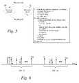
- FIG. 6illustrates an example of random timing and length of two measurement intervals
- FIG. 7illustrates a state diagram for the Receiver of a PM module
- FIG. 8illustrates a delay variation computation
- FIGS. 1-8 of the drawingslike numerals being used for like elements of the various drawings.
- FIG. 1illustrates a very simplified diagram of an environment in which the present invention could be used.
- a provider network 10links one or more locations of a customer network.
- the customer networkis shown having four locations (illustrated individually Locations A, B, C and D), each having its own local network 12 .
- Edge nodes 14provide a connection between the local area networks 12 and the provider nodes 16 of the provider network 10 .
- the provider network 10thus connects the various local networks 12 to form a wide area network.
- the provider network 10could support multiple customers, and it may use additional third party provider networks to provide the necessary connectivity.
- SLAservice level agreement
- jitterdelay variations
- the preferred embodiment of the present inventionuses a specific OAM frame (“PM frame”) for layer-2 (data link layer) performance monitoring.
- the PM frameis integrated in the OAM (Operations and Maintenance) for network management efficiency and simplicity.
- the PM frameis preferably in addition to other OAM frames currently developed in the 802.1ag series of drafts, specifically the CC (Connectivity Check), LB (Loop-Back), LT (Link Trace), and AIS (Alarm Indication Signal) frames. While the PM frame will be described as part of an Ethernet layer-2 environment, it could also be used in other layer-2 contexts, such as MPLS (Multi-protocol Label Switching).
- MPLSMulti-protocol Label Switching
- FIG. 2A general diagram for the preferred structure of a PM frame 20 is shown in FIG. 2 .
- the PM frame 20includes a Type field 24 , a Timestamp field 26 , and ID field 28 and a Padding field 30 . These fields can be located in either the header or payload of the frame, as appropriate.
- the Type field 24contains indicia to distinguish the PM frame 20 as being an OAM frame of type PM.
- the Type field 24could include a management level such as those defined in 802.1ag (eight levels from 0 to 7, for customers, providers and operators). In existing CFM (Connectivity Fault Management) 802.1ag, these two entries are referred to as “CFM” type and “ME level”. In addition, a version entry in this field could be added for future expansion.
- the Timestamp fieldstores one or more timestamps. Only one timestamp is necessary for one-way delay measurements, which are preferred. Multiple timestamps are supported.
- the time unitshould be capable of representing microseconds, and should be made expandable to represent nanoseconds so as to remain usable in the future.
- NTPNetwork Time Protocol
- the time formatcould follow for instance the existing standard NTP (Network Time Protocol), which uses 64 bits (in two parts: 32 bits for the seconds, and 32 bits for the fraction of a second).
- the ID field 26contains an interval number and a sequence number (or any monotonically increasing identification scheme) to allow frame discrimination by the processing functions, and correlation between senders and receivers. This is described in greater detail below.
- the Padding field 30allows the size of the frame 20 to be varied to simulate real data frames.
- categorizationthere are no specific fields in the PM frame 20 for categorization. It is expected that in Ethernet, categorization would be based on normal VLAN tags (C-tags, S-tags), on user priority bits and/or on drop precedence bits.
- PM frameswill be explained in connection with the operation of PM modules 31 , shown in greater detail in FIG. 3 .
- the functions of the PM modules 31could be implemented as routines in the bridge brains of any or all of the provider nodes 16 where performance measurements are necessary.
- the PM modules 31could also be implemented on the customer nodes 14 as well.
- Data from layer-1is sent and received over ports 32 , where the data is used to form frames. Ports 32 are coupled to a Sender 34 and a Receiver 36 .
- Sender 34 and Receiver 36are coupled to a Management Information Base (“MIB”) 38 .
- MIBManagement Information Base
- a NMS (Network Management System) interface 40couples MIB 36 to the NMS 42 (which is typically located in the Network Operations Center, or “NOC”, of the provider).
- the NMS interface 40receives the commands from the NMS 42 , updates the working variables used by the Sender 34 and Receiver 36 and may perform pre-computations, such as sorting and synthesizing the data, to reduce the NMS workload and to minimize the data volume exported to the NMS 42 .
- the Sender 34generates the flow of randomized PM frames 20 and logs the number of frames sent per interval.
- the Receiver 36intercepts PM frames 20 from other OAM frames and logs the measured delays.
- a Maintenance Association (“MA”) 48(also referred to as a Maintenance Entity Group, or “MEG” by ITU-T, to designate a group of point-to-point Maintenance Entities, or “ME”) is defined as a group of two or more nodes 14 or 16 , at least two of which contain a Maintenance End Point (“MEP”) 50 and may include zero or more Maintenance Intermediate Points (“MIP”s) 52 .
- MIPMaintenance Intermediate Points
- a MIPcould implement only the Receiver 36 and NMS interface 40 without the Sender 34 .
- a simplified MEP(such as one implemented in a residential gateway) could implement just the Sender 34 and a less complicated version of the NMS interface 40 , without the Receiver 36 .
- a one-way delay calculationcan be performed by sending one or more PM frames 20 from a source MEP 50 (individually referenced as MEP 50 s ) to a destination MEP 50 (individually referenced as MEP 50 d ).
- MEP 50 sa source MEP 50
- MEP 50 da destination MEP 50
- a timestampis entered in the Timestamp field 26 .
- the PM frame 20is recognized as a maintenance frame of type specified in the Type field 24 and is passed to the Receiver 36 .
- the delayis calculated by subtracting the time in the Timestamp field 26 from the current time from the clock associated with the destination MEP 50 d.
- an average one-way delay measurementcan be calculated.
- the PM framecan be timestamped at each MIP 52 in the path as well.
- a delaycan be calculated for each leg of the transmission.
- the timestampscan be provided by both the sender 34 and receiver 36 , with the difference in time subtracted from the delay.
- a two-way delay measurementcan be calculated by sending one or more PM frames 20 from the source MEP 50 s to the destination MEP 50 d , where it is timestamped by the destination MEP's Receiver 36 when received and the Sender 34 when sent back towards the source MEP 50 s . The time difference between the destination Sender 34 and Receiver 36 is subtracted from the delay measurement for greater accuracy. It should be noted that a two-way delay measurement negates the need for exact synchronization between the source and destination MEPs 50 .
- a one-way delay variation calculationcan be made by sending two or more PM frames 20 between the source MEP 50 s and the destination MEP 50 d .
- the difference in delays from source to destination for the two PM framesdefines a delay variation.
- the delay variationcan also be calculated over a stream of PM frames, preferably sent at randomized intervals with random padding sizes.
- delay variations for each leg of the pathcan be computed by timestamping the PM frame 20 at each MIP 52 . Because the delay between sender and receiver in each MIP will cancel out in the variation calculation, only a single timestamp is needed at each MIP 52 .
- a two-way delay variation calculationcan be performed by sending the PM frames from the source MEP 50 s to the destination MEP 50 d and back to the source MEP 50 s.
- Loss calculationscan be performed by sending a stream of PM frames from a source MEP 50 s to a destination 50 d . Frames that are not received in a certain period are counted as losses. Alternatively, a passive measurement of loss ratio can be computed by exchanging counter values of sent frames from the source MEP 50 s and received frames as the destination MEP 50 d.
- the NMS 42sets certain parameters for the source and destination MEP 50 .
- a mean ETH-PM rate(bit/s) is set that the total of ETH-PM traffic remains negligible, e.g. less than 0.1% or even 0.01% of the physical available bandwidth (on average).
- a loss threshold(seconds) set a duration (starting from the sending time) after which a frame is considered lost. Typically, the loss threshold would be on the order of a few minutes (example: 200 seconds).
- Minimum and maximum frame sizes (octets)are used by the frame random length computation. Usually, the Ethernet payload min and max range from 46-1500 octets (or 46-9000 octets for jumbo frames). These parameters are stored in the common working variables 44 of the PM module 31 .
- PM frames 20should enforce randomization and OAM traffic negligibility.
- delay-related framestypically a Poisson process
- some form of non-biased generatorshould be implemented for the sending schedule (typically a Poisson process)
- the frame length and paddingshould be randomized as well, to avoid incorrect measurements and optimization workarounds (node vendors could optimize their implementations for measurement frames if they were not randomized).
- a mechanismshould exist between a sending PM module 31 and a receiving PM module 31 to agree on a sending schedule (typically, sharing a random number generator seed and agreeing on an ID scheme), so that the receiving PM module 31 can decide whether a frame has been lost or not.
- Associated parametersshould be configurable in the NMS 42 .
- the store/export functionsshould use existing standards (SNMP, TMN, IPFIX, CORBA, XML, and so on), although beneath the standardized interfaces, optimized proprietary implementations can be used.
- the solutionensures better statistical significance of layer-2 measurements thanks to the required randomizations, is easier to manage for operators and providers since it is integrated in the OAM, does not require additional overlay equipment, and leverages the advantages of layer-2 monitoring: more accurate timestamping and deterministic paths. Accuracy improvements are due to the ability to timestamp closer to the physical layer, layer-1, so the arrival time of the last bit of a frame and the departure time of the first bit of a frame are better observed.
- PM frame 20A more detailed description of a PM frame is given below in Table 1. It should be noted that this is only an example of PM frame 20 using a current version of an Ethernet OAM frame as a basis; the future expansion to allow 802.1ah I-tags and B-tags and other header augmentation is assumed.
- Source-MEP indexis the concatenation of MA_ID and source MEP
- SeqNumis used as index in the individual frame MIB, not in the interval-based MIB (4): depending on NMS setting.
- the Ethertype fieldspecifies whether the frame is a data frame of a maintenance frame.
- the OpCode fieldspecifies the frame as a PM frame (and, if there are multiple PM frame types, this field can specify the type of PM frame).
- Timestamp, IID, SeqNum, Error and Padding fieldsare specific to the PM frame. In a given implementation, some fields may be omitted, or there may be different types of PM frames 20 with different fields.
- the Timestamp fieldcontains one or more timestamps provided by the Senders 34 of the PM modules 20 .
- the timestampis provided by the Sender 34 immediately prior to transmission of a PM frame 20 and the local clock is read by a Receiver 36 immediately upon reception of the PM frame 20 in order to have as little overhead delay as possible.
- the IID and SeqNumcomprise the ID field 28 .
- the IIDrepresents an interval, i.e., a stream of related PM frames 20 .
- the SeqNumis a sequence number unique for each PM frame 20 within an interval. Providing an IID and SeqNum in the PM frame can eliminate the need for setting up a session prior to sending PM frames. For example, if a destination MEP 50 starts receiving PM frames with a new IID, it can assume that a new performance measurement cycle is being invoked and begin taking measurements on that stream.
- the delay variation measurement moduleneeds to select certain frames in a stream, and a selection algorithm could rely on frame IDs (although the Min-to-Max selection function, which chooses the smallest delay—Min—and largest delay—Max—in an interval with the difference between Min and Max being the computed delay variation, is the most likely to be used).
- the loss measurement modulewhich must recognize frames as belonging to an agreed measurement interval: defining an interval based on frame IDs eliminates possible errors that can happen when defining intervals with time values (frames near the beginning or the end could be incorrectly counted in or out). For the possible future metric of Reordering (useful for real-time video transmission performance monitoring), the sequence number will also be necessary.
- the length of the IDat least 32 bits should be used, so as to be able to discriminate between more than 4 billions frames in a stream.
- the usual loss thresholdis a few minutes (say 200 seconds)
- a smallest Ethernet frame of 72 bytesincluding preamble and checksum, such as a cycle redundancy check, or “CRC”, or a frame check sequence, or “FCS”
- the maximum number of frameswould be almost 14 billion, only a small fraction of them being allowed to be OAM-PM (due to the requirement of negligible traffic). Therefore, a 16-bit ID could prove to be too limited.
- the Padding fieldis of variable size and content. Varying the size of PM frames within an interval provides the benefit of more accurate measurement, since real user data frames can have any arbitrary size, so OAM active measurement frames having variable size provides more realistic measurements. Varying the content, i.e., the sequence of “0”s and “1”s, also provides more accurate measurements, since certain hardware optimizations, such as data compression, could bias the measurement if it is made with OAM frames each with the same profile. Accordingly, the preferred embodiment uses a payload which is representative of real data frames and less subject to measurement bias.
- FIG. 5illustrates a state diagram of the Sender 34 .
- the Sender 34has two states: active 60 or stopped 62 . In the stopped state 60 , PM packets 20 are not being sent.
- the Sender 34transitions to the active state 62 .
- the Sender 34sends a stream of one or more PM packets 20 to a node associated with a destination MEP 50 d . If the measurement is a two way measurement, the destination MEP 50 d will send the PM packet back to the source MEP 50 s .
- FIG. 5shows pseudo-code for the operation of active state 62 . First, start and stop times for the interval are determined and an IID is assigned to the interval.
- the SeqNumis reset.
- the Sender 34starts sending PM frames 20 .
- a scheduled send timeis computed, preferably at random intervals.
- the frameis prepared with header information, IID, SeqNum and so on, such that the frame is ready for transmission, other than the timestamp.
- the timestampis inserted.
- SeqNumis incremented and the next PM frame, if any, is prepared by computing a scheduled send time and preparing the PM frame.
- the state diagram of FIG. 5is directed to a source MEP 50 s .
- An intermediate MIP 52if adding a timestamp, will only need to add the received timestamp and the sending timestamp to the PM frame 20 (this is typically performed by creating a new frame using information from the received PM frame 20 ), and send the new frame to the next MIP 52 or destination MEP 50 d.
- the Sendercan be activated or deactivated by the NMS 42 .
- the Sender 34decides for measurement intervals duration, one at a time, scheduled in the future. It maintains unique IIDs (Interval IDs), within the scope of the sender device.
- the pair ⁇ source MEP, IID ⁇defines uniquely an interval (within a rotation of the IID number) and is used as the main index in the storage tables. If multiple instances run in a MEP, they will share the same IID allocator, so as to guarantee unique per-MEP IIDs when an instance starts a new interval. Intervals may overlap when there are multiple instances.
- the durationshould be set to a “reasonable” value, not too long, not too short depending on the sending rate and the storage capacity of the Receivers. The duration can be randomized, but it is not required.
- next schedule time for sending the next PM frameis computed using a suitable algorithm.
- One such algorithmis described in draft - ietf - ippm - owdp -14 .txt , A One-way Active Measurement Protocol (OWAMP), IETF, December 2004. This algorithm is repeated below:
- the algorithmreturns a duration X, which is used to compute an instant T in the future, at which the frame will be sent.
- the randomized frameBefore this scheduled sending time T arrives, the randomized frame should be prepared in memory and be made ready to send, with the possible exception of the timestamp: it can be read at the last moment, or estimated accurately enough using T. Once the timestamp is set in the frame, the checksum can also be computed.
- the other fieldsshould be filled according to Table 1.
- the frame lengthis also randomized (uniformly between min and max length) and the padding bits are randomized too (uniformly between 0 and 1).
- any security-related frame construction procedureshould be performed at that point.
- the implementationshould take into account the fact that T could arrive soon, and have a ready-to-send frame at any time, maybe by building a few of them in advance.
- the Senderlogs the number of frames sent for each interval, for later NMS retrieval, and the loop restarts.
- FIG. 7illustrates a state diagram for the Receiver 36 .
- the Receiver 36can be in a stopped state 64 or an active state 66 . When it is deactivated, it ignores and discards the received PM frames. When it is activated, it first collects its local system clock, so as to have the most accurate arrival timestamp.
- An implementation optimizationcould consist in taking advantage of a clock module in the framer, which would obtain the time value as soon as the frame has entered the device and store in some efficient way (internal header, metadata, etc.). If such a module is not available, then the frame will experience more delays (port queue, port processing, bridge brain queue), and only then will be processed in the PM-specific portion of the Receiver. In that case, a systematic calibration error (estimation of the additional delays) should be included in the delay estimation, and be reported to the NMS 42 .
- the Delayis then computed and compared to the loss threshold. If the delay exceeds the loss threshold, the frame is deemed as lost and is ignored. Otherwise, a new entry is added in the MIB 38 , indexed by the triple ⁇ source MEP, IID, seq_num ⁇ .
- the SourceMEP identifieris being defined in 802.1ag, currently as a concatenation of the MD name, the MA name, and the 13-bit local MEPID. Four values are stored: the 3 fields describing priorities (DE, DP, UP), which can possibly be undefined depending on which tags were defined in the frame, and the Delay for that frame.
- the loss counter(actually, the number of received frames) is also maintained, indexed by the 5-uple ⁇ srcMEP, IID, DE, DP, UP ⁇ . Users may either want to see that level of detail, or only see the average per ⁇ srcMEP, IID ⁇ over all priorities.
- the list of values for DE, DP, UPincludes “undefined” for correct indexing: DE values are ⁇ 0,1,undef ⁇ , whereas DP and UP values are ⁇ 0,1,2,3,4,5,6,7,undef ⁇ . Besides, the index [undef] [undef] [undef] is invalid, and DE and DP are either both undefined or both defined.
- Table 2shows an example of a receiver in an arbitrary “MEP3”, showing just the entries corresponding to PM frames coming from a “MEP6” and its interval 27. In this example, all frames were received, except frame # 3 , whose seq_num is absent from that table.
- the DE/DP/UP indexingis not shown, for simplicity. The examples could correspond to a measurement case with all identical priorities.
- Table 3shows the counter used for loss ratio estimations, again without the ⁇ DE, DP, UP ⁇ priorities index.
- the NMS interface module 40could also implement “post-processing” functions, such as the DV (delay variation) computation, the MIB purge when it approaches saturation or after certain pre-defined delays, or more advanced functions, with a view to reducing the load on the NMS 42 as well as the amount of data to be exported.
- post-processingfunctions, such as the DV (delay variation) computation, the MIB purge when it approaches saturation or after certain pre-defined delays, or more advanced functions, with a view to reducing the load on the NMS 42 as well as the amount of data to be exported.
- the DV computationis shown in FIG. 8 .
- the DV computation functionruns a selection function, typically the Min-to-Max (search for the smallest and largest delays in the sample).
- the selection functionapplies to a measurement interval, defined by a source MEP, possibly on a per- ⁇ DE,DP,UP ⁇ basis. It may or may not need to be sure that the interval is over. If the function requires this, then a way to detect completion of a source MEP interval N is to observe arriving frames: if a frame belonging to a subsequent interval has arrived, its timestamp can be used to determine for sure, without signalling, an instant at which the destination MEP can not receive any more frames from interval N.
- a simpler selection functionsuch as “first-two” (selects the first two entries of a sample) does not need the interval to be over to start computation, since it only needs at least two entries.
- the purge functionmakes room in the MIB: it removes all the entries from an interval and replaces them with a summary (min, avg, median, max delays).
- An implementation possibilityis to combine the purged data with the received frame count and the DV (Delay Variation), as shown on Table 4:
- Receiver Interval-based MIB example DV(F: Min- srcMEP IID minDelay avgDelay maxDelay to-Max) count MEP6 27 21.5 ⁇ s 26.6 ⁇ s 38.7 ⁇ s 17.2 ⁇ s 574 MEP6 28 20.2 ⁇ s 25.9 ⁇ s 105.0 ⁇ s 84.8 ⁇ s 857
- the NMSwill perform the collection of Delay and Delay variation information, and the correlation to compute Losses:
- the loss rate estimationcan only be as accurate as the sample size: a rule of thumb is that about 20 or 30 events at least should be observed in order to make statistical conclusions. Therefore, a sample of size X can not detect losses smaller than 20/X. This is not a significant problem, since the goal is to notify the NMS 42 of potential problems that can lead to SLA non-conformance or even to a connectivity loss.
- the present inventionprovides significant advantages over the prior art. First, it can be easily implemented within the existing OAM framework, and can share hardware already used for the OAM functions. This makes the invention easy to manage for operators and providers. Second, the solution can use randomizations to ensure better statistical significance of layer-2 measurements. A layer-2 driver is likely to run much closer (if not directly in) the network card than a layer-3 processing module, thus obtaining better estimates of the real sending times Oust before the first bit is sent) and reception times Oust after the last bit is received). While these errors can be compensated by calibration, it is still best to minimize or avoid them altogether.
- the inventiondoes not need a signaling protocol whereby the nodes in the MA are informed of the parameters of the measurement session; the interval ID allows a source to initiate the equivalent of a session, without establishing an actual session, therefore the performance monitoring does not need a session protocol such as OWAMP or TWAMP.
- the interval IDsprovide the ability to adjust the frequency of the samples and size of their grouping, thereby improving the sample quality for better statistical significance.
- the Receiver functiondoes not need to change based on the specifics of the measurement session; its function remains the same whether the test is automatically initiated by the Sender or if it is on-demand (initiated by an operator), and whatever the randomization choices (such as padding variations).
- the performance measurementworks not only in a point-to-point context, but also in a multipoint context; in other words, the same receiver function can be used in multimetrics, where, for example, one source broadcasts/multicasts OAM frames to many destinations.
- Fifthsince it is integrated in the OAM, additional overlay equipment is not required.
- Sixthit leverages the advantages of layer-2 monitoring: more accurate timestamping and deterministic paths.
Landscapes
- Engineering & Computer Science (AREA)
- Computer Networks & Wireless Communication (AREA)
- Signal Processing (AREA)
- Mathematical Physics (AREA)
- Pure & Applied Mathematics (AREA)
- General Physics & Mathematics (AREA)
- Mathematical Analysis (AREA)
- Mathematical Optimization (AREA)
- Physics & Mathematics (AREA)
- Probability & Statistics with Applications (AREA)
- Algebra (AREA)
- Health & Medical Sciences (AREA)
- Cardiology (AREA)
- General Health & Medical Sciences (AREA)
- Environmental & Geological Engineering (AREA)
- Data Exchanges In Wide-Area Networks (AREA)
- Maintenance And Management Of Digital Transmission (AREA)
Abstract
Description
| TABLE 1 |
| PM Frame Fields |
| Parameter | Value | Index in MIB | Random |
| DA | 2 cases: | ||
| 1) multicast to all MA: reserved | |||
| multicast OAM address (with or | |||
| without embedded MA level) | |||
| 2) unicast (determined by dest | |||
| MEP) | |||
| SA | determined by source MEP | ||
| S-type (if any) | (802.1ad PB Provider Bridge) | ||
| S-tag: Drop Eligible | either set or randomized | yes (1) | maybe (4) |
| bit | |||
| S-tag: Drop | either set or randomized | yes (1) | maybe (4) |
| Precedence | |||
| S-tag: S-VLAN | determined by source MEP | ||
| C-type (if any) | (802.1Q): 0x8100 | ||
| C-tag: User Priority | either set or randomized | yes (1) | maybe (4) |
| C-tag: C-VLAN | determined by source MEP | ||
| Ethertype | (802.1ag CFM) | ||
| Version (5 bits) | 0 (same as CFM version) | ||
| MA level (3 bits) | determined by source MEP | ||
| OpCode (8 bits) | ETH-PM | ||
| MA_ID (one of 3 | determined by source MEP | ||
| types: (string, 2-octet | |||
| integer, RFC 2685 7- | |||
| octet VPNID), 1 TLV | |||
| per type); 11 octets at | |||
| least | |||
| source MEP (9-octet | determined by source MEP | yes (2) | |
| TLV) | |||
| TimeStamp (64 bits) | fetched from clock and set by | ||
| Sender at the last moment, read | |||
| by Receiver before anything else | |||
| IID (32 bits) | interval id (decided by Sender) | yes | |
| SeqNum (32 bits) | frame id in interval | yes (3) | |
| Error (16 bits) | scale and multiplier, smallest | ||
| representable value is 0.23 ns (2−32s), | |||
| similar to that proposed by | |||
| OWAMP | |||
| Padding: length and | yes | ||
| values, with security | |||
| considerations if any | |||
| (IZP) | |||
| Notes to Table 1: | |||
| (1): DE/DP/UP (Drop Eligible, Drop Precedence, User Priority) are used as index in the interval-based MIB, not in the individual frame MIB. | |||
| (2): the Source-MEP index is the concatenation of MA_ID and source MEP | |||
| (3): SeqNum is used as index in the individual frame MIB, not in the interval-based MIB | |||
| (4): depending on NMS setting. To resolve the DE/DP/UP fields choice in the S-tag and the C-tag, either a randomization or a set of specific values with NMS commands is allowed. | |||
- Algorithm S: Given a real positive number ‘mu’, produce an exponential random variate with mean ‘mu’.
- First, the constants
Q[k]=(ln 2)/(1!)+(ln 2)^2/(2!)+ . . . +(ln 2)^k/(k!), 1<=k<=11 - are computed in advance. The exact values which MUST be used by all implementations are given in the next section. This is necessary to insure that exactly the same pseudo-random sequences are produced by all implementations.
- First, the constants
- S1. [Get U and shift.] Generate a 32-bit uniform random binary fraction
U=(.b0b1b2. . . b31) [note the binary point]- Locate the first zero bit b_j, and shift off the leading (j+1) bits, setting U<-(.b_{j+1} . . . b31)
- Note: In the rare case that the zero has not been found, it is prescribed that the algorithm return (mu*32*ln2).
- S2. [Immediate acceptance?] If U<
ln 2, set X<-mu*(j*ln 2+U) and terminate the algorithm. (Note that Q[1]=ln 2.) - S3. [Minimize.] Find the least k>=2 such that U<Q[k]. Generate k new uniform random binary fractions U1, . . . ,Uk and set V<-min(U1, . . . ,Uk).
- S4. [Deliver the answer.] Set X<-mu*(j+V)*
ln 2. - To clarify, it can be noted that the limit of Q[k] is 1 when k increases indefinitely, and that the binary fraction notation (.b0 b1 . . . b31) means
- Algorithm S: Given a real positive number ‘mu’, produce an exponential random variate with mean ‘mu’.
- The eleven values of Q[k] are as follows (quote from draft-ietf-ippm-owdp-14.txt, referenced above):
- #1 0xB17217F8,
- #2 0xEEF193F7,
- #3 0xFD271862,
- #4 0xFF9D6DD0,
- #5 0xFFF4CFD0,
- #6 0xFFFEE819,
- #7 0xFFFFE7FF,
- #8 0xFFFFFE2B,
- #9 0xFFFFFFE0,
- #10 0xFFFFFFFE,
- #11 0xFFFFFFFF
- The eleven values of Q[k] are as follows (quote from draft-ietf-ippm-owdp-14.txt, referenced above):
| TABLE 2 |
| Receiver MIB example - Frame delay |
| srcMEP | IID | seq_num | |||
| MEP6 |
| 27 | 0 | 25.3 | ||
| MEP6 | ||||
| 27 | 1 | 29.2 | ||
| MEP6 | ||||
| 27 | 2 | 21.5 | ||
| MEP6 | ||||
| 27 | 4 | 33.2 | ||
| MEP6 | ||||
| 27 | 5 | 25.4 μs | ||
| . . . | . . . | . . . | . . . | |
| 27 | 574 | 38.7 μs | ||
| TABLE 3 |
| Received Okay example |
| srcMEP | rcvd_OK | |||
| MEP6 | ||||
| 27 | 574 | |||
| 28 | 857 | |||
| TABLE 4 |
| Receiver Interval-based MIB example |
| DV (F: Min- | ||||||
| srcMEP | IID | minDelay | avgDelay | maxDelay | to-Max) | count |
| MEP6 | 27 | 21.5 μs | 26.6 μs | 38.7 μs | 17.2 | 574 |
| MEP6 | 28 | 20.2 μs | 25.9 μs | 105.0 μs | 84.8 μs | 857 |
- MEP6-sender reports 575 frames sent in
interval 27 - MEP3-
receiver reports 574 frames received from MEP6 corresponding to MEP6'sinterval 27 - NMS can compute a loss rate estimate for MEP6-defined interval 27: (1-574/575)=0.00174=0.174%
- MEP6-sender reports 857 frames sent in
interval 28 - MEP3-receiver reports 857 frames received from MEP6 corresponding to MEP6's
interval 28 - NMS can compute a loss rate estimate for MEP6-defined interval 28: (1-857/857)=0.00000=0.000%
- MEP6-sender reports 575 frames sent in
Claims (16)
Priority Applications (4)
| Application Number | Priority Date | Filing Date | Title |
|---|---|---|---|
| US11/383,741US7733794B2 (en) | 2005-06-17 | 2006-05-16 | Performance monitoring of frame transmission in data network OAM protocols |
| AT06010797TATE442716T1 (en) | 2005-06-17 | 2006-05-26 | PERFORMANCE MONITORING FOR TRANSMITTING FRAMES IN AN OAM PROTOCOL DATA NETWORK |
| EP06010797AEP1734690B1 (en) | 2005-06-17 | 2006-05-26 | Performance monitoring of frame transmission in a data network utilising OAM protocols |
| DE602006009016TDE602006009016D1 (en) | 2005-06-17 | 2006-05-26 | Performance monitoring for the transmission of frames in an OAM protocol data network |
Applications Claiming Priority (2)
| Application Number | Priority Date | Filing Date | Title |
|---|---|---|---|
| US69149305P | 2005-06-17 | 2005-06-17 | |
| US11/383,741US7733794B2 (en) | 2005-06-17 | 2006-05-16 | Performance monitoring of frame transmission in data network OAM protocols |
Publications (2)
| Publication Number | Publication Date |
|---|---|
| US20060285501A1 US20060285501A1 (en) | 2006-12-21 |
| US7733794B2true US7733794B2 (en) | 2010-06-08 |
Family
ID=36950069
Family Applications (1)
| Application Number | Title | Priority Date | Filing Date |
|---|---|---|---|
| US11/383,741Expired - Fee RelatedUS7733794B2 (en) | 2005-06-17 | 2006-05-16 | Performance monitoring of frame transmission in data network OAM protocols |
Country Status (4)
| Country | Link |
|---|---|
| US (1) | US7733794B2 (en) |
| EP (1) | EP1734690B1 (en) |
| AT (1) | ATE442716T1 (en) |
| DE (1) | DE602006009016D1 (en) |
Cited By (10)
| Publication number | Priority date | Publication date | Assignee | Title |
|---|---|---|---|---|
| US20060007863A1 (en)* | 2002-09-05 | 2006-01-12 | Siamak Naghian | Signal propagation delay routing |
| US20100192002A1 (en)* | 2007-03-26 | 2010-07-29 | Yu Su | Method and apparatus of testing data communication performance of a network system |
| US20110010585A1 (en)* | 2009-07-09 | 2011-01-13 | Embarg Holdings Company, Llc | System and method for a testing vector and associated performance map |
| US20110194564A1 (en)* | 2010-02-05 | 2011-08-11 | Cisco Technology, Inc., A Corporation Of California | Distributing Ethernet Alarm Indication Signal Information to Multiple Virtual Local Area Networks |
| CN102307119A (en)* | 2011-08-18 | 2012-01-04 | 工业和信息化部电信传输研究所 | Method for discovering probe failure in Internet performance measurement system |
| US20120144409A1 (en)* | 2010-12-01 | 2012-06-07 | At&T Intellectual Property I, L.P. | Method and system for performance metric analysis of video assets |
| US8848563B2 (en) | 2012-06-12 | 2014-09-30 | Calix, Inc. | Systems and methods for measuring frame loss in multipoint networks |
| US8849965B2 (en) | 2011-10-19 | 2014-09-30 | Honeywell International Inc. | Wireless network performance monitoring |
| US8989032B2 (en) | 2012-06-12 | 2015-03-24 | Calix, Inc. | Systems and methods for measuring frame loss in multipoint networks |
| US10461886B2 (en) | 2017-10-16 | 2019-10-29 | Cisco Technology, Inc. | Transport layer identifying failure cause and mitigation for deterministic transport across multiple deterministic data links |
Families Citing this family (110)
| Publication number | Priority date | Publication date | Assignee | Title |
|---|---|---|---|---|
| US7715310B1 (en) | 2004-05-28 | 2010-05-11 | Cisco Technology, Inc. | L2VPN redundancy with ethernet access domain |
| US7643409B2 (en)* | 2004-08-25 | 2010-01-05 | Cisco Technology, Inc. | Computer network with point-to-point pseudowire redundancy |
| US8194656B2 (en) | 2005-04-28 | 2012-06-05 | Cisco Technology, Inc. | Metro ethernet network with scaled broadcast and service instance domains |
| US8213435B2 (en) | 2005-04-28 | 2012-07-03 | Cisco Technology, Inc. | Comprehensive model for VPLS |
| US9088669B2 (en) | 2005-04-28 | 2015-07-21 | Cisco Technology, Inc. | Scalable system and method for DSL subscriber traffic over an Ethernet network |
| US7835370B2 (en)* | 2005-04-28 | 2010-11-16 | Cisco Technology, Inc. | System and method for DSL subscriber identification over ethernet network |
| CN1859154B (en)* | 2005-05-08 | 2010-12-22 | 华为技术有限公司 | Performance managing method between household gateway and broad band remote access server |
| US8094663B2 (en) | 2005-05-31 | 2012-01-10 | Cisco Technology, Inc. | System and method for authentication of SP ethernet aggregation networks |
| US8175078B2 (en) | 2005-07-11 | 2012-05-08 | Cisco Technology, Inc. | Redundant pseudowires between Ethernet access domains |
| US7515542B2 (en)* | 2005-07-12 | 2009-04-07 | Cisco Technology, Inc. | Broadband access note with a virtual maintenance end point |
| US7889754B2 (en)* | 2005-07-12 | 2011-02-15 | Cisco Technology, Inc. | Address resolution mechanism for ethernet maintenance endpoints |
| US8169924B2 (en)* | 2005-08-01 | 2012-05-01 | Cisco Technology, Inc. | Optimal bridging over MPLS/IP through alignment of multicast and unicast paths |
| US7855950B2 (en)* | 2005-08-01 | 2010-12-21 | Cisco Technology, Inc. | Congruent forwarding paths for unicast and multicast traffic |
| KR100715673B1 (en)* | 2005-09-07 | 2007-05-09 | 한국전자통신연구원 | User Packet Processing Method Using Subscriber Identification Tag |
| US9088619B2 (en) | 2005-09-14 | 2015-07-21 | Cisco Technology, Inc. | Quality of service based on logical port identifier for broadband aggregation networks |
| US7788371B2 (en)* | 2006-03-20 | 2010-08-31 | Cisco Technology, Inc. | Exporting management information base data using IPFIX |
| US8488447B2 (en) | 2006-06-30 | 2013-07-16 | Centurylink Intellectual Property Llc | System and method for adjusting code speed in a transmission path during call set-up due to reduced transmission performance |
| US9094257B2 (en) | 2006-06-30 | 2015-07-28 | Centurylink Intellectual Property Llc | System and method for selecting a content delivery network |
| US8289965B2 (en) | 2006-10-19 | 2012-10-16 | Embarq Holdings Company, Llc | System and method for establishing a communications session with an end-user based on the state of a network connection |
| US8000318B2 (en) | 2006-06-30 | 2011-08-16 | Embarq Holdings Company, Llc | System and method for call routing based on transmission performance of a packet network |
| US8194643B2 (en) | 2006-10-19 | 2012-06-05 | Embarq Holdings Company, Llc | System and method for monitoring the connection of an end-user to a remote network |
| US7765294B2 (en) | 2006-06-30 | 2010-07-27 | Embarq Holdings Company, Llc | System and method for managing subscriber usage of a communications network |
| US7948909B2 (en) | 2006-06-30 | 2011-05-24 | Embarq Holdings Company, Llc | System and method for resetting counters counting network performance information at network communications devices on a packet network |
| US8717911B2 (en) | 2006-06-30 | 2014-05-06 | Centurylink Intellectual Property Llc | System and method for collecting network performance information |
| US8619600B2 (en) | 2006-08-22 | 2013-12-31 | Centurylink Intellectual Property Llc | System and method for establishing calls over a call path having best path metrics |
| US8064391B2 (en) | 2006-08-22 | 2011-11-22 | Embarq Holdings Company, Llc | System and method for monitoring and optimizing network performance to a wireless device |
| US7684332B2 (en) | 2006-08-22 | 2010-03-23 | Embarq Holdings Company, Llc | System and method for adjusting the window size of a TCP packet through network elements |
| US7889660B2 (en) | 2006-08-22 | 2011-02-15 | Embarq Holdings Company, Llc | System and method for synchronizing counters on an asynchronous packet communications network |
| US8238253B2 (en)* | 2006-08-22 | 2012-08-07 | Embarq Holdings Company, Llc | System and method for monitoring interlayer devices and optimizing network performance |
| US8144586B2 (en) | 2006-08-22 | 2012-03-27 | Embarq Holdings Company, Llc | System and method for controlling network bandwidth with a connection admission control engine |
| US8130793B2 (en) | 2006-08-22 | 2012-03-06 | Embarq Holdings Company, Llc | System and method for enabling reciprocal billing for different types of communications over a packet network |
| US8750158B2 (en) | 2006-08-22 | 2014-06-10 | Centurylink Intellectual Property Llc | System and method for differentiated billing |
| US8040811B2 (en) | 2006-08-22 | 2011-10-18 | Embarq Holdings Company, Llc | System and method for collecting and managing network performance information |
| US8102770B2 (en) | 2006-08-22 | 2012-01-24 | Embarq Holdings Company, LP | System and method for monitoring and optimizing network performance with vector performance tables and engines |
| US7808918B2 (en) | 2006-08-22 | 2010-10-05 | Embarq Holdings Company, Llc | System and method for dynamically shaping network traffic |
| US8407765B2 (en) | 2006-08-22 | 2013-03-26 | Centurylink Intellectual Property Llc | System and method for restricting access to network performance information tables |
| US8194555B2 (en) | 2006-08-22 | 2012-06-05 | Embarq Holdings Company, Llc | System and method for using distributed network performance information tables to manage network communications |
| US8743703B2 (en) | 2006-08-22 | 2014-06-03 | Centurylink Intellectual Property Llc | System and method for tracking application resource usage |
| US8189468B2 (en) | 2006-10-25 | 2012-05-29 | Embarq Holdings, Company, LLC | System and method for regulating messages between networks |
| US8224255B2 (en)* | 2006-08-22 | 2012-07-17 | Embarq Holdings Company, Llc | System and method for managing radio frequency windows |
| US8576722B2 (en) | 2006-08-22 | 2013-11-05 | Centurylink Intellectual Property Llc | System and method for modifying connectivity fault management packets |
| US9479341B2 (en) | 2006-08-22 | 2016-10-25 | Centurylink Intellectual Property Llc | System and method for initiating diagnostics on a packet network node |
| US7940735B2 (en)* | 2006-08-22 | 2011-05-10 | Embarq Holdings Company, Llc | System and method for selecting an access point |
| US8274905B2 (en) | 2006-08-22 | 2012-09-25 | Embarq Holdings Company, Llc | System and method for displaying a graph representative of network performance over a time period |
| US8228791B2 (en) | 2006-08-22 | 2012-07-24 | Embarq Holdings Company, Llc | System and method for routing communications between packet networks based on intercarrier agreements |
| US8098579B2 (en) | 2006-08-22 | 2012-01-17 | Embarq Holdings Company, LP | System and method for adjusting the window size of a TCP packet through remote network elements |
| US8015294B2 (en) | 2006-08-22 | 2011-09-06 | Embarq Holdings Company, LP | Pin-hole firewall for communicating data packets on a packet network |
| US8307065B2 (en) | 2006-08-22 | 2012-11-06 | Centurylink Intellectual Property Llc | System and method for remotely controlling network operators |
| US8537695B2 (en) | 2006-08-22 | 2013-09-17 | Centurylink Intellectual Property Llc | System and method for establishing a call being received by a trunk on a packet network |
| US8125897B2 (en) | 2006-08-22 | 2012-02-28 | Embarq Holdings Company Lp | System and method for monitoring and optimizing network performance with user datagram protocol network performance information packets |
| US8107366B2 (en) | 2006-08-22 | 2012-01-31 | Embarq Holdings Company, LP | System and method for using centralized network performance tables to manage network communications |
| US8531954B2 (en) | 2006-08-22 | 2013-09-10 | Centurylink Intellectual Property Llc | System and method for handling reservation requests with a connection admission control engine |
| US7843831B2 (en) | 2006-08-22 | 2010-11-30 | Embarq Holdings Company Llc | System and method for routing data on a packet network |
| US8144587B2 (en) | 2006-08-22 | 2012-03-27 | Embarq Holdings Company, Llc | System and method for load balancing network resources using a connection admission control engine |
| US8549405B2 (en) | 2006-08-22 | 2013-10-01 | Centurylink Intellectual Property Llc | System and method for displaying a graphical representation of a network to identify nodes and node segments on the network that are not operating normally |
| US8199653B2 (en) | 2006-08-22 | 2012-06-12 | Embarq Holdings Company, Llc | System and method for communicating network performance information over a packet network |
| US8223655B2 (en) | 2006-08-22 | 2012-07-17 | Embarq Holdings Company, Llc | System and method for provisioning resources of a packet network based on collected network performance information |
| KR100853184B1 (en)* | 2006-10-24 | 2008-08-20 | 한국전자통신연구원 | Apparatus and method for measuring frame loss of multicast service traffic |
| US7616568B2 (en)* | 2006-11-06 | 2009-11-10 | Ixia | Generic packet generation |
| US8416790B1 (en) | 2007-02-05 | 2013-04-09 | World Wide Packets, Inc. | Processing Ethernet packets associated with packet tunnels |
| US8416789B1 (en)* | 2007-02-05 | 2013-04-09 | World Wide Packets, Inc. | Multipoint packet forwarding using packet tunnels |
| US8804534B2 (en) | 2007-05-19 | 2014-08-12 | Cisco Technology, Inc. | Interworking between MPLS/IP and Ethernet OAM mechanisms |
| US20080298258A1 (en)* | 2007-05-30 | 2008-12-04 | Alcatel Lucent | Information transfer capability discovery apparatus and techniques |
| US8111692B2 (en) | 2007-05-31 | 2012-02-07 | Embarq Holdings Company Llc | System and method for modifying network traffic |
| US8531941B2 (en)* | 2007-07-13 | 2013-09-10 | Cisco Technology, Inc. | Intra-domain and inter-domain bridging over MPLS using MAC distribution via border gateway protocol |
| EP2034662A1 (en)* | 2007-07-20 | 2009-03-11 | Nokia Siemens Networks Oy | Self monitoring of managed entities in a telecommunication network |
| US8391148B1 (en)* | 2007-07-30 | 2013-03-05 | Rockstar Consortion USLP | Method and apparatus for Ethernet data compression |
| ES2705798T3 (en)* | 2007-08-01 | 2019-03-26 | Ericsson Telefon Ab L M | Provision of OAM based on GMPLS |
| US8077709B2 (en) | 2007-09-19 | 2011-12-13 | Cisco Technology, Inc. | Redundancy at a virtual provider edge node that faces a tunneling protocol core network for virtual private local area network (LAN) service (VPLS) |
| US7751450B2 (en)* | 2007-09-28 | 2010-07-06 | Verizon Patent And Licensing Inc. | Voice over internet protocol marker insertion |
| JP4986155B2 (en)* | 2007-10-15 | 2012-07-25 | 横河電機株式会社 | Communication quality diagnostic device |
| US7957295B2 (en) | 2007-11-02 | 2011-06-07 | Cisco Technology, Inc. | Ethernet performance monitoring |
| CN101447975B (en)* | 2007-11-26 | 2013-12-04 | 华为技术有限公司 | Method for processing Ethernet physical layer OAM overhead and device thereof |
| JP2009212863A (en)* | 2008-03-04 | 2009-09-17 | Nec Corp | Line status monitoring circuit, node, communication system, and failure occurrence determining method |
| JP2009212875A (en)* | 2008-03-05 | 2009-09-17 | Nec Corp | Communication device and operation management method used for the same |
| US8068425B2 (en) | 2008-04-09 | 2011-11-29 | Embarq Holdings Company, Llc | System and method for using network performance information to determine improved measures of path states |
| US8229705B1 (en)* | 2008-08-05 | 2012-07-24 | Marvell Israel (M.I.S.I.) Ltd. | Performance monitoring in computer networks |
| US8036116B2 (en)* | 2008-10-17 | 2011-10-11 | At & T Intellectual Property I, Lp | VoIP network element performance detection for IP NSEP special service |
| CN101420317B (en)* | 2008-11-21 | 2011-10-26 | 华为终端有限公司 | Restoring method, recording terminal, server and system for media file recording error |
| US9490894B2 (en)* | 2008-12-08 | 2016-11-08 | Ciena Corporation | Coherent probe and optical service channel systems and methods for optical networks |
| US8125920B2 (en) | 2009-03-04 | 2012-02-28 | Cisco Technology, Inc. | System and method for exporting structured data in a network environment |
| JP5287481B2 (en)* | 2009-05-01 | 2013-09-11 | 日立電線株式会社 | Network relay device, network, and network maintenance operation method |
| CN102082697A (en) | 2009-11-27 | 2011-06-01 | 华为技术有限公司 | Communication path asymmetric time delay measuring method, device and system |
| US8724487B1 (en) | 2010-02-15 | 2014-05-13 | Cisco Technology, Inc. | System and method for synchronized reporting in a network environment |
| US8830841B1 (en) | 2010-03-23 | 2014-09-09 | Marvell Israel (M.I.S.L) Ltd. | Operations, administration, and maintenance (OAM) processing engine |
| EP2953296B1 (en)* | 2010-11-18 | 2017-04-19 | Telefonaktiebolaget LM Ericsson (publ) | Systems and methods for measuring available capacity and tight link capacity of ip paths from a single endpoint |
| CN103380595B (en)* | 2011-02-21 | 2016-09-07 | 三菱电机株式会社 | Communication device and communication method |
| US8650285B1 (en) | 2011-03-22 | 2014-02-11 | Cisco Technology, Inc. | Prevention of looping and duplicate frame delivery in a network environment |
| CN102158683B (en)* | 2011-04-25 | 2015-08-12 | 中兴通讯股份有限公司 | The method of testing of video delay in video conference and computer |
| CA2840980A1 (en)* | 2011-07-04 | 2013-01-10 | Nec Corporation | Transmission system, transmission device, packet loss ratio measurement method, and packet loss ratio measurement program |
| US9253062B2 (en)* | 2011-12-23 | 2016-02-02 | Ixia | Byte by byte received data integrity check |
| EP2677690A1 (en)* | 2012-06-21 | 2013-12-25 | ABB Research Ltd. | Determining the network topology of a communication network |
| US8711708B2 (en)* | 2012-07-24 | 2014-04-29 | Accedian Networks Inc. | Automatic setup of reflector instances |
| US9960982B2 (en) | 2012-07-24 | 2018-05-01 | Accedian Networks Inc. | Multi-hop reflector sessions |
| JP5578207B2 (en)* | 2012-08-09 | 2014-08-27 | 株式会社デンソー | Communication load judgment device |
| US9306830B2 (en)* | 2013-01-30 | 2016-04-05 | Accedian Networks Inc. | Layer-3 performance monitoring sectionalization |
| EP2957069B1 (en) | 2013-02-14 | 2017-02-01 | Telefonaktiebolaget LM Ericsson (publ) | Method and network entity for evaluating a link between a first network node and a second network node |
| CN103152202B (en)* | 2013-03-13 | 2016-03-30 | 华为技术有限公司 | Parameter deployment, communication node and communication network |
| US9001687B2 (en)* | 2013-04-05 | 2015-04-07 | Telefonaktiebolaget L M Ericsson (Publ) | Packet interception and timestamping for error estimation in active measurement protocols |
| US20150029871A1 (en)* | 2013-07-24 | 2015-01-29 | Cisco Technology, Inc. | Service level agreement validation via service traffic sample-and-replay |
| US9641416B2 (en)* | 2014-04-18 | 2017-05-02 | Cisco Technology, Inc. | Operations analysis of packet groups identified based on timestamps |
| US9503344B2 (en)* | 2014-07-25 | 2016-11-22 | Telefonaktiebolaget L M Ericsson (Publ) | Data path performance measurement using network traffic in a software defined network |
| US9537741B2 (en)* | 2014-07-25 | 2017-01-03 | Telefonaktiebolaget L M Ericsson (Publ) | Data path performance measurement using test messages in a software defined network |
| US9660725B2 (en)* | 2014-07-30 | 2017-05-23 | Cisco Technology, Inc. | Identifier announcement and detection scheme for PoE fixtures |
| EP3979566A1 (en)* | 2015-12-09 | 2022-04-06 | Huawei Technologies Co., Ltd. | System, method and nodes for performance measurement in segment routing network |
| US10644985B1 (en) | 2016-09-29 | 2020-05-05 | Juniper Networks, Inc. | Device-contained data plane validation |
| CN109309544B (en)* | 2018-08-13 | 2020-05-12 | 烽火通信科技股份有限公司 | Method and system for improving timestamp precision in time delay measurement |
| US10917340B2 (en) | 2018-09-11 | 2021-02-09 | Cisco Technology, Inc. | In-situ passive performance measurement in a network environment |
| EP3693859B1 (en) | 2019-02-06 | 2022-04-27 | ADVA Optical Networking SE | Method and system of latency assessment in a packet data network |
| CN109873822B (en)* | 2019-02-22 | 2020-06-23 | 武汉大学 | Device and method for detecting firewall rule change based on Beidou subnanosecond high-precision time service |
Citations (8)
| Publication number | Priority date | Publication date | Assignee | Title |
|---|---|---|---|---|
| EP0195636A2 (en) | 1985-03-19 | 1986-09-24 | Citizen Watch Co. Ltd. | Wristwatch with pressure sensor |
| US5450394A (en)* | 1994-03-10 | 1995-09-12 | Northern Telecom Limited | Delay monitoring of telecommunication networks |
| US5764626A (en)* | 1995-11-17 | 1998-06-09 | Telecommunications Techniques Corporation | Rate-matched cell identification and modification, replacement, or insertion for test and measurement of ATM network virtual connections |
| EP0915635A1 (en) | 1997-11-07 | 1999-05-12 | Nortel Networks Corporation | Delay monitoring of telecommunication networks |
| US6058102A (en)* | 1997-11-07 | 2000-05-02 | Visual Networks Technologies, Inc. | Method and apparatus for performing service level analysis of communications network performance metrics |
| US6215772B1 (en) | 1997-11-26 | 2001-04-10 | International Business Machines Corporation | Dynamic parameter estimation for efficient transport of HPR data on IP |
| WO2002033893A2 (en) | 2000-10-17 | 2002-04-25 | Routescience Technologies, Inc. | Method and apparatus for communicating data within measurement traffic |
| US20050099949A1 (en)* | 2003-11-10 | 2005-05-12 | Nortel Networks Limited | Ethernet OAM domains and ethernet OAM frame format |
- 2006
- 2006-05-16USUS11/383,741patent/US7733794B2/ennot_activeExpired - Fee Related
- 2006-05-26DEDE602006009016Tpatent/DE602006009016D1/enactiveActive
- 2006-05-26ATAT06010797Tpatent/ATE442716T1/ennot_activeIP Right Cessation
- 2006-05-26EPEP06010797Apatent/EP1734690B1/ennot_activeNot-in-force
Patent Citations (8)
| Publication number | Priority date | Publication date | Assignee | Title |
|---|---|---|---|---|
| EP0195636A2 (en) | 1985-03-19 | 1986-09-24 | Citizen Watch Co. Ltd. | Wristwatch with pressure sensor |
| US5450394A (en)* | 1994-03-10 | 1995-09-12 | Northern Telecom Limited | Delay monitoring of telecommunication networks |
| US5764626A (en)* | 1995-11-17 | 1998-06-09 | Telecommunications Techniques Corporation | Rate-matched cell identification and modification, replacement, or insertion for test and measurement of ATM network virtual connections |
| EP0915635A1 (en) | 1997-11-07 | 1999-05-12 | Nortel Networks Corporation | Delay monitoring of telecommunication networks |
| US6058102A (en)* | 1997-11-07 | 2000-05-02 | Visual Networks Technologies, Inc. | Method and apparatus for performing service level analysis of communications network performance metrics |
| US6215772B1 (en) | 1997-11-26 | 2001-04-10 | International Business Machines Corporation | Dynamic parameter estimation for efficient transport of HPR data on IP |
| WO2002033893A2 (en) | 2000-10-17 | 2002-04-25 | Routescience Technologies, Inc. | Method and apparatus for communicating data within measurement traffic |
| US20050099949A1 (en)* | 2003-11-10 | 2005-05-12 | Nortel Networks Limited | Ethernet OAM domains and ethernet OAM frame format |
Non-Patent Citations (3)
| Title |
|---|
| International Telecommunication Union, "ITU-T Recommendation I.610 Series I: Integrated Services, Digital Network Maintenance Principles", International Telecommunication Union, Feb. 1999. |
| International Telecommunication Union, "ITU-T Recommendation O.191 Series O: Specifications of Measuring Equipment-Equipment for the measurement of digital and analogue/digital parameters", International Telecommunication Union, Feb. 2000. |
| Sato, Naoshi, Okamoto, Tsukas and Yokio, Tadahiro, "Performance Monitoring Method Using OAM Cells in B-ISDN", ICC '91, 1991, IEEE, 264-269, US. |
Cited By (17)
| Publication number | Priority date | Publication date | Assignee | Title |
|---|---|---|---|---|
| US20060007863A1 (en)* | 2002-09-05 | 2006-01-12 | Siamak Naghian | Signal propagation delay routing |
| US8072906B2 (en)* | 2002-09-05 | 2011-12-06 | Intellectual Ventures I Llc | Signal propagation delay routing |
| US20100192002A1 (en)* | 2007-03-26 | 2010-07-29 | Yu Su | Method and apparatus of testing data communication performance of a network system |
| US20110010585A1 (en)* | 2009-07-09 | 2011-01-13 | Embarg Holdings Company, Llc | System and method for a testing vector and associated performance map |
| US9210050B2 (en)* | 2009-07-09 | 2015-12-08 | Centurylink Intellectual Property Llc | System and method for a testing vector and associated performance map |
| US8547832B2 (en)* | 2010-02-05 | 2013-10-01 | Cisco Technology, Inc. | Distributing ethernet alarm indication signal information to multiple virtual local area networks |
| US20110194564A1 (en)* | 2010-02-05 | 2011-08-11 | Cisco Technology, Inc., A Corporation Of California | Distributing Ethernet Alarm Indication Signal Information to Multiple Virtual Local Area Networks |
| US20120144409A1 (en)* | 2010-12-01 | 2012-06-07 | At&T Intellectual Property I, L.P. | Method and system for performance metric analysis of video assets |
| US8332900B2 (en)* | 2010-12-01 | 2012-12-11 | At&T Intellectual Property I, L.P. | Method and system for performance metric analysis of video assets |
| US8863211B2 (en) | 2010-12-01 | 2014-10-14 | At&T Intellectual Property I, L.P. | Method and system for performance metric analysis of video assets |
| US10320504B2 (en) | 2010-12-01 | 2019-06-11 | At&T Intellectual Property I, L.P. | Method and system for performance metric analysis of video assets |
| CN102307119A (en)* | 2011-08-18 | 2012-01-04 | 工业和信息化部电信传输研究所 | Method for discovering probe failure in Internet performance measurement system |
| CN102307119B (en)* | 2011-08-18 | 2013-10-16 | 工业和信息化部电信传输研究所 | Method for discovering probe failure in Internet performance measurement system |
| US8849965B2 (en) | 2011-10-19 | 2014-09-30 | Honeywell International Inc. | Wireless network performance monitoring |
| US8848563B2 (en) | 2012-06-12 | 2014-09-30 | Calix, Inc. | Systems and methods for measuring frame loss in multipoint networks |
| US8989032B2 (en) | 2012-06-12 | 2015-03-24 | Calix, Inc. | Systems and methods for measuring frame loss in multipoint networks |
| US10461886B2 (en) | 2017-10-16 | 2019-10-29 | Cisco Technology, Inc. | Transport layer identifying failure cause and mitigation for deterministic transport across multiple deterministic data links |
Also Published As
| Publication number | Publication date |
|---|---|
| US20060285501A1 (en) | 2006-12-21 |
| EP1734690A1 (en) | 2006-12-20 |
| DE602006009016D1 (en) | 2009-10-22 |
| ATE442716T1 (en) | 2009-09-15 |
| EP1734690B1 (en) | 2009-09-09 |
Similar Documents
| Publication | Publication Date | Title |
|---|---|---|
| US7733794B2 (en) | Performance monitoring of frame transmission in data network OAM protocols | |
| US8045475B2 (en) | Method and apparatus for providing availability metrics for measurement and management of ethernet services | |
| CN111602370B (en) | In-band telemetry using limited extra bytes | |
| US6643612B1 (en) | Mechanism and protocol for per connection based service level agreement measurement | |
| KR101475347B1 (en) | Measurement of data loss in a communication network | |
| US7292537B2 (en) | Measurement architecture to obtain per-hop one-way packet loss and delay in multi-class service networks | |
| US8208389B2 (en) | Methods and apparatus for improved determination of network metrics | |
| US8953456B2 (en) | Ethernet OAM performance management | |
| KR101459252B1 (en) | Traceroute_delay diagnostic command | |
| US20050099954A1 (en) | Ethernet OAM network topography discovery | |
| US20050099949A1 (en) | Ethernet OAM domains and ethernet OAM frame format | |
| US20030023710A1 (en) | Network metric system | |
| CN100550786C (en) | In data network operation and maintenance agreement to the method for performance monitoring of frame transmission | |
| Chen et al. | Internet performance monitoring | |
| CN100382517C (en) | Network service quality testing method and system | |
| US20080019283A1 (en) | Performance Measurement in a Packet Transmission Network | |
| US11121938B2 (en) | Performance measurement in a packet-switched communication network | |
| Ðerić et al. | Towards understanding the performance of traffic policing in programmable hardware switches | |
| WO2014013303A1 (en) | Network service testing | |
| CN113973070B (en) | An information acquisition method, device and testing equipment | |
| Matta et al. | End-to-end voice over IP quality of service estimation through router queuing delay monitoring | |
| Lindh | Performance monitoring in communication networks | |
| CN119892695A (en) | Time delay measurement method, time delay measurement device, forwarding node and storage medium | |
| Tychon | Evaluate Network Performance with Cisco IOS® Service Assurance Agent | |
| WO2002095609A1 (en) | Network metric system |
Legal Events
| Date | Code | Title | Description |
|---|---|---|---|
| AS | Assignment | Owner name:ALCATEL,FRANCE Free format text:ASSIGNMENT OF ASSIGNORS INTEREST;ASSIGNOR:DAMM, GERARD;REEL/FRAME:018383/0522 Effective date:20060515 Owner name:ALCATEL, FRANCE Free format text:ASSIGNMENT OF ASSIGNORS INTEREST;ASSIGNOR:DAMM, GERARD;REEL/FRAME:018383/0522 Effective date:20060515 | |
| FEPP | Fee payment procedure | Free format text:PAYOR NUMBER ASSIGNED (ORIGINAL EVENT CODE: ASPN); ENTITY STATUS OF PATENT OWNER: LARGE ENTITY | |
| AS | Assignment | Owner name:ALCATEL LUCENT,FRANCE Free format text:CHANGE OF NAME;ASSIGNOR:ALCATEL;REEL/FRAME:024234/0945 Effective date:20061130 | |
| STCF | Information on status: patent grant | Free format text:PATENTED CASE | |
| FPAY | Fee payment | Year of fee payment:4 | |
| AS | Assignment | Owner name:PROVENANCE ASSET GROUP LLC, CONNECTICUT Free format text:ASSIGNMENT OF ASSIGNORS INTEREST;ASSIGNORS:NOKIA TECHNOLOGIES OY;NOKIA SOLUTIONS AND NETWORKS BV;ALCATEL LUCENT SAS;REEL/FRAME:043877/0001 Effective date:20170912 Owner name:NOKIA USA INC., CALIFORNIA Free format text:SECURITY INTEREST;ASSIGNORS:PROVENANCE ASSET GROUP HOLDINGS, LLC;PROVENANCE ASSET GROUP LLC;REEL/FRAME:043879/0001 Effective date:20170913 Owner name:CORTLAND CAPITAL MARKET SERVICES, LLC, ILLINOIS Free format text:SECURITY INTEREST;ASSIGNORS:PROVENANCE ASSET GROUP HOLDINGS, LLC;PROVENANCE ASSET GROUP, LLC;REEL/FRAME:043967/0001 Effective date:20170913 | |
| MAFP | Maintenance fee payment | Free format text:PAYMENT OF MAINTENANCE FEE, 8TH YEAR, LARGE ENTITY (ORIGINAL EVENT CODE: M1552) Year of fee payment:8 | |
| AS | Assignment | Owner name:NOKIA US HOLDINGS INC., NEW JERSEY Free format text:ASSIGNMENT AND ASSUMPTION AGREEMENT;ASSIGNOR:NOKIA USA INC.;REEL/FRAME:048370/0682 Effective date:20181220 | |
| AS | Assignment | Owner name:PROVENANCE ASSET GROUP LLC, CONNECTICUT Free format text:RELEASE BY SECURED PARTY;ASSIGNOR:CORTLAND CAPITAL MARKETS SERVICES LLC;REEL/FRAME:058983/0104 Effective date:20211101 Owner name:PROVENANCE ASSET GROUP HOLDINGS LLC, CONNECTICUT Free format text:RELEASE BY SECURED PARTY;ASSIGNOR:CORTLAND CAPITAL MARKETS SERVICES LLC;REEL/FRAME:058983/0104 Effective date:20211101 Owner name:PROVENANCE ASSET GROUP LLC, CONNECTICUT Free format text:RELEASE BY SECURED PARTY;ASSIGNOR:NOKIA US HOLDINGS INC.;REEL/FRAME:058363/0723 Effective date:20211129 Owner name:PROVENANCE ASSET GROUP HOLDINGS LLC, CONNECTICUT Free format text:RELEASE BY SECURED PARTY;ASSIGNOR:NOKIA US HOLDINGS INC.;REEL/FRAME:058363/0723 Effective date:20211129 | |
| AS | Assignment | Owner name:RPX CORPORATION, CALIFORNIA Free format text:ASSIGNMENT OF ASSIGNORS INTEREST;ASSIGNOR:PROVENANCE ASSET GROUP LLC;REEL/FRAME:059352/0001 Effective date:20211129 | |
| FEPP | Fee payment procedure | Free format text:MAINTENANCE FEE REMINDER MAILED (ORIGINAL EVENT CODE: REM.); ENTITY STATUS OF PATENT OWNER: LARGE ENTITY | |
| LAPS | Lapse for failure to pay maintenance fees | Free format text:PATENT EXPIRED FOR FAILURE TO PAY MAINTENANCE FEES (ORIGINAL EVENT CODE: EXP.); ENTITY STATUS OF PATENT OWNER: LARGE ENTITY | |
| STCH | Information on status: patent discontinuation | Free format text:PATENT EXPIRED DUE TO NONPAYMENT OF MAINTENANCE FEES UNDER 37 CFR 1.362 | |
| FP | Lapsed due to failure to pay maintenance fee | Effective date:20220608 |