US7733605B2 - Magnetic recording disk having a transition zone - Google Patents
Magnetic recording disk having a transition zoneDownload PDFInfo
- Publication number
- US7733605B2 US7733605B2US11/605,762US60576206AUS7733605B2US 7733605 B2US7733605 B2US 7733605B2US 60576206 AUS60576206 AUS 60576206AUS 7733605 B2US7733605 B2US 7733605B2
- Authority
- US
- United States
- Prior art keywords
- disk
- zone
- head
- slider
- data
- Prior art date
- Legal status (The legal status is an assumption and is not a legal conclusion. Google has not performed a legal analysis and makes no representation as to the accuracy of the status listed.)
- Expired - Fee Related, expires
Links
- 230000007704transitionEffects0.000titleclaimsabstractdescription39
- 230000005291magnetic effectEffects0.000titleabstractdescription50
- 239000000758substrateSubstances0.000claimsdescription35
- 238000000034methodMethods0.000claimsdescription26
- 230000008021depositionEffects0.000claims1
- 239000000725suspensionSubstances0.000description14
- 230000007246mechanismEffects0.000description7
- 239000011521glassSubstances0.000description6
- 238000005516engineering processMethods0.000description5
- 230000001939inductive effectEffects0.000description5
- 230000015654memoryEffects0.000description5
- VYPSYNLAJGMNEJ-UHFFFAOYSA-NSilicium dioxideChemical compoundO=[Si]=OVYPSYNLAJGMNEJ-UHFFFAOYSA-N0.000description4
- 230000000694effectsEffects0.000description4
- 229910001092metal group alloyInorganic materials0.000description4
- 230000008569processEffects0.000description4
- SNAAJJQQZSMGQD-UHFFFAOYSA-Naluminum magnesiumChemical compound[Mg].[Al]SNAAJJQQZSMGQD-UHFFFAOYSA-N0.000description3
- 239000000463materialSubstances0.000description3
- 230000010355oscillationEffects0.000description3
- 230000005355Hall effectEffects0.000description2
- 230000009471actionEffects0.000description2
- 239000005354aluminosilicate glassSubstances0.000description2
- 239000005388borosilicate glassSubstances0.000description2
- 239000000919ceramicSubstances0.000description2
- 229910003460diamondInorganic materials0.000description2
- 239000010432diamondSubstances0.000description2
- 238000004049embossingMethods0.000description2
- 239000000314lubricantSubstances0.000description2
- 229910052751metalInorganic materials0.000description2
- 239000002184metalSubstances0.000description2
- 238000011022operating instructionMethods0.000description2
- 229920000642polymerPolymers0.000description2
- 230000001681protective effectEffects0.000description2
- 230000002829reductive effectEffects0.000description2
- 230000035945sensitivityEffects0.000description2
- 239000000377silicon dioxideSubstances0.000description2
- 230000020347spindle assemblyEffects0.000description2
- OKTJSMMVPCPJKN-UHFFFAOYSA-NCarbonChemical compound[C]OKTJSMMVPCPJKN-UHFFFAOYSA-N0.000description1
- 230000005680Thomson effectEffects0.000description1
- 238000005299abrasionMethods0.000description1
- 239000003082abrasive agentSubstances0.000description1
- 230000002411adverseEffects0.000description1
- 230000004075alterationEffects0.000description1
- 230000015572biosynthetic processEffects0.000description1
- 229910052799carbonInorganic materials0.000description1
- 230000015556catabolic processEffects0.000description1
- 230000008859changeEffects0.000description1
- 238000004140cleaningMethods0.000description1
- 239000011248coating agentSubstances0.000description1
- 238000000576coating methodMethods0.000description1
- 238000004590computer programMethods0.000description1
- 238000009833condensationMethods0.000description1
- 230000005494condensationEffects0.000description1
- 238000011109contaminationMethods0.000description1
- 238000005260corrosionMethods0.000description1
- 230000007797corrosionEffects0.000description1
- 230000008878couplingEffects0.000description1
- 238000010168coupling processMethods0.000description1
- 238000005859coupling reactionMethods0.000description1
- 238000013500data storageMethods0.000description1
- 230000003247decreasing effectEffects0.000description1
- 238000006731degradation reactionMethods0.000description1
- 230000003292diminished effectEffects0.000description1
- 238000006073displacement reactionMethods0.000description1
- 238000000407epitaxyMethods0.000description1
- 230000001747exhibiting effectEffects0.000description1
- 230000006870functionEffects0.000description1
- 230000014509gene expressionEffects0.000description1
- 230000006872improvementEffects0.000description1
- 230000000670limiting effectEffects0.000description1
- 239000000696magnetic materialSubstances0.000description1
- 239000011159matrix materialSubstances0.000description1
- 230000000116mitigating effectEffects0.000description1
- 230000004048modificationEffects0.000description1
- 238000012986modificationMethods0.000description1
- 238000010943off-gassingMethods0.000description1
- 230000003287optical effectEffects0.000description1
- 239000002245particleSubstances0.000description1
- 238000000059patterningMethods0.000description1
- 230000010287polarizationEffects0.000description1
- 230000004044responseEffects0.000description1
- 238000007790scrapingMethods0.000description1
- 239000002002slurrySubstances0.000description1
- 230000003068static effectEffects0.000description1
- 230000000007visual effectEffects0.000description1
Images


Classifications
- G—PHYSICS
- G11—INFORMATION STORAGE
- G11B—INFORMATION STORAGE BASED ON RELATIVE MOVEMENT BETWEEN RECORD CARRIER AND TRANSDUCER
- G11B5/00—Recording by magnetisation or demagnetisation of a record carrier; Reproducing by magnetic means; Record carriers therefor
- G11B5/012—Recording on, or reproducing or erasing from, magnetic disks
- B—PERFORMING OPERATIONS; TRANSPORTING
- B82—NANOTECHNOLOGY
- B82Y—SPECIFIC USES OR APPLICATIONS OF NANOSTRUCTURES; MEASUREMENT OR ANALYSIS OF NANOSTRUCTURES; MANUFACTURE OR TREATMENT OF NANOSTRUCTURES
- B82Y10/00—Nanotechnology for information processing, storage or transmission, e.g. quantum computing or single electron logic
- G—PHYSICS
- G11—INFORMATION STORAGE
- G11B—INFORMATION STORAGE BASED ON RELATIVE MOVEMENT BETWEEN RECORD CARRIER AND TRANSDUCER
- G11B5/00—Recording by magnetisation or demagnetisation of a record carrier; Reproducing by magnetic means; Record carriers therefor
- G11B5/74—Record carriers characterised by the form, e.g. sheet shaped to wrap around a drum
- G11B5/743—Patterned record carriers, wherein the magnetic recording layer is patterned into magnetic isolated data islands, e.g. discrete tracks
- G—PHYSICS
- G11—INFORMATION STORAGE
- G11B—INFORMATION STORAGE BASED ON RELATIVE MOVEMENT BETWEEN RECORD CARRIER AND TRANSDUCER
- G11B5/00—Recording by magnetisation or demagnetisation of a record carrier; Reproducing by magnetic means; Record carriers therefor
- G11B5/74—Record carriers characterised by the form, e.g. sheet shaped to wrap around a drum
- G11B5/82—Disk carriers
- G—PHYSICS
- G11—INFORMATION STORAGE
- G11B—INFORMATION STORAGE BASED ON RELATIVE MOVEMENT BETWEEN RECORD CARRIER AND TRANSDUCER
- G11B5/00—Recording by magnetisation or demagnetisation of a record carrier; Reproducing by magnetic means; Record carriers therefor
- G11B2005/0002—Special dispositions or recording techniques
- G11B2005/0005—Arrangements, methods or circuits
- G11B2005/001—Controlling recording characteristics of record carriers or transducing characteristics of transducers by means not being part of their structure
Definitions
- Embodiments of the inventionrelate to the field of disk drives and, more particularly, to disks used in disk drive systems.
- the read/write head elementis typically a part of or coupled to a larger body that flies over the disk and is typically referred to as a “slider.”
- the sliderhas a lower surface referred to as an air bearing surface (ABS).
- ABSair bearing surface
- the ABSgenerally generates a positive air pressure.
- the slider bodyis attached to a suspension via a head gimbal assembly that biases the slider body towards the disk.
- the net effect of the ABS and the suspensionis to cause the slider, and coupled head, to fly at the desired height when the disk is at full speed.
- the net effectalso causes the slider to be in contact with the disk surface, when the disk is at rest, in contact-start-stop (CSS) disk drive systems.
- This contact between the slider and the diskoccurs in an area when the drive is turned on and off, and is known as a CSS zone.
- Another type of disk drive systemreferred to as load/unload disk drive system, parks the slider (more particularly a suspension arm on which the slider is secured) on a ramp, not the disk surface, when the drive is turned off.
- the headIn both types of disk drive systems, the head is idle and flies over a data zone while the disk is rotating awaiting instruction during a significant portion of the time in operation. As the flying height of the read/write head is reduced in the effort to increase recording densities, the frequency and likelihood of intermittent contact with the disk increases during drive operations. Such intermittent contact may cause the head to fly unstably and result in erroneous read back of data. In the worst-case scenario, if the impact of a hit is too severe, it may cause a head crash and damage the head and/or disk. Since the disk rotates very fast during normal operation of the drive, a concern is that the head should not undesirably contact the disk.
- reducing the fly height of a head in the data zoneincreases the possibility of the slider inadvertently contacting a landing zone feature (e.g., a CSS zone laser bump) or a disk surface during load/unload operations.
- a landing zone featuree.g., a CSS zone laser bump
- the height of laser bumps on a CSS zoneis lower than the fly height of a head over a data zone to avoid contact with the laser bumps while parking.
- lowering the bump heightmay increase the amount of stiction high enough to cause damage to the slider and/or disk surface.
- the air bearing supporting the fly height of the slideris disturbed and is eventually diminished as the slider transitions away from the data zone onto a landing zone feature, increasing the possibility of inadvertent contacts.
- U.S. Pat. No. 6,075,683discloses a disk drive having a slider exhibiting two fly heights, one for writing/reading operations and a second for an idling operation.
- the idling operation at the second fly heightis performed over the landing zone (also referred to as the idling zone) by patterning the surface of this zone with depressions.
- U.S. Pat. No. 6,075,683does not overcome the inherent problem of inadvertent contact of the slider with a landing zone feature while parking.
- U.S. Pat. No. 6,020,045discloses a transition zone that has laser textured protrusions on its surface that gradually increasing in height and diameter from the data zone to the CSS zone.
- One problem with such a transition zoneis that while it may improve the flying stability of a slider, such a transition zone does not overcome the inherent problem of inadvertent contact of the slider with a CSS zone texture while parking. Rather, the slider may inadvertently contact a protrusion in either the transition zone and/or the CSS zone.
- U.S. Pat. No. 6,139,936discloses a disk having a laser textured transition zone that does not overcome the inherent problem of inadvertent contact of the slider with a CSS zone texture while parking.
- FIG. 1Aillustrates a top view of one embodiment of a magnetic disk of a disk drive system having a safe zone.
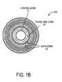
- FIG. 1Billustrates a top view of one embodiment of a magnetic disk of a disk drive system having a transition zone.
- FIG. 2Aillustrates a cross-sectional perspective view of one embodiment of a patterned data zone of the magnetic disk and a head.
- FIG. 2Billustrates a cross-sectional perspective view of an alternative embodiment of a patterned disk.
- FIGS. 3A , 3 B, and 3 Cillustrate alternative embodiments of data zone texture patterns.
- FIGS. 4A and 4Billustrate a cross-sectional view of one embodiment of the fly heights of a head over different zones of a magnetic recording disk.
- FIG. 5illustrates one embodiment of a process flow for positioning the head over the safe zone with reference to FIGS. 4A and 4B .
- FIGS. 6A , 6 B, 6 C, and 6 Dillustrate alternative embodiments of safe zone disk surface textures.
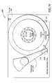
- FIG. 7illustrates one embodiment of a disk drive system.
- FIG. 8illustrates one embodiment of a computer system.
- FIG. 9illustrates one embodiment of a CSS zone laser induced bump.
- FIG. 10illustrates a cross-sectional view of fly heights of a head operating over a data zone, transition zone and CSS zone of a magnetic recording disk.
- FIG. 11illustrates one embodiment of a method of operating a head over the disk zones of FIG. 10 .
- FIG. 12illustrates a cross-sectional view of the fly heights of a head operating over a data zone, a transition zone and a ramp.
- FIG. 13illustrates one embodiment of a method of operating a head over the disk zones of FIG. 12 .
- FIG. 14illustrates a top view of one embodiment of a load/unload disk drive system.
- FIG. 15illustrates one embodiment of a slider having a padded air bearing surface.
- one layer or component disposed above or below another layermay be directly in contact with the other layer or component, or may have one or more intervening layers or components.
- one layer deposited or disposed between layersmay be directly in contact with the layers or may have one or more intervening layers.
- a safe zone on a magnetic recording diskis disclosed to enhance the reliability of a magnetic disk drive system.
- the safe zone on the magnetic recording diskcauses a head coupled to a slider over the safe zone to fly at a higher distance than the fly height of the head when the disk drive is in operation (e.g., during a write or read operation).
- One or more safe zonesmay be dispersed between data zone tracks of the disk, near the inner diameter of the disk and/or near/at the outer diameter of the disk.
- the safe zone on the magnetic recording diskcauses a head coupled to a slider to fly at a higher height while moving between a data zone and a landing zone on the disk.
- the higher fly height of the slider over such a safe zonereduces the possibility of the head inadvertently contacting a landing zone feature during transition to the landing zone.
- the safe zone in between the data zone and the landing zonemay also be referred to as a transition zone.
- the headis induced to fly higher by altering the disk's surface structure and/or texture in a safe/transition zone from the surface structure and/or texture in the data zone of the disk.
- the higher fly height of the head over a transition/safe zonereduces contact wear and enhances mechanical reliability of a disk drive system.
- FIG. 1Aillustrates a top view of one embodiment of a magnetic recording disk of a disk drive system.
- the magnetic recording disk (“disk”) 100includes a landing zone 10 , a safe zone 20 and one or more data zones 40 .
- Landing zone 10is where a slider (e.g., slider 1600 of FIG. 15 ) resides when the disk 100 is not rotating.
- the landing zone 10may be a CSS zone in a CSS type disk where the slider is in contact with the disk when the disk is not rotating.
- the inner diameter (ID) region on the disk 100may be used for the CSS zone.
- other regionssuch as an outer diameter region may be used for the landing zone 10 .
- the CSS zonehas a texture pattern (e.g., a laser induced bump texture) that reduces stiction when the slider lifts off from and lands on the landing zone 10 .
- Static friction, or stictionis a term used to describe the force exerted against the motion of the slider relative to the disk surface when the slider is at rest on the disk surface.
- FIG. 9illustrates one embodiment of a CSS zone laser induced bump.
- the laser induced bump 900may have a height 910 in approximately the range of 0.02 to 1 microinches.
- bump 900may have other heights. It should be understood that the invention is not limited to laser induced bumps. Rather, in alternative embodiments, other textures well known to those of ordinary skill in the art may also be used.
- the slidermay also include pads or small features such as texture, which act as contact surfaces with the disk surface in order to further reduce stiction, as discussed below in relation to FIG. 15 .
- the landing zone 10may be a non-contact area residing beneath a ramp (e.g., ramp 1205 of FIG. 12 ) in a load/unload type disk drive system (also referred to as a load/unload zone) where the slider is transitioned to and/or parked on the ramp, not the disk surface, when the disk is not rotating.
- a load/unload type disk drive systemalso referred to as a load/unload zone
- the disk 100need not have a landing zone 10 when used in a load/unload drive system, as will be explained.
- the non-contact area residing beneath the rampmay be an extension of transition zone 20 .
- the load/unload drivemay use a landing zone 10 having a transition zone 20 like surface extending out beyond the ramp.
- the safe zone 20may be a non-data zone having a surface structure and/or texture that induces the head to fly higher when the head is idling or approaching the landing zone 10 to park, as will be further described below.
- the surface texture of the safe zone 20may be different than the surface textures of the intended data zone 40 and the landing zone 10 , as is described below.
- the data zone 40may include magnetic material that may be manipulated to store data in a manner known to those of skill in the art.
- data zone 40includes a DTR pattern as discussed below in relation to FIGS. 2A and 2B .
- safe zone 20is also suitable for use with non-DTR patterned disks.
- the safe zone 20 and the landing zone 10have been described as a non-data zone, it should be understood that a non-data zone may contain servo signals to control the head positions.
- FIG. 2Aillustrates a cross-sectional perspective view of one embodiment of a patterned data zone of a magnetic disk and a head.
- the disk 100includes a substrate 120 , that may be textured, and multiple film layers disposed above the substrate 120 , some of which have been omitted for clarity of the following discussion.
- Substrate 120may be, for example, a glass substrate or a metal/metal alloy substrate.
- Glass substrates that may be usedinclude, for example, a silica containing glass such as borosilicate glass and aluminosilicate glass.
- Metal alloy substrates that may be usedinclude, for example, aluminum-magnesium (AlMg) substrates. In an alternative embodiment, other substrate materials including polymers and ceramics may be used.
- the reading and writing of data on the data zone 40 of the disk 100is accomplished by flying head 110 over the rotating disk 100 in a manner well known to those of ordinary skill in the art.
- the head 110is positioned above a writable data track of data zone 40 to change the polarization of the magnetic media of disk 100 and, thereby, store electronic data longitudinally or perpendicularly.
- head 110may have a magneto-resistive (MR) and, in particular, a giant magneto-resistive (GMR) read element and an inductive write element.
- MRmagneto-resistive
- GMRgiant magneto-resistive
- head 110may be another type of head, for examples, a Hall effect head or an inductive head having a common element for both read and write operations.
- Magnetic recording headsare known in the art; accordingly, a detailed description is not provided.
- disk 100may include a discrete track recording pattern formed, for example, in patterned layer 130 .
- One method for increasing recording densitiesis to pattern the surface of a disk to form discrete data tracks, referred to as discrete track recording (DTR).
- DTR diskstypically have a series of concentric raised areas (e.g., hills, lands, elevations, etc.) storing data and recessed areas (e.g., troughs, valleys, grooves, etc.) that may store servo information.
- the recessed areas 160separate the raised areas 170 to inhibit or prevent the unintended storage of data in the raised areas.
- the recessed areas 160have a depth 165 relative to the recording head 110 and/or raised areas 170 .
- the width 115 of the head 110is greater than the width 175 of the raised areas 170 such that portions of the head 110 extend over the recessed areas 160 during operation.
- the recessed areas 160are sufficiently separated by a distance 165 from the head 110 to inhibit storage of data by the head 110 in the magnetic layer 150 directly below the recessed areas 160 .
- the raised areas 170are sufficiently close to the head 110 to enable the writing of data in the magnetic layer 150 directly below the raised areas 170 .
- a width 175 of each raised zonemay be about 1250 angstroms ( ⁇ ) and a width of each recessed zone may be typically about 1 ⁇ 3 of the raised zone, or about 400 ⁇ .
- the raised and recessed zonesmay have a pitch between about 200-2000 ⁇ .
- a depth 165 of each recessed zonefor example, may be about 400 ⁇ . The dimensions discussed above are exemplary and may have other values.
- the discrete stamped patternmay be embossed, or otherwise formed, into the patterned layer 130 with the magnetic layer 150 disposed above the patterned layer 130 , either before or after embossing.
- the raised areas 170constitute the data tracks.
- Information, such as servo (head positioning) signalsmay be stored in the recessed areas 160 .
- servo signalsmay be interleaved with data in sectors and stored on the raised areas 170 .
- the raised areas 170 and recessed areas 160are typically formed as alternating concentric circles, although other configurations (e.g., spiral) are contemplated.
- the recessed areas 160isolate the raised areas 170 (e.g., the data tracks) from one another, resulting in data tracks that are defined both physically and magnetically.
- the formation of a DTR patternis known in the art; accordingly a detailed description is not provided.
- the discrete track patternmay include data islands as illustrated in FIG. 2B .
- Each of the data islands 190may hold a block of data (e.g., one bit or multiple bits) and are isolated from one another by the recessed areas, thereby forming a discrete bit recording pattern.
- Such a configurationmay reduce the amount of noise (e.g., noise between tracks and between blocks of data or bits) that is sensed by the read head 110 .
- the recessed and raised areasmay have alternative shapes that still isolate data blocks from recessed areas.
- the recessed areas 160could be partially filled with lubricant or other material to protect the wall of the recessed areas 160 from corrosion.
- the lubricantcan have higher vapor pressure (e.g., lower molecule weight) because the structure of the recessed areas 160 has a very small cavity, which can hold low pressure molecules whose mechanism is known as “capillary condensation” or “Thomson effect,” which is well known to those of ordinary skill in the art.
- a DTR patterninduces the slider (e.g., slider 1600 having head 110 ) to fly closer to the data zone's surface relative to a data zone without such a pattern.
- the fly height of head 110 over a DTR patterned data zonemay be, for example, approximately in the range of 0.05 to 1 microinches and the height 910 of a laser bump 900 in CSS zone 10 may be, for example, approximately in the range of 0.02 to 1 microinches.
- the fly height of a slider (e.g., slider 1600 —not shown in FIG. 2A ) over a data zone 40may be lower than the height of a laser induced bump or other structures in the landing zone 10 (as shown e.g., in FIG. 10 ).
- transition zone 20 between data zone 40 and landing zone 10reduces the probability of inadvertent contact of the slider with the landing zone 10 surface features during parking operations. Inadvertent contact between the slider and the texture features of landing zone 10 may cause damage or wear of the disk 100 surface and the slider, and the generation of debris.
- the use of a transition zone 20 on a disk 100may, thereby, greatly enhance the mechanical reliability of the slider-disk interface.
- the disk 100may be manufactured with a glass substrate or a metal/metal alloy substrate.
- Glass substratesthat may be used include, for example, a silica containing glass such as borosilicate glass and aluminosilicate glass.
- Metal alloy substratesthat may be used include, for example, AlMg substrates.
- other substrate materialssuch as polymers and ceramics may be used.
- one or more texturesmay be generated on the surface of the substrate 120 (or on a layer disposed on the substrate, e.g., a plated NiP layer) for one or more of the zones (data zone 40 , landing zone 10 and/or a safe zone 20 ).
- one of the layers below the data zone 40may be textured to produce a desired magnetic orientation in the magnetic film layer 150 .
- the texturing of the layer below the data zone 40may encourage preferred circumferential orientation of the magnetic media of magnetic recording layer 150 by affecting the orientation and size of the crystallites in the below residing under layers which, through the epitaxy of growing the magnetic layer 150 above the textured layer, in turn affects the orientation of the crystallites of the magnetic layer 150 , thereby inducing orientation of the magnetic media.
- Preferred circumferential orientation of the magnetic media on disk 100may aid in achieving optimal signal-to-noise ratio (SNR) and resolution to obtain the best possible performance from the magnetic media.
- SNRsignal-to-noise ratio
- Such a texturepropagates through above deposited layers to appear on the uppermost layer surface of disk 100 , as illustrated for examples in FIGS. 3A-3C .
- such a texturingneed not be limited to data zone 40 of disk 100 but may also appear on the landing zone 10 and/or transition zone 20 of disk 100 .
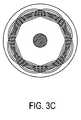
- FIGS. 3A , 3 B and 3 Cillustrate alternative embodiments of texture patterns.
- FIG. 3Aillustrates a magnetic disk having a rosette texture pattern.
- FIG. 3Billustrates a magnetic disk having a circumferential texture pattern.
- FIG. 3Cillustrates a magnetic disk having a crosshatch texture pattern.
- the circumferential texture pattern shown in FIG. 3Bhas microscopic circumferential (or substantially circumferential) grooves or scratches on the surface of the raised zones of the substrate 120 .
- Substrate 120may be mechanically textured using fixed or free abrasives.
- To generate a cross-hatch texturefor example, a substrate is clamped to the spindle platform that rotates during operation.
- a tape, treated with a diamond slurry,is mounted on the tape roller and positioned against the substrate.
- the machineis configured to oscillate the spindle, thereby moving the substrate back and forth, while the tape roller presses the tape against the surface of the substrate.
- the grooves in the substrateare created by the trajectories of individual diamond particles moved across the substrate surface.
- the resulting texture pattern made by the trajectoriesis a function of the frequency of both the substrate platform oscillation and the frequency of the substrate platform rotation.
- the particulate trajectorieswill not retrace themselves during successive disk rotations and, thus, generate groove crossings that interweave to form a cross-hatch texture in the substrate, as illustrated in FIG. 3C .
- other oscillation and rotation frequenciesmay be used.
- the oscillation and rotation frequenciesare matched (or e.g., have an integer ratio), or the platform/tape is not oscillated, the tape particulate trajectories result in a circumferential texture pattern in the substrate (or above deposited layer such as a NiP layer mentioned above), as illustrated in FIG. 3B .
- other texturing methodsmay be used such as emboss texturing and laser texturing. It should be understood that the invention is not limited to the texture patterns described herein, and alternative texture patterns well known to those of ordinary skill in the art may also be used.
- disk 100has a DTR pattern
- the aforementioned texturingrefers to the surface topology of the substantially horizontal recessed areas 160 and raised areas 170 rather than to the gross changes in height associated with the DTR pattern.
- the top surface of landing zone 10may be textured (e.g., with or without the under layer texturing discussed above) to reduce stiction between the slider and the surface of disk 100 .
- the CSS texture patternmay be applied to the disk by mechanically abrading the substrate surface using well known techniques. Alternatively, other methods may be used to provide the necessary texture in the CSS zone, for example, laser texturing. In laser texturing, a laser beam is focused to a small spot on the disk surface, forming uniformly shaped and sized textures in a controllable pattern.
- the landing zone 10may be, in one embodiment, textured more heavily than the data zone 40 portions of the disk used for data storage through the texturing on the substrate's surface that propagates through the subsequently deposited layers to appear on the surface of the top most layer (e.g., overcoat protection layer) on disk 100 .
- both the glide height (minimum distance at which a head slider may fly without contacting any portion of the disk surface) and the glide avalanche height (distance above mean disk surface level at which the head slider makes regular and continuous contact with the disk surface)are lower in the data zone 40 than in the CSS zone.
- the glide avalanche height of the portion of the disk by the amount of the laser bump heightincreases because the head 110 must be able to safely move between the two zones, without undue contact in the CSS zone that could lead to wear of the disk surface, the slider, and generation of debris.
- the immediate transition of the fly heightis typically not enough to overcome the height of the landing zone features such as, for example, laser induced bumps 900 .
- the use of a transition zone 20may also provide an additional margin against the inadvertent contacts between the slider and disk 100 during load/unload operations.
- FIGS. 6A-Dillustrate alternative safe zone disk surface textures that may be used to induce a head to fly higher than when the head is over a data zone.
- the surface of the disk 100 in the safe zone 20may be a planar smooth surface without a DTR pattern structure as illustrated in FIG. 6A .
- the planar surfacemay be a two-dimensional surface, which is substantially flat, with a substantially uniform depth and thickness relative to the DTR pattern.
- surface of the safe zone 20may have a texture generated by texturing of substrate 120 (or on a layer disposed on the substrate, e.g., a plated NiP layer) yet be planar with respect to the gross changes in height associated with a DTR pattern in data zone 40 .
- FIG. 6Billustrates a safe zone surface structure having radial grooves.
- the groovesare oriented radially at a spacing of approximately 10 micron pitch with lands that are approximately 10 microns wide.
- FIG. 6Cillustrates a safe zone surface structure having slanted grooves.
- FIG. 6Dillustrates a safe zone surface structure having cross-hatched grooves.
- the depth of the grooves in the safe zonemay be the same or less than the depth of the grooves relative to the planar surface in the data zone.
- the angles formed by the cross-hatched grooves in the safe zoneare different from the angles formed by the cross-hatch texture in the data zone. For example, the angles formed in the data zone are greater than the angles formed in the safe zone (e.g., 20 to 70 degrees made by the cross-hatch in the safe zone).
- the spacing of the groove and land geometryis optimized to alter the fly height of a head to be higher than over the data zone (e.g., circumferential DTR pattern surface structure).
- the surface patternsinduce the head to fly higher by lessening the amount of air leakage pressure building up under the head when the head is flying.
- yet other texture patternsmay also be used to increase the fly height of the head 110 , for example, a texture comprised of a matrix of circles.
- the texture pattern illustrated in FIGS. 6B , 6 C, and 6 Dmay also act as a cleaning surface for the air bearing surface (ABS) of head 110 in contact type recording drive systems.
- ABSair bearing surface
- One or more embossing toolsmay be used to create a discrete track pattern and/or the safe zone texture on the disk 100 .
- a stampermay be generated with a texture that is imparted to the raised areas 170 of the discrete track pattern in the data zone.
- a laser texture toolwell known to those of ordinary skill in the art, may be used to generate the various safe zone patterns on the disk 100 .
- the safe zone 20may be sized substantially to the width of head 100 (e.g., approximately 1 mm in width).
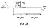
- FIGS. 4A and 4Billustrate a cross-sectional view of one embodiment of the fly heights of a head over magnetic recording disk 100 having a data zone and a safe zone.
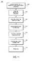
- FIG. 5illustrates a process flow for positioning a head 110 over a track of safe zone 20 with reference to FIGS. 4A and 4B .
- the electronic drive intelligence softwarereceives an instruction to perform a read and/or write operation to the data zone 40 of the magnetic disk 100 .
- the head 110is positioned over the data zone 40 at a fly height 11 to perform the read and/or write operation, as shown in FIG. 4A .
- the fly height 11 of head 110 over data zone 40may be approximately in the range of 0.05 to 1 microinches.
- the fly height 12 of head 110 over safe zone 20may be approximately in the range of 140-145% of the fly height 11 of head 110 over the data zone 40 .
- the fly height 12may be substantially the fly height 11 plus approximately 0.4 microinches. It should be noted that fly heights outside the exemplary ranges and percentages provided above may be used by changing the design of the air bearing and cavities.
- fly height 11 of head 110may be lower than 0.05 microinches, approaching approximately zero for contact recording operations. It should also be noted that the fly heights may not be uniform across a zone (in particular, data zone 40 ) due to difference in skew and linear speed from the ID to the OD of disk 100 .
- the read and/or write operationis performed.
- the head 110is positioned over the safe zone 20 at a fly height 12 , as shown in FIG. 4B . In this way, the fly height 12 of the head 110 over the safe zone 20 is greater than the fly height 11 of the read-write 110 when over the data zone 40 .
- the head 110becomes idle and the magnetic disk 100 continues to rotate, awaiting a subsequent instruction or transition to a parked position.
- the ability to increase the fly heightprovides clearance between the slider 1600 and disk 100 thus mitigating abrasive wear of the slider and disk. This is particularly desirable in disk drive systems utilizing contact or near contact recording head technology because such systems require either closer proximity or direct contact magnetic technology between the head and magnetic disk. It should be appreciated that since drive systems are not continuously reading and writing, a significant amount of time of slider/head-disk abrasion may be avoided by repositioning slider 1600 over one or more of the safe zone 20 where head 110 flies higher, thereby increasing the clearance between the slider 1600 and disk 100 , and avoiding contact with the disk while the disk system is idling or parking and not performing a read-write operation. In this way, the mechanical reliability of this slider-disk interface is greatly enhanced.
- the electronic drive intelligence softwaremay either instruct the head 110 to perform a subsequent read and/or write operation in the data zone 40 , or instruct the head 110 to return to the landing zone 10 .
- the slider 1600rests directly on the surface of the landing zone (in the embodiment where landing zone is a CSS zone) and the disk 100 ceases to rotate until a new operating instruction is received.
- electronic drive intelligence softwaremay be used by the magnetic disk drive system to control the movement of the head 110 over the landing zone 10 , the transition zone 20 and the data zone 40 .
- the electronic drive intelligence softwaredirects the head 110 over the transition zone 20 from the data zone 40 when the magnetic disk drive system receives an instruction to park the slider 1600 in the landing zone 10 , as will be described in further detail below.
- FIG. 10illustrates a cross-sectional view of the fly heights of a head operation over a data zone, transition zone and CSS zone of a magnetic recording disk.
- FIG. 11illustrates one embodiment of a method of operating a head over a magnetic recording disk with reference to FIG. 10 .
- the electronic drive intelligence softwarereceives an instruction to perform a read and/or write operation to the data zone 40 of the magnetic disk 100 .
- the data zone 40includes a DTR patterned surface.
- the electronic drive intelligence softwaredirects the positioning of the head 110 over the data zone 40 .
- the head 110is at a fly height 11 , as shown in FIG. 10 , when over the data zone 40 at least because of the air bearing pressure between the head 110 and the data zone 40 surface.
- the read and/or write operationis performed.
- the electronic drive intelligence softwarereceives an instruction to park the head 110 in the CSS landing zone 10 .
- the electronic drive intelligence softwaremay park the head 110 in the landing zone 10 , for example, when the disk drive system is powering down.
- the electronic drive intelligence softwaredirects the positioning of the head 110 over the transition zone 20 .
- the air pressure induced by the surface of the transition zone 20causes the fly height 11 of the head 110 to increase to fly height 12 as it travels over the transition zone 20 from the data zone 40 to the landing zone 10 as shown in FIG. 10 .
- the electronic drive intelligence softwaredirects the positioning of the head 110 over the landing zone 10 while parking. Also, the fly height 12 of the head 110 over the transition zone 20 ensures the head 110 sufficiently clears the surface 1010 (e.g., laser induced bumps) of the landing zone 10 as the head 110 continues to land on the landing zone 10 as shown in FIG. 10 .
- the electronic drive intelligence softwaredirects the head 110 to park in the CSS landing zone 10 .
- the slider 1600(having head 110 ) rests directly on the surface of the landing zone 10 and the disk 100 ceases to rotate until a new operating instruction is received.
- FIG. 12illustrates a cross-sectional view of a head operating over different zones of a disk and parked on a load/unload ramp.
- FIG. 13illustrates one embodiment of a method of operating a head over a disk with reference to FIG. 12 .
- the electronic drive intelligence softwarereceives an instruction to perform a read and/or write operation from the data zone 40 of the magnetic disk 101 .
- the data zone 40includes a DTR patterned surface.
- the electronic drive intelligence softwaredirects the positioning of the head 110 over the data zone 40 .
- the head 110is at a fly height 11 , as shown in FIG. 12 , when over the data zone 40 at least because of the air bearing pressure between the head 110 and the data zone 40 surface.
- the read and/or write operationis performed.
- the electronic drive intelligence softwarereceives an instruction to park the head 110 on the load ramp 1205 .
- the electronic drive intelligence softwaremay park a suspension arm 1460 , to which slider 1600 (and thereby head 110 ) is secured, on load/unload ramp 1205 , for example, when the disk drive system is powering down.
- the electronic drive intelligence softwaredirects the positioning of the head 110 over the safe zone 20 .
- the air pressure induced by the surface of the safe zone 20causes the fly height 11 of the head 110 to increase to fly height 15 as it travels over the transition zone 20 from the data zone 40 to load/unload ramp 11205 , as shown in FIG. 12 .
- the electronic drive intelligence softwarepositions the head 110 over the load ramp 1205 . Also, the fly height 15 of the head 110 over the safe zone 20 ensures the slider 1600 sufficiently clears the loading ramp 1205 while parking as shown in FIG. 12 . At block 1370 , the head 110 is parked on the loading ramp 1205 .
- FIGS. 5 , 11 , and 13may be embodied in machine-executable instructions, e.g. software.
- the instructionscan be used to cause a general-purpose or special-purpose processor that is programmed with the instructions to perform the operations described.
- the operationsmight be performed by specific hardware components that contain hardwired logic for performing the operations, or by any combination of programmed computer components and custom hardware components.
- the methodmay be provided as a computer program product that may include a machine-readable medium having stored thereon instructions that may be used to program a computer (or other electronic devices) to perform the method.
- machine-readable mediumshall be taken to include any medium that is capable of storing or encoding a sequence of instructions for execution by the machine and that cause the machine to perform any one of the methodologies of the present invention.
- the term “machine-readable medium”shall accordingly be taken to include, but not be limited to, solid-state memories, optical and magnetic disks, and a carrier wave that encodes a data signal.
- FIG. 7illustrates one embodiment of a CSS type disk drive system.
- Disk drive 700may include one or more of disk 100 to store data.
- Disk 100resides on a spindle assembly 760 that is mounted to drive housing 780 .
- Actuator 711is connected by a suspension arm 712 to slider 1600 .
- the actuator 711is connected to the drive housing 1080 and moves the suspension arm 712 and, thus head 110 in a radial direction to a desired location on the disk 100 .
- a spindle motor(not shown) rotates spindle assembly 760 and, thereby, disk 100 to position head 110 at a particular location along a desired disk track well known to those of ordinary skill in the art.
- head 110may be controlled by position control circuitry 770 (e.g., the electronic drive intelligence software may be stored in the position control circuitry 770 ).
- head 110may have a magneto-resistive (MR) and, in particular, a giant magneto-resistive (GMR) read element and an inductive write element.
- MRmagneto-resistive
- GMRgiant magneto-resistive
- head 110may be another type of head, for examples, a Hall effect head or an inductive head having a common element for both read and write operations.
- disk drive 700may be a CSS type disk drive.
- disk 100has a CSS zone 10 , a transition zone 20 and a data zone 40 .
- the electronic drive intelligence softwarecould also be programmed to instruct the suspension arm 712 to increase the fly height of head 110 over disk 100 .
- the slider 1600having head 110 coupled thereto, may include various components and features to further reduce stiction between slider 1600 and the surface of the CSS zone 10 of disk 100 , for examples, texturing, a positive crown (longitudinal curvature to the air bearing surface contour), and/or pads on the ABS of the slider (as illustrated in one embodiment in FIG. 15 ).
- FIG. 15illustrates one embodiment of a slider having a padded ABS.
- Slider 1600may include a slider body 1610 , protrusions, head 110 , and air bearing surface 1660 .
- the slider body 1600is attached to the suspension ( 712 or 1460 ) via a head gimbal assembly that load biases the slider body 1610 towards the disk 100 .
- the net effect of the air bearing surface 1660 and the suspensionis to cause the slider 1600 to fly at a desired height above disk 100 when the disk is rotating.
- the air bearing surface 1660may include one or more rails that generate a positive air pressure under slider 1600 .
- slider 1600may include a cavity 1607 or similar structure between the rails that creates a sub-ambient pressure to counterbalance the positive pressure generated by the suspension arm ( 712 or 1460 ), to some extent. Air bearing surfaces and rails are known in the art; accordingly, a more detailed discussion is not provided.
- slider 1600may include protrusions (e.g., protrusions 1647 , 1648 and 1649 , for example, disposed on leading edge step 1680 ) such as pads or a texture that may operate in conjunction with the patterned surface of the CSS zone to further reduce stiction.
- slider 1600may also include one or more protrusion on other sections of slider 1600 , for example, protrusion 1690 .
- a disk drive systemmay be configured such that the width of transition zone 20 is wider than a width of an air bearing surface of a slider (e.g., width 1602 ) but narrower than the width of the slider body (e.g., width 1601 ).
- FIG. 14illustrates one embodiment of a load/unload disk drive system.
- disk drive system 1400is a load/unload disk drive system having a ramp 1205 as a securing mechanism 1440 for the suspension arm 1460 .
- Ramp 1205is used to secure the head 110 coupled to a slider outside the outer diameter (OD) 1439 edge of disk 100 .
- a bottom portion of the ramp 1205may extend over OD 1439 of the disk 100 .
- head 110is positioned on ramp 1205 .
- the suspension arm 1460moves the head 110 down ramp 1205 so that head 110 flies after clearing the bottom of ramp 1205 .
- the suspension arm 1460moves head 110 up ramp 1205 to its parked position at the top.
- ramp 1205may be configured to secure head 110 inside the inner diameter (ID) 1437 edge of disk 100 .
- the ramp 1205may also be secured in disk drive system 1400 in various locations, for example, to the base of chassis 1480 , a cover (not shown), spindle hub 1490 , etc.
- the securing mechanism 1440may be discussed herein in reference to a ramp 1208 , the disk drive system 1400 is not limited to only a ramp type securing mechanism.
- securing mechanism 1440may be other types of mechanisms known in the art, for example, a pneumatic mechanism to dynamically load/unload slider 1600 .
- disk drive systems 700 and 1400may include double sided disks and multiple (single sided and/or double sided) disks in which each side of a disk may have a corresponding slider and suspension arm assembly.
- the disk drive systems 700 and 1400may be coupled to a computer system as illustrated in FIG. 8 .
- computer system 840may include a processor 850 , memory 855 , a disk drive system 700 / 1400 , and input/output capability 860 coupled to a system bus 865 .
- the memory 855is configured to store instructions, such as the electronic drive intelligence software, that when executed by the processor 850 , perform the methods described herein.
- Input/output 860allows for the transfer of data to and from the magnetic disk drive system 700 / 1400 .
- Input/output 860interface with a receiver, a transmitter, a visual display, and various types of machine-readable media, including any type of additional storage device that is accessible by the processor 850 .
- FIG. 8The description of FIG. 8 is intended to provide an overview of computer hardware and other operating components suitable for implementing the embodiments of the invention, but is not intended to limit the applicable environments.
- the computer system 840is one example of many possible computer systems that have different architectures.
- a typical computer systemwill usually include at least a processor, memory, and a bus coupling the memory to the processor.
- processorsprocessors
- memorymemory
- buscoupling the memory to the processor.
- embodiments of the inventioncan be practiced with other computer system configurations, including multiprocessor systems, minicomputers, mainframe computers, and the like.
Landscapes
- Engineering & Computer Science (AREA)
- Chemical & Material Sciences (AREA)
- Nanotechnology (AREA)
- Physics & Mathematics (AREA)
- Mathematical Physics (AREA)
- Theoretical Computer Science (AREA)
- Crystallography & Structural Chemistry (AREA)
- Magnetic Record Carriers (AREA)
- Adjustment Of The Magnetic Head Position Track Following On Tapes (AREA)
- Manufacturing Of Magnetic Record Carriers (AREA)
Abstract
Description
Claims (6)
Priority Applications (2)
| Application Number | Priority Date | Filing Date | Title |
|---|---|---|---|
| US11/605,762US7733605B2 (en) | 2003-03-05 | 2006-11-28 | Magnetic recording disk having a transition zone |
| US12/776,702US8064156B1 (en) | 2003-03-05 | 2010-05-10 | Magnetic recording disk having a transition zone |
Applications Claiming Priority (3)
| Application Number | Priority Date | Filing Date | Title |
|---|---|---|---|
| US10/382,635US7016154B2 (en) | 2003-03-05 | 2003-03-05 | Magnetic recording disk having a safe zone |
| US10/701,059US7199977B2 (en) | 2003-03-05 | 2003-11-03 | Magnetic recording disk having a transition zone |
| US11/605,762US7733605B2 (en) | 2003-03-05 | 2006-11-28 | Magnetic recording disk having a transition zone |
Related Parent Applications (1)
| Application Number | Title | Priority Date | Filing Date |
|---|---|---|---|
| US10/701,059DivisionUS7199977B2 (en) | 2003-03-05 | 2003-11-03 | Magnetic recording disk having a transition zone |
Related Child Applications (1)
| Application Number | Title | Priority Date | Filing Date |
|---|---|---|---|
| US12/776,702ContinuationUS8064156B1 (en) | 2003-03-05 | 2010-05-10 | Magnetic recording disk having a transition zone |
Publications (2)
| Publication Number | Publication Date |
|---|---|
| US20070070541A1 US20070070541A1 (en) | 2007-03-29 |
| US7733605B2true US7733605B2 (en) | 2010-06-08 |
Family
ID=32871630
Family Applications (3)
| Application Number | Title | Priority Date | Filing Date |
|---|---|---|---|
| US11/605,906AbandonedUS20070070549A1 (en) | 2003-03-05 | 2006-11-28 | Magnetic recording disk having a transition zone |
| US11/605,762Expired - Fee RelatedUS7733605B2 (en) | 2003-03-05 | 2006-11-28 | Magnetic recording disk having a transition zone |
| US12/776,702Expired - Fee RelatedUS8064156B1 (en) | 2003-03-05 | 2010-05-10 | Magnetic recording disk having a transition zone |
Family Applications Before (1)
| Application Number | Title | Priority Date | Filing Date |
|---|---|---|---|
| US11/605,906AbandonedUS20070070549A1 (en) | 2003-03-05 | 2006-11-28 | Magnetic recording disk having a transition zone |
Family Applications After (1)
| Application Number | Title | Priority Date | Filing Date |
|---|---|---|---|
| US12/776,702Expired - Fee RelatedUS8064156B1 (en) | 2003-03-05 | 2010-05-10 | Magnetic recording disk having a transition zone |
Country Status (3)
| Country | Link |
|---|---|
| US (3) | US20070070549A1 (en) |
| JP (1) | JP2004362734A (en) |
| DE (1) | DE102004010336A1 (en) |
Cited By (69)
| Publication number | Priority date | Publication date | Assignee | Title |
|---|---|---|---|---|
| US20070070549A1 (en)* | 2003-03-05 | 2007-03-29 | Shoji Suzuki | Magnetic recording disk having a transition zone |
| US8828566B2 (en) | 2010-05-21 | 2014-09-09 | Wd Media (Singapore) Pte. Ltd. | Perpendicular magnetic recording disc |
| US8859118B2 (en) | 2010-01-08 | 2014-10-14 | Wd Media (Singapore) Pte. Ltd. | Perpendicular magnetic recording medium |
| US8867322B1 (en) | 2013-05-07 | 2014-10-21 | WD Media, LLC | Systems and methods for providing thermal barrier bilayers for heat assisted magnetic recording media |
| US8877359B2 (en) | 2008-12-05 | 2014-11-04 | Wd Media (Singapore) Pte. Ltd. | Magnetic disk and method for manufacturing same |
| US8908315B2 (en) | 2010-03-29 | 2014-12-09 | Wd Media (Singapore) Pte. Ltd. | Evaluation method of magnetic disk, manufacturing method of magnetic disk, and magnetic disk |
| US8941950B2 (en) | 2012-05-23 | 2015-01-27 | WD Media, LLC | Underlayers for heat assisted magnetic recording (HAMR) media |
| US8947987B1 (en) | 2013-05-03 | 2015-02-03 | WD Media, LLC | Systems and methods for providing capping layers for heat assisted magnetic recording media |
| US8951651B2 (en) | 2010-05-28 | 2015-02-10 | Wd Media (Singapore) Pte. Ltd. | Perpendicular magnetic recording disk |
| US8980076B1 (en) | 2009-05-26 | 2015-03-17 | WD Media, LLC | Electro-deposited passivation coatings for patterned media |
| US8995078B1 (en) | 2014-09-25 | 2015-03-31 | WD Media, LLC | Method of testing a head for contamination |
| US8993134B2 (en) | 2012-06-29 | 2015-03-31 | Western Digital Technologies, Inc. | Electrically conductive underlayer to grow FePt granular media with (001) texture on glass substrates |
| US9001630B1 (en) | 2011-03-08 | 2015-04-07 | Western Digital Technologies, Inc. | Energy assisted magnetic recording medium capable of suppressing high DC readback noise |
| US9005782B2 (en) | 2008-03-30 | 2015-04-14 | WD Media, LLC | Magnetic disk and method of manufacturing the same |
| US9025264B1 (en) | 2011-03-10 | 2015-05-05 | WD Media, LLC | Methods for measuring media performance associated with adjacent track interference |
| US9028985B2 (en) | 2011-03-31 | 2015-05-12 | WD Media, LLC | Recording media with multiple exchange coupled magnetic layers |
| US9029308B1 (en) | 2012-03-28 | 2015-05-12 | WD Media, LLC | Low foam media cleaning detergent |
| US9034492B1 (en) | 2013-01-11 | 2015-05-19 | WD Media, LLC | Systems and methods for controlling damping of magnetic media for heat assisted magnetic recording |
| US9042053B1 (en) | 2014-06-24 | 2015-05-26 | WD Media, LLC | Thermally stabilized perpendicular magnetic recording medium |
| US9047903B2 (en) | 2008-03-26 | 2015-06-02 | Wd Media (Singapore) Pte. Ltd. | Perpendicular magnetic recording medium and process for manufacture thereof |
| US9047880B1 (en) | 2011-12-20 | 2015-06-02 | WD Media, LLC | Heat assisted magnetic recording method for media having moment keeper layer |
| US9064521B1 (en) | 2011-03-25 | 2015-06-23 | WD Media, LLC | Manufacturing of hard masks for patterning magnetic media |
| US9082447B1 (en) | 2014-09-22 | 2015-07-14 | WD Media, LLC | Determining storage media substrate material type |
| US9093100B2 (en) | 2008-03-17 | 2015-07-28 | Wd Media (Singapore) Pte. Ltd. | Magnetic recording medium including tailored exchange coupling layer and manufacturing method of the same |
| US9093122B1 (en) | 2013-04-05 | 2015-07-28 | WD Media, LLC | Systems and methods for improving accuracy of test measurements involving aggressor tracks written to disks of hard disk drives |
| US9129633B1 (en) | 2014-08-22 | 2015-09-08 | Seagate Technology Llc | Adaptive defect avoidance device |
| US9142241B2 (en) | 2009-03-30 | 2015-09-22 | Wd Media (Singapore) Pte. Ltd. | Perpendicular magnetic recording medium and method of manufacturing the same |
| US9153268B1 (en) | 2013-02-19 | 2015-10-06 | WD Media, LLC | Lubricants comprising fluorinated graphene nanoribbons for magnetic recording media structure |
| US9159350B1 (en) | 2014-07-02 | 2015-10-13 | WD Media, LLC | High damping cap layer for magnetic recording media |
| US9177586B2 (en) | 2008-09-30 | 2015-11-03 | WD Media (Singapore), LLC | Magnetic disk and manufacturing method thereof |
| US9177585B1 (en) | 2013-10-23 | 2015-11-03 | WD Media, LLC | Magnetic media capable of improving magnetic properties and thermal management for heat-assisted magnetic recording |
| US9183867B1 (en) | 2013-02-21 | 2015-11-10 | WD Media, LLC | Systems and methods for forming implanted capping layers in magnetic media for magnetic recording |
| US9190094B2 (en) | 2013-04-04 | 2015-11-17 | Western Digital (Fremont) | Perpendicular recording media with grain isolation initiation layer and exchange breaking layer for signal-to-noise ratio enhancement |
| US9196283B1 (en) | 2013-03-13 | 2015-11-24 | Western Digital (Fremont), Llc | Method for providing a magnetic recording transducer using a chemical buffer |
| US9218850B1 (en) | 2014-12-23 | 2015-12-22 | WD Media, LLC | Exchange break layer for heat-assisted magnetic recording media |
| US9227324B1 (en) | 2014-09-25 | 2016-01-05 | WD Media, LLC | Mandrel for substrate transport system with notch |
| US9240204B2 (en) | 2010-05-21 | 2016-01-19 | Wd Media (Singapore) Pte. Ltd. | Perpendicular magnetic recording disc |
| US9257134B1 (en) | 2014-12-24 | 2016-02-09 | Western Digital Technologies, Inc. | Allowing fast data zone switches on data storage devices |
| US9269480B1 (en) | 2012-03-30 | 2016-02-23 | WD Media, LLC | Systems and methods for forming magnetic recording media with improved grain columnar growth for energy assisted magnetic recording |
| US9275669B1 (en) | 2015-03-31 | 2016-03-01 | WD Media, LLC | TbFeCo in PMR media for SNR improvement |
| US9280998B1 (en) | 2015-03-30 | 2016-03-08 | WD Media, LLC | Acidic post-sputter wash for magnetic recording media |
| US9296082B1 (en) | 2013-06-11 | 2016-03-29 | WD Media, LLC | Disk buffing apparatus with abrasive tape loading pad having a vibration absorbing layer |
| US9330685B1 (en) | 2009-11-06 | 2016-05-03 | WD Media, LLC | Press system for nano-imprinting of recording media with a two step pressing method |
| US9339978B1 (en) | 2009-11-06 | 2016-05-17 | WD Media, LLC | Press system with interleaved embossing foil holders for nano-imprinting of recording media |
| US9349404B2 (en) | 2010-05-28 | 2016-05-24 | Wd Media (Singapore) Pte. Ltd | Perpendicular magnetic recording disc |
| US9382496B1 (en) | 2013-12-19 | 2016-07-05 | Western Digital Technologies, Inc. | Lubricants with high thermal stability for heat-assisted magnetic recording |
| US9389135B2 (en) | 2013-09-26 | 2016-07-12 | WD Media, LLC | Systems and methods for calibrating a load cell of a disk burnishing machine |
| US9401300B1 (en) | 2014-12-18 | 2016-07-26 | WD Media, LLC | Media substrate gripper including a plurality of snap-fit fingers |
| US9406330B1 (en) | 2013-06-19 | 2016-08-02 | WD Media, LLC | Method for HDD disk defect source detection |
| US9406329B1 (en) | 2015-11-30 | 2016-08-02 | WD Media, LLC | HAMR media structure with intermediate layer underlying a magnetic recording layer having multiple sublayers |
| US9431045B1 (en) | 2014-04-25 | 2016-08-30 | WD Media, LLC | Magnetic seed layer used with an unbalanced soft underlayer |
| US9449633B1 (en) | 2014-11-06 | 2016-09-20 | WD Media, LLC | Smooth structures for heat-assisted magnetic recording media |
| US9447368B1 (en) | 2014-02-18 | 2016-09-20 | WD Media, LLC | Detergent composition with low foam and high nickel solubility |
| US9472227B2 (en) | 2010-06-22 | 2016-10-18 | Wd Media (Singapore) Pte. Ltd. | Perpendicular magnetic recording media and methods for producing the same |
| US9542968B1 (en) | 2010-08-20 | 2017-01-10 | WD Media, LLC | Single layer small grain size FePT:C film for heat assisted magnetic recording media |
| US9558778B2 (en) | 2009-03-28 | 2017-01-31 | Wd Media (Singapore) Pte. Ltd. | Lubricant compound for magnetic disk and magnetic disk |
| US9581510B1 (en) | 2013-12-16 | 2017-02-28 | Western Digital Technologies, Inc. | Sputter chamber pressure gauge with vibration absorber |
| US9607646B2 (en) | 2013-07-30 | 2017-03-28 | WD Media, LLC | Hard disk double lubrication layer |
| US9685184B1 (en) | 2014-09-25 | 2017-06-20 | WD Media, LLC | NiFeX-based seed layer for magnetic recording media |
| US9818442B2 (en) | 2014-12-01 | 2017-11-14 | WD Media, LLC | Magnetic media having improved magnetic grain size distribution and intergranular segregation |
| US9824711B1 (en) | 2014-02-14 | 2017-11-21 | WD Media, LLC | Soft underlayer for heat assisted magnetic recording media |
| US9822441B2 (en) | 2015-03-31 | 2017-11-21 | WD Media, LLC | Iridium underlayer for heat assisted magnetic recording media |
| US9990940B1 (en) | 2014-12-30 | 2018-06-05 | WD Media, LLC | Seed structure for perpendicular magnetic recording media |
| US10054363B2 (en) | 2014-08-15 | 2018-08-21 | WD Media, LLC | Method and apparatus for cryogenic dynamic cooling |
| US10083715B2 (en) | 2010-05-28 | 2018-09-25 | WD Media (Singapore) Pte.Ltd. | Method of manufacturing a perpendicular magnetic disc |
| US10115428B1 (en) | 2013-02-15 | 2018-10-30 | Wd Media, Inc. | HAMR media structure having an anisotropic thermal barrier layer |
| US10121506B1 (en) | 2015-12-29 | 2018-11-06 | WD Media, LLC | Magnetic-recording medium including a carbon overcoat implanted with nitrogen and hydrogen |
| US10236026B1 (en) | 2015-11-06 | 2019-03-19 | WD Media, LLC | Thermal barrier layers and seed layers for control of thermal and structural properties of HAMR media |
| US11074934B1 (en) | 2015-09-25 | 2021-07-27 | Western Digital Technologies, Inc. | Heat assisted magnetic recording (HAMR) media with Curie temperature reduction layer |
Families Citing this family (5)
| Publication number | Priority date | Publication date | Assignee | Title |
|---|---|---|---|---|
| US7986492B2 (en)* | 2007-09-06 | 2011-07-26 | Samsung Electronics Co., Ltd. | Process for filling a patterned media of a hard disk with UV-cured lubricant |
| US20100081010A1 (en)* | 2008-09-26 | 2010-04-01 | Fujifilm Corporation | Imprint mold structure, magnetic recording medium and method for producing the magnetic recording medium |
| WO2010109538A1 (en)* | 2009-03-27 | 2010-09-30 | 東芝ストレージデバイス株式会社 | Magnetic disc, magnetic disc manufacturing method and magnetic disc device |
| US8576671B1 (en) | 2012-12-07 | 2013-11-05 | Sae Magnetics (H.K) Ltd. | ABS design with multiple heaters |
| JP2025099707A (en)* | 2023-12-22 | 2025-07-03 | 株式会社東芝 | Magnetic disk device |
Citations (41)
| Publication number | Priority date | Publication date | Assignee | Title |
|---|---|---|---|---|
| JPH0411324A (en) | 1990-04-27 | 1992-01-16 | Toshiba Corp | magnetic disk device |
| JPH05210929A (en) | 1992-01-30 | 1993-08-20 | Sony Corp | Disk driving device |
| US5377058A (en) | 1992-12-31 | 1994-12-27 | International Business Machines Corporation | Fly height servo control of read/write head suspension |
| US5504646A (en)* | 1989-10-13 | 1996-04-02 | Hitachi, Ltd. | Magnetic disk including protective layer having surface with protusions and magnetic disk apparatus including the magnetic disk |
| US5550696A (en)* | 1995-01-27 | 1996-08-27 | International Business Machines Corporation | Magnetic recording disk having textured test band for controlling texture in the slider landing zone |
| EP0731451A2 (en) | 1995-03-07 | 1996-09-11 | Hitachi, Ltd. | Magnetic disk & method for manufacturing the same and magnetic disk unit obtained by the same |
| US5574604A (en) | 1993-12-21 | 1996-11-12 | International Business Machines Coporation | Inner diameter disk drive head/slider load/unload device |
| US5586040A (en)* | 1995-01-27 | 1996-12-17 | International Business Machines Corporation | Process and apparatus for controlled laser texturing of magnetic recording disk |
| US5644451A (en) | 1995-05-26 | 1997-07-01 | Samsung Information Systems America, Inc. | Mechanism for loading and unloading of read/write heads at an inner diameter of a disk |
| US5673156A (en) | 1993-06-21 | 1997-09-30 | Komag, Inc. | Hard disk drive system having virtual contact recording |
| US5736020A (en)* | 1995-04-24 | 1998-04-07 | Hmt Technology Corporation | Target assembly for use in forming an overcoat in a magnetic recording medium |
| US5798164A (en) | 1995-06-23 | 1998-08-25 | Stormedia, Inc. | Zone textured magnetic recording media |
| US5870265A (en) | 1995-07-27 | 1999-02-09 | Seagate Technology, Inc. | Magnetic recording disc having an idle fly zone and tapering transition zones on each side thereof |
| US5870250A (en) | 1996-03-01 | 1999-02-09 | International Business Machines Corporation | Method and apparatus for improving file capacity using different flying height profiles |
| JPH1145420A (en)* | 1997-07-28 | 1999-02-16 | Toshiba Corp | Magnetic disk and magnetic disk device provided with the disk |
| US5875083A (en) | 1994-06-30 | 1999-02-23 | Sony Corporation | Magnetic disc having planiarized CSS zone |
| US5958542A (en)* | 1995-06-06 | 1999-09-28 | Hitachi, Ltd. | Thin film magnetic disc and method of manufacturing the disc |
| US6020045A (en) | 1996-06-05 | 2000-02-01 | Seagate Technology, Inc. | Textured magnetic recording medium having a transition zone |
| US6057984A (en)* | 1995-10-25 | 2000-05-02 | Mitsubishi Chemical Corporation | Method for data writing/read-out using a contact start and stop system |
| US6075683A (en) | 1993-04-26 | 2000-06-13 | International Business Machines Corporation | Disk drive with passive multiple fly height slider and cooperative disk pattern |
| JP2000293840A (en)* | 1999-04-09 | 2000-10-20 | Fuji Electric Co Ltd | Magnetic disk |
| US6139936A (en) | 1995-09-06 | 2000-10-31 | Akashic Memories Corporation | Discrete track media produced by underlayer laser ablation |
| US6164118A (en) | 1998-09-30 | 2000-12-26 | Komag Incorporated | Calibration disk having discrete bands of calibration bumps |
| JP2001034929A (en) | 1999-07-26 | 2001-02-09 | Hitachi Ltd | Magnetic disk and magnetic disk drive |
| US6292333B1 (en)* | 1999-02-11 | 2001-09-18 | Western Digital Technologies, Inc. | Disk drive having an I.D. ramp loading system employing multiple-function spacer structure |
| US20010043441A1 (en)* | 2000-05-22 | 2001-11-22 | Fujitsu Limited | Load/unload mechanism stably holding head slider in recording disk drive |
| US6330124B1 (en) | 1996-12-20 | 2001-12-11 | Nec Corporation | Magnetic disk device using a contact start stop system |
| US6351345B1 (en) | 1999-01-12 | 2002-02-26 | Fujitsu Limited | Air bearing slider and method of producing the same |
| US20020024774A1 (en) | 2000-08-29 | 2002-02-28 | International Business Machines Corporation | Method and apparatus for dynamically controlling the flying behaviour and height of a read/write head in a storage device |
| US20020030937A1 (en) | 1999-07-28 | 2002-03-14 | Hain-Ling Liu | Super-textured air bearing surface slider design for data transducers in rotating media random access computer mass storage devices |
| US6381090B1 (en) | 1998-05-21 | 2002-04-30 | Komag, Incorporated | Hard disk drive head-media system having reduced stiction and low fly height |
| JP2002513493A (en) | 1996-06-05 | 2002-05-08 | シーゲイト テクノロジー エルエルシー | Textured magnetic recording medium with transition zone |
| WO2002084650A1 (en) | 2001-04-18 | 2002-10-24 | International Business Machines Corporation | Air bearing slider |
| US6473259B1 (en) | 1999-09-24 | 2002-10-29 | Seagate Technology Llc | Disk head height control |
| US6529347B2 (en) | 2000-10-13 | 2003-03-04 | Seagate Technology Llc | Disc drive slider having textured pads |
| US20030044647A1 (en)* | 2001-09-05 | 2003-03-06 | Iraj Kavosh | Laser textured magnetic disk |
| US6563673B2 (en) | 2000-09-12 | 2003-05-13 | Seagate Technology Llc | Method and apparatus for minimizing slider fly heights over patterned media |
| US6597539B1 (en) | 1999-03-31 | 2003-07-22 | Maxtor Corporation | Suspension assembly for supporting a read/write head over a rotating storage disk with dynamically adjustable fly height |
| US20050013047A1 (en) | 2003-07-17 | 2005-01-20 | Tdk Corporation | Magnetic recording medium |
| US6927941B1 (en)* | 1997-03-28 | 2005-08-09 | Hitachi Global Storage Technologies Netherlands Bv | Disk drive disk with landing zone having textured and untextured regions |
| US7016154B2 (en) | 2003-03-05 | 2006-03-21 | Komag, Inc. | Magnetic recording disk having a safe zone |
Family Cites Families (11)
| Publication number | Priority date | Publication date | Assignee | Title |
|---|---|---|---|---|
| US5539213A (en)* | 1995-01-27 | 1996-07-23 | International Business Machines Corporation | Process and apparatus for laser analysis of surface having a repetitive texture pattern |
| JPH0981932A (en) | 1995-07-07 | 1997-03-28 | Kao Corp | Magnetic recording medium and method of manufacturing the same |
| US5729399A (en)* | 1995-12-13 | 1998-03-17 | International Business Machines Corporation | Contact start/stop disk drive with minimized head-disk wear in textured landing zone |
| US5798884A (en)* | 1995-12-13 | 1998-08-25 | International Business Machines Corporation | Multiple zone data storage system and method |
| US6239935B1 (en)* | 1996-02-05 | 2001-05-29 | Seagate Technolgy Llc | Method and apparatus for starting a hard disk drive having separate landing and data zones |
| US5734522A (en)* | 1996-07-10 | 1998-03-31 | Seagate Technology, Inc. | Disc drive system with slider for reading and writing adjacent portions of a zone textured disc |
| US6205002B1 (en)* | 1997-06-13 | 2001-03-20 | International Business Machines Corporation | Disk drive with textured slider contact region |
| US5959814A (en)* | 1997-09-16 | 1999-09-28 | Quantum Corporation | Magnetic disk having separate park and take-off zones |
| JPH11273061A (en) | 1998-03-20 | 1999-10-08 | Toshiba Corp | Disk medium and disk device mounted with the medium |
| JP2000251249A (en) | 1999-02-24 | 2000-09-14 | Fuji Electric Co Ltd | Media substrate for magnetic recording |
| DE102004010336A1 (en)* | 2003-03-05 | 2004-09-16 | Komag, Inc., San Jose | Magnetic recording disc with transition zone |
- 2004
- 2004-03-03DEDE102004010336Apatent/DE102004010336A1/ennot_activeWithdrawn
- 2004-03-05JPJP2004063202Apatent/JP2004362734A/enactivePending
- 2006
- 2006-11-28USUS11/605,906patent/US20070070549A1/ennot_activeAbandoned
- 2006-11-28USUS11/605,762patent/US7733605B2/ennot_activeExpired - Fee Related
- 2010
- 2010-05-10USUS12/776,702patent/US8064156B1/ennot_activeExpired - Fee Related
Patent Citations (44)
| Publication number | Priority date | Publication date | Assignee | Title |
|---|---|---|---|---|
| US5504646A (en)* | 1989-10-13 | 1996-04-02 | Hitachi, Ltd. | Magnetic disk including protective layer having surface with protusions and magnetic disk apparatus including the magnetic disk |
| JPH0411324A (en) | 1990-04-27 | 1992-01-16 | Toshiba Corp | magnetic disk device |
| JPH05210929A (en) | 1992-01-30 | 1993-08-20 | Sony Corp | Disk driving device |
| US5377058A (en) | 1992-12-31 | 1994-12-27 | International Business Machines Corporation | Fly height servo control of read/write head suspension |
| US6075683A (en) | 1993-04-26 | 2000-06-13 | International Business Machines Corporation | Disk drive with passive multiple fly height slider and cooperative disk pattern |
| US5673156A (en) | 1993-06-21 | 1997-09-30 | Komag, Inc. | Hard disk drive system having virtual contact recording |
| US5574604A (en) | 1993-12-21 | 1996-11-12 | International Business Machines Coporation | Inner diameter disk drive head/slider load/unload device |
| US5875083A (en) | 1994-06-30 | 1999-02-23 | Sony Corporation | Magnetic disc having planiarized CSS zone |
| US5586040A (en)* | 1995-01-27 | 1996-12-17 | International Business Machines Corporation | Process and apparatus for controlled laser texturing of magnetic recording disk |
| US5550696A (en)* | 1995-01-27 | 1996-08-27 | International Business Machines Corporation | Magnetic recording disk having textured test band for controlling texture in the slider landing zone |
| EP0731451A2 (en) | 1995-03-07 | 1996-09-11 | Hitachi, Ltd. | Magnetic disk & method for manufacturing the same and magnetic disk unit obtained by the same |
| US5736020A (en)* | 1995-04-24 | 1998-04-07 | Hmt Technology Corporation | Target assembly for use in forming an overcoat in a magnetic recording medium |
| US5644451A (en) | 1995-05-26 | 1997-07-01 | Samsung Information Systems America, Inc. | Mechanism for loading and unloading of read/write heads at an inner diameter of a disk |
| US5958542A (en)* | 1995-06-06 | 1999-09-28 | Hitachi, Ltd. | Thin film magnetic disc and method of manufacturing the disc |
| US5798164A (en) | 1995-06-23 | 1998-08-25 | Stormedia, Inc. | Zone textured magnetic recording media |
| US5870265A (en) | 1995-07-27 | 1999-02-09 | Seagate Technology, Inc. | Magnetic recording disc having an idle fly zone and tapering transition zones on each side thereof |
| US6139936A (en) | 1995-09-06 | 2000-10-31 | Akashic Memories Corporation | Discrete track media produced by underlayer laser ablation |
| US6057984A (en)* | 1995-10-25 | 2000-05-02 | Mitsubishi Chemical Corporation | Method for data writing/read-out using a contact start and stop system |
| US5870250A (en) | 1996-03-01 | 1999-02-09 | International Business Machines Corporation | Method and apparatus for improving file capacity using different flying height profiles |
| US6020045A (en) | 1996-06-05 | 2000-02-01 | Seagate Technology, Inc. | Textured magnetic recording medium having a transition zone |
| JP2002513493A (en) | 1996-06-05 | 2002-05-08 | シーゲイト テクノロジー エルエルシー | Textured magnetic recording medium with transition zone |
| US6330124B1 (en) | 1996-12-20 | 2001-12-11 | Nec Corporation | Magnetic disk device using a contact start stop system |
| US6927941B1 (en)* | 1997-03-28 | 2005-08-09 | Hitachi Global Storage Technologies Netherlands Bv | Disk drive disk with landing zone having textured and untextured regions |
| JPH1145420A (en)* | 1997-07-28 | 1999-02-16 | Toshiba Corp | Magnetic disk and magnetic disk device provided with the disk |
| US6381090B1 (en) | 1998-05-21 | 2002-04-30 | Komag, Incorporated | Hard disk drive head-media system having reduced stiction and low fly height |
| US6164118A (en) | 1998-09-30 | 2000-12-26 | Komag Incorporated | Calibration disk having discrete bands of calibration bumps |
| US6351345B1 (en) | 1999-01-12 | 2002-02-26 | Fujitsu Limited | Air bearing slider and method of producing the same |
| US6292333B1 (en)* | 1999-02-11 | 2001-09-18 | Western Digital Technologies, Inc. | Disk drive having an I.D. ramp loading system employing multiple-function spacer structure |
| US6597539B1 (en) | 1999-03-31 | 2003-07-22 | Maxtor Corporation | Suspension assembly for supporting a read/write head over a rotating storage disk with dynamically adjustable fly height |
| JP2000293840A (en)* | 1999-04-09 | 2000-10-20 | Fuji Electric Co Ltd | Magnetic disk |
| JP2001034929A (en) | 1999-07-26 | 2001-02-09 | Hitachi Ltd | Magnetic disk and magnetic disk drive |
| US20020030937A1 (en) | 1999-07-28 | 2002-03-14 | Hain-Ling Liu | Super-textured air bearing surface slider design for data transducers in rotating media random access computer mass storage devices |
| US6473259B1 (en) | 1999-09-24 | 2002-10-29 | Seagate Technology Llc | Disk head height control |
| US20010043441A1 (en)* | 2000-05-22 | 2001-11-22 | Fujitsu Limited | Load/unload mechanism stably holding head slider in recording disk drive |
| WO2002019330A1 (en) | 2000-08-29 | 2002-03-07 | International Business Machines Corporation | Method and apparatus for dynamically controlling the flying behaviour and height of a read/write head in a storage device |
| US20020024774A1 (en) | 2000-08-29 | 2002-02-28 | International Business Machines Corporation | Method and apparatus for dynamically controlling the flying behaviour and height of a read/write head in a storage device |
| US6563673B2 (en) | 2000-09-12 | 2003-05-13 | Seagate Technology Llc | Method and apparatus for minimizing slider fly heights over patterned media |
| US6529347B2 (en) | 2000-10-13 | 2003-03-04 | Seagate Technology Llc | Disc drive slider having textured pads |
| WO2002084650A1 (en) | 2001-04-18 | 2002-10-24 | International Business Machines Corporation | Air bearing slider |
| US20020181153A1 (en)* | 2001-04-18 | 2002-12-05 | Soo-Choon Kang | Slider air bearing surface having improved fly height profile characteristics |
| US20030044647A1 (en)* | 2001-09-05 | 2003-03-06 | Iraj Kavosh | Laser textured magnetic disk |
| US7016154B2 (en) | 2003-03-05 | 2006-03-21 | Komag, Inc. | Magnetic recording disk having a safe zone |
| US7199977B2 (en) | 2003-03-05 | 2007-04-03 | Komag, Inc. | Magnetic recording disk having a transition zone |
| US20050013047A1 (en) | 2003-07-17 | 2005-01-20 | Tdk Corporation | Magnetic recording medium |
Non-Patent Citations (13)
| Title |
|---|
| Interview Summary dated Apr. 22, 2009 from U.S. Appl. No. 11/605,906, 4 pages. |
| Office Action dated Aug. 19, 2009 from U.S. Appl. No. 11/605,906, 14 pages. |
| Office Action dated Aug. 21, 2008 from U.S. Appl. No. 11/605,906, 7 pages. |
| Office Action dated Dec. 17, 2009 from U.S. Appl. No. 11/605,906, 14 pages. |
| Office Action dated Jan. 16, 2009 from U.S. Appl. No. 11/605,906, 12 pages. |
| Office Action dated Jan. 22, 2008, from U.S. Appl. No. 11/605,906, 10 pages. |
| Office Action dated Oct. 23, 2009 from U.S. Appl. No. 11/605,906, 3 pages. |
| Patent Abstracts of Japan, Publication No. 09-081932, Mar. 28, 1997. |
| Patent Abstracts of Japan, Publication No. 09-167305, Jun. 24, 1997. |
| Patent Abstracts of Japan, Publication No. 11-273061, Aug. 10, 1999. |
| Patent Abstracts of Japan, Publication No. 2000-251249, Sep. 14, 2000. |
| Patent Abstracts of Japan, Publication No. 2000-293840, Oct. 20, 2000. |
| Shoji Tanaka et al. "Characterization of Magnetizing Process for Pre-Embossed Servo Pattern of Plastic Hard Disks", IEEE Transactions on Magnetics, vol. 30, No. 6, Nov. 1994, p. 4209-4211. |
Cited By (72)
| Publication number | Priority date | Publication date | Assignee | Title |
|---|---|---|---|---|
| US8064156B1 (en) | 2003-03-05 | 2011-11-22 | Wd Media, Inc. | Magnetic recording disk having a transition zone |
| US20070070549A1 (en)* | 2003-03-05 | 2007-03-29 | Shoji Suzuki | Magnetic recording disk having a transition zone |
| US9093100B2 (en) | 2008-03-17 | 2015-07-28 | Wd Media (Singapore) Pte. Ltd. | Magnetic recording medium including tailored exchange coupling layer and manufacturing method of the same |
| US9047903B2 (en) | 2008-03-26 | 2015-06-02 | Wd Media (Singapore) Pte. Ltd. | Perpendicular magnetic recording medium and process for manufacture thereof |
| US9005782B2 (en) | 2008-03-30 | 2015-04-14 | WD Media, LLC | Magnetic disk and method of manufacturing the same |
| US9177586B2 (en) | 2008-09-30 | 2015-11-03 | WD Media (Singapore), LLC | Magnetic disk and manufacturing method thereof |
| US9984715B2 (en) | 2008-09-30 | 2018-05-29 | WD Media, LLC | Magnetic disk and manufacturing method thereof |
| US8877359B2 (en) | 2008-12-05 | 2014-11-04 | Wd Media (Singapore) Pte. Ltd. | Magnetic disk and method for manufacturing same |
| US9558778B2 (en) | 2009-03-28 | 2017-01-31 | Wd Media (Singapore) Pte. Ltd. | Lubricant compound for magnetic disk and magnetic disk |
| US9142241B2 (en) | 2009-03-30 | 2015-09-22 | Wd Media (Singapore) Pte. Ltd. | Perpendicular magnetic recording medium and method of manufacturing the same |
| US8980076B1 (en) | 2009-05-26 | 2015-03-17 | WD Media, LLC | Electro-deposited passivation coatings for patterned media |
| US9330685B1 (en) | 2009-11-06 | 2016-05-03 | WD Media, LLC | Press system for nano-imprinting of recording media with a two step pressing method |
| US9339978B1 (en) | 2009-11-06 | 2016-05-17 | WD Media, LLC | Press system with interleaved embossing foil holders for nano-imprinting of recording media |
| US8859118B2 (en) | 2010-01-08 | 2014-10-14 | Wd Media (Singapore) Pte. Ltd. | Perpendicular magnetic recording medium |
| US8908315B2 (en) | 2010-03-29 | 2014-12-09 | Wd Media (Singapore) Pte. Ltd. | Evaluation method of magnetic disk, manufacturing method of magnetic disk, and magnetic disk |
| US8828566B2 (en) | 2010-05-21 | 2014-09-09 | Wd Media (Singapore) Pte. Ltd. | Perpendicular magnetic recording disc |
| US9240204B2 (en) | 2010-05-21 | 2016-01-19 | Wd Media (Singapore) Pte. Ltd. | Perpendicular magnetic recording disc |
| US10083715B2 (en) | 2010-05-28 | 2018-09-25 | WD Media (Singapore) Pte.Ltd. | Method of manufacturing a perpendicular magnetic disc |
| US8951651B2 (en) | 2010-05-28 | 2015-02-10 | Wd Media (Singapore) Pte. Ltd. | Perpendicular magnetic recording disk |
| US9349404B2 (en) | 2010-05-28 | 2016-05-24 | Wd Media (Singapore) Pte. Ltd | Perpendicular magnetic recording disc |
| US9472227B2 (en) | 2010-06-22 | 2016-10-18 | Wd Media (Singapore) Pte. Ltd. | Perpendicular magnetic recording media and methods for producing the same |
| US9542968B1 (en) | 2010-08-20 | 2017-01-10 | WD Media, LLC | Single layer small grain size FePT:C film for heat assisted magnetic recording media |
| US9001630B1 (en) | 2011-03-08 | 2015-04-07 | Western Digital Technologies, Inc. | Energy assisted magnetic recording medium capable of suppressing high DC readback noise |
| US9025264B1 (en) | 2011-03-10 | 2015-05-05 | WD Media, LLC | Methods for measuring media performance associated with adjacent track interference |
| US9064521B1 (en) | 2011-03-25 | 2015-06-23 | WD Media, LLC | Manufacturing of hard masks for patterning magnetic media |
| US9028985B2 (en) | 2011-03-31 | 2015-05-12 | WD Media, LLC | Recording media with multiple exchange coupled magnetic layers |
| US9047880B1 (en) | 2011-12-20 | 2015-06-02 | WD Media, LLC | Heat assisted magnetic recording method for media having moment keeper layer |
| US9029308B1 (en) | 2012-03-28 | 2015-05-12 | WD Media, LLC | Low foam media cleaning detergent |
| US9269480B1 (en) | 2012-03-30 | 2016-02-23 | WD Media, LLC | Systems and methods for forming magnetic recording media with improved grain columnar growth for energy assisted magnetic recording |
| US8941950B2 (en) | 2012-05-23 | 2015-01-27 | WD Media, LLC | Underlayers for heat assisted magnetic recording (HAMR) media |
| US8993134B2 (en) | 2012-06-29 | 2015-03-31 | Western Digital Technologies, Inc. | Electrically conductive underlayer to grow FePt granular media with (001) texture on glass substrates |
| US9034492B1 (en) | 2013-01-11 | 2015-05-19 | WD Media, LLC | Systems and methods for controlling damping of magnetic media for heat assisted magnetic recording |
| US10115428B1 (en) | 2013-02-15 | 2018-10-30 | Wd Media, Inc. | HAMR media structure having an anisotropic thermal barrier layer |
| US9153268B1 (en) | 2013-02-19 | 2015-10-06 | WD Media, LLC | Lubricants comprising fluorinated graphene nanoribbons for magnetic recording media structure |
| US9183867B1 (en) | 2013-02-21 | 2015-11-10 | WD Media, LLC | Systems and methods for forming implanted capping layers in magnetic media for magnetic recording |
| US9196283B1 (en) | 2013-03-13 | 2015-11-24 | Western Digital (Fremont), Llc | Method for providing a magnetic recording transducer using a chemical buffer |
| US9190094B2 (en) | 2013-04-04 | 2015-11-17 | Western Digital (Fremont) | Perpendicular recording media with grain isolation initiation layer and exchange breaking layer for signal-to-noise ratio enhancement |
| US9093122B1 (en) | 2013-04-05 | 2015-07-28 | WD Media, LLC | Systems and methods for improving accuracy of test measurements involving aggressor tracks written to disks of hard disk drives |
| US8947987B1 (en) | 2013-05-03 | 2015-02-03 | WD Media, LLC | Systems and methods for providing capping layers for heat assisted magnetic recording media |
| US8867322B1 (en) | 2013-05-07 | 2014-10-21 | WD Media, LLC | Systems and methods for providing thermal barrier bilayers for heat assisted magnetic recording media |
| US9296082B1 (en) | 2013-06-11 | 2016-03-29 | WD Media, LLC | Disk buffing apparatus with abrasive tape loading pad having a vibration absorbing layer |
| US9406330B1 (en) | 2013-06-19 | 2016-08-02 | WD Media, LLC | Method for HDD disk defect source detection |
| US9607646B2 (en) | 2013-07-30 | 2017-03-28 | WD Media, LLC | Hard disk double lubrication layer |
| US9389135B2 (en) | 2013-09-26 | 2016-07-12 | WD Media, LLC | Systems and methods for calibrating a load cell of a disk burnishing machine |
| US9177585B1 (en) | 2013-10-23 | 2015-11-03 | WD Media, LLC | Magnetic media capable of improving magnetic properties and thermal management for heat-assisted magnetic recording |
| US9581510B1 (en) | 2013-12-16 | 2017-02-28 | Western Digital Technologies, Inc. | Sputter chamber pressure gauge with vibration absorber |
| US9382496B1 (en) | 2013-12-19 | 2016-07-05 | Western Digital Technologies, Inc. | Lubricants with high thermal stability for heat-assisted magnetic recording |
| US9824711B1 (en) | 2014-02-14 | 2017-11-21 | WD Media, LLC | Soft underlayer for heat assisted magnetic recording media |
| US9447368B1 (en) | 2014-02-18 | 2016-09-20 | WD Media, LLC | Detergent composition with low foam and high nickel solubility |
| US9431045B1 (en) | 2014-04-25 | 2016-08-30 | WD Media, LLC | Magnetic seed layer used with an unbalanced soft underlayer |
| US9042053B1 (en) | 2014-06-24 | 2015-05-26 | WD Media, LLC | Thermally stabilized perpendicular magnetic recording medium |
| US9159350B1 (en) | 2014-07-02 | 2015-10-13 | WD Media, LLC | High damping cap layer for magnetic recording media |
| US10054363B2 (en) | 2014-08-15 | 2018-08-21 | WD Media, LLC | Method and apparatus for cryogenic dynamic cooling |
| US9129633B1 (en) | 2014-08-22 | 2015-09-08 | Seagate Technology Llc | Adaptive defect avoidance device |
| US9082447B1 (en) | 2014-09-22 | 2015-07-14 | WD Media, LLC | Determining storage media substrate material type |
| US9685184B1 (en) | 2014-09-25 | 2017-06-20 | WD Media, LLC | NiFeX-based seed layer for magnetic recording media |
| US8995078B1 (en) | 2014-09-25 | 2015-03-31 | WD Media, LLC | Method of testing a head for contamination |
| US9227324B1 (en) | 2014-09-25 | 2016-01-05 | WD Media, LLC | Mandrel for substrate transport system with notch |
| US9449633B1 (en) | 2014-11-06 | 2016-09-20 | WD Media, LLC | Smooth structures for heat-assisted magnetic recording media |
| US9818442B2 (en) | 2014-12-01 | 2017-11-14 | WD Media, LLC | Magnetic media having improved magnetic grain size distribution and intergranular segregation |
| US10783915B2 (en) | 2014-12-01 | 2020-09-22 | Western Digital Technologies, Inc. | Magnetic media having improved magnetic grain size distribution and intergranular segregation |
| US9401300B1 (en) | 2014-12-18 | 2016-07-26 | WD Media, LLC | Media substrate gripper including a plurality of snap-fit fingers |
| US9218850B1 (en) | 2014-12-23 | 2015-12-22 | WD Media, LLC | Exchange break layer for heat-assisted magnetic recording media |
| US9257134B1 (en) | 2014-12-24 | 2016-02-09 | Western Digital Technologies, Inc. | Allowing fast data zone switches on data storage devices |
| US9990940B1 (en) | 2014-12-30 | 2018-06-05 | WD Media, LLC | Seed structure for perpendicular magnetic recording media |
| US9280998B1 (en) | 2015-03-30 | 2016-03-08 | WD Media, LLC | Acidic post-sputter wash for magnetic recording media |
| US9275669B1 (en) | 2015-03-31 | 2016-03-01 | WD Media, LLC | TbFeCo in PMR media for SNR improvement |
| US9822441B2 (en) | 2015-03-31 | 2017-11-21 | WD Media, LLC | Iridium underlayer for heat assisted magnetic recording media |
| US11074934B1 (en) | 2015-09-25 | 2021-07-27 | Western Digital Technologies, Inc. | Heat assisted magnetic recording (HAMR) media with Curie temperature reduction layer |
| US10236026B1 (en) | 2015-11-06 | 2019-03-19 | WD Media, LLC | Thermal barrier layers and seed layers for control of thermal and structural properties of HAMR media |
| US9406329B1 (en) | 2015-11-30 | 2016-08-02 | WD Media, LLC | HAMR media structure with intermediate layer underlying a magnetic recording layer having multiple sublayers |
| US10121506B1 (en) | 2015-12-29 | 2018-11-06 | WD Media, LLC | Magnetic-recording medium including a carbon overcoat implanted with nitrogen and hydrogen |
Also Published As
| Publication number | Publication date |
|---|---|
| JP2004362734A (en) | 2004-12-24 |
| US20070070541A1 (en) | 2007-03-29 |
| DE102004010336A1 (en) | 2004-09-16 |
| US20070070549A1 (en) | 2007-03-29 |
| US8064156B1 (en) | 2011-11-22 |
Similar Documents
| Publication | Publication Date | Title |
|---|---|---|
| US7733605B2 (en) | Magnetic recording disk having a transition zone | |
| US7199977B2 (en) | Magnetic recording disk having a transition zone | |
| US6967798B2 (en) | Magnetic recording disk having DTR patterned CSS zone | |
| US6212042B1 (en) | Slider having air bearing surface which includes pads for disk storage system | |
| US7301726B1 (en) | Banded LZT CSS zone | |
| US6452752B1 (en) | Slider for disc storage system | |
| US6552871B2 (en) | Hard disk drive head-media system having reduced stiction and low fly height | |
| US6683754B2 (en) | Hard disk drive head-media system having reduced stiction and low fly height | |
| WO2002011142A2 (en) | Disk head slider having cavities for increasing contact stiffness and controlling suction center movement | |
| US6680821B2 (en) | Slider air bearing surface having improved fly height profile characteristics | |
| US7029590B2 (en) | Self-limiting wear contact pad slider and method for making the same | |
| US6231801B1 (en) | Method to reduce wear for proximity recording in a magnetic disc storage system | |
| US6549360B1 (en) | Magnetic recording medium with laser-formed servo-marks | |
| US20030184916A1 (en) | Air bearing slider having textured contact region to provide a self-adjusting fly height interface | |
| US6611400B1 (en) | Texture structure for optimizing head disc interface | |
| US7092213B1 (en) | Multiple level surface configuration for a sub-ambient pressure air bearing slider | |
| US20020015262A1 (en) | Head slider and disk drive unit employing the same | |
| US6519114B1 (en) | Magnetic storage medium having a textured zone | |
| US6535352B2 (en) | Head media interface for stiction control | |
| JPH07153069A (en) | Magnetic disc | |
| JP4181064B2 (en) | Manufacturing method of recording medium | |
| JPH09282628A (en) | Recording head, magnetic head, magnetic disk device, and storage device | |
| JP2010140584A (en) | Magnetic recording medium and storage device |
Legal Events
| Date | Code | Title | Description |
|---|---|---|---|
| AS | Assignment | Owner name:WD MEDIA, INC., CALIFORNIA Free format text:MERGER;ASSIGNOR:KOMAG, INC.;REEL/FRAME:020257/0216 Effective date:20070905 Owner name:WD MEDIA, INC.,CALIFORNIA Free format text:MERGER;ASSIGNOR:KOMAG, INC.;REEL/FRAME:020257/0216 Effective date:20070905 | |
| AS | Assignment | Owner name:KOMAG, INC., CALIFORNIA Free format text:ASSIGNMENT OF ASSIGNORS INTEREST;ASSIGNORS:SUZUKI, SHOJI;NISHIHIRA, HENRY S.;REEL/FRAME:020437/0599 Effective date:20031030 Owner name:KOMAG, INC.,CALIFORNIA Free format text:ASSIGNMENT OF ASSIGNORS INTEREST;ASSIGNORS:SUZUKI, SHOJI;NISHIHIRA, HENRY S.;REEL/FRAME:020437/0599 Effective date:20031030 | |
| REMI | Maintenance fee reminder mailed | ||
| FPAY | Fee payment | Year of fee payment:4 | |
| SULP | Surcharge for late payment | ||
| AS | Assignment | Owner name:JPMORGAN CHASE BANK, N.A., AS COLLATERAL AGENT, ILLINOIS Free format text:SECURITY AGREEMENT;ASSIGNOR:WD MEDIA, LLC;REEL/FRAME:038709/0879 Effective date:20160512 Owner name:U.S. BANK NATIONAL ASSOCIATION, AS COLLATERAL AGENT, CALIFORNIA Free format text:SECURITY AGREEMENT;ASSIGNOR:WD MEDIA, LLC;REEL/FRAME:038709/0931 Effective date:20160512 Owner name:JPMORGAN CHASE BANK, N.A., AS COLLATERAL AGENT, ILLINOIS Free format text:SECURITY AGREEMENT;ASSIGNOR:WD MEDIA, LLC;REEL/FRAME:038710/0383 Effective date:20160512 Owner name:U.S. BANK NATIONAL ASSOCIATION, AS COLLATERAL AGEN Free format text:SECURITY AGREEMENT;ASSIGNOR:WD MEDIA, LLC;REEL/FRAME:038709/0931 Effective date:20160512 Owner name:JPMORGAN CHASE BANK, N.A., AS COLLATERAL AGENT, IL Free format text:SECURITY AGREEMENT;ASSIGNOR:WD MEDIA, LLC;REEL/FRAME:038709/0879 Effective date:20160512 Owner name:JPMORGAN CHASE BANK, N.A., AS COLLATERAL AGENT, IL Free format text:SECURITY AGREEMENT;ASSIGNOR:WD MEDIA, LLC;REEL/FRAME:038710/0383 Effective date:20160512 | |
| FEPP | Fee payment procedure | Free format text:MAINTENANCE FEE REMINDER MAILED (ORIGINAL EVENT CODE: REM.) | |
| AS | Assignment | Owner name:WD MEDIA, LLC, CALIFORNIA Free format text:RELEASE BY SECURED PARTY;ASSIGNOR:U.S. BANK NATIONAL ASSOCIATION, AS COLLATERAL AGENT;REEL/FRAME:045501/0672 Effective date:20180227 | |
| LAPS | Lapse for failure to pay maintenance fees | Free format text:PATENT EXPIRED FOR FAILURE TO PAY MAINTENANCE FEES (ORIGINAL EVENT CODE: EXP.) | |
| STCH | Information on status: patent discontinuation | Free format text:PATENT EXPIRED DUE TO NONPAYMENT OF MAINTENANCE FEES UNDER 37 CFR 1.362 | |
| FP | Lapsed due to failure to pay maintenance fee | Effective date:20180608 | |
| AS | Assignment | Owner name:WESTERN DIGITAL TECHNOLOGIES, INC., CALIFORNIA Free format text:RELEASE OF SECURITY INTEREST AT REEL 038710 FRAME 0383;ASSIGNOR:JPMORGAN CHASE BANK, N.A.;REEL/FRAME:058965/0410 Effective date:20220203 Owner name:WD MEDIA, LLC, CALIFORNIA Free format text:RELEASE OF SECURITY INTEREST AT REEL 038710 FRAME 0383;ASSIGNOR:JPMORGAN CHASE BANK, N.A.;REEL/FRAME:058965/0410 Effective date:20220203 |