US7733239B2 - Distance determining system and method - Google Patents
Distance determining system and methodDownload PDFInfo
- Publication number
- US7733239B2 US7733239B2US11/382,247US38224706AUS7733239B2US 7733239 B2US7733239 B2US 7733239B2US 38224706 AUS38224706 AUS 38224706AUS 7733239 B2US7733239 B2US 7733239B2
- Authority
- US
- United States
- Prior art keywords
- transceiver
- electromagnetic wave
- distance
- transmitter
- timer
- Prior art date
- Legal status (The legal status is an assumption and is not a legal conclusion. Google has not performed a legal analysis and makes no representation as to the accuracy of the status listed.)
- Active, expires
Links
Images


Classifications
- G—PHYSICS
- G01—MEASURING; TESTING
- G01S—RADIO DIRECTION-FINDING; RADIO NAVIGATION; DETERMINING DISTANCE OR VELOCITY BY USE OF RADIO WAVES; LOCATING OR PRESENCE-DETECTING BY USE OF THE REFLECTION OR RERADIATION OF RADIO WAVES; ANALOGOUS ARRANGEMENTS USING OTHER WAVES
- G01S13/00—Systems using the reflection or reradiation of radio waves, e.g. radar systems; Analogous systems using reflection or reradiation of waves whose nature or wavelength is irrelevant or unspecified
- G01S13/74—Systems using reradiation of radio waves, e.g. secondary radar systems; Analogous systems
- G01S13/75—Systems using reradiation of radio waves, e.g. secondary radar systems; Analogous systems using transponders powered from received waves, e.g. using passive transponders, or using passive reflectors
- G01S13/751—Systems using reradiation of radio waves, e.g. secondary radar systems; Analogous systems using transponders powered from received waves, e.g. using passive transponders, or using passive reflectors wherein the responder or reflector radiates a coded signal
- G01S13/758—Systems using reradiation of radio waves, e.g. secondary radar systems; Analogous systems using transponders powered from received waves, e.g. using passive transponders, or using passive reflectors wherein the responder or reflector radiates a coded signal using a signal generator powered by the interrogation signal
- B—PERFORMING OPERATIONS; TRANSPORTING
- B60—VEHICLES IN GENERAL
- B60G—VEHICLE SUSPENSION ARRANGEMENTS
- B60G11/00—Resilient suspensions characterised by arrangement, location or kind of springs
- B60G11/26—Resilient suspensions characterised by arrangement, location or kind of springs having fluid springs only, e.g. hydropneumatic springs
- B60G11/27—Resilient suspensions characterised by arrangement, location or kind of springs having fluid springs only, e.g. hydropneumatic springs wherein the fluid is a gas
- B—PERFORMING OPERATIONS; TRANSPORTING
- B60—VEHICLES IN GENERAL
- B60G—VEHICLE SUSPENSION ARRANGEMENTS
- B60G17/00—Resilient suspensions having means for adjusting the spring or vibration-damper characteristics, for regulating the distance between a supporting surface and a sprung part of vehicle or for locking suspension during use to meet varying vehicular or surface conditions, e.g. due to speed or load
- B60G17/015—Resilient suspensions having means for adjusting the spring or vibration-damper characteristics, for regulating the distance between a supporting surface and a sprung part of vehicle or for locking suspension during use to meet varying vehicular or surface conditions, e.g. due to speed or load the regulating means comprising electric or electronic elements
- B60G17/018—Resilient suspensions having means for adjusting the spring or vibration-damper characteristics, for regulating the distance between a supporting surface and a sprung part of vehicle or for locking suspension during use to meet varying vehicular or surface conditions, e.g. due to speed or load the regulating means comprising electric or electronic elements characterised by the use of a specific signal treatment or control method
- B—PERFORMING OPERATIONS; TRANSPORTING
- B60—VEHICLES IN GENERAL
- B60G—VEHICLE SUSPENSION ARRANGEMENTS
- B60G17/00—Resilient suspensions having means for adjusting the spring or vibration-damper characteristics, for regulating the distance between a supporting surface and a sprung part of vehicle or for locking suspension during use to meet varying vehicular or surface conditions, e.g. due to speed or load
- B60G17/015—Resilient suspensions having means for adjusting the spring or vibration-damper characteristics, for regulating the distance between a supporting surface and a sprung part of vehicle or for locking suspension during use to meet varying vehicular or surface conditions, e.g. due to speed or load the regulating means comprising electric or electronic elements
- B60G17/019—Resilient suspensions having means for adjusting the spring or vibration-damper characteristics, for regulating the distance between a supporting surface and a sprung part of vehicle or for locking suspension during use to meet varying vehicular or surface conditions, e.g. due to speed or load the regulating means comprising electric or electronic elements characterised by the type of sensor or the arrangement thereof
- B—PERFORMING OPERATIONS; TRANSPORTING
- B60—VEHICLES IN GENERAL
- B60G—VEHICLE SUSPENSION ARRANGEMENTS
- B60G17/00—Resilient suspensions having means for adjusting the spring or vibration-damper characteristics, for regulating the distance between a supporting surface and a sprung part of vehicle or for locking suspension during use to meet varying vehicular or surface conditions, e.g. due to speed or load
- B60G17/02—Spring characteristics, e.g. mechanical springs and mechanical adjusting means
- B60G17/04—Spring characteristics, e.g. mechanical springs and mechanical adjusting means fluid spring characteristics
- B60G17/052—Pneumatic spring characteristics
- B—PERFORMING OPERATIONS; TRANSPORTING
- B60—VEHICLES IN GENERAL
- B60G—VEHICLE SUSPENSION ARRANGEMENTS
- B60G2202/00—Indexing codes relating to the type of spring, damper or actuator
- B60G2202/10—Type of spring
- B60G2202/15—Fluid spring
- B60G2202/152—Pneumatic spring
- B—PERFORMING OPERATIONS; TRANSPORTING
- B60—VEHICLES IN GENERAL
- B60G—VEHICLE SUSPENSION ARRANGEMENTS
- B60G2206/00—Indexing codes related to the manufacturing of suspensions: constructional features, the materials used, procedures or tools
- B60G2206/01—Constructional features of suspension elements, e.g. arms, dampers, springs
- B60G2206/40—Constructional features of dampers and/or springs
- B60G2206/42—Springs
- B—PERFORMING OPERATIONS; TRANSPORTING
- B60—VEHICLES IN GENERAL
- B60G—VEHICLE SUSPENSION ARRANGEMENTS
- B60G2400/00—Indexing codes relating to detected, measured or calculated conditions or factors
- B60G2400/25—Stroke; Height; Displacement
- B60G2400/252—Stroke; Height; Displacement vertical
- B—PERFORMING OPERATIONS; TRANSPORTING
- B60—VEHICLES IN GENERAL
- B60G—VEHICLE SUSPENSION ARRANGEMENTS
- B60G2401/00—Indexing codes relating to the type of sensors based on the principle of their operation
- B60G2401/17—Magnetic/Electromagnetic
- B60G2401/176—Radio or audio sensitive means, e.g. Ultrasonic
Definitions
- the present novel conceptbroadly relates to the art of distance measurement and, more particularly, to a system and method for determining a distance between associated structural members using electromagnetic carrier wave modulation and timing.
- the subject system and methodare amenable to broad use in a wide variety of applications and environments.
- One example of a suitable applicationis the use of the subject system and method on and with an associated fluid suspension member, such as an air spring of a vehicle, for example.
- the subject system and methodwill be discussed in detail hereinafter with specific reference to use on such an associated fluid suspension member.
- the subject system and methodare capable of broader application and are not intended to be limited to this specific example of a suitable application.
- a variety of well known and commonly used devices and arrangementshave been and are currently used to monitor the relative position of one structural member to another.
- mechanical linkage sensorsthat include one or more linkage members are often used to connect between adjacent structural members, such as a suspension component of a vehicle and a corresponding frame or body of the same.
- the linkage memberstypically act through a variable resistor or other suitable component that changes in response to the movement of the linkage.
- An electronic control unit (ECU) or other suitable devicedetermines the relative position of one structural member to the other based, for example, upon a corresponding change in voltage across the variable resistor or a corresponding change in current through the resistor.
- ECUelectronice control unit
- mechanical linkage sensorsAnother problem with mechanical linkage sensors is that the electronic components thereof are typically exposed to harsh environmental conditions (e.g., temperature extremes, water, dirt, salt) normally experienced by a vehicle traveling along a roadway. As a result of such exposure, the electronic components of the sensors can become corroded and fail to function properly. Due to one or both of these or other problems, one or more of the mechanical linkage sensors may be non-operational at any given time. Thus, regular inspection and replacement of such sensors is typically required.
- harsh environmental conditionse.g., temperature extremes, water, dirt, salt
- non-contact sensorsthat utilize sound or pressure waves traveling through a fluid medium, typically at an ultrasonic frequency, have been used in determining the relative position of one structural member to another.
- a fluid suspension membersuch as an air spring assembly
- the ultrasonic sensoris supported on one end member of the air spring and sends ultrasonic waves through the spring chamber of the air spring toward the opposing end member. The waves are reflected back by a suitable feature of the opposing end member and the distance therebetween is determined in a conventional manner.
- ultrasonic sensoris at least partially sheltered from impacts and exposure.
- numerous disadvantagesalso exist with the use of ultrasonic sensors.
- One such disadvantageis that such sensors are relatively expensive which tends to undesirably increase production costs.
- the replacement cost of a sensor that does get damaged by an impact or from exposureis likewise increased.
- ultrasonic sensorsrequire a target that is suitable to reflect the ultrasonic waves back to the sensor for determining the distance therebetween. If a such a target is not provided, the ultrasonic waves will not be reflected back properly and, thus, a correct determination of distance will not be possible. Thus, a target area must be provided for the proper operation of ultrasonic sensors. This can be particularly problematic, however, where the design constraints of a product limit the possibilities for including a target area. This is also a problem for existing products are being outfitted with ultrasonic sensors, where the existing products do not have a suitable target area.
- a distance determining system in accordance with one exemplary embodiment of the present novel concept for use with an associated fluid spring assemblyincludes a first transceiver operative to output a first electromagnetic wave and receive a second electromagnetic wave.
- a second transceiveris spaced a distance from the first transceiver and is operative to receive the first electromagnetic wave and output the second electromagnetic wave.
- the first transceiverincludes a timer operative to determine an elapsed time having a relation to the output of the first electromagnetic wave from the first transceiver and the receipt of the second electromagnetic wave at the first transceiver.
- the timeris operative to generate an elapsed time signal having a relation to the determined elapsed time.
- a fluid spring assembly in accordance with one exemplary embodiment of the present novel conceptincludes a first end member, a second end member spaced from the first end member, and a flexible wall secured between the first and second end members and at least partially forming a spring chamber therebetween.
- a first transceiveris supported along the first end member and includes a timer. The first transceiver is adapted to output a first electromagnetic wave.
- a second transceiveris supported along the second end member and is adapted to receive the first electromagnetic wave and output the second electromagnetic wave. The first transceiver is adapted to receive the second electromagnetic wave.
- the timeris adapted to determine an elapsed time between the first transceiver outputting the first electromagnetic wave and the first transceiver receiving the second electromagnetic wave.
- One exemplary method in accordance with the present novel concept of determining a distance having a relation to spaced end members of an associated fluid spring assemblyincludes providing a first transceiver supported along an associated first end member and including a timer.
- the first transceiveris operative to output a first electromagnetic wave and receive a second electromagnetic wave.
- the methodalso includes providing a second transceiver supported along an associated second end member. The second transceiver being operative to receive the first electromagnetic wave and output the second electromagnetic wave.
- the methodfurther includes starting the timer, outputting the first electromagnetic wave from the first transceiver, and receiving the first electromagnetic wave at the second transceiver.
- the methodalso includes outputting the second electromagnetic wave from the second transceiver and receiving the second electromagnetic wave at the first transceiver.
- the methodfurther includes stopping the timer and determining a elapsed time therefrom.
- the methodalso includes determining the distance based at least in part upon the elapsed time.
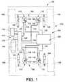
- FIG. 1is a representation of one exemplary embodiment of a distance determining system in accordance with the present novel concept shown in operative association on a vehicle.
- FIG. 2is a side view, in partial cross section, of one exemplary embodiment of an air spring assembly including a distance indicating system in accordance with the present novel concept.
- FIG. 3is a schematic representation of one exemplary embodiment of a distance determining system in accordance with the present novel concept.
- FIG. 4is a schematic representation of another exemplary embodiment of a distance determining system in accordance with the present novel concept.
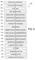
- FIG. 5is a diagrammatic representation of one exemplary method of determining a distance in accordance with the present novel concept.
- FIG. 1illustrates a vehicle 100 having a sprung mass, such as a vehicle body 102 , for example, and an unsprung mass, such as axles 104 and wheels 106 , for example.
- a plurality of damping members, such as shock absorbers 108are secured between the sprung and unsprung masses of the vehicle in a suitable manner.
- a plurality of fluid spring members, such as air spring assemblies 110are disposed between the sprung and unsprung masses of the vehicle, such as adjacent wheels 106 and shock absorbers 108 as shown in FIG. 1 , for example.
- Vehicle 100also includes a fluid supply system 112 that is in communication with air spring assemblies 110 and is operative to selectively supply and exhaust pressurized fluid therefrom.
- Fluid supply system 112includes a pressurized fluid source, such as a compressor 114 , and can optionally include a storage vessel, such as reservoir 116 , for example, for receiving and storing pressurized fluid from the pressurized fluid source.
- System 112can further include a suitable fluid exhaust, such as a muffler 118 , for example, for venting pressurized fluid from the system.
- Fluid supply system 112can be in communication with the fluid spring members in any suitable manner.
- system 112can include a valve assembly 120 or other suitable device or arrangement for selectively distributing pressurized fluid between the pressurized fluid source or sources and the fluid spring members.
- compressor 114 , reservoir 116 and muffler 118are in fluid communication with valve assembly 120 and can be selectively placed in fluid communication with one another therethrough.
- air spring assemblies 110are in fluid communication with valve assembly 120 via fluid lines 122 .
- valve assembly 120can be selectively actuated to transfer pressurized fluid from the compressor and/or reservoir to one or more of the air spring assemblies.
- valve assembly 120can be selectively actuated to exhaust pressurized fluid from one or more of the air spring assemblies by way of muffler 118 or another suitable arrangement. It will be appreciated that the foregoing fluid supply system and operation thereof are merely exemplary and that any other suitable fluid source, system and/or method of operation can alternately be used.
- Vehicle 100also includes a suspension control system 124 for selectively operating, adjusting or otherwise influencing or controlling the performance or one or more suspension system components, such as shock absorbers 108 , air spring assemblies 110 and/or pressurized fluid supply system 112 , for example.
- Suspension control system 124includes an electronic control unit 126 in communication with one or more components of valve assembly 120 , such as through a communication line 128 , for example, for selective actuation and/or operation thereof. Additionally, electronic control unit 126 is in communication with air spring assemblies 110 in a suitable manner, such as through communication lines 130 , for example.
- Suspension control systemssuch as control system 124 , for example, are operable in a wide variety of manners.
- suspension control systemssuch as control system 124 , for example, can be used for height adjustment (i.e., to selectively raise or lower the sprung mass of a vehicle).
- suspension control systemssuch as control system 124 , for example, can be used for leveling operations (i.e., to maintain the sprung mass of a vehicle in a substantially level orientation).
- suspension control systemstypically utilize one or more height or distance sensors to monitor the vehicle height and/or orientation.
- a wide variety of height sensors and/or distance determining devicesare known and commonly used, as discussed in one of the foregoing sections hereof.
- air spring assemblies 110include distance indicating or determining systems in accordance with the present novel concept that transmit electromagnetic waves 132 and 134 to determine and/or communicate a height of the vehicle or distance between two vehicle or suspension system components.
- FIG. 2One exemplary embodiment of a fluid spring member in accordance with the present novel concept is shown in FIG. 2 as an air spring assembly 200 that includes a first or upper end member 202 , a second or lower end member 204 and a flexible spring wall 206 secured therebetween.
- First or upper end member 202is shown disposed along an associated upper vehicle component UVC and second or lower end member 204 is shown disposed along an associated lower vehicle component LVC.
- the upper and lower vehicle componentscould, for example, be parts of or associated with the respective sprung and unsprung masses of the vehicle.
- the first and second end memberscan be respectively secured on the upper and lower vehicle components in any suitable manner, such as by using fasteners (not shown), for example.
- air spring assembly 200is shown in FIG.
- Flexible spring wall 206at least partially defines a spring chamber 208 extending between end members 202 and 204 .
- a suitable fluid line FLNsuch as one of fluid lines 122 in FIG. 1 , for example, is in communication with spring chamber 208 through an opening formed through one of the end members of the air spring assembly, such as through a passage 210 formed through first end member 202 , for example.
- a suitable connector or fitting 212can be used to maintain fluid line FLN in operative communication with spring chamber 208 through passage 210 .
- Air spring assembly 200also includes a distance indicating system (not numbered) that includes a first transceiver 214 and a second transceiver 216 spaced a distance D 1 from the first transceiver.
- First transceiver 214can be in communication with one or more devices, components and/or systems in any suitable manner, such as through a conductive lead 218 , for example.
- conductive lead 218can be representative of communication line 130 in FIG. 1 extending between an air spring assembly 110 and electronic control unit 126 .
- Direct electrical communicationcan be made along and/or across conductive lead 218 or, alternately, communication signals, messages and/or other data or information can be transported to one or more devices, components and/or systems through lead 218 by way of a vehicle communication network or in another suitable manner. Additionally, electrical power can be supplied through lead 218 from an external power source (not shown), such as a battery or a vehicle alternator, for example. As shown in FIG. 2 , however, second transceiver 216 is preferably wireless. Thus, communication to and from second transceiver 216 occurs using a first electromagnetic wave EW 1 and a second electromagnetic wave EW 2 .
- first transceiver 214is supported on first end member 202 and second transceiver 216 is supported on second end member 204 .
- the first and second transceiverscan be secured on the end members in any suitable manner, such as by using suitable fasteners, adhesives, bracketry or by manufacturing a transceiver or component thereof into or onto the end member.
- second transceiver 216could be molded into end member 204 if formed from a polymeric material, as indicated by item number 216 A.
- any components of a distance indicating system in accordance with the present novel conceptcan be mounting in other positions, orientations and/or arrangements.
- first and second transceiverscan be used in a non-aligned orientation. That is, in the exemplary embodiment shown in FIG. 2 , second transceiver 216 is disposed approximately centrally on the second end member whereas first transceiver 214 is disposed outwardly toward a peripheral edge of the first end member.
- second transceiver 216is disposed approximately centrally on the second end member whereas first transceiver 214 is disposed outwardly toward a peripheral edge of the first end member.
- any other suitable configuration or arrangementcould alternately be used.
- distance D 2 between first transceiver 214 and first end member 202 and distance D 3 between second transceiver 216 and second end member 204will normally be fixed distances.
- the distance between the transceiverswhich is represented by dimension D 1 in FIG. 2
- the distance between the transceiverscan also be representative of the height of air spring assembly 200 , as indicated by dimension D 4 , and that other dimensions or distances could be similarly determined.
- a distance indicating or determining system 300is schematically illustrated in FIG. 3 and includes a first transceiver 302 and a second transceiver 304 spaced a distance DST, such as distance D 1 or D 4 in FIG. 2 , for example, from the first transceiver.
- First transceiver 302is in communication with a suitable external power source (not shown) through a suitable connection, such as a conductive lead 306 , for example, for receiving suitably conditioned electrical power therefrom.
- the external power sourcecan be any suitable AC or DC power source, such as a battery (vehicle or other), a generator or alternator, an electronic control unit, or a power control module, for example.
- first transceiver 302can include a power circuit 308 in communication with conductive lead 306 for receiving relatively unconditioned electrical energy, such as from one of the above-mentioned electrical power sources, for example.
- Circuit 308can output conditioned electrical power of appropriate voltages and/or current levels for use and operation of other components of first transceiver 302 .
- circuit 308can be formed as a part of a fully integrated circuit of first transceiver 302 , as a separate circuit supported on first transceiver 302 , or as a separate circuit or system on an entirely separate component from the first transceiver.
- power circuit 308is adapted to provide suitably conditioned and regulated electrical power from an external power source (not shown) to the components of the first transceiver.
- First transceiver 302also includes a first transmitter 310 and a first antenna 312 in communication with the first transmitter.
- First transmitter 310can include a carrierwave generator (not shown) or other component or device suitable for and adapted to output an electrical carrier wave signal that is suitable for broadcast as an electromagnetic carrier wave by an associated antenna, such as first antenna 312 , for example.
- the first carrier wave signal output by transmitter 310is a sine wave having a substantially constant amplitude and frequency.
- any suitable electrical carrier wave signalcan be used.
- the electrical carrier wave signal output by the generatorscan have any suitable voltage, such as from about 50 volts to about 100 volts, for example, and can have any suitable frequency, such as from about 10 kHz to about 30 MHz, for example.
- the electrical signalhas a frequency of about 125 kHz and an amplitude of about 100 volts, though such values can vary from application to application, as mentioned above.
- power supply circuit 308is in communication with transmitter 310 as well as with a processing device 314 .
- first transceiver 302also includes a receiver 316 in communication with first antenna 312 and processing device 314 .
- Receiver 316can be a device, component or system of any suitable type, kind or construction, such as a peak detector, for example.
- Transmitter 308is operative to output a first carrier wave signal that is broadcast as a first electromagnetic wave EW 1 from first antenna 312 .
- first antenna 312is also operative to receive a second electromagnetic wave EW 2 .
- receiver 316is operative to recover a second carrier wave signal from second electromagnetic wave EW 2 and generate an output signal therefrom.
- the output signalcan be an analog signal that is communicated to another component, device and/or system.
- an amplifier or other devicecan be included to amplify or otherwise condition the analog signal for further communication.
- an analog-to-digital convertercould optionally be used to convert the analog signal to a digital data stream or message.
- receiver 316can output digital data, signals or messages, and the output signal in whatever form can be communicated to processing device 314 as indicated by arrow 318 .
- the processing devicecan perform any suitable calculations, conversions, decoding and/or other analysis, and output any resulting output, such as values and/or messages, for example, to other downstream components, devices, systems and/or networks.
- processing device 314can communicate with a vehicle data bus, such as a CAN bus, SAE J1850 data bus, or other vehicle information systems and/or networks, for example.
- first transceiver 302includes a suitable timing device, circuit or other arrangement.
- first transceiverincludes a timer indicated generally by item number 320 , which can be a constructive timer formed by a clock or oscillator and a processor, for example.
- the timing device or circuitcan be in communication with transmitter 308 in any suitable manner and operative to transmit or otherwise communicate one or more signals thereto.
- timer 320is established on processing device 314 using suitable hardware and/or software.
- processing device 314is shown as being in communication with transmitter 308 as indicated by arrow 322 .
- a suitable processing deviceis a micro-controller available from Freescale Semiconductor, Inc. of Austin, Tex. under the designation or part number 68HC05L25.
- Second transceiver 304includes a first antenna 324 adapted to receive first electromagnetic wave EW 1 and broadcast second electromagnetic wave EW 2 . Additionally, first antenna 324 includes an inductive element (not shown) and electromagnetic wave EW 1 induces an electrical output across or along this inductive element of antenna 324 . The electrical output can include electrical potential and/or electrical current. Second transceiver 304 also includes a power circuit 326 in communication with antenna 324 , and the power circuit collects or otherwise accumulates the electrical output from across or along the antenna 324 and periodically energizes second transceiver 304 using at least a portion of the collected or accumulated electrical energy. Alternately, some or all of the electrical energy demanded by second transceiver 304 could be provided by another electrical energy source, such as a battery, for example.
- another electrical energy sourcesuch as a battery, for example.
- Second transceiver 304also includes a transmitter 328 in communication with power circuit 326 .
- transmitter 328can include a carrier wave generator (not shown) or other component or device suitable for and adapted to output an electrical carrier wave signal that is suitable for broadcast as an electromagnetic carrier wave by an associated antenna, such as first antenna 324 , for example.
- transmitter 328is operative to generate a second carrier wave signal suitable for broadcasting as the second electromagnetic wave.
- Transmitter 328is in communication with first antenna 324 , which receives the second carrier wave signal and broadcasts the same as second electromagnetic wave EW 2 .
- the second carrier wave signal output by transmitter 328is a sine wave having a substantially constant amplitude and frequency.
- any suitable electrical carrier wave signalcan be used.
- the electrical carrier wave signal output by the generatorscan have any suitable voltage, such as from about 50 volts to about 100 volts, for example, and can have any suitable frequency, such as from about 300 MHz to about 30 GHz, for example.
- the electrical signalhas a frequency of about 2.2 GHz and an amplitude of about 100 volts, though such values can vary from application to application, as mentioned above.
- distance determining system 300can optionally include or otherwise operate using messages, signals, data and/or other communications, such as to minimize cross-talk between components and/or systems.
- second transceiver 304includes an optional processing device 330 in communication with power circuit 326 and transmitter 328 .
- Processing device 330receives electrical energy from power circuit 326 and is operative to communicate a message, data or signal, whether encoded or unencoded, to transmitter 328 as indicated by arrow 332 .
- processing device 330can include a memory 334 , such as an integrated non-volatile memory, for example, suitable for storing data, information and/or other communications, such as at least one message, for example.
- distance indicating system 300is shown in FIG. 4 as distance indicating system 300 ′, which is substantially similar to distance indicating system 300 .
- distance determining system 300 ′includes a first transceiver 302 ′ adapted to output first electromagnetic wave EW 1 and receive second electromagnetic wave EW 2 .
- First transceiver 302 ′is substantially similar to first transceiver 300 shown in FIG. 3 .
- first transceiver 302 ′includes a first antenna 312 A′ for outputting first electromagnetic wave EW 1 and a second antenna 312 B′ adapted to receive second electromagnetic wave EW 2 .
- second transceiver 304 ′is substantially similar to second transceiver 304 shown in FIG. 3 .
- second transceiver 304 ′includes a first antenna 324 A′ adapted to receive first electromagnetic wave EW 1 ′ and a second antenna 324 B′ adapted to output second electromagnetic wave EW 2 .
- first electromagnetic wave EW 1 transmitted from first antenna 312 A′ to first antenna 324 A′is operative to power the second transceiver.
- no messages, data or other informationare transmitted or otherwise communicated.
- Such communicationscan be transmitted from second antenna 324 B′ to second antenna 312 B′, as discussed above.
- Antennae 312 and 324 , antennae 312 A′ and 324 A′, and antennae 312 B′ and 324 B′can be of any suitable type, kind, construction and/or configuration. Additionally, any inductors or inductive components thereof can be of any suitable shape, size and/or arrangement. For example, inductors can be formed as a coil of wire that is in a square, circular or loop shape, for example. It will be appreciated that inductively coupled components can benefit from matched, tuned or otherwise optimized inductors and/or antennas. As such, one benefit of distance determining system 300 ′ is that first antennas 310 A′ and 324 A′ can be matched or otherwise optimized for inductive communication, while second antennas 310 B′ and 324 B′ can be optimized for wave transmission.
- First transceiver 302is powered from a suitable power source.
- Processing device 314(or timer 320 thereof) sends a time-zero or start signal to transmitter 310 , as indicated by arrow 322 , to initiate a timing sequence.
- the transmitterthen generates a first carrier wave signal and communicates the same to an antenna, such as antenna 312 or 312 A′, for example, which broadcasts the first carrier wave signal as first electromagnetic wave EW 1 .
- the first electromagnetic waveis received by second transceiver 304 , such as at or along antenna 324 or 324 A′ thereof, for example.
- at least antenna 324 or 324 A′includes an inductive component and the first electromagnetic wave is operative to induce electrical output along or across the antenna.
- Power circuit 326is in communication with the antenna. The power circuit collects the electrical energy and eventually energizes transmitter 328 and processing device 330 for a brief period of time.
- transmitter 328While energized, transmitter 328 generates a second carrier wave signal and communicates the second carrier wave signal to an antenna, such as antenna 324 or 324 B′, for example, which broadcasts the second carrier wave signal as a second electromagnetic wave EW 2 .
- processing device 330while energized, communicates a message, data or other information, whether encoded or unencoded, to transmitter 328 , which incorporates the message, data or other information into the second carrier wave signal, which is then broadcast as discussed above.
- the second electromagnetic waveis received by first transceiver 302 , such as at or along antenna 312 or 312 B′, for example.
- Receiver 316recovers the second carrier wave signal from the second electromagnetic wave, and communicates an output signal to processing device 314 (or timer 320 ), which can then stop the earlier initiated timing sequence.
- processing device 314or timer 320
- processing devicecan optionally recover (e.g., decode) the message, data or other information and validate the same prior to stopping the timing sequence. If a valid message, data or other information is received, the timing sequence is stopped.
- processing device 314can optionally include a memory 336 storing a corresponding message, data or information, for example, and such corresponding message, data or information can be compared with that recovered from the second electromagnetic wave.
- processing device 314can determine a total elapsed time between the initiation of the timing sequence and the stopping of the timing sequence. This total elapsed time will have a relation to the distance that each of the first and second electromagnetic waves traveled and, thus, the distance between the first and second transceiver. Approximate time constants, such as the approximate time required for powering the second transceiver, for example, can be subtracted from the total elapsed time to more closely approximate the time of flight of the first and second electromagnetic waves. Such approximate time constants could be determined based upon actual performance testing or expected values.
- Processing device 314can then determine an approximate value for the total or overall distance that the first and second electromagnetic waves traveled based upon the speed of the electromagnetic waves and the total elapsed time (with or without adjustment). By dividing the overall distance in half, the distance between the first and second transceivers can be approximately determined. Processing device 314 can then output a suitable distance value or signal to other devices, components, systems and/or networks, as indicated by arrow 338 .
- a method 400 of determining a distanceincludes providing a first transceiver, as indicated at box 402 , and providing a second transceiver spaced from the first transceiver, as indicated by box 404 .
- Method 400also includes initiating a timing sequence, such as is as indicated in box 406 , such as by starting a timer included on the first transceiver, for example.
- Method 400further includes outputting a first electromagnetic wave, as indicated by box 408 . It will be appreciated that the first electromagnetic wave can be generated in any suitable manner.
- method 400can optionally include sending a start or time-zero signal from the timer to a transmitter included on the first transceiver, as indicated by box 410 , and then generating a first carrier wave signal suitable for broadcasting as the first electromagnetic wave, as indicated by box 412 .
- Method 400also includes receiving the first electromagnetic wave at or along the second transceiver, as indicated by box 414 .
- the first and second transceiversare inductively coupled and, as such, the first electromagnetic wave is operative to induce electrical energy along or across an antenna of the second transceiver.
- method 400also includes powering the second transceiver using this induced electrical energy as indicated by box 416 .
- the second transceivercan include a power source, such as a battery, for example, operative to power the second transceiver.
- Method 400further includes outputting a second electromagnetic wave using the second transceiver, as indicated by box 418 . It will be appreciated that the second electromagnetic wave can be generated in any suitable manner.
- the second transceivercan include a transmitter and method 400 can include generating a second carrier wave signal for broadcasting as the second electromagnetic wave, as indicated by box 420 .
- method 400can include sending a message to the transmitter for incorporation into the second carrier wave signal, as indicated by box 422 .
- the second transceivercan optionally include data, information or other communications for encoding or communicating a signal or message from the second transceiver to the first transceiver.
- Method 400further includes receiving the second electromagnetic wave, such as at the first transceiver, for example, as indicated by box 424 .
- the methodalso includes recovering the second carrier wave signal from the second electromagnetic wave, as indicated by box 426 . If a message or other communication, whether encoded or unencoded, is provided such as in optional step 422 , method 400 can optionally include recovering and validating such a message as indicated by box 428 . Having recovered the second carrier wave signal and/or recovered and validated any optional message, method 400 can include communicating an output signal, such as from a receiver on the first transceiver to the timer, as indicated by box 430 . Method 400 further includes stopping the timer, such as upon receiving the output signal, as indicated by box 432 .
- the methodalso includes determining an elapsed time, as indicated by box 434 , and determining a distance based at least in part upon the elapsed time, as indicated by box 436 .
- Method 400can also include communicating a distance signal corresponding to the determined distance to at least one of an external device, an external system or an external network, as indicated by box 438 .
Landscapes
- Engineering & Computer Science (AREA)
- Mechanical Engineering (AREA)
- Radar, Positioning & Navigation (AREA)
- Remote Sensing (AREA)
- Computer Networks & Wireless Communication (AREA)
- Physics & Mathematics (AREA)
- General Physics & Mathematics (AREA)
- Radar Systems Or Details Thereof (AREA)
Abstract
Description
Claims (11)
Priority Applications (3)
| Application Number | Priority Date | Filing Date | Title |
|---|---|---|---|
| US11/382,247US7733239B2 (en) | 2006-05-08 | 2006-05-08 | Distance determining system and method |
| EP07861290.0AEP2021824B1 (en) | 2006-05-08 | 2007-04-24 | Distance determining system and method |
| PCT/US2007/010063WO2008054516A2 (en) | 2006-05-08 | 2007-04-24 | Distance determining system and method |
Applications Claiming Priority (1)
| Application Number | Priority Date | Filing Date | Title |
|---|---|---|---|
| US11/382,247US7733239B2 (en) | 2006-05-08 | 2006-05-08 | Distance determining system and method |
Publications (2)
| Publication Number | Publication Date |
|---|---|
| US20070257833A1 US20070257833A1 (en) | 2007-11-08 |
| US7733239B2true US7733239B2 (en) | 2010-06-08 |
Family
ID=38660736
Family Applications (1)
| Application Number | Title | Priority Date | Filing Date |
|---|---|---|---|
| US11/382,247Active2029-04-08US7733239B2 (en) | 2006-05-08 | 2006-05-08 | Distance determining system and method |
Country Status (3)
| Country | Link |
|---|---|
| US (1) | US7733239B2 (en) |
| EP (1) | EP2021824B1 (en) |
| WO (1) | WO2008054516A2 (en) |
Cited By (15)
| Publication number | Priority date | Publication date | Assignee | Title |
|---|---|---|---|---|
| US20100094503A1 (en)* | 2008-10-15 | 2010-04-15 | Gm Global Technology Operations, Inc. | Vehicular actuator system |
| US20100123568A1 (en)* | 2008-11-14 | 2010-05-20 | Gm Global Technology Operations, Inc. | Suspension height sensor |
| US20100125389A1 (en)* | 2008-11-17 | 2010-05-20 | Gm Global Technology Operations, Inc. | Height sensing system for a vehicular suspension assembly |
| US20100219798A1 (en)* | 2009-02-27 | 2010-09-02 | Gm Global Technology Operations, Inc. | Harvesting energy from vehicular vibrations |
| US20100219641A1 (en)* | 2009-02-27 | 2010-09-02 | Gm Global Technology Operations, Inc. | Harvesting energy from vehicular vibrations |
| US20100219720A1 (en)* | 2009-02-27 | 2010-09-02 | Gm Global Technology Operations, Inc. | Harvesting energy from vehicular vibrations using piezoelectric devices |
| US20100219721A1 (en)* | 2009-02-27 | 2010-09-02 | Gm Global Technology Operations, Inc. | Harvesting energy from vehicular vibrations using piezoelectric devices |
| US20100225527A1 (en)* | 2009-03-09 | 2010-09-09 | Gm Global Technology Operations, Inc. | System and method for measuring a relative distance between vehicle components using ultra-wideband techniques |
| US20110084503A1 (en)* | 2009-10-14 | 2011-04-14 | Gm Global Technology Operations, Inc. | Self-powered vehicle sensor systems |
| US20110221633A1 (en)* | 2010-03-11 | 2011-09-15 | Benjamin Bela Schramm | Methods and systems for determining the distance between two objects using wirelessly transmitted pulses |
| US20120280862A1 (en)* | 2011-05-03 | 2012-11-08 | Harris Corporation | Wireless location detection and/or tracking device and associated methods |
| US20140124994A1 (en)* | 2012-11-02 | 2014-05-08 | Veyance Technologies, Inc. | Air spring height measurement arrangement |
| US20140277859A1 (en)* | 2013-03-15 | 2014-09-18 | Lockheed Martin Corporation | Train integrity and end of train location via rf ranging |
| US8915508B2 (en)* | 2012-11-26 | 2014-12-23 | Veyance Technologies, Inc. | Height sensor for an air spring |
| US11535323B2 (en)* | 2018-05-18 | 2022-12-27 | Shimano Inc. | Telescopic apparatus for human-powered vehicle, height adjustable seatpost, and bicycle component control system |
Families Citing this family (10)
| Publication number | Priority date | Publication date | Assignee | Title |
|---|---|---|---|---|
| EP1903688A1 (en)* | 2006-09-19 | 2008-03-26 | Saab Ab | Connector device |
| WO2010141472A1 (en)* | 2009-06-01 | 2010-12-09 | Firestone Industrial Products Company, Llc | Height control module, gas spring assembly and method |
| US9588053B2 (en) | 2012-02-29 | 2017-03-07 | Firestone Industrial Products Company, Llc | Replacement indicator, elastomeric articles and methods |
| US8868294B2 (en) | 2012-09-28 | 2014-10-21 | Firestone Industrial Products Company, Llc | Adjustable hysteresis circuit for control of air suspension |
| EP2724877B1 (en)* | 2012-10-29 | 2019-03-20 | ContiTech USA, Inc. | Air spring with a sensor arrangement |
| US9694640B2 (en)* | 2013-04-15 | 2017-07-04 | Stemco Kaiser Incorporated | Non-contact power supply for height sensor with single cable |
| US10252594B2 (en)* | 2016-10-21 | 2019-04-09 | Ford Global Technologies, Llc | Extensions and performance improvements for non-contact ride height sensing |
| KR20200118134A (en)* | 2018-02-05 | 2020-10-14 | 베이스 에어 매니지먼트 리미티드 | Control unit for air management system |
| US12070980B2 (en)* | 2018-09-13 | 2024-08-27 | Firestone Industrial Products Company, Llc | Communication modules as well as gas spring assemblies and vehicle systems including same |
| US20250018761A1 (en)* | 2023-07-12 | 2025-01-16 | Don Ptashne | Programmable ride height system for automobiles |
Citations (77)
| Publication number | Priority date | Publication date | Assignee | Title |
|---|---|---|---|---|
| US3780370A (en) | 1971-03-11 | 1973-12-18 | Brown & Root | Electronic range measuring method and apparatus |
| US3859624A (en) | 1972-09-05 | 1975-01-07 | Thomas A Kriofsky | Inductively coupled transmitter-responder arrangement |
| US4041490A (en) | 1976-06-25 | 1977-08-09 | Cubic Corporation | Measurement system calibrated to be insensitive to temperature variation induced changes in internal phase shifts present in the system |
| US4068951A (en) | 1975-05-07 | 1978-01-17 | National Research Development Corporation | Distance measuring apparatus |
| US4072946A (en) | 1972-09-26 | 1978-02-07 | Christiaan Huygenslaboratorium B.V. | Method and apparatus for measuring the distance between two stations |
| US4183022A (en) | 1976-06-03 | 1980-01-08 | Electronique Marcel Dassault | Transponder for radiocommunication system, particularly for measuring the distance between two stations |
| US4278977A (en) | 1979-05-04 | 1981-07-14 | Rca Corporation | Range determining system |
| US4307397A (en) | 1977-12-05 | 1981-12-22 | The South African Inventions Development Corporation | Method of and apparatus for measuring distance |
| DE3423602A1 (en) | 1984-06-27 | 1986-01-09 | Robert Bosch Gmbh, 7000 Stuttgart | Device for measuring the distance between the chassis and the axle of a vehicle |
| FR2574188A1 (en) | 1984-11-30 | 1986-06-06 | Inst Selskokhozyaistvennogo | Method for measuring the distance to a controlled tool-carrying tractor and device for implementing this method |
| US4621705A (en) | 1983-12-06 | 1986-11-11 | Nissan Motor Company, Limited | System for automatically controlling vehicle speed |
| GB2177475A (en) | 1985-07-02 | 1987-01-21 | Dunlop Ltd | Suspension systems |
| US4646092A (en) | 1982-06-07 | 1987-02-24 | Plessey South Africa Limited | Method of and apparatus for continuous wave electromagnetic distance measurement of positioning |
| US4737705A (en) | 1986-11-05 | 1988-04-12 | Caterpillar Inc. | Linear position sensor using a coaxial resonant cavity |
| US4739328A (en) | 1986-07-14 | 1988-04-19 | Amtech Corporation | System for identifying particular objects |
| US4757315A (en) | 1986-02-20 | 1988-07-12 | The United States Of America As Represented By The Administrator Of The National Aeronautics And Space Administration | Method and apparatus for measuring distance |
| US4798369A (en) | 1987-11-03 | 1989-01-17 | The Firestone Tire & Rubber Company | Ultrasonic air spring system |
| US4804961A (en) | 1985-12-12 | 1989-02-14 | Stiftelsen Institutet For Mikrovagsteknik Vid Tekniska Hogskolan I Stockholm | Method and apparatus for measuring distances |
| US4812842A (en)* | 1986-04-30 | 1989-03-14 | Koenig And Bauer A. G. | Device for the control of rotary printing machines |
| US4817922A (en) | 1987-10-23 | 1989-04-04 | The Goodyear Tire & Rubber Company | Airspring height sensor |
| US5229829A (en) | 1991-08-09 | 1993-07-20 | Bridgestone Corporation | Height sensor and air cushion |
| US5285189A (en) | 1991-05-14 | 1994-02-08 | Epic Technologies, Inc. | Abnormal tire condition warning system |
| US5298904A (en) | 1992-08-04 | 1994-03-29 | Olich Kirk J | Distance measuring system |
| US5337137A (en) | 1992-01-09 | 1994-08-09 | Stanley Electric Co., Ltd. | Height sensor and air spring device incorporating the same |
| US5373445A (en) | 1992-03-05 | 1994-12-13 | Ford Motor Company | Method and apparatus for determining dynamic force within an air spring suspension |
| JPH07181254A (en) | 1993-12-22 | 1995-07-21 | Hitachi Constr Mach Co Ltd | Construction machinery safety system |
| US5500065A (en) | 1994-06-03 | 1996-03-19 | Bridgestone/Firestone, Inc. | Method for embedding a monitoring device within a tire during manufacture |
| US5521497A (en)* | 1994-04-18 | 1996-05-28 | Continental Aktiengesellschaft | Measuring arrangement for contactlessly detecting the distance between two components |
| US5548291A (en) | 1992-11-25 | 1996-08-20 | Texas Instruments Deutschland Gmbh | Read/write transponder arrangement and method of communication |
| US5550536A (en) | 1994-08-17 | 1996-08-27 | Texas Instruments Deutschland Gmbh | Circuit frequency following technique transponder resonant |
| US5552789A (en) | 1994-02-14 | 1996-09-03 | Texas Instruments Deutschland Gmbh | Integrated vehicle communications system |
| US5559507A (en) | 1991-05-31 | 1996-09-24 | Avid Marketing, Inc. | Signal transmission and tag reading circuit for an inductive reader |
| US5570086A (en) | 1992-02-18 | 1996-10-29 | Citizen Watch Co., Ltd. | Data carrier system |
| US5589821A (en) | 1994-12-13 | 1996-12-31 | Secure Technologies, Inc. | Distance determination and alarm system |
| US5594448A (en) | 1993-10-22 | 1997-01-14 | Texas Instruments Incorporated | Highly accurate RF-ID positioning system |
| US5701121A (en) | 1988-04-11 | 1997-12-23 | Uniscan Ltd. | Transducer and interrogator device |
| US5707045A (en) | 1996-09-05 | 1998-01-13 | Bridgestone/Firestone, Inc. | Air spring system having an integral height sensor |
| US5731754A (en) | 1994-06-03 | 1998-03-24 | Computer Methods Corporation | Transponder and sensor apparatus for sensing and transmitting vehicle tire parameter data |
| DE19701530C1 (en) | 1997-01-17 | 1998-08-06 | Contitech Luftfedersyst Gmbh | Axial distance determination between end members of compressed gas spring for vehicle |
| US5801372A (en) | 1994-10-06 | 1998-09-01 | Mitsubishi Denki Kabushiki Kaisha | Non-contact IC card with antenna switching circuit |
| US5859692A (en) | 1997-05-16 | 1999-01-12 | Rochester Gauges, Inc. | Height sensor and air spring apparatus incorporating the same in the air chamber |
| US5936161A (en)* | 1996-11-21 | 1999-08-10 | Contitech Luftfedersysteme Gmbh | Arrangement for making contactless distance measurements |
| WO1999040704A1 (en) | 1998-02-06 | 1999-08-12 | Intermec Ip Corp. | Radio frequency identification interrogator signal processing system for reading moving transponders |
| WO1999061936A1 (en) | 1998-05-26 | 1999-12-02 | Time Domain Corporation | System and method for distance measurement by inphase and quadrature signals in a radio system |
| US6036179A (en) | 1997-12-22 | 2000-03-14 | Bridgestone/Firestone, Inc. | Air spring containing an active device and a suspension assembly and method using |
| US6073491A (en) | 1998-05-09 | 2000-06-13 | Contitech Luftfedersysteme Gmbh | Method and arrangement for making contactless distance and pressure measurements within an air spring |
| US6249673B1 (en) | 1998-11-09 | 2001-06-19 | Philip Y. W. Tsui | Universal transmitter |
| US6309494B1 (en) | 1998-12-04 | 2001-10-30 | Bridgestone/Firestone Research, Inc. | Method of attaching sensitive electronic equipment to the inner surface of a tire |
| WO2001084518A1 (en) | 2000-05-01 | 2001-11-08 | Isc/Us, Inc. | Data capture and logging with passive rf transmission |
| US6356738B1 (en) | 1999-02-18 | 2002-03-12 | Gary W. Schneider | Method and apparatus for communicating data with a transponder |
| WO2002029435A1 (en) | 2000-10-04 | 2002-04-11 | Siemens Aktiengesellschaft | Method and device for the wireless measurement of a movement of at least one object |
| US6414626B1 (en)* | 1999-08-20 | 2002-07-02 | Micron Technology, Inc. | Interrogators, wireless communication systems, methods of operating an interrogator, methods of operating a wireless communication system, and methods of determining range of a remote communication device |
| US20020088517A1 (en) | 2001-01-11 | 2002-07-11 | Kazuhiro Shimura | Transponder, interrogator and system thereof |
| US6469590B1 (en) | 2000-06-20 | 2002-10-22 | Shakespeare Company | Marine antenna with an integral filter |
| US6473028B1 (en) | 1999-04-07 | 2002-10-29 | Stmicroelectronics S.A. | Detection of the distance between an electromagnetic transponder and a terminal |
| US6474380B1 (en) | 1999-04-29 | 2002-11-05 | Bridgestone/Firestone North American Tire, Llc | Pneumatic tire and monitoring device including dipole antenna |
| US20020180172A1 (en) | 2001-06-01 | 2002-12-05 | Gottschalk Michael J. | Radio frequency-controlled axle/suspension lift system |
| US20030090365A1 (en) | 2000-06-27 | 2003-05-15 | Nikolas Bergerhoff | Method for measuring distance between two objects and method for controlling access to an object or the use thereof, in particular access control and driving authorization for a motor vehicle |
| US20030150920A1 (en) | 2000-11-13 | 2003-08-14 | Parks Stefan A | Wheel assembly identification device |
| US6614239B2 (en) | 2001-01-19 | 2003-09-02 | Comau Spa | Process and system for measuring the distance of a moving body from a fixed part |
| US6621278B2 (en) | 1999-04-28 | 2003-09-16 | Nexense Ltd. | High-precision measuring method and apparatus |
| US6637269B2 (en)* | 2000-10-19 | 2003-10-28 | Contitech Luftfedersystem Gmbh | Motor vehicle air spring system having an ultrasonic measurement arrangement |
| US6731199B1 (en) | 1998-07-27 | 2004-05-04 | Rohm Co., Ltd. | Non-contact communication system |
| US20040118197A1 (en) | 2002-11-15 | 2004-06-24 | Wolf-Eckhart Bulst | Tire measuring device with a modulated backscatter transponder self-sufficient in terms of energy |
| US20040130442A1 (en) | 1995-06-07 | 2004-07-08 | Breed David S. | Wireless and powerless sensor and interrogator |
| US6765393B2 (en) | 2001-05-29 | 2004-07-20 | Sick, Ag | Method and an apparatus for determining distance |
| US20040203470A1 (en) | 2002-05-02 | 2004-10-14 | Shlomo Berliner | Method and system for distance measurement in a low or zero intermediate frequency half-duplex communications loop |
| US20040257220A1 (en) | 2003-05-28 | 2004-12-23 | Martin Fischer | Circuit arrangement and method for phase modulation in a backscattering transponder |
| EP1522431A2 (en) | 2003-10-08 | 2005-04-13 | Hitachi, Ltd. | Suspension device for vehicle |
| US6931930B2 (en)* | 2001-10-18 | 2005-08-23 | Contitech Luftfedersysteme Gmbh | Method for determining the pressure present in the interior space of an air spring for a motor vehicle and apparatus for carrying out the method |
| US6963301B2 (en) | 2002-08-19 | 2005-11-08 | G-Track Corporation | System and method for near-field electromagnetic ranging |
| US20050253697A1 (en) | 2004-05-17 | 2005-11-17 | Denso Corporation | Tire condition monitoring system and method |
| WO2006073717A1 (en) | 2005-01-04 | 2006-07-13 | Bfs Diversified Products, Llc | Distance indicating system and method |
| US7119736B2 (en) | 2001-11-09 | 2006-10-10 | Siemens Aktiengesellschaft | Transponder system and method for measurement of separation |
| US20070013544A1 (en)* | 2005-07-14 | 2007-01-18 | Shin-Yung Chiu | Wireless transceiver with multiple independent modulating transmitters |
| US7364144B2 (en)* | 2005-04-27 | 2008-04-29 | Bfs Diversified Products, Llc | Sensing and communication system and method |
| US7420462B2 (en)* | 2006-01-23 | 2008-09-02 | Bfs Diversified Products, Llc | Air spring distance indicating system and method |
Family Cites Families (1)
| Publication number | Priority date | Publication date | Assignee | Title |
|---|---|---|---|---|
| JP3718209B2 (en)* | 2003-10-03 | 2005-11-24 | 日産ディーゼル工業株式会社 | Engine exhaust purification system |
- 2006
- 2006-05-08USUS11/382,247patent/US7733239B2/enactiveActive
- 2007
- 2007-04-24WOPCT/US2007/010063patent/WO2008054516A2/enactiveApplication Filing
- 2007-04-24EPEP07861290.0Apatent/EP2021824B1/ennot_activeNot-in-force
Patent Citations (81)
| Publication number | Priority date | Publication date | Assignee | Title |
|---|---|---|---|---|
| US3780370A (en) | 1971-03-11 | 1973-12-18 | Brown & Root | Electronic range measuring method and apparatus |
| US3859624A (en) | 1972-09-05 | 1975-01-07 | Thomas A Kriofsky | Inductively coupled transmitter-responder arrangement |
| US4072946A (en) | 1972-09-26 | 1978-02-07 | Christiaan Huygenslaboratorium B.V. | Method and apparatus for measuring the distance between two stations |
| US4068951A (en) | 1975-05-07 | 1978-01-17 | National Research Development Corporation | Distance measuring apparatus |
| US4183022A (en) | 1976-06-03 | 1980-01-08 | Electronique Marcel Dassault | Transponder for radiocommunication system, particularly for measuring the distance between two stations |
| US4041490A (en) | 1976-06-25 | 1977-08-09 | Cubic Corporation | Measurement system calibrated to be insensitive to temperature variation induced changes in internal phase shifts present in the system |
| US4307397A (en) | 1977-12-05 | 1981-12-22 | The South African Inventions Development Corporation | Method of and apparatus for measuring distance |
| US4278977A (en) | 1979-05-04 | 1981-07-14 | Rca Corporation | Range determining system |
| US4646092A (en) | 1982-06-07 | 1987-02-24 | Plessey South Africa Limited | Method of and apparatus for continuous wave electromagnetic distance measurement of positioning |
| US4621705A (en) | 1983-12-06 | 1986-11-11 | Nissan Motor Company, Limited | System for automatically controlling vehicle speed |
| DE3423602A1 (en) | 1984-06-27 | 1986-01-09 | Robert Bosch Gmbh, 7000 Stuttgart | Device for measuring the distance between the chassis and the axle of a vehicle |
| FR2574188A1 (en) | 1984-11-30 | 1986-06-06 | Inst Selskokhozyaistvennogo | Method for measuring the distance to a controlled tool-carrying tractor and device for implementing this method |
| GB2177475A (en) | 1985-07-02 | 1987-01-21 | Dunlop Ltd | Suspension systems |
| US4804961A (en) | 1985-12-12 | 1989-02-14 | Stiftelsen Institutet For Mikrovagsteknik Vid Tekniska Hogskolan I Stockholm | Method and apparatus for measuring distances |
| US4757315A (en) | 1986-02-20 | 1988-07-12 | The United States Of America As Represented By The Administrator Of The National Aeronautics And Space Administration | Method and apparatus for measuring distance |
| US4812842A (en)* | 1986-04-30 | 1989-03-14 | Koenig And Bauer A. G. | Device for the control of rotary printing machines |
| US4739328A (en) | 1986-07-14 | 1988-04-19 | Amtech Corporation | System for identifying particular objects |
| US4737705A (en) | 1986-11-05 | 1988-04-12 | Caterpillar Inc. | Linear position sensor using a coaxial resonant cavity |
| US4817922A (en) | 1987-10-23 | 1989-04-04 | The Goodyear Tire & Rubber Company | Airspring height sensor |
| US4798369A (en) | 1987-11-03 | 1989-01-17 | The Firestone Tire & Rubber Company | Ultrasonic air spring system |
| US5701121A (en) | 1988-04-11 | 1997-12-23 | Uniscan Ltd. | Transducer and interrogator device |
| US5285189A (en) | 1991-05-14 | 1994-02-08 | Epic Technologies, Inc. | Abnormal tire condition warning system |
| US5559507A (en) | 1991-05-31 | 1996-09-24 | Avid Marketing, Inc. | Signal transmission and tag reading circuit for an inductive reader |
| US5229829A (en) | 1991-08-09 | 1993-07-20 | Bridgestone Corporation | Height sensor and air cushion |
| US5337137A (en) | 1992-01-09 | 1994-08-09 | Stanley Electric Co., Ltd. | Height sensor and air spring device incorporating the same |
| US5570086A (en) | 1992-02-18 | 1996-10-29 | Citizen Watch Co., Ltd. | Data carrier system |
| US5373445A (en) | 1992-03-05 | 1994-12-13 | Ford Motor Company | Method and apparatus for determining dynamic force within an air spring suspension |
| US5298904A (en) | 1992-08-04 | 1994-03-29 | Olich Kirk J | Distance measuring system |
| US5548291A (en) | 1992-11-25 | 1996-08-20 | Texas Instruments Deutschland Gmbh | Read/write transponder arrangement and method of communication |
| US5594448A (en) | 1993-10-22 | 1997-01-14 | Texas Instruments Incorporated | Highly accurate RF-ID positioning system |
| US5619207A (en) | 1993-10-22 | 1997-04-08 | Texas Instruments Incorporated | Highly accurate RE-ID positioning system |
| JPH07181254A (en) | 1993-12-22 | 1995-07-21 | Hitachi Constr Mach Co Ltd | Construction machinery safety system |
| US5552789A (en) | 1994-02-14 | 1996-09-03 | Texas Instruments Deutschland Gmbh | Integrated vehicle communications system |
| US5521497A (en)* | 1994-04-18 | 1996-05-28 | Continental Aktiengesellschaft | Measuring arrangement for contactlessly detecting the distance between two components |
| US5500065A (en) | 1994-06-03 | 1996-03-19 | Bridgestone/Firestone, Inc. | Method for embedding a monitoring device within a tire during manufacture |
| US5731754A (en) | 1994-06-03 | 1998-03-24 | Computer Methods Corporation | Transponder and sensor apparatus for sensing and transmitting vehicle tire parameter data |
| US5550536A (en) | 1994-08-17 | 1996-08-27 | Texas Instruments Deutschland Gmbh | Circuit frequency following technique transponder resonant |
| US5801372A (en) | 1994-10-06 | 1998-09-01 | Mitsubishi Denki Kabushiki Kaisha | Non-contact IC card with antenna switching circuit |
| US5589821A (en) | 1994-12-13 | 1996-12-31 | Secure Technologies, Inc. | Distance determination and alarm system |
| US20040130442A1 (en) | 1995-06-07 | 2004-07-08 | Breed David S. | Wireless and powerless sensor and interrogator |
| US5707045A (en) | 1996-09-05 | 1998-01-13 | Bridgestone/Firestone, Inc. | Air spring system having an integral height sensor |
| US5936161A (en)* | 1996-11-21 | 1999-08-10 | Contitech Luftfedersysteme Gmbh | Arrangement for making contactless distance measurements |
| DE19701530C1 (en) | 1997-01-17 | 1998-08-06 | Contitech Luftfedersyst Gmbh | Axial distance determination between end members of compressed gas spring for vehicle |
| US5859692A (en) | 1997-05-16 | 1999-01-12 | Rochester Gauges, Inc. | Height sensor and air spring apparatus incorporating the same in the air chamber |
| US6036179A (en) | 1997-12-22 | 2000-03-14 | Bridgestone/Firestone, Inc. | Air spring containing an active device and a suspension assembly and method using |
| US6122329A (en) | 1998-02-06 | 2000-09-19 | Intermec Ip Corp. | Radio frequency identification interrogator signal processing system for reading moving transponders |
| WO1999040704A1 (en) | 1998-02-06 | 1999-08-12 | Intermec Ip Corp. | Radio frequency identification interrogator signal processing system for reading moving transponders |
| US6073491A (en) | 1998-05-09 | 2000-06-13 | Contitech Luftfedersysteme Gmbh | Method and arrangement for making contactless distance and pressure measurements within an air spring |
| WO1999061936A1 (en) | 1998-05-26 | 1999-12-02 | Time Domain Corporation | System and method for distance measurement by inphase and quadrature signals in a radio system |
| US6731199B1 (en) | 1998-07-27 | 2004-05-04 | Rohm Co., Ltd. | Non-contact communication system |
| US6249673B1 (en) | 1998-11-09 | 2001-06-19 | Philip Y. W. Tsui | Universal transmitter |
| US6309494B1 (en) | 1998-12-04 | 2001-10-30 | Bridgestone/Firestone Research, Inc. | Method of attaching sensitive electronic equipment to the inner surface of a tire |
| US6356738B1 (en) | 1999-02-18 | 2002-03-12 | Gary W. Schneider | Method and apparatus for communicating data with a transponder |
| US6473028B1 (en) | 1999-04-07 | 2002-10-29 | Stmicroelectronics S.A. | Detection of the distance between an electromagnetic transponder and a terminal |
| US6621278B2 (en) | 1999-04-28 | 2003-09-16 | Nexense Ltd. | High-precision measuring method and apparatus |
| US6474380B1 (en) | 1999-04-29 | 2002-11-05 | Bridgestone/Firestone North American Tire, Llc | Pneumatic tire and monitoring device including dipole antenna |
| US6414626B1 (en)* | 1999-08-20 | 2002-07-02 | Micron Technology, Inc. | Interrogators, wireless communication systems, methods of operating an interrogator, methods of operating a wireless communication system, and methods of determining range of a remote communication device |
| WO2001084518A1 (en) | 2000-05-01 | 2001-11-08 | Isc/Us, Inc. | Data capture and logging with passive rf transmission |
| US6469590B1 (en) | 2000-06-20 | 2002-10-22 | Shakespeare Company | Marine antenna with an integral filter |
| US20030090365A1 (en) | 2000-06-27 | 2003-05-15 | Nikolas Bergerhoff | Method for measuring distance between two objects and method for controlling access to an object or the use thereof, in particular access control and driving authorization for a motor vehicle |
| WO2002029435A1 (en) | 2000-10-04 | 2002-04-11 | Siemens Aktiengesellschaft | Method and device for the wireless measurement of a movement of at least one object |
| US6637269B2 (en)* | 2000-10-19 | 2003-10-28 | Contitech Luftfedersystem Gmbh | Motor vehicle air spring system having an ultrasonic measurement arrangement |
| US20030150920A1 (en) | 2000-11-13 | 2003-08-14 | Parks Stefan A | Wheel assembly identification device |
| US20020088517A1 (en) | 2001-01-11 | 2002-07-11 | Kazuhiro Shimura | Transponder, interrogator and system thereof |
| US6614239B2 (en) | 2001-01-19 | 2003-09-02 | Comau Spa | Process and system for measuring the distance of a moving body from a fixed part |
| US6765393B2 (en) | 2001-05-29 | 2004-07-20 | Sick, Ag | Method and an apparatus for determining distance |
| US20020180172A1 (en) | 2001-06-01 | 2002-12-05 | Gottschalk Michael J. | Radio frequency-controlled axle/suspension lift system |
| US6931930B2 (en)* | 2001-10-18 | 2005-08-23 | Contitech Luftfedersysteme Gmbh | Method for determining the pressure present in the interior space of an air spring for a motor vehicle and apparatus for carrying out the method |
| US7119736B2 (en) | 2001-11-09 | 2006-10-10 | Siemens Aktiengesellschaft | Transponder system and method for measurement of separation |
| US20040203470A1 (en) | 2002-05-02 | 2004-10-14 | Shlomo Berliner | Method and system for distance measurement in a low or zero intermediate frequency half-duplex communications loop |
| US6963301B2 (en) | 2002-08-19 | 2005-11-08 | G-Track Corporation | System and method for near-field electromagnetic ranging |
| US20040118197A1 (en) | 2002-11-15 | 2004-06-24 | Wolf-Eckhart Bulst | Tire measuring device with a modulated backscatter transponder self-sufficient in terms of energy |
| US20040257220A1 (en) | 2003-05-28 | 2004-12-23 | Martin Fischer | Circuit arrangement and method for phase modulation in a backscattering transponder |
| EP1522431A2 (en) | 2003-10-08 | 2005-04-13 | Hitachi, Ltd. | Suspension device for vehicle |
| US20050253697A1 (en) | 2004-05-17 | 2005-11-17 | Denso Corporation | Tire condition monitoring system and method |
| WO2006073717A1 (en) | 2005-01-04 | 2006-07-13 | Bfs Diversified Products, Llc | Distance indicating system and method |
| US7490817B2 (en)* | 2005-01-04 | 2009-02-17 | Bfs Diversified Products Llc | Distance indicating system and method |
| US7364144B2 (en)* | 2005-04-27 | 2008-04-29 | Bfs Diversified Products, Llc | Sensing and communication system and method |
| US20070013544A1 (en)* | 2005-07-14 | 2007-01-18 | Shin-Yung Chiu | Wireless transceiver with multiple independent modulating transmitters |
| US7420462B2 (en)* | 2006-01-23 | 2008-09-02 | Bfs Diversified Products, Llc | Air spring distance indicating system and method |
| US7532110B2 (en)* | 2006-01-23 | 2009-05-12 | Bfs Diversified Products, Llc | Air spring distance indicating system and method |
Non-Patent Citations (2)
| Title |
|---|
| International Search Report; PCT/US2007/001532; dated Jun. 12, 2007; mailed Jun. 19, 2007. |
| Lee and Sorrells, "Passive RFID Basics," Microchip Technology Inc., 2001, pp. 1-7. |
Cited By (29)
| Publication number | Priority date | Publication date | Assignee | Title |
|---|---|---|---|---|
| US8160774B2 (en) | 2008-10-15 | 2012-04-17 | GM Global Technology Operations LLC | Vehicular actuator system |
| US20100094503A1 (en)* | 2008-10-15 | 2010-04-15 | Gm Global Technology Operations, Inc. | Vehicular actuator system |
| US20100123568A1 (en)* | 2008-11-14 | 2010-05-20 | Gm Global Technology Operations, Inc. | Suspension height sensor |
| US8174377B2 (en)* | 2008-11-14 | 2012-05-08 | GM Global Technology Operations LLC | Suspension height sensor |
| US20100125389A1 (en)* | 2008-11-17 | 2010-05-20 | Gm Global Technology Operations, Inc. | Height sensing system for a vehicular suspension assembly |
| US8175770B2 (en) | 2008-11-17 | 2012-05-08 | GM Global Technology Operations LLC | Height sensing system for a vehicular suspension assembly |
| US20100219721A1 (en)* | 2009-02-27 | 2010-09-02 | Gm Global Technology Operations, Inc. | Harvesting energy from vehicular vibrations using piezoelectric devices |
| US20100219720A1 (en)* | 2009-02-27 | 2010-09-02 | Gm Global Technology Operations, Inc. | Harvesting energy from vehicular vibrations using piezoelectric devices |
| US8253281B2 (en) | 2009-02-27 | 2012-08-28 | GM Global Technology Operations LLC | Energy harvesting apparatus incorporated into shock absorber |
| US7936113B2 (en) | 2009-02-27 | 2011-05-03 | GM Global Technology Operations LLC | Harvesting energy from vehicular vibrations using piezoelectric devices |
| US20100219641A1 (en)* | 2009-02-27 | 2010-09-02 | Gm Global Technology Operations, Inc. | Harvesting energy from vehicular vibrations |
| US20100219798A1 (en)* | 2009-02-27 | 2010-09-02 | Gm Global Technology Operations, Inc. | Harvesting energy from vehicular vibrations |
| US8063498B2 (en) | 2009-02-27 | 2011-11-22 | GM Global Technology Operations LLC | Harvesting energy from vehicular vibrations |
| US8143766B2 (en) | 2009-02-27 | 2012-03-27 | GM Global Technology Operations LLC | Harvesting energy from vehicular vibrations using piezoelectric devices |
| US20100225527A1 (en)* | 2009-03-09 | 2010-09-09 | Gm Global Technology Operations, Inc. | System and method for measuring a relative distance between vehicle components using ultra-wideband techniques |
| US7956797B2 (en) | 2009-03-09 | 2011-06-07 | GM Global Technology Operations LLC | System and method for measuring a relative distance between vehicle components using ultra-wideband techniques |
| US8614518B2 (en) | 2009-10-14 | 2013-12-24 | GM Global Technology Operations LLC | Self-powered vehicle sensor systems |
| US20110084503A1 (en)* | 2009-10-14 | 2011-04-14 | Gm Global Technology Operations, Inc. | Self-powered vehicle sensor systems |
| US20110221633A1 (en)* | 2010-03-11 | 2011-09-15 | Benjamin Bela Schramm | Methods and systems for determining the distance between two objects using wirelessly transmitted pulses |
| US8723720B2 (en)* | 2011-05-03 | 2014-05-13 | Harris Corporation | Wireless location detection and/or tracking device and associated methods |
| US20120280862A1 (en)* | 2011-05-03 | 2012-11-08 | Harris Corporation | Wireless location detection and/or tracking device and associated methods |
| US20140124994A1 (en)* | 2012-11-02 | 2014-05-08 | Veyance Technologies, Inc. | Air spring height measurement arrangement |
| US9163924B2 (en)* | 2012-11-02 | 2015-10-20 | Stemco Kaiser Incorporated | Air spring height measurement arrangement |
| US9683870B2 (en) | 2012-11-02 | 2017-06-20 | Stemco Kaiser Incorporated | Air spring height measurement arrangement |
| US10295375B2 (en)* | 2012-11-02 | 2019-05-21 | Stemco Products, Inc. | Air spring height measurement arrangement |
| US8915508B2 (en)* | 2012-11-26 | 2014-12-23 | Veyance Technologies, Inc. | Height sensor for an air spring |
| US20140277859A1 (en)* | 2013-03-15 | 2014-09-18 | Lockheed Martin Corporation | Train integrity and end of train location via rf ranging |
| US8918237B2 (en)* | 2013-03-15 | 2014-12-23 | Lockheed Martin Corporation | Train integrity and end of train location via RF ranging |
| US11535323B2 (en)* | 2018-05-18 | 2022-12-27 | Shimano Inc. | Telescopic apparatus for human-powered vehicle, height adjustable seatpost, and bicycle component control system |
Also Published As
| Publication number | Publication date |
|---|---|
| EP2021824B1 (en) | 2015-03-11 |
| US20070257833A1 (en) | 2007-11-08 |
| WO2008054516A3 (en) | 2008-08-14 |
| WO2008054516A2 (en) | 2008-05-08 |
| EP2021824A2 (en) | 2009-02-11 |
Similar Documents
| Publication | Publication Date | Title |
|---|---|---|
| US7733239B2 (en) | Distance determining system and method | |
| US7420462B2 (en) | Air spring distance indicating system and method | |
| US7959137B2 (en) | Distance indicating system and method | |
| US7959136B2 (en) | Sensing and communication system and method | |
| EP2735760B1 (en) | Air spring with a height sensor | |
| US7859393B2 (en) | Tire sensor system and tire used for the same | |
| CN100586744C (en) | Tire pressure detection device | |
| EP1857302B1 (en) | Tire inflation pressure determining apparatus | |
| JP5075623B2 (en) | Tire sensor system and body mounted with the same |
Legal Events
| Date | Code | Title | Description |
|---|---|---|---|
| AS | Assignment | Owner name:BFS DIVERSIFIELD PRODUCTS, LLC, INDIANA Free format text:ASSIGNMENT OF ASSIGNORS INTEREST;ASSIGNOR:NORDMEYER, DANIEL L.;REEL/FRAME:018046/0491 Effective date:20060508 Owner name:BFS DIVERSIFIELD PRODUCTS, LLC,INDIANA Free format text:ASSIGNMENT OF ASSIGNORS INTEREST;ASSIGNOR:NORDMEYER, DANIEL L.;REEL/FRAME:018046/0491 Effective date:20060508 | |
| STCF | Information on status: patent grant | Free format text:PATENTED CASE | |
| AS | Assignment | Owner name:FIRESTONE INDUSTRIAL PRODUCTS COMPANY, LLC, INDIAN Free format text:ASSIGNMENT OF ASSIGNORS INTEREST;ASSIGNOR:BFS DIVERSIFIED PRODUCTS, LLC;REEL/FRAME:027354/0922 Effective date:20111103 | |
| FPAY | Fee payment | Year of fee payment:4 | |
| MAFP | Maintenance fee payment | Free format text:PAYMENT OF MAINTENANCE FEE, 8TH YEAR, LARGE ENTITY (ORIGINAL EVENT CODE: M1552) Year of fee payment:8 | |
| MAFP | Maintenance fee payment | Free format text:PAYMENT OF MAINTENANCE FEE, 12TH YEAR, LARGE ENTITY (ORIGINAL EVENT CODE: M1553); ENTITY STATUS OF PATENT OWNER: LARGE ENTITY Year of fee payment:12 |