US7733034B2 - Single inductor serial-parallel LED driver - Google Patents
Single inductor serial-parallel LED driverDownload PDFInfo
- Publication number
- US7733034B2 US7733034B2US11/790,221US79022107AUS7733034B2US 7733034 B2US7733034 B2US 7733034B2US 79022107 AUS79022107 AUS 79022107AUS 7733034 B2US7733034 B2US 7733034B2
- Authority
- US
- United States
- Prior art keywords
- led
- voltage
- current
- string
- strings
- Prior art date
- Legal status (The legal status is an assumption and is not a legal conclusion. Google has not performed a legal analysis and makes no representation as to the accuracy of the status listed.)
- Expired - Fee Related
Links
Images


Classifications
- H—ELECTRICITY
- H05—ELECTRIC TECHNIQUES NOT OTHERWISE PROVIDED FOR
- H05B—ELECTRIC HEATING; ELECTRIC LIGHT SOURCES NOT OTHERWISE PROVIDED FOR; CIRCUIT ARRANGEMENTS FOR ELECTRIC LIGHT SOURCES, IN GENERAL
- H05B45/00—Circuit arrangements for operating light-emitting diodes [LED]
- H05B45/40—Details of LED load circuits
- H05B45/44—Details of LED load circuits with an active control inside an LED matrix
- H05B45/46—Details of LED load circuits with an active control inside an LED matrix having LEDs disposed in parallel lines
- H—ELECTRICITY
- H05—ELECTRIC TECHNIQUES NOT OTHERWISE PROVIDED FOR
- H05B—ELECTRIC HEATING; ELECTRIC LIGHT SOURCES NOT OTHERWISE PROVIDED FOR; CIRCUIT ARRANGEMENTS FOR ELECTRIC LIGHT SOURCES, IN GENERAL
- H05B45/00—Circuit arrangements for operating light-emitting diodes [LED]
- H05B45/30—Driver circuits
- H05B45/37—Converter circuits
- H05B45/3725—Switched mode power supply [SMPS]
- H05B45/38—Switched mode power supply [SMPS] using boost topology
- Y—GENERAL TAGGING OF NEW TECHNOLOGICAL DEVELOPMENTS; GENERAL TAGGING OF CROSS-SECTIONAL TECHNOLOGIES SPANNING OVER SEVERAL SECTIONS OF THE IPC; TECHNICAL SUBJECTS COVERED BY FORMER USPC CROSS-REFERENCE ART COLLECTIONS [XRACs] AND DIGESTS
- Y02—TECHNOLOGIES OR APPLICATIONS FOR MITIGATION OR ADAPTATION AGAINST CLIMATE CHANGE
- Y02B—CLIMATE CHANGE MITIGATION TECHNOLOGIES RELATED TO BUILDINGS, e.g. HOUSING, HOUSE APPLIANCES OR RELATED END-USER APPLICATIONS
- Y02B20/00—Energy efficient lighting technologies, e.g. halogen lamps or gas discharge lamps
- Y02B20/30—Semiconductor lamps, e.g. solid state lamps [SSL] light emitting diodes [LED] or organic LED [OLED]
Definitions
- the present inventionis directed to a driver circuit for a Light Emitting Diode (LED) display system that can be used, for example, in cellular phones, PDAs, and other similar visual display units. More particularly, this invention is directed to providing driver circuitry to drive a multi-string configuration of different types of LEDs used in display systems.
- LEDLight Emitting Diode
- Modern day display systemsincreasingly rely upon LEDs to render a high quality visual display.
- the applicationscan include displays for cell phones, personal digital assistants (PDAs), wireless email devices, etc. It is important that the color, tone (hue), contrast, brightness, and other visual parameters remain consistent per the tolerance limits of the desired application and the specifications.
- the driver circuitry used to drive any such LED display systemplays a crucial role in terms of controlling the variations in the parameters and providing stability in the operation of the LED grid used in the display.
- the display systemcould have a submodule where a series of flash LEDs are used in parallel with regular back-lighting LEDs.
- the voltage and current requirements for these two types of LEDsare different and so is their operation.
- different LEDswill have different forward voltage drops due to variations in manufacturing tolerances. This results in different output voltage requirements across the LED terminals, and therefore a different optical output for each LED if a common voltage driver is applied. Since multiple LEDs are in use in display systems, such a variation in the optical output of the LEDs leads to a degradation in the overall quality of the display images and may lead to failure in operation due to reduction in the life of an LED.
- FIG. 1shows the schematic for a conventional serial LED driver 100 that drives a single string of LEDs 110 containing ‘n’ number of LEDs, where ‘n’ is an integer.
- Each of the n LEDs 110 a to 110 n of the single LED string 110is connected in a series configuration.
- the cathode of the last LED 110 n of the LED string 110is connected to one of the two terminals of a resistive component RB 112 at a node 124 .
- the second terminal of the resistive component RB 112is connected to a ground 128 . Since the member LEDs 110 a - 110 n of the LED string 110 are connected in a series configuration, there is a voltage drop as one moves along the electrical path connecting nodes 123 and 124 .
- the output voltage VOUT 108 that is required to drive the single LED string 110will increase as the number of LEDs increases. For example, assuming a voltage drop of 3-4 volts per LED, an input voltage VIN 102 of approximately 30 Volts would be needed to drive an LED string 110 with 8 LEDs. If the input voltage VIN 102 is powered from a battery, it can be as low as 2.7 Volts for a Li-ion battery and even lower for a single cell or a two cell alkaline battery, which is the common energy source for most displays used in mobile devices. Boosting from such low input voltages to 30 Volts is not very efficient and not feasible since the duty cycle required for such a process approaches 100%.
- the feedback loop 122is a voltage feedback loop that includes the control loop 117 and the FET 116 to regulate the voltage Vout 108 that supplies the LED string 110 .
- the feedback loop 122measures the voltage across the resistor 112 at node 124 and controls the FET 116 to drive the voltage at node 124 to equal the reference voltage 102 .
- the control loop 117compares voltage at node 124 to the reference voltage 102 , and controls the on-off duty-cycle of the FET 116 to increase or decrease the output voltage 108 so as to drive the voltage at the node 124 to be equal to the reference voltage 102 .
- the feedback loop 122operates so as to time average the output voltage 108 by controlling the on-off duty-cycle of the FET 116 .
- the Schottky diode 106prevents any reverse current flow from the charge stored on the capacitor 114 .
- the conventional serial LED driver 100is undesirable if all the member LEDs 110 1 - 110 n of the single LED string 110 are not of the same type. For example, if some of the LEDs are used for back-lighting and others are used for flash (flash LEDs), due to the series configuration, the same current will flow through all of them. However, flash LEDs need a higher current than that needed by LEDs for back-lighting purposes.
- FIG. 2shows another conventional LED driver 200 that is used to drive multiple parallel LED strings 210 a - n that are terminated in corresponding resistors 216 a - 216 n .
- These stringscan be part of a main display, a sub display, a flash LED or a key pad LED, among many other things.
- Each of the LED strings 210are parallel connected with each, but the LEDs in a particular string are series connected with each other. Therefore, the same current flows through each LED in a particular string.
- the feedback loop 122provides a voltage feedback path to control the Vout 208 , similar to that described in FIG. 1 . More specifically, the control loop 117 measures the voltage at the midpoint 218 of the resistor divider 220 , and controls the FET 116 to drive Vout 208 so that the midpoint 218 is equal to Vref 102 .
- the conventional serial LED driver 200has poor performance if all the LED strings 210 do not have the same voltage/current characteristics. Since there is no individual current regulation for the each LED string, then the LED brightness from one string to another will vary if the LEDs are not matched. As the forward voltage of the LEDs in each of the parallel LED strings 210 changes, the current flowing in them also changes. Accordingly, there is a variation in the brightness or the optical output of the display system. The variation in forward voltage of the LEDs can be attributed, amongst many other factors, to temperature variations or manufacturing mismatches. Further, different types of LEDs require different voltage drops, for example, flash LEDs have different voltage drop requirements when compared to other LEDs.
- the LED current matching in the parallel LED strings 210is not guaranteed and depends on the forward voltages of the individual LEDs. Such a current mismatch again leads to a degradation in the output of the display.
- the LED driver 200does not have any method to regulate the current in the individual LED strings, and thus falls short of attaining maximum optical output efficiency of the display system.
- the LED driver 200is not power efficient.
- an LED driver circuitthat can drive a plurality of LED strings that are arranged in parallel, each LED string having a plurality of component LEDs that are series-connected.
- the LED stringscan be the same type of LEDs in each string, or have different types of LEDs from one string to another.
- the present inventionovercomes the limitations discussed above by providing a means to control the voltage output across the parallel LED strings, and a means to control the current in each of the parallel LED strings.
- the LED driverincludes a voltage control loop that dynamically regulates the output voltage across the parallel arrangement of LED strings.
- the output voltageis dynamically adjusted to accommodate the LED string with the largest operational voltage drop, which allows for LED strings with different voltage drops to be powered in an efficient manner.
- each LED stringalso includes an individual current regulation loop so that the current, and therefore optical brightness, of each LED string can be individually adjusted.
- each LED stringhas its own current regulation loop, it allows for tight and precise current matching across all LED strings, if desired.
- the current in each LED stringcan be independently programmed and each LED string can be independently enabled or disabled.
- each LED stringcan have a different LED type from the others.
- the individual LEDs of a particular stringcould be different from each other as well. For example, some of the LEDs could be Flash LEDs while others could be regular LEDs. Additionally, for the same reason, the tolerance of the overall system to LED mismatch due to manufacturing processes also increases.
- FIG. 1illustrates a serial LED driver with a single string of LEDs connected in series.
- FIG. 2illustrates an LED driver to drive a set of parallel LED strings, where the individual strings have LEDs connected in series.
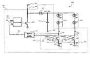
- FIG. 3illustrates an LED circuit having a set of parallel LED strings that are driven according to one embodiment of the present invention.
- FIG. 4illustrates main components of a current regulation loop used to control current variations in each of the parallel LED strings.
- FIG. 5further illustrates an exemplary implementation of the LED circuit according one embodiment of the present invention.
- An LED driver circuitfor an LED display system that includes the ability to control the current in each LED string and the voltage output.
- the present inventionalso provides improved power efficiency and scalability.
- specific detailsare set forth in order to provide a thorough understanding of the present invention. It will be understood, however, to one skilled in the art, that the present invention may be practiced without some or all of these specific details. In other instances, well known process operations have not been described in detail, as they are well known to those skilled in the art.
- FIG. 3illustrates a LED display system 300 having an LED driver 301 driving a plurality LED strings 310 1 to 310 n according to embodiments of the invention, where each LED string 310 includes a plurality of LEDs 309 .
- the LED strings 310 1 to 310 nare connected in parallel with each other, but the LEDs 309 in each LED string are series connected.
- the total number of LEDs 309 in each individual string 310may vary depending on the particular type of display system 300 that is intended. Further, the type of LEDs 309 may vary from string to string. For example, a first string 310 1 may contain one or more flash LEDs, and a second string 310 2 may contain backlighting LEDs.
- the LED driver 301includes both a voltage regulation loop 324 and current regulation loops 314 1 to 314 n , according to one embodiment of the present invention.
- the voltage Vout 308is regulated to the minimum voltage necessary to supply all of the LED strings 310 .
- the Vout 308is determined to meet the voltage requirement of the LED string 310 that requires the most voltage drop to be operational.
- the current in each LED string 310can be individually regulated by the corresponding current regulators 314 1 to 314 n .
- the LED driver 301further includes an output voltage capacitor 315 , one terminal of which is connected to a ground 330 and the other to a common node connecting the output of a voltage regulation loop 324 and anodes of the LED strings 310 1 to 310 n .
- the input to the voltage regulation loop 324includes an input voltage source VIN 326 via an inductor 325 , a reference voltage input VREF 322 , and a connection to a feedback signal 328 .
- the feedback signal 328originates from an output line 320 of a minimum voltage selector 312 .
- the output voltages 316 1 to 316 n from the cathodes of the last LEDs of the serial LED strings 310 1 - 310 nare fed into the input of the minimum voltage selector 312 .
- the number of input lines to the minimum voltages selector 312corresponds to the LED strings 310 1 - 310 n .
- the minimum voltage selector 312selects the lowest of the input voltages 316 1 - 316 n from the ends of the LED strings 310 , and then the voltage control loop 324 drives Vout 308 so that these the lowest input voltage is set approximately equal to Vref 322 . This ensures that Vout 308 is sufficient to drive all of the LED strings 310 regardless of any differing voltage requirements among the LED strings 310 .
- the current regulation loop 314 1is connected to the cathode of the last LED in the LED string 310 1 to set and maintain the current in the LED string 310 1 .
- the other serial LED strings 310 2 - 310 nhave their individual current regulation loops 314 2 - 314 n .
- the internal circuitry of the current regulation loops 314 1 - 314 nwill be described in more detail with respect to FIG. 4 .
- the operation of the voltage control loop 324 and the minimum voltage selector 312will now be described in more detail by means of an example.
- the minimum voltage selector 312selects the lowest voltage values from nodes 316 1 to 316 n and outputs the minimum voltage to the feedback input 328 .
- the control loop 332compares the minimum voltage to Vref 322 , and drives the FET 330 so that the minimum voltage 316 is equal to Vref 322 .
- the control loop 332increases or decreases the on-off duty-cycle of FET 330 so that Vout 308 adjusted as necessary in order for the minimum voltage 316 to be equal to Vref 322 .
- minimum voltage selector 312 and the voltage regulation loop 324operate so that the Vout 308 to accommodate the LED string 310 with the highest voltage drop, in order to achieve dynamic voltage regulation. But Vout 308 is not set unnecessarily high, so as to minimize power requirements. Using this technique, all the parallel serial LED strings 310 1 - 310 n will have the sufficient voltage for the individual LEDs, which are a part of a particular string.
- FIG. 4illustrates one embodiment of the current regulation loops 314 .
- the current regulation loop 314includes an operational amplifier 416 (hereinafter, referred to as “OPAMP 416 ”) having a positive input terminal 402 , a negative input terminal 404 and an output terminal 418 connected to the gate of a FET 408 .
- OPAMP 416operational amplifier 416
- the positive terminal 402receives a reference voltage VREF 1 404 , which is determined based on the desired current that is to flow through the serial LED string 310 .
- the negative terminal 404is connected to the source of the FET 408 at node 410 , which is connected to one terminal of a resistor 412 .
- the second terminal of the resistor 412is connected to a ground 414 .
- Resistor 412is preferably a highly accurate, stable resistor so that a voltage measurement at node 410 will be used to accurately determine the current through the LED string 310 .
- the drain of the FET 408is connected to the cathode of the last LED 309 of the corresponding serial LED string 310 at a node 316 , as shown.
- OPAMP 416detects the voltage drop across resistor 412 by measuring the voltage at node 410 and comparing it to VREF 1 404 .
- the OPAMP 416generates an output voltage 418 that controls the gate voltage of the FET 408 , and therefore the conductivity of FET 408 based on the difference between the voltage at node 410 and the reference voltage 404 .
- the OPAMP 416measures the voltage across the resistor 412 and drives the FET 408 so that the voltage across the resistor 412 substantially matches the reference voltage 404 .
- the conductivity of FET 416and therefore the current flow through the corresponding LED string 310 , can be adjusted higher or lower (i.e.
- the reference voltage VREF 1 404can be different for each of the serial LED strings 310 1 - 310 n so as to individually tailor the current flow through each LED string 310 .
- the current regulation loops 314individually regulate the current in each LED string 310 , according to adjustments made to the corresponding voltage reference 404 . Since the current flow controls the brightness of an LED, then adjusting the reference voltage in a particular current regulation loop also controls the brightness of the LED string 310 .
- FIG. 5further shows the LED driver 301 with the current regulation loops 314 illustrated in FIG. 4 .
- the voltage regulation loop 324provides dynamic voltage regulation by setting the output voltage Vout 308 so as to satisfy the LED string 310 with the highest voltage drop requirements.
- the current regulation loops 314also provide individual current regulation for each of the LED strings 310 , based on the corresponding reference voltages Vref 404 .
- i 1VREF ⁇ ⁇ 1 RB ⁇ ⁇ 1 ( 1 )
- VREF 1reference voltage VREF 1 404 at the positive terminal 402 of the current regulation loop 400
- RB 1resistor 412 shown in FIG. 4 . Since RB 1 is a precision resistor, it is almost of a constant value. Therefore, as can be seen from equation (1), reference voltage VREF 1 404 can be used to vary the value of the current i 1 in the first serial LED string 310 1 . The same holds true for the other serial LED strings 310 2 to 310 n , as was discussed in reference to FIG. 4 above.
- Vref 1Vref n
- Vref nVref n
- the voltage difference between the node Vout 308 and the cathode of the last LEDs 309 (node 316 ) of each of the serial LED strings 310can vary depending upon the brightness requirements for each serial LED string 310 .
- the extra or differing voltage drop between LED strings 310is accounted for by the FETs 408 in the current loops.
- the one LED string 310requires a higher voltage drop than another LED string, the extra voltage in the LED string with the lower voltage drop is dropped across the corresponding FET 408 , assuming the current loop reference voltages 404 are equal. Since different regions of the display may need different optical outputs, the flexibility in varying the output voltage VOUT 308 , if needed, adds to the design features of the LED driver 301 . Therefore, a stable output voltage VOUT 308 across the terminals of the output capacitor 315 is maintained while attaining different brightness levels for different LED strings. Meanwhile, the ability to adjust the current draw of each LED string through the current loop adds addition brightness adjusting, and power efficiency savings.
- FIG. 5is an exemplary embodiment of the present invention.
- a constant (or a static) displayis required or a varying (or a dynamic) display is required, different features of the claimed invention can be implemented, thereby resulting in more embodiments. Such embodiments will be apparent to those skilled in the art and can be learnt by the practice of the invention.
Landscapes
- Circuit Arrangement For Electric Light Sources In General (AREA)
Abstract
Description
where VREF1=
Claims (18)
Priority Applications (2)
| Application Number | Priority Date | Filing Date | Title |
|---|---|---|---|
| US11/790,221US7733034B2 (en) | 2006-09-01 | 2007-04-24 | Single inductor serial-parallel LED driver |
| US12/790,273US20110018451A1 (en) | 2006-09-01 | 2010-05-28 | Single Inductor Serial-Parallel LED Driver |
Applications Claiming Priority (2)
| Application Number | Priority Date | Filing Date | Title |
|---|---|---|---|
| US84154306P | 2006-09-01 | 2006-09-01 | |
| US11/790,221US7733034B2 (en) | 2006-09-01 | 2007-04-24 | Single inductor serial-parallel LED driver |
Related Child Applications (1)
| Application Number | Title | Priority Date | Filing Date |
|---|---|---|---|
| US12/790,273ContinuationUS20110018451A1 (en) | 2006-09-01 | 2010-05-28 | Single Inductor Serial-Parallel LED Driver |
Publications (2)
| Publication Number | Publication Date |
|---|---|
| US20080054815A1 US20080054815A1 (en) | 2008-03-06 |
| US7733034B2true US7733034B2 (en) | 2010-06-08 |
Family
ID=39150531
Family Applications (2)
| Application Number | Title | Priority Date | Filing Date |
|---|---|---|---|
| US11/790,221Expired - Fee RelatedUS7733034B2 (en) | 2006-09-01 | 2007-04-24 | Single inductor serial-parallel LED driver |
| US12/790,273AbandonedUS20110018451A1 (en) | 2006-09-01 | 2010-05-28 | Single Inductor Serial-Parallel LED Driver |
Family Applications After (1)
| Application Number | Title | Priority Date | Filing Date |
|---|---|---|---|
| US12/790,273AbandonedUS20110018451A1 (en) | 2006-09-01 | 2010-05-28 | Single Inductor Serial-Parallel LED Driver |
Country Status (1)
| Country | Link |
|---|---|
| US (2) | US7733034B2 (en) |
Cited By (27)
| Publication number | Priority date | Publication date | Assignee | Title |
|---|---|---|---|---|
| US20090195191A1 (en)* | 2008-02-05 | 2009-08-06 | Shui-Mu Lin | Perceptually linear LED brightness control |
| US20090261743A1 (en)* | 2008-04-18 | 2009-10-22 | Novatek Microelectronics Corp. | Light emitting diode driving module |
| US20090284174A1 (en)* | 2006-05-02 | 2009-11-19 | Koninklijke Philips Electronics N V | Light emitting diode circuit and arrangement and device |
| US20100219759A1 (en)* | 2009-02-27 | 2010-09-02 | Li-Chieh Chen | Short-circuit detection method and related circuit |
| US20110018451A1 (en)* | 2006-09-01 | 2011-01-27 | Broadcom Corporation | Single Inductor Serial-Parallel LED Driver |
| US20110204817A1 (en)* | 2010-02-22 | 2011-08-25 | Han Hee Seok | Light source driver, method of driving the same and devices including the same |
| US20110221346A1 (en)* | 2010-11-23 | 2011-09-15 | O2Micro, Inc. | Circuits and methods for driving light sources |
| US20120169417A1 (en)* | 2010-12-30 | 2012-07-05 | Princeton Technology Corporation | Current generator |
| US20120293215A1 (en)* | 2011-05-17 | 2012-11-22 | Ching-Tsan Lee | Driving circuit having current balancing functionality |
| WO2012177729A1 (en)* | 2011-06-20 | 2012-12-27 | Amerlux, Llc | Led driver |
| US8410711B2 (en) | 2010-12-14 | 2013-04-02 | O2Micro Inc | Circuits and methods for driving light sources |
| US8476847B2 (en) | 2011-04-22 | 2013-07-02 | Crs Electronics | Thermal foldback system |
| US8653749B2 (en) | 2011-02-21 | 2014-02-18 | Samsung Electro-Mechanics Co., Ltd. | LED driving device |
| US8669715B2 (en) | 2011-04-22 | 2014-03-11 | Crs Electronics | LED driver having constant input current |
| US8669711B2 (en) | 2011-04-22 | 2014-03-11 | Crs Electronics | Dynamic-headroom LED power supply |
| US20140070705A1 (en)* | 2012-09-13 | 2014-03-13 | Raydium Semiconductor Corporation | Led driving apparatus and operating method thereof |
| US20140159597A1 (en)* | 2012-12-07 | 2014-06-12 | Princeton Technology Corporation | Lighting system and control method thereof |
| US20140333216A1 (en)* | 2013-05-10 | 2014-11-13 | Marvell World Trade Ltd. | Multi-string dimmable led driver |
| US8907591B2 (en) | 2010-01-04 | 2014-12-09 | Cooledge Lighting Inc. | Method and system for driving light emitting elements |
| US20150002034A1 (en)* | 2011-03-03 | 2015-01-01 | Cree, Inc. | Semiconductor Light Emitting Devices Having Selectable and/or Adjustable Color Points and Related Methods |
| US8988004B2 (en) | 2013-01-18 | 2015-03-24 | Semiconductor Components Industries, Llc | Method of forming a current controller for an LED and structure therefor |
| US8988005B2 (en) | 2011-02-17 | 2015-03-24 | Cooledge Lighting Inc. | Illumination control through selective activation and de-activation of lighting elements |
| US9030121B2 (en) | 2010-11-23 | 2015-05-12 | O2Micro, Inc. | Circuits and methods for driving light sources |
| US9769888B2 (en)* | 2015-06-09 | 2017-09-19 | Silergy Semiconductor Technology (Hangzhou) Ltd | Driving circuit and driving method for a plurality of LED strings |
| US10547306B1 (en)* | 2016-10-18 | 2020-01-28 | Synapse Wireless, Inc. | Circuit to reduce power consumption |
| US20200127564A1 (en)* | 2018-10-17 | 2020-04-23 | Dialog Semiconductor (Uk) Limited | Current Regulator |
| US10797698B1 (en)* | 2019-11-29 | 2020-10-06 | Waymo Llc | Systems and methods for selecting light emitters for emitting light |
Families Citing this family (101)
| Publication number | Priority date | Publication date | Assignee | Title |
|---|---|---|---|---|
| US8723438B2 (en)* | 2007-03-12 | 2014-05-13 | Cirrus Logic, Inc. | Switch power converter control with spread spectrum based electromagnetic interference reduction |
| US8076920B1 (en) | 2007-03-12 | 2011-12-13 | Cirrus Logic, Inc. | Switching power converter and control system |
| US7667408B2 (en) | 2007-03-12 | 2010-02-23 | Cirrus Logic, Inc. | Lighting system with lighting dimmer output mapping |
| US8174204B2 (en)* | 2007-03-12 | 2012-05-08 | Cirrus Logic, Inc. | Lighting system with power factor correction control data determined from a phase modulated signal |
| US8018171B1 (en) | 2007-03-12 | 2011-09-13 | Cirrus Logic, Inc. | Multi-function duty cycle modifier |
| US7554473B2 (en) | 2007-05-02 | 2009-06-30 | Cirrus Logic, Inc. | Control system using a nonlinear delta-sigma modulator with nonlinear process modeling |
| US8102127B2 (en) | 2007-06-24 | 2012-01-24 | Cirrus Logic, Inc. | Hybrid gas discharge lamp-LED lighting system |
| EP2181566A2 (en)* | 2007-08-24 | 2010-05-05 | Cirrus Logic, Inc. | Multi-led control |
| US7893626B2 (en)* | 2007-09-07 | 2011-02-22 | Richtek Technology Corporation | Multi-color backlight control circuit and multi-color backlight control method |
| DE102007045777A1 (en)* | 2007-09-25 | 2009-04-09 | Continental Automotive Gmbh | Scalable LED control with minimized power loss |
| US8576589B2 (en) | 2008-01-30 | 2013-11-05 | Cirrus Logic, Inc. | Switch state controller with a sense current generated operating voltage |
| US8008898B2 (en)* | 2008-01-30 | 2011-08-30 | Cirrus Logic, Inc. | Switching regulator with boosted auxiliary winding supply |
| US8022683B2 (en) | 2008-01-30 | 2011-09-20 | Cirrus Logic, Inc. | Powering a power supply integrated circuit with sense current |
| TWI390482B (en)* | 2008-02-19 | 2013-03-21 | Himax Analogic Inc | The circuit and method for driving strings of light emitting diode |
| US7825610B2 (en)* | 2008-03-12 | 2010-11-02 | Freescale Semiconductor, Inc. | LED driver with dynamic power management |
| US8115414B2 (en)* | 2008-03-12 | 2012-02-14 | Freescale Semiconductor, Inc. | LED driver with segmented dynamic headroom control |
| US8106604B2 (en)* | 2008-03-12 | 2012-01-31 | Freescale Semiconductor, Inc. | LED driver with dynamic power management |
| US10743384B2 (en)* | 2013-11-18 | 2020-08-11 | Ideal Industries Lighting Llc | Systems and methods for a current sharing driver for light emitting diodes |
| USRE49637E1 (en) | 2008-04-04 | 2023-08-29 | Ideal Industries Lighting Llc | Systems and methods for high output, high color quality light |
| US9593837B2 (en) | 2008-04-04 | 2017-03-14 | Cree, Inc. | Systems and methods for high output, high color quality light |
| US8035314B2 (en)* | 2008-06-23 | 2011-10-11 | Freescale Semiconductor, Inc. | Method and device for LED channel managment in LED driver |
| US8212491B2 (en) | 2008-07-25 | 2012-07-03 | Cirrus Logic, Inc. | Switching power converter control with triac-based leading edge dimmer compatibility |
| US8344707B2 (en) | 2008-07-25 | 2013-01-01 | Cirrus Logic, Inc. | Current sensing in a switching power converter |
| US8847719B2 (en)* | 2008-07-25 | 2014-09-30 | Cirrus Logic, Inc. | Transformer with split primary winding |
| US8279144B2 (en)* | 2008-07-31 | 2012-10-02 | Freescale Semiconductor, Inc. | LED driver with frame-based dynamic power management |
| TWI508622B (en)* | 2008-08-28 | 2015-11-11 | Koninkl Philips Nv | Method and circuit for controlling an led load |
| US8487546B2 (en) | 2008-08-29 | 2013-07-16 | Cirrus Logic, Inc. | LED lighting system with accurate current control |
| US8179110B2 (en) | 2008-09-30 | 2012-05-15 | Cirrus Logic Inc. | Adjustable constant current source with continuous conduction mode (“CCM”) and discontinuous conduction mode (“DCM”) operation |
| US8222872B1 (en) | 2008-09-30 | 2012-07-17 | Cirrus Logic, Inc. | Switching power converter with selectable mode auxiliary power supply |
| US8373643B2 (en)* | 2008-10-03 | 2013-02-12 | Freescale Semiconductor, Inc. | Frequency synthesis and synchronization for LED drivers |
| JP2010135136A (en)* | 2008-12-03 | 2010-06-17 | Panasonic Electric Works Co Ltd | Led lighting device |
| US8004207B2 (en)* | 2008-12-03 | 2011-08-23 | Freescale Semiconductor, Inc. | LED driver with precharge and track/hold |
| US8288954B2 (en) | 2008-12-07 | 2012-10-16 | Cirrus Logic, Inc. | Primary-side based control of secondary-side current for a transformer |
| US8362707B2 (en) | 2008-12-12 | 2013-01-29 | Cirrus Logic, Inc. | Light emitting diode based lighting system with time division ambient light feedback response |
| US8299722B2 (en) | 2008-12-12 | 2012-10-30 | Cirrus Logic, Inc. | Time division light output sensing and brightness adjustment for different spectra of light emitting diodes |
| US8035315B2 (en)* | 2008-12-22 | 2011-10-11 | Freescale Semiconductor, Inc. | LED driver with feedback calibration |
| US7994863B2 (en) | 2008-12-31 | 2011-08-09 | Cirrus Logic, Inc. | Electronic system having common mode voltage range enhancement |
| US8049439B2 (en)* | 2009-01-30 | 2011-11-01 | Freescale Semiconductor, Inc. | LED driver with dynamic headroom control |
| US8179051B2 (en)* | 2009-02-09 | 2012-05-15 | Freescale Semiconductor, Inc. | Serial configuration for dynamic power control in LED displays |
| US8493003B2 (en)* | 2009-02-09 | 2013-07-23 | Freescale Semiconductor, Inc. | Serial cascade of minimium tail voltages of subsets of LED strings for dynamic power control in LED displays |
| US20100244711A1 (en)* | 2009-03-30 | 2010-09-30 | Richard Landry Gray | Self-Calibrating White Light Emitting Diode Module |
| US8040079B2 (en)* | 2009-04-15 | 2011-10-18 | Freescale Semiconductor, Inc. | Peak detection with digital conversion |
| DE102009018098A1 (en) | 2009-04-20 | 2010-10-21 | Austriamicrosystems Ag | Charging circuit for a charge storage and method for loading such |
| US8482223B2 (en) | 2009-04-30 | 2013-07-09 | Cirrus Logic, Inc. | Calibration of lamps |
| US20100295472A1 (en)* | 2009-05-06 | 2010-11-25 | Polar Semiconductor, Inc. | Power supply for floating loads |
| US8564155B2 (en)* | 2009-05-06 | 2013-10-22 | Polar Semiconductor, Inc. | Multiple output power supply |
| US8212493B2 (en)* | 2009-06-30 | 2012-07-03 | Cirrus Logic, Inc. | Low energy transfer mode for auxiliary power supply operation in a cascaded switching power converter |
| US8248145B2 (en) | 2009-06-30 | 2012-08-21 | Cirrus Logic, Inc. | Cascode configured switching using at least one low breakdown voltage internal, integrated circuit switch to control at least one high breakdown voltage external switch |
| US8963535B1 (en) | 2009-06-30 | 2015-02-24 | Cirrus Logic, Inc. | Switch controlled current sensing using a hall effect sensor |
| US8198874B2 (en) | 2009-06-30 | 2012-06-12 | Cirrus Logic, Inc. | Switching power converter with current sensing transformer auxiliary power supply |
| US8305007B2 (en)* | 2009-07-17 | 2012-11-06 | Freescale Semiconductor, Inc. | Analog-to-digital converter with non-uniform accuracy |
| US8228098B2 (en)* | 2009-08-07 | 2012-07-24 | Freescale Semiconductor, Inc. | Pulse width modulation frequency conversion |
| US7843242B1 (en) | 2009-08-07 | 2010-11-30 | Freescale Semiconductor, Inc. | Phase-shifted pulse width modulation signal generation |
| TW201107916A (en)* | 2009-08-24 | 2011-03-01 | Novatek Microelectronics Corp | Light emitting device capable of dynamically regulating output voltage and related control method |
| US9155174B2 (en) | 2009-09-30 | 2015-10-06 | Cirrus Logic, Inc. | Phase control dimming compatible lighting systems |
| US8294375B2 (en)* | 2009-10-08 | 2012-10-23 | Intersil Americas Inc | Adaptive PWM controller for multi-phase LED driver |
| US9178415B1 (en) | 2009-10-15 | 2015-11-03 | Cirrus Logic, Inc. | Inductor over-current protection using a volt-second value representing an input voltage to a switching power converter |
| US8654483B2 (en) | 2009-11-09 | 2014-02-18 | Cirrus Logic, Inc. | Power system having voltage-based monitoring for over current protection |
| US8237700B2 (en)* | 2009-11-25 | 2012-08-07 | Freescale Semiconductor, Inc. | Synchronized phase-shifted pulse width modulation signal generation |
| US8169245B2 (en)* | 2010-02-10 | 2012-05-01 | Freescale Semiconductor, Inc. | Duty transition control in pulse width modulation signaling |
| US9490792B2 (en)* | 2010-02-10 | 2016-11-08 | Freescale Semiconductor, Inc. | Pulse width modulation with effective high duty resolution |
| DE102010015088A1 (en)* | 2010-03-19 | 2011-09-22 | Dilitronics Gmbh | Power dissipation reduction circuit arrangement for linear current driver of LED utilized in e.g. optical system, has driver stage whose output is connected with LEDs, where power supply voltage of each LED is adjusted by varying variable |
| US8872439B2 (en)* | 2010-04-30 | 2014-10-28 | Texas Instruments Incorporated | System and methods for providing equal currents to current driven loads |
| CN102264173B (en)* | 2010-05-31 | 2013-11-06 | 英飞特电子(杭州)股份有限公司 | LED (light emitting diode) constant current driving circuit and output-voltage-adjustable circuit |
| CN101872596A (en)* | 2010-06-25 | 2010-10-27 | 福建捷联电子有限公司 | Liquid crystal television LED-string voltage control adjusting circuit |
| US8729811B2 (en) | 2010-07-30 | 2014-05-20 | Cirrus Logic, Inc. | Dimming multiple lighting devices by alternating energy transfer from a magnetic storage element |
| US8536799B1 (en) | 2010-07-30 | 2013-09-17 | Cirrus Logic, Inc. | Dimmer detection |
| US8569972B2 (en) | 2010-08-17 | 2013-10-29 | Cirrus Logic, Inc. | Dimmer output emulation |
| US9173261B2 (en) | 2010-07-30 | 2015-10-27 | Wesley L. Mokry | Secondary-side alternating energy transfer control with inverted reference and LED-derived power supply |
| DE102010033640B4 (en)* | 2010-08-06 | 2018-07-12 | Austriamicrosystems Ag | Circuit arrangement and method for operating light-emitting diodes and illumination arrangement |
| US9433047B2 (en) | 2010-08-23 | 2016-08-30 | Active-Semi, Inc. | Single inductor multiple LED string driver |
| CN101917809B (en)* | 2010-08-24 | 2013-11-13 | 成都芯源系统有限公司 | Driver for driving a plurality of light emitting elements, driving method, and display device |
| US8390215B2 (en)* | 2010-10-07 | 2013-03-05 | Himax Analogic, Inc. | Light emitting diode circuit, light emitting diode driving circuit, voltage selection circuit, and method for driving thereof |
| US8674620B2 (en)* | 2010-11-30 | 2014-03-18 | Infineon Technologies Ag | Multi channel LED driver |
| TWI426823B (en) | 2010-12-24 | 2014-02-11 | Au Optronics Corp | Terminal voltage control circuit for light emitting diode (led) string and led illumination device |
| US8599915B2 (en) | 2011-02-11 | 2013-12-03 | Freescale Semiconductor, Inc. | Phase-shifted pulse width modulation signal generation device and method therefor |
| US8823289B2 (en) | 2011-03-24 | 2014-09-02 | Cirrus Logic, Inc. | Color coordination of electronic light sources with dimming and temperature responsiveness |
| US8912734B2 (en) | 2011-03-24 | 2014-12-16 | Cirrus Logic, Inc. | Color mixing of electronic light sources with correlation between phase-cut dimmer angle and predetermined black body radiation function |
| GB2492833A (en)* | 2011-07-14 | 2013-01-16 | Softkinetic Sensors Nv | LED boost converter driver circuit for Time Of Flight light sources |
| US20130026933A1 (en)* | 2011-07-25 | 2013-01-31 | Shenzhen China Star Optoelectronics Technology Co., Ltd. | Led backlight drive circuit |
| US20130044272A1 (en)* | 2011-08-18 | 2013-02-21 | Xinming Gao | LED Backlight Driving Method, LED Backlight Driving Circuit and Liquid Crystal Display Device |
| DE102011112455A1 (en)* | 2011-09-03 | 2013-03-07 | Vision Components Gesellschaft für Bildverarbeitungsysteme mbH | Method for supplying power to LED in e.g. camera for image processing system, involves controlling output voltage of switching regulator by measured voltage drop as feedback signal during measuring period |
| KR101940780B1 (en)* | 2011-09-16 | 2019-01-22 | 서울반도체 주식회사 | Illumination Apparatus Comprising Semiconductor Light Emitting Diodes |
| US8786211B2 (en) | 2011-12-15 | 2014-07-22 | Cree, Inc. | Current control for SIMO converters |
| US9099921B2 (en)* | 2011-12-15 | 2015-08-04 | Cree, Inc. | Integrating circuitry for measuring current in a SIMO converter |
| US9106133B2 (en) | 2011-12-15 | 2015-08-11 | Cree, Inc. | Arrangements of current conduction for SIMO converters |
| US8841860B2 (en) | 2011-12-15 | 2014-09-23 | Cree, Inc. | SIMO converters that generate a light output |
| EP2621247B1 (en)* | 2012-01-25 | 2015-09-30 | Dialog Semiconductor GmbH | Dimming method and system for LED lamp assemblies |
| US9204503B1 (en) | 2012-07-03 | 2015-12-01 | Philips International, B.V. | Systems and methods for dimming multiple lighting devices by alternating transfer from a magnetic storage element |
| US9024532B2 (en)* | 2012-12-14 | 2015-05-05 | Shenzhen China Star Optoelectronics Technology Co., Ltd. | Direct type LED backlight and liquid crystal display thereof |
| JP6086755B2 (en)* | 2013-02-26 | 2017-03-01 | 国立大学法人九州大学 | Optical analysis method and optical analysis apparatus using microchip, and processing apparatus for optical analysis |
| JP6157639B2 (en)* | 2013-09-19 | 2017-07-05 | フィリップス ライティング ホールディング ビー ヴィ | Light emitting diode driver with differential voltage supply |
| US9504103B2 (en) | 2013-10-21 | 2016-11-22 | Osram Sylvania Inc. | Driving a multi-color luminaire |
| WO2016037780A1 (en)* | 2014-09-12 | 2016-03-17 | Philips Lighting Holding B.V. | Led dimmer circuit and method |
| TWI596988B (en)* | 2015-11-12 | 2017-08-21 | 台灣快捷國際股份有限公司 | Led driver |
| CN106253670A (en)* | 2016-08-23 | 2016-12-21 | 深圳市华星光电技术有限公司 | Booster circuit and back light |
| CN106354075B (en)* | 2016-11-25 | 2020-01-21 | 北京意同创科技有限公司 | Remote controller control circuit with backlight screen |
| TWM579865U (en)* | 2018-11-30 | 2019-06-21 | 宏碁股份有限公司 | Light-emitting diode driving circuit |
| JP7265419B2 (en)* | 2019-06-05 | 2023-04-26 | ローム株式会社 | Light-emitting element driving device |
| EP4021149A1 (en) | 2020-12-22 | 2022-06-29 | Textron Systems Corporation | Light appartus with parallel-arranged leds and per-led drivers |
| CN114743494B (en)* | 2022-04-27 | 2024-08-06 | 绵阳惠科光电科技有限公司 | Control circuit, driving device and display |
Citations (8)
| Publication number | Priority date | Publication date | Assignee | Title |
|---|---|---|---|---|
| US20010043113A1 (en)* | 2000-05-12 | 2001-11-22 | Taichi Hoshino | LED drive circuit |
| US6498440B2 (en)* | 2000-03-27 | 2002-12-24 | Gentex Corporation | Lamp assembly incorporating optical feedback |
| US6556067B2 (en)* | 2000-06-13 | 2003-04-29 | Linfinity Microelectronics | Charge pump regulator with load current control |
| US6636104B2 (en)* | 2000-06-13 | 2003-10-21 | Microsemi Corporation | Multiple output charge pump |
| US20040252096A1 (en)* | 2003-05-21 | 2004-12-16 | Der-Jiunn Wang | Dual panel display backlight power controller chip for handheld apparatus |
| US6836157B2 (en)* | 2003-05-09 | 2004-12-28 | Semtech Corporation | Method and apparatus for driving LEDs |
| US6847169B2 (en)* | 2002-10-08 | 2005-01-25 | Koito Manufacturing Co., Ltd. | Lighting circuit |
| US6864641B2 (en)* | 2003-02-20 | 2005-03-08 | Visteon Global Technologies, Inc. | Method and apparatus for controlling light emitting diodes |
Family Cites Families (2)
| Publication number | Priority date | Publication date | Assignee | Title |
|---|---|---|---|---|
| JP4001856B2 (en)* | 2003-10-30 | 2007-10-31 | ローム株式会社 | LIGHT EMITTING ELEMENT DRIVE DEVICE, DISPLAY MODULE HAVING LIGHT EMITTING ELEMENT DRIVE DEVICE, AND ELECTRONIC DEVICE HAVING DISPLAY MODULE |
| US7733034B2 (en)* | 2006-09-01 | 2010-06-08 | Broadcom Corporation | Single inductor serial-parallel LED driver |
- 2007
- 2007-04-24USUS11/790,221patent/US7733034B2/ennot_activeExpired - Fee Related
- 2010
- 2010-05-28USUS12/790,273patent/US20110018451A1/ennot_activeAbandoned
Patent Citations (10)
| Publication number | Priority date | Publication date | Assignee | Title |
|---|---|---|---|---|
| US6498440B2 (en)* | 2000-03-27 | 2002-12-24 | Gentex Corporation | Lamp assembly incorporating optical feedback |
| US20010043113A1 (en)* | 2000-05-12 | 2001-11-22 | Taichi Hoshino | LED drive circuit |
| US6556067B2 (en)* | 2000-06-13 | 2003-04-29 | Linfinity Microelectronics | Charge pump regulator with load current control |
| US6636104B2 (en)* | 2000-06-13 | 2003-10-21 | Microsemi Corporation | Multiple output charge pump |
| US6897709B2 (en)* | 2000-06-13 | 2005-05-24 | Microsemi Corporation | Charge pump regulator with load current control |
| US6847169B2 (en)* | 2002-10-08 | 2005-01-25 | Koito Manufacturing Co., Ltd. | Lighting circuit |
| US6864641B2 (en)* | 2003-02-20 | 2005-03-08 | Visteon Global Technologies, Inc. | Method and apparatus for controlling light emitting diodes |
| US6836157B2 (en)* | 2003-05-09 | 2004-12-28 | Semtech Corporation | Method and apparatus for driving LEDs |
| US7459959B2 (en)* | 2003-05-09 | 2008-12-02 | Semtech Corporation | Method and apparatus for driving LED's |
| US20040252096A1 (en)* | 2003-05-21 | 2004-12-16 | Der-Jiunn Wang | Dual panel display backlight power controller chip for handheld apparatus |
Cited By (41)
| Publication number | Priority date | Publication date | Assignee | Title |
|---|---|---|---|---|
| US20090284174A1 (en)* | 2006-05-02 | 2009-11-19 | Koninklijke Philips Electronics N V | Light emitting diode circuit and arrangement and device |
| US8076872B2 (en)* | 2006-05-02 | 2011-12-13 | Koninklijke Philips Electronics N.V. | Light emitting diode circuit and arrangement and device |
| US20110018451A1 (en)* | 2006-09-01 | 2011-01-27 | Broadcom Corporation | Single Inductor Serial-Parallel LED Driver |
| US20090195191A1 (en)* | 2008-02-05 | 2009-08-06 | Shui-Mu Lin | Perceptually linear LED brightness control |
| US8198830B2 (en)* | 2008-02-05 | 2012-06-12 | Richtek Technology Corp. | Perceptually linear LED brightness control |
| US8018170B2 (en)* | 2008-04-18 | 2011-09-13 | Novatek Microelectronics Corp. | Light emitting diode driving module |
| US20090261743A1 (en)* | 2008-04-18 | 2009-10-22 | Novatek Microelectronics Corp. | Light emitting diode driving module |
| US20100219759A1 (en)* | 2009-02-27 | 2010-09-02 | Li-Chieh Chen | Short-circuit detection method and related circuit |
| US8907591B2 (en) | 2010-01-04 | 2014-12-09 | Cooledge Lighting Inc. | Method and system for driving light emitting elements |
| US8581830B2 (en)* | 2010-02-22 | 2013-11-12 | Samsung Electronics Co., Ltd. | Light source driver, method of driving the same and devices including the same |
| US20110204817A1 (en)* | 2010-02-22 | 2011-08-25 | Han Hee Seok | Light source driver, method of driving the same and devices including the same |
| US20110221346A1 (en)* | 2010-11-23 | 2011-09-15 | O2Micro, Inc. | Circuits and methods for driving light sources |
| US9030121B2 (en) | 2010-11-23 | 2015-05-12 | O2Micro, Inc. | Circuits and methods for driving light sources |
| US8564219B2 (en)* | 2010-11-23 | 2013-10-22 | O2Micro, Inc. | Circuits and methods for driving light sources |
| US8410711B2 (en) | 2010-12-14 | 2013-04-02 | O2Micro Inc | Circuits and methods for driving light sources |
| US20120169417A1 (en)* | 2010-12-30 | 2012-07-05 | Princeton Technology Corporation | Current generator |
| US8648548B2 (en)* | 2010-12-30 | 2014-02-11 | Princeton Technology Corporation | Current generator |
| US8988005B2 (en) | 2011-02-17 | 2015-03-24 | Cooledge Lighting Inc. | Illumination control through selective activation and de-activation of lighting elements |
| US8653749B2 (en) | 2011-02-21 | 2014-02-18 | Samsung Electro-Mechanics Co., Ltd. | LED driving device |
| US9006986B2 (en)* | 2011-03-03 | 2015-04-14 | Cree, Inc. | Semiconductor light emitting devices having selectable and/or adjustable color points and related methods |
| US20150002034A1 (en)* | 2011-03-03 | 2015-01-01 | Cree, Inc. | Semiconductor Light Emitting Devices Having Selectable and/or Adjustable Color Points and Related Methods |
| US8669711B2 (en) | 2011-04-22 | 2014-03-11 | Crs Electronics | Dynamic-headroom LED power supply |
| US8669715B2 (en) | 2011-04-22 | 2014-03-11 | Crs Electronics | LED driver having constant input current |
| US8476847B2 (en) | 2011-04-22 | 2013-07-02 | Crs Electronics | Thermal foldback system |
| US20120293215A1 (en)* | 2011-05-17 | 2012-11-22 | Ching-Tsan Lee | Driving circuit having current balancing functionality |
| US8471605B2 (en)* | 2011-05-17 | 2013-06-25 | Leadtrend Technology Corp. | Driving circuit having current balancing functionality |
| WO2012177729A1 (en)* | 2011-06-20 | 2012-12-27 | Amerlux, Llc | Led driver |
| US9338841B2 (en) | 2011-06-20 | 2016-05-10 | Amerlux Llc | LED driver |
| US20140070705A1 (en)* | 2012-09-13 | 2014-03-13 | Raydium Semiconductor Corporation | Led driving apparatus and operating method thereof |
| US20140159597A1 (en)* | 2012-12-07 | 2014-06-12 | Princeton Technology Corporation | Lighting system and control method thereof |
| US8957606B2 (en)* | 2012-12-07 | 2015-02-17 | Princeton Technology Corporation | Lighting system and control method thereof |
| US8988004B2 (en) | 2013-01-18 | 2015-03-24 | Semiconductor Components Industries, Llc | Method of forming a current controller for an LED and structure therefor |
| US20140333216A1 (en)* | 2013-05-10 | 2014-11-13 | Marvell World Trade Ltd. | Multi-string dimmable led driver |
| US9320097B2 (en)* | 2013-05-10 | 2016-04-19 | Marvell World Trade Ltd. | Multi-string dimmable LED driver |
| US9769888B2 (en)* | 2015-06-09 | 2017-09-19 | Silergy Semiconductor Technology (Hangzhou) Ltd | Driving circuit and driving method for a plurality of LED strings |
| US10547306B1 (en)* | 2016-10-18 | 2020-01-28 | Synapse Wireless, Inc. | Circuit to reduce power consumption |
| US20200127564A1 (en)* | 2018-10-17 | 2020-04-23 | Dialog Semiconductor (Uk) Limited | Current Regulator |
| US11043897B2 (en)* | 2018-10-17 | 2021-06-22 | Dialog Semiconductor (Uk) Limited | Current regulator |
| US10797698B1 (en)* | 2019-11-29 | 2020-10-06 | Waymo Llc | Systems and methods for selecting light emitters for emitting light |
| US11677398B2 (en) | 2019-11-29 | 2023-06-13 | Waymo Llc | Systems and methods for selecting light emitters for emitting light |
| US12206406B2 (en) | 2019-11-29 | 2025-01-21 | Waymo Llc | Systems and methods for selecting light emitters for emitting light |
Also Published As
| Publication number | Publication date |
|---|---|
| US20110018451A1 (en) | 2011-01-27 |
| US20080054815A1 (en) | 2008-03-06 |
Similar Documents
| Publication | Publication Date | Title |
|---|---|---|
| US7733034B2 (en) | Single inductor serial-parallel LED driver | |
| US7459959B2 (en) | Method and apparatus for driving LED's | |
| KR101480201B1 (en) | Driving circuit for light emitting element, and electronic device | |
| KR101126804B1 (en) | Led array control circuit with voltage adjustment function and driver circuit and method for the same | |
| US7683553B2 (en) | LED current control circuits and methods | |
| KR101159931B1 (en) | Power supply system and method for the operation of an electrical load | |
| US7307614B2 (en) | Light emitting diode driver circuit | |
| US8148919B2 (en) | Circuits and methods for driving light sources | |
| US7679351B2 (en) | Power supply apparatus | |
| US7948455B2 (en) | Apparatus and method for regulating white LEDs | |
| US8941325B2 (en) | Light emitting device array driver circuit and current splitter circuit and method of splitting current therefor | |
| JP5004700B2 (en) | Light emitting element driving device | |
| US20060186827A1 (en) | Supply device of circuit branches with LED diodes | |
| US20090085538A1 (en) | Power Supply Device, Electronic Device, and A/D Converter Used for Them | |
| US20070085786A1 (en) | System and method for driving keypad backlight with balance-dimming capability | |
| US20070217094A1 (en) | Switching regulator | |
| KR101154837B1 (en) | Driver IC for electrical road and driving method thereof | |
| US9942956B1 (en) | Boost converter design with 100%-pass mode for WLED backlight and camera flash applications | |
| JP2008035297A (en) | POWER CIRCUIT DEVICE AND ELECTRONIC DEVICE HAVING THE POWER CIRCUIT DEVICE |
Legal Events
| Date | Code | Title | Description |
|---|---|---|---|
| AS | Assignment | Owner name:BROADCOM CORPORATION, CALIFORNIA Free format text:ASSIGNMENT OF ASSIGNORS INTEREST;ASSIGNORS:KOTIKALAPOODI, SRIDHAR V.;ZENG, JAMES;PANDYA, MANISHA P.;AND OTHERS;REEL/FRAME:021919/0672 Effective date:20061130 Owner name:BROADCOM CORPORATION,CALIFORNIA Free format text:ASSIGNMENT OF ASSIGNORS INTEREST;ASSIGNORS:KOTIKALAPOODI, SRIDHAR V.;ZENG, JAMES;PANDYA, MANISHA P.;AND OTHERS;REEL/FRAME:021919/0672 Effective date:20061130 | |
| AS | Assignment | Owner name:BROADCOM CORPORATION, CALIFORNIA Free format text:ASSIGNMENT OF ASSIGNORS INTEREST;ASSIGNOR:SZABO, TIVADAR;REEL/FRAME:023122/0445 Effective date:20050915 Owner name:BROADCOM CORPORATION,CALIFORNIA Free format text:ASSIGNMENT OF ASSIGNORS INTEREST;ASSIGNOR:SZABO, TIVADAR;REEL/FRAME:023122/0445 Effective date:20050915 | |
| STCF | Information on status: patent grant | Free format text:PATENTED CASE | |
| FPAY | Fee payment | Year of fee payment:4 | |
| AS | Assignment | Owner name:BANK OF AMERICA, N.A., AS COLLATERAL AGENT, NORTH CAROLINA Free format text:PATENT SECURITY AGREEMENT;ASSIGNOR:BROADCOM CORPORATION;REEL/FRAME:037806/0001 Effective date:20160201 Owner name:BANK OF AMERICA, N.A., AS COLLATERAL AGENT, NORTH Free format text:PATENT SECURITY AGREEMENT;ASSIGNOR:BROADCOM CORPORATION;REEL/FRAME:037806/0001 Effective date:20160201 | |
| AS | Assignment | Owner name:AVAGO TECHNOLOGIES GENERAL IP (SINGAPORE) PTE. LTD., SINGAPORE Free format text:ASSIGNMENT OF ASSIGNORS INTEREST;ASSIGNOR:BROADCOM CORPORATION;REEL/FRAME:041706/0001 Effective date:20170120 Owner name:AVAGO TECHNOLOGIES GENERAL IP (SINGAPORE) PTE. LTD Free format text:ASSIGNMENT OF ASSIGNORS INTEREST;ASSIGNOR:BROADCOM CORPORATION;REEL/FRAME:041706/0001 Effective date:20170120 | |
| AS | Assignment | Owner name:BROADCOM CORPORATION, CALIFORNIA Free format text:TERMINATION AND RELEASE OF SECURITY INTEREST IN PATENTS;ASSIGNOR:BANK OF AMERICA, N.A., AS COLLATERAL AGENT;REEL/FRAME:041712/0001 Effective date:20170119 | |
| MAFP | Maintenance fee payment | Free format text:PAYMENT OF MAINTENANCE FEE, 8TH YEAR, LARGE ENTITY (ORIGINAL EVENT CODE: M1552) Year of fee payment:8 | |
| AS | Assignment | Owner name:AVAGO TECHNOLOGIES INTERNATIONAL SALES PTE. LIMITE Free format text:MERGER;ASSIGNOR:AVAGO TECHNOLOGIES GENERAL IP (SINGAPORE) PTE. LTD.;REEL/FRAME:047196/0687 Effective date:20180509 | |
| AS | Assignment | Owner name:AVAGO TECHNOLOGIES INTERNATIONAL SALES PTE. LIMITE Free format text:CORRECTIVE ASSIGNMENT TO CORRECT THE EFFECTIVE DATE OF MERGER TO 9/5/2018 PREVIOUSLY RECORDED AT REEL: 047196 FRAME: 0687. ASSIGNOR(S) HEREBY CONFIRMS THE MERGER;ASSIGNOR:AVAGO TECHNOLOGIES GENERAL IP (SINGAPORE) PTE. LTD.;REEL/FRAME:047630/0344 Effective date:20180905 | |
| AS | Assignment | Owner name:AVAGO TECHNOLOGIES INTERNATIONAL SALES PTE. LIMITE Free format text:CORRECTIVE ASSIGNMENT TO CORRECT THE PROPERTY NUMBERS PREVIOUSLY RECORDED AT REEL: 47630 FRAME: 344. ASSIGNOR(S) HEREBY CONFIRMS THE ASSIGNMENT;ASSIGNOR:AVAGO TECHNOLOGIES GENERAL IP (SINGAPORE) PTE. LTD.;REEL/FRAME:048883/0267 Effective date:20180905 | |
| FEPP | Fee payment procedure | Free format text:MAINTENANCE FEE REMINDER MAILED (ORIGINAL EVENT CODE: REM.); ENTITY STATUS OF PATENT OWNER: LARGE ENTITY | |
| LAPS | Lapse for failure to pay maintenance fees | Free format text:PATENT EXPIRED FOR FAILURE TO PAY MAINTENANCE FEES (ORIGINAL EVENT CODE: EXP.); ENTITY STATUS OF PATENT OWNER: LARGE ENTITY | |
| STCH | Information on status: patent discontinuation | Free format text:PATENT EXPIRED DUE TO NONPAYMENT OF MAINTENANCE FEES UNDER 37 CFR 1.362 | |
| FP | Lapsed due to failure to pay maintenance fee | Effective date:20220608 |